Embed Size (px)
Citation preview
■ How the Pump Works, Advantages of the HII Pumps, How to Select Air Driven Pumps .........................................................2■ Typical Applications .............................................................................3■ Model Selection Table ..........................................................................4■ Type of Materials in Contact with Fluid, Liquid Compatibility and Operating Temperature Limits .....................................................5■ Dimensional Data, Port Details .......................................................6, 7
CONTENTS
LP500D
AIR DRIVEN AIR DRIVEN LIQUID PUMPSLIQUID PUMPS
HIIHy
drau
lics
Inte
rnat
iona
l, In
c.
■ Performance Curves ............................................................8, 9, 10, 11■ Compressibility of Water ...................................................................11■ Standard Modifications .....................................................................12 ■ HII Power Units .................................................................................13■ Other HII Quality Products .................................................................14■ Hydraulics International, Inc. - Overview .........................................15
HYDRAULICS INTERNATIONAL, INC. (818) 407-3400
ADVANTAGES OF THE HII PUMPS
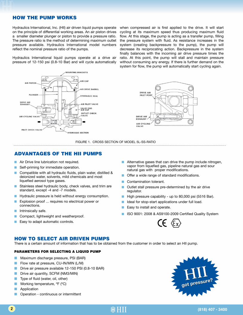
Hydraulics International, Inc. (HII) air driven liquid pumps operate on the principle of differential working areas. An air piston drives a smaller diameter plunger or piston to provide a pressure ratio. The pressure ratio is the method of determining maximum outlet pressure available. Hydraulics International model numbers reflect the nominal pressure ratio of the pumps.
Hydraulics International liquid pumps operate at a drive air pressure of 12-150 psi (0.8-10 Bar) and will cycle automatically
when compressed air is first applied to the drive. It will start cycling at its maximum speed thus producing maximum fluid flow. At this stage, the pump is acting as a transfer pump, filling the pressure system with fluid. As resistance increases in the system (creating backpressure to the pump), the pump will decrease its reciprocating action. Backpressure in the system finally balances with the incoming air drive pressure times the ratio. At this point, the pump will stall and maintain pressure without consuming any energy. If there is further demand on the system for flow, the pump will automatically start cycling again.
■ Air Drive line lubrication not required.■ Self-priming for immediate operation.■ Compatible with all hydraulic fluids, plain water, distilled &
deionized water, solvents, mild chemicals and most liquefied aerosol type gases.
■ Stainless steel hydraulic body, check valves, and trim are standard, except -4 and -7 models.
■ Alternative gases that can drive the pump include nitrogen, vapor from liquefied gas, pipeline natural gas and sour natural gas with proper modifications.
■ Offer a wide range of standard modifications.
■ Hydraulic pressure is held without energy consumption.■ Explosion proof ... requires no electrical power or
connections.■ Intrinsically safe.■ Compact, lightweight and weatherproof.■ Easy to adapt automatic controls.
■ Contamination tolerant.■ Outlet stall pressure pre-determined by the air drive
regulator.■ High pressure capability - up to 80,000 psi (5516 Bar).■ Ideal for stop-start applications under full load.■ Easy to install and operate.
■ ISO 9001: 2008 & AS9100-2009 Certified Quality System
FIGURE 1. CROSS SECTION OF MODEL 5L-SS-RATIO
HOW THE PUMP WORKS
(818) 407 - 34002 (818) 407 - 3400
got pressure?HII
HOW TO SELECT AIR DRIVEN PUMPSThere is a certain amount of information that has to be obtained from the customer in order to select an HII pump.
PARAMETERS FOR SELECTING A LIQUID PUMP
■ Maximum discharge pressure, PSI (BAR)■ Flow rate at pressure, CU-IN/MIN (L/M)■ Drive air pressure available 12-150 PSI (0.8-10 BAR)■ Drive air quantity, SCFM (NM3/MIN)■ Type of fluid (water, oil, other)■ Working temperature, ºF (ºC)■ Application■ Operation - continuous or intermittent
HYDRAULICS INTERNATIONAL, INC. (818) 407-3400
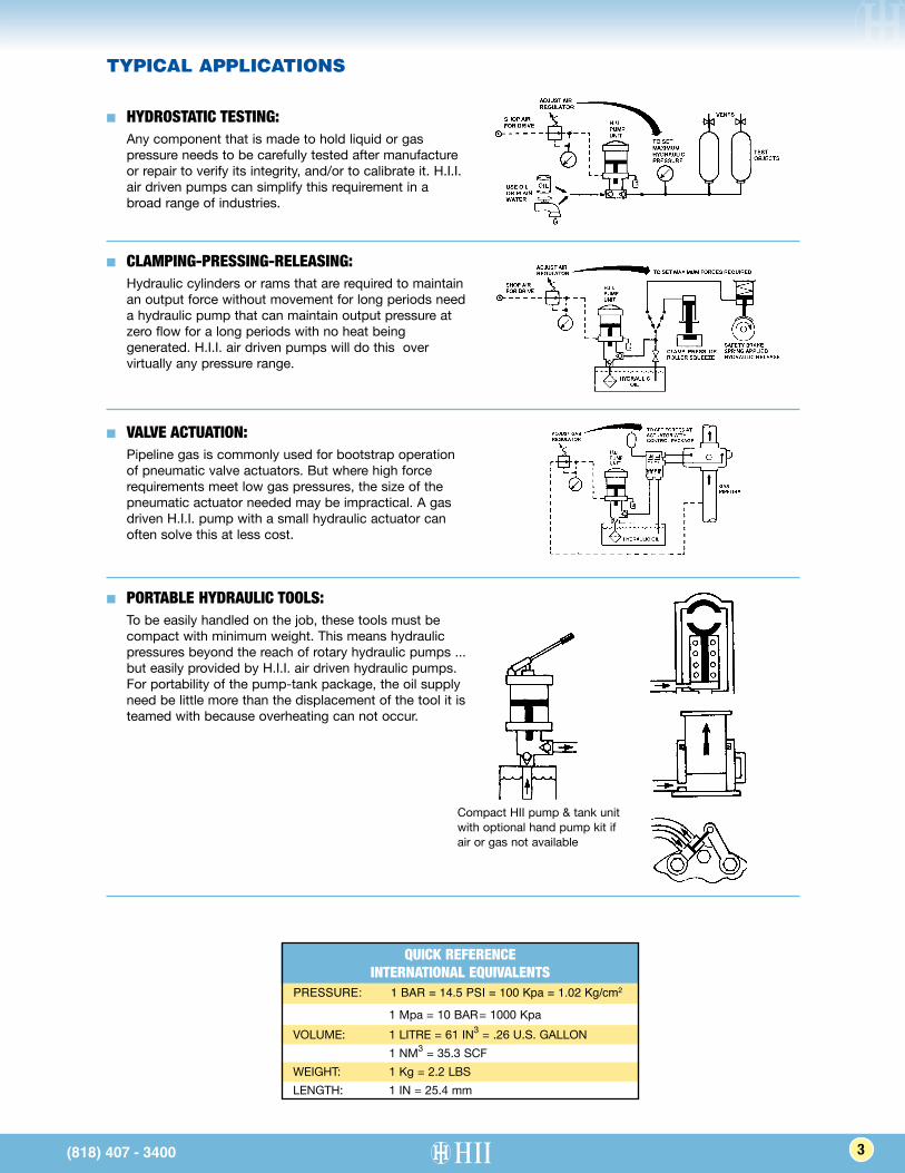
■ HYDROSTATIC TESTING: Any component that is made to hold liquid or gas
pressure needs to be carefully tested after manufacture or repair to verify its integrity, and/or to calibrate it. H.I.I. air driven pumps can simplify this requirement in a broad range of industries.
■ CLAMPING-PRESSING-RELEASING: Hydraulic cylinders or rams that are required to maintain
an output force without movement for long periods need a hydraulic pump that can maintain output pressure at zero flow for a long periods with no heat being generated. H.I.I. air driven pumps will do this over virtually any pressure range.
■ VALVE ACTUATION: Pipeline gas is commonly used for bootstrap operation
of pneumatic valve actuators. But where high force requirements meet low gas pressures, the size of the pneumatic actuator needed may be impractical. A gas driven H.I.I. pump with a small hydraulic actuator can often solve this at less cost.
■ PORTABLE HYDRAULIC TOOLS: To be easily handled on the job, these tools must be
compact with minimum weight. This means hydraulic pressures beyond the reach of rotary hydraulic pumps ... but easily provided by H.I.I. air driven hydraulic pumps. For portability of the pump-tank package, the oil supply need be little more than the displacement of the tool it is teamed with because overheating can not occur.
Compact HII pump & tank unit with optional hand pump kit if air or gas not available
TYPICAL APPLICATIONS
(818) 407 - 3400 3(818) 407 - 3400
QUICK REFERENCEINTERNATIONAL EQUIVALENTS
PRESSURE: 1 BAR = 14.5 PSI = 100 Kpa = 1.02 Kg/cm2
1 Mpa = 10 BAR = 1000 KpaVOLUME: 1 LITRE = 61 IN3 = .26 U.S. GALLON 1 NM3 = 35.3 SCFWEIGHT: 1 Kg = 2.2 LBSLENGTH: 1 IN = 25.4 mm
HYDRAULICS INTERNATIONAL, INC. (818) 407-3400
Volume DisplacementPer Cycle
Model with Ratio Dash Number1
Item#
InletPSI BAR CU. IN. M.L Outlet
Liquid Port Detail 6
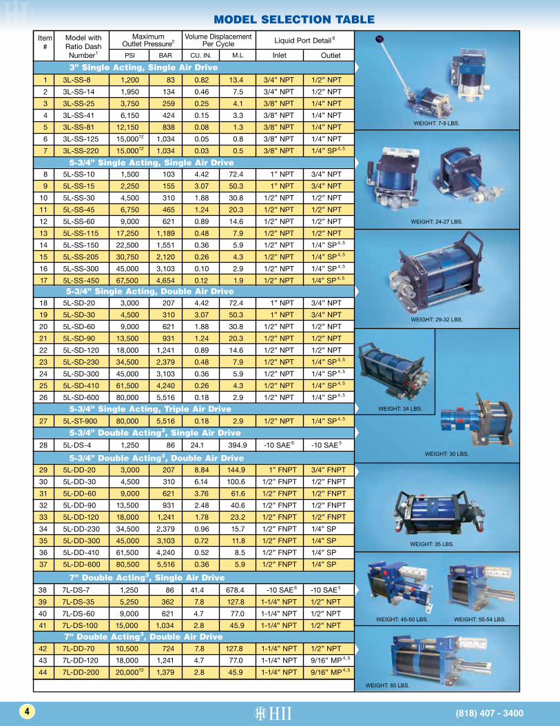
7” Double Acting3, Double Air Drive
7” Double Acting3, Single Air Drive
MODEL SELECTION TABLE
5-3/4” Single Acting, Triple Air Drive
5-3/4” Double Acting3, Single Air Drive
5-3/4” Double Acting3, Double Air Drive
WEIGHT: 7-9 LBS.
WEIGHT: 24-27 LBS.
WEIGHT: 29-32 LBS.
WEIGHT: 30 LBS.
WEIGHT: 45-50 LBS.
WEIGHT: 35 LBS.
WEIGHT: 50-54 LBS.
WEIGHT: 85 LBS.
WEIGHT: 34 LBS.
5-3/4” Single Acting, Double Air Drive
3” Single Acting, Single Air Drive
5-3/4” Single Acting, Single Air Drive
MaximumOutlet Pressure2
4 (818) 407 - 3400
42 7L-DD-70 10,500 724 7.8 127.8 1-1/4” NPT 1/2” NPT 43 7L-DD-120 18,000 1,241 4.7 77.0 1-1/4” NPT 9/16” MP 4, 5 44 7L-DD-200 20,00012 1,379 2.8 45.9 1-1/4” NPT 9/16” MP 4, 5
38 7L-DS-7 1,250 86 41.4 678.4 -10 SAE 6 -10 SAE 5
39 7L-DS-35 5,250 362 7.8 127.8 1-1/4” NPT 1/2” NPT 40 7L-DS-60 9,000 621 4.7 77.0 1-1/4” NPT 1/2” NPT 41 7L-DS-100 15,000 1,034 2.8 45.9 1-1/4” NPT 1/2” NPT
29 5L-DD-20 3,000 207 8.84 144.9 1” FNPT 3/4” FNPT 30 5L-DD-30 4,500 310 6.14 100.6 1/2” FNPT 1/2” FNPT 31 5L-DD-60 9,000 621 3.76 61.6 1/2” FNPT 1/2” FNPT 32 5L-DD-90 13,500 931 2.48 40.6 1/2” FNPT 1/2” FNPT 33 5L-DD-120 18,000 1,241 1.78 23.2 1/2” FNPT 1/2” FNPT 34 5L-DD-230 34,500 2,379 0.96 15.7 1/2” FNPT 1/4” SP 35 5L-DD-300 45,000 3,103 0.72 11.8 1/2” FNPT 1/4” SP 36 5L-DD-410 61,500 4,240 0.52 8.5 1/2” FNPT 1/4” SP 37 5L-DD-600 80,500 5,516 0.36 5.9 1/2” FNPT 1/4” SP
18 5L-SD-20 3,000 207 4.42 72.4 1” NPT 3/4” NPT 19 5L-SD-30 4,500 310 3.07 50.3 1” NPT 3/4” NPT 20 5L-SD-60 9,000 621 1.88 30.8 1/2” NPT 1/2” NPT 21 5L-SD-90 13,500 931 1.24 20.3 1/2” NPT 1/2” NPT 22 5L-SD-120 18,000 1,241 0.89 14.6 1/2” NPT 1/2” NPT 23 5L-SD-230 34,500 2,379 0.48 7.9 1/2” NPT 1/4” SP 4, 5
24 5L-SD-300 45,000 3,103 0.36 5.9 1/2” NPT 1/4” SP 4, 5
25 5L-SD-410 61,500 4,240 0.26 4.3 1/2” NPT 1/4” SP 4, 5
26 5L-SD-600 80,000 5,516 0.18 2.9 1/2” NPT 1/4” SP 4, 5
27 5L-ST-900 80,000 5,516 0.18 2.9 1/2” NPT 1/4” SP 4, 5
28 5L-DS-4 1,250 86 24.1 394.9 -10 SAE 6 -10 SAE 5
1 3L-SS-8 1,200 83 0.82 13.4 3/4” NPT 1/2” NPT 2 3L-SS-14 1,950 134 0.46 7.5 3/4” NPT 1/2” NPT 3 3L-SS-25 3,750 259 0.25 4.1 3/8” NPT 1/4” NPT 4 3L-SS-41 6,150 424 0.15 3.3 3/8” NPT 1/4” NPT 5 3L-SS-81 12,150 838 0.08 1.3 3/8” NPT 1/4” NPT 6 3L-SS-125 15,00012 1,034 0.05 0.8 3/8” NPT 1/4” NPT 7 3L-SS-220 15,00012 1,034 0.03 0.5 3/8” NPT 1/4” SP 4, 5
8 5L-SS-10 1,500 103 4.42 72.4 1” NPT 3/4” NPT 9 5L-SS-15 2,250 155 3.07 50.3 1” NPT 3/4” NPT 10 5L-SS-30 4,500 310 1.88 30.8 1/2” NPT 1/2” NPT 11 5L-SS-45 6,750 465 1.24 20.3 1/2” NPT 1/2” NPT 12 5L-SS-60 9,000 621 0.89 14.6 1/2” NPT 1/2” NPT 13 5L-SS-115 17,250 1,189 0.48 7.9 1/2” NPT 1/2” NPT 14 5L-SS-150 22,500 1,551 0.36 5.9 1/2” NPT 1/4” SP 4, 5
15 5L-SS-205 30,750 2,120 0.26 4.3 1/2” NPT 1/4” SP 4, 5
16 5L-SS-300 45,000 3,103 0.10 2.9 1/2” NPT 1/4” SP 4, 5
17 5L-SS-450 67,500 4,654 0.12 1.9 1/2” NPT 1/4” SP 4, 5
(818) 407 - 3400
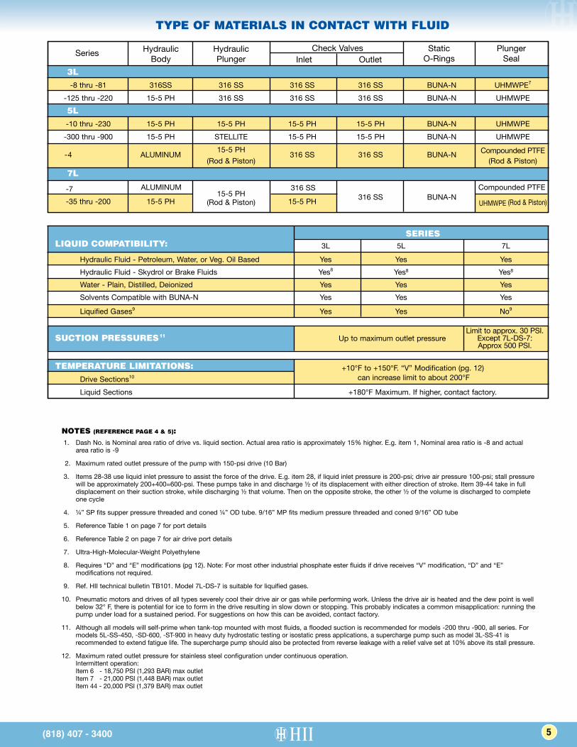
TYPE OF MATERIALS IN CONTACT WITH FLUID
Series HydraulicBody
HydraulicPlunger Inlet Outlet
Static O-Rings
PlungerSeal
Check Valves
3L -8 thru -81 316SS 316 SS 316 SS 316 SS BUNA-N UHMWPE7
-125 thru -220 15-5 PH 316 SS 316 SS 316 SS BUNA-N UHMWPE 5L -10 thru -230 15-5 PH 15-5 PH 15-5 PH 15-5 PH BUNA-N UHMWPE -300 thru -900 15-5 PH STELLITE 15-5 PH 15-5 PH BUNA-N UHMWPE -4 ALUMINUM 15-5 PH 316 SS 316 SS BUNA-N Compounded PTFE (Rod & Piston) (Rod & Piston)
7L
-35 thru -200 15-5 PH 15-5 PH 15-5 PH 316 SS BUNA-N
(Rod & Piston) UHMWPE (Rod & Piston)
TEMPERATURE LIMITATIONS: +10°F to +150°F. “V” Modification (pg. 12) Drive Sections10
can increase limit to about 200°F
Liquid Sections +180°F Maximum. If higher, contact factory.
ALUMINUM 316 SS Compounded PTFE-7
SERIESLIQUID COMPATIBILITY: 3L 5L 7L
Hydraulic Fluid - Petroleum, Water, or Veg. Oil Based Yes Yes Yes Hydraulic Fluid - Skydrol or Brake Fluids Yes8 Yes8 Yes8 Water - Plain, Distilled, Deionized Yes Yes Yes Solvents Compatible with BUNA-N Yes Yes Yes
Liquified Gases9 Yes Yes No9
SUCTION PRESSURES11 Up to maximum outlet pressureLimit to approx. 30 PSI.
Except 7L-DS-7: Approx 500 PSI.
NOTES (REFERENCE PAGE 4 & 5): 1. Dash No. is Nominal area ratio of drive vs. liquid section. Actual area ratio is approximately 15% higher. E.g. item 1, Nominal area ratio is -8 and actual
area ratio is -9
2. Maximum rated outlet pressure of the pump with 150-psi drive (10 Bar)
3. Items 28-38 use liquid inlet pressure to assist the force of the drive. E.g. item 28, if liquid inlet pressure is 200-psi; drive air pressure 100-psi; stall pressure will be approximately 200+400=600-psi. These pumps take in and discharge ½ of its displacement with either direction of stroke. Item 39-44 take in full displacement on their suction stroke, while discharging ½ that volume. Then on the opposite stroke, the other ½ of the volume is discharged to complete one cycle
4. ¼” SP fits supper pressure threaded and coned ¼” OD tube. 9/16” MP fits medium pressure threaded and coned 9/16” OD tube
5. Reference Table 1 on page 7 for port details
6. Reference Table 2 on page 7 for air drive port details
7. Ultra-High-Molecular-Weight Polyethylene
8. Requires “D” and “E” modifications (pg 12). Note: For most other industrial phosphate ester fluids if drive receives “V” modification, “D” and “E” modifications not required.
9. Ref. HII technical bulletin TB101. Model 7L-DS-7 is suitable for liquified gases.
10. Pneumatic motors and drives of all types severely cool their drive air or gas while performing work. Unless the drive air is heated and the dew point is well below 32° F, there is potential for ice to form in the drive resulting in slow down or stopping. This probably indicates a common misapplication: running the pump under load for a sustained period. For suggestions on how this can be avoided, contact factory.
11. Although all models will self-prime when tank-top mounted with most fluids, a flooded suction is recommended for models -200 thru -900, all series. For models 5L-SS-450, -SD-600, -ST-900 in heavy duty hydrostatic testing or isostatic press applications, a supercharge pump such as model 3L-SS-41 is recommended to extend fatigue life. The supercharge pump should also be protected from reverse leakage with a relief valve set at 10% above its stall pressure.
12. Maximum rated outlet pressure for stainless steel configuration under continuous operation. Intermittent operation: Item 6 - 18,750 PSI (1,293 BAR) max outlet Item 7 - 21,000 PSI (1,448 BAR) max outlet Item 44 - 20,000 PSI (1,379 BAR) max outlet
5
HYDRAULICS INTERNATIONAL, INC. (818) 407-3400
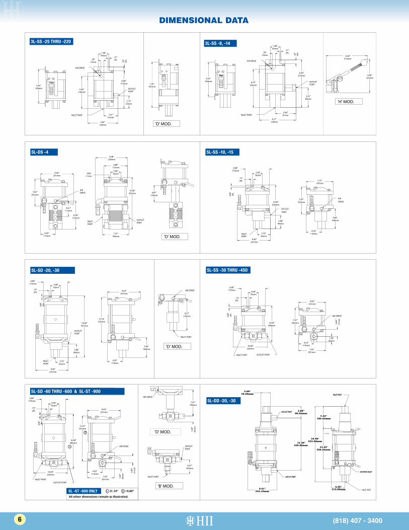
DIMENSIONAL DATA
21.34”1 18.60”2
All other dimensions remain as illustrated.
6 (818) 407 - 3400
3L-SS -25 THRU -220 3L-SS -8, -14
5L-DS -4
5L-SD -20, -30
5L-SD -60 THRU -600 & 5L-ST -900
5L -ST -900 ONLY
5L-SS -30 THRU -450
5L-DD -20, -30
5L-SS -10, -15
HYDRAULICS INTERNATIONAL, INC. (818) 407-3400
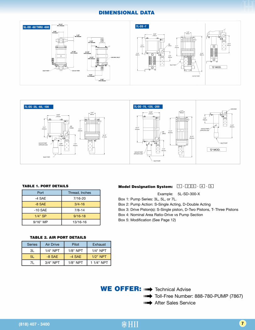
DIMENSIONAL DATA
(818) 407 - 3400
5L-SD -60 THRU -600 & 5L-ST -900
1
21.34”1 18.60”2
ALL OTHER DIMENSIONS REMAIN AS ILLUSTRATED.
5L -ST -900 ONLY
2
5L-DD-60 thru -600
(818) 407 - 3400
TABLE 1. PORT DETAILS
Port Thread, Inches -4 SAE 7/16-20 -8 SAE 3/4-16 -10 SAE 7/8-14 1/4" SP 9/16-18 9/16" MP 13/16-16
TABLE 2. AIR PORT DETAILS
Series Air Drive Pilot Exhaust 3L 1/4" NPT 1/8" NPT 1/4" NPT 5L -8 SAE -4 SAE 1/2" NPT 7L 3/4" NPT 1/8" NPT 1 1/4" NPT
1 - 2 3 - 4 - 5Model Designation System:
Example: 5L-SD-300-XBox 1: Pump Series: 3L, 5L, or 7L.Box 2: Pump Action: S-Single Acting, D-Double ActingBox 3: Drive Piston(s): S-Single piston, D-Two Pistons, T- Three PistonsBox 4: Nominal Area Ratio-Drive vs Pump SectionBox 5: Modification (See Page 12)
7
5L-DD -60 THRU -600
7L-DS -35, -60, -100 7L-DD -70, -120, -200
7L-DS -7
WE OFFER: ➟ Technical Advise ➟ Toll-Free Number: 888-780-PUMP (7867) ➟ After Sales Service
HYDRAULICS INTERNATIONAL, INC. (818) 407-3400
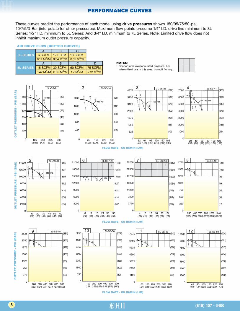
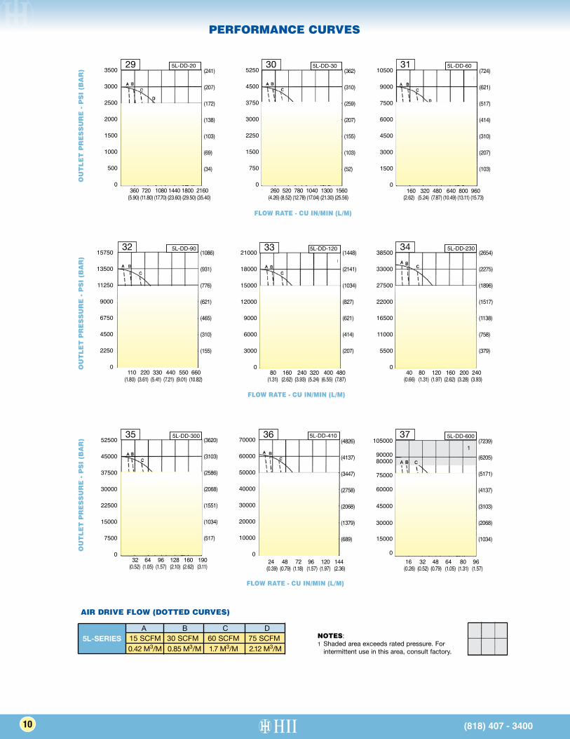
PERFORMANCE CURVES
A B C
A B C D
6 SCFM 12 SCFM 18 SCFM 0.17 M3/M 0.34 M3/M 0.51 M3/M
15 SCFM 30 SCFM 60 SCFM 75 SCFM 0.42 M3/M 0.85 M3/M 1.7 M3/M 2.12 M3/M
AIR DRIVE FLOW (DOTTED CURVES)
3L-SERIES
5L-SERIESNOTES: 1 Shaded area exceeds rated pressure. For
intermittent use in this area, consult factory.
These curves predict the performance of each model using drive pressures shown 150/95/75/50-psi, 10/7/5/3-Bar (interpolate for other pressures). Maximum flow points presume 1/4” I.D. drive line minimum to 3L Series; 1/2” I.D. minimum to 5L Series; And 3/4” I.D. minimum to 7L Series. Note: Limited drive flow does not inhibit maximum outlet pressure capacity.
160 320 480 640 800 960
2625
2250
1875
1500
1125
750
375
0
9 5L-SS-15
100 200 300 400 500 600
5250
4500
3750
3000
2250
1500
750
0
10 5L-SS-30
65 130 195 260 325 390
7875
6750
5625
4500
3375
2250
1125
0
11 5L-SS-4510500
9000
7500
6000
4500
3000
1500
045 90 135 180 225 270
12 5L-SS-60
OU
TL
ET
PR
ES
SU
RE
- P
SI
(BA
R)
OU
TL
ET
PR
ES
SU
RE
- P
SI
(BA
R) 5
14000
12000
10000
8000
6000
4000
2000
010 20 30 40 50 60
3L-SS-81
121000
18000
15000
12000
9000
6000
3000
06 12 18 24 30 36
3L-SS-12561
26250
22500
18750
15000
11250
7500
3750
04 8 12 16 20 24
7 3L-SS-220 1750
1500
1250
1000
750
500
250
0240 480 720 960 1200 1440
8 5L-SS-10
OU
TL
ET
PR
ES
SU
RE
- P
SI
(BA
R)
FLOW RATE - CU IN/MIN
7000
6000
5000
4000
3000
2000
1000
020 40 60 80 100 120
4 3L-SS-4134375
3750
3125
2500
1875
1250
625
032 64 96 128 160 192
3L-SS-253L-SS-14
300225150750
400
800
1200
1600
2000
2
95
75
50
CBA
150 PSI
(138)
(110)
(83)
(55)
(28)
(1.23) (2.46) (3.69) (4.92)
2 3L-SS-143L-SS-8
500375250
(83)
(69)
(55)
(41)
(28)
(14)
125(2.05) (4.1) (6.2) (8.2)
0
200
400
600
800
1000
1200
1
150 PSI
95
75
50
C
BA
1 3L-SS-8
8 (818) 407 - 3400
(.52) (1.05) (1.57) (2.10) (2.62) (3.15) (.33) (.66) (.98) (1.31) (1.64) (1.97)
(302)
(259)
(215)
(172)
(129)
(86)
(43)
(483)
(414)
(345)
(276)
(207)
(138)
(69)
(.16) (.33) (.49) (.66) (.82) (.98) (.10) (.20) (.29) (.39) (.49) (.59) (.07) (.13) (.20) (.26) (.33) (.39) (3.93) (7.87) (11.80) (15.73) (19.66) (23.60)
(2.62) (5.24) (7.87) (10.49) (13.11) (15.73) (1.64) (3.28) (4.92) (6.55) (8.19) (9.83) (1.07) (2.13) (3.20) (4.26) (5.33) (6.39) (0.74) (1.47) (2.21) (2.95) (3.69) (4.42)
(965)
(827)
(689)
(552)
(414)
(276)
(138)
(1448)
(1241)
(1034)
(827)
(621)
(414)
(207)
(1810)
(1551)
(1293)
(1034)
(776)
(517)
(259)
(121)
(103)
(86)
(69)
(52)
(34)
(17)
(181)
(155)
(129)
(103)
(78)
(52)
(26)
(362)
(310)
(259)
(207)
(155)
(103)
(52)
(543)
(465)
(388)
(310)
(233)
(155)
(78)
(724)
(621)
(517)
(414)
(310)
(207)
(102)
FLOW RATE - CU IN/MIN (L/M)
FLOW RATE - CU IN/MIN (L/M)
FLOW RATE - CU IN/MIN (L/M)
HYDRAULICS INTERNATIONAL, INC. (818) 407-3400
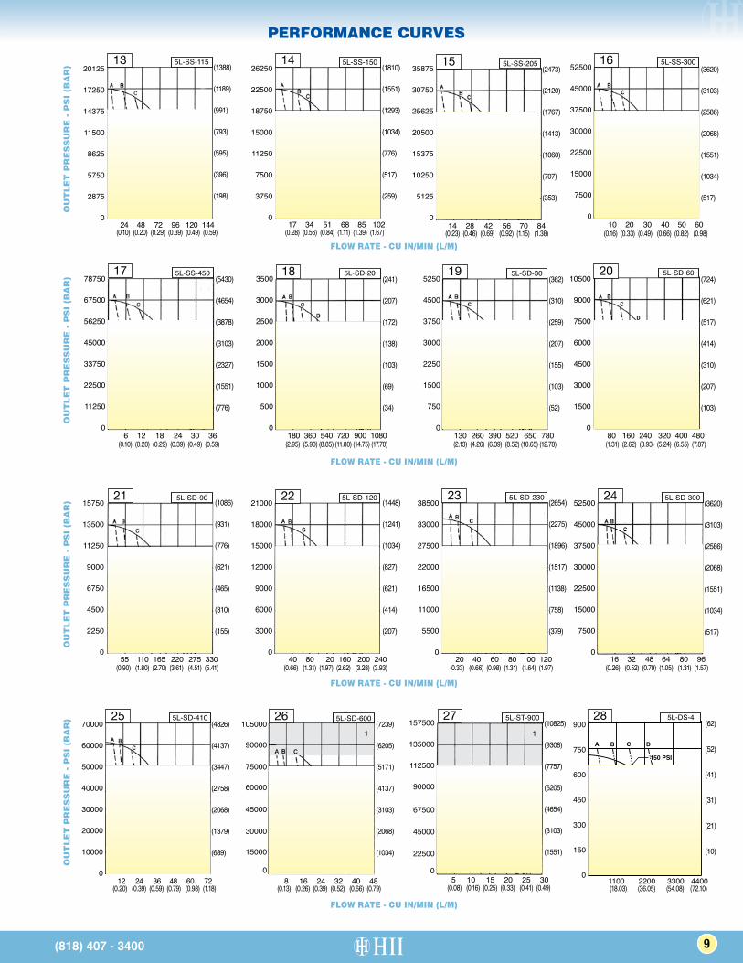
PERFORMANCE CURVES
52500
45000
37500
30000
22500
15000
7500
010 20 30 40 50 60
16 5L-SS-300
14 28 42 56 70 84
35875
30750
25625
20500
15375
10250
5125
0
15 5L-SS-205
17 34 51 68 85 102
26250
22500
18750
15000
11250
7500
3750
0
14 5L-SS-150
24 48 72 96 120 144
20125
17250
14375
11500
8625
5750
2875
0
13 5L-SS-115 O
UT
LE
T P
RE
SS
UR
E -
PS
I (B
AR
)
52500
45000
37500
30000
22500
15000
7500
016 32 48 64 80 96
24 5L-SD-30038500
33000
27500
22000
16500
11000
5500
020 40 60 80 100 120
23 5L-SD-23021000
18000
15000
12000
9000
6000
3000
040 80 120 160 200 240
22 5L-SD-12015750
13500
11250
9000
6750
4500
2250
055 110 165 220 275 330
21 5L-SD-90
OU
TL
ET
PR
ES
SU
RE
- P
SI
(BA
R)
78750
67500
56250
45000
33750
22500
11250
06 12 18 24 30 36
17 5L-SS-4503500
3000
2500
2000
1500
1000
500
0180 360 540 720 900 1080
18 5L-SD-205250
4500
3750
3000
2250
1500
750
0130 260 390 520 650 780
19 5L-SD-3010500
9000
7500
6000
4500
3000
1500
080 160 240 320 400 480
20 5L-SD-60
OU
TL
ET
PR
ES
SU
RE
- P
SI
(BA
R)
OU
TL
ET
PR
ES
SU
RE
- P
SI
(BA
R) 70000
60000
50000
40000
30000
20000
10000
012 24 36 48 60 72
25 5L-SD-410105000
90000
75000
60000
45000
30000
15000
08 16 24 32 40 48
1
26 5L-SD-600 157500
135000
112500
90000
67500
45000
22500
05 10 15 20 25 30
1
27 5L-ST-900
A B C D A B C DA B C D
A B C D
A B C D
A B C D
A B C D
80
60
100 PSI
80
60
100 PSI
150 PSI
150 PSI 150 PSI 150 PSI
80
60
100 PSI
95
75
150 PSI
50
80
100 PSI
60
80
100 PSI
60
80
100 PSI
60
150 PSI
900
750
600
450
300
150
01100 2200 3300 4400
28 5L-DS-4
(818) 407 - 3400
(0.10) (0.20) (0.29) (0.39) (0.49) (0.59)
(0.10) (0.20) (0.29) (0.39) (0.49) (0.59)
(0.90) (1.80) (2.70) (3.61) (4.51) (5.41) (0.66) (1.31) (1.97) (2.62) (3.28) (3.93) (0.33) (0.66) (0.98) (1.31) (1.64) (1.97) (0.26) (0.52) (0.79) (1.05) (1.31) (1.57)
(0.20) (0.39) (0.59) (0.79) (0.98) (1.18) (0.13) (0.26) (0.39) (0.52) (0.66) (0.79) (0.08) (0.16) (0.25) (0.33) (0.41) (0.49) (18.03) (36.05) (54.08) (72.10)
(2.95) (5.90) (8.85) (11.80) (14.75) (17.70) (2.13) (4.26) (6.39) (8.52) (10.65) (12.78) (1.31) (2.62) (3.93) (5.24) (6.55) (7.87)
(0.28) (0.56) (0.84) (1.11) (1.39) (1.67) (0.23) (0.46) (0.69) (0.92) (1.15) (1.38) (0.16) (0.33) (0.49) (0.66) (0.82) (0.98)
(1388)
(1189)
(991)
(793)
(595)
(396)
(198)
(5430)
(4654)
(3878)
(3103)
(2327)
(1551)
(776)
(1086)
(931)
(776)
(621)
(465)
(310)
(155)
(1448)
(1241)
(1034)
(827)
(621)
(414)
(207)
(2654)
(2275)
(1896)
(1517)
(1138)
(758)
(379)
(3620)
(3103)
(2586)
(2068)
(1551)
(1034)
(517)
(4826)
(4137)
(3447)
(2758)
(2068)
(1379)
(689)
(7239)
(6205)
(5171)
(4137)
(3103)
(2068)
(1034)
(10825)
(9308)
(7757)
(6205)
(4654)
(3103)
(1551)
(62)
(52)
(41)
(31)
(21)
(10)
(241)
(207)
(172)
(138)
(103)
(69)
(34)
(362)
(310)
(259)
(207)
(155)
(103)
(52)
(724)
(621)
(517)
(414)
(310)
(207)
(103)
(1810)
(1551)
(1293)
(1034)
(776)
(517)
(259)
(2473)
(2120)
(1767)
(1413)
(1060)
(707)
(353)
(3620)
(3103)
(2586)
(2068)
(1551)
(1034)
(517)
FLOW RATE - CU IN/MIN (L/M)
FLOW RATE - CU IN/MIN (L/M)
FLOW RATE - CU IN/MIN (L/M)
FLOW RATE - CU IN/MIN (L/M)
9
3500
3000
2500
2000
1500
1000
500
0360 720 1080 1440 1800 2160
29 5L-DD-205250
4500
3750
3000
2250
1500
750
0260 520 780 1040 1300 1560
30 5L-DD-3010500
9000
7500
6000
4500
3000
1500
0160 320 480 640 800 960
31 5L-DD-60
52500
45000
37500
30000
22500
15000
7500
0 32 64 96 128 160 190
35 5L-DD-300
38500
33000
27500
22000
16500
11000
5500
040 80 120 160 200 240
34 5L-DD-23021000
18000
15000
12000
9000
6000
3000
080 160 240 320 400 480
33 5L-DD-12015750
13500
11250
9000
6750
4500
2250
0110 220 330 440 550 660
32 5L-DD-90
70000
60000
50000
40000
30000
20000
10000
024 48 72 96 120 144
36 5L-DD-410105000
9000080000
75000
60000
45000
30000
15000
016 32 48 64 80 96
1
37 5L-DD-600
PERFORMANCE CURVES
10 (818) 407 - 3400
OU
TL
ET
PR
ES
SU
RE
- P
SI
(BA
R)
OU
TL
ET
PR
ES
SU
RE
- P
SI
(BA
R)
OU
TL
ET
PR
ES
SU
RE
- P
SI
(BA
R)
FLOW RATE - CU IN/MIN (L/M)
FLOW RATE - CU IN/MIN (L/M)
FLOW RATE - CU IN/MIN (L/M)
NOTES: 1 Shaded area exceeds rated pressure. For
intermittent use in this area, consult factory.
(241)
(207)
(172)
(138)
(103)
(69)
(34)
(362)
(310)
(259)
(207)
(155)
(103)
(52)
(724)
(621)
(517)
(414)
(310)
(207)
(103)
(1086)
(931)
(776)
(621)
(465)
(310)
(155)
(3620)
(3103)
(2586)
(2068)
(1551)
(1034)
(517)
(4826)
(4137)
(3447)
(2758)
(2068)
(1379)
(689)
(7239)
(6205)
(5171)
(4137)
(3103)
(2068)
(1034)
(1448)
(2141)
(1034)
(827)
(621)
(414)
(207)
(2654)
(2275)
(1896)
(1517)
(1138)
(758)
(379)
(5.90) (11.80) (17.70) (23.60) (29.50) (35.40) (4.26) (8.52) (12.78) (17.04) (21.30) (25.56) (2.62) (5.24) (7.87) (10.49) (13.11) (15.73)
(1.80) (3.61) (5.41) (7.21) (9.01) (10.82)
(0.52) (1.05) (1.57) (2.10) (2.62) (3.11) (0.39) (0.79) (1.18) (1.57) (1.97) (2.36) (0.26) (0.52) (0.79) (1.05) (1.31) (1.57)
(1.31) (2.62) (3.93) (5.24) (6.55) (7.87) (0.66) (1.31) (1.97) (2.62) (3.28) (3.93)
AIR DRIVE FLOW (DOTTED CURVES)
A B C D 15 SCFM 30 SCFM 60 SCFM 75 SCFM 0.42 M3/M 0.85 M3/M 1.7 M3/M 2.12 M3/M
5L-SERIES
HYDRAULICS INTERNATIONAL, INC. (818) 407-3400
A B C D A B C DA B C D
A B C D
A B C D
A B C D
A B C D
80
60
100 PSI
80
60
100 PSI
150 PSI
150 PSI 150 PSI 150 PSI
80
60
100 PSI
95
75
150 PSI
50
80
100 PSI
60
80
100 PSI
60
80
100 PSI
60
150 PSI
8000
6000
4000
2000
0 200 400 600 800 1000
40 7L-DS-60
A B C D A B C DA B C D
A B C D
A B C D
A B C D
A B C D
80
60
100 PSI
80
60
100 PSI
150 PSI
150 PSI 150 PSI 150 PSI
80
60
100 PSI
95
75
150 PSI
50
80
100 PSI
60
80
100 PSI
60
80
100 PSI
60
150 PSI
5000
4000
3000
2000
1000
0 300 600 900 1200 1500
39 7L-DS-357L-DS-7
200015001000500040
200
400
600
800
1000
1200 29
95
75
150 PSI
DCBA
50
1200
1000
800
600
400
200
0 1500 3000 4500 6000
38 7L-DS-7
A B C D A B C DA B C D
A B C D
A B C D
A B C D
A B C D
80
60
100 PSI
80
60
100 PSI
150 PSI
150 PSI 150 PSI 150 PSI
80
60
100 PSI
95
75
150 PSI
50
80
100 PSI
60
80
100 PSI
60
80
100 PSI
60
150 PSI10000
8000
6000
4000
2000
0 300 600 900 1200 1500
42 7L-DD-70
A B C D A B C DA B C D
A B C D
A B C D
A B C D
A B C D
80
60
100 PSI
80
60
100 PSI
150 PSI
150 PSI 150 PSI 150 PSI
80
60
100 PSI
95
75
150 PSI
50
80
100 PSI
60
80
100 PSI
60
80
100 PSI
60
150 PSI
17500
14000
10500
7000
3500
0240 480 720 960
43 7L-DD-120
0
10
181716151413121110987654321
20
30
40
50
60
70
80
90
100
110
120
PSI X 1000
PERCENT
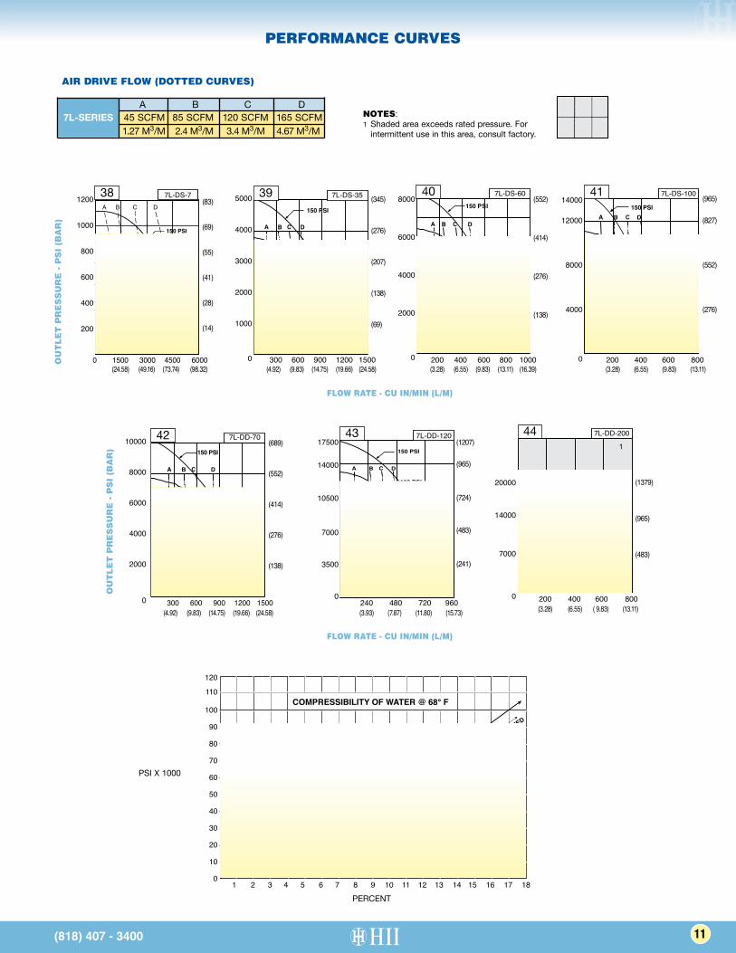
SOURCE: MARKS' STANDARD HANDBOOK FOR MECHANICAL ENGINEERS - 9TH ED.
EXTRAPOLATED
COMPRESSIBILITY OF WATER @ 68° F
120
110
100
90
80
70
60
50
40
30
20
10
01 2 3 4 5 6 7 8 9 10 11 12 13 14 15 16 17 18
PSI X 1000
A B C D A B C DA B C D
A B C D
A B C D
A B C D
A B C D
80
60
100 PSI
80
60
100 PSI
150 PSI
150 PSI 150 PSI 150 PSI
80
60
100 PSI
95
75
150 PSI
50
80
100 PSI
60
80
100 PSI
60
80
100 PSI
60
150 PSI 1
20000
14000
7000
0 200 400 600 800
44 7L-DD-200
PERFORMANCE CURVES
(818) 407 - 3400
OU
TL
ET
PR
ES
SU
RE
- P
SI
(BA
R)
OU
TL
ET
PR
ES
SU
RE
- P
SI
(BA
R)
FLOW RATE - CU IN/MIN (L/M)
FLOW RATE - CU IN/MIN (L/M)
NOTES: 1 Shaded area exceeds rated pressure. For
intermittent use in this area, consult factory.
PERCENT
(83)
(69)
(55)
(41)
(28)
(14)
(345)
(276)
(207)
(138)
(69)
(689)
(552)
(414)
(276)
(138)
(552)
(414)
(276)
(138)
(1379)
(965)
(483)
(1207)
(965)
(724)
(483)
(241)
(24.58) (49.16) (73.74) (98.32) (4.92) (9.83) (14.75) (19.66) (24.58)
(4.92) (9.83) (14.75) (19.66) (24.58)
(3.28) (6.55) (9.83) (13.11) (16.39)
(3.28) (6.55) ( 9.83) (13.11)
A B C D A B C DA B C D
A B C D
A B C D
A B C D
A B C D
80
60
100 PSI
80
60
100 PSI
150 PSI
150 PSI 150 PSI 150 PSI
80
60
100 PSI
95
75
150 PSI
50
80
100 PSI
60
80
100 PSI
60
80
100 PSI
60
150 PSI
14000
12000
8000
4000
0 200 400 600 800
41 7L-DS-100 (965)
(827)
(552)
(276)
(3.28) (6.55) (9.83) (13.11)
(3.93) (7.87) (11.80) (15.73)
A B C D 45 SCFM 85 SCFM 120 SCFM 165 SCFM 1.27 M3/M 2.4 M3/M 3.4 M3/M 4.67 M3/M
7L-SERIES
11
AIR DRIVE FLOW (DOTTED CURVES)
HYDRAULICS INTERNATIONAL, INC. (818) 407-3400
■ “B” Bottom Inlet. See dimensional data pg.6 and selection table pg. 4. This modification applies only to model item numbers 10 through 17 and 20 through 27. It is not available for item 28 or 29. It is standard on items 1-9, 18, 19, and 30-35 (which are not available with side inlet).
■ “D” Distance Piece. All series. Provides vented, dual seal protection where leakage or fumes from pumped fluid could attack the air drive section with only the single seal. Specify by adding -“D” after model number, e.g. Model 5L-SS-30-D. Double distance piece also available to protect air drive from some high or low temperature liquids. Specify by adding -“DD” after model number (5L Series only).
■ “E” EPR (Ethylene Propylene) Static Seals in Liquid Section Only. All series. Replaces all Buna static seals. Provides needed chemical resistance if liquid section is used with liquids incompatible with Buna, such as Skydrol. Standard Ultra High Molecular Weight Polyethylene plunger seal is not changed. It is compatible with Skydrol. Specify by adding -“E” after model number, e.g. Model 5L-SS-30-E. Note: -“D” Modification also highly recommended to protect air drive seals.
■ “H” Hand Pump Attachment. 3L Series only. Permits supplementary operation of the pump by hand. Useful in precise testing or emergency backup applications requiring a hand pump in addition to a power pump. Specify by adding “H” after model number, e.g. Model 3L-SS-41-H.
■ “L” Low Air Drive Pressure. 5L Series only. Allows operation of the pump with an air drive pressure regulated as low as 2-3 psi. Also includes “X” modification. External pilot pressure must be 30 psi or more. Specify by adding -“L” after model number, e.g. Model 5L-SS-30-L.
■ “P” Piped Exhaust. All series. Enables complete capture of exhaust air or gas from both the drive and pilot exhaust ports. Permits submerged operation inside hydraulic tanks, and/or piping exhausting gases out of the area for safety considerations. Exhaust ports for drive and pilot are 1/4” NPT and 1/8” NPT respectively on the 3L and 1-1/4” & 1/8” NPT on the 7L Series. On the 5L Series, drive and pilot exhaust are joined at a 1/2” NPT outlet. Specify by adding -“P” after the model number, e.g. 5L-SS-30-P.
■ “S” Single Stroke. 5L Series and 3L series except -4. Useful for testing, metering or single stroke intensifier type hydraulic applications. Pump cycles once when momentary air pulse is applied to 1/8” NPT “S” port. Pump will not cycle otherwise. Specify by adding “S” after model number, e.g. Model 5L-SS-30-S.
■ “RC” Retract Command. 5L Series only except -4. Similar to “S”. Momentary air pulse will put pump on retract stroke; otherwise pump cycles normally. Used for close control of test pressures. Precision air regulator recommended.
■ “V” Viton Sealed Drive Section. 3L, 5L and 7L Series. Replaces all Buna static and dynamic seals. Provides needed chemical resistance if drive air or gas has entrained substances incompatible with Buna, such as hydrogen sulfide or some synthetic lubricants sometimes found in plant air compressors. Specify by adding -“V” after model number, e.g. Model 5L-SS-30-V.
■ “V1” Viton Static O-rings in Liquid Section. For higher temperatures than advisable for Buna, and for extra resistance to some chemicals. Specify by adding “V1” after model number.
■ “X” External Pilot Port on the Drive Section. All series. Enables start-stop control of drive with small shutoff valve. 3L, 7L Series 1/8” NPT, 5L Series -4 SAE (7/16”-20 threads). Specify by adding -“X” after model number, e.g. Model 5L-SS-30-X.
■ “R” Remove Return Spring in Drive Section. 3L Series only. For use with pressurized suction applications such as liquified gases. Improves filling action in the pump body on the suction stroke. Usually limited to -8 thru -41 ratios.
■ “T” 3 Way Cycling Spool in Drive. 5L Series only. For use with pressurized suction applications (As described for “R” Mod above).
STANDARD MODIFICATIONS
(818) 407 - 340012 (818) 407 - 3400
(818) 407 - 3400(818) 407 - 3400
HII POWER UNITS:
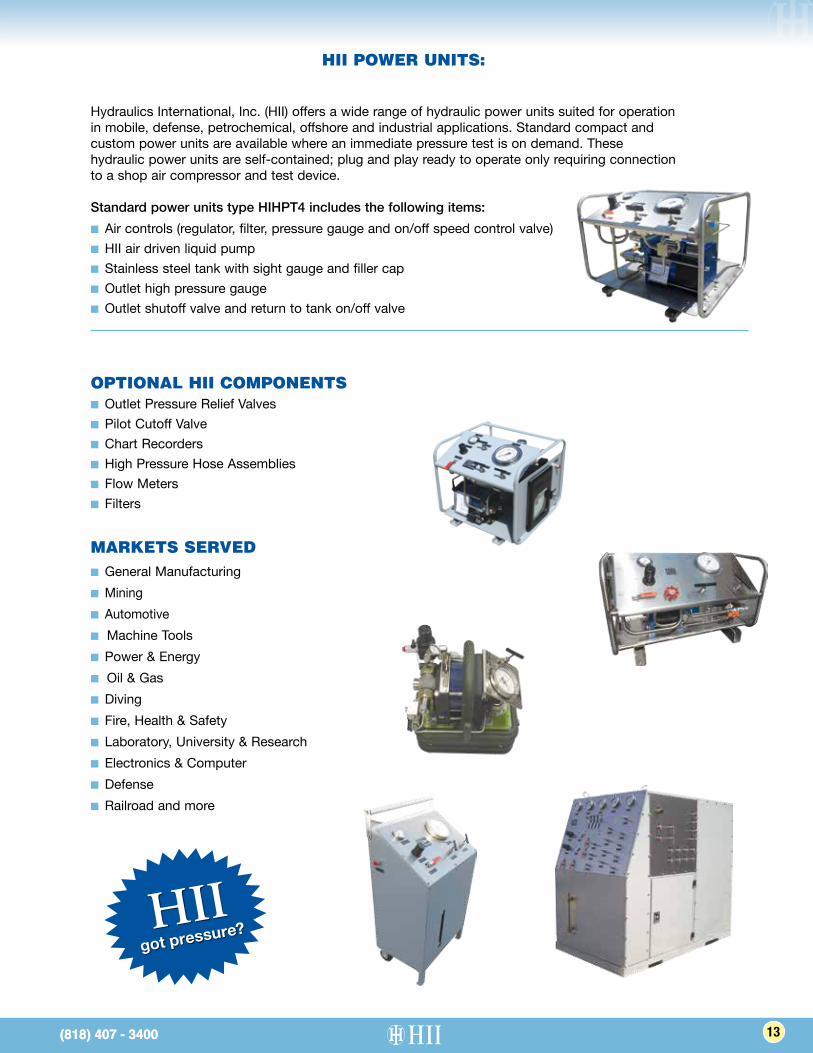
Hydraulics International, Inc. (HII) offers a wide range of hydraulic power units suited for operation in mobile, defense, petrochemical, offshore and industrial applications. Standard compact and custom power units are available where an immediate pressure test is on demand. These hydraulic power units are self-contained; plug and play ready to operate only requiring connection to a shop air compressor and test device.
Standard power units type HIHPT4 includes the following items: ■ Air controls (regulator, filter, pressure gauge and on/off speed control valve) ■ HII air driven liquid pump■ Stainless steel tank with sight gauge and filler cap■ Outlet high pressure gauge ■ Outlet shutoff valve and return to tank on/off valve
13
MARKETS SERVED■ General Manufacturing■ Mining■ Automotive■ Machine Tools■ Power & Energy■ Oil & Gas■ Diving■ Fire, Health & Safety■ Laboratory, University & Research■ Electronics & Computer■ Defense■ Railroad and more
OPTIONAL HII COMPONENTS■ Outlet Pressure Relief Valves■ Pilot Cutoff Valve■ Chart Recorders■ High Pressure Hose Assemblies■ Flow Meters■ Filters
got pressure?HII
Our products are designed, sourced and manufactured
in the U.S.A.
SYSTEMS■ Aircraft Ground Support Equipment
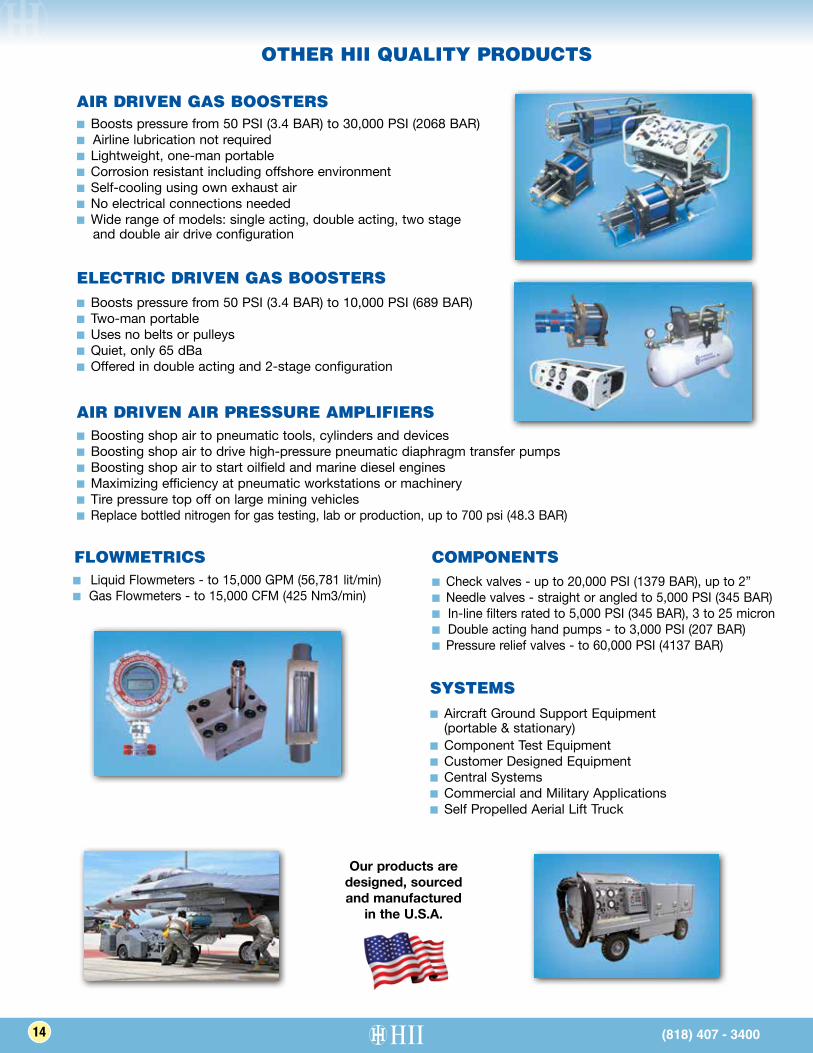
(portable & stationary)■ Component Test Equipment■ Customer Designed Equipment■ Central Systems■ Commercial and Military Applications■ Self Propelled Aerial Lift Truck
COMPONENTS■ Check valves - up to 20,000 PSI (1379 BAR), up to 2”■ Needle valves - straight or angled to 5,000 PSI (345 BAR)■ In-line filters rated to 5,000 PSI (345 BAR), 3 to 25 micron■ Double acting hand pumps - to 3,000 PSI (207 BAR)■ Pressure relief valves - to 60,000 PSI (4137 BAR)
AIR DRIVEN AIR PRESSURE AMPLIFIERS■ Boosting shop air to pneumatic tools, cylinders and devices■ Boosting shop air to drive high-pressure pneumatic diaphragm transfer pumps■ Boosting shop air to start oilfield and marine diesel engines■ Maximizing efficiency at pneumatic workstations or machinery■ Tire pressure top off on large mining vehicles■ Replace bottled nitrogen for gas testing, lab or production, up to 700 psi (48.3 BAR)
ELECTRIC DRIVEN GAS BOOSTERS■ Boosts pressure from 50 PSI (3.4 BAR) to 10,000 PSI (689 BAR)■ Two-man portable■ Uses no belts or pulleys■ Quiet, only 65 dBa■ Offered in double acting and 2-stage configuration
AIR DRIVEN GAS BOOSTERS■ Boosts pressure from 50 PSI (3.4 BAR) to 30,000 PSI (2068 BAR)■ Airline lubrication not required■ Lightweight, one-man portable■ Corrosion resistant including offshore environment■ Self-cooling using own exhaust air■ No electrical connections needed■ Wide range of models: single acting, double acting, two stage and double air drive configuration
(818) 407 - 3400 (818) 407 - 3400(818) 407 - 3400
FLOWMETRICS■ Liquid Flowmeters - to 15,000 GPM (56,781 lit/min)■ Gas Flowmeters - to 15,000 CFM (425 Nm3/min)
(818) 407 - 340014 (818) 407 - 3400
OTHER HII QUALITY PRODUCTS
HYDRAULICS INTERNATIONAL, INC. (818) 407-3400
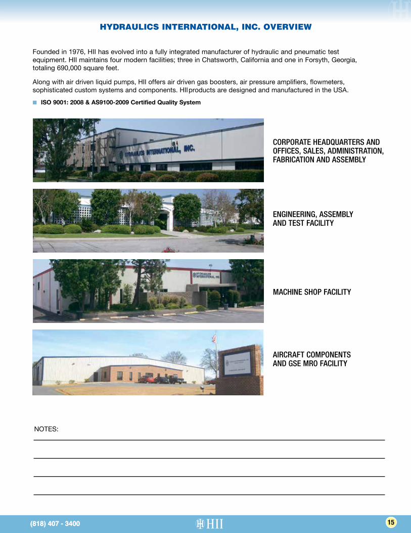
Founded in 1976, HII has evolved into a fully integrated manufacturer of hydraulic and pneumatic test equipment. HII maintains four modern facilities; three in Chatsworth, California and one in Forsyth, Georgia, totaling 690,000 square feet.
Along with air driven liquid pumps, HII offers air driven gas boosters, air pressure amplifiers, flowmeters, sophisticated custom systems and components. HII products are designed and manufactured in the USA.
■ ISO 9001: 2008 & AS9100-2009 Certified Quality System
NOTES:
CORPORATE HEADQUARTERS AND OFFICES, SALES, ADMINISTRATION, FABRICATION AND ASSEMBLY
MACHINE SHOP FACILITY
AIRCRAFT COMPONENTS AND GSE MRO FACILITY
ENGINEERING, ASSEMBLY AND TEST FACILITY
(818) 407 - 3400(818) 407 - 3400(818) 407 - 3400(818) 407 - 3400 15
HYDRAULICS INTERNATIONAL, INC. OVERVIEW
HYDRAULICS INTERNATIONAL, INC.9201 Independence Avenue, Chatsworth, CA 91311
Tel: (818) 407-3400 • Fax: (818) 407-3428 • Email: [email protected]
www.hiigroup.com
HIIHydraulics International, Inc.