Embed Size (px)
Citation preview
Demande R-3981-2016 – Phase 2
Original : 2017-02-14 HQT-2, Document 1.1 En liasse
Modèle fonctionnel de fiabilité de la NERC (version anglaise)

RReelliiaabbiilliittyy FFuunnccttiioonnaall MMooddeell TTeecchhnniiccaall DDooccuummeenntt VVeerrssiioonn 55
PPrreeppaarreedd bbyy tthhee FFuunnccttiioonnaall MMooddeell WWoorrkkiinngg GGrroouupp
This document is a companion to Version 5 of the Functional Model. It provides context, explanations, opinions, and discussions on various aspects of the Functional Model.
Approved by Operating, Planning and Critical Infrastructure Protections Committees: December 2009 Approved by Standards Committee: January 2010 Approved by Board of Trustees: May 2010
December 2009
NERC Reliability Functional Model Technical Document — Version 5
November 30, 2009 2 Version 5
TTaabbllee ooff CCoonntteennttss TTaabbllee ooff CCoonntteennttss ........................................................................................................................................................................................................................................................ 22
IInnttrroodduuccttiioonn ........................................................................................................................................................................................................................................................................ 44
SSeeccttiioonn II —— EEnnttiittyy TTaasskkss aanndd IInntteerrrreellaattiioonnsshhiippss .................................................................................................................................................................... 55
11.. RReelliiaabbiilliittyy CCoooorrddiinnaattoorr .............................................................................................................................................................................................................. 66
22.. BBaallaanncciinngg AAuutthhoorriittyy ...................................................................................................................................................................................................................... 88
33.. PPllaannnniinngg CCoooorrddiinnaattoorr .............................................................................................................................................................................................................. 1100
44.. TTrraannssmmiissssiioonn PPllaannnneerr ............................................................................................................................................................................................................ 1122
55.. RReessoouurrccee PPllaannnneerr ........................................................................................................................................................................................................................ 1144
66.. TTrraannssmmiissssiioonn OOppeerraattoorr ........................................................................................................................................................................................................ 1155
77.. IInntteerrcchhaannggee CCoooorrddiinnaattoorr .................................................................................................................................................................................................. 1188
88.. TTrraannssmmiissssiioonn SSeerrvviiccee PPrroovviiddeerr .................................................................................................................................................................................... 2200
99.. TTrraannssmmiissssiioonn OOwwnneerr .............................................................................................................................................................................................................. 2211
1100.. DDiissttrriibbuuttiioonn PPrroovviiddeerr .............................................................................................................................................................................................................. 2222
1111.. GGeenneerraattoorr OOppeerraattoorr ................................................................................................................................................................................................................ 2233
1122.. GGeenneerraattoorr OOwwnneerr ........................................................................................................................................................................................................................ 2244
1133.. PPuurrcchhaassiinngg--SSeelllliinngg EEnnttiittyy .................................................................................................................................................................................................. 2255
1144.. LLooaadd--SSeerrvviinngg EEnnttiittyy .................................................................................................................................................................................................................. 2266
1155.. CCoommpplliiaannccee EEnnffoorrcceemmeenntt AAuutthhoorriittyy ...................................................................................................................................................................... 2277
1166.. SSttaannddaarrddss DDeevveellooppeerr .............................................................................................................................................................................................................. 2288
1177.. MMaarrkkeett OOppeerraattoorr ((RReessoouurrccee IInntteeggrraattoorr)) .......................................................................................................................................................... 2299
1188.. RReelliiaabbiilliittyy AAssssuurreerr ...................................................................................................................................................................................................................... 3300
SSeeccttiioonn IIII —— TTeecchhnniiccaall DDiissccuussssiioonnss .................................................................................................................................................................................................... 3311
11.. GGeenneerraall CCllaarriiffiiccaattiioonnss ooff tthhee FFuunnccttiioonnaall MMooddeell ...................................................................................................................................... 3322
22.. RReelliiaabbiilliittyy SSttaannddaarrddss ................................................................................................................................................................................................................ 3366
33.. MMaarrkkeett OOppeerraattiioonnss ((RReessoouurrccee IInntteeggrraattiioonn)) ................................................................................................................................................ 3388
44.. TThhee FFuunnccttiioonnaall MMooddeell aanndd MMaarrkkeett SSttrruuccttuurreess .......................................................................................................................................... 4400
55.. PPrroovviiddiinngg aanndd DDeeppllooyyiinngg AAnncciillllaarryy aanndd RReelliiaabbiilliittyy--RReellaatteedd SSeerrvviicceess .............................................................................. 4422
66.. MMaannaaggiinngg BBiillaatteerraall IInntteerrcchhaannggee TTrraannssaaccttiioonnss —— BBaassiicc CCoonncceeppttss .................................................................................... 4444
77.. MMaannaaggiinngg BBiillaatteerraall IInntteerrcchhaannggee —— SScchheedduulliinngg AAggeennttss ................................................................................................................ 4477
88.. NNoonn--ccooiinncciiddeenntt RReessoouurrccee IInntteeggrraattoorr aanndd BBaallaanncciinngg AAuutthhoorriittyy AArreeaass .......................................................................... 4488
99.. IImmpplleemmeennttiinngg tthhee IInntteerrcchhaannggee CCoooorrddiinnaattoorr .............................................................................................................................................. 5500
1100.. DDiissttrriibbuuttiioonn PPrroovviiddeerr aass LLooaadd--SSeerrvviinngg EEnnttiittyy ............................................................................................................................................ 5522
1111.. TTeerrmmiinnoollooggyy CChhaannggeess iinn VVeerrssiioonn 55 ...................................................................................................................................................................... 5544
1122.. RReelliiaabbiilliittyy AArreeaass aanndd BBoouunnddaarriieess .............................................................................................................................................................................. 6600
NERC Reliability Functional Model Technical Document — Version 5
November 30, 2009 3 Version 5
1133.. GGeenneerraattiinngg vveerrssuuss TTrraannssmmiissssiioonn AAsssseettss .......................................................................................................................................................... 6622
1144.. RRoolleess iinn LLooaadd CCuurrttaaiillmmeenntt ................................................................................................................................................................................................ 6633
1155.. HHiissttoorryy ooff RReevviissiioonnss ................................................................................................................................................................................................................ 6666
NERC Reliability Functional Model Technical Document — Version 5
November 30, 2009 4 Version 5
IInnttrroodduuccttiioonn
This document is intended as a companion to Version 5 of the Functional Model to help the reader better understand the Model’s Functions, functional entities and their relationships. This document therefore provides context, explanation and opinions. It is a companion to, rather than a formal part of, Version 5 of the Model.
Section I provides details about each of the Responsible Entities. Some entities, such as the Transmission Owner or Purchasing-Selling Entity, are adequately described in the Functional Model document, and there is little detail to add here. Others, such as the Interchange Coordinator and Balancing Authority, are more complex both unto themselves and in their relationship with other entities, and this document provides additional explanations.
Section II includes technical discussions on related topics such as managing Arranged and Confirmed Interchange, and functional entity boundary conditions. The discussion of Market Operations illustrates that the Model applies to different market structures.
NERC Reliability Functional Model Technical Document — Version 5
November 30, 2009 5 Version 5
SSeeccttiioonn II —— EEnnttiittyy TTaasskkss aanndd IInntteerrrreellaattiioonnsshhiippss
Version 4 of the Model, issued in 2008, clarified the concept of responsibility in the Model, as reflected in the use of the term Responsible Entity. In particular, it was clarified that while there were responsibilities of the entities in the Functional Model within the context of the Model itself, the responsibilities that will actually apply to an organization will be determined within NERC's registration, certification and compliance processes and Reliability Standards, not by the Model.
However, it subsequently became apparent to the Functional Model Working Group that having two different contexts for responsibility did not completely eliminate the potential for confusion. On this basis, Version 5 goes one step further and eliminates reference to responsibility within the Model, replacing the term responsible entity with the term functional entity. In Version 5 of the Model, an entity is defined by the functions it performs. 1
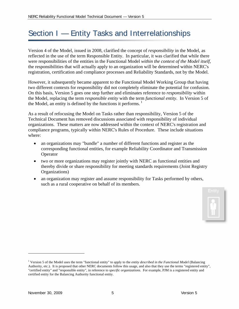
As a result of refocusing the Model on Tasks rather than responsibility, Version 5 of the Technical Document has removed discussions associated with responsibility of individual organizations. These matters are now addressed within the context of NERC's registration and compliance programs, typically within NERC's Rules of Procedure. These include situations where:
an organizations may "bundle" a number of different functions and register as the corresponding functional entities, for example Reliability Coordinator and Transmission Operator
two or more organizations may register jointly with NERC as functional entities and thereby divide or share responsibility for meeting standards requirements (Joint Registry Organizations)
an organization may register and assume responsibility for Tasks performed by others, such as a rural cooperative on behalf of its members.
1 Version 5 of the Model uses the term "functional entity" to apply to the entity described in the Functional Model (Balancing Authority, etc.). It is proposed that other NERC documents follow this usage, and also that they use the terms "registered entity", "certified entity" and "responsible entity", in reference to specific organizations. For example, PJM is a registered entity and certified entity for the Balancing Authority functional entity.
NERC Reliability Functional Model Technical Document — Version 5
November 30, 2009 6 Version 5
11.. RReelliiaabbiilliittyy CCoooorrddiinnaattoorr The Reliability Coordinator’s purview must be broad enough to enable it to calculate Interconnection Reliability Operating Limits, which will involve system and facility operating parameters beyond its own Area as well as within it. This is in contrast to the Transmission Operator, which also maintains reliability, but is directly concerned with system parameters within its own Area.
The Reliability Coordinator is the highest operating authority; the underlying premise is that reliability of a wide-area takes precedence over reliability of any single local area. Only the Reliability Coordinator has the perspective/vision necessary to act in the interest of wide-area reliability.
The Reliability Coordinator also assists the Transmission Operator in relieving equipment or facility overloads through transmission loading relief measures if market-based dispatch procedures are not effective.
Role in Interchange. The Reliability Coordinator does not receive tags, but may curtail Interchange Transactions until they are arranged and ready for implementation as Interchange Schedules. As such, it does not approve or deny tags. However, once the Reliability Coordinator receives the Interchange Schedule information, it will have the necessary information to aid its assessment of the impacts of flowing and impending Transaction Schedules on its area’s reliability. As necessary, the Reliability Coordinator may issue transmission loading relief requests (or similar requests for congestion management) which may result in reducing, removing or halting flowing or impending Interchange Transactions. This is viewed by some as “denying” the Interchange Transactions although in this context, the “denial” is not provided during the collection of approval stage.
Day-ahead analysis. The Reliability Coordinator will receive the dispatch plans from the Balancing Authority(ies) on a day-ahead basis. The Reliability Coordinator will then analyze the dispatch from a transmission reliability perspective. If the Reliability Coordinator determines that the Balancing Authority’s dispatch plans will jeopardize transmission reliability, the Reliability Coordinator will work with the Balancing Authority to determine where the dispatch plans need to be adjusted. The Reliability Coordinator obtains generation and transmission maintenance schedules from Generator Operators and Transmission Operators. The Reliability Coordinator can deny a transmission outage request if a transmission system reliability constraint would be violated.
The Transmission Operator is responsible for the reliability of its “local” transmission system in accordance with maintaining System Operating Limits (SOLs). However, in some circumstances, as noted above for reliability analysis associated with generation dispatch instructions, the Reliability Coordinator may become aware of a potential SOL violation and issue a dispatch adjustment. Therefore, in this context, the Reliability Coordinator also has a role regarding the Transmission Operator's management of SOLs.
NERC Reliability Functional Model Technical Document — Version 5
November 30, 2009 7 Version 5
Emergency actions. The Reliability Coordinator is responsible for Real-time system reliability, which includes calling for the following emergency actions:
Curtailing Interchange Schedules
Directing redispatch to alleviate congestion
Mitigating energy and transmission emergencies
Ensuring energy balance and Interconnection frequency
Directing load shedding.
The Reliability Coordinator, in collaboration with the Balancing Authority and Transmission Operator, can invoke public appeals, voltage reductions, demand-side management, and even load shedding if the Balancing Authority cannot achieve resource-demand balance.
System restoration actions. The Reliability Coordinator directs and coordinates system restoration with Transmission Operators and Balancing Authorities.
Authority to perform its reliability functions. The Reliability Coordinator’s authority is documented in one or more regional reliability plans, as applicable, for the Region in which the Reliability Coordinator Area is located. In cases where a Reliability Coordinator Area spreads over multiple Regions, its authority will be documented in and accepted by all the concerned Regions through their respective reliability plans.
In addition, since the Reliability Coordinator may also have a role regarding the Transmission Operator's management of SOLs, delineation of its authority and that of the Transmission Operator needs to be clearly defined in the reliability plan(s).
NERC Reliability Functional Model Technical Document — Version 5
November 30, 2009 8 Version 5
22.. BBaallaanncciinngg AAuutthhoorriittyy The Balancing Authority operates within the metered boundaries that establish the Balancing Authority Area. Every generator, transmission facility, and end-use customer is in a Balancing Authority Area. The Balancing Authority’s mission is to maintain the balance between loads and resources in real time within its Balancing Authority Area by keeping its actual interchange equal to its scheduled interchange and meeting its frequency bias obligation. The load-resource balance is measured by the Balancing Authority’s Area Control Error (ACE).
NERC’s Reliability Standards require that the Balancing Authority maintain its ACE within acceptable limits.
Maintaining resource-demand balance within the Balancing Authority Area requires four types of resource management, all of which are the Balancing Authority’s responsibility:
Frequency control through tie-line bias
Regulation service deployment
Load-following through economic dispatch
Interchange implementation
Frequency control through tie-line bias. To maintain frequency within acceptable limits, the Balancing Authority controls resources within its Balancing Authority Area to meet its frequency bias obligation to the interconnection.
Regulation service deployment. To maintain its ACE within these acceptable limits, the Balancing Authority controls a set of generators within its Balancing Authority Area that are capable of providing regulation service.
Load-following through economic dispatch. The organization that serves as the Balancing Authority will in general also perform unit commitment and economic dispatch; however, in some markets, Generator Operators may be permitted to perform unit commitment and economic dispatch among the fleet of generators under their control and within the requirements accepted by the market operator.
Interchange implementation. The Balancing Authority receives Confirmed Interchange from one or more Interchange Coordinators, and enters those Interchange Schedules into its energy management system.
Unit commitment and schedules from Load-Serving Entities. The Balancing Authority receives resource dispatch plans from the Market Operator and/or unit commitment and dispatch schedules from the Load-Serving Entities that have bilateral arrangements for generation within the market or the Balancing Authority Area. The Balancing Authority provides this commitment and dispatch schedule to the Reliability Coordinator.
Role in approving Interchange. The Balancing Authority approves an Arranged Interchange with respect to the ramping requirements of the generation that must increase or decrease to
NERC Reliability Functional Model Technical Document — Version 5
November 30, 2009 9 Version 5
implement the Interchange. The Balancing Authority provides its approval or denial to the Interchange Coordinator.
Energy Emergencies. In the event of an Energy Emergency, the Balancing Authority can implement public appeals, demand-side management programs, and, ultimately load shedding. Obviously, it must do this in concert with the Reliability Coordinator.
Failure to balance. The Balancing Authority must take action, either under its own initiative or direction by the Reliability Coordinator, if the Balancing Authority cannot comply with NERC’s Reliability Standards regarding frequency control and Area Control Error.
See “Managing Bilateral Interchange Transactions”
NERC Reliability Functional Model Technical Document — Version 5
November 30, 2009 10 Version 5
33.. PPllaannnniinngg CCoooorrddiinnaattoorr The Planning Coordinator coordinates and integrates transmission facility and service plans, resource plans, and protection system plans among the Transmission Planner(s) and Resource Planner(s) within its area of purview. These activities range from review and integration of reinforcement and corrective action plans developed by the functional entities whose area of responsibility is within the Planning Coordinator’s area with respect to established reliability needs to providing procedures, protocols, modeling and methodology software, etc. for consistent use within its area.
While much of what the Planning Coordinator performs could be actually performed by a Transmission Planner, such as developing methodologies in conjunction with surrounding Transmission Planners, recognition of resource plans, assessing system performance consistent with reliability needs by itself, and collaborating with other Transmission Planners to assess impacts on the interconnected area, the Planning Coordinator by its very nature will generally take responsibility over a wider perspective than the Transmission Planners for which its coordinates. The Planning Coordinator generally conducts system performance assessments, in collaboration with other Planning Coordinators to consider transfer/flows across multiple Transmission Planner areas or intra and interstate areas such as generation dispatch scenarios caused by temperature or fuel extremes. Geographic size is not necessarily a critical consideration, it is the extent and impact of the electrical network that the planners have taken responsibility for assessing that determines whether an area is large enough for analysis and planning
Although the Functional Model sets forth the concept of the Planning Coordinator and how a functional entity could perform as such, there may be situations or circumstances under actual organizational structures whereby a single entity does not exist that performs the Reliability Planning Function but rather the function is taken on by a number of entities, e.g. a group of Transmission Planners, or an organization such as a regional group formed within a region or possibly the Regional Entity itself. In all these cases the Reliability Planning Function is still performed in some manner by some entity or organization.
The boundaries for the Planning Coordinator area are basically defined by the location of the Bulk Electric System facilities under the purview of the Planning Coordinator, i.e. those facilities for which the Planning Coordinator coordinates and evaluates and recommends reinforcement and corrective plans resulting from studies and analysis of system performance and interconnection of facilities. The BES facilities under its purview, are generally contiguous and cover in aggregate the same areas as the Transmission Planners its coordinates. Traditionally transmission planning has been associated with one or more Transmission Owners, i.e. reinforcement and corrective action plans must be associated with certain Transmission Owner facilities. Since transmission ownership may cross state or provincial or regional boundaries, the BES facilities on one side of the Transmission Owner boundary may be in one Planning Coordinator area whereas the remaining facilities may be in another. As such the Planning Coordinator area is not constrained to fit within a Reliability Coordinator or Transmission Operator Area. However, the Planning Coordinator area must cover at least one Transmission
NERC Reliability Functional Model Technical Document — Version 5
November 30, 2009 11 Version 5
Planner Area and one Resource Planner area, or part thereof if either or both of these planner areas is larger than the Planning Coordinator area. On the other hand, there is the possibility that a Planning Coordinator area could be nested inside an even larger Planning Coordinator area provided the smaller Planning Coordinator does in fact perform the appropriate system assessments. In this special case, the larger Planning Coordinator would perform the ultimate planning coordinating function for all the Resource Planners, Transmission Planner and smaller Planning Coordinator in its Area. As an example, some ISOs and RTOs perform the Reliability Planning Functions but they are also under the purview of the Regional Entity that also performs the Reliability Planning Functions at a broader scale.
In many areas, there may exist more than one Transmission Planner and Resource Planner, as well as a nested Planning Coordinator, within a Planning Coordinator area, each performing a different role demarcated primarily by their particular function and scale (area-wise) of assessments performed. In these cases, delineation of the role of the various functional entities needs to be clearly defined in the regional reliability plan(s).
The Planning Coordinator is not responsible for implementing the transmission and resource plans. However, it helps to facilitate the process whereby adequate resources and transmission facilities are placed into service in a timely manner through the Resource Planners, Transmission Planners, and possibly others through the coordinated planning process.
NERC Reliability Functional Model Technical Document — Version 5
November 30, 2009 12 Version 5
44.. Transmission Planner The Transmission Planner develops a long-term (generally one year and beyond) plan for the reliability (adequacy) of the interconnected bulk electric transmission systems within its area of purview.
The boundaries for the Transmission Planner area are basically defined by the location of the Bulk Electric System facilities under the purview of the Transmission Planner, i.e. those facilities for which the Transmission Planner develops reinforcement and corrective action plans resulting from studies and analysis of system performance and interconnection of facilities. This means that the Transmission Planner’s area is not defined by the extent of the models it uses or studies that it performs since any planner can assess and perform simulations on readily available interconnection wide models. The BES facilities in its area, i.e. under its purview, are generally contiguous.
Traditionally transmission planning has been associated with one or more Transmission Owners, i.e. reinforcement and corrective action plans must be associated with the facilities of certain Transmission Owners. In some cases where transmission ownership crosses a state line, the BES facilities on one side of a geographic boundary line may be in one Transmission Planner Area while the remaining facilities may be in another. As such, the Transmission Planner Area is not constrained to fit within one Reliability Coordinator or Transmission Operator Area. However, the Transmission Planner Area can only be smaller than or equal to the area of its related Planning Coordinator.
Develop Transmission Expansion Plans. The Transmission Planner evaluates the facilities that will be needed in response to long-term requests for transmission service, and needed to integrate new generation, transmission, and end-use customers into the Bulk Electric Systems. In developing plans for transmission service and interconnection requests, the Transmission Planner is expected to coordinate plans or engage in joint planning with other Transmission Planners, as appropriate, to ensure new facilities do not adversely affect the reliability of neighboring transmission systems.
Based on customer requests for transmission service, native load growth, changes in existing native load, and the planning procedures and protocols established for their Transmission Planning Areas, the Transmission Planners will develop transmission plans to accommodate long-term firm transmission service requests and native load requirements with due regard to established reliability needs. While developing these plans, the Transmission Planner may provide alternate solutions and evaluate alternatives suggested by entities requesting customer service.
The Transmission Planners provide its transmission plans to its Planning Coordinator for review to ensure impacts on the interconnected systems are duly addressed. In reporting its transmission expansion plan to the Planning Coordinator, the Transmission Planner is expected to assess whether its plans for new or reinforced facilities meet reliability needs or whether corrective plans are necessary. The Transmission Planners work with the Planning Coordinator to identify
NERC Reliability Functional Model Technical Document — Version 5
November 30, 2009 13 Version 5
potential alternative solutions, including solutions proposed by stakeholders, to meet interconnected Bulk Electric System requirements.
NERC Reliability Functional Model Technical Document — Version 5
November 30, 2009 14 Version 5
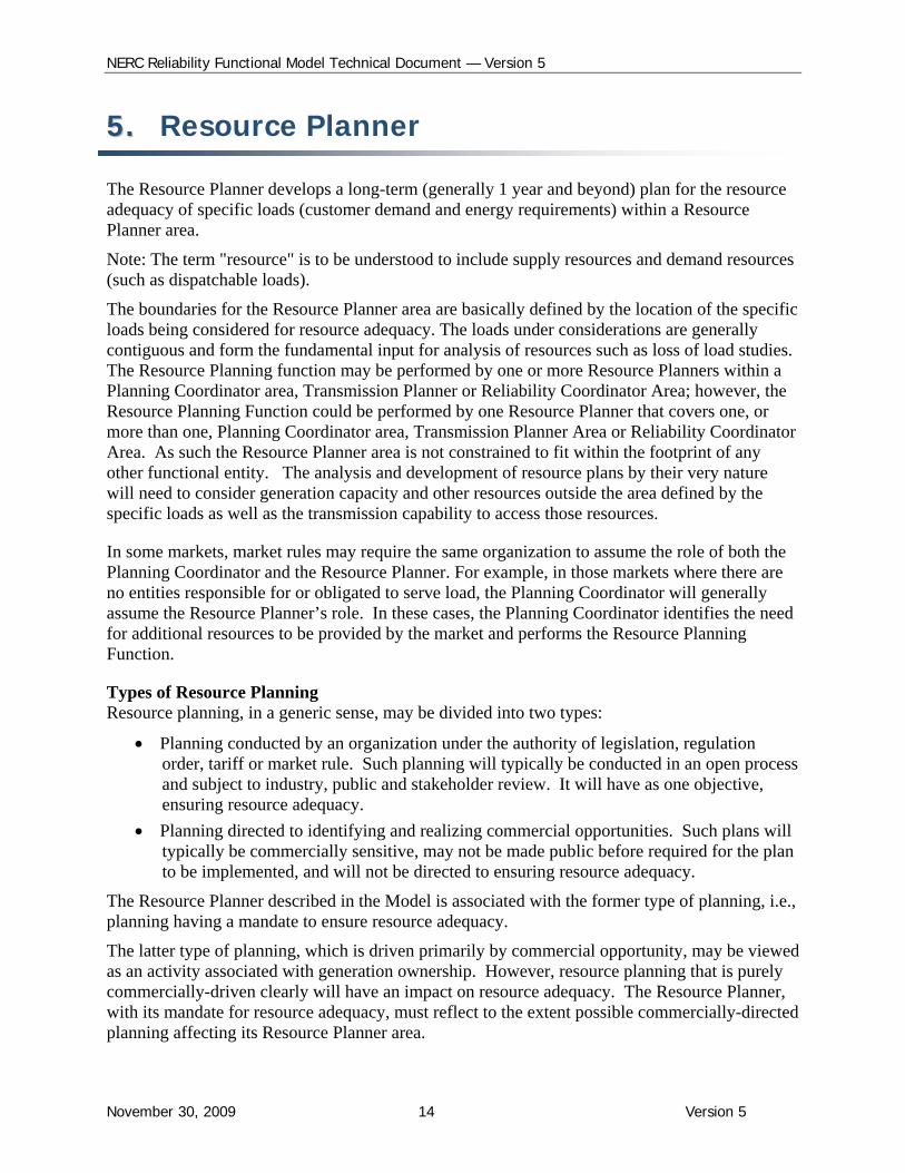
55.. Resource Planner The Resource Planner develops a long-term (generally 1 year and beyond) plan for the resource adequacy of specific loads (customer demand and energy requirements) within a Resource Planner area.
Note: The term "resource" is to be understood to include supply resources and demand resources (such as dispatchable loads).
The boundaries for the Resource Planner area are basically defined by the location of the specific loads being considered for resource adequacy. The loads under considerations are generally contiguous and form the fundamental input for analysis of resources such as loss of load studies. The Resource Planning function may be performed by one or more Resource Planners within a Planning Coordinator area, Transmission Planner or Reliability Coordinator Area; however, the Resource Planning Function could be performed by one Resource Planner that covers one, or more than one, Planning Coordinator area, Transmission Planner Area or Reliability Coordinator Area. As such the Resource Planner area is not constrained to fit within the footprint of any other functional entity. The analysis and development of resource plans by their very nature will need to consider generation capacity and other resources outside the area defined by the specific loads as well as the transmission capability to access those resources.
In some markets, market rules may require the same organization to assume the role of both the Planning Coordinator and the Resource Planner. For example, in those markets where there are no entities responsible for or obligated to serve load, the Planning Coordinator will generally assume the Resource Planner’s role. In these cases, the Planning Coordinator identifies the need for additional resources to be provided by the market and performs the Resource Planning Function.
Types of Resource Planning Resource planning, in a generic sense, may be divided into two types:
Planning conducted by an organization under the authority of legislation, regulation order, tariff or market rule. Such planning will typically be conducted in an open process and subject to industry, public and stakeholder review. It will have as one objective, ensuring resource adequacy.
Planning directed to identifying and realizing commercial opportunities. Such plans will typically be commercially sensitive, may not be made public before required for the plan to be implemented, and will not be directed to ensuring resource adequacy.
The Resource Planner described in the Model is associated with the former type of planning, i.e., planning having a mandate to ensure resource adequacy.
The latter type of planning, which is driven primarily by commercial opportunity, may be viewed as an activity associated with generation ownership. However, resource planning that is purely commercially-driven clearly will have an impact on resource adequacy. The Resource Planner, with its mandate for resource adequacy, must reflect to the extent possible commercially-directed planning affecting its Resource Planner area.
NERC Reliability Functional Model Technical Document — Version 5
November 30, 2009 15 Version 5
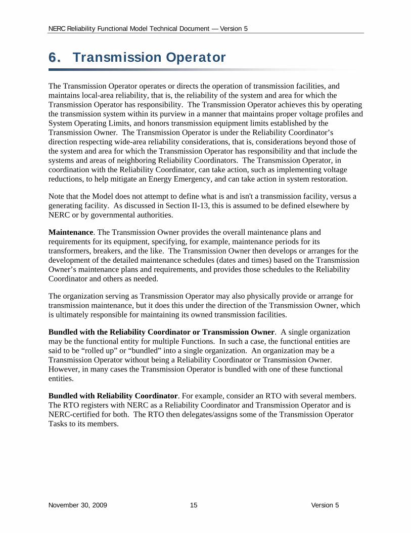
66.. Transmission Operator
The Transmission Operator operates or directs the operation of transmission facilities, and maintains local-area reliability, that is, the reliability of the system and area for which the Transmission Operator has responsibility. The Transmission Operator achieves this by operating the transmission system within its purview in a manner that maintains proper voltage profiles and System Operating Limits, and honors transmission equipment limits established by the Transmission Owner. The Transmission Operator is under the Reliability Coordinator’s direction respecting wide-area reliability considerations, that is, considerations beyond those of the system and area for which the Transmission Operator has responsibility and that include the systems and areas of neighboring Reliability Coordinators. The Transmission Operator, in coordination with the Reliability Coordinator, can take action, such as implementing voltage reductions, to help mitigate an Energy Emergency, and can take action in system restoration.
Note that the Model does not attempt to define what is and isn't a transmission facility, versus a generating facility. As discussed in Section II-13, this is assumed to be defined elsewhere by NERC or by governmental authorities.
Maintenance. The Transmission Owner provides the overall maintenance plans and requirements for its equipment, specifying, for example, maintenance periods for its transformers, breakers, and the like. The Transmission Owner then develops or arranges for the development of the detailed maintenance schedules (dates and times) based on the Transmission Owner’s maintenance plans and requirements, and provides those schedules to the Reliability Coordinator and others as needed.
The organization serving as Transmission Operator may also physically provide or arrange for transmission maintenance, but it does this under the direction of the Transmission Owner, which is ultimately responsible for maintaining its owned transmission facilities.
Bundled with the Reliability Coordinator or Transmission Owner. A single organization may be the functional entity for multiple Functions. In such a case, the functional entities are said to be “rolled up” or “bundled” into a single organization. An organization may be a Transmission Operator without being a Reliability Coordinator or Transmission Owner. However, in many cases the Transmission Operator is bundled with one of these functional entities.
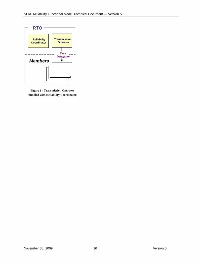
Bundled with Reliability Coordinator. For example, consider an RTO with several members. The RTO registers with NERC as a Reliability Coordinator and Transmission Operator and is NERC-certified for both. The RTO then delegates/assigns some of the Transmission Operator Tasks to its members.
NERC Reliability Functional Model Technical Document — Version 5
November 30, 2009 16 Version 5
TransmissionOperator
ReliabilityCoordinator
RTO
Members
TransmissionOwners
TransmissionOwners
TransmissionOwners
TaskDelegation
Figure 1 - Transmission Operator
bundled with Reliability Coordinator.
NERC Reliability Functional Model Technical Document — Version 5
November 30, 2009 17 Version 5
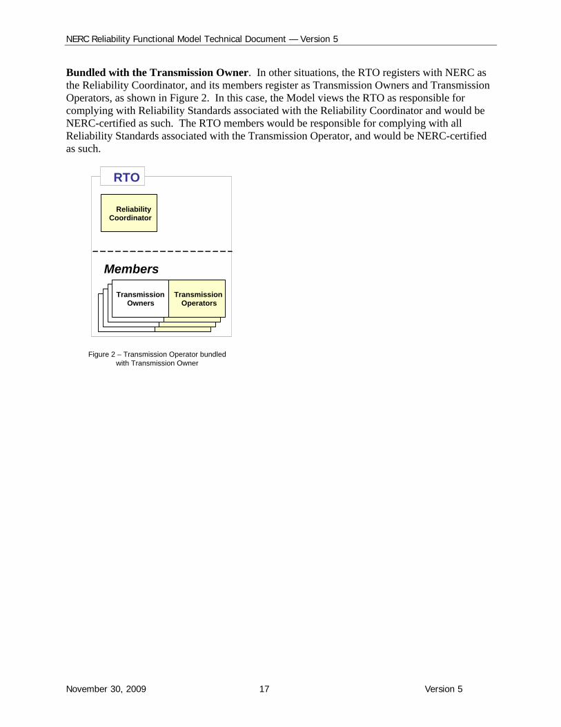
Bundled with the Transmission Owner. In other situations, the RTO registers with NERC as the Reliability Coordinator, and its members register as Transmission Owners and Transmission Operators, as shown in Figure 2. In this case, the Model views the RTO as responsible for complying with Reliability Standards associated with the Reliability Coordinator and would be NERC-certified as such. The RTO members would be responsible for complying with all Reliability Standards associated with the Transmission Operator, and would be NERC-certified as such.
TransmissionOperators
TransmissionOwners
TransmissionOwners
TransmissionOperators
TransmissionOperators
TransmissionOwners
TransmissionOwners
TransmissionOperators
ReliabilityCoordinator
RTO
Members
Figure 2 – Transmission Operator bundled with Transmission Owner
NERC Reliability Functional Model Technical Document — Version 5
November 30, 2009 18 Version 5
77.. Interchange Coordinator
The Interchange Coordinator collects approvals or denials for Arranged Interchange from Balancing Authorities and Transmission Service Providers and verifies the validity of the source and sink. The NERC Tag Authority provides this service that had been assigned to the Sink Balancing Authority.
The Interchange Coordinator provides the Balancing Authority with the individual bilateral Arranged Interchange. The Balancing Authority must track the individual Interchange Schedules in case one or more of them are curtailed by the Reliability Coordinator or by the Balancing Authority in those cases where a generator or load is interrupted. The Balancing Authority then creates a “net” interchange total for use in its energy management system as well as a “net” interchange for each neighboring Balancing Authority. The net Interchange Schedule for each neighboring Balancing Authority is used by the Receiving Balancing Authority for checkout with the neighboring Balancing Authorities.
All bilateral Interchange Transactions that cross a Balancing Authority Area boundary are coordinated through the Interchange Coordinator.
While the approval/denial process may utilize tools (such as computer software and communication protocols), the Model envisages that the Interchange function will be assigned to an actual organization. A Balancing Authority may serve as its own Interchange Coordinator or have this service provided by a separate organization.
Assessing ramping capability and connectivity. The Balancing Authority approves/denies the capability to ramp the Arranged Interchange in or out and notifies the Interchange Coordinator. The connectivity of adjacent Balancing Authorities is also verified by the Balancing Authorities before responding to the Interchange Coordinator.
Ensuring balanced, valid Interchange Transactions. The Interchange Coordinator also ensures that the resulting Confirmed Interchange Transactions is balanced and valid prior to physical delivery. This means:
The source MW must be equal to the sink MW (plus losses if they are “self-provided”), and
All reliability entities involved in the Arranged Interchange are currently in the NERC registry.
Only when it receives approvals from the Transmission Service Providers and Balancing Authorities, does the Interchange Coordinator direct the Balancing Authorities to implement the Transaction. If any of these entities — TSPs, or BAs — does not approve the Arranged Transaction, then the Interchange Coordinator does not authorize the Transaction to become Confirmed Interchange.
Curtailments. The Interchange Coordinator coordinates curtailments of Confirmed Interchange ordered by the Reliability Coordinator by notifying the Balancing Authorities, Transmission
NERC Reliability Functional Model Technical Document — Version 5
November 30, 2009 19 Version 5
Service Providers, and Purchasing-Selling Entities. The Interchange Coordinators also communicates and coordinates the resulting modified Arranged Interchange that result from the curtailments.
NERC Reliability Functional Model Technical Document — Version 5
November 30, 2009 20 Version 5
88.. Transmission Service Provider The Transmission Service Provider authorizes the use of the transmission system under its authority. In most cases, the organization serving as Transmission Service Provider is also the market operator.
Role in approving Interchange. The Transmission Service Provider approves Arranged Interchange by comparing the transmission service previously arranged by the transmission customer (Purchasing-Selling Entity, Generator Owner, Load-Serving Entity) with the transmission information supplied by the Interchange Coordinator. The Transmission Service Provider also ensures that there is a contiguous transmission path and that adjacent TSPs are on the scheduling path. The Transmission Service Provider then provides its approval or denial to the Interchange Coordinator.
Providing Transmission Service. As its name implies, the Transmission Service Provider provides transmission service to transmission customers, such as Generator Owners, Load-Serving Entities, and Purchasing-Selling Entities. The Transmission Service Provider determines Available Transfer Capability based on the established Total Transfer Capabilities, System Operating Limits and Interconnection Reliability Operating Limits (by various entities including the Planning Coordinator, Transmission Planner, Transmission Operator and Reliability Coordinator), and coordinates ATC with other Transmission Service Providers. The Transmission Service Provider manages the requests for transmission service according to the Transmission Owner’s tariff, and within the operating reliability limits determined by the Reliability Coordinator. The Transmission Service Provider does not itself have a role in maintaining system reliability in real time — that is done by the Reliability Coordinator and Transmission Operator.
The Transmission Service Provider arranges for transmission loss compensation with the Balancing Authority.
NERC Reliability Functional Model Technical Document — Version 5
November 30, 2009 21 Version 5
99.. Transmission Owner
The Transmission Owner owns its transmission facilities and provides for the maintenance of those facilities. It also specifies equipment operating limits, and supplies this information to the Transmission Operator, Reliability Coordinator, and Transmission Planner and Planning Coordinator.
In many cases, the Transmission Owner has contracts or interconnection agreements with generators or other transmission customers that would detail the terms of the interconnection between the owner and customer.
Relationship with the Transmission Operator. The organization serving as Transmission Owner may operate its transmission facilities or arrange for another organization (which may or may not be a Transmission Owner) to operate and/or maintain its transmission facilities.
See “Transmission Operator,” Section “Bundling with the Reliability Coordinator or Transmission Owner”
NERC Reliability Functional Model Technical Document — Version 5
November 30, 2009 22 Version 5
1100.. Distribution Provider The Distribution Provider provides the physical connection between the end-use customers and the electric system, including customers served at transmission level voltages. The Distribution Provider is not defined by a specific voltage, but rather as performing the Distribution function at any voltage. One Distribution Provider may be directly connected to another Distribution Provider and not directly connected to the Bulk Electric System.
The Distribution Provider maintains “local” safety and reliability. The Distribution Provider provides the switches and reclosers necessary for emergency action. The Distribution Provider may need to demonstrate load-shedding capability to the Balancing Authority and Transmission Operator.
The same organization may serve as the Distribution Provider and Load-Serving Entity, but they may be separate organizations as well. Unlike the Load-Serving Entity, the Distribution Provider has the facilities or assets (“wires”) and does not take title to any energy. However, while these functions are distinct, in many cases an organization, such as a vertically integrated utility, bundles these functions together.
NERC Reliability Functional Model Technical Document — Version 5
November 30, 2009 23 Version 5
1111.. Generator Operator
The Generator Owner may operate its generating facilities or designate a separate organization to perform the Generator Operation Function.
The Generator Operator operates, or directs the operation of generation facilities. The Generator Operator supports the needs of the Bulk Electric System up to the limits of the generating facilities in its purview. Ultimately the Generator Operator’s role is to meet generation schedules, manage fuel supplies, and provide frequency support and reactive resources without jeopardizing equipment.
Relationship with the Generator Owner. The organization that serves as Generator Operator may also be the owner of the generation facilities it operates; or it may be a separate organization designated by the Generator Owner to operate the facilities. The Generator Operator receives maintenance and performance verification schedules from the Generator Owner, and develops operating and unit commitment plans based on these schedules
Relationship with the Transmission Operator. The Generator Operator provides reliability-related services through arrangements or by direction from the Transmission Operator for support of the Bulk Electric System. The Generator Operator provides maintenance schedules, generator status, and AVR status to the Transmission Operator. The Generator Operator receives notification of transmission system problems affecting its generator from the Transmission Operator or Reliability Coordinator.
Relationship with the Balancing Authority. The Generator Operator provides unit commitment schedules, generator status, and operating and availability status of generating units to the Balancing Authority.
Relationship with the Reliability Coordinator. The Generator Operator provides annual maintenance plans, and operational data to the Reliability Coordinator. The Generator Operator takes actions based on directives from the Reliability Coordinator for the needs of the Bulk Electric System.
Relationship with Purchasing-Selling-Entity. The Generator Operator receives notice of Arranged Interchange approved by the Purchasing-Selling-Entity.
NERC Reliability Functional Model Technical Document — Version 5
November 30, 2009 24 Version 5
1122.. Generator Owner
The Generator Owner owns its generation facilities and provides for the maintenance of those facilities. It also provides verified equipment operating limits and supplies this information to the Generator Operator, Reliability Coordinator, Transmission Planner and Planning Coordinator.
In many cases, the Generator Owner has contracts or interconnection agreements with Transmission Owners or Distribution Providers that detail the terms of the interconnection between these parties.
Relationship with the Generator Operator. The organization serving as Generator Owner may operate generation facilities, or arrange for another organization to do so. In addition, the organization serving as Generator Owner may perform maintenance and facility verification, or may arrange with another organization to do so.
NERC Reliability Functional Model Technical Document — Version 5
November 30, 2009 25 Version 5
1133.. Purchasing-Selling Entity The Purchasing-Selling Entity (PSE) arranges for and takes title to energy products (capacity, energy and reliability-related services) that it secures from a resource for delivery to a Load-Serving Entity (LSE). The PSE also arranges for transmission service with the Transmission Service Provider that provides transmission service to the LSE under a tariff or market rule.
The Purchasing-Selling Entity initiates a bilateral Interchange between Balancing Authority Areas by submitting a Request for Interchange (RFI) to the Interchange Coordinator.
NERC Reliability Functional Model Technical Document — Version 5
November 30, 2009 26 Version 5
1144.. Load-Serving Entity
The Load-Serving Entity (LSE) arranges for the provision of energy to its end-use customers, but does not provide distribution services (“wires”). The LSE defined in the Model is not to be confused with or equated to the LSE as defined in any tariff or market rule.
Today, organizations serving as Load-Serving Entities may also be Generation Owners and can self-provide, or have contracts with other Generator Owners for capacity and energy to serve the LSE’s customers, or purchase capacity and energy from non-affiliated Generator Owners through a Purchasing-Selling Entity (or Market Operator), or employ a combination of these three options.
The Load-Serving Entity reports its generation (affiliated and non-affiliated) arrangements to serve load to the Balancing Authority, which forwards this information to the Reliability Coordinator, for day-ahead analysis.
The LSE may contract for reliability-related services through the Market Operator (if the LSE is part of a market or pool) or directly from Generator Owners or loads.
The same organization may serve as the Distribution Provider and Load-Serving Entity, but they may be separate organizations as well. Unlike the Distribution Provider, the Load-Serving Entity, does not have Bulk Electric System assets (“wires”) but does take title to energy. However, while these functions are distinct, in many cases an organization, such as a vertically integrated utility, bundles these functions together.
The Functional Model assigns to the LSE the identification of loads for curtailment and the development of load profiles and load forecasts. Please see Section II, 114: Roles in Load Curtailment for more detailed information.
The LSE communicates requests for voluntary curtailment to the appropriate end-use customer loads, thereby ensuring that these loads will in fact be curtailed.
NERC Reliability Functional Model Technical Document — Version 5
November 30, 2009 27 Version 5
1155.. Compliance Enforcement Authority
NERC is the Compliance Enforcement Authority. The Regional Entities have a major role in the actual performance of the monitoring, under delegated authority from NERC.
NERC Reliability Functional Model Technical Document — Version 5
November 30, 2009 28 Version 5
1166.. Standards Developer
The Standards Developer is written to be NERC. The Reliability Standards referenced in the Model consist of standards developed by either NERC or a Regional Entity and that are approved by NERC and subsequently by governmental authorities. This would therefore not include regional reliability criteria that are not submitted to NERC for approval. This is discussed further in Section II.
NERC Reliability Functional Model Technical Document — Version 5
November 30, 2009 29 Version 5
1177.. Market Operator (Resource Integrator)
Market Operations is not a reliability Function. It is included in the Model to provide a linkage between reliability Functions and commercial functions.
The associated functional entity is the Market Operator (Resource Integrator). The term Resource Integrator replaces Resource Dispatcher used in Version 3 of the Model. This recognizes that integration of resources is the essential feature, not resource dispatch, which is the responsibility of the Balancing Authority.
The Market Operator is described further in Section II, Technical Discussions.
NERC Reliability Functional Model Technical Document — Version 5
November 30, 2009 30 Version 5
1188.. Reliability Assurer
In Version 4 of the Model, the Reliability Assurer entity and the Reliability Assurance Function replaced Version 3’s Regional Reliability Organization entity and the Regional Reliability Assurance Function.
The change to Reliability Assurer reflected the fact that a name specific to the Model is preferable to a name already in use in another context. Moreover, since this Function can be performed on other than a regional basis, the Functional Model allows for the assignment to be made to an organization other than a Regional Entity.
The changes therefore provide NERC with flexibility in assigning the functional entity for Reliability Assurance.
The role of the Reliability Assurer may be considered to provide "defense-in-depth". That is, the Reliability Assurer provides an independent assessment of Tasks performed by other functional entities, or facilitates or coordinates such Tasks. While the specific role of the Reliability Assurer is not fully developed at the present time, the following are representative of the Tasks that might be performed:
Perform high level evaluations, such as at a regional or Interconnection level, of transmission and resource adequacy. These evaluations may be based on a review of the plans of Transmission Planners.
Develop regional reliability plans, to ensure there are no reliability gaps, or no missing or ambiguous responsibilities or relationships.
Perform high-level evaluations, such as at a regional or Interconnection level, of protection systems as they relate to the reliability of the Bulk Electric System.
Perform disturbance analysis evaluations.
The selection of particular Tasks for the Reliability Assurer will reflect NERC's judgment on which Tasks merit such a “defense-in-depth” approach.
NERC Reliability Functional Model Technical Document — Version 5
November 30, 2009 31 Version 5
SSeeccttiioonn IIII —— TTeecchhnniiccaall DDiissccuussssiioonnss
NERC Reliability Functional Model Technical Document — Version 5
November 30, 2009 32 Version 5
11.. General Clarifications of the Functional Model The general features of the Functional Model are described in the Introduction, Purpose and Guiding Principles sections of the Model. In brief:
The NERC Reliability Functional Model (“the Model”) provides the framework for the development and application of NERC’s Reliability Standards, as follows:
The Model describes a set of Functions that are performed to ensure the reliability of the Bulk Electric System. Each Function consists of a set of related reliability Tasks. The Model assigns each Function to a functional entity, that is, the entity that performs the Function's Tasks. The Model also describes the interrelationships between that functional entity and other functional entities (that perform other Functions).
NERC’s Standard Development Teams develop Reliability Standards that assign each reliability requirement within a standard to a functional entity, as defined in the Model.
This is possible because a given standard requirement will be logically related to a Task within a Function. A standards requirement will be very specific whereas a Task will be more general in nature.
NERC's compliance processes require specific organizations to register as functional entities and comply with standards requirements assigned to the functional entities.
The Model’s Functions and functional entities also provide for consistency and compatibility among different Reliability Standards.
The NERC Reliability Functional Model (“the Model”) does NOT address:
Entity Certification
Registration
Compliance
Sanctions
There are a number of clarifications that are important for those involved in developing standards and monitoring compliance with them. These clarifications are generally made in the Model itself, but because of their importance and potential for mis-interpretation, they warrant being repeated.
The Model is a guideline, it is not prescriptive. The Model is not a standard, and does not have compliance requirements. The Model is a guideline for the development of standards and their applicability; it is not a NERC requirement. Standards developers are not required to include tasks envisioned in the model, nor are the developers precluded from developing Reliability Standards that conflict with the Model. The Reliability Standards requirements take precedence over the Model.
A Functional Entity is not an actual organization. The Model describes Tasks performed by functional entities, which are in effect generic classes or categories of organizations — the
NERC Reliability Functional Model Technical Document — Version 5
November 30, 2009 33 Version 5
Model itself does not address specific organizations. The Model, for example, describes the Reliability Coordinator, a functional entity; the Model does not reference PJM and MISO, which are specific organizations. It is through NERC’s registration process that the PJM and MISO organizations become a member of the category of organization called Reliability Coordinator, and thereby responsible for meeting standards requirements specified for the Reliability Coordinator.
Reliability is best served if there is consistency of definitions within all NERC documents. These documents include, but are not limited to, the Functional Model, the NERC Rules of Procedure and Glossary of Terms.
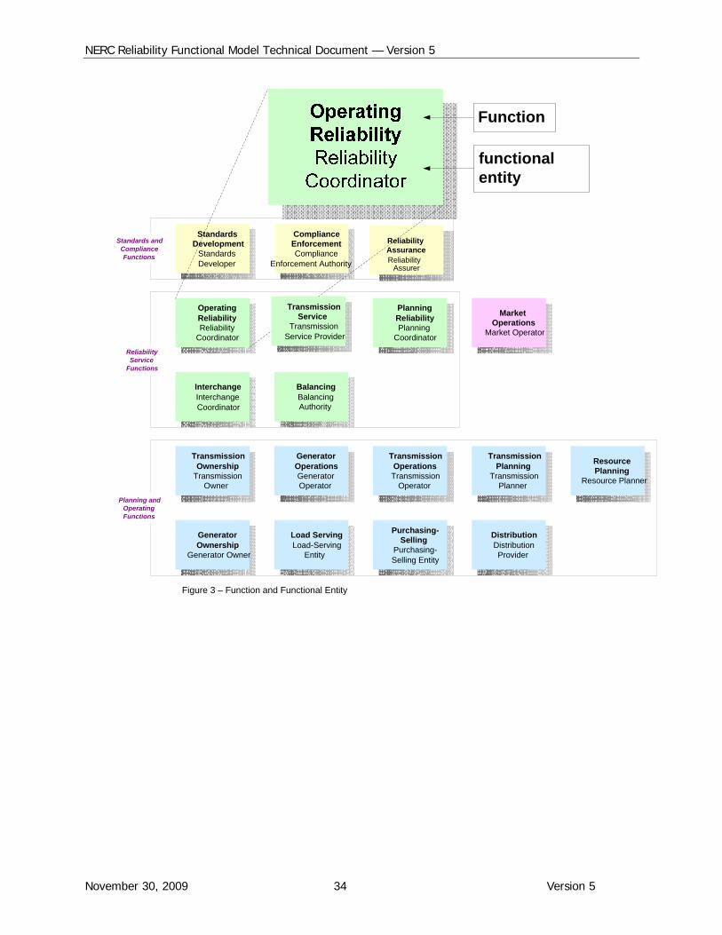
Every Function has an associated functional entity. A Function is a set of related reliability Tasks; whereas the functional entity is the name given to the category of organization that performs these Tasks. The diagram (Figure 3) of the Model includes two names within each Function box. The Function is shown in a larger typeface with the associated functional entity underneath.
NERC Reliability Functional Model Technical Document — Version 5
November 30, 2009 34 Version 5
StandardsDevelopment
StandardsDeveloper
ComplianceEnforcementCompliance
Enforcement Authority
OperatingReliabilityReliability
Coordinator
InterchangeInterchangeCoordinator
TransmissionOwnership
TransmissionOwner
GeneratorOwnership
Generator Owner
ReliabilityAssuranceReliability
Assurer
GeneratorOperationsGeneratorOperator
TransmissionOperationsTransmission
Operator
Load ServingLoad-Serving
Entity
Purchasing-Selling
Purchasing-Selling Entity
BalancingBalancingAuthority
PlanningReliabilityPlanning
Coordinator
TransmissionPlanning
TransmissionPlanner
DistributionDistributionProvider
ResourcePlanning
Resource Planner
Standards andComplianceFunctions
ReliabilityService
Functions
Planning andOperatingFunctions
Function
functional entity
Figure 3 – Function and Functional Entity
TransmissionService
TransmissionService Provider
MarketOperations
Market Operator
NERC Reliability Functional Model Technical Document — Version 5
November 30, 2009 35 Version 5
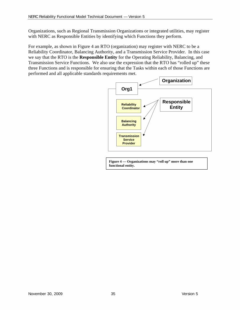
Organizations, such as Regional Transmission Organizations or integrated utilities, may register with NERC as Responsible Entities by identifying which Functions they perform.
For example, as shown in Figure 4 an RTO (organization) may register with NERC to be a Reliability Coordinator, Balancing Authority, and a Transmission Service Provider. In this case we say that the RTO is the Responsible Entity for the Operating Reliability, Balancing, and Transmission Service Functions. We also use the expression that the RTO has “rolled up” these three Functions and is responsible for ensuring that the Tasks within each of those Functions are performed and all applicable standards requirements met.
Org1
ReliabilityCoordinator
BalancingAuthority
TransmissionServiceProvider
Organization
ResponsibleEntity
Figure 4 — Organizations may “roll up” more than one functional entity.
NERC Reliability Functional Model Technical Document — Version 5
November 30, 2009 36 Version 5
22.. Reliability Standards The Functional Model describes the Standard Development Function and the Standards Developer functional entity and how these are related to Reliability Standards.
Reliability Standards can be developed at the North American level as well as at the regional level and can therefore be placed in two categories:
1. Reliability Standards Developed at the North American Level Within NERC NERC, under regulatory authority, develops and maintains Reliability Standards using the NERC Reliability Standards Development Procedures. The standards are applicable across North America upon approval by governmental authorities, unless specifically stated otherwise within the standard, and enable NERC and Regional Entities to monitor and enforce compliance with the standards requirements.
NERC can use the Reliability Standards Development Procedures to approve a variance from a NERC Reliability Standard; the variance then becomes part of the standard. The three categories of variance are:
Entity Variance that applies to an area less than a NERC Region
Regional Variance that applies to a NERC Region but less than an Interconnection
Regional Variance that applies to a NERC Region on an Interconnection-wide basis.
2. Reliability Standards Developed Within a Regional Entity Regional Entities may develop and propose to NERC regional reliability standards that:
Set more stringent reliability requirements than the NERC Reliability Standard
Cover matters not covered by an existing NERC Reliability Standard.
Alternatively, NERC may direct Regional Entities to develop a regional reliability standard in order to implement a NERC Reliability Standard. Such a regional reliability standard, upon approval by NERC, becomes part of the NERC Reliability Standard.
Regional Entities must use a NERC-approved development process to develop these regional reliability standards. Such regional reliability standards, upon approval by NERC, become NERC Reliability Standards. As appropriate, NERC will approve the regional reliability standard as an:
Interconnection-wide regional standard, or
Non-Interconnection-wide regional standard.
Regional Criteria. Regional Entities may develop regional reliability criteria that are necessary to implement, to augment or to comply with Reliability Standards, or to address issues not within the scope of Reliability Standards. Such criteria are not approved by NERC and are not (NERC)
NERC Reliability Functional Model Technical Document — Version 5
November 30, 2009 37 Version 5
Reliability Standards. As such, regional criteria, while clearly serving a reliability purpose, are best considered to be outside of the (NERC) Functional Model.
NERC Reliability Functional Model Technical Document — Version 5
November 30, 2009 38 Version 5
33.. Market Operations (Resource Integration) Market Operations is not a reliability Function. NERC does not assign standards requirements to the Market Operator.
Nevertheless, Market Operations, a commercial or market function, is included in the Functional Model, in order to provide an interface point between reliability and commercial functions.
The role of the Market Operator also varies in design and responsibilities, but all Market Operators perform a resource integration task of one form or another under a set of market rules that are recognized by a state, federal, or provincial regulator. Resource integration is discussed further in the following section II- 4, Functional Model and Market Structures.
Versions 4 and 5 of the Model refer to the entity as "Market Operator (Resource Integrator)", where Resource Integrator is seen as a better term than Market Operator in areas not having a full-service market. For simplicity, the discussion below uses only the term Market Operator, to apply even where there is not a full-service market.
1. The Market Operator in a Full-Service Market. A full-service market is one which offers both the commercial services such as integrating resources ahead of Real-time and settlement after the completion of Implemented Interchange and dispatch cycles, and implement the resource plan in Real-time, making adjustment as necessary to meet other reliability requirements not envisaged during the resource integration process (for example, reliability constraints). In a full service market, the Market Operator tasks involve integrating resources in accordance with established market rules. Following its market rules and using available market mechanisms, the Market Operator integrates market resources by establishing a generation dispatch plan to meet the load forecast for the upcoming dispatch cycle (typically five minutes or longer).
This generation dispatch plan is usually a function of the generators’ incremental bids (“merit order”). The established generation dispatch plan is submitted to the Balancing Authority for implementation. When the plan is tested for implementation, and limitations caused by transmission congestion are identified, the Balancing Authority will adjust the dispatch schedules accordingly. This constitutes a “security-constrained” dispatch.
Relationship between the Market Operator and Balancing Authority. In a full-service market, there is a close relationship between the Market Operator and the Balancing Authority. A full-service Market Operator performs resource integration tasks and is assigned the tasks of:
Determining the generation dispatch plan (unit commitment) ahead of time
Integrating scheduled interchange into that generation plan
Designating which generators are available for regulation service
Providing the generation dispatch plan to the Balancing Authority ahead of real time.
NERC Reliability Functional Model Technical Document — Version 5
November 30, 2009 39 Version 5
The Balancing Authority receives the plan, and implements it in real time.
2. The Market Operator Where There is not a Full-Service Market. In jurisdictions not having a full-service market there will often be a traditional, vertically-integrated utility that may be both the Market Operator and the Balancing Authority, and most or all of the associated tasks will be performed internal to the utility. The generation dispatch plan will typically be cost-based, in contrast to bid-based dispatch in a full-service market.
In addition, there are jurisdictions that use a model other than full-service market and vertically-integrated utility, in particular bilateral Interchange Transactions. In this case, the organization serving as Balancing Authority will also be the Market Operator, operating on the basis of net interchange.
NERC Reliability Functional Model Technical Document — Version 5
November 30, 2009 40 Version 5
44.. The Functional Model and Market Structures This section explains how the Functional Model can accommodate different market structures by examining these structures from the perspective of resource integration protocol.
Resource Integration Protocol. A resource integration protocol is the method used to determine the merit order of the generation to be dispatched. Generally, resource integration protocols are either cost-based or bid-based, depending on the market rules established by the regulatory authority, as described in section II-3, Market Operations (Resource Integration). The basis and the results for the resource integration algorithms are generally the same for cost-based and bid-based dispatch, which is why the Functional Model can accommodate either type of protocol.
Bid-Based Resource Integration. In those areas of the U.S. and Canada having a full-service market, market protocols provide Generator Owners the ability to bid into the market. In those cases, Generator Owners will direct the submission of bids via the Generator Operators to the Market Operator. The market protocols are established by the governmental authority, such as the Federal Energy Regulatory Commission in the U.S. and provincial regulators in Canada. The Market Operator, in turn, provides the Balancing Authority with the generator dispatch plan, so that the generators within the market footprint would be instructed to operate at the same incremental bid. Transmission constraints may cause the actual dispatch to deviate from the dispatch plan. Redispatch methods used to relieve the congestion may use: direct resource assignments, area / zonal dispatch signals, or bus-signals. The zonal and bus methodologies are often referred to as “Locational Marginal Pricing,” or LMP.
Cost-based Resource Integration. Where there is not a full-service market, the Market Operator may be a traditional, vertically-integrated utility that acts also as Balancing Authority. The utility will dispatch its resources based on its incremental costs (fuel and operations and maintenance) and losses. The regulatory authority, such as the state public utility commission, might specify the accounting rules for calculating these costs.
Multiple Balancing Authorities Within a Market Area. If the Market Area includes more than one Balancing Authority Area, then the Market Operator will also provide each Balancing Authority with the net “interchange” schedule that results from the resource plan (“Resource Dispatch Interchange Schedule”, or RDIS). Each Balancing Authority’s RDIS will be an import or export to the Balancing Area, and the sum of all RDISs within the Market Area must add to zero at each dispatch cycle.
NERC Reliability Functional Model Technical Document — Version 5
November 30, 2009 41 Version 5
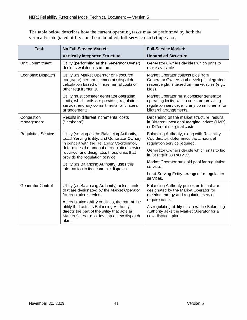
The table below describes how the current operating tasks may be performed by both the vertically-integrated utility and the unbundled, full-service market operator.
Task No Full-Service Market:
Vertically Integrated Structure
Full-Service Market:
Unbundled Structure
Unit Commitment Utility (performing as the Generator Owner) decides which units to run.
Generator Owners decides which units to make available.
Economic Dispatch Utility (as Market Operator or Resource Integrator) performs economic dispatch calculation based on incremental costs or other requirements.
Utility must consider generator operating limits, which units are providing regulation service, and any commitments for bilateral arrangements.
Market Operator collects bids from Generator Owners and develops integrated resource plans based on market rules (e.g., bids).
Market Operator must consider generator operating limits, which units are providing regulation service, and any commitments for bilateral arrangements.
Congestion Management
Results in different incremental costs (“lambdas”).
Depending on the market structure, results in Different locational marginal prices (LMP), or Different marginal costs
Regulation Service Utility (serving as the Balancing Authority, Load-Serving Entity, and Generator Owner) in concert with the Reliability Coordinator, determines the amount of regulation service required, and designates those units that provide the regulation service.
Utility (as Balancing Authority) uses this information in its economic dispatch.
Balancing Authority, along with Reliability Coordinator, determines the amount of regulation service required.
Generator Owners decide which units to bid in for regulation service.
Market Operator runs bid pool for regulation service.
Load-Serving Entity arranges for regulation services.
Generator Control Utility (as Balancing Authority) pulses units that are designated by the Market Operator for regulation service.
As regulating ability declines, the part of the utility that acts as Balancing Authority directs the part of the utility that acts as Market Operator to develop a new dispatch plan.
Balancing Authority pulses units that are designated by the Market Operator for meeting energy and regulation service requirements.
As regulating ability declines, the Balancing Authority asks the Market Operator for a new dispatch plan.
NERC Reliability Functional Model Technical Document — Version 5
November 30, 2009 42 Version 5
55.. Providing and Deploying Ancillary and Reliability-Related Services
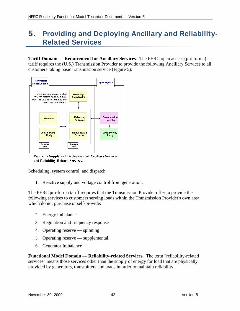
Tariff Domain — Requirement for Ancillary Services. The FERC open access (pro forma) tariff requires the (U.S.) Transmission Provider to provide the following Ancillary Services to all customers taking basic transmission service (Figure 5):
Scheduling, system control, and dispatch
1. Reactive supply and voltage control from generation.
The FERC pro-forma tariff requires that the Transmission Provider offer to provide the following services to customers serving loads within the Transmission Provider's own area which do not purchase or self-provide:
2. Energy imbalance
3. Regulation and frequency response
4. Operating reserve — spinning
5. Operating reserve — supplemental.
6. Generator Imbalance
Functional Model Domain — Reliability-related Services. The term "reliability-related services" means those services other than the supply of energy for load that are physically provided by generators, transmitters and loads in order to maintain reliability.
NERC Reliability Functional Model Technical Document — Version 5
November 30, 2009 43 Version 5
Reliability-related services include voltage control and reactive power resources from generators, transmitters and loads. Certain transmission facilities can provide reactive support, but are not considered an Ancillary Service in the open access tariff, rather, they are considered part of basic transmission service. In addition, loads may provide reserves through load-shedding or demand-side management, and may also provide frequency response.
Figure 5 shows how Ancillary Services in the “tariff domain” could be served by reliability-related services in the "reliability domain". The Functional Model explains that the Balancing Authority, alone or in coordination with the Reliability Coordinator, determines the amount required and arranges for reliability-related services to ensure balance:
The Balancing Authority determines regulation, load following, frequency response, and contingency reserves, etc., and deploys these as reliability-related services.
The Transmission Operator determines the reliability-related services necessary to meet its reactive power requirements to maintain transmission voltage within operating limits, and deploys these as its set of reliability-related services.
The Reliability Coordinator, working with the Transmission Operator, determines the need for Black Start capacity. The Transmission Operator cannot do this alone, because it may not have a wide enough picture of the transmission system.
Through its Reliability Standards, NERC holds organizations (those registered as Reliability Coordinators, Balancing Authorities, Transmission Operators and Transmission Service Providers) responsible to comply with applicable standards requirements, including those requirements that depend on reliability-related services. The quantity of and processes used to deploy those reliability-related services depend on the Regional and local system characteristics and regulatory requirements. The responsible organizations establish the quality and quantity of their own reliability-related services, using these processes and procedures in a manner that ensures compliance with the standards’ requirements.
NERC Reliability Functional Model Technical Document — Version 5
November 30, 2009 44 Version 5
66.. Managing Bilateral Interchange Transactions — Basic Concepts
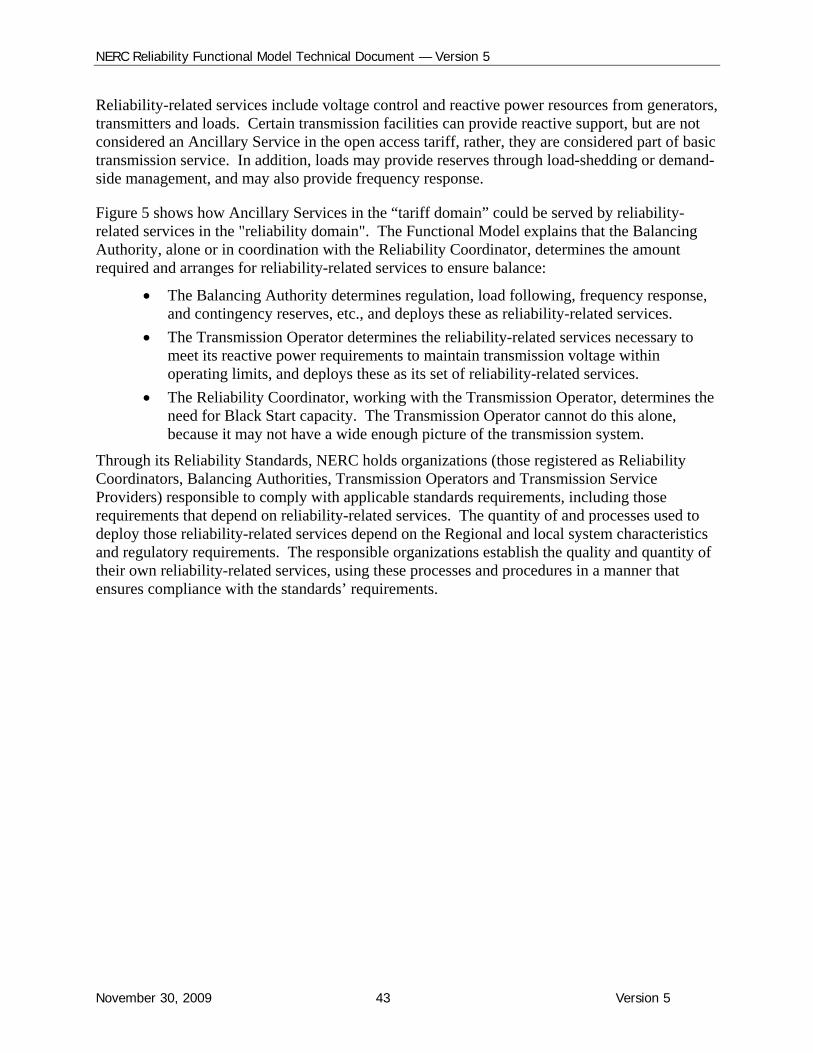
Interchange that crosses multiple Balancing Authority (BA) Areas can be broken down daisy-chain fashion into individual Balancing Authority-to-Balancing Authority Interchange Transactions, with the Sink Balancing Authority designated as the “manager” (the “Tag Authority”).
The Functional Model recognizes this Interchange process as the current Industry practice and includes BA-to-BA “after hour” checkout for net Interchange between adjacent Balancing Authorities. Also, the Interchange Coordinator function “coordinates” and “communicates Interchange (“deals”) that is ready for physical implementation between Balancing Authorities. The IC receives approvals that recognize ramping capability. The IC also communicates the individual Interchange information to all involved parties (Figure 6).
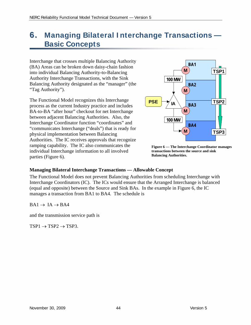
Managing Bilateral Interchange Transactions — Allowable Concept
The Functional Model does not prevent Balancing Authorities from scheduling Interchange with Interchange Coordinators (IC). The ICs would ensure that the Arranged Interchange is balanced (equal and opposite) between the Source and Sink BAs. In the example in Figure 6, the IC manages a transaction from BA1 to BA4. The schedule is
BA1 IA BA4
and the transmission service path is
TSP1 TSP2 TSP3.
BA1
BA2
BA3
M
M
M
BA4M
TSP1
TSP2
TSP3
IA
100 MW
100 MW
PSE
Figure 6 — The Interchange Coordinator manages transactions between the source and sink Balancing Authorities.
NERC Reliability Functional Model Technical Document — Version 5
November 30, 2009 45 Version 5
Interchange Transactions within a Balancing Authority Area. A bilateral Interchange within a Balancing Authority Area does not require Interchange Coordinator authorization. In the example in Figures 8 and 9, the Purchasing-Selling Entity submits the 100 MW request for Interchange to the Balancing Authority who will inform the Resource Integrator (or Market Operator) if the Resource Integrator needs to know which generators are committed to the Interchange, and to the Reliability Coordinator for reliability assessment.
The tables on the following page compare the Interchange checkout procedures that the Balancing Authorities use today with the procedures that the Balancing Authorities would use if this type of Interchange concept were applied.
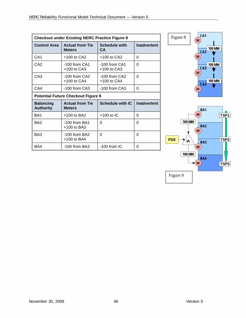
NERC Reliability Functional Model Technical Document — Version 5
November 30, 2009 46 Version 5
Checkout under Existing NERC Practice Figure 8
Control Area Actual from Tie Meters
Schedule with CA
Inadvertent
CA1 +100 to CA2 +100 to CA2 0
CA2 -100 from CA1 +100 to CA3
-100 from CA1 +100 to CA3
0
CA3 -100 from CA2 +100 to CA4
-100 from CA2 +100 to CA4
0
CA4 -100 from CA3 -100 from CA3 0
Potential Future Checkout Figure 9
Balancing Authority
Actual from Tie Meters
Schedule with IC Inadvertent
BA1 +100 to BA2 +100 to IC 0
BA2 -100 from BA1 +100 to BA3
0 0
BA3 -100 from BA2 +100 to BA4
0 0
BA4 -100 from BA3 -100 from IC 0
BA1
BA2
BA3
M
M
M
BA4M
TSP1
TSP2
TSP3
IA
100 MW
100 MW
PSE
CA1
CA2
CA3
M
M
M
CA4M
100 MW
100 MW
100 MW
CA1
CA2
CA3
M
M
M
CA4M
100 MW
100 MW
100 MW
Figure 8
Figure 9
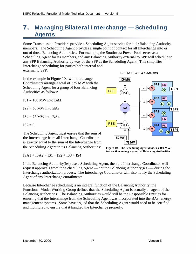
NERC Reliability Functional Model Technical Document — Version 5
November 30, 2009 47 Version 5
77.. Managing Bilateral Interchange — Scheduling Agents
Some Transmission Providers provide a Scheduling Agent service for their Balancing Authority members. The Scheduling Agent provides a single point of contact for all Interchange into or out of those Balancing Authorities. For example, the Southwest Power Pool serves as a Scheduling Agent for its members, and any Balancing Authority external to SPP will schedule to any SPP Balancing Authority by way of the SPP as the Scheduling Agent. This simplifies Interchange scheduling for parties both internal and external to SPP.
In the example in Figure 10, two Interchange Coordinators arrange a total of 225 MW with the Scheduling Agent for a group of four Balancing Authorities as follows:
IS1 = 100 MW into BA1
IS3 = 50 MW into BA3
IS4 = 75 MW into BA4
IS2 = 0
The Scheduling Agent must ensure that the sum of the Interchange from all Interchange Coordinators is exactly equal to the sum of the Interchange from the Scheduling Agent to its Balancing Authorities:
ISA1 + ISA2 = IS1 + IS2 + IS3 + IS4
If the Balancing Authority(ies) use a Scheduling Agent, then the Interchange Coordinator will request approvals from the Scheduling Agent — not the Balancing Authority(ies) — during the Interchange authorization process. The Interchange Coordinator will also notify the Scheduling Agent of any Interchange curtailments.
Because Interchange scheduling is an integral function of the Balancing Authority, the Functional Model Working Group defines that the Scheduling Agent is actually an agent of the Balancing Authorities. The Balancing Authorities would still be the Responsible Entities for ensuring that the Interchange from the Scheduling Agent was incorporated into the BAs’ energy management systems. Some have argued that the Scheduling Agent would need to be certified and monitored to ensure that it handled the Interchange properly.
BA1
BA2
BA3
GM
M
M
BA4M
G
G G
GG
TSP1
TSP2
TSP3
RD
RD
RD
RD
IA1
SA
100 MW
Is1
Is2
Is3
Is4
Is1 + Is2 + Is3 + Is4 = 225 MW
IA2
50 MW
75 MW
PSE
PSE
Figure 10 - The Scheduling Agent divides a 100 MW transaction among a group of Balancing Authorities.
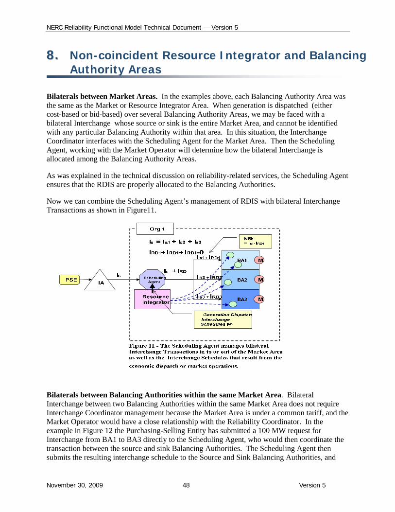
NERC Reliability Functional Model Technical Document — Version 5
November 30, 2009 48 Version 5
88.. Non-coincident Resource Integrator and Balancing Authority Areas
Bilaterals between Market Areas. In the examples above, each Balancing Authority Area was the same as the Market or Resource Integrator Area. When generation is dispatched (either cost-based or bid-based) over several Balancing Authority Areas, we may be faced with a bilateral Interchange whose source or sink is the entire Market Area, and cannot be identified with any particular Balancing Authority within that area. In this situation, the Interchange Coordinator interfaces with the Scheduling Agent for the Market Area. Then the Scheduling Agent, working with the Market Operator will determine how the bilateral Interchange is allocated among the Balancing Authority Areas.
As was explained in the technical discussion on reliability-related services, the Scheduling Agent ensures that the RDIS are properly allocated to the Balancing Authorities.
Now we can combine the Scheduling Agent’s management of RDIS with bilateral Interchange Transactions as shown in Figure11.
Bilaterals between Balancing Authorities within the same Market Area. Bilateral Interchange between two Balancing Authorities within the same Market Area does not require Interchange Coordinator management because the Market Area is under a common tariff, and the Market Operator would have a close relationship with the Reliability Coordinator. In the example in Figure 12 the Purchasing-Selling Entity has submitted a 100 MW request for Interchange from BA1 to BA3 directly to the Scheduling Agent, who would then coordinate the transaction between the source and sink Balancing Authorities. The Scheduling Agent then submits the resulting interchange schedule to the Source and Sink Balancing Authorities, and
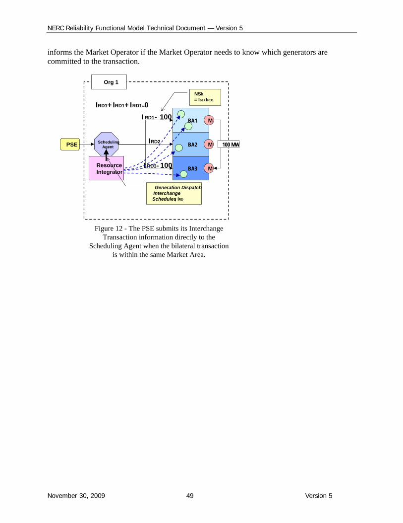
NERC Reliability Functional Model Technical Document — Version 5
November 30, 2009 49 Version 5
informs the Market Operator if the Market Operator needs to know which generators are committed to the transaction.
BA1
BA2
BA3
SchedulingAgent
IRD2
I RD3+ 100
I RD1 - 100
ResourceIntegrator
Generation Dispatch Interchange Schedules, IRD
IRD1+ IRD1+ IRD1=0NSI1= Is1+ IRD1
M
M
M
Org 1
100 MWPSE
Figure 12 - The PSE submits its Interchange Transaction information directly to the
Scheduling Agent when the bilateral transaction is within the same Market Area.
NERC Reliability Functional Model Technical Document — Version 5
November 30, 2009 50 Version 5
99.. Implementing the Interchange Coordinator
The IC Tasks are being performed by the organization registered as BAs, specifically the "sink BA"2 for a particular interchange transaction. It has been noted that the Functional Model could in principle have assigned the IC Tasks to the BA and avoided the need for a separate Interchange function. This approach was not followed because it was envisioned in the future that the IC Tasks could be performed by entities other than a BA, a possibility that is allowed for by defining the IC separate from the BA. Therefore, the Functional Model accommodates the sink BA as the IC, but does not require it.
The implementation of the IC extends also to the NERC INT standards that exist today, which impose data collecting and interchange-information distribution requirements on an IC.
The NERC direction regarding registering of ICs is compatible with the approach taken in the Model:
There is a need for a separate Interchange Coordinator functional entity
Allowance is made for BAs to register as ICs, but organizations that are not BAs are not precluded from doing so.
The IC is an entity, not a software tool.
The remainder of this section clarifies the context and need for an IC from the perspective of the Model, by describing the associated reliability tasks and their implications. As such, it may be of use to those involved in registration processes.
INTERCHANGE PRACTICE
Background To help ensure reliability, “requests” for interchange transactions (Arranged Interchange) must be approved before that request is allowed to become an “implemented” interchange transaction (Confirmed Interchange). Without approvals, it is possible that the sum of all interchange schedules in an interconnection will not sum to zero. That, in turn, would lead to the condition that even if every BA were controlling to zero Area Control Error, there could still be off-generation occurring because of the Net schedule being in error.
Historically, approvals were handled on a control area to control area basis. Net interchange schedules between neighbors were checked and approved prior to implementation. Only if there were disagreements did individual requests get checked. This pragmatic practice served the industry well — but not perfectly. When given control areas did not take the time to compute their own Net Schedule interchange (and instead merely accepted the numbers from its individual neighbors) — what can and did happen was that individual schedules were active on one side of the control area, but not on the other side. Not until serious operational symptoms
2 That is, the BA in whose area the bilateral interchange transaction terminates.
NERC Reliability Functional Model Technical Document — Version 5
November 30, 2009 51 Version 5
arose (e.g., unexplained parallel flows, or unusual number of time error corrections) was there an investigation.
Current Practice The Functional Model’s inclusion of an IC recognizes a reliability concern regarding responsibility for approving a request for interchange, and the distribution of the information for the approved request for interchange. Each and every transaction that a PSE desires to implement must have approvals from all parties involved, and must have approval by each of them regarding the characteristics of each of those transactions.
Today, the approval and communication are implemented in a two-step process — each step focusing on different quantities. One step focuses on the individual transactions and their respective characteristics. This step is carried out by a tagging authority. The other step focuses on implementing Net schedules (i.e., the net of the transactions that were approved). This step is carried out by neighboring BAs. This two-step process can and does work. The problem is that when there is a breakdown in the process, there is no compliance process in place.
For example, if the tagging authority were the root cause of non-compliance (such as a computer error) that caused transaction information to elude analysis of a participant in the transaction, and that error resulted in a blackout, then no one would be held non-compliant, if no entity is registered as IC for the transaction. If a BAleft accepts a Net Schedule from BAcenter but the transactions within that Net do not agree with the complementary transactions of the accepted Net Schedule between BAcenter and BAright, then again no one can be held non-compliant if no one is registered as IC.
What is in place today is the NERC Tagging Specification, under which each sink BA is responsible for providing Tagging Services, either directly or by arranging with a third party to provide this service as its agent.3 However, the Tagging Specification is not a standard and therefore not a sufficient basis for compliance enforcement.
An important question for many within industry is “how do you implement the concept of an Interchange Coordinator (IC)”.
The initial step of the implementation requirements has been met with the NERC Board adoption of the Version 1 Interchange standards, which contain concepts and functions of the IA (now referred to as the IC). The Electronic Tagging Function Specification assigns the Tag Authority requirements to the entity responsible for Balancing Authority operations (i.e., Sink BA).
To implement this concept, the Electronic Tagging Functional Specification (E-tag Spec.) was revised to map the Tagging Service requirement from the Balancing Authority to the entity performing the Interchange function for the Sink Balancing Authority’s organization (still allows the Sink BA to use third party to fulfill the tasks of the requirements).
3Electronic Tagging Functional Specification, ver 1.8.0, approved Nov 7, 2007, http://reg.tsin.com/Tagging/e-tag/e-tag-spec-v-18-20071107.doc )
NERC Reliability Functional Model Technical Document — Version 5
November 30, 2009 52 Version 5
1100.. Distribution Provider as Load-Serving Entity FERC Order of October 16, 20084 approved a NERC filing that proposed, as a short-term solution, revisions to the NERC Statement of Compliance Registry Criteria (Registry Criteria) to provide that a distribution provider to whose system the electric loads in retail choice areas are connected will be registered as the LSE for all loads connected to its system.
The Order requires that “the Distribution Provider to whose system the electric loads in retail choice areas are connected are to be registered as the LSE for all loads connected to its system for the purpose of compliance with NERC’s approved reliability standards applicable to LSEs.”
NERC states that, with respect to load served by retail choice through load aggregators, there may not be a clear agreement in place between the distribution providers and the load aggregators delineating the responsibilities between the parties regarding compliance with mandatory Reliability Standards. Further, the compliance filing explains that “NERC will exercise its discretion in the application of penalties or sanctions upon Distribution Providers who are providing this information on the behalf of loads served by a retail choice load aggregator until such time as both entities are either registered or the standards are updated to clarify the responsibilities for each party as ultimately indentified in the longer-term solution proposed by NERC.”
NERC stated that DPs have both the infrastructure and access to information to enable them to comply with the Reliability Standards that apply to LSEs. Moreover, distribution providers provide the wires over which the load of retail power marketers is served. NERC also pointed out that, with regard to distribution providers that provide wires service for retail power marketers, these DPs were LSEs for that load prior to state retail access programs. In many instances, these distribution providers remain providers of last resort and must plan their system taking into consideration all load served over their wires, including retail access load.
The Order also provides that a distribution provider will not be registered based on the above criterion if it has transferred responsibility to another entity (that is appropriately registered) by written agreement.
NERC also stated that this approach ensures that all loads are represented in the planning and operation of the Bulk-Power System by the entity with the best information regarding those loads.
The scope of the review leading to Version 5 of the Functional Model included consideration of whether changes should be made in the Model to accommodate these changes to the Registry Criteria.
Version 5 does not contain changes to reflect these changes to the Registry Criteria, as follows:
4 This section contains extracts from the order, which may be found at http://www.nerc.com/files/Statement_Compliance_Registry_Criteria-V5-0.pdf
NERC Reliability Functional Model Technical Document — Version 5
November 30, 2009 53 Version 5
the problem and its solution relate to registration, not the Tasks performed, and as such do not directly affect the Model; this is in keeping with the approach used for the Joint Registration Organization, which is defined for compliance purposes and not in the Model
the present solution is a short-term one, with the longer-term solution yet to be defined.

NERC Reliability Functional Model Technical Document — Version 5
November 30, 2009 54 Version 5
1111.. Terminology Changes in Version 5 Version 5 contains terminology changes intended to improve consistency between the Model and the NERC Glossary, the Rules of Procedure (ROP) and Reliability Standards.5 Inconsistency has potential for creating needless complexity, confusion and wasted effort for those who use NERC documents. The changes are of three types:
Entity terminology
Entity names
Entity definitions.
Entity terminology
The term “responsible entity” in the Model has been changed to “functional entity”. 6
o The usage of “responsible” in Version 4 derived from an earlier version of the Model. Version 4 clarified that the Model is limited to describing the performance of tasks, but not compliance aspects such as responsibility for such performance. Version 5 takes this clarification one step further by replacing the term “responsible” in the Model.
o The Model uses the term functional entity to apply to a class of entity, such as a Balancing Authority, and makes no reference to the specific organizations that register as functional entities. Consistency within NERC documents would be improved if conforming changes were made to the NERC Rules of Procedure and Glossary of Terms to consistently use the term “functional entity” when the reference is to the class of entity (e.g., BA), and use the terms “responsible entity” and “registered entity” when the reference is to a specific organization regarding its responsibility or registration, respectively.7
Entity names
The functional entity name Interchange Authority has been changed to Interchange Coordinator
o The term “coordinator” better reflects the nature of the function.
o A conforming change would be required in the Glossary (which also uses Interchange Authority)
Conforming changes would be required in other NERC documents. Entity definitions
5 Full alignment will require conforming changes in Reliability Standards, the Glossary and ROP. These changes are seen as editorial that is, not representing changes to essential content. 6 Version 4 actually uses “Responsible Entity”. Because the Glossary and ROP generally use “responsible entity”, i.e., all lower case, this usage has been adopted for version 5 of the Model. 7 These changes in terminology are intended to address confusion between the entity described in the Model and specific organizations, which has been a frequently expressed concern of stakeholders.
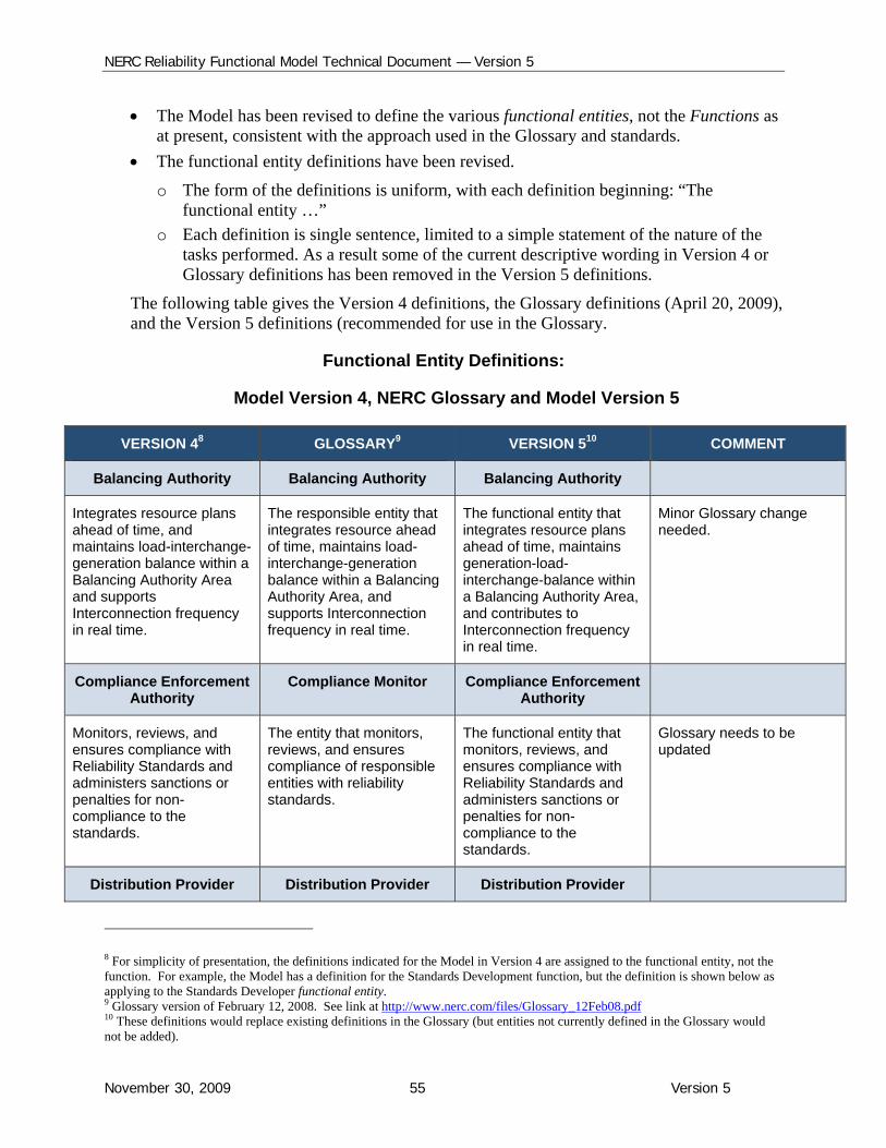
NERC Reliability Functional Model Technical Document — Version 5
November 30, 2009 55 Version 5
The Model has been revised to define the various functional entities, not the Functions as at present, consistent with the approach used in the Glossary and standards.
The functional entity definitions have been revised.
o The form of the definitions is uniform, with each definition beginning: “The functional entity …”
o Each definition is single sentence, limited to a simple statement of the nature of the tasks performed. As a result some of the current descriptive wording in Version 4 or Glossary definitions has been removed in the Version 5 definitions.
The following table gives the Version 4 definitions, the Glossary definitions (April 20, 2009), and the Version 5 definitions (recommended for use in the Glossary.
Functional Entity Definitions:
Model Version 4, NERC Glossary and Model Version 5
VERSION 48 GLOSSARY9 VERSION 510 COMMENT
Balancing Authority Balancing Authority Balancing Authority
Integrates resource plans ahead of time, and maintains load-interchange-generation balance within a Balancing Authority Area and supports Interconnection frequency in real time.
The responsible entity that integrates resource ahead of time, maintains load-interchange-generation balance within a Balancing Authority Area, and supports Interconnection frequency in real time.
The functional entity that integrates resource plans ahead of time, maintains generation-load-interchange-balance within a Balancing Authority Area, and contributes to Interconnection frequency in real time.
Minor Glossary change needed.
Compliance Enforcement Authority
Compliance Monitor Compliance Enforcement Authority
Monitors, reviews, and ensures compliance with Reliability Standards and administers sanctions or penalties for non-compliance to the standards.
The entity that monitors, reviews, and ensures compliance of responsible entities with reliability standards.
The functional entity that monitors, reviews, and ensures compliance with Reliability Standards and administers sanctions or penalties for non-compliance to the standards.
Glossary needs to be updated
Distribution Provider Distribution Provider Distribution Provider
8 For simplicity of presentation, the definitions indicated for the Model in Version 4 are assigned to the functional entity, not the function. For example, the Model has a definition for the Standards Development function, but the definition is shown below as applying to the Standards Developer functional entity. 9 Glossary version of February 12, 2008. See link at http://www.nerc.com/files/Glossary_12Feb08.pdf 10 These definitions would replace existing definitions in the Glossary (but entities not currently defined in the Glossary would not be added).

NERC Reliability Functional Model Technical Document — Version 5
November 30, 2009 56 Version 5
VERSION 48 GLOSSARY9 VERSION 510 COMMENT
Provides facilities that interconnect an End-use Customer load and the electric system for the transfer of electrical energy to the End-use Customer.
Provides and operates the “wires” between the transmission system and the end-use customer. For those end-use customers who are served at transmission voltages, the Transmission Owner also serves as the Distribution Provider. Thus, the Distribution Provider is not defined by a specific voltage, but rather as performing the Distribution function at any voltage.
The functional entity that provides facilities that interconnect an End-use Customer load and the electric system for the transfer of electrical energy to the End-use Customer.
Glossary change needed – descriptive detail removed. Revised version would be essentially that of Version 4 of the Model.
Generator Operator Generator Operator Generator Operator
Operates generating unit(s) to provide real and reactive power.
The entity that operates generating unit(s) and performs the functions of supplying energy and Interconnected Operations Services.
The functional entity that operates generating unit(s) and performs the functions of supplying energy and reliability-related services.
Minor Glossary change needed.
Generator Owner Generator Owner Generator Owner
Owns and provides for maintenance of generating facilities.
Entity that owns and maintains generating units.
The functional entity that owns and maintains generating units.
Minor Glossary change needed.
Interchange Coordinator Interchange Authority Interchange Coordinator
Ensures communication of Arranged Interchange for reliability evaluation purposes and coordinates implementation of valid and balanced Arranged Interchange between Balancing Authority Areas.
The responsible entity that authorizes implementation of valid and balanced Interchange Schedules between Balancing Authority Areas, and ensures communication of Interchange information for reliability assessment purposes.
The functional entity that ensures communication of Arranged Interchange for reliability evaluation purposes and coordinates implementation of valid and balanced Confirmed Interchange between Balancing Authority Areas.
Glossary changed needed. Revised version would be essentially that of Version 4 of the Model.
Load-Serving Entity Load-Serving Entity Load-Serving Entity
Secures capacity, energy and transmission services (including necessary reliability-related services) to serve the End-use Customer.
Secures energy and transmission service (and related Interconnected Operations Services) to serve the electrical demand and energy requirements of
The functional entity that secures energy and transmission services (and reliability-related services) to serve the electrical demand and energy
Minor Glossary change needed.
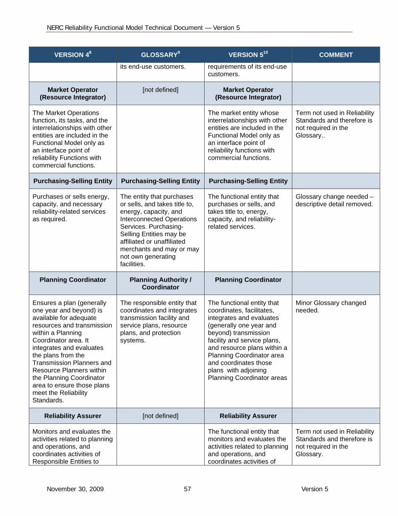
NERC Reliability Functional Model Technical Document — Version 5
November 30, 2009 57 Version 5
VERSION 48 GLOSSARY9 VERSION 510 COMMENT
its end-use customers. requirements of its end-use customers.
Market Operator (Resource Integrator)
[not defined] Market Operator (Resource Integrator)
The Market Operations function, its tasks, and the interrelationships with other entities are included in the Functional Model only as an interface point of reliability Functions with commercial functions.
The market entity whose interrelationships with other entities are included in the Functional Model only as an interface point of reliability functions with commercial functions.
Term not used in Reliability Standards and therefore is not required in the Glossary..
Purchasing-Selling Entity Purchasing-Selling Entity Purchasing-Selling Entity
Purchases or sells energy, capacity, and necessary reliability-related services as required.
The entity that purchases or sells, and takes title to, energy, capacity, and Interconnected Operations Services. Purchasing-Selling Entities may be affiliated or unaffiliated merchants and may or may not own generating facilities.
The functional entity that purchases or sells, and takes title to, energy, capacity, and reliability-related services.
Glossary change needed – descriptive detail removed.
Planning Coordinator Planning Authority / Coordinator
Planning Coordinator
Ensures a plan (generally one year and beyond) is available for adequate resources and transmission within a Planning Coordinator area. It integrates and evaluates the plans from the Transmission Planners and Resource Planners within the Planning Coordinator area to ensure those plans meet the Reliability Standards.
The responsible entity that coordinates and integrates transmission facility and service plans, resource plans, and protection systems.
The functional entity that coordinates, facilitates, integrates and evaluates (generally one year and beyond) transmission facility and service plans, and resource plans within a Planning Coordinator area and coordinates those plans with adjoining Planning Coordinator areas
Minor Glossary changed needed.
Reliability Assurer [not defined] Reliability Assurer
Monitors and evaluates the activities related to planning and operations, and coordinates activities of Responsible Entities to
The functional entity that monitors and evaluates the activities related to planning and operations, and coordinates activities of
Term not used in Reliability Standards and therefore is not required in the Glossary.
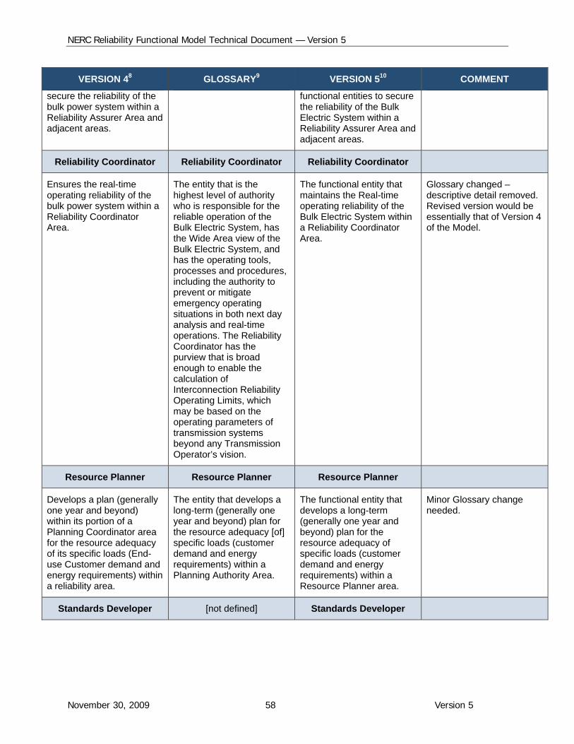
NERC Reliability Functional Model Technical Document — Version 5
November 30, 2009 58 Version 5
VERSION 48 GLOSSARY9 VERSION 510 COMMENT
secure the reliability of the bulk power system within a Reliability Assurer Area and adjacent areas.
functional entities to secure the reliability of the Bulk Electric System within a Reliability Assurer Area and adjacent areas.
Reliability Coordinator Reliability Coordinator Reliability Coordinator
Ensures the real-time operating reliability of the bulk power system within a Reliability Coordinator Area.
The entity that is the highest level of authority who is responsible for the reliable operation of the Bulk Electric System, has the Wide Area view of the Bulk Electric System, and has the operating tools, processes and procedures, including the authority to prevent or mitigate emergency operating situations in both next day analysis and real-time operations. The Reliability Coordinator has the purview that is broad enough to enable the calculation of Interconnection Reliability Operating Limits, which may be based on the operating parameters of transmission systems beyond any Transmission Operator’s vision.
The functional entity that maintains the Real-time operating reliability of the Bulk Electric System within a Reliability Coordinator Area.
Glossary changed – descriptive detail removed. Revised version would be essentially that of Version 4 of the Model.
Resource Planner Resource Planner Resource Planner
Develops a plan (generally one year and beyond) within its portion of a Planning Coordinator area for the resource adequacy of its specific loads (End-use Customer demand and energy requirements) within a reliability area.
The entity that develops a long-term (generally one year and beyond) plan for the resource adequacy [of] specific loads (customer demand and energy requirements) within a Planning Authority Area.
The functional entity that develops a long-term (generally one year and beyond) plan for the resource adequacy of specific loads (customer demand and energy requirements) within a Resource Planner area.
Minor Glossary change needed.
Standards Developer [not defined] Standards Developer
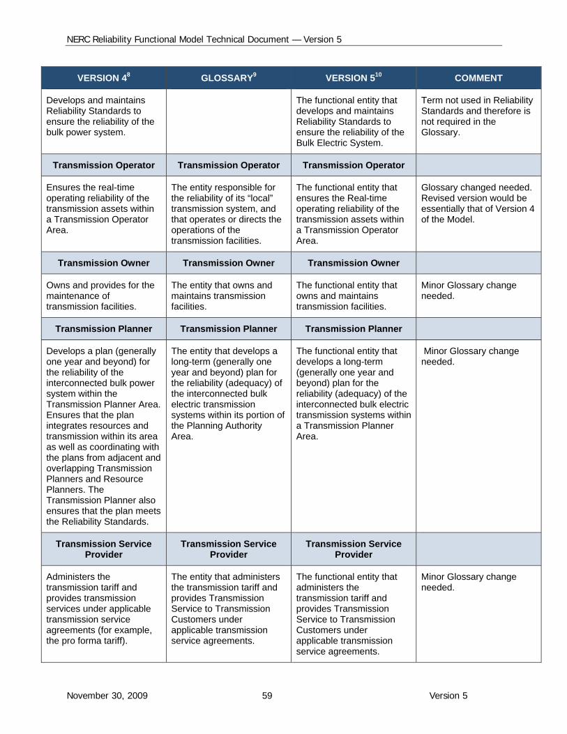
NERC Reliability Functional Model Technical Document — Version 5
November 30, 2009 59 Version 5
VERSION 48 GLOSSARY9 VERSION 510 COMMENT
Develops and maintains Reliability Standards to ensure the reliability of the bulk power system.
The functional entity that develops and maintains Reliability Standards to ensure the reliability of the Bulk Electric System.
Term not used in Reliability Standards and therefore is not required in the Glossary.
Transmission Operator Transmission Operator Transmission Operator
Ensures the real-time operating reliability of the transmission assets within a Transmission Operator Area.
The entity responsible for the reliability of its “local” transmission system, and that operates or directs the operations of the transmission facilities.
The functional entity that ensures the Real-time operating reliability of the transmission assets within a Transmission Operator Area.
Glossary changed needed. Revised version would be essentially that of Version 4 of the Model.
Transmission Owner Transmission Owner Transmission Owner
Owns and provides for the maintenance of transmission facilities.
The entity that owns and maintains transmission facilities.
The functional entity that owns and maintains transmission facilities.
Minor Glossary change needed.
Transmission Planner Transmission Planner Transmission Planner
Develops a plan (generally one year and beyond) for the reliability of the interconnected bulk power system within the Transmission Planner Area. Ensures that the plan integrates resources and transmission within its area as well as coordinating with the plans from adjacent and overlapping Transmission Planners and Resource Planners. The Transmission Planner also ensures that the plan meets the Reliability Standards.
The entity that develops a long-term (generally one year and beyond) plan for the reliability (adequacy) of the interconnected bulk electric transmission systems within its portion of the Planning Authority Area.
The functional entity that develops a long-term (generally one year and beyond) plan for the reliability (adequacy) of the interconnected bulk electric transmission systems within a Transmission Planner Area.
Minor Glossary change needed.
Transmission Service Provider
Transmission Service Provider
Transmission Service Provider
Administers the transmission tariff and provides transmission services under applicable transmission service agreements (for example, the pro forma tariff).
The entity that administers the transmission tariff and provides Transmission Service to Transmission Customers under applicable transmission service agreements.
The functional entity that administers the transmission tariff and provides Transmission Service to Transmission Customers under applicable transmission service agreements.
Minor Glossary change needed.
NERC Reliability Functional Model Technical Document — Version 5
November 30, 2009 60 Version 5
1122.. Reliability Areas and Boundaries
Assets versus Geography as the Basis for Defining Areas and Boundaries
It is useful for organizations that are functional entities to specify an associated Area, which defines the portion of the Bulk Electric System within which their functional entity status applies. Moreover, by reviewing all of the Areas for a particular functional entity, it is possible to establish whether there are overlapping responsibilities or gaps, which can then be eliminated. The concept of Areas and boundaries (the interfaces between adjacent Areas) is therefore important in establishing clear responsibilities for compliance with Reliability Standards.
The Functional Model building block for defining boundaries and Areas for the functional entities that operate and plan the Bulk Electric System is electrical, namely the individual Bulk Electric System asset. That is, the building blocks are the individual transmission, generation and customer equipment assets that collectively constitute the Bulk Electric System. This enables any given Bulk Electric System asset to be associated with a single organization, with respect to any particular functional entity. This will therefore provide the basis for clear assignment of responsibility for managing the potential reliability impacts of the asset, where the specific responsibility is to be established in NERC's registration, certification and compliance processes.
It is noted that a geographic definition is not adequate in a situation where there are, for example, two Transmission Operators in a given geographic footprint, differentiated by the voltage level of the assets under their respective control. In such a situation, the use of the specific Bulk Electric System assets provides an adequate basis for defining Areas/boundaries. The NERC Rules of Procedure specify area relationships among functional entities, excerpted as follows:
2.2 Regional entities shall verify that all balancing authorities and transmission operators are under the responsibility of one and only one reliability coordinator.
2.3 Regional entities shall verify that all transmission elements of the bulk power system operated within their geographic boundaries are under the authority and control of one and only one transmission planner, planning authority, transmission owner, and transmission operator.
2.4 Regional entities shall verify that all loads and generation sources within their geographic boundaries are under the authority and control of one and only one balancing authority.
2.5 Regional entities shall verify that no geographical or electrical areas of the bulk power system within their boundaries have duplication of coverage or are lacking an entity to perform required duties and tasks as identified in the reliability standards.
NERC Reliability Functional Model Technical Document — Version 5
November 30, 2009 61 Version 5
Size Considerations Relating to Area
The Functional Model does not specify a minimum or maximum size for a reliability area. From the perspective of the Model, an organization qualifies to be the Responsible Entity for a particular Function by virtue of performing the Function’s Tasks.
Size is not a consideration in the distinction between local-area versus wide-area reliability. Local-area reliability is the responsibility of the Transmission Operator in the sense of considerations relating to the Transmission Operator’s local system or area, regardless of how large that area may be. Similarly, wide-area reliability is the responsibility of the Reliability Coordinator in the sense of considerations relating as well to the systems and areas of neighboring Reliability Coordinators, regardless of how small the Reliability Coordinator’s own area may be.
NERC Reliability Functional Model Technical Document — Version 5
November 30, 2009 62 Version 5
1133.. GGeenneerraattiinngg vveerrssuuss TTrraannssmmiissssiioonn AAsssseettss The Model does not attempt to define the boundary between generating and transmission facilities, in particular regarding facilities such as protective relays and lines that are within or in proximity to a generating plant perimeter. Such boundaries may be defined by NERC, Regional Entities or governmental authorities.
From the perspective of the Model, for a facility that is determined to be a generating facility, its owner will be a Generator Owner, and its operator a Generator Operator. Correspondingly, for a facility that is determined to be a transmission facility, its owner will be a Transmission Owner, and its operator a Transmission Operator.
It is recognized that an owner may not be the operator of its facility, as a result of delegating the operating of the facility to another party through an agreement, and that in all cases it is NERC's registration process, not the Model that determines assignment as a functional entity.
NERC Reliability Functional Model Technical Document — Version 5
November 30, 2009 63 Version 5
1144.. RRoolleess iinn LLooaadd CCuurrttaaiillmmeenntt
This section discusses the roles of the various functional entities that may be involved in load curtailment. These entities include: Reliability Coordinator, Balancing Authority, Transmission Operator, Distribution Provider and Load-Serving Entity.
Types of Load Curtailment
There are two general types of load curtailment — voluntary and non-voluntary.
A. Voluntary Load Curtailment
Voluntary load curtailments are usually arranged ahead of real time under some form of agreements — market price trigger, compensation, etc., or on a totally voluntary basis with or without any compensation. Implementation of voluntary load curtailment is intended to provide a relief to the market price in some established markets, or a relief to system demand to aid the Balancing Authority in a tight capacity/energy situation, or a relief to loading on a Distribution Provider system.
Voluntary load curtailment based on pricing structure need not be requested since it is governed by pre-arranged agreement and mechanism. Voluntary curtailments that have not been pre-arranged may need to be communicated. Since end-use customers are involved in the decision-making process and must respond to the request, and the Load-Serving Entity holds the contractual obligation to serve these customers, such requests are usually communicated to the end-use customers through the Load-Serving Entity as directed by the initiating entities, which include the Balancing Authority and the Distribution Provider, to address potential capacity/energy shortfall in the Balancing Authority area or potential overload on the Distribution Provider system.
B. Non-Voluntary Load Curtailment (Shedding)
Non-voluntary load curtailments are usually implemented in real time to address imminent or existing capacity/energy shortfalls or transmission reliability concerns such as exceedance of an IROL or SOL, or a low voltage problem. Some pre-arrangements may be made ahead of time such as identifying the amount and location of load to be shed, and specific critical loads that may be excluded from curtailment by feeder configuration. However, since implementation is often of urgent nature, a decision process involving the end-use customers and communication via the Load-Serving Entity is usually bypassed.
Depending on the need to implement this type of curtailment, load is either curtailed automatically (such as in the case of underfrequency or undervoltage load shedding), or a curtailment directive is made by the Reliability Coordinator, Balancing Authority, or Transmission Operator directly to the Distribution Provider for physical implementation (except when this can be accomplished directly by the Transmission Operator). The Distribution Provider may also have a need to curtail load to address overload problems on its system. In this case, the Distribution Provider may implement load shedding directly.
NERC Reliability Functional Model Technical Document — Version 5
November 30, 2009 64 Version 5
Role of Responsible Entities in Load Curtailment Reliability Coordinator The Reliability Coordinator maintains Real-time system reliability, which includes implementing a number of emergency actions which include directing load shedding to preserve system reliability. In addition, the Reliability Coordinator, in collaboration with the Balancing Authority and Transmission Operator, may also participate in invoking public appeals, voltage reductions, demand-side management, and even load shedding if the Balancing Authority cannot achieve resource-demand balance.
When a Reliability Coordinator has a need to direct non-voluntary load curtailment, it issues a directive to the Distribution Provider or the Transmission Operator to implement the curtailment.
Balancing Authority When a Balancing Authority anticipates or experiences a capacity or energy shortfall, it will take actions such as public appeals, demand-side management programs, and load curtailment, as necessary to maintain a resource/demand/interchange balance. As time permits, the Balancing Authority may seek voluntary load curtailment to reduce demand in its area. In this case, the Balancing Authority will communicate such a request to the Load-Serving Entity. In the event of an Energy Emergency, the Balancing Authority may direct non-voluntary load curtailment by issuing a directive to the Distribution Provider or the Transmission Operator for implementation.
Transmission Operator The Transmission Operator, in coordination with the Reliability Coordinator, can take actions such as implementing voltage reductions and implement load shedding to mitigate a transmission emergency. When a Transmission Operator sees a need for non-voluntary load curtailment to relieve transmission constraints, such as an actual or expected exceedance of an operating limit, it implements load shedding that is under its control, or directs a Distribution Provider to physically implement the curtailment.
Distribution Provider The Distribution Provider provides the facilities that could be used to shed load for emergency action. It is that entity that has the capability to physically shed load, but it is generally not responsible for directing load shedding. Loading shedding is generally directed by the Reliability Coordinator, Balancing Authority and Transmission Operator.
However, the Distribution Provide may itself initiate voluntary and non-voluntary load curtailments for its own reasons, for example to reduce its area’s demand or to mitigate overload on its system. When a Distribution Provider sees a need for voluntary load curtailment, it directs the Load-Serving Entity to communicate a request for curtailment to the end-use customers. When it sees a need to implement non-voluntary load curtailment to address a loading or voltage concern, it implements the curtailment on its own.
Load-Serving Entity
The Load-Serving Entity identifies the loads for voluntary as well as non-voluntary curtailments. For voluntary load shedding, the LSE is responsible for making contractual arrangements with end-use customers who participate in such a program, and identifying to the Balancing
NERC Reliability Functional Model Technical Document — Version 5
November 30, 2009 65 Version 5
Authorities and Distribution Providers of such arrangements so that these customers, once committed, would be put on curtailment list if and when needed to address potential capacity shortage and/or system constraints.
For voluntary load curtailment that has not been pre-arranged, the Load-Serving Entity may be directed by the Balancing Authority or Distribution Provider to communicate its curtailment requests to the end-use customers.
For non-voluntary curtailment, such as automatic underfrequency and undervoltage load shedding and manual load shedding, the Load-Serving Entity identifies which critical customer loads should be excluded from curtailment for public health, safety and/or security reasons. Once identified and necessary contractual arrangements are made, the Distribution Provider (or the Transmission Operator as appropriate) will make reasonable efforts to arrange (feeder) connection arrangement such that these critical loads will not be curtailed by the load shedding facilities until other options have been exhausted.
The Load-Serving Entity is responsible for communicating requests for voluntary curtailment to the appropriate end-use customers, thereby increasing the effectiveness of voluntary load curtailment. In some jurisdictions, it appears that the “wires” entity, i.e., the Distribution Provider, that performs these Tasks. However, from a functional model viewpoint, it is the Load-Serving Entity function within that Distribution Provider organization that performs this task.
NERC Reliability Functional Model Technical Document — Version 5
November 30, 2009 66 Version 5
1155.. HHiissttoorryy ooff RReevviissiioonnss
Version 1 Version 1 of the Model was approved in February 2002.
Version 2 Version 2 of the Model11 was approved Feb. 10, 2004.
Version 2 responded to confusion between a Function and the organization responsibility for its performance, by separately identifying the Responsible Entity associated with each Function. For example, whereas Version 1 used the single term Transmission Operator for both the Function and responsible entity, Version 2 introduced Transmission Operations as the Function (the Tasks), and Transmission Operator as the Responsible Entity for those Tasks. Corresponding changes were made for all Functions. This distinction has been maintained in subsequent versions.
The Market Operation Function and Market Operator were added to the Model to provide an interface point with commercial functions.
Version 1 contained only operating Functions. Version 2 introduced three planning Functions (Planning Reliability, Transmission Planning, Resource Planning) and three associated Responsible Entities (: Planning Authority, Transmission Planner and Resource Planner).
Version 3 Version 3 of the Model was approved February 13, 2007.12 It addressed a number of issues that arose as NERC transitioned to new, mandatory and enforceable reliability standards. Several of these issues were outlined in a final report issued by the Functional Model-Reliability Standards Coordination Task Force (FMRSCTF) in March 2005.13 The FMRSCTF was established to ensure alignment between the Model and the new NERC standards being developed.
The changes introduced in Version 3 included:
The Reliability Authority entity name was changed to Reliability Coordinator, for consistency with terminology used in reliability standards.
Changes were made to more clearly define the Transmission Operations Tasks and the relationship of the Transmission Operator with the Reliability Coordinator
Changes were made to the Interchange Coordinator to accommodate the practice of Balancing Authority-to-Balancing Authority interchange scheduling
The Planning Authority was renamed the Planning Coordinator
11 See ftp://www.nerc.com/pub/sys/all_updl/oc/fmrtg/Functional_Model_Version_2.pdf. 12 See ftp://www.nerc.com/pub/sys/all_updl/oc/fmrtg/Function_Model_Version3_Board_Approved_13Feb07.pdf. 13 Final Report of the Functional Model — Reliability Standards Coordination Task Force (“ FMRSCTF”), approved March 11, 2005. See ftp://www.nerc.com/pub/sys/all_updl/sac/fmrsctf/FMRSC_TF_Report_3-11-05.pdf.
NERC Reliability Functional Model Technical Document — Version 5
November 30, 2009 67 Version 5
The Regional Reliability Assurance Function and the Regional Reliability Organization Responsible Entity were added.
It was clarified that “area” of responsibility for a particular Responsible Entity’s applied to the collection of Bulk Electric System assets associated with the entity, that is, that area was defined electrically, not geographically.
Version 4 Version 4 included the following changes from Version 3:
The names Regional Reliability Assurance / Regional Reliability Organization were changed to Reliability Assurance / Reliability Assurer.
The name changes reflect the view that reliability assurance could be performed on other than a regional basis. Moreover, the functional entity need not be a Regional Entity.
The names Compliance Monitoring / Compliance Monitor were changed to Compliance Enforcement / Compliance Enforcement Authority.
The changes were judged to better reflect the strong role of compliance in the ERO regime.
The wording was changed in a number of instances to ensure that the Model’s Tasks and relationships between Responsible Entities do not specify prescriptive requirements. Prescriptive requirements are specified in reliability standards and NERC processes, not in the Model.
For example, references in Version 2 that a Responsible Entity “must ensure” or “is required to ensure” were changed in Version 4 to simply “ensures”.
It was clarified that the Generator Owner and Transmission Owner provide for the maintenance of their respective assets.
This recognizes that the performance of the maintenance may be assigned by the owner to another party, for example, to a Generator Operator or Transmission Operator, respectively.
Version 5 Version 5 introduces the following changes:
Entity name
Interchange Authority has been changed to Interchange Coordinator. Also incorporated are the terms Arranged and Confirmed Interchange to be consistent with terminology used in the INT standards.
Terminology The term “responsible entity” in the Model has been changed to “functional entity”.
o The usage of “responsible” in Version 4 derived from an earlier version of the Model. Version 4 clarified that the Model is limited to describing the performance of tasks, but not compliance aspects such as responsibility for such performance. Version 5 takes this clarification one step further by replacing the term “responsible” in the Model.
NERC Reliability Functional Model Technical Document — Version 5
November 30, 2009 68 Version 5
o The Model uses the term functional entity to apply to a class of entity, such as a Balancing Authority, and makes no reference to the specific organizations that register as functional entities.
o Reliability is best served if there is consistency of definitions within all NERC documents. These documents include, but are not limited to, the Functional Model, the NERC Rules of Procedure and Glossary of Terms.
Entity definitions
The Model has been revised to define the various functional entities, not the functions, consistent with the approach used in the Glossary and standards.
The functional entity definitions have been revised.
o The form of the definitions is uniform, with each definition beginning: “The functional entity that…”
o Each definition is single sentence, limited to a simple statement of the nature of the tasks performed. As a result some of the current descriptive wording in Version 4 or Glossary definitions has been removed in the Version 5 definitions.