Embed Size (px)
Citation preview
ModelSim®A d v a n c e d V e r i f i c a t i o n a n d D e b u g g i n g
XilinxTutorialV e r s i o n 6 . 0 a
P u b l i s h e d : S e p t e m b e r 2 4 , 2 0 0 4
T-2
M
This document is for information and instruction purposes. Mentor Graphics reserves the right to make changes in specifications and other information contained in this publication without prior notice, and the reader should, in all cases, consult Mentor Graphics to determine whether any changes have been made.
The terms and conditions governing the sale and licensing of Mentor Graphics products are set forth in written agreements between Mentor Graphics and its customers. No representation or other affirmation of fact contained in this publication shall be deemed to be a warranty or give rise to any liability of Mentor Graphics whatsoever.
MENTOR GRAPHICS MAKES NO WARRANTY OF ANY KIND WITH REGARD TO THIS MATERIAL INCLUDING, BUT NOT LIMITED TO, THE IMPLIED WARRANTIES OR MERCHANTABILITY AND FITNESS FOR A PARTICULAR PURPOSE.
MENTOR GRAPHICS SHALL NOT BE LIABLE FOR ANY INCIDENTAL, INDIRECT, SPECIAL, OR CONSEQUENTIAL DAMAGES WHATSOEVER (INCLUDING BUT NOT LIMITED TO LOST PROFITS) ARISING OUT OF OR RELATED TO THIS PUBLICATION OR THE INFORMATION CONTAINED IN IT, EVEN IF MENTOR GRAPHICS CORPORATION HAS BEEN ADVISED OF THE POSSIBILITY OF SUCH DAMAGES.
R
UanGwC
odelSim Tutorial
ESTRICTED RIGHTS LEGEND 03/97
.S. Government Restricted Rights. The SOFTWARE and documentation have been developed entirely at private expense d are commercial computer software provided with restricted rights. Use, duplication or disclosure by the U.S. overnment or a U.S. Government subcontractor is subject to the restrictions set forth in the license agreement provided ith the software pursuant to DFARS 227.7202-3(a) or as set forth in subparagraph (c)(1) and (2) of the Commercial omputer Software - Restricted Rights clause at FAR 52.227-19, as applicable.
ModelSim Tutorial
T-3
Table of Contents
Introduction . . . . . . . . . . . . . . . . . . . . . . . . . . . . . . . . . . . . . . . . . . . . . . .T-5
Lesson 1 - ModelSim conceptual overview . . . . . . . . . . . . . . . . . . . . . . .T-9
Lesson 2 - Basic simulation . . . . . . . . . . . . . . . . . . . . . . . . . . . . . . . . . .T-17
Lesson 3 - ModelSim projects . . . . . . . . . . . . . . . . . . . . . . . . . . . . . . . .T-29
Lesson 4 - Working with multiple libraries . . . . . . . . . . . . . . . . . . . . . . .T-39
L
L
L
T
In
esson 5 - Viewing simulations in the Wave window . . . . . . . . . . . . . . .T-49
esson 6 - Viewing and initializing memories . . . . . . . . . . . . . . . . . . . .T-59
esson 7 - Automating ModelSim . . . . . . . . . . . . . . . . . . . . . . . . . . . . .T-73
-83
dex . . . . . . . . . . . . . . . . . . . . . . . . . . . . . . . . . . . . . . . . . . . . . . . . . . .T-89

T-4
Mo
delSim Tutorial
ModelSim Tutorial
T-5
Introduction
Topics
The following topics are covered in this chapter:
Assumptions . . . . . . . . . . . . . . . . . . . . . . . . . T-6
Before you begin . . . . . . . . . . . . . . . . . . . . . . . . T-8Example designs . . . . . . . . . . . . . . . . . . . . . . . T-8
T-6 Introduction
Mo
Assumptions
We assume that you are familiar with the use of your operating system. If you are not familiar with Microsoft Windows, we recommend that you work through the tutorials provided with MS Windows before using ModelSim.
We also assume that you have a working knowledge of VHDL and/or Verilog. Although ModelSim is an excellent tool to use while learning HDL concepts and practices, this document is not written to support that goal.
delSim Tutorial
Where to find our documentation T-7
ModelSim Tutorial
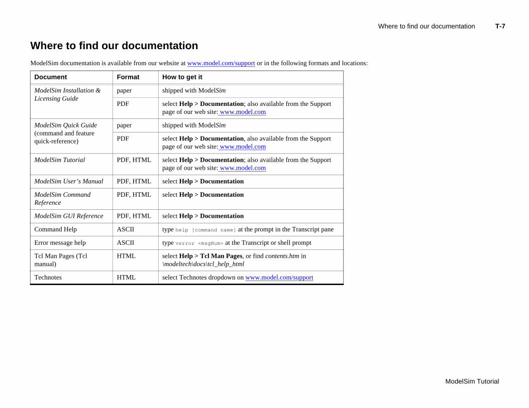
Where to find our documentation
ModelSim documentation is available from our website at www.model.com/support or in the following formats and locations:
Document Format How to get it
ModelSim Installation & Licensing Guide
paper shipped with ModelSim
PDF select Help > Documentation; also available from the Support page of our web site: www.model.com
ModelSim Quick Guide (command and feature q
paper shipped with ModelSim
M
M
MR
M
C
E
Tm
T
uick-reference) PDF select Help > Documentation, also available from the Support page of our web site: www.model.com
odelSim Tutorial PDF, HTML select Help > Documentation; also available from the Support page of our web site: www.model.com
odelSim User’s Manual PDF, HTML select Help > Documentation
odelSim Command eference
PDF, HTML select Help > Documentation
odelSim GUI Reference PDF, HTML select Help > Documentation
ommand Help ASCII type help [command name] at the prompt in the Transcript pane
rror message help ASCII type verror <msgNum> at the Transcript or shell prompt
cl Man Pages (Tcl anual)
HTML select Help > Tcl Man Pages, or find contents.htm in \modeltech\docs\tcl_help_html
echnotes HTML select Technotes dropdown on www.model.com/support
T-8 Introduction
Mo
Before you begin
Preparation for some of the lessons leaves certain details up to you. You will decide the best way to create directories, copy files, and execute programs within your operating system. (When you are operating the simulator within ModelSim’s GUI, the interface is consistent for all platforms.)
Example designs
ModelSim comes with Verilog and VHDL versions of the designs used in these lessons. This allows you to do the tutorial regardless of which license type you have. Though we have tried to minimize the differences between the Verilog and VHDL versions, we could not do so in all cases. In cases where the designs differ (e.g., line numbers or syntax), you will find language-specific instructions. Follow the instructions that are appropriate for the language that you are using.
delSim Tutorial
ModelSim Tutorial
T-9
Lesson 1 - ModelSim conceptual overview
Topics
The following topics are covered in this chapter:
Introduction . . . . . . . . . . . . . . . . . . . . . . . . . T-10
Basic simulation flow . . . . . . . . . . . . . . . . . . . . . . T-11Creating the working library . . . . . . . . . . . . . . . . . . . T-11Compiling your design . . . . . . . . . . . . . . . . . . . . . T-11
Pr
M
De
Running the simulation . . . . . . . . . . . . . . . . . . . . . T-11Debugging your results . . . . . . . . . . . . . . . . . . . . . T-12
oject flow . . . . . . . . . . . . . . . . . . . . . . . . . T-13
ultiple library flow . . . . . . . . . . . . . . . . . . . . . . . T-14
bugging tools . . . . . . . . . . . . . . . . . . . . . . . . T-15
T-10 Lesson -
Mo
Introduction
ModelSim is a simulation and debugging tool for VHDL, Verilog, and mixed-language designs.
This lesson provides a brief conceptual overview of the ModelSim simulation environment. It is divided into four topics, which you will learn more about in subsequent lessons:
Topic Additional information and practice
Basic simulation flow Lesson 2 - Basic simulation
Project flow Lesson 3 - ModelSim projects
M
D
delSim Tutorial
ultiple library flow Lesson 4 - Working with multiple libraries
ebugging tools Remaining lessons
Basic simulation flow T-11
ModelSim Tutorial
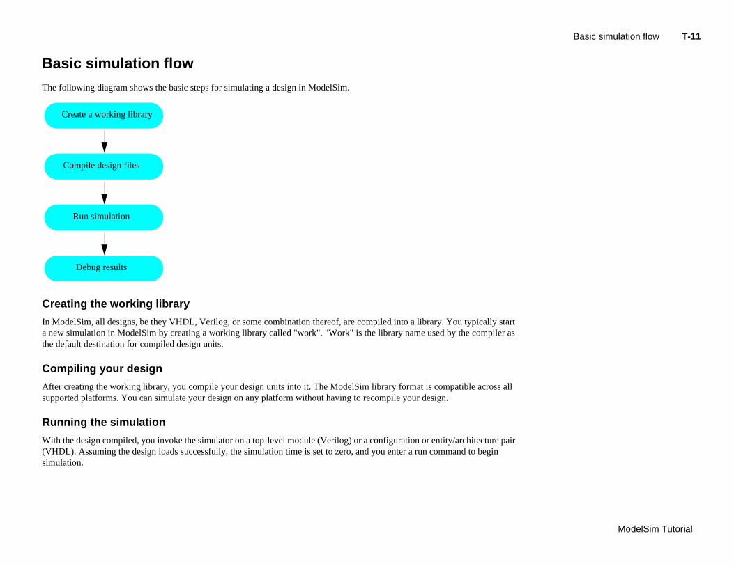
Basic simulation flow
The following diagram shows the basic steps for simulating a design in ModelSim.
C
In rt a n s the
C
Af l su
R
W ir (Vsim
Create a working library
Compile design files
reating the working library
ModelSim, all designs, be they VHDL, Verilog, or some combination thereof, are compiled into a library. You typically staew simulation in ModelSim by creating a working library called "work". "Work" is the library name used by the compiler a default destination for compiled design units.
ompiling your design
ter creating the working library, you compile your design units into it. The ModelSim library format is compatible across alpported platforms. You can simulate your design on any platform without having to recompile your design.
unning the simulation
ith the design compiled, you invoke the simulator on a top-level module (Verilog) or a configuration or entity/architecture paHDL). Assuming the design loads successfully, the simulation time is set to zero, and you enter a run command to begin ulation.
Run simulation
Debug results
T-12 Lesson -
Mo
Debugging your results
If you don’t get the results you expect, you can use ModelSim’s robust debugging environment to track down the cause of the problem.
delSim Tutorial
Project flow T-13
ModelSim Tutorial
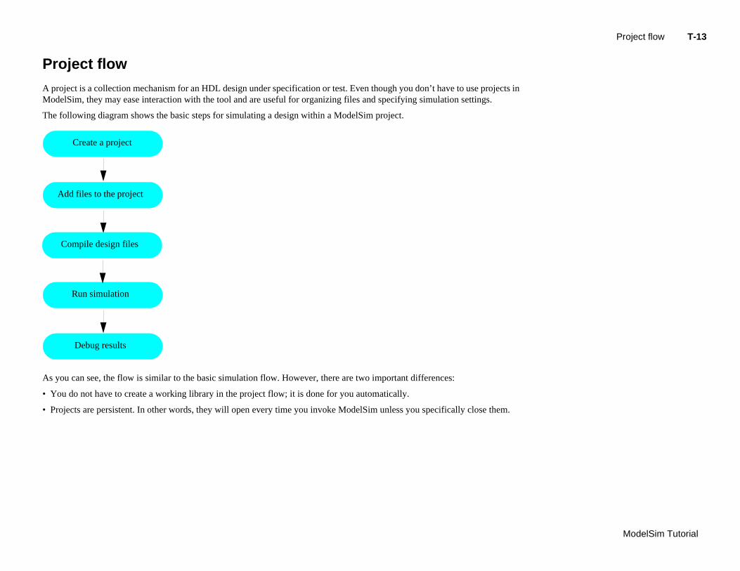
Project flow
A project is a collection mechanism for an HDL design under specification or test. Even though you don’t have to use projects in ModelSim, they may ease interaction with the tool and are useful for organizing files and specifying simulation settings.
The following diagram shows the basic steps for simulating a design within a ModelSim project.
As
• Y
• P
Create a project
you can see, the flow is similar to the basic simulation flow. However, there are two important differences:
ou do not have to create a working library in the project flow; it is done for you automatically.
rojects are persistent. In other words, they will open every time you invoke ModelSim unless you specifically close them.
Add files to the project
Run simulation
Debug results
Compile design files
T-14 Lesson -
Mo
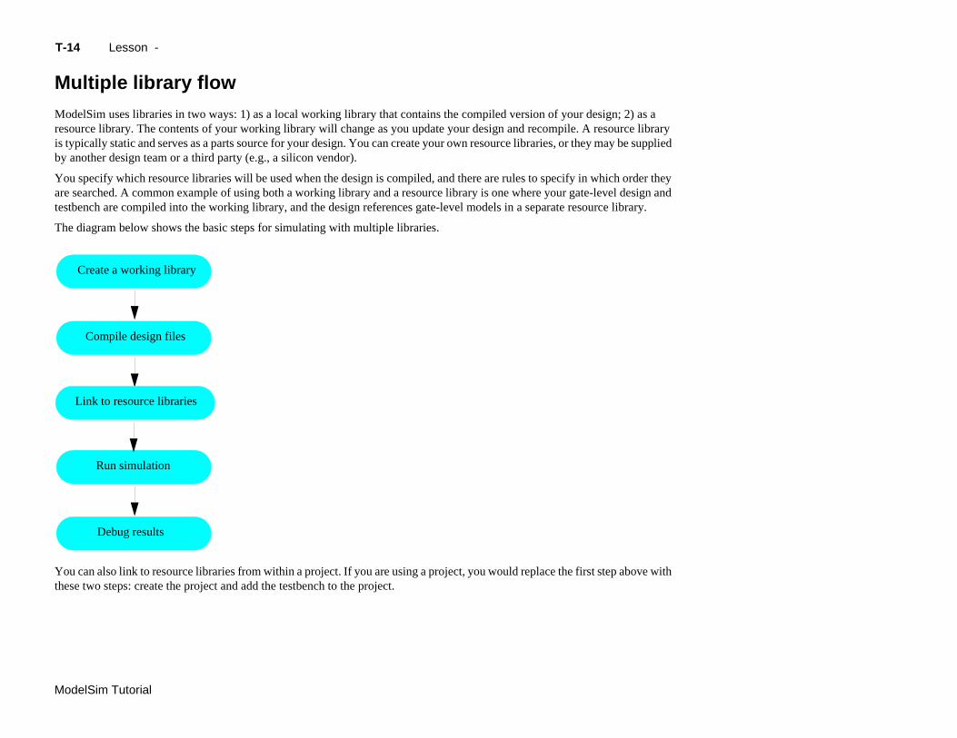
Multiple library flow
ModelSim uses libraries in two ways: 1) as a local working library that contains the compiled version of your design; 2) as a resource library. The contents of your working library will change as you update your design and recompile. A resource library is typically static and serves as a parts source for your design. You can create your own resource libraries, or they may be supplied by another design team or a third party (e.g., a silicon vendor).
You specify which resource libraries will be used when the design is compiled, and there are rules to specify in which order they are searched. A common example of using both a working library and a resource library is one where your gate-level design and testbench are compiled into the working library, and the design references gate-level models in a separate resource library.
The diagram below shows the basic steps for simulating with multiple libraries.
Yo h the
delSim Tutorial
u can also link to resource libraries from within a project. If you are using a project, you would replace the first step above witse two steps: create the project and add the testbench to the project.
Create a working library
Compile design files
Run simulation
Debug results
Link to resource libraries
Debugging tools T-15
ModelSim Tutorial
Debugging tools
ModelSim offers numerous tools for debugging and analyzing your design. Several of these tools are covered in subsequent lessons, including:
• Setting breakpoints and stepping through the source code
• Viewing waveforms and measuring time
• Viewing and initializing memories

T-16 Lesson -
Mo
delSim Tutorial
ModelSim Tutorial
T-17
Lesson 2 - Basic simulation
Topics
The following topics are covered in this lesson:
Introduction . . . . . . . . . . . . . . . . . . . . . . . . . T-18Design files for this lesson . . . . . . . . . . . . . . . . . . . . T-18Related reading . . . . . . . . . . . . . . . . . . . . . . . T-18
Creating the working design library . . . . . . . . . . . . . . . . . . . T-19
Compiling the design. . . . . . . . . . . . . . . . . . . . . . . T-21
Lo
Ru
Se
Le
ading the design into the simulator . . . . . . . . . . . . . . . . . . T-22
nning the simulation . . . . . . . . . . . . . . . . . . . . . . T-23
tting breakpoints and stepping in the Source window. . . . . . . . . . . . . . T-25
sson wrap-up . . . . . . . . . . . . . . . . . . . . . . . . T-27
T-
Mo
In
In
D
Thas
Ve
VH
Thhaa mvic
R
MVe
Mvc
delSim Tutorial
DL – <install_dir>/modeltech/examples/counter.vhd and tcounter.vhd
is lesson uses the Verilog files counter.v and tcounter.v in the examples. If you ve a VHDL license, use counter.vhd and tcounter.vhd instead. Or, if you have
ixed license, feel free to use the Verilog testbench with the VHDL counter or e versa.
elated reading
odelSim User’s Manual – Chapter 3 - Design libraries (UM-45), Chapter 5 - rilog simulation (UM-91), Chapter 4 - VHDL simulation (UM-59)
odelSim Command Reference (vlib (CR-207), vmap (CR-217), vlog (CR-208), om (CR-171), (CR-217), view (CR-183), and run (CR-135) commands)
18 Lesson -
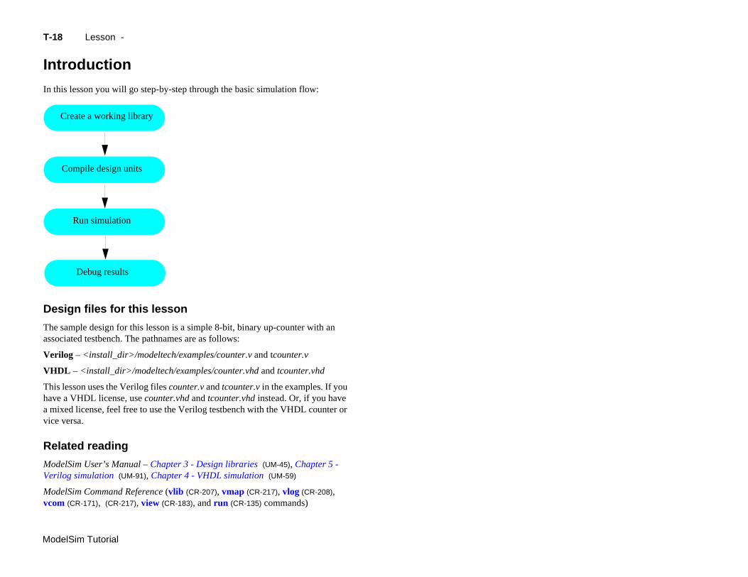
troduction
this lesson you will go step-by-step through the basic simulation flow:
esign files for this lesson
e sample design for this lesson is a simple 8-bit, binary up-counter with an sociated testbench. The pathnames are as follows:
rilog – <install_dir>/modeltech/examples/counter.v and tcounter.v
Compile design units
Run simulation
Debug results
Create a working library
Creating the working design library T-19
ModelSim Tutorial
C
Beso
1
2
3
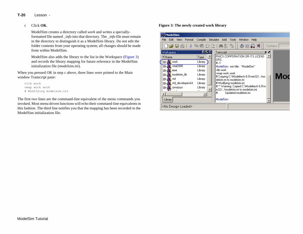
This opens a dialog where you specify physical and logical names for the
lSim dialog
rary dialog
3b
library (Figure 2). You can create a new library or map to an existing library. We’ll be doing the former.
b Type work in the Library Name field if it isn’t entered automatically.
reating the working design library
fore you can simulate a design, you must first create a library and compile the urce code into that library.
Create a new directory and copy the tutorial files into it.
Start by creating a new directory for this exercise (in case other users will be working with these lessons).
Verilog: Copy counter.v and tcounter.v files from /<install_dir>/examples to the new directory.
VHDL: Copy counter.vhd and tcounter.vhd files from /<install_dir>/examples to the new directory.
Start ModelSim if necessary.
a Type vsim at a UNIX shell prompt or use the ModelSim icon in Windows.
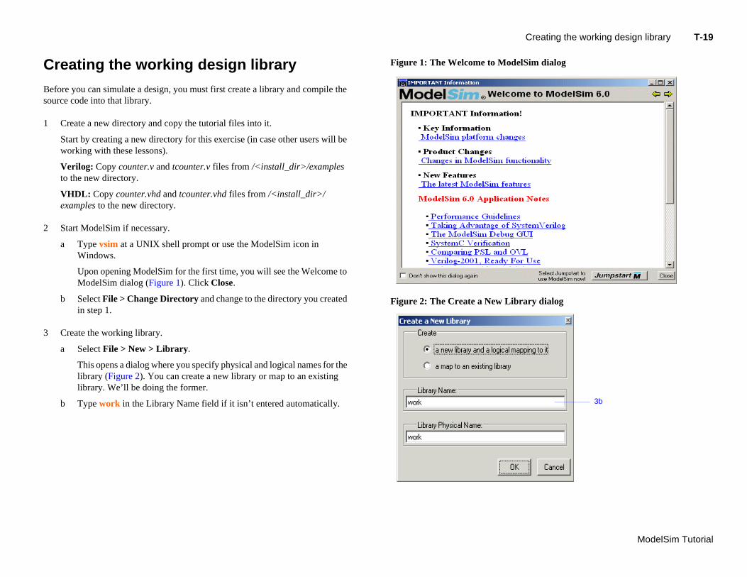
Upon opening ModelSim for the first time, you will see the Welcome to ModelSim dialog (Figure 1). Click Close.
b Select File > Change Directory and change to the directory you created in step 1.
Create the working library.
a Select File > New > Library.
Figure 1: The Welcome to Mode
Figure 2: The Create a New Lib
T-
Mo
Wwi
ThinvthiM
rk library
delSim Tutorial
20 Lesson -
c Click OK.
ModelSim creates a directory called work and writes a specially-formatted file named _info into that directory. The _info file must remain in the directory to distinguish it as a ModelSim library. Do not edit the folder contents from your operating system; all changes should be made from within ModelSim.
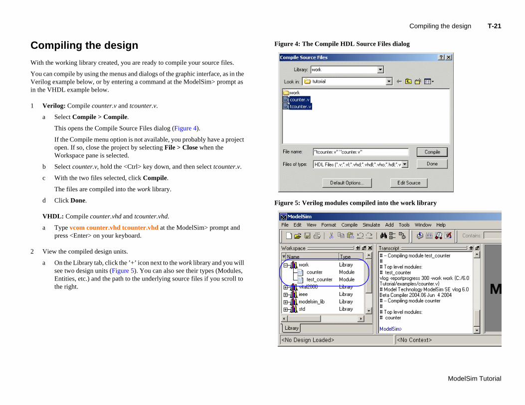
ModelSim also adds the library to the list in the Workspace (Figure 3) and records the library mapping for future reference in the ModelSim initialization file (modelsim.ini).
hen you pressed OK in step c above, three lines were printed to the Main ndow Transcript pane:
vlib workvmap work work# Modifying modelsim.ini
e first two lines are the command-line equivalent of the menu commands you oked. Most menu driven functions will echo their command-line equivalents in s fashion. The third line notifies you that the mapping has been recorded in the odelSim initialization file.
Figure 3: The newly created wo
Compiling the design T-21
ModelSim Tutorial
C
W
YoVein
1
2
rce Files dialog
iled into the work library
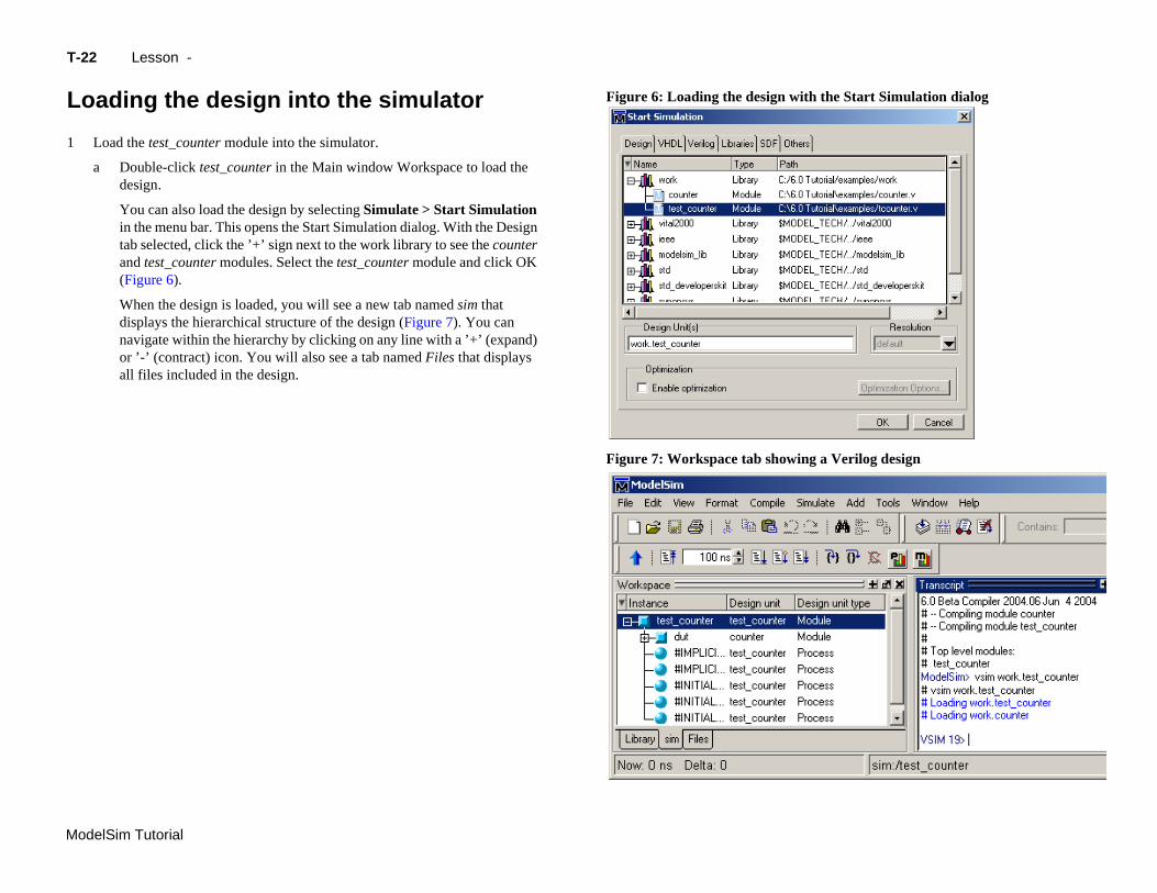
a On the Library tab, click the ’+’ icon next to the work library and you will see two design units (Figure 5). You can also see their types (Modules, Entities, etc.) and the path to the underlying source files if you scroll to the right.
ompiling the design
ith the working library created, you are ready to compile your source files.
u can compile by using the menus and dialogs of the graphic interface, as in the rilog example below, or by entering a command at the ModelSim> prompt as the VHDL example below.
Verilog: Compile counter.v and tcounter.v.
a Select Compile > Compile.
This opens the Compile Source Files dialog (Figure 4).
If the Compile menu option is not available, you probably have a project open. If so, close the project by selecting File > Close when the Workspace pane is selected.
b Select counter.v, hold the <Ctrl> key down, and then select tcounter.v.
c With the two files selected, click Compile.
The files are compiled into the work library.
d Click Done.
VHDL: Compile counter.vhd and tcounter.vhd.
a Type vcom counter.vhd tcounter.vhd at the ModelSim> prompt and press <Enter> on your keyboard.
View the compiled design units.
Figure 4: The Compile HDL Sou
Figure 5: Verilog modules comp
T-
Mo
L
1
th the Start Simulation dialog
ng a Verilog design
delSim Tutorial
22 Lesson -
oading the design into the simulator
Load the test_counter module into the simulator.
a Double-click test_counter in the Main window Workspace to load the design.
You can also load the design by selecting Simulate > Start Simulation in the menu bar. This opens the Start Simulation dialog. With the Design tab selected, click the ’+’ sign next to the work library to see the counter and test_counter modules. Select the test_counter module and click OK (Figure 6).
When the design is loaded, you will see a new tab named sim that displays the hierarchical structure of the design (Figure 7). You can navigate within the hierarchy by clicking on any line with a ’+’ (expand) or ’-’ (contract) icon. You will also see a tab named Files that displays all files included in the design.
Figure 6: Loading the design wi
Figure 7: Workspace tab showi
Running the simulation T-23
ModelSim Tutorial
R
No
1
2
3
b Type run 500 at the VSIM> prompt in the Main window.
ave window
the Wave window
2c
The simulation advances another 500 ns for a total of 600 ns (Figure 9).
unning the simulation
w you will run the simulation.
Set the graphic user interface to view all debugging windows.
a Select View > Debug Windows > All Windows.
This opens all ModelSim windows, giving you different views of your design data and a variety of debugging tools. Most windows will open as panes within the Main window. The Dataflow, List, and Wave windows will open as separate windows. You may need to move or resize the windows to your liking. Panes within the Main window can be undocked to stand alone.
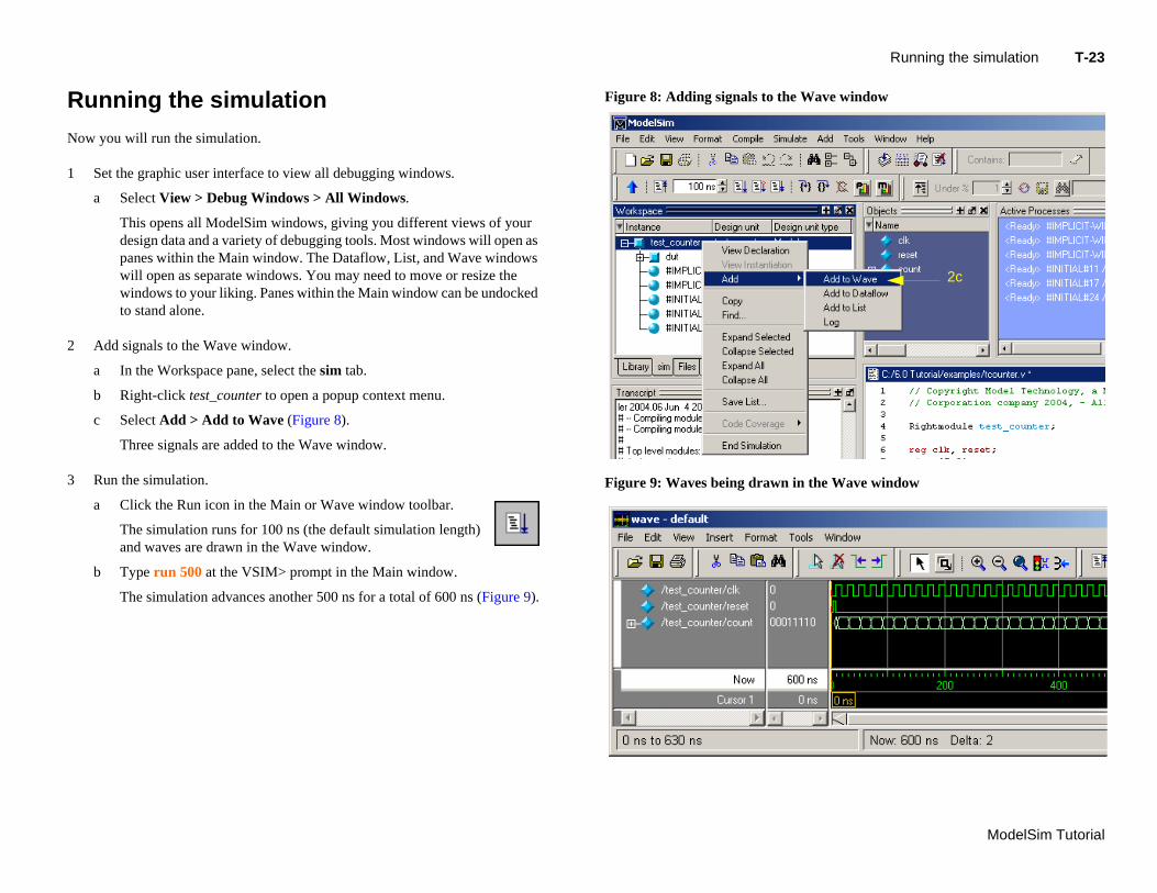
Add signals to the Wave window.
a In the Workspace pane, select the sim tab.
b Right-click test_counter to open a popup context menu.
c Select Add > Add to Wave (Figure 8).
Three signals are added to the Wave window.
Run the simulation.
a Click the Run icon in the Main or Wave window toolbar.
The simulation runs for 100 ns (the default simulation length) and waves are drawn in the Wave window.
Figure 8: Adding signals to the W
Figure 9: Waves being drawn in
T-
Mo
delSim Tutorial24 Lesson -
c Click the Run -All icon on the Main or Wave window toolbar.
The simulation continues running until you execute a break command or it hits a statement in your code (e.g., a Verilog $stop statement) that halts the simulation.
d Click the Break icon.
The simulation stops running.
and stepping in the Source window T-25
ModelSim Tutorial
SS
NeMsimon
1
2
3
Breakpoint 31.
4
ource window
d Click on line number 31 again to re-create the breakpoint.
Restart the simulation.
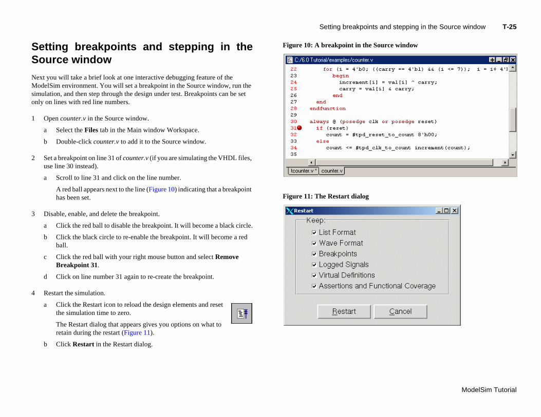
a Click the Restart icon to reload the design elements and reset the simulation time to zero.
The Restart dialog that appears gives you options on what to retain during the restart (Figure 11).
b Click Restart in the Restart dialog.
Setting breakpoints
etting breakpoints and stepping in theource window
xt you will take a brief look at one interactive debugging feature of the odelSim environment. You will set a breakpoint in the Source window, run the
ulation, and then step through the design under test. Breakpoints can be set ly on lines with red line numbers.
Open counter.v in the Source window.
a Select the Files tab in the Main window Workspace.
b Double-click counter.v to add it to the Source window.
Set a breakpoint on line 31 of counter.v (if you are simulating the VHDL files, use line 30 instead).
a Scroll to line 31 and click on the line number.
A red ball appears next to the line (Figure 10) indicating that a breakpoint has been set.
Disable, enable, and delete the breakpoint.
a Click the red ball to disable the breakpoint. It will become a black circle.
b Click the black circle to re-enable the breakpoint. It will become a red ball.
c Click the red ball with your right mouse button and select Remove
Figure 10: A breakpoint in the S
Figure 11: The Restart dialog
T-
Mo
5
inter on a variable in the Source view
Objects window
delSim Tutorial
26 Lesson -
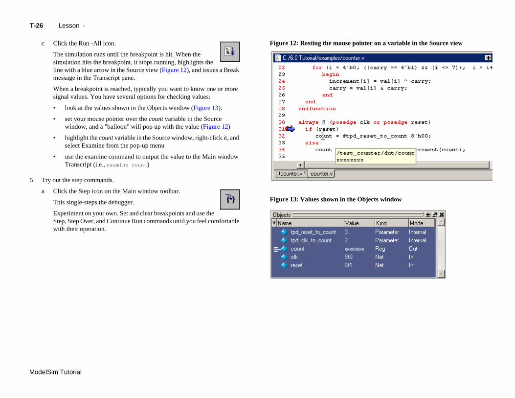
c Click the Run -All icon.
The simulation runs until the breakpoint is hit. When the simulation hits the breakpoint, it stops running, highlights the line with a blue arrow in the Source view (Figure 12), and issues a Break message in the Transcript pane.
When a breakpoint is reached, typically you want to know one or more signal values. You have several options for checking values:
• look at the values shown in the Objects window (Figure 13).
• set your mouse pointer over the count variable in the Source window, and a "balloon" will pop up with the value (Figure 12)
• highlight the count variable in the Source window, right-click it, and select Examine from the pop-up menu
• use the examine command to output the value to the Main window Transcript (i.e., examine count)
Try out the step commands.
a Click the Step icon on the Main window toolbar.
This single-steps the debugger.
Experiment on your own. Set and clear breakpoints and use the Step, Step Over, and Continue Run commands until you feel comfortable with their operation.
Figure 12: Resting the mouse po
Figure 13: Values shown in the
Lesson wrap-up T-27
ModelSim Tutorial
L
Thsim
1
2
esson wrap-up
is concludes this lesson. Before continuing we need to end the current ulation.
Select Simulate > End Simulation.
Click Yes when prompted to confirm that you wish to quit simulating.

T-
Mo
delSim Tutorial28 Lesson -
ModelSim Tutorial
T-29
Lesson 3 - ModelSim projects
Topics
The following topics are covered in this lesson:
Introduction . . . . . . . . . . . . . . . . . . . . . . . . . T-30Related reading . . . . . . . . . . . . . . . . . . . . . . . T-30
Creating a new project . . . . . . . . . . . . . . . . . . . . . . T-31Adding objects to the project . . . . . . . . . . . . . . . . . . . T-32Changing compile order (VHDL) . . . . . . . . . . . . . . . . . . T-33
Compiling and loading a design . . . . . . . . . . . . . . . . . . . . T-34
Or
Si
Le
ganizing projects with folders . . . . . . . . . . . . . . . . . . . . T-35Adding folders . . . . . . . . . . . . . . . . . . . . . . . T-35Moving files to folders . . . . . . . . . . . . . . . . . . . . . T-36
mulation Configurations . . . . . . . . . . . . . . . . . . . . . T-37
sson wrap-up . . . . . . . . . . . . . . . . . . . . . . . . T-38
T-
Mo
In
Inwoco
Thha
R
M
delSim Tutorial
30 Lesson -
troduction
this lesson you will practice creating a project. At a minimum, projects have a rk library and a session state that is stored in a .mpf file. A project may also
nsist of:
• HDL source files or references to source files
• other files such as READMEs or other project documentation
• local libraries
• references to global libraries
is lesson uses the Verilog files tcounter.v and counter.v in the examples. If you ve a VHDL license, use tcounter.vhd and counter.vhd instead.
elated reading
odelSim User’s Manual, Chapter 2 - Projects (UM-27)
Creating a new project T-31
ModelSim Tutorial
C
1
2
ialog
2b
2c
2d
reating a new project
If you just finished the previous lesson, ModelSim should already be running. If not, start ModelSim.
a Type vsim at a UNIX shell prompt or use the ModelSim icon in Windows.
Create a new project.
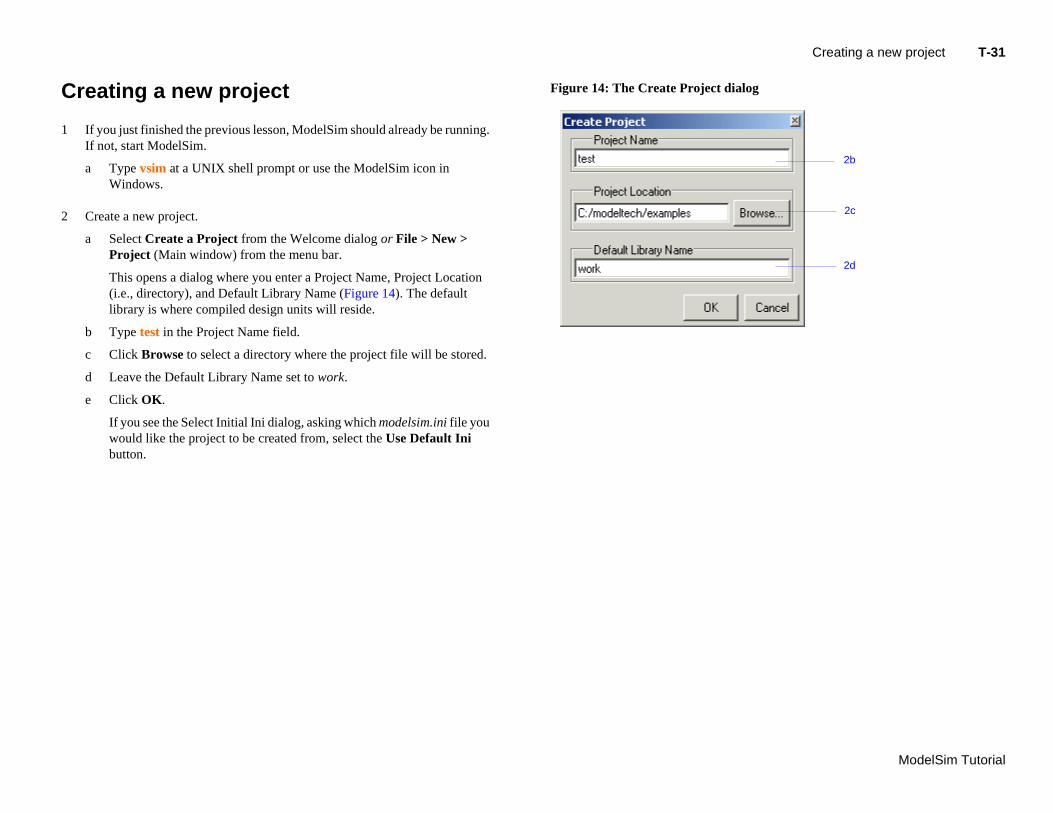
a Select Create a Project from the Welcome dialog or File > New > Project (Main window) from the menu bar.
This opens a dialog where you enter a Project Name, Project Location (i.e., directory), and Default Library Name (Figure 14). The default library is where compiled design units will reside.
b Type test in the Project Name field.
c Click Browse to select a directory where the project file will be stored.
d Leave the Default Library Name set to work.
e Click OK.
If you see the Select Initial Ini dialog, asking which modelsim.ini file you would like the project to be created from, select the Use Default Ini button.
Figure 14: The Create Project d
T-
Mo
A
Ontabdiaadco
1
a project
ct dialog
1a
1b
delSim Tutorial
32 Lesson -
dding objects to the project
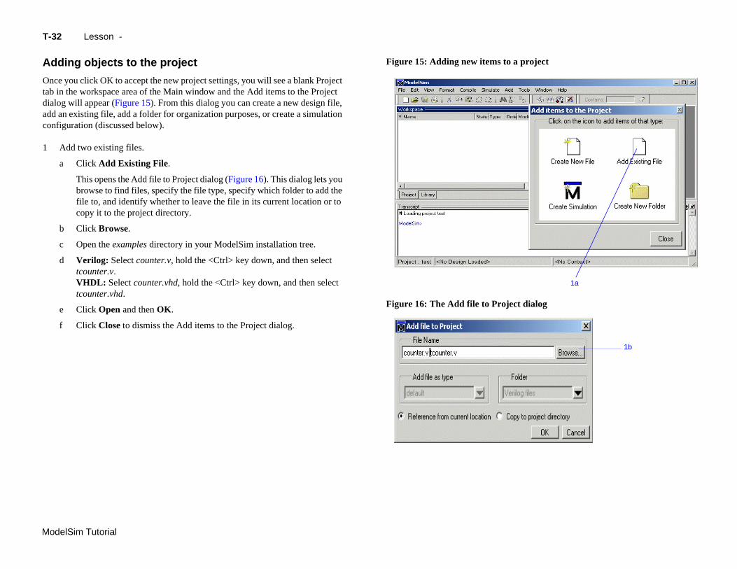
ce you click OK to accept the new project settings, you will see a blank Project in the workspace area of the Main window and the Add items to the Project log will appear (Figure 15). From this dialog you can create a new design file,
d an existing file, add a folder for organization purposes, or create a simulation nfiguration (discussed below).
Add two existing files.
a Click Add Existing File.
This opens the Add file to Project dialog (Figure 16). This dialog lets you browse to find files, specify the file type, specify which folder to add the file to, and identify whether to leave the file in its current location or to copy it to the project directory.
b Click Browse.
c Open the examples directory in your ModelSim installation tree.
d Verilog: Select counter.v, hold the <Ctrl> key down, and then select tcounter.v.VHDL: Select counter.vhd, hold the <Ctrl> key down, and then select tcounter.vhd.
e Click Open and then OK.
f Click Close to dismiss the Add items to the Project dialog.
Figure 15: Adding new items to
Figure 16: The Add file to Proje
Creating a new project T-33
ModelSim Tutorial
C
Coco
1
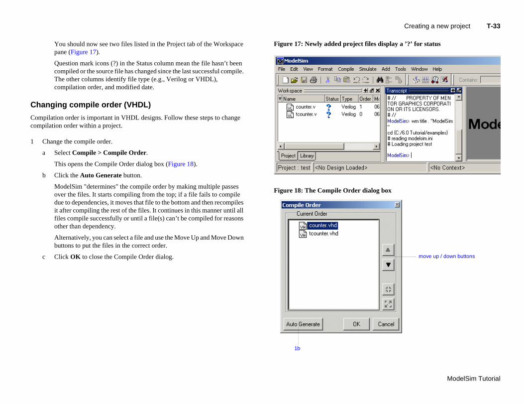
c Click OK to close the Compile Order dialog.
files display a ’?’ for status
ialog box
move up / down buttons
1b
You should now see two files listed in the Project tab of the Workspace pane (Figure 17).
Question mark icons (?) in the Status column mean the file hasn’t been compiled or the source file has changed since the last successful compile. The other columns identify file type (e.g., Verilog or VHDL), compilation order, and modified date.
hanging compile order (VHDL)
mpilation order is important in VHDL designs. Follow these steps to change mpilation order within a project.
Change the compile order.
a Select Compile > Compile Order.
This opens the Compile Order dialog box (Figure 18).
b Click the Auto Generate button.
ModelSim "determines" the compile order by making multiple passes over the files. It starts compiling from the top; if a file fails to compile due to dependencies, it moves that file to the bottom and then recompiles it after compiling the rest of the files. It continues in this manner until all files compile successfully or until a file(s) can’t be compiled for reasons other than dependency.
Alternatively, you can select a file and use the Move Up and Move Down buttons to put the files in the correct order.
Figure 17: Newly added project
Figure 18: The Compile Order d
T-
Mo
C
1
2
3
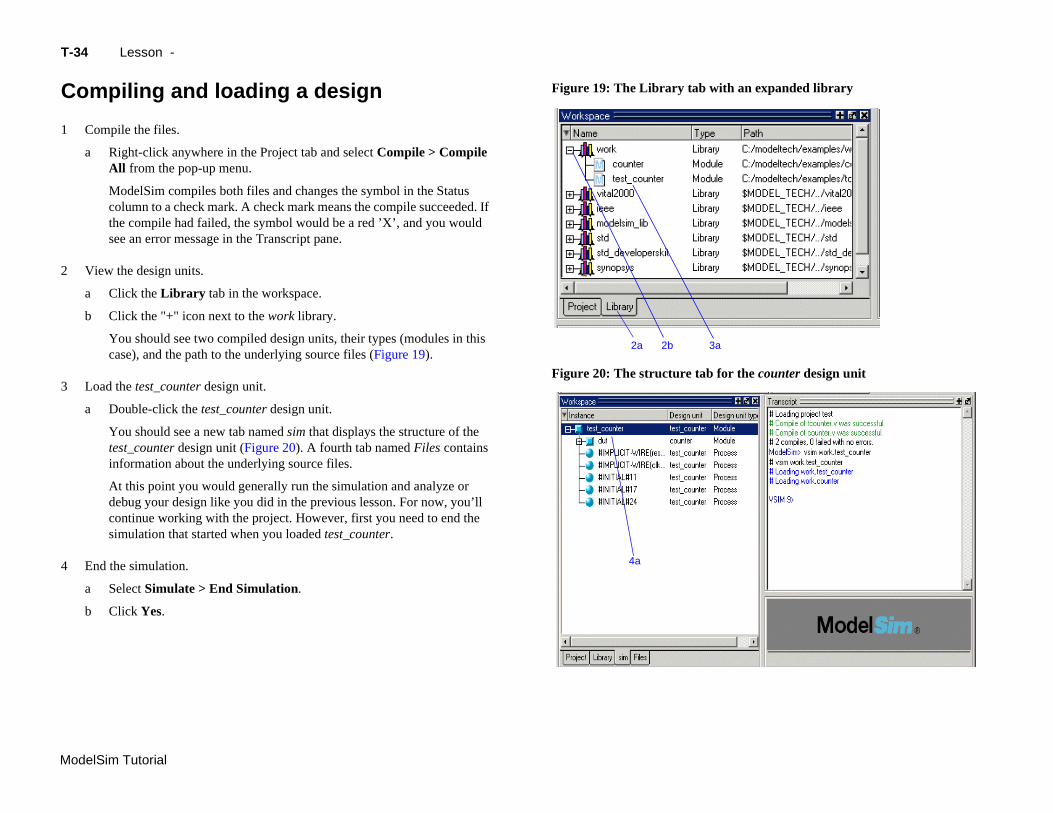
continue working with the project. However, first you need to end the
4
an expanded library
the counter design unit
delSim Tutorial
simulation that started when you loaded test_counter.
End the simulation.
a Select Simulate > End Simulation.
b Click Yes.
4a
34 Lesson -
ompiling and loading a design
Compile the files.
a Right-click anywhere in the Project tab and select Compile > Compile All from the pop-up menu.
ModelSim compiles both files and changes the symbol in the Status column to a check mark. A check mark means the compile succeeded. If the compile had failed, the symbol would be a red ’X’, and you would see an error message in the Transcript pane.
View the design units.
a Click the Library tab in the workspace.
b Click the "+" icon next to the work library.
You should see two compiled design units, their types (modules in this case), and the path to the underlying source files (Figure 19).
Load the test_counter design unit.
a Double-click the test_counter design unit.
You should see a new tab named sim that displays the structure of the test_counter design unit (Figure 20). A fourth tab named Files contains information about the underlying source files.
At this point you would generally run the simulation and analyze or debug your design like you did in the previous lesson. For now, you’ll
Figure 19: The Library tab with
Figure 20: The structure tab for
2a 2b 3a
Organizing projects with folders T-35
ModelSim Tutorial
O
If focreplafo
A
Asopme
1
2
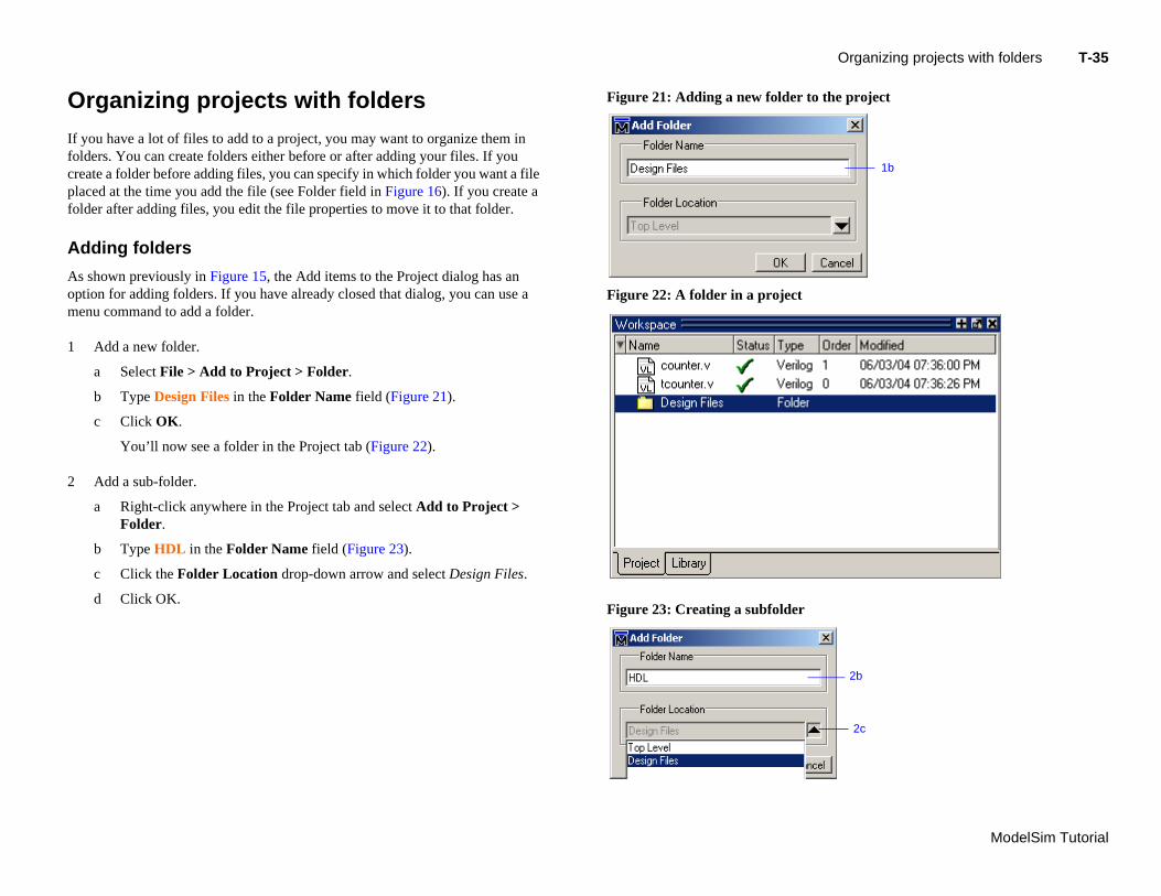
c Click the Folder Location drop-down arrow and select Design Files.
to the project
1b
2c
2b
d Click OK.Figure 23: Creating a subfolder
rganizing projects with folders
you have a lot of files to add to a project, you may want to organize them in lders. You can create folders either before or after adding your files. If you ate a folder before adding files, you can specify in which folder you want a file ced at the time you add the file (see Folder field in Figure 16). If you create a
lder after adding files, you edit the file properties to move it to that folder.
dding folders
shown previously in Figure 15, the Add items to the Project dialog has an tion for adding folders. If you have already closed that dialog, you can use a nu command to add a folder.
Add a new folder.
a Select File > Add to Project > Folder.
b Type Design Files in the Folder Name field (Figure 21).
c Click OK.
You’ll now see a folder in the Project tab (Figure 22).
Add a sub-folder.
a Right-click anywhere in the Project tab and select Add to Project > Folder.
b Type HDL in the Folder Name field (Figure 23).
Figure 21: Adding a new folder
Figure 22: A folder in a project
T-
Mo
M
NoonUnto
1
older
n via the project settings dialog
1c
delSim Tutorial
36 Lesson -
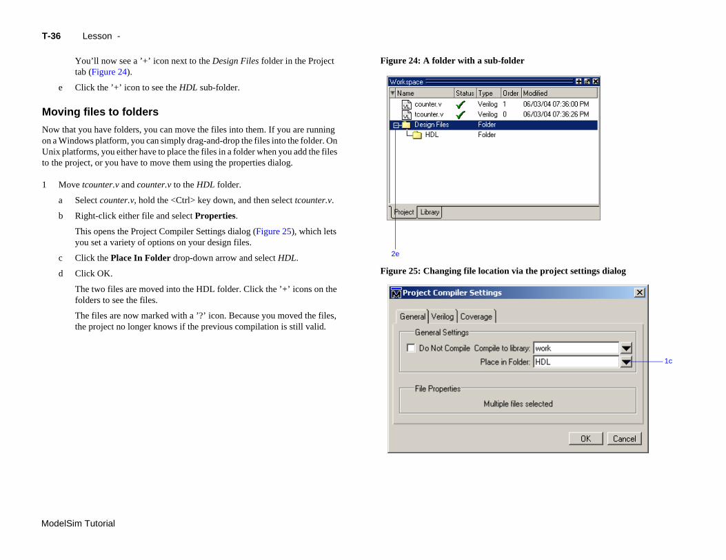
You’ll now see a ’+’ icon next to the Design Files folder in the Project tab (Figure 24).
e Click the ’+’ icon to see the HDL sub-folder.
oving files to folders
w that you have folders, you can move the files into them. If you are running a Windows platform, you can simply drag-and-drop the files into the folder. On ix platforms, you either have to place the files in a folder when you add the files the project, or you have to move them using the properties dialog.
Move tcounter.v and counter.v to the HDL folder.
a Select counter.v, hold the <Ctrl> key down, and then select tcounter.v.
b Right-click either file and select Properties.
This opens the Project Compiler Settings dialog (Figure 25), which lets you set a variety of options on your design files.
c Click the Place In Folder drop-down arrow and select HDL.
d Click OK.
The two files are moved into the HDL folder. Click the ’+’ icons on the folders to see the files.
The files are now marked with a ’?’ icon. Because you moved the files, the project no longer knows if the previous compilation is still valid.
Figure 24: A folder with a sub-f
Figure 25: Changing file locatio
2e
Simulation Configurations T-37
ModelSim Tutorial
S
A ForesyoSi"cthewi
1
The Project tab now shows a Simulation Configuration named counter
2
iguration dialog
uration in the Project tab
1b
1c
1e
1f
1d
(Figure 27).
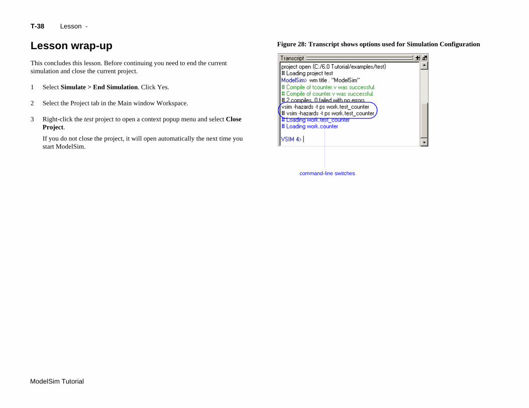
Load the Simulation Configuration.
a Double-click the counter Simulation Configuration in the Project tab.
In the Transcript pane of the Main window, the vsim (the ModelSim simulator) invocation shows the -hazards and -t ps switches (Figure 28). These are the command-line equivalents of the options you specified in the Simulate dialog.
imulation Configurations
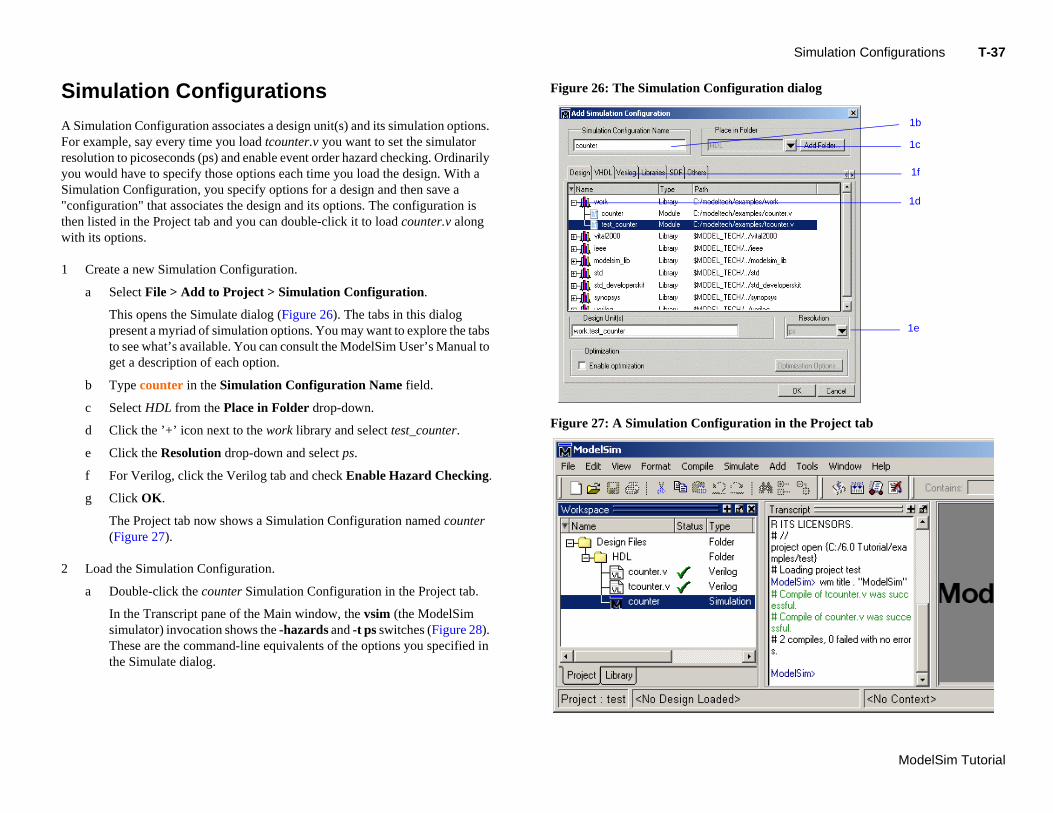
Simulation Configuration associates a design unit(s) and its simulation options. r example, say every time you load tcounter.v you want to set the simulator olution to picoseconds (ps) and enable event order hazard checking. Ordinarily u would have to specify those options each time you load the design. With a mulation Configuration, you specify options for a design and then save a onfiguration" that associates the design and its options. The configuration is n listed in the Project tab and you can double-click it to load counter.v along th its options.
Create a new Simulation Configuration.
a Select File > Add to Project > Simulation Configuration.
This opens the Simulate dialog (Figure 26). The tabs in this dialog present a myriad of simulation options. You may want to explore the tabs to see what’s available. You can consult the ModelSim User’s Manual to get a description of each option.
b Type counter in the Simulation Configuration Name field.
c Select HDL from the Place in Folder drop-down.
d Click the ’+’ icon next to the work library and select test_counter.
e Click the Resolution drop-down and select ps.
f For Verilog, click the Verilog tab and check Enable Hazard Checking.
g Click OK.
Figure 26: The Simulation Conf
Figure 27: A Simulation Config
T-
Mo
L
Thsim
1
2
3
tions used for Simulation Configuration
delSim Tutorial
38 Lesson -
esson wrap-up
is concludes this lesson. Before continuing you need to end the current ulation and close the current project.
Select Simulate > End Simulation. Click Yes.
Select the Project tab in the Main window Workspace.
Right-click the test project to open a context popup menu and select Close Project.
If you do not close the project, it will open automatically the next time you start ModelSim.
Figure 28: Transcript shows op
command-line switches
ModelSim Tutorial
T-39
Lesson 4 - Working with multiple libraries
Topics
The following topics are covered in this lesson:
Introduction . . . . . . . . . . . . . . . . . . . . . . . . . T-40Related reading . . . . . . . . . . . . . . . . . . . . . . . T-40
Creating the resource library . . . . . . . . . . . . . . . . . . . . . T-41
Creating the project . . . . . . . . . . . . . . . . . . . . . . . T-43
Linking to the resource library . . . . . . . . . . . . . . . . . . . . T-44
Pe
Le
rmanently mapping resource libraries . . . . . . . . . . . . . . . . . . T-47
sson wrap-up . . . . . . . . . . . . . . . . . . . . . . . . T-48
T-
Mo
In
InLeorpa
YodeFisim
D
Thas
Ve
VH
Thha
R
M
delSim Tutorial
40 Lesson -
troduction
this lesson you will practice working with multiple libraries. As discussed in sson 1 - ModelSim conceptual overview, you might have multiple libraries to ganize your design, to access IP from a third-party source, or to share common rts between simulations.
u will start the lesson by creating a resource library that contains the counter sign unit. Next, you will create a project and compile the testbench into it. nally, you will link to the library containing the counter and then run the
ulation.
esign files for this lesson
e sample design for this lesson is a simple 8-bit, binary up-counter with an sociated testbench. The pathnames are as follows:
rilog – <install_dir>/modeltech/examples/counter.v and tcounter.v
DL – <install_dir>/modeltech/examples/counter.vhd and tcounter.vhd
is lesson uses the Verilog files tcounter.v and counter.v in the examples. If you ve a VHDL license, use tcounter.vhd and counter.vhd instead.
elated reading
odelSim User’s Manual, 3 - Design libraries (UM-45)
Creating the resource library T-41
ModelSim Tutorial
C
1
2
3
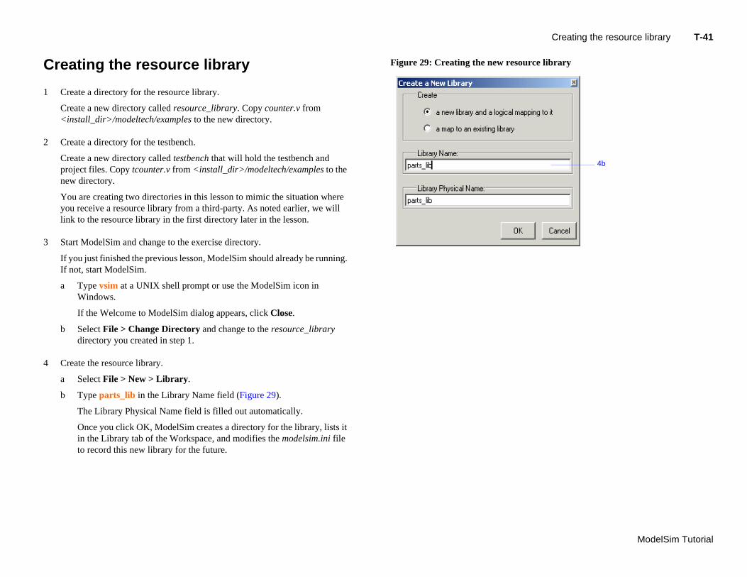
4 Create the resource library.
ource library
4b
a Select File > New > Library.
b Type parts_lib in the Library Name field (Figure 29).
The Library Physical Name field is filled out automatically.
Once you click OK, ModelSim creates a directory for the library, lists it in the Library tab of the Workspace, and modifies the modelsim.ini file to record this new library for the future.
reating the resource library
Create a directory for the resource library.
Create a new directory called resource_library. Copy counter.v from <install_dir>/modeltech/examples to the new directory.
Create a directory for the testbench.
Create a new directory called testbench that will hold the testbench and project files. Copy tcounter.v from <install_dir>/modeltech/examples to the new directory.
You are creating two directories in this lesson to mimic the situation where you receive a resource library from a third-party. As noted earlier, we will link to the resource library in the first directory later in the lesson.
Start ModelSim and change to the exercise directory.
If you just finished the previous lesson, ModelSim should already be running. If not, start ModelSim.
a Type vsim at a UNIX shell prompt or use the ModelSim icon in Windows.
If the Welcome to ModelSim dialog appears, click Close.
b Select File > Change Directory and change to the resource_library directory you created in step 1.
Figure 29: Creating the new res
T-
Mo
5
6
esource library
5b
5c
delSim Tutorial
42 Lesson -
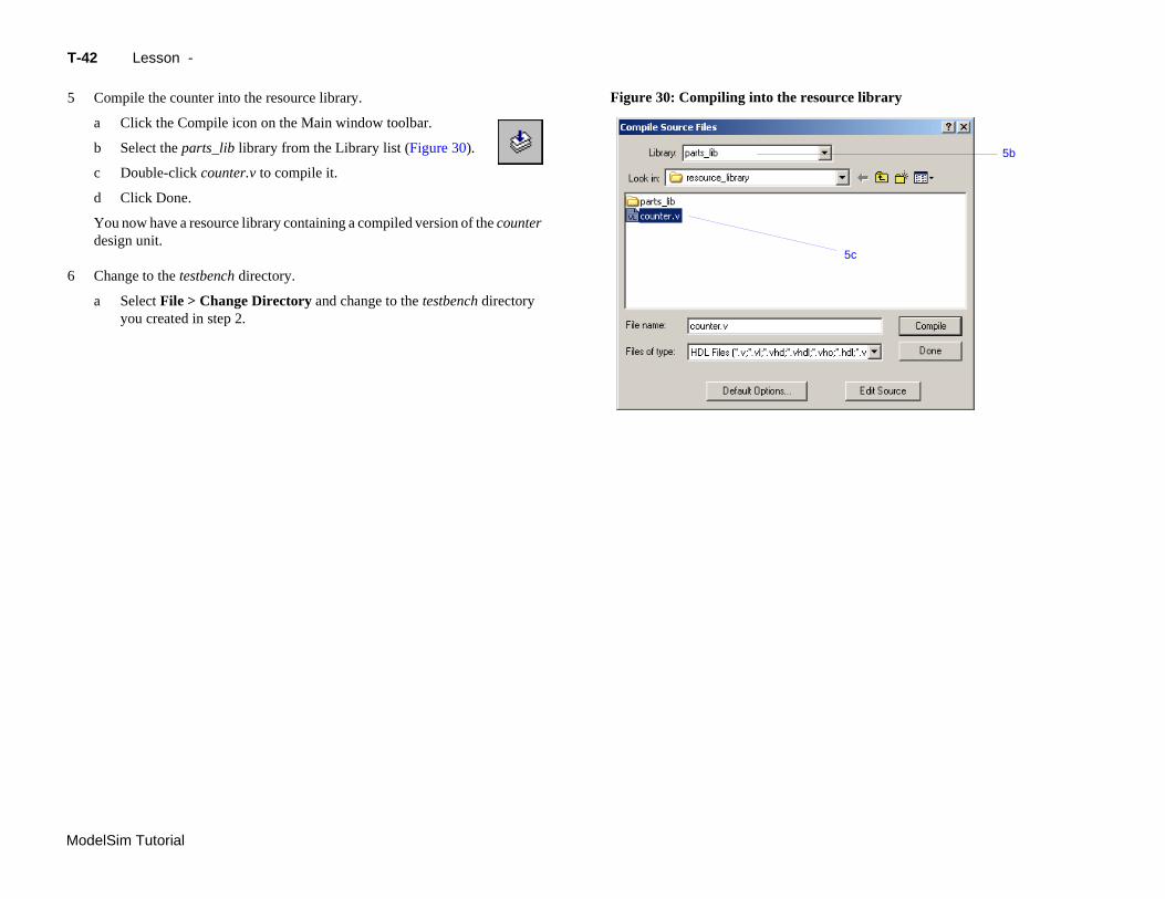
Compile the counter into the resource library.
a Click the Compile icon on the Main window toolbar.
b Select the parts_lib library from the Library list (Figure 30).
c Double-click counter.v to compile it.
d Click Done.
You now have a resource library containing a compiled version of the counter design unit.
Change to the testbench directory.
a Select File > Change Directory and change to the testbench directory you created in step 2.
Figure 30: Compiling into the r
Creating the project T-43
ModelSim Tutorial
C
No
1
2
3
reating the project
w you will create a project that contains tcounter.v, the counter’s testbench.
Create the project.
a Select File > New > Project.
b Type counter in the Project Name field.
c Click OK.
d If a dialog appears asking about which modelsim.ini file to use, click Use Default Ini.
Add the testbench to the project.
a Click Add Existing File in the Add items to the Project dialog.
b Click the Browse button and select tcounter.v.
c Click Open and then OK.
d Click Close to dismiss the Add items to the Project dialog.
The tcounter.v file is listed in the Project tab of the Main window.
Compile the testbench.
a Right-click tcounter.v and select Compile > Compile Selected.
T-
Mo
L
Toeaha
M
Ve
1
VH
1
ror reported in the Main window
rning reported in Main window
delSim Tutorial
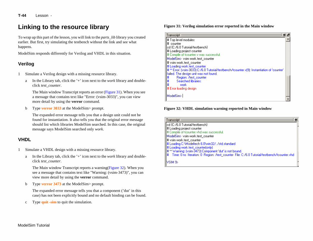
a In the Library tab, click the ’+’ icon next to the work library and double-click test_counter.
The Main window Transcript reports a warning(Figure 32). When you see a message that contains text like "Warning: (vsim-3473)", you can view more detail by using the verror command.
b Type verror 3473 at the ModelSim> prompt.
The expanded error message tells you that a component (’dut’ in this case) has not been explicitly bound and no default binding can be found.
c Type quit -sim to quit the simulation.
44 Lesson -
inking to the resource library
wrap up this part of the lesson, you will link to the parts_lib library you created rlier. But first, try simulating the testbench without the link and see what ppens.
odelSim responds differently for Verilog and VHDL in this situation.
rilog
Simulate a Verilog design with a missing resource library.
a In the Library tab, click the ’+’ icon next to the work library and double-click test_counter.
The Main window Transcript reports an error (Figure 31). When you see a message that contains text like "Error: (vsim-3033)", you can view more detail by using the verror command.
b Type verror 3033 at the ModelSim> prompt.
The expanded error message tells you that a design unit could not be found for instantiation. It also tells you that the original error message should list which libraries ModelSim searched. In this case, the original message says ModelSim searched only work.
DL
Simulate a VHDL design with a missing resource library.
Figure 31: Verilog simulation er
Figure 32: VHDL simulation wa
Linking to the resource library T-45
ModelSim Tutorial
ThIf us
Li
Lithe
1
brary in the Simulate dialog
e process for linking to a resource library differs between Verilog and VHDL. you are using Verilog, follow the steps in "Linking in Verilog" (T-45). If you are ing VHDL, follow the steps in "Linking in VHDL" (T-46) one page later.nking in Verilog
nking in Verilog requires that you specify a "search library" when you invoke simulator.
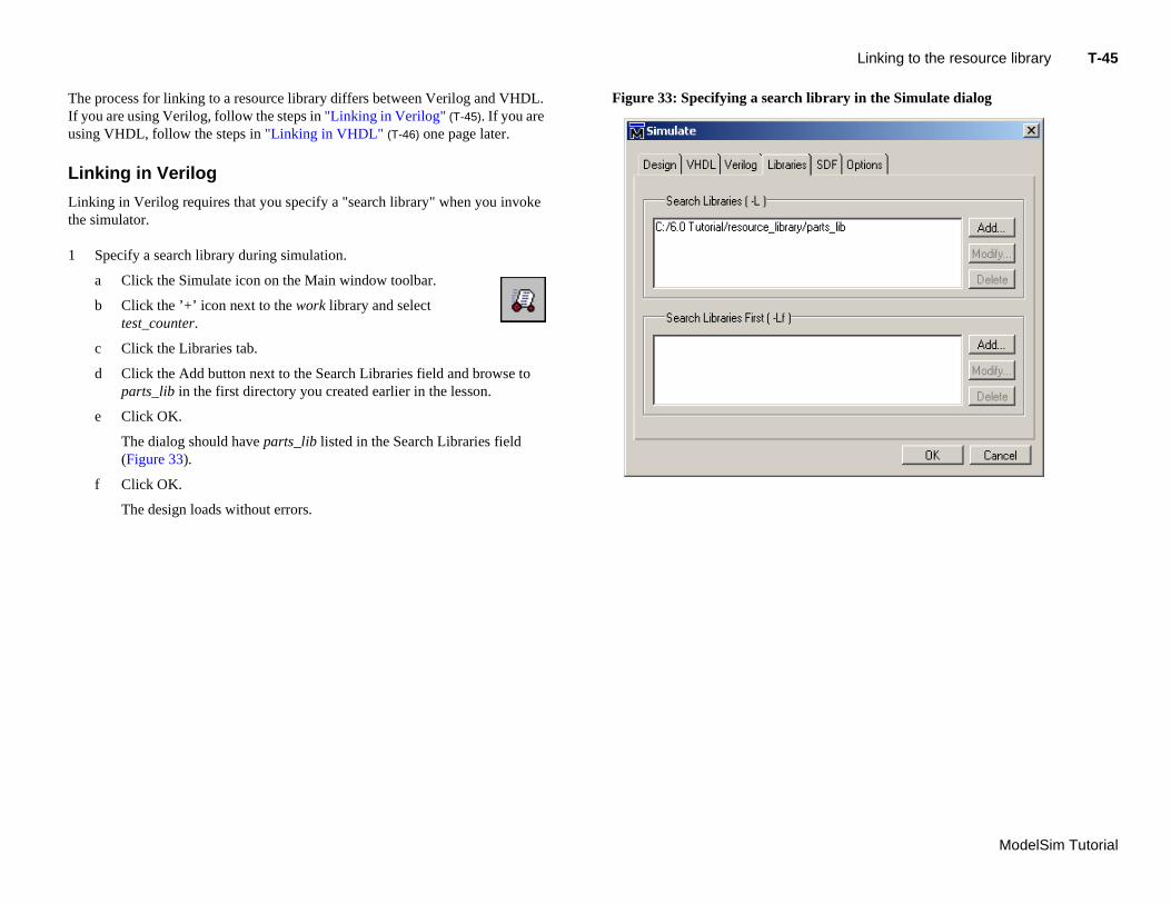
Specify a search library during simulation.
a Click the Simulate icon on the Main window toolbar.
b Click the ’+’ icon next to the work library and select test_counter.
c Click the Libraries tab.
d Click the Add button next to the Search Libraries field and browse to parts_lib in the first directory you created earlier in the lesson.
e Click OK.
The dialog should have parts_lib listed in the Search Libraries field (Figure 33).
f Click OK.
The design loads without errors.
Figure 33: Specifying a search li
T-
Mo
Li
Toph
1
2
3
_lib library
nd USE statements to the testbench
delSim Tutorial
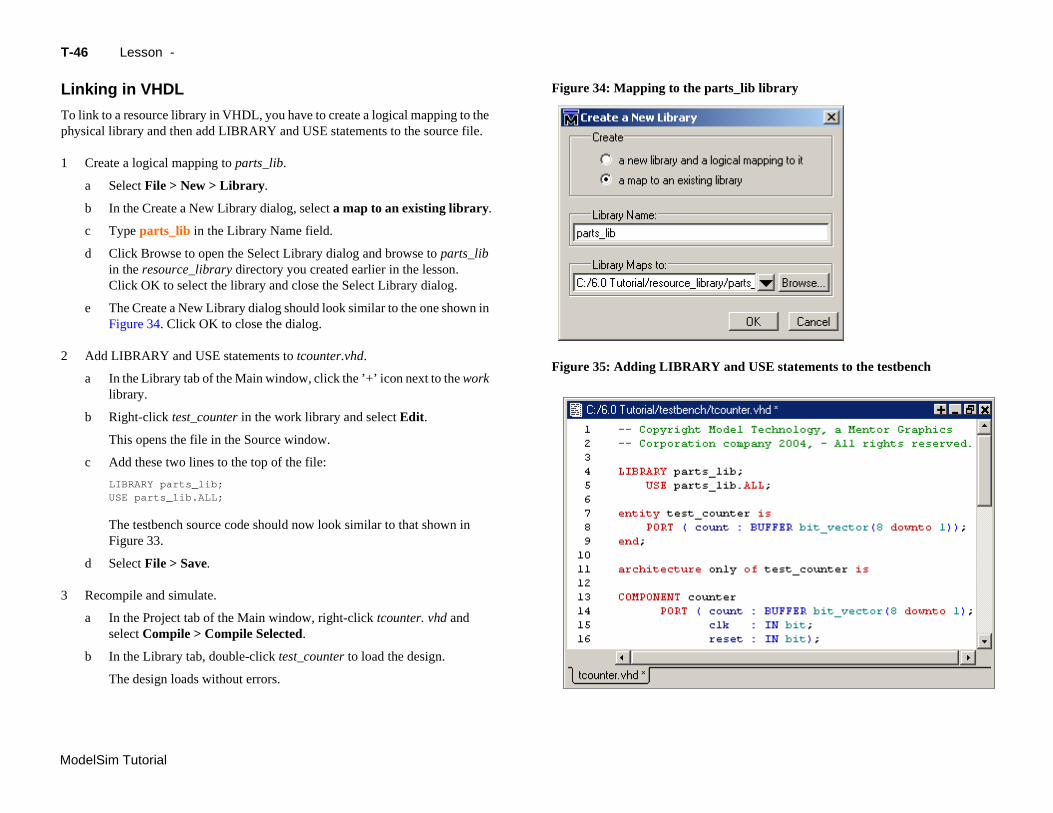
The testbench source code should now look similar to that shown in Figure 33.
d Select File > Save.
Recompile and simulate.
a In the Project tab of the Main window, right-click tcounter. vhd and select Compile > Compile Selected.
b In the Library tab, double-click test_counter to load the design.
The design loads without errors.
46 Lesson -
nking in VHDL
link to a resource library in VHDL, you have to create a logical mapping to the ysical library and then add LIBRARY and USE statements to the source file.
Create a logical mapping to parts_lib.
a Select File > New > Library.
b In the Create a New Library dialog, select a map to an existing library.
c Type parts_lib in the Library Name field.
d Click Browse to open the Select Library dialog and browse to parts_lib in the resource_library directory you created earlier in the lesson. Click OK to select the library and close the Select Library dialog.
e The Create a New Library dialog should look similar to the one shown in Figure 34. Click OK to close the dialog.
Add LIBRARY and USE statements to tcounter.vhd.
a In the Library tab of the Main window, click the ’+’ icon next to the work library.
b Right-click test_counter in the work library and select Edit.
This opens the file in the Source window.
c Add these two lines to the top of the file:
LIBRARY parts_lib;USE parts_lib.ALL;
Figure 34: Mapping to the parts
Figure 35: Adding LIBRARY a
manently mapping resource libraries T-47
ModelSim Tutorial
P
If mamapr
1
2
3
4
5
6
Per
ermanently mapping resource libraries
you reference particular resource libraries in every project or simulation, you y want to permanently map the libraries. Doing this requires that you edit the ster modelsim.ini file in the installation directory. Though you won’t actually
actice it in this tutorial, here are the steps for editing the file:
Locate the modelsim.ini file in the ModelSim installation directory (<install_dir>/modeltech/modelsim.ini).
IMPORTANT - Make a backup copy of the file.
Change the file attributes of modelsim.ini so it is no longer "read-only."
Open the file and enter your library mappings in the [Library] section. For example:
parts_lib = C:/libraries/parts_lib
Save the file.
Change the file attributes so the file is "read-only" again.
T-
Mo
L
Thsim
1
2
3
delSim Tutorial
48 Lesson -
esson wrap-up
is concludes this lesson. Before continuing we need to end the current ulation and close the project.
Select Simulate > End Simulation. Click Yes.
Select the Project tab of the Main window Workspace.
Select File > Close. Click OK.
ModelSim Tutorial
T-49
Lesson 5 - Viewing simulations in the Wave window
Topics
The following topics are covered in this lesson:
Introduction . . . . . . . . . . . . . . . . . . . . . . . . . T-50Related reading . . . . . . . . . . . . . . . . . . . . . . . T-50
Loading a design . . . . . . . . . . . . . . . . . . . . . . . . T-51
Adding objects to the Wave window. . . . . . . . . . . . . . . . . . . T-52
Using cursors in the Wave window . . . . . . . . . . . . . . . . . . . T-54
Sa
Le
Working with a single cursor . . . . . . . . . . . . . . . . . . . T-54Working with multiple cursors . . . . . . . . . . . . . . . . . . . T-55
ving the window format . . . . . . . . . . . . . . . . . . . . . T-57
sson wrap-up . . . . . . . . . . . . . . . . . . . . . . . . T-58
T-
Mo
In
Thwa
Thwiba
R
M
M12
nd its many panes
waveform
cursore
delSim Tutorial
50 Lesson -
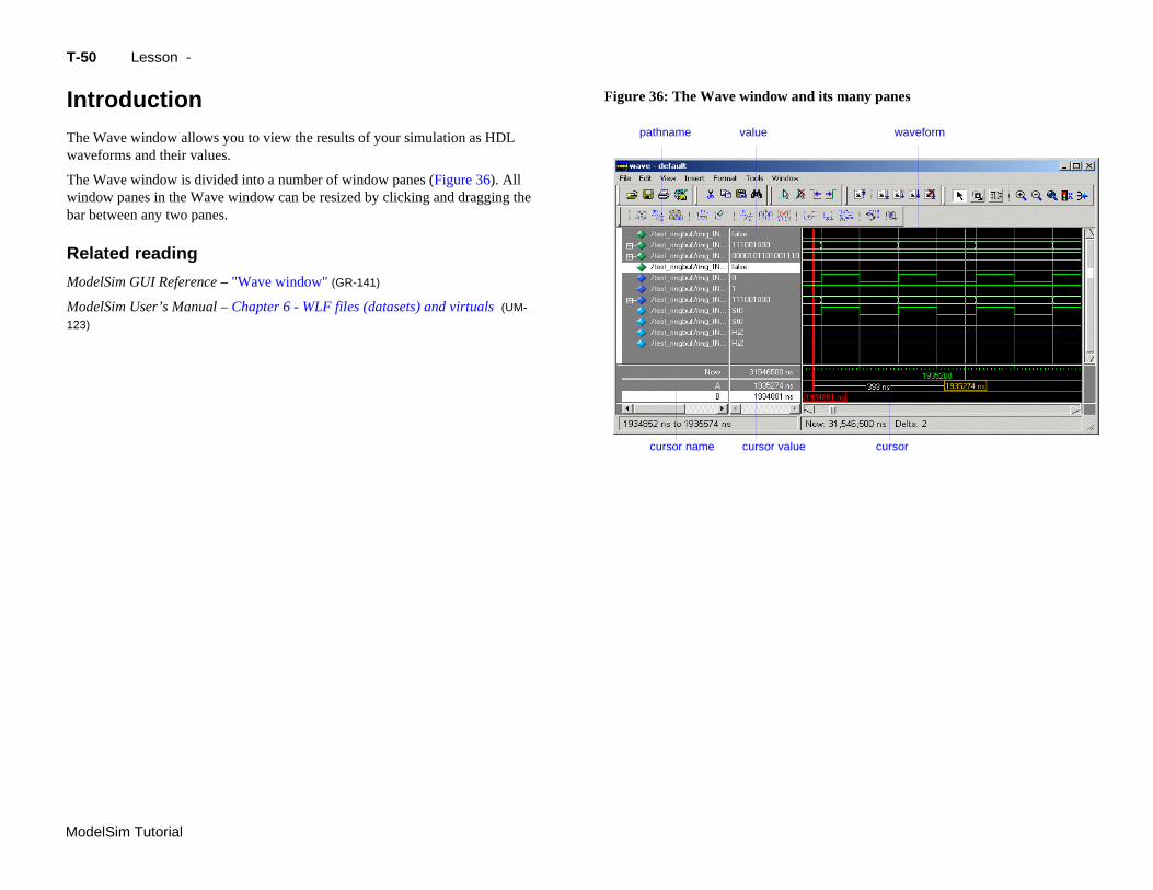
troduction
e Wave window allows you to view the results of your simulation as HDL veforms and their values.
e Wave window is divided into a number of window panes (Figure 36). All ndow panes in the Wave window can be resized by clicking and dragging the r between any two panes.
elated reading
odelSim GUI Reference – "Wave window" (GR-141)
odelSim User’s Manual – Chapter 6 - WLF files (datasets) and virtuals (UM-
3)
Figure 36: The Wave window a
pathname value
cursor name cursor valu
Loading a design T-51
ModelSim Tutorial
L
FoLe
1
2
oading a design
r the examples in this lesson, we have used the design simulated in Chapter sson 2 - Basic simulation.
If you just finished the previous lesson, ModelSim should already be running. If not, start ModelSim.
a Type vsim at a UNIX shell prompt or use the ModelSim icon in Windows.
If the Welcome to ModelSim dialog appears, click Close.
Load the design.
a Select File > Change Directory and open the directory you created in Lesson 2.
The work library should already exist.
b Click the ’+’ icon next to the work library and double-click test_counter.
ModelSim loads the design and adds sim and Files tabs to the Workspace.
T-
Mo
A
Mex
1
2
3
a Type add wave * at the VSIM> prompt.
delSim Tutorial
ModelSim adds all objects from the current region.
b Run the simulation for awhile so you can see waveforms.
52 Lesson -
dding objects to the Wave window
odelSim offers several methods for adding objects to the Wave window. In this ercise, you will try different methods.
Add objects from the Objects pane.
a Select an item in the Objects pane of the Main window, and then select Add to Wave > Signals in Region.
ModelSim adds several signals to the Wave window.
b In the Wave window, select Edit > Select All and then Edit > Delete.
This deletes all objects in the window.
Add objects using drag-and-drop.
You can drag an object to the Wave window from many other windows and panes (e.g., Workspace, Objects, and Locals).
a Drag an instance from the sim tab of the Main window to the Wave window.
ModelSim adds the objects for that instance to the Wave window.
b Drag a signal from the Objects pane to the Wave window.
c In the Wave window, select Edit > Select All and then Edit > Delete.
Add objects using a command.
Zooming the waveform display T-53
ModelSim Tutorial
Z
Zonu
1
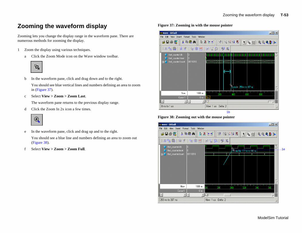
f Select View > Zoom > Zoom Full.
mouse pointer
mouse pointer1b
1e
ooming the waveform display
oming lets you change the display range in the waveform pane. There are merous methods for zooming the display.
Zoom the display using various techniques.
a Click the Zoom Mode icon on the Wave window toolbar.
b In the waveform pane, click and drag down and to the right.
You should see blue vertical lines and numbers defining an area to zoom in (Figure 37).
c Select View > Zoom > Zoom Last.
The waveform pane returns to the previous display range.
d Click the Zoom In 2x icon a few times.
e In the waveform pane, click and drag up and to the right.
You should see a blue line and numbers defining an area to zoom out (Figure 38).
Figure 37: Zooming in with the
Figure 38: Zooming out with the
T-
Mo
U
Cuthewa
Yoto
W
1
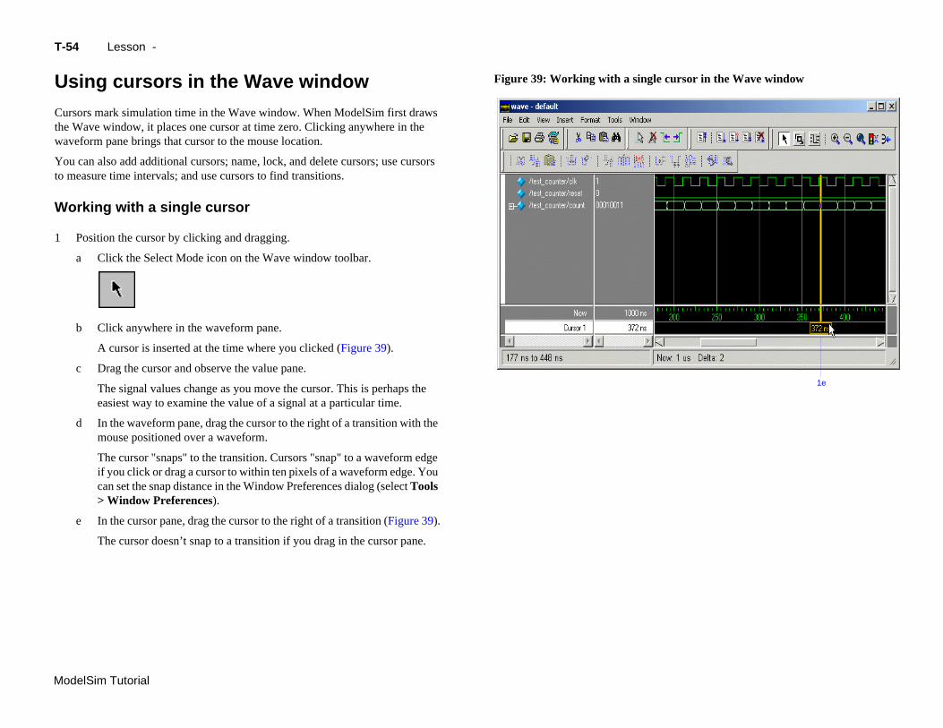
The cursor "snaps" to the transition. Cursors "snap" to a waveform edge
le cursor in the Wave window
1e
delSim Tutorial
if you click or drag a cursor to within ten pixels of a waveform edge. You can set the snap distance in the Window Preferences dialog (select Tools > Window Preferences).
e In the cursor pane, drag the cursor to the right of a transition (Figure 39).
The cursor doesn’t snap to a transition if you drag in the cursor pane.
54 Lesson -
sing cursors in the Wave window
rsors mark simulation time in the Wave window. When ModelSim first draws Wave window, it places one cursor at time zero. Clicking anywhere in the veform pane brings that cursor to the mouse location.
u can also add additional cursors; name, lock, and delete cursors; use cursors measure time intervals; and use cursors to find transitions.
orking with a single cursor
Position the cursor by clicking and dragging.
a Click the Select Mode icon on the Wave window toolbar.
b Click anywhere in the waveform pane.
A cursor is inserted at the time where you clicked (Figure 39).
c Drag the cursor and observe the value pane.
The signal values change as you move the cursor. This is perhaps the easiest way to examine the value of a signal at a particular time.
d In the waveform pane, drag the cursor to the right of a transition with the mouse positioned over a waveform.
Figure 39: Working with a sing
Using cursors in the Wave window T-55
ModelSim Tutorial
2
3
W
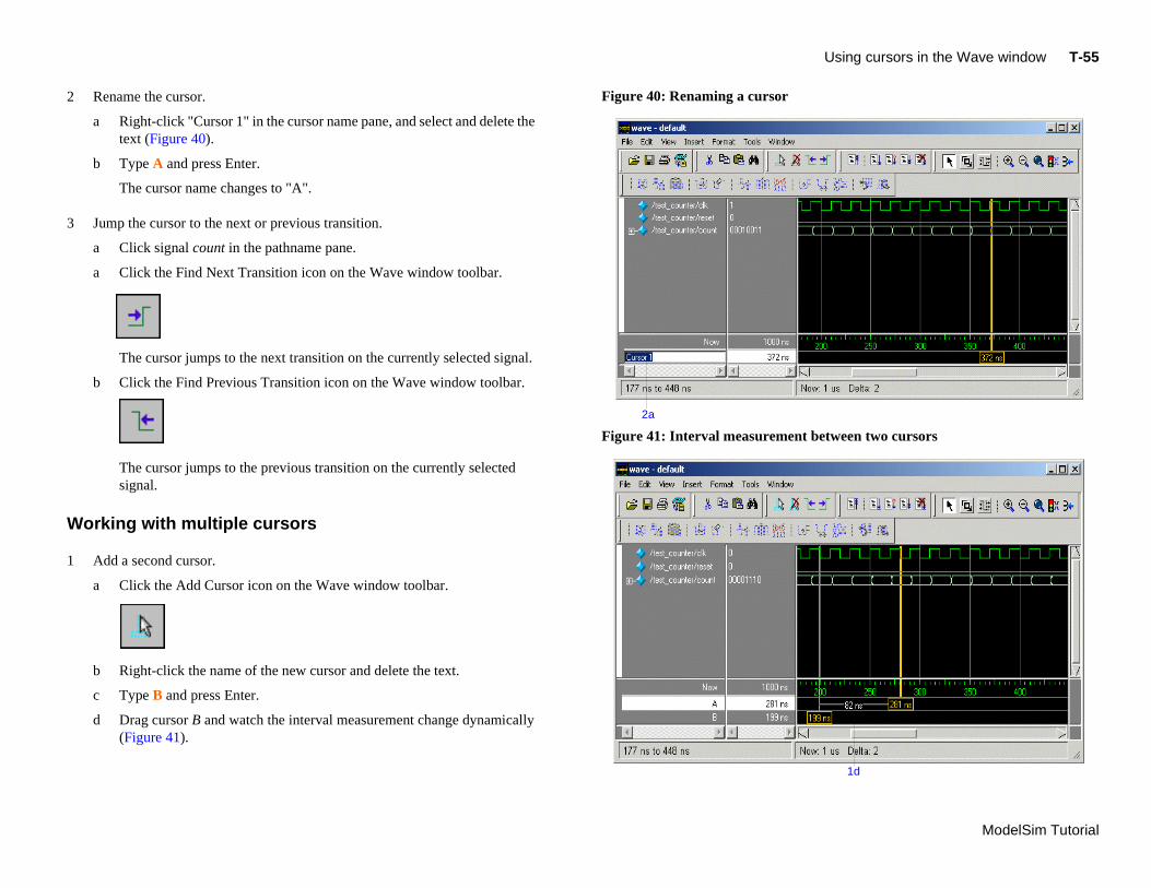
1 Add a second cursor.
t between two cursors
1d
a Click the Add Cursor icon on the Wave window toolbar.
b Right-click the name of the new cursor and delete the text.
c Type B and press Enter.
d Drag cursor B and watch the interval measurement change dynamically (Figure 41).
Rename the cursor.
a Right-click "Cursor 1" in the cursor name pane, and select and delete the text (Figure 40).
b Type A and press Enter.
The cursor name changes to "A".
Jump the cursor to the next or previous transition.
a Click signal count in the pathname pane.
a Click the Find Next Transition icon on the Wave window toolbar.
The cursor jumps to the next transition on the currently selected signal.
b Click the Find Previous Transition icon on the Wave window toolbar.
The cursor jumps to the previous transition on the currently selected signal.
orking with multiple cursors
Figure 40: Renaming a cursor
Figure 41: Interval measuremen
2a
T-
Mo
2
3
e Wave window
delSim Tutorial
56 Lesson -
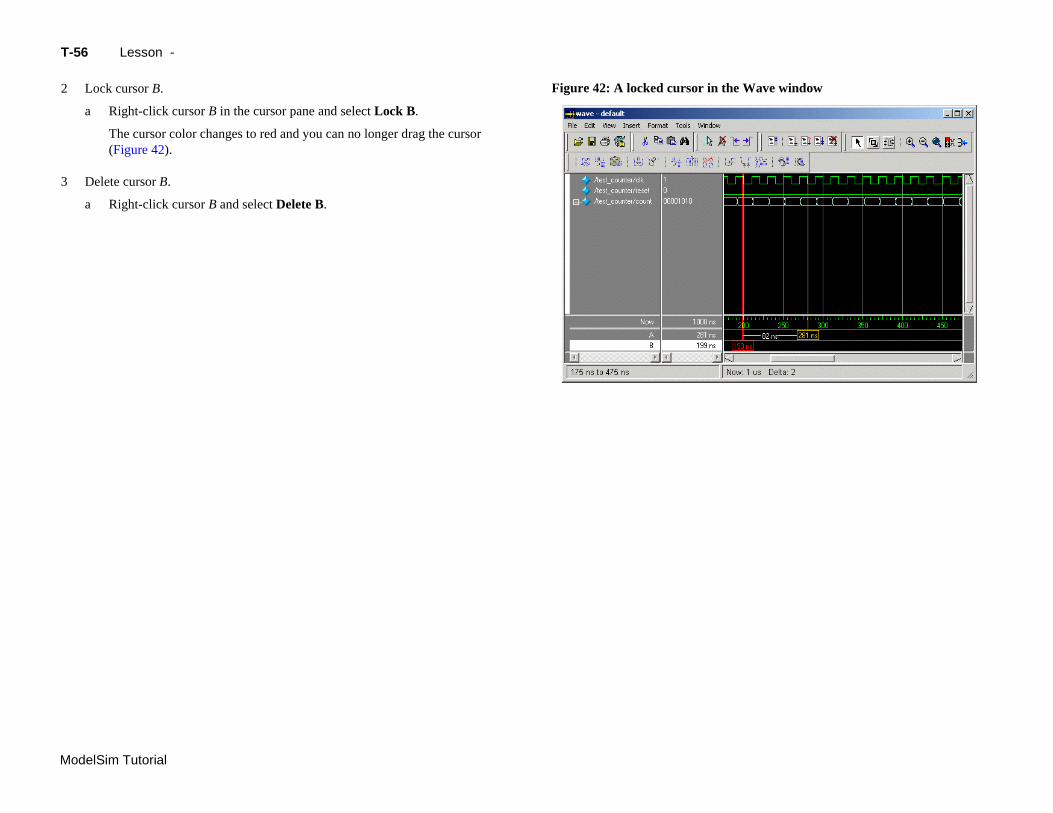
Lock cursor B.
a Right-click cursor B in the cursor pane and select Lock B.
The cursor color changes to red and you can no longer drag the cursor (Figure 42).
Delete cursor B.
a Right-click cursor B and select Delete B.
Figure 42: A locked cursor in th
Saving the window format T-57
ModelSim Tutorial
S
If sigFopras
Fosim
1
2
aving the window format
you close the Wave window, any configurations you made to the window (e.g., nals added, cursors set, etc.) are discarded. However, you can use the Save rmat command to capture the current Wave window display and signal eferences to a DO file. You open the DO file later to recreate the Wave window it appeared when the file was created.
rmat files are design-specific; use them only with the design you were ulating when they were created.
Save a format file.
a Select File > Save > Format.
b Leave the file name set to wave.do and click Save.
c Close the Wave window.
Load a format file.
a In the Main window, select View > Debug Windows > Wave.
All signals and cursor(s) that you had set are gone.
b In the Wave window, select File > Open > Format.
c Select wave.do and click Open.
ModelSim restores the window to its previous state.
d Close the Wave window when you are finished by selecting File > Close.
T-
Mo
L
Thsim
1
delSim Tutorial
58 Lesson -
esson wrap-up
is concludes this lesson. Before continuing we need to end the current ulation.
Select Simulate > End Simulation. Click Yes.
ModelSim Tutorial
T-59
Lesson 6 - Viewing and initializing memories
Topics
The following topics are covered in this lesson:
Introduction . . . . . . . . . . . . . . . . . . . . . . . . . T-60Related reading . . . . . . . . . . . . . . . . . . . . . . . T-60
Compiling and loading the design . . . . . . . . . . . . . . . . . . . T-61
Viewing a memory . . . . . . . . . . . . . . . . . . . . . . . T-62Navigating within the memory . . . . . . . . . . . . . . . . . . . T-64
Sa
In
In
Le
ving memory contents to a file . . . . . . . . . . . . . . . . . . . T-66
itializing a memory . . . . . . . . . . . . . . . . . . . . . . T-67
teractive debugging commands . . . . . . . . . . . . . . . . . . . T-69
sson Wrap-up . . . . . . . . . . . . . . . . . . . . . . . . T-71
T-
Mo
In
InM
D
Thex
Ve
VH
Thlic
R
M
Mm
delSim Tutorial
60 Lesson -
troduction
this lesson you will learn how to view and initialize memories in ModelSim. odelSim defines and lists as memories any of the following:
• reg, wire, and std_logic arrays
• Integer arrays
• Single dimensional arrays of VHDL enumerated types other than std_logic
esign files for this lesson
e ModelSim installation comes with Verilog and VHDL versions of the ample design. The files are located in the following directories:
rilog – <install_dir>/modeltech/examples/memory/verilog
DL – <install_dir>/modeltech/examples/memory/vhdl
is lesson uses the Verilog version for the exercises. If you have a VHDL ense, use the VHDL version instead.
elated reading
odelSim GUI Reference – "Memory windows" (GR-109)
odelSim Command Reference – mem display (CR-101), mem load (CR-104), em save (CR-107), radix (CR-128) commands
Compiling and loading the design T-61
ModelSim Tutorial
C
1
2
3
4
VHDL:Type vcom -93 sp_syn_ram.vhd dp_syn_ram.vhd ram_tb.vhd at the ModelSim> prompt.
Type set NumericStdNoWarnings 1 at the ModelSim> prompt to suppress NumericStd warnings encountered during simulation.
Load the design.
a On the Library tab of the Main window Workspace, click the "+" icon next to the work library.
b Double-click the ram_tb design unit to load the design.
ompiling and loading the design
Create a new directory and copy the tutorial files into it.
Start by creating a new directory for this exercise (in case other users will be working with these lessons). Create the directory and copy all files from <install_dir>/examples/memory/verilog to the new directory.
If you have a VHDL license, copy the files in <install_dir>/examples/memory/vhdl instead.
Start ModelSim and change to the exercise directory.
If you just finished the previous lesson, ModelSim should already be running. If not, start ModelSim.
a Type vsim at a UNIX shell prompt or use the ModelSim icon in Windows.
If the Welcome to ModelSim dialog appears, click Close.
b Select File > Change Directory and change to the directory you created in step 1.
Create the working library and compile the design.
a Type vlib work at the ModelSim> prompt.
b Verilog: Type vlog sp_syn_ram.v dp_syn_ram.v ram_tb.v at the ModelSim> prompt.
T-
Mo
V
M
1
es tab in the Main window workspace
DI pane shows instance
delSim Tutorial
62 Lesson -
iewing a memory
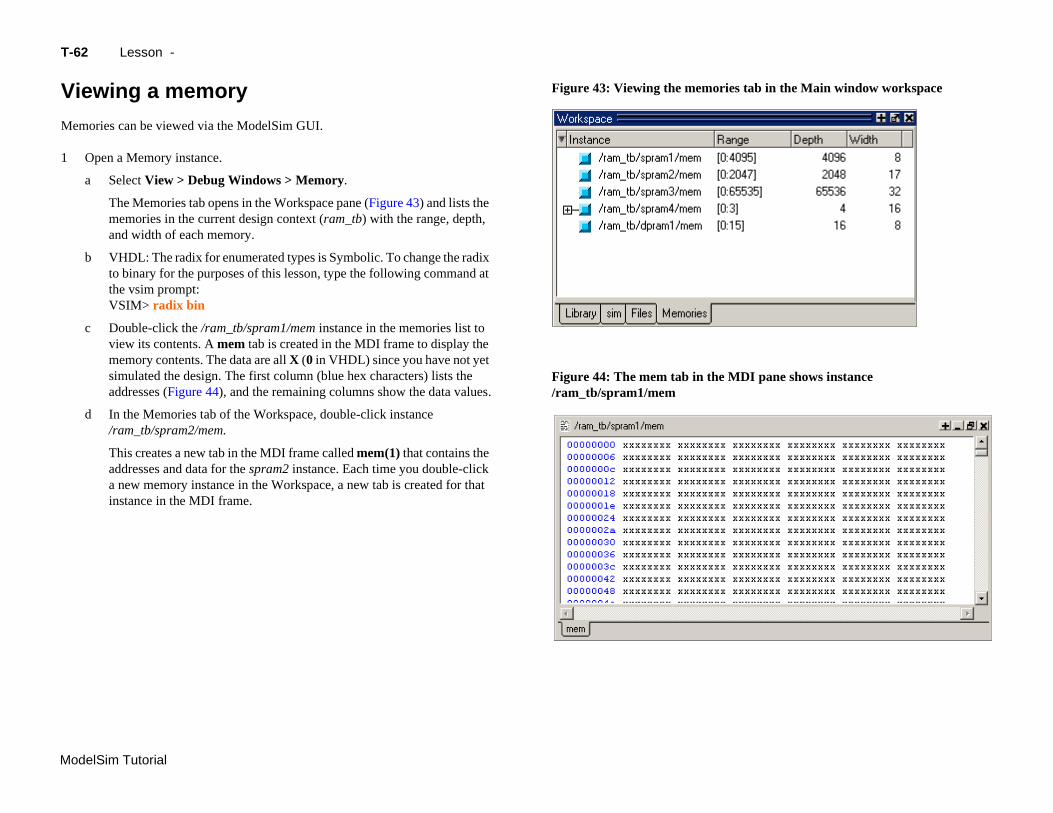
emories can be viewed via the ModelSim GUI.
Open a Memory instance.
a Select View > Debug Windows > Memory.
The Memories tab opens in the Workspace pane (Figure 43) and lists the memories in the current design context (ram_tb) with the range, depth, and width of each memory.
b VHDL: The radix for enumerated types is Symbolic. To change the radix to binary for the purposes of this lesson, type the following command at the vsim prompt:VSIM> radix bin
c Double-click the /ram_tb/spram1/mem instance in the memories list to view its contents. A mem tab is created in the MDI frame to display the memory contents. The data are all X (0 in VHDL) since you have not yet simulated the design. The first column (blue hex characters) lists the addresses (Figure 44), and the remaining columns show the data values.
d In the Memories tab of the Workspace, double-click instance /ram_tb/spram2/mem.
This creates a new tab in the MDI frame called mem(1) that contains the addresses and data for the spram2 instance. Each time you double-click a new memory instance in the Workspace, a new tab is created for that instance in the MDI frame.
Figure 43: Viewing the memori
Figure 44: The mem tab in the M/ram_tb/spram1/mem
Viewing a memory T-63
ModelSim Tutorial
2
3
ates with simulation
s radix
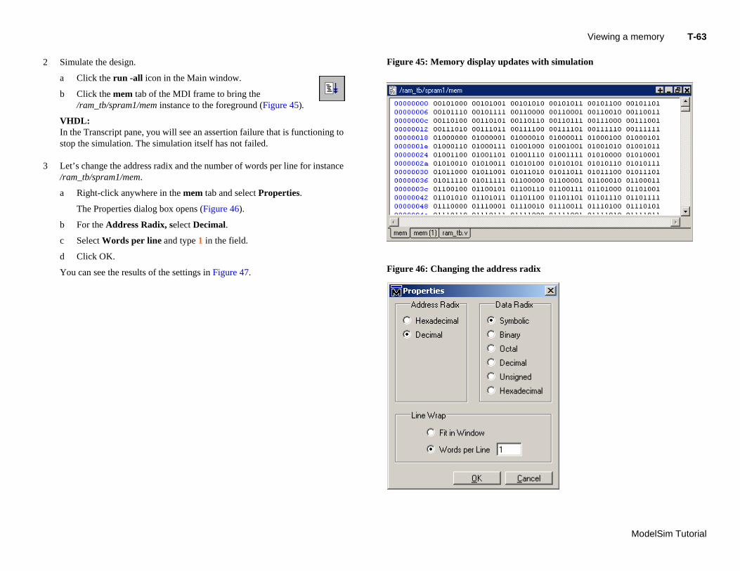
Simulate the design.
a Click the run -all icon in the Main window.
b Click the mem tab of the MDI frame to bring the /ram_tb/spram1/mem instance to the foreground (Figure 45).
VHDL: In the Transcript pane, you will see an assertion failure that is functioning to stop the simulation. The simulation itself has not failed.
Let’s change the address radix and the number of words per line for instance /ram_tb/spram1/mem.
a Right-click anywhere in the mem tab and select Properties.
The Properties dialog box opens (Figure 46).
b For the Address Radix, select Decimal.
c Select Words per line and type 1 in the field.
d Click OK.
You can see the results of the settings in Figure 47.
Figure 45: Memory display upd
Figure 46: Changing the addres
T-
Mo
N
Yopa
1
w address radix and line length
delSim Tutorial
64 Lesson -
avigating within the memory
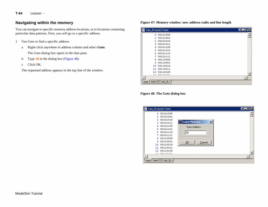
u can navigate to specific memory address locations, or to locations containing rticular data patterns. First, you will go to a specific address.
Use Goto to find a specific address.
a Right-click anywhere in address column and select Goto.
The Goto dialog box opens in the data pane.
b Type 30 in the dialog box (Figure 48).
c Click OK.
The requested address appears in the top line of the window.
Figure 47: Memory window: ne
Figure 48: The Goto dialog box
Viewing a memory T-65
ModelSim Tutorial
2
3
ctly
r data value
2b
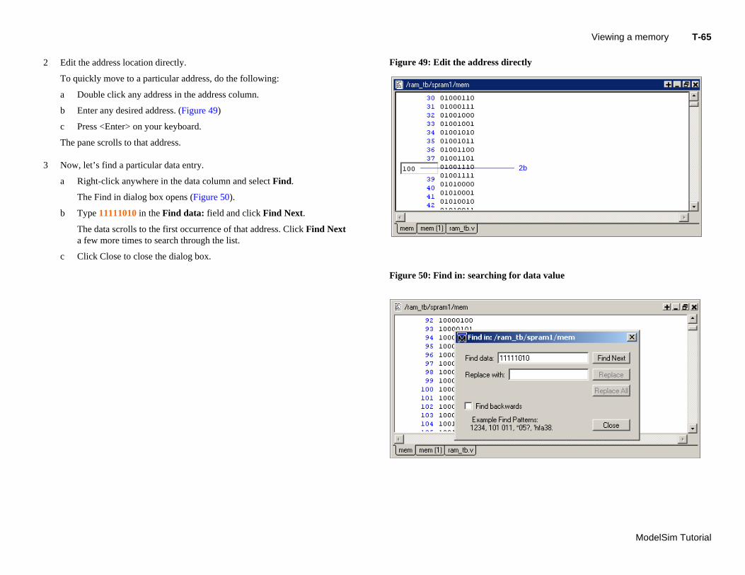
Edit the address location directly.
To quickly move to a particular address, do the following:
a Double click any address in the address column.
b Enter any desired address. (Figure 49)
c Press <Enter> on your keyboard.
The pane scrolls to that address.
Now, let’s find a particular data entry.
a Right-click anywhere in the data column and select Find.
The Find in dialog box opens (Figure 50).
b Type 11111010 in the Find data: field and click Find Next.
The data scrolls to the first occurrence of that address. Click Find Next a few more times to search through the list.
c Click Close to close the dialog box.
Figure 49: Edit the address dire
Figure 50: Find in: searching fo
T-
Mo
S
Yosim
1
Madme
2
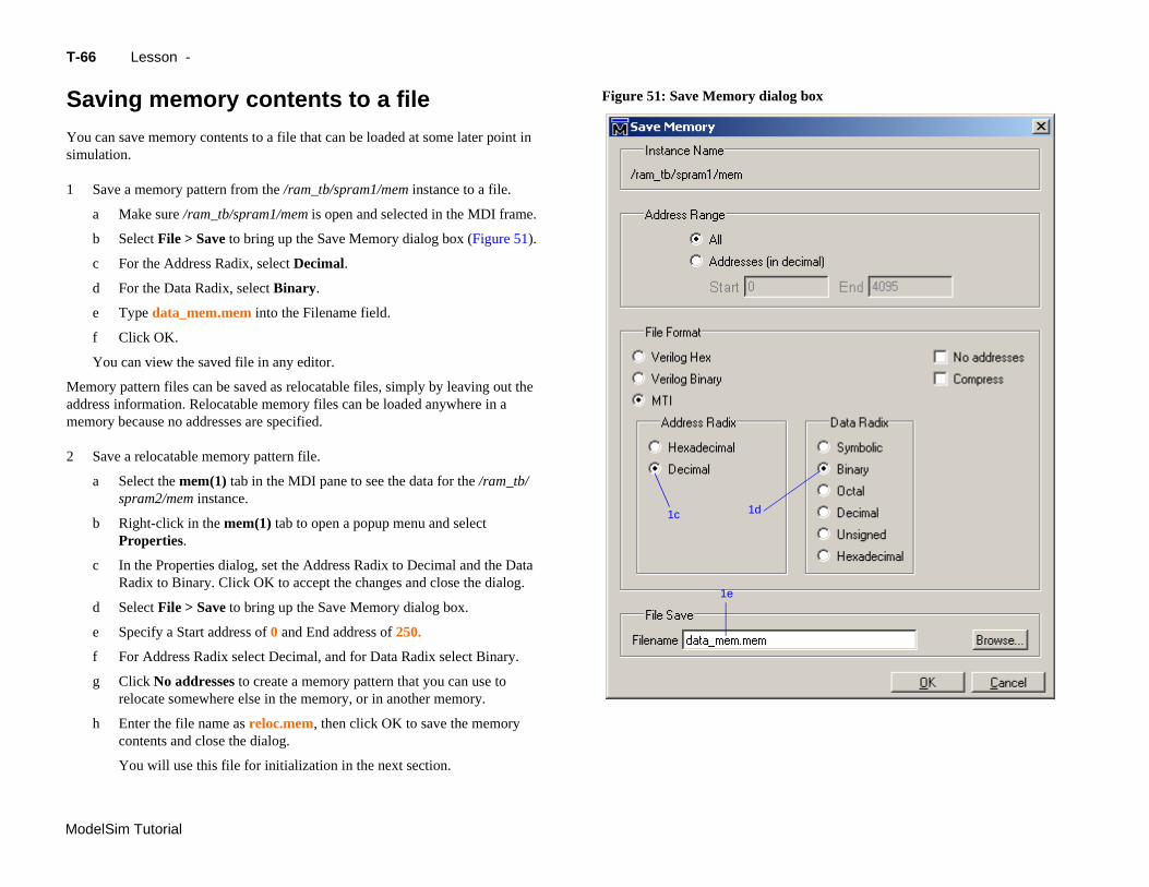
c In the Properties dialog, set the Address Radix to Decimal and the Data
box
delSim Tutorial
Radix to Binary. Click OK to accept the changes and close the dialog.
d Select File > Save to bring up the Save Memory dialog box.
e Specify a Start address of 0 and End address of 250.
f For Address Radix select Decimal, and for Data Radix select Binary.
g Click No addresses to create a memory pattern that you can use to relocate somewhere else in the memory, or in another memory.
h Enter the file name as reloc.mem, then click OK to save the memory contents and close the dialog.
You will use this file for initialization in the next section.
1e
66 Lesson -
aving memory contents to a file
u can save memory contents to a file that can be loaded at some later point in ulation.
Save a memory pattern from the /ram_tb/spram1/mem instance to a file.
a Make sure /ram_tb/spram1/mem is open and selected in the MDI frame.
b Select File > Save to bring up the Save Memory dialog box (Figure 51).
c For the Address Radix, select Decimal.
d For the Data Radix, select Binary.
e Type data_mem.mem into the Filename field.
f Click OK.
You can view the saved file in any editor.
emory pattern files can be saved as relocatable files, simply by leaving out the dress information. Relocatable memory files can be loaded anywhere in a mory because no addresses are specified.
Save a relocatable memory pattern file.
a Select the mem(1) tab in the MDI pane to see the data for the /ram_tb/spram2/mem instance.
b Right-click in the mem(1) tab to open a popup menu and select Properties.
Figure 51: Save Memory dialog
1c 1d
Initializing a memory T-67
ModelSim Tutorial
In
Infro
Fipr
1
2
box
om file and fill pattern
2b
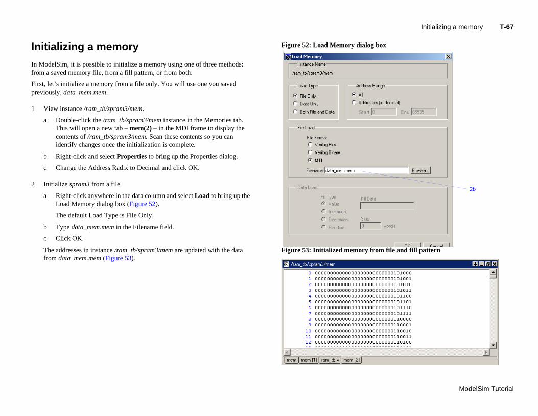
itializing a memory
ModelSim, it is possible to initialize a memory using one of three methods: m a saved memory file, from a fill pattern, or from both.
rst, let’s initialize a memory from a file only. You will use one you saved eviously, data_mem.mem.
View instance /ram_tb/spram3/mem.
a Double-click the /ram_tb/spram3/mem instance in the Memories tab. This will open a new tab – mem(2) – in the MDI frame to display the contents of /ram_tb/spram3/mem. Scan these contents so you can identify changes once the initialization is complete.
b Right-click and select Properties to bring up the Properties dialog.
c Change the Address Radix to Decimal and click OK.
Initialize spram3 from a file.
a Right-click anywhere in the data column and select Load to bring up the Load Memory dialog box (Figure 52).
The default Load Type is File Only.
b Type data_mem.mem in the Filename field.
c Click OK.
The addresses in instance /ram_tb/spram3/mem are updated with the data from data_mem.mem (Figure 53).
Figure 52: Load Memory dialog
Figure 53: Initialized memory fr
T-
Mo
Inpaprad
3
Yoyo
Novie
4
e memory file
n memory instance
3c
3f
3d
3e
delSim Tutorial
w, before you leave this section, go ahead and clear the instances already being wed.
Right-click in the mem(2) tab and select Close All.
68 Lesson -
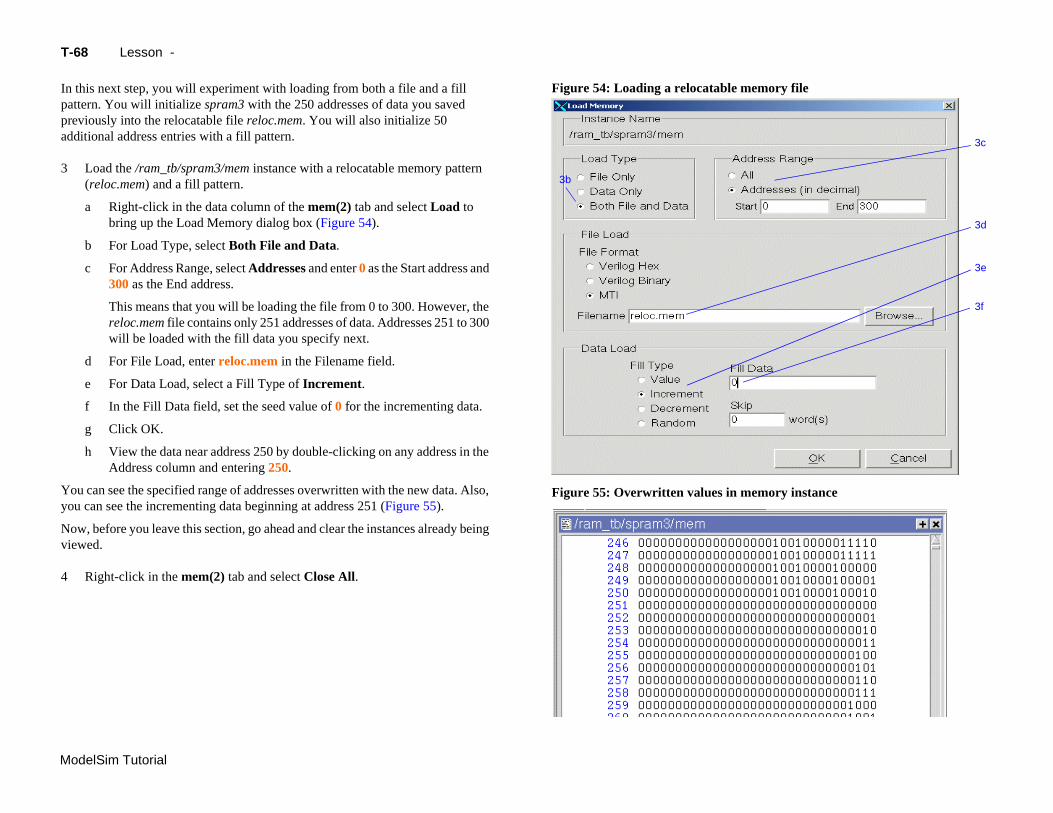
this next step, you will experiment with loading from both a file and a fill ttern. You will initialize spram3 with the 250 addresses of data you saved eviously into the relocatable file reloc.mem. You will also initialize 50 ditional address entries with a fill pattern.
Load the /ram_tb/spram3/mem instance with a relocatable memory pattern (reloc.mem) and a fill pattern.
a Right-click in the data column of the mem(2) tab and select Load to bring up the Load Memory dialog box (Figure 54).
b For Load Type, select Both File and Data.
c For Address Range, select Addresses and enter 0 as the Start address and 300 as the End address.
This means that you will be loading the file from 0 to 300. However, the reloc.mem file contains only 251 addresses of data. Addresses 251 to 300 will be loaded with the fill data you specify next.
d For File Load, enter reloc.mem in the Filename field.
e For Data Load, select a Fill Type of Increment.
f In the Fill Data field, set the seed value of 0 for the incrementing data.
g Click OK.
h View the data near address 250 by double-clicking on any address in the Address column and entering 250.
u can see the specified range of addresses overwritten with the new data. Also, u can see the incrementing data beginning at address 251 (Figure 55).
Figure 54: Loading a relocatabl
Figure 55: Overwritten values i
3b
Interactive debugging commands T-69
ModelSim Tutorial
In
Thpu
1
2
pattern (Figure 58).
tents
ntents for a range of addresses
a range of addresses
2b
2c
2d
Figure 58: Random contents of
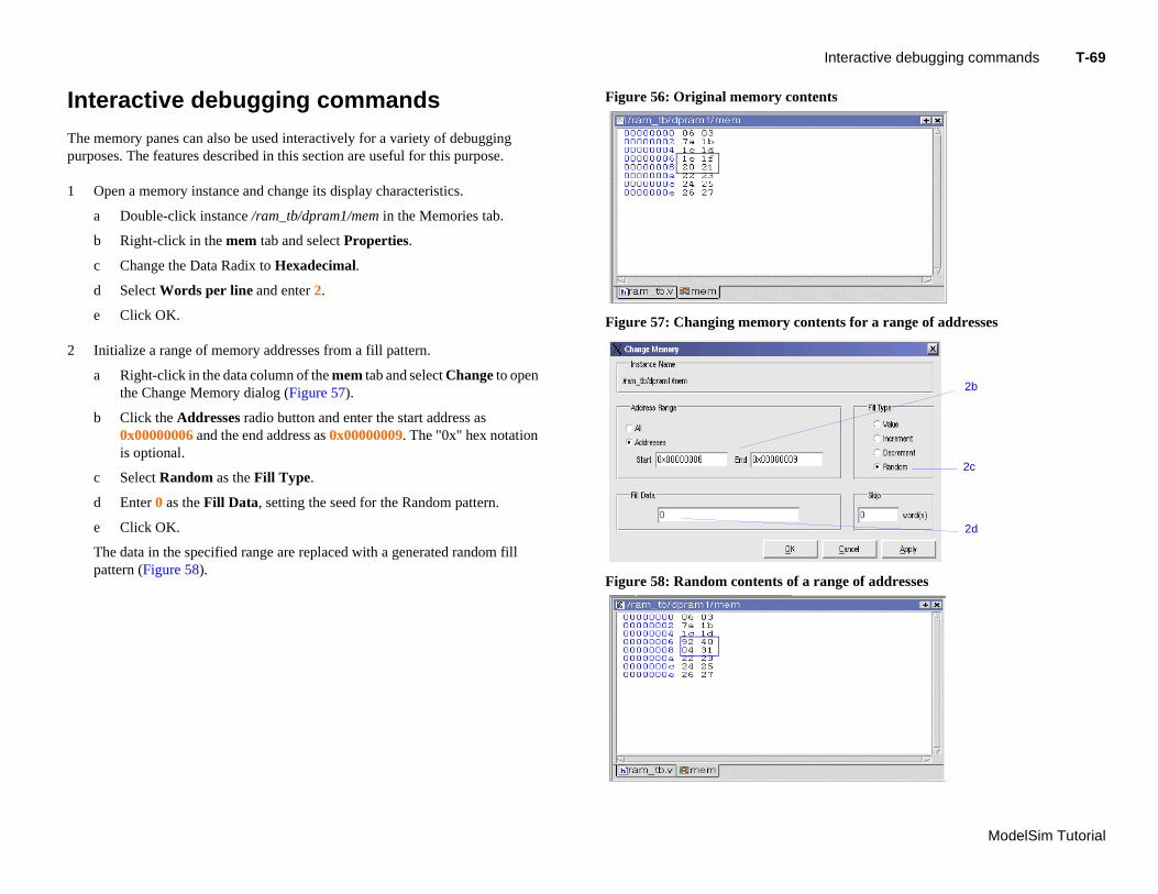
teractive debugging commands
e memory panes can also be used interactively for a variety of debugging rposes. The features described in this section are useful for this purpose.
Open a memory instance and change its display characteristics.
a Double-click instance /ram_tb/dpram1/mem in the Memories tab.
b Right-click in the mem tab and select Properties.
c Change the Data Radix to Hexadecimal.
d Select Words per line and enter 2.
e Click OK.
Initialize a range of memory addresses from a fill pattern.
a Right-click in the data column of the mem tab and select Change to open the Change Memory dialog (Figure 57).
b Click the Addresses radio button and enter the start address as 0x00000006 and the end address as 0x00000009. The "0x" hex notation is optional.
c Select Random as the Fill Type.
d Enter 0 as the Fill Data, setting the seed for the Random pattern.
e Click OK.
The data in the specified range are replaced with a generated random fill
Figure 56: Original memory con
Figure 57: Changing memory co
T-
Mo
3
4
y highlighting
nge
r specified addresses
delSim Tutorial
Figure 61: Changed contents fo
70 Lesson -
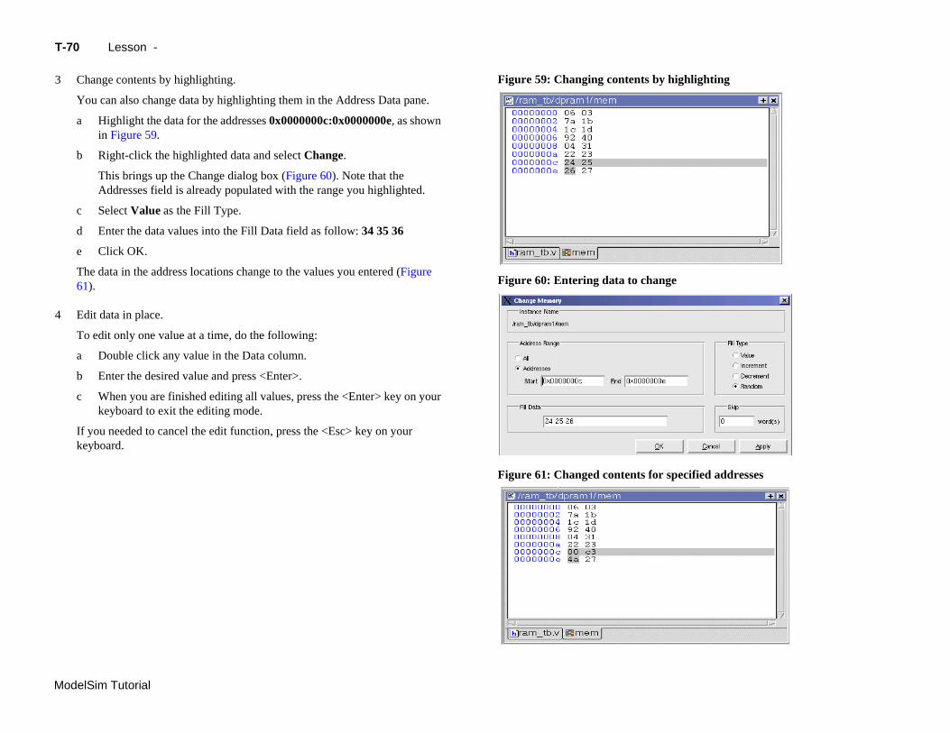
Change contents by highlighting.
You can also change data by highlighting them in the Address Data pane.
a Highlight the data for the addresses 0x0000000c:0x0000000e, as shown in Figure 59.
b Right-click the highlighted data and select Change.
This brings up the Change dialog box (Figure 60). Note that the Addresses field is already populated with the range you highlighted.
c Select Value as the Fill Type.
d Enter the data values into the Fill Data field as follow: 34 35 36
e Click OK.
The data in the address locations change to the values you entered (Figure 61).
Edit data in place.
To edit only one value at a time, do the following:
a Double click any value in the Data column.
b Enter the desired value and press <Enter>.
c When you are finished editing all values, press the <Enter> key on your keyboard to exit the editing mode.
If you needed to cancel the edit function, press the <Esc> key on your keyboard.
Figure 59: Changing contents b
Figure 60: Entering data to cha
Lesson Wrap-up T-71
ModelSim Tutorial
L
Thsim
1
esson Wrap-up
is concludes this lesson. Before continuing we need to end the current ulation.
Select Simulate > End Simulation. Click Yes.

T-
Mo
delSim Tutorial72 Lesson -
ModelSim Tutorial
T-73
Lesson 7 - Automating ModelSim
Topics
The following topics are covered in this lesson:
Introduction . . . . . . . . . . . . . . . . . . . . . . . . . T-74Related reading . . . . . . . . . . . . . . . . . . . . . . . T-74
Creating a simple DO file . . . . . . . . . . . . . . . . . . . . . T-75
Running ModelSim in command-line mode . . . . . . . . . . . . . . . . . T-77
Using Tcl with ModelSim . . . . . . . . . . . . . . . . . . . . . T-80
Le
sson Wrap-up . . . . . . . . . . . . . . . . . . . . . . . . T-82
T-
Mo
In
Asfoaftwhwi
DOcaorsothe
R
M
Pr
delSim Tutorial
74 Lesson -
troduction
ide from executing a couple of pre-existing DO files, the previous lessons cused on using ModelSim in interactive mode: executing single commands, one er another, via the GUI menus or Main window command line. In situations ere you have repetitive tasks to complete, you can increase your productivity th DO files.
files are scripts that allow you to execute many commands at once. The scripts n be as simple as a series of ModelSim commands with associated arguments, they can be full-blown Tcl programs with variables, conditional execution, and forth. You can execute DO files from within the GUI or you can run them from system command prompt without ever invoking the GUI.
elated reading
odelSim User’s Manual – 12 - Tcl and macros (DO files) (UM-123)
actical Programming in Tcl and Tk, Brent B. Welch, Copyright 1997
Important: This lesson assumes that you have added the <install_dir>/modeltech/<platform> directory to your PATH. If you did not, you will need to specify full paths to the tools (i.e., vlib, vmap, vlog, vcom, and vsim) that are used in the lesson.
Creating a simple DO file T-75
ModelSim Tutorial
C
Cryouspr
1
2
3
run 400force reset 0run 200
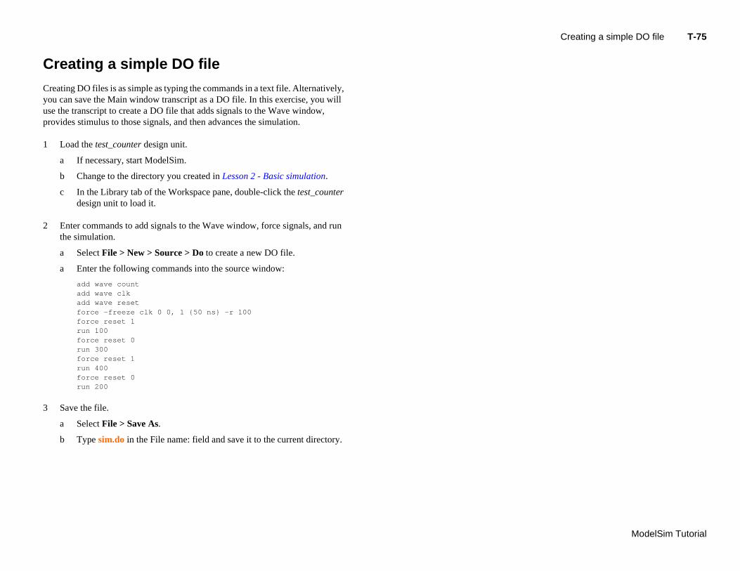
Save the file.
a Select File > Save As.
b Type sim.do in the File name: field and save it to the current directory.
reating a simple DO file
eating DO files is as simple as typing the commands in a text file. Alternatively, u can save the Main window transcript as a DO file. In this exercise, you will e the transcript to create a DO file that adds signals to the Wave window, ovides stimulus to those signals, and then advances the simulation.
Load the test_counter design unit.
a If necessary, start ModelSim.
b Change to the directory you created in Lesson 2 - Basic simulation.
c In the Library tab of the Workspace pane, double-click the test_counter design unit to load it.
Enter commands to add signals to the Wave window, force signals, and run the simulation.
a Select File > New > Source > Do to create a new DO file.
a Enter the following commands into the source window:
add wave countadd wave clkadd wave resetforce -freeze clk 0 0, 1 {50 ns} -r 100force reset 1run 100force reset 0run 300force reset 1
T-
Mo
4
5
delSim Tutorial
76 Lesson -
Load the simulation again and use the DO file.
a Type quit -sim at the VSIM> prompt.
b Type vsim test_counter at the ModelSim> prompt.
c Type do sim.do at the VSIM> prompt.
ModelSim executes the saved commands and draws the waves in the Wave window.
When you are done with this exercise, select File > Quit to quit ModelSim.
ng ModelSim in command-line mode T-77
ModelSim Tutorial
R
WDO(e.invthathe
1
2
Runni
unning ModelSim in command-line mode
e use the term "command-line mode" to refer to simulations that are run from a S/ UNIX prompt without invoking the GUI. Several ModelSim commands
g., vsim, vlib, vlog, etc.) are actually stand-alone executables that can be oked at the system command prompt. Additionally, you can create a DO file t contains other ModelSim commands and specify that file when you invoke simulator.
Create a new directory and copy the tutorial files into it.
Start by creating a new directory for this exercise. Create the directory and copy these files into it:
• \<install_dir>\modeltech\examples\counter.v
• \<install_dir>\modeltech\examples\stim.do
We have used the Verilog file counter.v in this example. If you have a VHDL license, use counter.vhd instead.
Create a new design library and compile the source file.
Again, enter these commands at a DOS/ UNIX prompt in the new directory you created in step 1.
a Type vlib work at the DOS/ UNIX prompt.
b For Verilog, type vlog counter.v at the DOS/ UNIX prompt. For VHDL, type vcom counter.vhd.
T-
Mo
3
4
5
ns /counter/count
delSim Tutorial
delta /counter/clk /counter/reset 0 +0 x z * 1 +0 0 z * 50 +0 0 * * 100 +0 0 0 * 100 +1 0 0 0 150 +0 0 * 0 151 +0 1 * 0 200 +0 1 0 0 250 +0 1 * 0
.
.
.
78 Lesson -
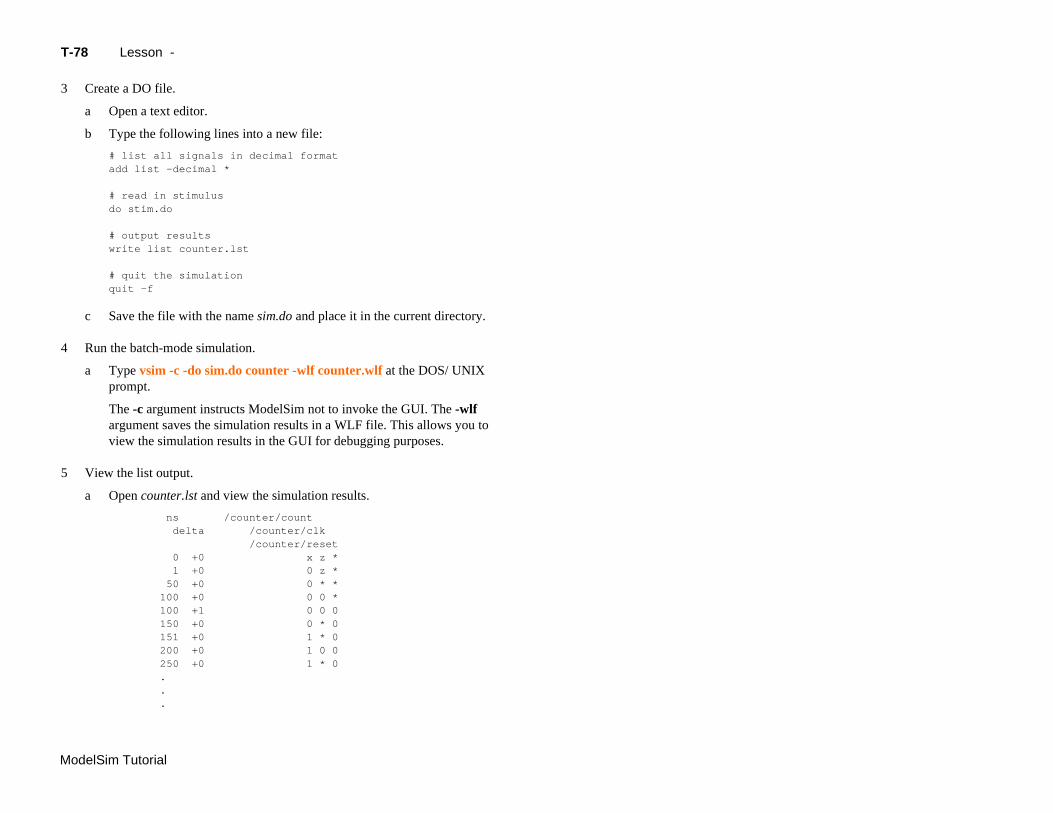
Create a DO file.
a Open a text editor.
b Type the following lines into a new file:
# list all signals in decimal formatadd list -decimal *
# read in stimulusdo stim.do
# output resultswrite list counter.lst
# quit the simulationquit -f
c Save the file with the name sim.do and place it in the current directory.
Run the batch-mode simulation.
a Type vsim -c -do sim.do counter -wlf counter.wlf at the DOS/ UNIX prompt.
The -c argument instructs ModelSim not to invoke the GUI. The -wlf argument saves the simulation results in a WLF file. This allows you to view the simulation results in the GUI for debugging purposes.
View the list output.
a Open counter.lst and view the simulation results.
ng ModelSim in command-line mode T-79
ModelSim Tutorial
6
7
window Workspace
Runni
This is the output produced by the Verilog version of the design. It may appear slightly different if you used the VHDL version.
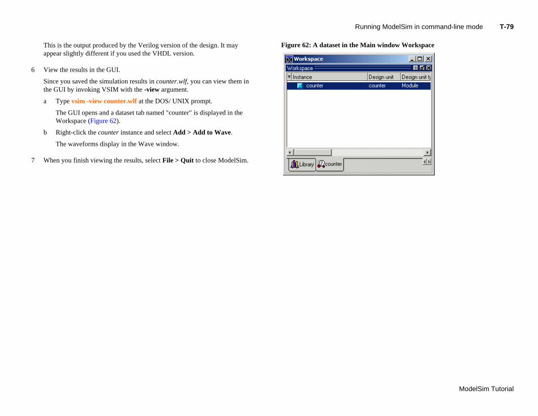
View the results in the GUI.
Since you saved the simulation results in counter.wlf, you can view them in the GUI by invoking VSIM with the -view argument.
a Type vsim -view counter.wlf at the DOS/ UNIX prompt.
The GUI opens and a dataset tab named "counter" is displayed in the Workspace (Figure 62).
b Right-click the counter instance and select Add > Add to Wave.
The waveforms display in the Wave window.
When you finish viewing the results, select File > Quit to close ModelSim.
Figure 62: A dataset in the Main
T-
Mo
U
ThHovafu
Insigexin
1
b Now add these lines to the bottom of the script:
delSim Tutorial
add wave -r /*when {clk'event and clk="1"} { echo "Count is [exa count]" if {[exa count]== "00100111"} { add_wave_zoom $now 1 } elseif {[exa count]== "01000111"} { add_wave_zoom $now 2 }}
80 Lesson -
sing Tcl with ModelSim
e DO files used in previous exercises contained only ModelSim commands. wever, DO files are really just Tcl scripts. This means you can include a whole
riety of Tcl constructs such as procedures, conditional operators, math and trig nctions, regular expressions, and so forth.
this exercise you’ll create a simple Tcl script that tests for certain values on a nal and then adds bookmarks that zoom the Wave window when that value ists. Bookmarks allow you to save a particular zoom range and scroll position the Wave window.
Create the script.
a In a text editor, open a new file and enter the following lines:
proc add_wave_zoom {stime num} {echo "Bookmarking wave $num"bookmark add wave "bk$num" "[expr $stime - 50] [expr $stime +
100]" 0}
These commands do the following:
• Create a new procedure called "add_wave_zoom" that has two arguments, stime and num.
• Create a bookmark with a zoom range from the current simulation time minus 50 time units to the current simulation time plus 100 time units.
Using Tcl with ModelSim T-81
ModelSim Tutorial
2
3
These commands do the following:
• Add all signals to the Wave window.
• Use a when statement to identify when clk transitions to 1.
• Examine the value of count at those transitions and add a bookmark if it is a certain value.
c Save the script with the name "add_bkmrk.do."
Save it into the directory you created in Lesson 2 - Basic simulation.
Load the test_counter design unit.
a Start ModelSim.
b Select File > Change Directory and change to the directory you saved the DO file to in step 1c above.
c In the Library tab of the Main window, expand the work library and double-click the test_counter design unit.
Execute the DO file and run the design.
a Type do add_bkmrk.do at the VSIM> prompt.
b Type run 1500 ns at the VSIM> prompt.
c The simulation runs and the DO file creates two bookmarks.Select View > Bookmarks > bm1.
Watch the Wave window zoom on and scroll to the time when count is 00100111. Try the bm2 bookmark as well.

T-
Mo
L
Th
1
delSim Tutorial
82 Lesson -
esson Wrap-up
is concludes this lesson.
Select File > Quit to close ModelSim.
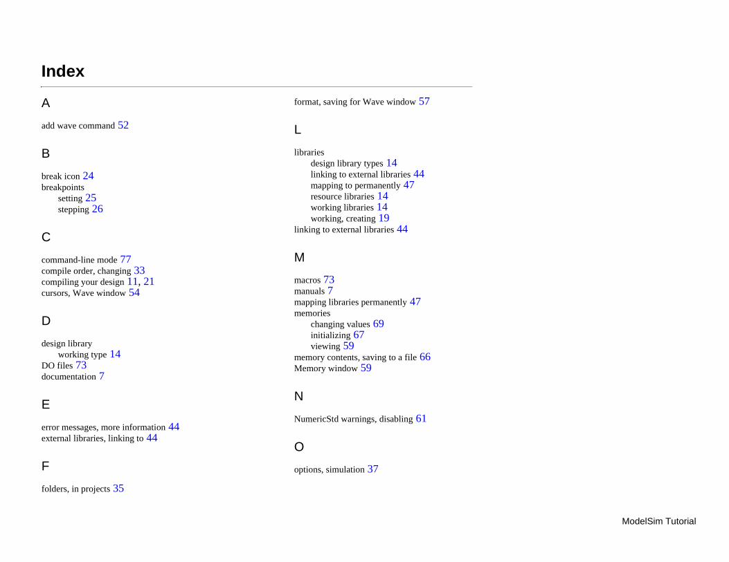
ModelSim Tutorial
Index
A
add wave command 52
B
break icon 24breakpoints
setting 2stepping
C
comcomcomcurso
D
desig
DO fdocu
E
errorexter
F
folde
format, saving for Wave window 57
L
librariesdesign library types 14linking to external libraries 44mapping to permanently 47
mand-line mpile order, cpiling your rs, Wave w
n libraryworking typiles 73mentation
messages,nal librarie
rs, in proje
526
ode 77hanging 33design 11, 21indow 54
e 14
7
more information 44s, linking to 44
cts 35
resource libraries 14working libraries 14working, creating 19
linking to external libraries 44
M
macros 73manuals 7mapping libraries permanently 47memories
changing values 69initializing 67viewing 59
memory contents, saving to a file 66Memory window 59
N
NumericStd warnings, disabling 61
O
options, simulation 37
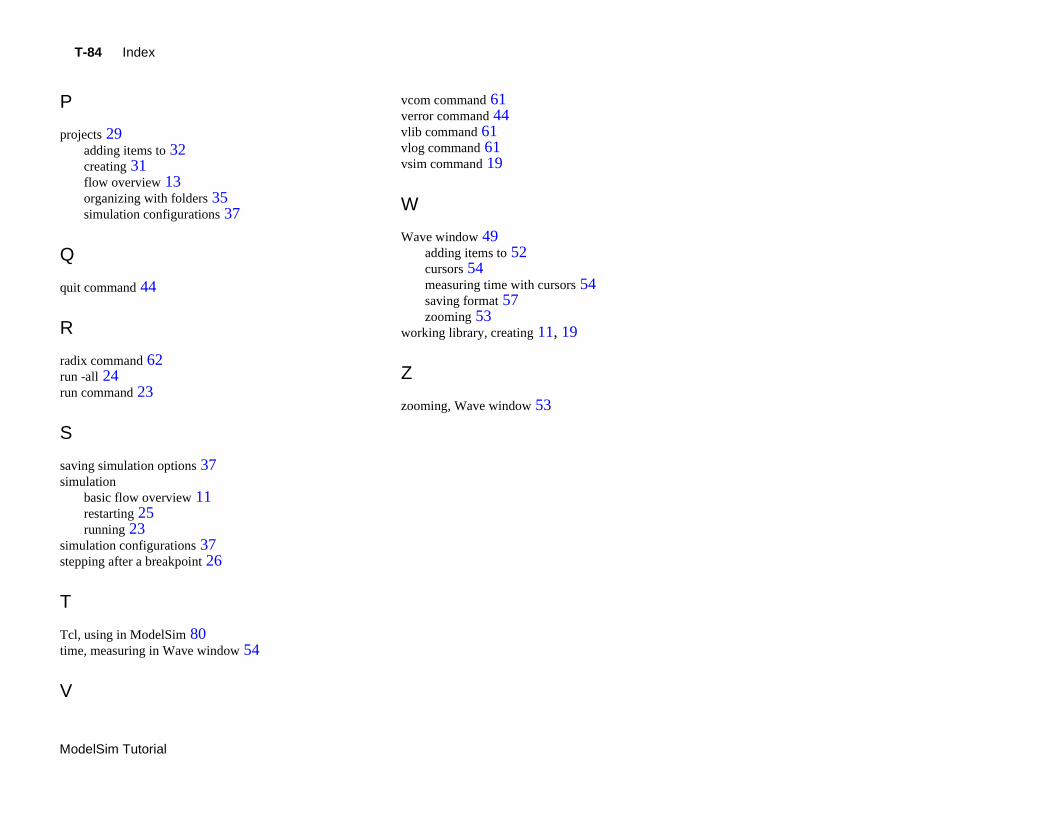
T-84 Index
Mod
P
projects 29adding items to 32creating 31flow overview 13organizing with folders 35simulation configurations 37
Q
quit command 44
R
radixrun -run c
S
savinsimu
simustepp
T
Tcl, time,
V
vcom command 61verror command 44vlib command 61vlog command 61vsim command 19
W
Wave window 49adding items to 52cursors 54measuring time with cursors 54saving format 57zooming 53
elSim Tutorial
command 62all 24ommand 23
g simulation options 37lationbasic flow overview 11restarting 25running 23lation configurations 37ing after a breakpoint 26
using in ModelSim 80 measuring in Wave window 54
working library, creating 11, 19
Z
zooming, Wave window 53