Embed Size (px)
Citation preview
ModelSim® Tutorial
Software Version 6.4b
© 1991-2008 Mentor Graphics CorporationAll rights reserved.
This document contains information that is proprietary to Mentor Graphics Corporation. The original recipient of thisdocument may duplicate this document in whole or in part for internal business purposes only, provided that this entirenotice appears in all copies. In duplicating any part of this document, the recipient agrees to make every reasonableeffort to prevent the unauthorized use and distribution of the proprietary information.

This document is for information and instruction purposes. Mentor Graphics reserves the right to makechanges in specifications and other information contained in this publication without prior notice, and thereader should, in all cases, consult Mentor Graphics to determine whether any changes have beenmade.
The terms and conditions governing the sale and licensing of Mentor Graphics products are set forth inwritten agreements between Mentor Graphics and its customers. No representation or other affirmationof fact contained in this publication shall be deemed to be a warranty or give rise to any liability of MentorGraphics whatsoever.
MENTOR GRAPHICS MAKES NO WARRANTY OF ANY KIND WITH REGARD TO THIS MATERIALINCLUDING, BUT NOT LIMITED TO, THE IMPLIED WARRANTIES OF MERCHANTABILITY ANDFITNESS FOR A PARTICULAR PURPOSE.
MENTOR GRAPHICS SHALL NOT BE LIABLE FOR ANY INCIDENTAL, INDIRECT, SPECIAL, ORCONSEQUENTIAL DAMAGES WHATSOEVER (INCLUDING BUT NOT LIMITED TO LOST PROFITS)ARISING OUT OF OR RELATED TO THIS PUBLICATION OR THE INFORMATION CONTAINED IN IT,EVEN IF MENTOR GRAPHICS CORPORATION HAS BEEN ADVISED OF THE POSSIBILITY OFSUCH DAMAGES.
RESTRICTED RIGHTS LEGEND 03/97
U.S. Government Restricted Rights. The SOFTWARE and documentation have been developed entirelyat private expense and are commercial computer software provided with restricted rights. Use,duplication or disclosure by the U.S. Government or a U.S. Government subcontractor is subject to therestrictions set forth in the license agreement provided with the software pursuant to DFARS 227.7202-3(a) or as set forth in subparagraph (c)(1) and (2) of the Commercial Computer Software - RestrictedRights clause at FAR 52.227-19, as applicable.
Contractor/manufacturer is:Mentor Graphics Corporation
8005 S.W. Boeckman Road, Wilsonville, Oregon 97070-7777.Telephone: 503.685.7000
Toll-Free Telephone: 800.592.2210Website: www.mentor.com
TRADEMARKS: The trademarks, logos and service marks ("Marks") used herein are the property ofMentor Graphics Corporation or other third parties. No one is permitted to use these Marks without theprior written consent of Mentor Graphics or the respective third-party owner. The use herein of a third-party Mark is not an attempt to indicate Mentor Graphics as a source of a product, but is intended toindicate a product from, or associated with, a particular third party. A current list of Mentor Graphics’trademarks may be viewed at: www.mentor.com/terms_conditions/trademarks.cfm.
ModelSim Tutorial, v6.4b 3
Table of Contents
Chapter 1Introduction. . . . . . . . . . . . . . . . . . . . . . . . . . . . . . . . . . . . . . . . . . . . . . . . . . . . . . . . . . . . . . . 9
Assumptions. . . . . . . . . . . . . . . . . . . . . . . . . . . . . . . . . . . . . . . . . . . . . . . . . . . . . . . . . . . . . . 9Before you Begin . . . . . . . . . . . . . . . . . . . . . . . . . . . . . . . . . . . . . . . . . . . . . . . . . . . . . . . . . . 9
Example Designs . . . . . . . . . . . . . . . . . . . . . . . . . . . . . . . . . . . . . . . . . . . . . . . . . . . . . . . . 9
Chapter 2Conceptual Overview . . . . . . . . . . . . . . . . . . . . . . . . . . . . . . . . . . . . . . . . . . . . . . . . . . . . . . . 11
Basic Simulation Flow. . . . . . . . . . . . . . . . . . . . . . . . . . . . . . . . . . . . . . . . . . . . . . . . . . . . . . 11Project Flow. . . . . . . . . . . . . . . . . . . . . . . . . . . . . . . . . . . . . . . . . . . . . . . . . . . . . . . . . . . . . . 12Multiple Library Flow . . . . . . . . . . . . . . . . . . . . . . . . . . . . . . . . . . . . . . . . . . . . . . . . . . . . . . 13Debugging Tools . . . . . . . . . . . . . . . . . . . . . . . . . . . . . . . . . . . . . . . . . . . . . . . . . . . . . . . . . . 14
Chapter 3Basic Simulation . . . . . . . . . . . . . . . . . . . . . . . . . . . . . . . . . . . . . . . . . . . . . . . . . . . . . . . . . . . 15
Create the Working Design Library. . . . . . . . . . . . . . . . . . . . . . . . . . . . . . . . . . . . . . . . . . . . 16Run the Simulation . . . . . . . . . . . . . . . . . . . . . . . . . . . . . . . . . . . . . . . . . . . . . . . . . . . . . . . . 20Set Breakpoints and Step through the Source . . . . . . . . . . . . . . . . . . . . . . . . . . . . . . . . . . . . 22Navigating the Interface. . . . . . . . . . . . . . . . . . . . . . . . . . . . . . . . . . . . . . . . . . . . . . . . . . . . . 25
Chapter 4Projects. . . . . . . . . . . . . . . . . . . . . . . . . . . . . . . . . . . . . . . . . . . . . . . . . . . . . . . . . . . . . . . . . . . 31
Create a New Project . . . . . . . . . . . . . . . . . . . . . . . . . . . . . . . . . . . . . . . . . . . . . . . . . . . . . . . 31Add Objects to the Project . . . . . . . . . . . . . . . . . . . . . . . . . . . . . . . . . . . . . . . . . . . . . . . . . 32Changing Compile Order (VHDL) . . . . . . . . . . . . . . . . . . . . . . . . . . . . . . . . . . . . . . . . . . . 34Compile the Design. . . . . . . . . . . . . . . . . . . . . . . . . . . . . . . . . . . . . . . . . . . . . . . . . . . . . . . 35Load the Design . . . . . . . . . . . . . . . . . . . . . . . . . . . . . . . . . . . . . . . . . . . . . . . . . . . . . . . . . 36
Organizing Projects with Folders. . . . . . . . . . . . . . . . . . . . . . . . . . . . . . . . . . . . . . . . . . . . . . 37Add Folders. . . . . . . . . . . . . . . . . . . . . . . . . . . . . . . . . . . . . . . . . . . . . . . . . . . . . . . . . . . . . 37Moving Files to Folders . . . . . . . . . . . . . . . . . . . . . . . . . . . . . . . . . . . . . . . . . . . . . . . . . . . 39
Simulation Configurations . . . . . . . . . . . . . . . . . . . . . . . . . . . . . . . . . . . . . . . . . . . . . . . . . . . 39
Chapter 5Working With Multiple Libraries. . . . . . . . . . . . . . . . . . . . . . . . . . . . . . . . . . . . . . . . . . . . . 43
Creating the Resource Library . . . . . . . . . . . . . . . . . . . . . . . . . . . . . . . . . . . . . . . . . . . . . . . . 43Creating the Project . . . . . . . . . . . . . . . . . . . . . . . . . . . . . . . . . . . . . . . . . . . . . . . . . . . . . . . . 45Linking to the Resource Library . . . . . . . . . . . . . . . . . . . . . . . . . . . . . . . . . . . . . . . . . . . . . . 46
Linking in Verilog. . . . . . . . . . . . . . . . . . . . . . . . . . . . . . . . . . . . . . . . . . . . . . . . . . . . . . . . 48Linking in VHDL . . . . . . . . . . . . . . . . . . . . . . . . . . . . . . . . . . . . . . . . . . . . . . . . . . . . . . . . 49
Permanently Mapping VHDL Resource Libraries . . . . . . . . . . . . . . . . . . . . . . . . . . . . . . . . 51
Table of Contents
4 ModelSim Tutorial, v6.4b
Chapter 6Analyzing Waveforms . . . . . . . . . . . . . . . . . . . . . . . . . . . . . . . . . . . . . . . . . . . . . . . . . . . . . . 53
Loading a Design . . . . . . . . . . . . . . . . . . . . . . . . . . . . . . . . . . . . . . . . . . . . . . . . . . . . . . . . . . 54Add Objects to the Wave Window . . . . . . . . . . . . . . . . . . . . . . . . . . . . . . . . . . . . . . . . . . . . 54Zooming the Waveform Display . . . . . . . . . . . . . . . . . . . . . . . . . . . . . . . . . . . . . . . . . . . . . . 55Using Cursors in the Wave Window . . . . . . . . . . . . . . . . . . . . . . . . . . . . . . . . . . . . . . . . . . . 56
Working with a Single Cursor . . . . . . . . . . . . . . . . . . . . . . . . . . . . . . . . . . . . . . . . . . . . . . 56Working with Multiple Cursors . . . . . . . . . . . . . . . . . . . . . . . . . . . . . . . . . . . . . . . . . . . . . 58
Chapter 7Viewing And Initializing Memories . . . . . . . . . . . . . . . . . . . . . . . . . . . . . . . . . . . . . . . . . . . 61
View a Memory and its Contents. . . . . . . . . . . . . . . . . . . . . . . . . . . . . . . . . . . . . . . . . . . . . . 62Navigate Within the Memory . . . . . . . . . . . . . . . . . . . . . . . . . . . . . . . . . . . . . . . . . . . . . . . 65
Export Memory Data to a File . . . . . . . . . . . . . . . . . . . . . . . . . . . . . . . . . . . . . . . . . . . . . . . . 67Initialize a Memory . . . . . . . . . . . . . . . . . . . . . . . . . . . . . . . . . . . . . . . . . . . . . . . . . . . . . . . . 69Interactive Debugging Commands . . . . . . . . . . . . . . . . . . . . . . . . . . . . . . . . . . . . . . . . . . . . 72
Chapter 8Automating Simulation . . . . . . . . . . . . . . . . . . . . . . . . . . . . . . . . . . . . . . . . . . . . . . . . . . . . . 77
Creating a Simple DO File. . . . . . . . . . . . . . . . . . . . . . . . . . . . . . . . . . . . . . . . . . . . . . . . . . . 77Running in Command-Line Mode . . . . . . . . . . . . . . . . . . . . . . . . . . . . . . . . . . . . . . . . . . . . . 78Using Tcl with the Simulator. . . . . . . . . . . . . . . . . . . . . . . . . . . . . . . . . . . . . . . . . . . . . . . . . 81
Index
End-User License Agreement

5 ModelSim Tutorial, v6.4b
List of Examples
6 ModelSim Tutorial, v6.4b
List of Figures
Figure 2-1. Basic Simulation Flow - Overview Lab . . . . . . . . . . . . . . . . . . . . . . . . . . . . . . . 11Figure 2-2. Project Flow . . . . . . . . . . . . . . . . . . . . . . . . . . . . . . . . . . . . . . . . . . . . . . . . . . . . 13Figure 2-3. Multiple Library Flow. . . . . . . . . . . . . . . . . . . . . . . . . . . . . . . . . . . . . . . . . . . . . 14Figure 3-1. Basic Simulation Flow - Simulation Lab . . . . . . . . . . . . . . . . . . . . . . . . . . . . . . 15Figure 3-2. The Create a New Library Dialog. . . . . . . . . . . . . . . . . . . . . . . . . . . . . . . . . . . . 16Figure 3-3. work Library in the Workspace. . . . . . . . . . . . . . . . . . . . . . . . . . . . . . . . . . . . . . 17Figure 3-4. Compile Source Files Dialog . . . . . . . . . . . . . . . . . . . . . . . . . . . . . . . . . . . . . . . 18Figure 3-5. Verilog Modules Compiled into work Library . . . . . . . . . . . . . . . . . . . . . . . . . . 18Figure 3-6. Loading Design with Start Simulation Dialog . . . . . . . . . . . . . . . . . . . . . . . . . . 19Figure 3-7. Workspace sim Tab Displays Design Hierarchy . . . . . . . . . . . . . . . . . . . . . . . . 20Figure 3-8. Object Pane Displays Design Objects. . . . . . . . . . . . . . . . . . . . . . . . . . . . . . . . . 20Figure 3-9. Using the Popup Menu to Add Signals to Wave Window . . . . . . . . . . . . . . . . . 21Figure 3-10. Waves Drawn in Wave Window. . . . . . . . . . . . . . . . . . . . . . . . . . . . . . . . . . . . 22Figure 3-11. Setting Breakpoint in Source Window . . . . . . . . . . . . . . . . . . . . . . . . . . . . . . . 23Figure 3-12. Setting Restart Functions . . . . . . . . . . . . . . . . . . . . . . . . . . . . . . . . . . . . . . . . . 24Figure 3-13. Blue Arrow Indicates Where Simulation Stopped. . . . . . . . . . . . . . . . . . . . . . . 24Figure 3-14. Values Shown in Objects Window . . . . . . . . . . . . . . . . . . . . . . . . . . . . . . . . . . 25Figure 3-15. Parameter Name and Value in Source Examine Window . . . . . . . . . . . . . . . . 25Figure 3-16. The Main Window . . . . . . . . . . . . . . . . . . . . . . . . . . . . . . . . . . . . . . . . . . . . . . 26Figure 3-17. Window/Pane Control Icons . . . . . . . . . . . . . . . . . . . . . . . . . . . . . . . . . . . . . . . 27Figure 3-18. zooming in on Workspace Pane . . . . . . . . . . . . . . . . . . . . . . . . . . . . . . . . . . . . 28Figure 3-19. Panes Rearranged in Main Window . . . . . . . . . . . . . . . . . . . . . . . . . . . . . . . . . 29Figure 4-1. Create Project Dialog - Project Lab . . . . . . . . . . . . . . . . . . . . . . . . . . . . . . . . . . 32Figure 4-2. Adding New Items to a Project . . . . . . . . . . . . . . . . . . . . . . . . . . . . . . . . . . . . . . 33Figure 4-3. Add file to Project Dialog . . . . . . . . . . . . . . . . . . . . . . . . . . . . . . . . . . . . . . . . . . 33Figure 4-4. Newly Added Project Files Display a “?” for Status . . . . . . . . . . . . . . . . . . . . . 34Figure 4-5. Compile Order Dialog. . . . . . . . . . . . . . . . . . . . . . . . . . . . . . . . . . . . . . . . . . . . . 35Figure 4-6. Library Tab with Expanded Library . . . . . . . . . . . . . . . . . . . . . . . . . . . . . . . . . . 36Figure 4-7. Structure Tab for a Loaded Design . . . . . . . . . . . . . . . . . . . . . . . . . . . . . . . . . . . 36Figure 4-8. Adding New Folder to Project . . . . . . . . . . . . . . . . . . . . . . . . . . . . . . . . . . . . . . 37Figure 4-9. A Folder Within a Project . . . . . . . . . . . . . . . . . . . . . . . . . . . . . . . . . . . . . . . . . . 38Figure 4-10. Creating Subfolder . . . . . . . . . . . . . . . . . . . . . . . . . . . . . . . . . . . . . . . . . . . . . . 38Figure 4-11. A folder with a Sub-folder . . . . . . . . . . . . . . . . . . . . . . . . . . . . . . . . . . . . . . . . 38Figure 4-12. Changing File Location via the Project Compiler Settings Dialog. . . . . . . . . . 39Figure 4-13. Simulation Configuration Dialog . . . . . . . . . . . . . . . . . . . . . . . . . . . . . . . . . . . 40Figure 4-14. A Simulation Configuration in the Project Tab . . . . . . . . . . . . . . . . . . . . . . . . 41Figure 4-15. Transcript Shows Options for Simulation Configurations . . . . . . . . . . . . . . . . 41Figure 5-1. Creating New Resource Library . . . . . . . . . . . . . . . . . . . . . . . . . . . . . . . . . . . . . 44Figure 5-2. Compiling into the Resource Library . . . . . . . . . . . . . . . . . . . . . . . . . . . . . . . . . 45Figure 5-3. Verilog Simulation Error Reported in Main Window. . . . . . . . . . . . . . . . . . . . . 47

List of Figures
ModelSim Tutorial, v6.4b 7
Figure 5-4. VHDL Simulation Warning Reported in Main Window . . . . . . . . . . . . . . . . . . 47Figure 5-5. Specifying a Search Library in the Simulate Dialog. . . . . . . . . . . . . . . . . . . . . . 49Figure 5-6. Mapping to the parts_lib Library . . . . . . . . . . . . . . . . . . . . . . . . . . . . . . . . . . . . 50Figure 5-7. Adding LIBRARY and USE Statements to the Testbench. . . . . . . . . . . . . . . . . 51Figure 6-1. Panes of the Wave Window . . . . . . . . . . . . . . . . . . . . . . . . . . . . . . . . . . . . . . . . 53Figure 6-2. Undocking the Wave Window . . . . . . . . . . . . . . . . . . . . . . . . . . . . . . . . . . . . . . 55Figure 6-3. Zooming in with the Mouse Pointer . . . . . . . . . . . . . . . . . . . . . . . . . . . . . . . . . . 56Figure 6-4. Working with a Single Cursor in the Wave Window . . . . . . . . . . . . . . . . . . . . . 57Figure 6-5. Renaming a Cursor . . . . . . . . . . . . . . . . . . . . . . . . . . . . . . . . . . . . . . . . . . . . . . . 58Figure 6-6. Interval Measurement Between Two Cursors. . . . . . . . . . . . . . . . . . . . . . . . . . . 59Figure 6-7. A Locked Cursor in the Wave Window . . . . . . . . . . . . . . . . . . . . . . . . . . . . . . . 59Figure 7-1. Viewing the Memories Tab in the Main Window Workspace . . . . . . . . . . . . . . 62Figure 7-2. The mem Tab in the MDI Frame Shows Addresses and Data . . . . . . . . . . . . . . 63Figure 7-3. The Memory Display Updates with the Simulation . . . . . . . . . . . . . . . . . . . . . . 63Figure 7-4. Changing the Address Radix. . . . . . . . . . . . . . . . . . . . . . . . . . . . . . . . . . . . . . . . 64Figure 7-5. New Address Radix and Line Length . . . . . . . . . . . . . . . . . . . . . . . . . . . . . . . . . 65Figure 7-6. Goto Dialog. . . . . . . . . . . . . . . . . . . . . . . . . . . . . . . . . . . . . . . . . . . . . . . . . . . . . 65Figure 7-7. Editing the Address Directly. . . . . . . . . . . . . . . . . . . . . . . . . . . . . . . . . . . . . . . . 66Figure 7-8. Searching for a Specific Data Value . . . . . . . . . . . . . . . . . . . . . . . . . . . . . . . . . . 66Figure 7-9. Export Memory Dialog . . . . . . . . . . . . . . . . . . . . . . . . . . . . . . . . . . . . . . . . . . . . 68Figure 7-10. Import Memory Dialog . . . . . . . . . . . . . . . . . . . . . . . . . . . . . . . . . . . . . . . . . . . 70Figure 7-11. Initialized Memory from File and Fill Pattern . . . . . . . . . . . . . . . . . . . . . . . . . 71Figure 7-12. Data Increments Starting at Address 251 . . . . . . . . . . . . . . . . . . . . . . . . . . . . . 72Figure 7-13. Original Memory Content . . . . . . . . . . . . . . . . . . . . . . . . . . . . . . . . . . . . . . . . . 73Figure 7-14. Changing Memory Content for a Range of Addresses . . . . . . . . . . . . . . . . . . . 73Figure 7-15. Random Content Generated for a Range of Addresses. . . . . . . . . . . . . . . . . . . 74Figure 7-16. Changing Memory Contents by Highlighting. . . . . . . . . . . . . . . . . . . . . . . . . . 74Figure 7-17. Entering Data to Change . . . . . . . . . . . . . . . . . . . . . . . . . . . . . . . . . . . . . . . . . . 75Figure 7-18. Changed Memory Contents for the Specified Addresses . . . . . . . . . . . . . . . . . 75Figure 8-1. A Dataset in the Main Window Workspace . . . . . . . . . . . . . . . . . . . . . . . . . . . . 80

ModelSim Tutorial, v6.4b 8
List of Tables
Table 3-1. The Main Window . . . . . . . . . . . . . . . . . . . . . . . . . . . . . . . . . . . . . . . . . . . . . . . . 26
ModelSim Tutorial, v6.4b 9
Chapter 1Introduction
AssumptionsWe assume that you are familiar with the use of your operating system. You should also befamiliar with the window management functions of your graphic interface: OpenWindows,OSF/Motif, CDE, KDE, GNOME, or Microsoft Windows 2000/XP.
We also assume that you have a working knowledge of the language in which your designand/or testbench is written (i.e., VHDL, Verilog, etc.). Although ModelSim™ is an excellenttool to use while learning HDL concepts and practices, this document is not written to supportthat goal.
Before you BeginPreparation for some of the lessons leaves certain details up to you. You will decide the bestway to create directories, copy files, and execute programs within your operating system.(When you are operating the simulator within ModelSim’s GUI, the interface is consistent forall platforms.)
Examples show Windows path separators - use separators appropriate for your operating systemwhen trying the examples.
Example DesignsModelSim comes with Verilog and VHDL versions of the designs used in these lessons. Thisallows you to do the tutorial regardless of which license type you have. Though we have tried tominimize the differences between the Verilog and VHDL versions, we could not do so in allcases. In cases where the designs differ (e.g., line numbers or syntax), you will find language-specific instructions. Follow the instructions that are appropriate for the language you use.

ModelSim Tutorial, v6.4b10
IntroductionBefore you Begin
ModelSim Tutorial, v6.4b 11
Chapter 2Conceptual Overview
Introduction
ModelSim is a verification and simulation tool for VHDL, Verilog, SystemVerilog, and mixed-language designs.
This lesson provides a brief conceptual overview of the ModelSim simulation environment. It isdivided into fourtopics, which you will learn more about in subsequent lessons.
• Basic simulation flow — Refer to Chapter 3 Basic Simulation.
• Project flow — Refer to Chapter 4 Projects.
• Multiple library flow — Refer to Chapter 5 Working With Multiple Libraries.
• Debugging tools — Refer to remaining lessons.
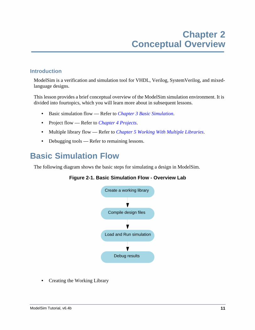
Basic Simulation FlowThe following diagram shows the basic steps for simulating a design in ModelSim.
Figure 2-1. Basic Simulation Flow - Overview Lab
• Creating the Working Library
Create a working library
Compile design files
Load and Run simulation
Debug results
ModelSim Tutorial, v6.4b12
Conceptual OverviewProject Flow
In ModelSim, all designs are compiled into a library. You typically start a newsimulation in ModelSim by creating a working library called "work". "Work" is thelibrary name used by the compiler as the default destination for compiled design units.
• Compiling Your Design
After creating the working library, you compile your design units into it. The ModelSimlibrary format is compatible across all supported platforms. You can simulate yourdesign on any platform without having to recompile your design.
• Loading the Simulator with Your Design and Running the Simulation
With the design compiled, you load the simulator with your design by invoking thesimulator on a top-level module (Verilog) or a configuration or entity/architecture pair(VHDL).
Assuming the design loads successfully, the simulation time is set to zero, and you entera run command to begin simulation.
• Debugging Your Results
If you don’t get the results you expect, you can use ModelSim’s robust debuggingenvironment to track down the cause of the problem.
Project FlowA project is a collection mechanism for an HDL design under specification or test. Even thoughyou don’t have to use projects in ModelSim, they may ease interaction with the tool and areuseful for organizing files and specifying simulation settings.
The following diagram shows the basic steps for simulating a design within a ModelSimproject.
Conceptual OverviewMultiple Library Flow
ModelSim Tutorial, v6.4b 13
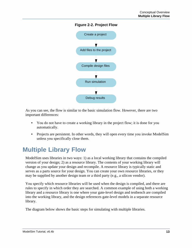
Figure 2-2. Project Flow
As you can see, the flow is similar to the basic simulation flow. However, there are twoimportant differences:
• You do not have to create a working library in the project flow; it is done for youautomatically.
• Projects are persistent. In other words, they will open every time you invoke ModelSimunless you specifically close them.
Multiple Library FlowModelSim uses libraries in two ways: 1) as a local working library that contains the compiledversion of your design; 2) as a resource library. The contents of your working library willchange as you update your design and recompile. A resource library is typically static andserves as a parts source for your design. You can create your own resource libraries, or theymay be supplied by another design team or a third party (e.g., a silicon vendor).
You specify which resource libraries will be used when the design is compiled, and there arerules to specify in which order they are searched. A common example of using both a workinglibrary and a resource library is one where your gate-level design and testbench are compiledinto the working library, and the design references gate-level models in a separate resourcelibrary.
The diagram below shows the basic steps for simulating with multiple libraries.
Create a project
Add files to the project
Run simulation
Debug results
Compile design files
ModelSim Tutorial, v6.4b14
Conceptual OverviewDebugging Tools
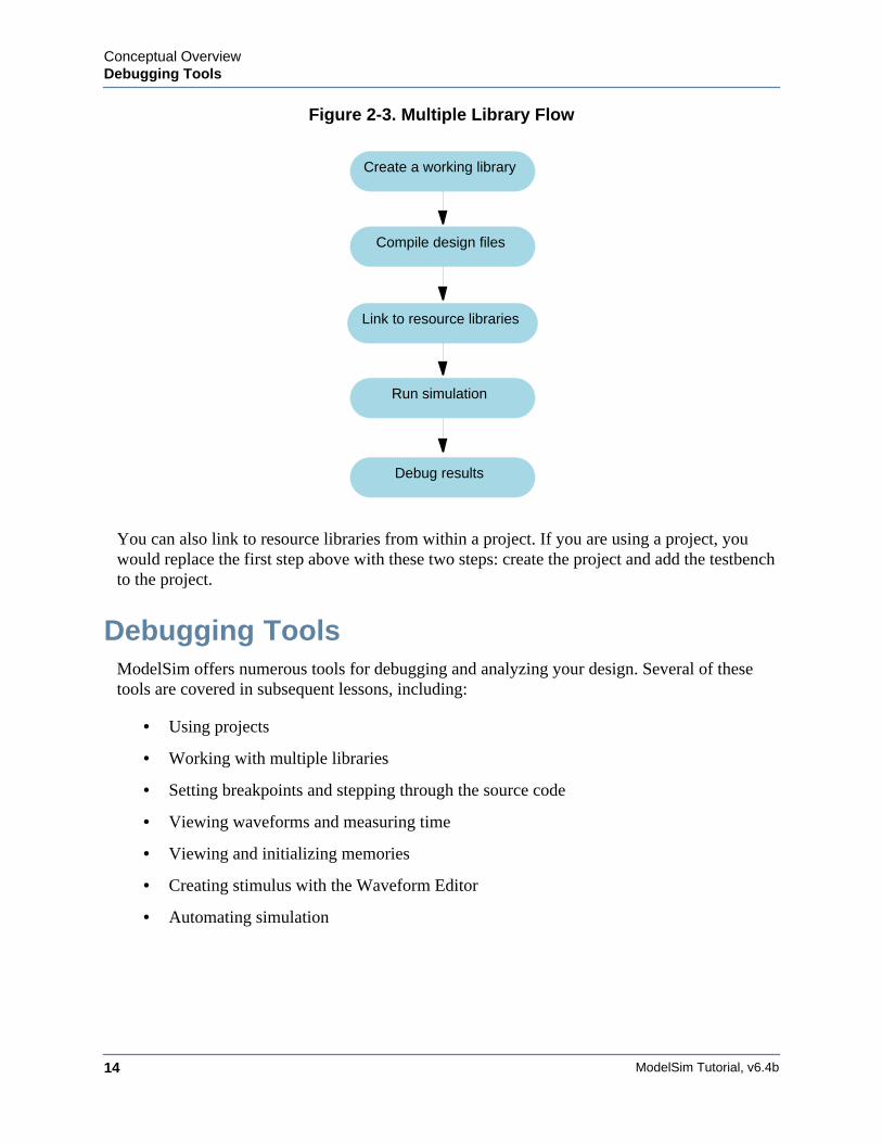
Figure 2-3. Multiple Library Flow
You can also link to resource libraries from within a project. If you are using a project, youwould replace the first step above with these two steps: create the project and add the testbenchto the project.
Debugging ToolsModelSim offers numerous tools for debugging and analyzing your design. Several of thesetools are covered in subsequent lessons, including:
• Using projects
• Working with multiple libraries
• Setting breakpoints and stepping through the source code
• Viewing waveforms and measuring time
• Viewing and initializing memories
• Creating stimulus with the Waveform Editor
• Automating simulation
Create a working library
Compile design files
Run simulation
Debug results
Link to resource libraries
ModelSim Tutorial, v6.4b 15
Chapter 3Basic Simulation
Introduction
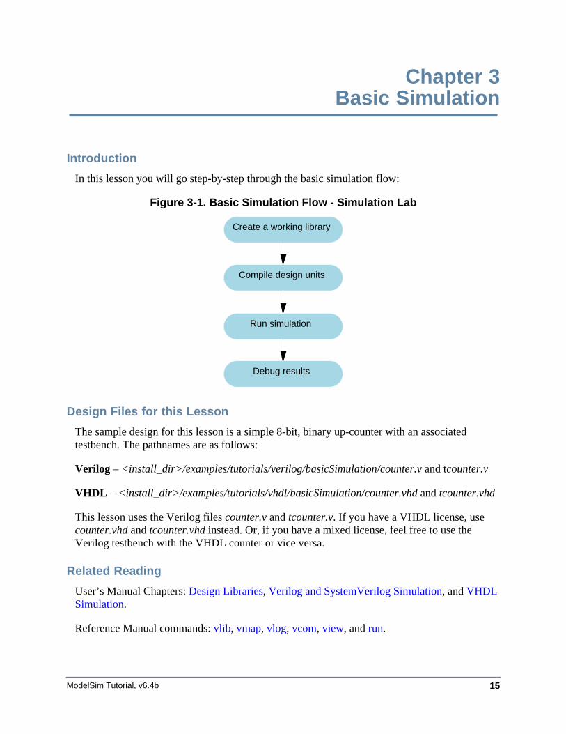
In this lesson you will go step-by-step through the basic simulation flow:
Figure 3-1. Basic Simulation Flow - Simulation Lab
Design Files for this Lesson
The sample design for this lesson is a simple 8-bit, binary up-counter with an associatedtestbench. The pathnames are as follows:
Verilog – <install_dir>/examples/tutorials/verilog/basicSimulation/counter.v and tcounter.v
VHDL – <install_dir>/examples/tutorials/vhdl/basicSimulation/counter.vhd and tcounter.vhd
This lesson uses the Verilog files counter.v and tcounter.v. If you have a VHDL license, usecounter.vhd and tcounter.vhd instead. Or, if you have a mixed license, feel free to use theVerilog testbench with the VHDL counter or vice versa.
Related Reading
User’s Manual Chapters: Design Libraries, Verilog and SystemVerilog Simulation, and VHDLSimulation.
Reference Manual commands: vlib, vmap, vlog, vcom, view, and run.
Debug results
Compile design units
Run simulation
Create a working library
ModelSim Tutorial, v6.4b16
Basic SimulationCreate the Working Design Library
Create the Working Design LibraryBefore you can simulate a design, you must first create a library and compile the source codeinto that library.
1. Create a new directory and copy the design files for this lesson into it.
Start by creating a new directory for this exercise (in case other users will be workingwith these lessons).
Verilog: Copy counter.v and tcounter.v files from/<install_dir>/examples/tutorials/verilog/basicSimulation to the new directory.
VHDL: Copy counter.vhd and tcounter.vhd files from/<install_dir>/examples/tutorials/vhdl/basicSimulation to the new directory.
2. Start ModelSim if necessary.
a. Type vsim at a UNIX shell prompt or use the ModelSim icon in Windows.
Upon opening ModelSim for the first time, you will see the Welcome to ModelSimdialog. Click Close.
b. Select File > Change Directory and change to the directory you created in step 1.
3. Create the working library.
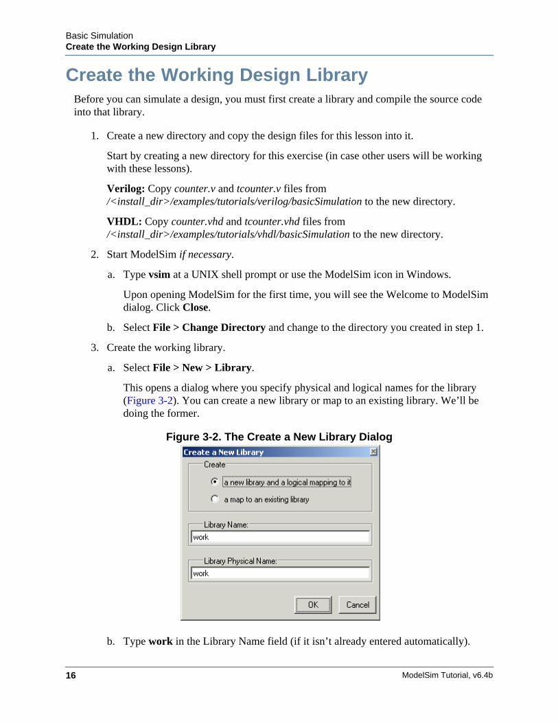
a. Select File > New > Library.
This opens a dialog where you specify physical and logical names for the library(Figure 3-2). You can create a new library or map to an existing library. We’ll bedoing the former.
Figure 3-2. The Create a New Library Dialog
b. Type work in the Library Name field (if it isn’t already entered automatically).
Basic SimulationCreate the Working Design Library
ModelSim Tutorial, v6.4b 17
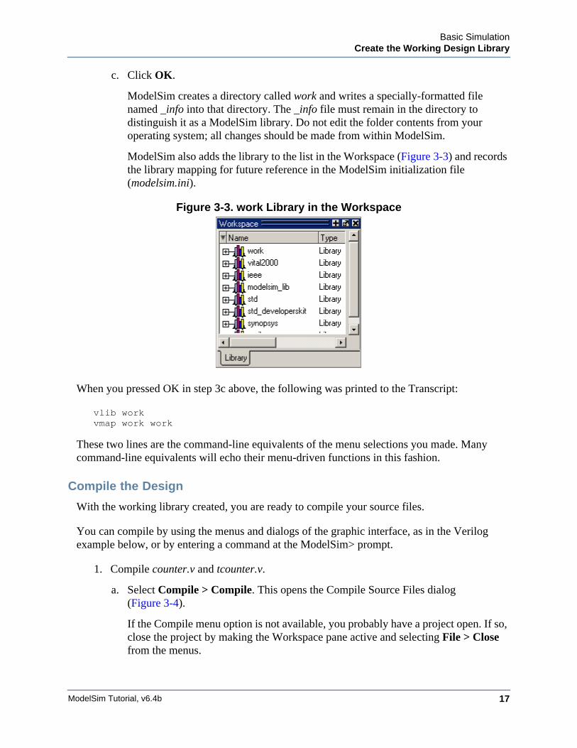
c. Click OK.
ModelSim creates a directory called work and writes a specially-formatted filenamed _info into that directory. The _info file must remain in the directory todistinguish it as a ModelSim library. Do not edit the folder contents from youroperating system; all changes should be made from within ModelSim.
ModelSim also adds the library to the list in the Workspace (Figure 3-3) and recordsthe library mapping for future reference in the ModelSim initialization file(modelsim.ini).
Figure 3-3. work Library in the Workspace
When you pressed OK in step 3c above, the following was printed to the Transcript:
vlib workvmap work work
These two lines are the command-line equivalents of the menu selections you made. Manycommand-line equivalents will echo their menu-driven functions in this fashion.
Compile the Design
With the working library created, you are ready to compile your source files.
You can compile by using the menus and dialogs of the graphic interface, as in the Verilogexample below, or by entering a command at the ModelSim> prompt.
1. Compile counter.v and tcounter.v.
a. Select Compile > Compile. This opens the Compile Source Files dialog(Figure 3-4).
If the Compile menu option is not available, you probably have a project open. If so,close the project by making the Workspace pane active and selecting File > Closefrom the menus.
ModelSim Tutorial, v6.4b18
Basic SimulationCreate the Working Design Library
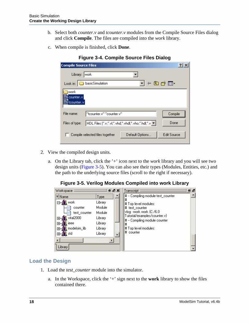
b. Select both counter.v and tcounter.v modules from the Compile Source Files dialogand click Compile. The files are compiled into the work library.
c. When compile is finished, click Done.
Figure 3-4. Compile Source Files Dialog
2. View the compiled design units.
a. On the Library tab, click the ’+’ icon next to the work library and you will see twodesign units (Figure 3-5). You can also see their types (Modules, Entities, etc.) andthe path to the underlying source files (scroll to the right if necessary).
Figure 3-5. Verilog Modules Compiled into work Library
Load the Design
1. Load the test_counter module into the simulator.
a. In the Workspace, click the ‘+’ sign next to the work library to show the filescontained there.
Basic SimulationCreate the Working Design Library
ModelSim Tutorial, v6.4b 19
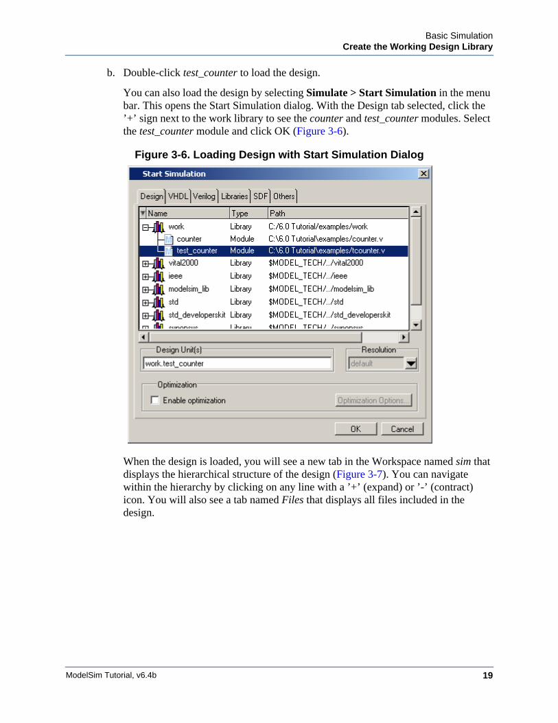
b. Double-click test_counter to load the design.
You can also load the design by selecting Simulate > Start Simulation in the menubar. This opens the Start Simulation dialog. With the Design tab selected, click the’+’ sign next to the work library to see the counter and test_counter modules. Selectthe test_counter module and click OK (Figure 3-6).
Figure 3-6. Loading Design with Start Simulation Dialog
When the design is loaded, you will see a new tab in the Workspace named sim thatdisplays the hierarchical structure of the design (Figure 3-7). You can navigatewithin the hierarchy by clicking on any line with a ’+’ (expand) or ’-’ (contract)icon. You will also see a tab named Files that displays all files included in thedesign.
ModelSim Tutorial, v6.4b20
Basic SimulationRun the Simulation
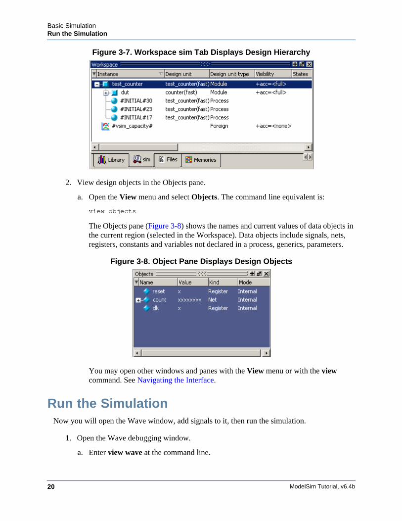
Figure 3-7. Workspace sim Tab Displays Design Hierarchy
2. View design objects in the Objects pane.
a. Open the View menu and select Objects. The command line equivalent is:
view objects
The Objects pane (Figure 3-8) shows the names and current values of data objects inthe current region (selected in the Workspace). Data objects include signals, nets,registers, constants and variables not declared in a process, generics, parameters.
Figure 3-8. Object Pane Displays Design Objects
You may open other windows and panes with the View menu or with the viewcommand. See Navigating the Interface.
Run the SimulationNow you will open the Wave window, add signals to it, then run the simulation.
1. Open the Wave debugging window.
a. Enter view wave at the command line.
Basic SimulationRun the Simulation
ModelSim Tutorial, v6.4b 21
You can also use the View > Wave menu selection to open a Wave window.
The Wave window is one of several windows available for debugging. To see a listof the other debugging windows, select the View menu. You may need to move orresize the windows to your liking. Window panes within the Main window can bezoomed to occupy the entire Main window or undocked to stand alone. For details,see Navigating the Interface.
2. Add signals to the Wave window.
a. In the Workspace pane, select the sim tab.
b. Right-click test_counter to open a popup context menu.
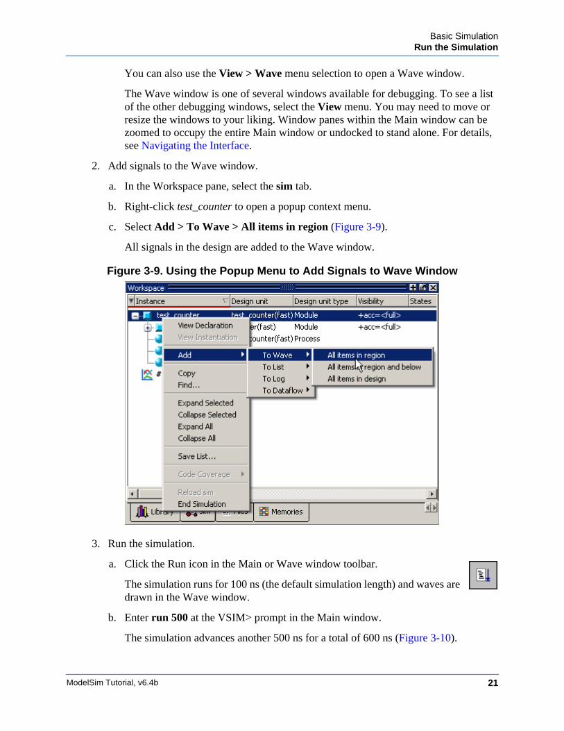
c. Select Add > To Wave > All items in region (Figure 3-9).
All signals in the design are added to the Wave window.
Figure 3-9. Using the Popup Menu to Add Signals to Wave Window
3. Run the simulation.
a. Click the Run icon in the Main or Wave window toolbar.
The simulation runs for 100 ns (the default simulation length) and waves aredrawn in the Wave window.
b. Enter run 500 at the VSIM> prompt in the Main window.
The simulation advances another 500 ns for a total of 600 ns (Figure 3-10).
ModelSim Tutorial, v6.4b22
Basic SimulationSet Breakpoints and Step through the Source
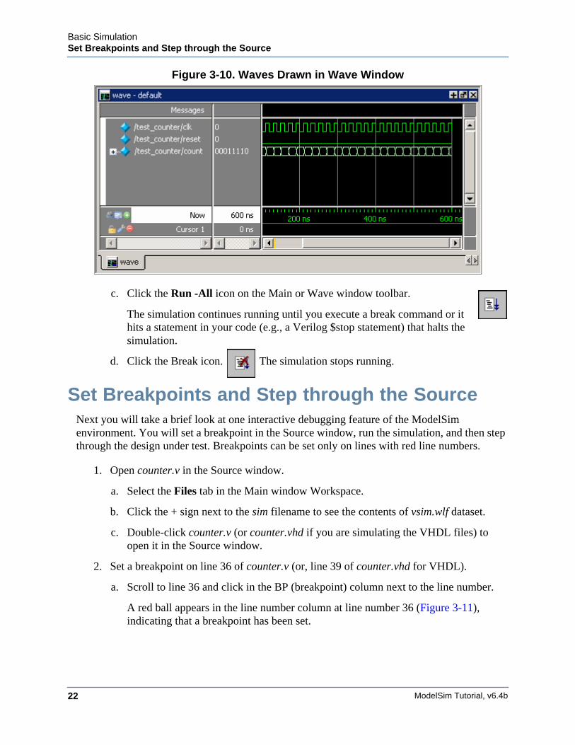
Figure 3-10. Waves Drawn in Wave Window
c. Click the Run -All icon on the Main or Wave window toolbar.
The simulation continues running until you execute a break command or ithits a statement in your code (e.g., a Verilog $stop statement) that halts thesimulation.
d. Click the Break icon. The simulation stops running.
Set Breakpoints and Step through the SourceNext you will take a brief look at one interactive debugging feature of the ModelSimenvironment. You will set a breakpoint in the Source window, run the simulation, and then stepthrough the design under test. Breakpoints can be set only on lines with red line numbers.
1. Open counter.v in the Source window.
a. Select the Files tab in the Main window Workspace.
b. Click the + sign next to the sim filename to see the contents of vsim.wlf dataset.
c. Double-click counter.v (or counter.vhd if you are simulating the VHDL files) toopen it in the Source window.
2. Set a breakpoint on line 36 of counter.v (or, line 39 of counter.vhd for VHDL).
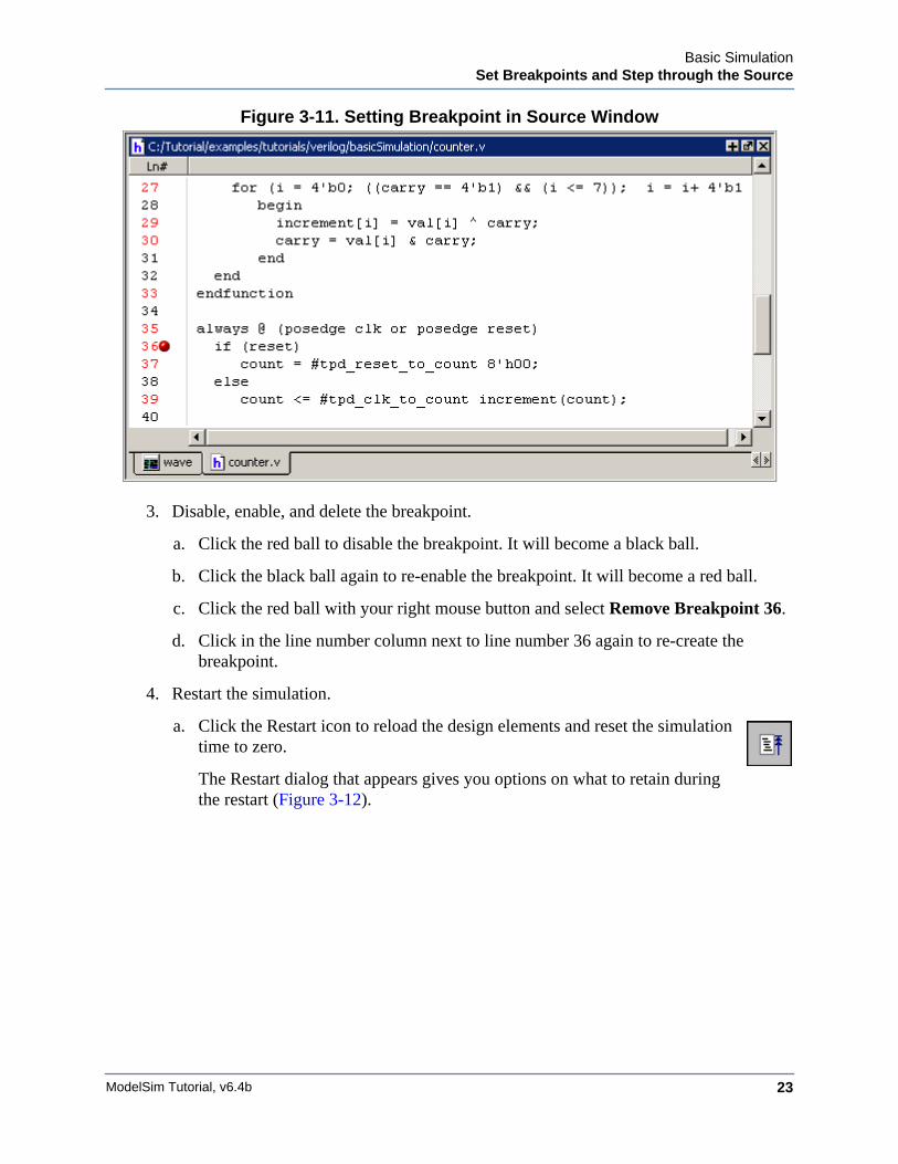
a. Scroll to line 36 and click in the BP (breakpoint) column next to the line number.
A red ball appears in the line number column at line number 36 (Figure 3-11),indicating that a breakpoint has been set.
Basic SimulationSet Breakpoints and Step through the Source
ModelSim Tutorial, v6.4b 23
Figure 3-11. Setting Breakpoint in Source Window
3. Disable, enable, and delete the breakpoint.
a. Click the red ball to disable the breakpoint. It will become a black ball.
b. Click the black ball again to re-enable the breakpoint. It will become a red ball.
c. Click the red ball with your right mouse button and select Remove Breakpoint 36.
d. Click in the line number column next to line number 36 again to re-create thebreakpoint.
4. Restart the simulation.
a. Click the Restart icon to reload the design elements and reset the simulationtime to zero.
The Restart dialog that appears gives you options on what to retain duringthe restart (Figure 3-12).
ModelSim Tutorial, v6.4b24
Basic SimulationSet Breakpoints and Step through the Source
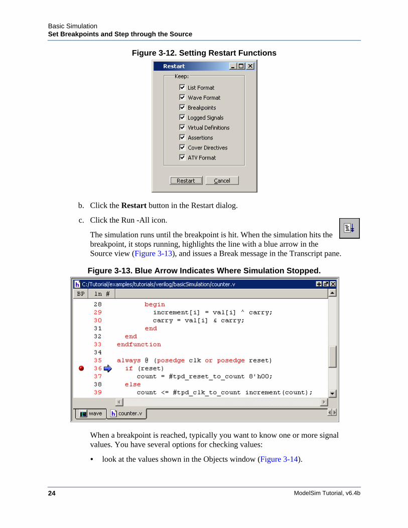
Figure 3-12. Setting Restart Functions
b. Click the Restart button in the Restart dialog.
c. Click the Run -All icon.
The simulation runs until the breakpoint is hit. When the simulation hits thebreakpoint, it stops running, highlights the line with a blue arrow in theSource view (Figure 3-13), and issues a Break message in the Transcript pane.
Figure 3-13. Blue Arrow Indicates Where Simulation Stopped.
When a breakpoint is reached, typically you want to know one or more signalvalues. You have several options for checking values:
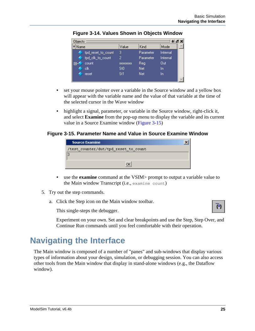
• look at the values shown in the Objects window (Figure 3-14).
Basic SimulationNavigating the Interface
ModelSim Tutorial, v6.4b 25
Figure 3-14. Values Shown in Objects Window
• set your mouse pointer over a variable in the Source window and a yellow boxwill appear with the variable name and the value of that variable at the time ofthe selected cursor in the Wave window
• highlight a signal, parameter, or variable in the Source window, right-click it,and select Examine from the pop-up menu to display the variable and its currentvalue in a Source Examine window (Figure 3-15)
Figure 3-15. Parameter Name and Value in Source Examine Window
• use the examine command at the VSIM> prompt to output a variable value tothe Main window Transcript (i.e., examine count)
5. Try out the step commands.
a. Click the Step icon on the Main window toolbar.
This single-steps the debugger.
Experiment on your own. Set and clear breakpoints and use the Step, Step Over, andContinue Run commands until you feel comfortable with their operation.
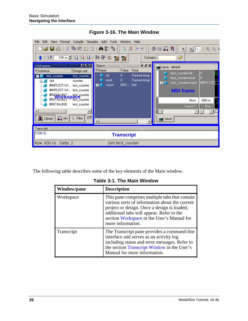
Navigating the InterfaceThe Main window is composed of a number of "panes" and sub-windows that display varioustypes of information about your design, simulation, or debugging session. You can also accessother tools from the Main window that display in stand-alone windows (e.g., the Dataflowwindow).
ModelSim Tutorial, v6.4b26
Basic SimulationNavigating the Interface
Figure 3-16. The Main Window
The following table describes some of the key elements of the Main window.
Table 3-1. The Main Window
Window/pane Description
Workspace This pane comprises multiple tabs that containvarious sorts of information about the currentproject or design. Once a design is loaded,additional tabs will appear. Refer to thesection Workspace in the User’s Manual formore information.
Transcript The Transcript pane provides a command-lineinterface and serves as an activity logincluding status and error messages. Refer tothe section Transcript Window in the User’sManual for more information.
Transcript
WorkspaceMDI frame
Basic SimulationNavigating the Interface
ModelSim Tutorial, v6.4b 27
Here are a few important points to keep in mind about the ModelSim interface:
• Windows/panes can be resized, moved, zoomed, undocked, etc. and the changes arepersistent.
You have a number of options for re-sizing, re-positioning, undocking/redocking, andgenerally modifying the physical characteristics of windows and panes. When you exitModelSim, the current layout is saved so that it appears the same the next time youinvoke the tool. Refer to the Main Window section in the User’s Manual for moreinformation.
• Menus are context sensitive.
The menu items that are available and how certain menu items behave depend on whichpane or window is active. For example, if the sim tab in the Workspace is active and youchoose Edit from the menu bar, the Clear command is disabled. However, if you click inthe Transcript pane and choose Edit, the Clear command is enabled. The active pane isdenoted by a blue title bar.
Let us try a few things.
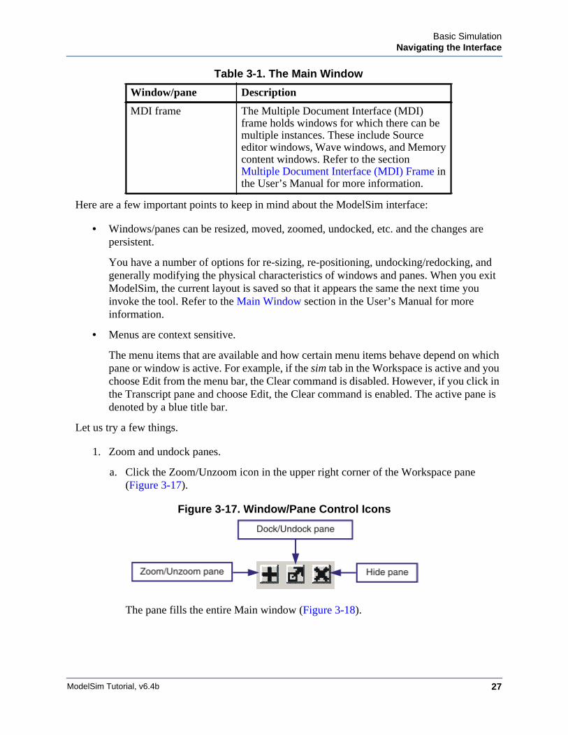
1. Zoom and undock panes.
a. Click the Zoom/Unzoom icon in the upper right corner of the Workspace pane(Figure 3-17).
Figure 3-17. Window/Pane Control Icons
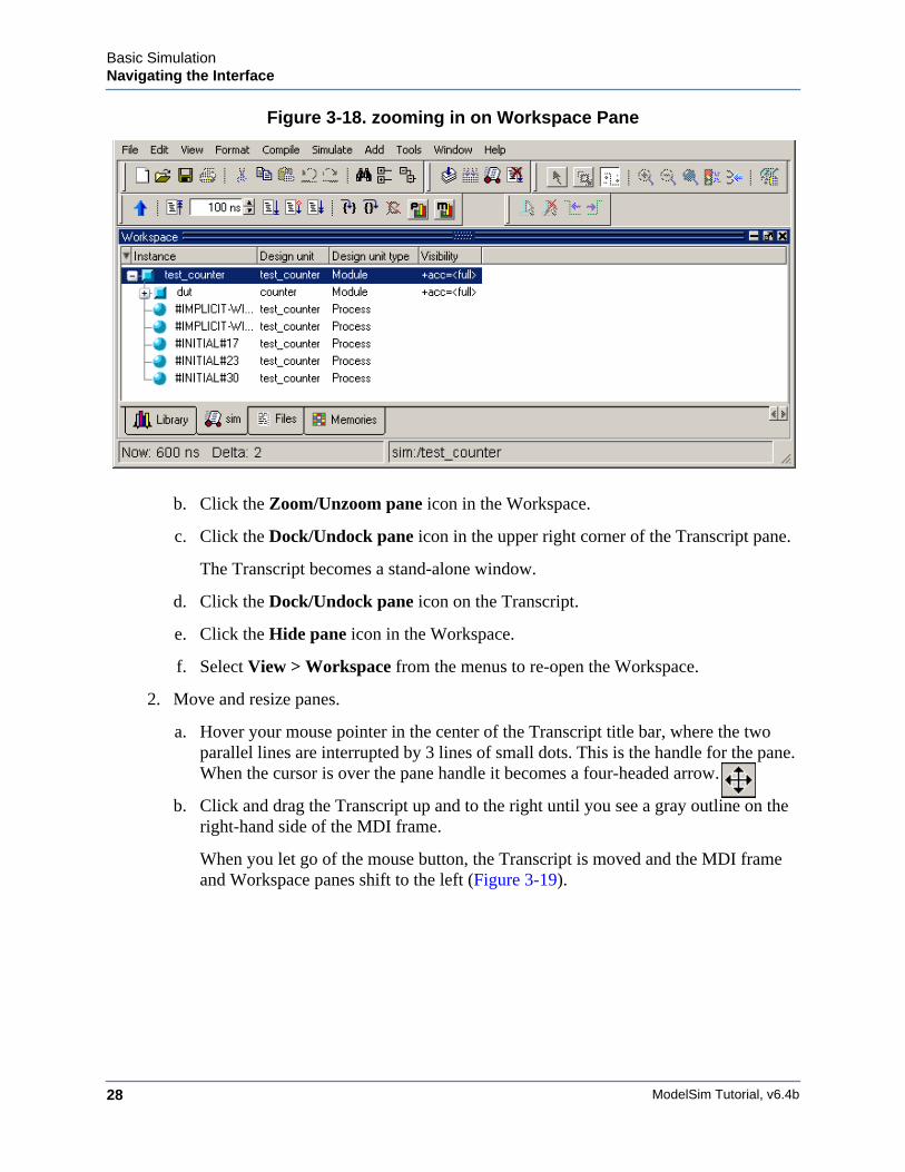
The pane fills the entire Main window (Figure 3-18).
MDI frame The Multiple Document Interface (MDI)frame holds windows for which there can bemultiple instances. These include Sourceeditor windows, Wave windows, and Memorycontent windows. Refer to the sectionMultiple Document Interface (MDI) Frame inthe User’s Manual for more information.
Table 3-1. The Main Window
Window/pane Description
ModelSim Tutorial, v6.4b28
Basic SimulationNavigating the Interface
Figure 3-18. zooming in on Workspace Pane
b. Click the Zoom/Unzoom pane icon in the Workspace.
c. Click the Dock/Undock pane icon in the upper right corner of the Transcript pane.
The Transcript becomes a stand-alone window.
d. Click the Dock/Undock pane icon on the Transcript.
e. Click the Hide pane icon in the Workspace.
f. Select View > Workspace from the menus to re-open the Workspace.
2. Move and resize panes.
a. Hover your mouse pointer in the center of the Transcript title bar, where the twoparallel lines are interrupted by 3 lines of small dots. This is the handle for the pane.When the cursor is over the pane handle it becomes a four-headed arrow.
b. Click and drag the Transcript up and to the right until you see a gray outline on theright-hand side of the MDI frame.
When you let go of the mouse button, the Transcript is moved and the MDI frameand Workspace panes shift to the left (Figure 3-19).
Basic SimulationNavigating the Interface
ModelSim Tutorial, v6.4b 29
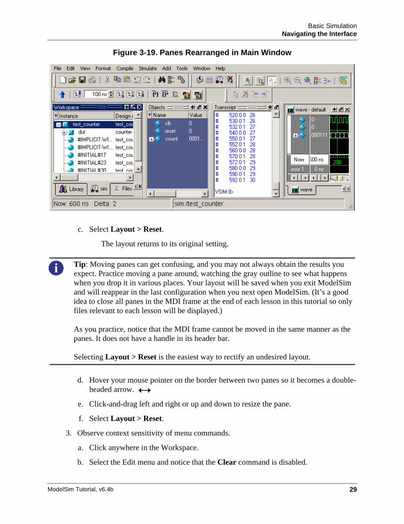
Figure 3-19. Panes Rearranged in Main Window
c. Select Layout > Reset.
The layout returns to its original setting.
Tip: Moving panes can get confusing, and you may not always obtain the results youexpect. Practice moving a pane around, watching the gray outline to see what happenswhen you drop it in various places. Your layout will be saved when you exit ModelSimand will reappear in the last configuration when you next open ModelSim. (It’s a goodidea to close all panes in the MDI frame at the end of each lesson in this tutorial so onlyfiles relevant to each lesson will be displayed.)
As you practice, notice that the MDI frame cannot be moved in the same manner as thepanes. It does not have a handle in its header bar.
Selecting Layout > Reset is the easiest way to rectify an undesired layout.
d. Hover your mouse pointer on the border between two panes so it becomes a double-headed arrow.
e. Click-and-drag left and right or up and down to resize the pane.
f. Select Layout > Reset.
3. Observe context sensitivity of menu commands.
a. Click anywhere in the Workspace.
b. Select the Edit menu and notice that the Clear command is disabled.
ModelSim Tutorial, v6.4b30
Basic SimulationNavigating the Interface
c. Click in the Transcript and select Edit > Clear.
This command applies to the Transcript pane but not the Workspace pane.
d. Click on a design object in the sim tab of the Workspace and select File > Open.
e. Notice that the Open dialog filters to show Log files (*.wlf).
f. Now click on a filename in the Files tab of the Workspace and select File > Open.
Notice that the Open dialog filters to show HDL file types instead.
Lesson Wrap-Up
This concludes this lesson. Before continuing we need to end the current simulation.
1. Select Simulate > End Simulation.
2. Click Yes when prompted to confirm that you wish to quit simulating.
ModelSim Tutorial, v6.4b 31
Chapter 4Projects
Introduction
In this lesson you will practice creating a project.
At a minimum, projects contain a work library and a session state that is stored in a .mpf file. Aproject may also consist of:
• HDL source files or references to source files
• other files such as READMEs or other project documentation
• local libraries
• references to global libraries
Design Files for this Lesson
The sample design for this lesson is a simple 8-bit, binary up-counter with an associatedtestbench. The pathnames are as follows:
Verilog – <install_dir>/examples/tutorials/verilog/projects/counter.v and tcounter.v
VHDL – <install_dir>/examples/tutorials/vhdl/projects/counter.vhd and tcounter.vhd
This lesson uses the Verilog files tcounter.v and counter.v. If you have a VHDL license, usetcounter.vhd and counter.vhd instead.
Related Reading
User’s Manual Chapter: Projects.
Create a New Project1. Create a new directory and copy the design files for this lesson into it.
Start by creating a new directory for this exercise (in case other users will be workingwith these lessons).
Verilog: Copy counter.v and tcounter.v files from/<install_dir>/examples/tutorials/verilog/projects to the new directory.
VHDL: Copy counter.vhd and tcounter.vhd files from/<install_dir>/examples/tutorials/vhdl/projects to the new directory.
ModelSim Tutorial, v6.4b32
ProjectsCreate a New Project
2. If you just finished the previous lesson, ModelSim should already be running. If not,start ModelSim.
a. Type vsim at a UNIX shell prompt or use the ModelSim icon in Windows.
b. Select File > Change Directory and change to the directory you created in step 1.
3. Create a new project.
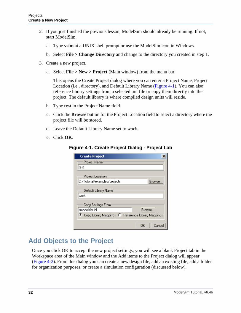
a. Select File > New > Project (Main window) from the menu bar.
This opens the Create Project dialog where you can enter a Project Name, ProjectLocation (i.e., directory), and Default Library Name (Figure 4-1). You can alsoreference library settings from a selected .ini file or copy them directly into theproject. The default library is where compiled design units will reside.
b. Type test in the Project Name field.
c. Click the Browse button for the Project Location field to select a directory where theproject file will be stored.
d. Leave the Default Library Name set to work.
e. Click OK.
Figure 4-1. Create Project Dialog - Project Lab
Add Objects to the ProjectOnce you click OK to accept the new project settings, you will see a blank Project tab in theWorkspace area of the Main window and the Add items to the Project dialog will appear(Figure 4-2). From this dialog you can create a new design file, add an existing file, add a folderfor organization purposes, or create a simulation configuration (discussed below).
ProjectsCreate a New Project
ModelSim Tutorial, v6.4b 33
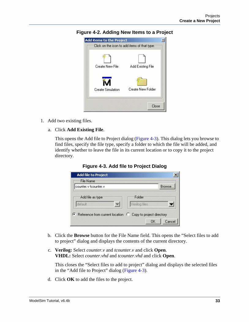
Figure 4-2. Adding New Items to a Project
1. Add two existing files.
a. Click Add Existing File.
This opens the Add file to Project dialog (Figure 4-3). This dialog lets you browse tofind files, specify the file type, specify a folder to which the file will be added, andidentify whether to leave the file in its current location or to copy it to the projectdirectory.
Figure 4-3. Add file to Project Dialog
b. Click the Browse button for the File Name field. This opens the “Select files to addto project” dialog and displays the contents of the current directory.
c. Verilog: Select counter.v and tcounter.v and click Open.VHDL: Select counter.vhd and tcounter.vhd and click Open.
This closes the “Select files to add to project” dialog and displays the selected filesin the “Add file to Project” dialog (Figure 4-3).
d. Click OK to add the files to the project.
ModelSim Tutorial, v6.4b34
ProjectsCreate a New Project
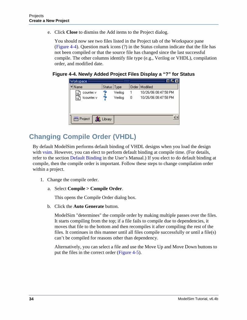
e. Click Close to dismiss the Add items to the Project dialog.
You should now see two files listed in the Project tab of the Workspace pane(Figure 4-4). Question mark icons (?) in the Status column indicate that the file hasnot been compiled or that the source file has changed since the last successfulcompile. The other columns identify file type (e.g., Verilog or VHDL), compilationorder, and modified date.
Figure 4-4. Newly Added Project Files Display a “?” for Status
Changing Compile Order (VHDL)By default ModelSim performs default binding of VHDL designs when you load the designwith vsim. However, you can elect to perform default binding at compile time. (For details,refer to the section Default Binding in the User’s Manual.) If you elect to do default binding atcompile, then the compile order is important. Follow these steps to change compilation orderwithin a project.
1. Change the compile order.
a. Select Compile > Compile Order.
This opens the Compile Order dialog box.
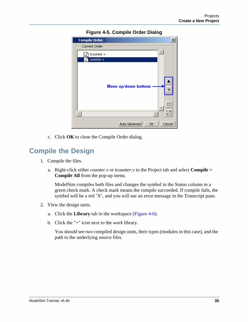
b. Click the Auto Generate button.
ModelSim "determines" the compile order by making multiple passes over the files.It starts compiling from the top; if a file fails to compile due to dependencies, itmoves that file to the bottom and then recompiles it after compiling the rest of thefiles. It continues in this manner until all files compile successfully or until a file(s)can’t be compiled for reasons other than dependency.
Alternatively, you can select a file and use the Move Up and Move Down buttons toput the files in the correct order (Figure 4-5).
ProjectsCreate a New Project
ModelSim Tutorial, v6.4b 35
Figure 4-5. Compile Order Dialog
c. Click OK to close the Compile Order dialog.
Compile the Design1. Compile the files.
a. Right-click either counter.v or tcounter.v in the Project tab and select Compile >Compile All from the pop-up menu.
ModelSim compiles both files and changes the symbol in the Status column to agreen check mark. A check mark means the compile succeeded. If compile fails, thesymbol will be a red ’X’, and you will see an error message in the Transcript pane.
2. View the design units.
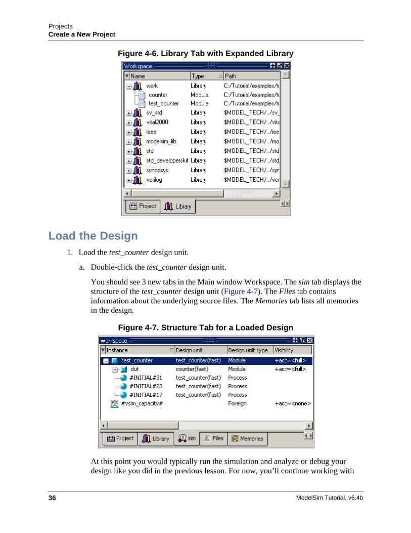
a. Click the Library tab in the workspace (Figure 4-6).
b. Click the "+" icon next to the work library.
You should see two compiled design units, their types (modules in this case), and thepath to the underlying source files.
ModelSim Tutorial, v6.4b36
ProjectsCreate a New Project
Figure 4-6. Library Tab with Expanded Library
Load the Design1. Load the test_counter design unit.
a. Double-click the test_counter design unit.
You should see 3 new tabs in the Main window Workspace. The sim tab displays thestructure of the test_counter design unit (Figure 4-7). The Files tab containsinformation about the underlying source files. The Memories tab lists all memoriesin the design.
Figure 4-7. Structure Tab for a Loaded Design
At this point you would typically run the simulation and analyze or debug yourdesign like you did in the previous lesson. For now, you’ll continue working with
ProjectsOrganizing Projects with Folders
ModelSim Tutorial, v6.4b 37
the project. However, first you need to end the simulation that started when youloaded test_counter.
2. End the simulation.
a. Select Simulate > End Simulation.
b. Click Yes.
Organizing Projects with FoldersIf you have a lot of files to add to a project, you may want to organize them in folders. You cancreate folders either before or after adding your files. If you create a folder before adding files,you can specify in which folder you want a file placed at the time you add the file (see Folderfield in Figure 4-3). If you create a folder after adding files, you edit the file properties to moveit to that folder.
Add FoldersAs shown previously in Figure 4-2, the Add items to the Project dialog has an option for addingfolders. If you have already closed that dialog, you can use a menu command to add a folder.
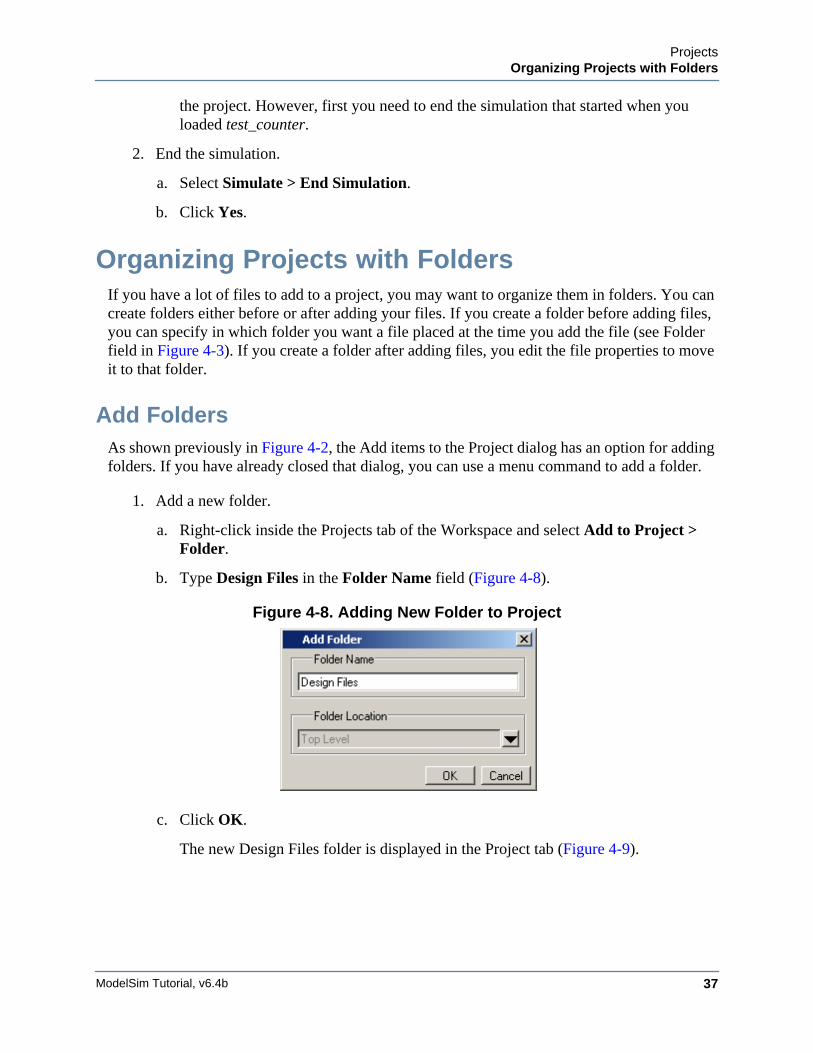
1. Add a new folder.
a. Right-click inside the Projects tab of the Workspace and select Add to Project >Folder.
b. Type Design Files in the Folder Name field (Figure 4-8).
Figure 4-8. Adding New Folder to Project
c. Click OK.
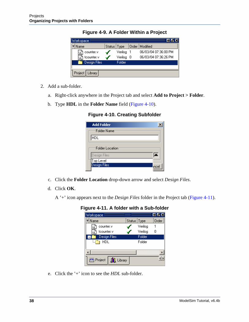
The new Design Files folder is displayed in the Project tab (Figure 4-9).
ModelSim Tutorial, v6.4b38
ProjectsOrganizing Projects with Folders
Figure 4-9. A Folder Within a Project
2. Add a sub-folder.
a. Right-click anywhere in the Project tab and select Add to Project > Folder.
b. Type HDL in the Folder Name field (Figure 4-10).
Figure 4-10. Creating Subfolder
c. Click the Folder Location drop-down arrow and select Design Files.
d. Click OK.
A ’+’ icon appears next to the Design Files folder in the Project tab (Figure 4-11).
Figure 4-11. A folder with a Sub-folder
e. Click the ’+’ icon to see the HDL sub-folder.
ProjectsSimulation Configurations
ModelSim Tutorial, v6.4b 39
Moving Files to FoldersIf you don’t place files into a folder when you first add the files to the project, you can movethem into a folder using the properties dialog.
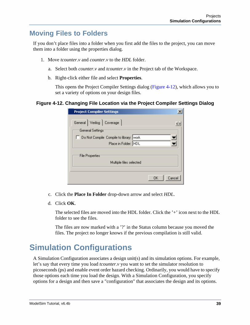
1. Move tcounter.v and counter.v to the HDL folder.
a. Select both counter.v and tcounter.v in the Project tab of the Workspace.
b. Right-click either file and select Properties.
This opens the Project Compiler Settings dialog (Figure 4-12), which allows you toset a variety of options on your design files.
Figure 4-12. Changing File Location via the Project Compiler Settings Dialog
c. Click the Place In Folder drop-down arrow and select HDL.
d. Click OK.
The selected files are moved into the HDL folder. Click the ’+’ icon next to the HDLfolder to see the files.
The files are now marked with a ’?’ in the Status column because you moved thefiles. The project no longer knows if the previous compilation is still valid.
Simulation ConfigurationsA Simulation Configuration associates a design unit(s) and its simulation options. For example,let’s say that every time you load tcounter.v you want to set the simulator resolution topicoseconds (ps) and enable event order hazard checking. Ordinarily, you would have to specifythose options each time you load the design. With a Simulation Configuration, you specifyoptions for a design and then save a "configuration" that associates the design and its options.
ModelSim Tutorial, v6.4b40
ProjectsSimulation Configurations
The configuration is then listed in the Project tab and you can double-click it to load tcounter.valong with its options.
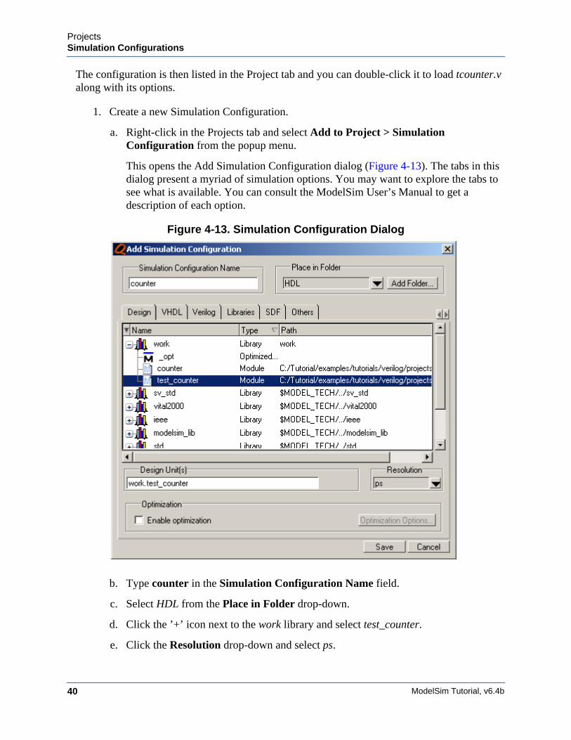
1. Create a new Simulation Configuration.
a. Right-click in the Projects tab and select Add to Project > SimulationConfiguration from the popup menu.
This opens the Add Simulation Configuration dialog (Figure 4-13). The tabs in thisdialog present a myriad of simulation options. You may want to explore the tabs tosee what is available. You can consult the ModelSim User’s Manual to get adescription of each option.
Figure 4-13. Simulation Configuration Dialog
b. Type counter in the Simulation Configuration Name field.
c. Select HDL from the Place in Folder drop-down.
d. Click the ’+’ icon next to the work library and select test_counter.
e. Click the Resolution drop-down and select ps.
ProjectsSimulation Configurations
ModelSim Tutorial, v6.4b 41
f. For Verilog, click the Verilog tab and check Enable hazard checking (-hazards).
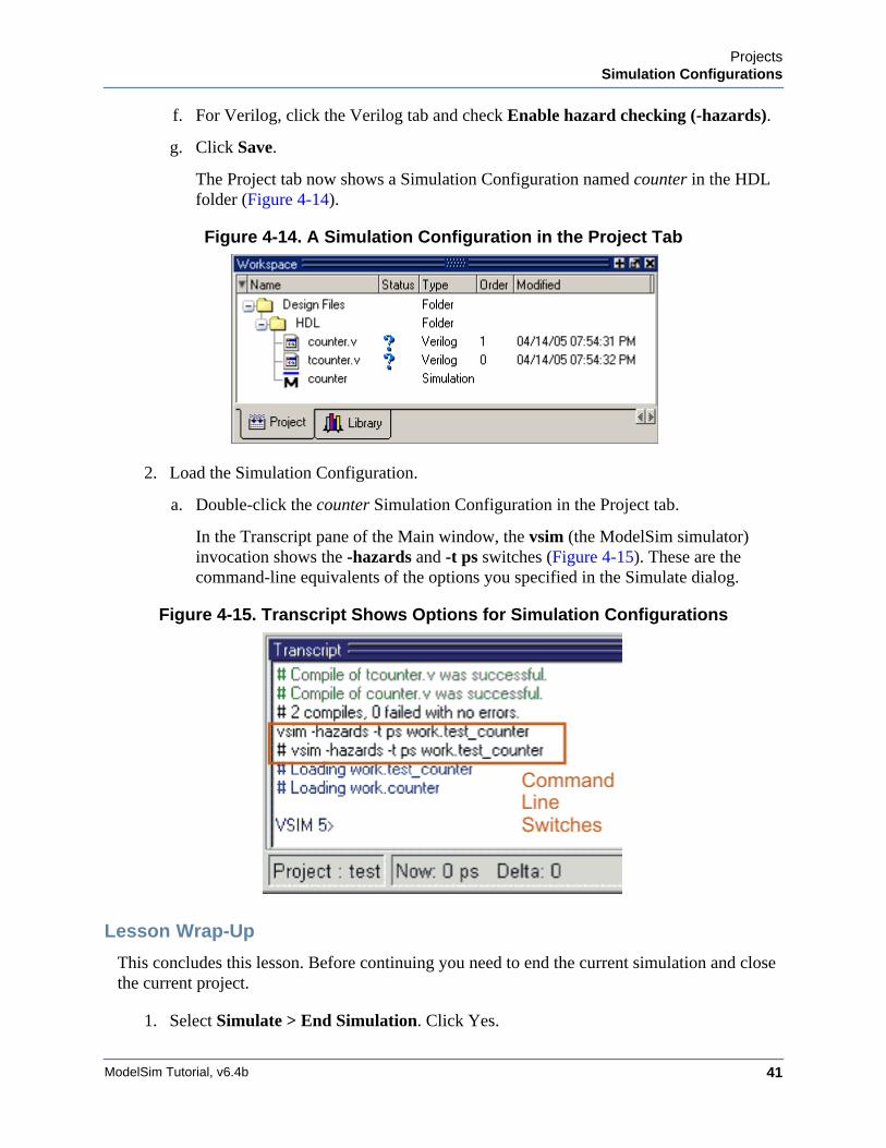
g. Click Save.
The Project tab now shows a Simulation Configuration named counter in the HDLfolder (Figure 4-14).
Figure 4-14. A Simulation Configuration in the Project Tab
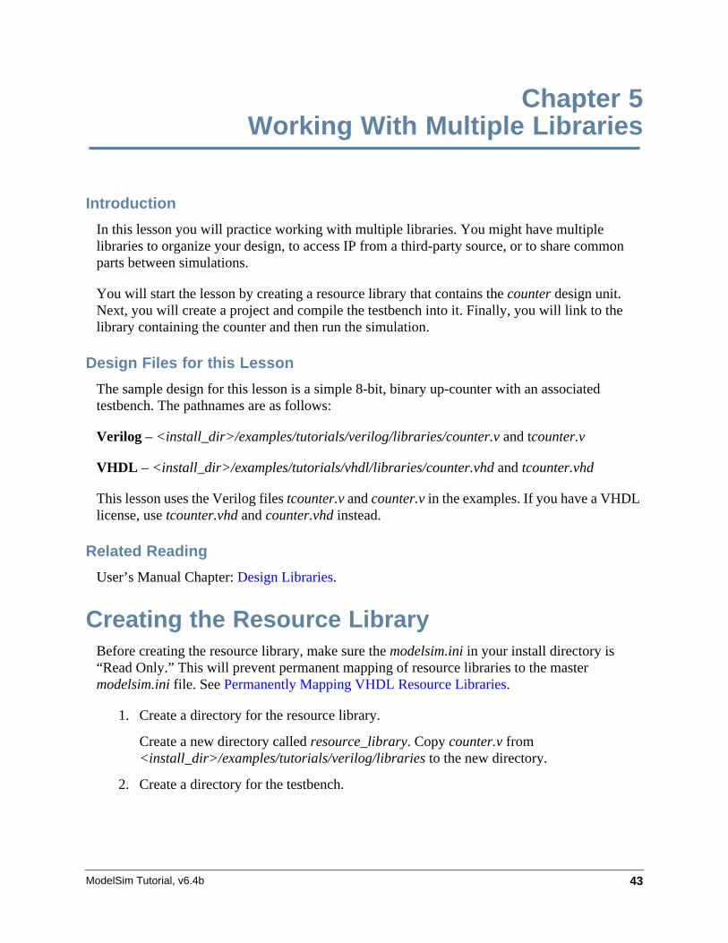
2. Load the Simulation Configuration.
a. Double-click the counter Simulation Configuration in the Project tab.
In the Transcript pane of the Main window, the vsim (the ModelSim simulator)invocation shows the -hazards and -t ps switches (Figure 4-15). These are thecommand-line equivalents of the options you specified in the Simulate dialog.
Figure 4-15. Transcript Shows Options for Simulation Configurations
Lesson Wrap-Up
This concludes this lesson. Before continuing you need to end the current simulation and closethe current project.
1. Select Simulate > End Simulation. Click Yes.

ModelSim Tutorial, v6.4b42
ProjectsSimulation Configurations
2. Select the Project tab in the Main window Workspace.
3. Right-click in this tab to open a popup menu and select Close Project.
4. Click OK.
If you do not close the project, it will open automatically the next time you startModelSim.
ModelSim Tutorial, v6.4b 43
Chapter 5Working With Multiple Libraries
Introduction
In this lesson you will practice working with multiple libraries. You might have multiplelibraries to organize your design, to access IP from a third-party source, or to share commonparts between simulations.
You will start the lesson by creating a resource library that contains the counter design unit.Next, you will create a project and compile the testbench into it. Finally, you will link to thelibrary containing the counter and then run the simulation.
Design Files for this Lesson
The sample design for this lesson is a simple 8-bit, binary up-counter with an associatedtestbench. The pathnames are as follows:
Verilog – <install_dir>/examples/tutorials/verilog/libraries/counter.v and tcounter.v
VHDL – <install_dir>/examples/tutorials/vhdl/libraries/counter.vhd and tcounter.vhd
This lesson uses the Verilog files tcounter.v and counter.v in the examples. If you have a VHDLlicense, use tcounter.vhd and counter.vhd instead.
Related Reading
User’s Manual Chapter: Design Libraries.
Creating the Resource LibraryBefore creating the resource library, make sure the modelsim.ini in your install directory is“Read Only.” This will prevent permanent mapping of resource libraries to the mastermodelsim.ini file. See Permanently Mapping VHDL Resource Libraries.
1. Create a directory for the resource library.
Create a new directory called resource_library. Copy counter.v from<install_dir>/examples/tutorials/verilog/libraries to the new directory.
2. Create a directory for the testbench.
ModelSim Tutorial, v6.4b44
Working With Multiple LibrariesCreating the Resource Library
Create a new directory called testbench that will hold the testbench and project files.Copy tcounter.v from <install_dir>/examples/tutorials/verilog/libraries to the newdirectory.
You are creating two directories in this lesson to mimic the situation where you receivea resource library from a third-party. As noted earlier, we will link to the resourcelibrary in the first directory later in the lesson.
3. Start ModelSim and change to the resource_library directory.
If you just finished the previous lesson, ModelSim should already be running. If not,start ModelSim.
a. Type vsim at a UNIX shell prompt or use the ModelSim icon in Windows.
If the Welcome to ModelSim dialog appears, click Close.
b. Select File > Change Directory and change to the resource_library directory youcreated in step 1.
4. Create the resource library.
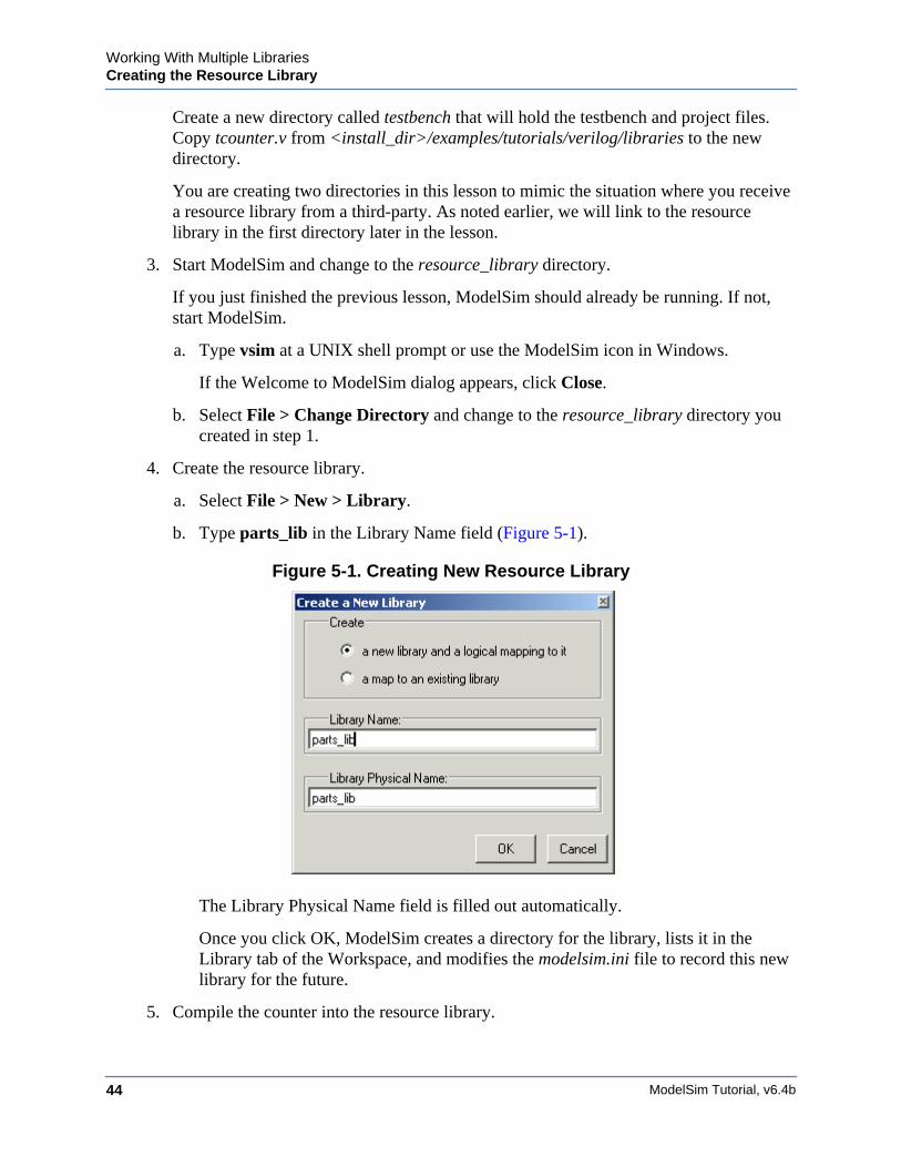
a. Select File > New > Library.
b. Type parts_lib in the Library Name field (Figure 5-1).
Figure 5-1. Creating New Resource Library
The Library Physical Name field is filled out automatically.
Once you click OK, ModelSim creates a directory for the library, lists it in theLibrary tab of the Workspace, and modifies the modelsim.ini file to record this newlibrary for the future.
5. Compile the counter into the resource library.
Working With Multiple LibrariesCreating the Project
ModelSim Tutorial, v6.4b 45
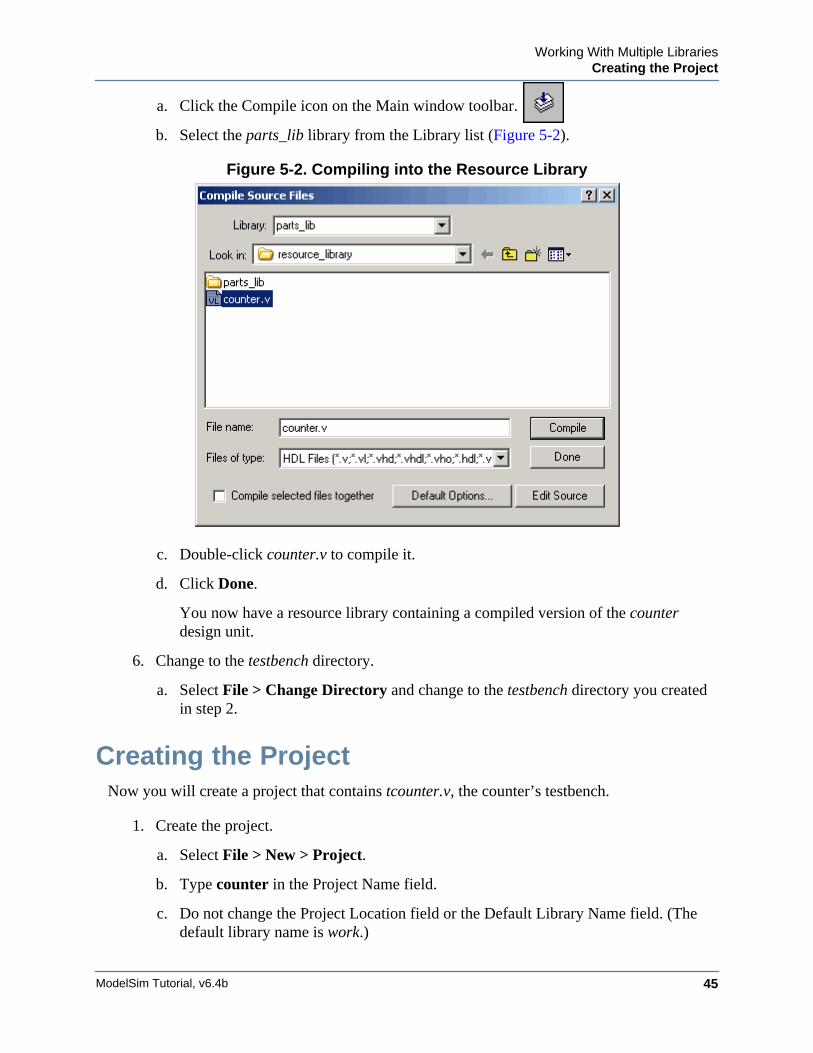
a. Click the Compile icon on the Main window toolbar.
b. Select the parts_lib library from the Library list (Figure 5-2).
Figure 5-2. Compiling into the Resource Library
c. Double-click counter.v to compile it.
d. Click Done.
You now have a resource library containing a compiled version of the counterdesign unit.
6. Change to the testbench directory.
a. Select File > Change Directory and change to the testbench directory you createdin step 2.
Creating the ProjectNow you will create a project that contains tcounter.v, the counter’s testbench.
1. Create the project.
a. Select File > New > Project.
b. Type counter in the Project Name field.
c. Do not change the Project Location field or the Default Library Name field. (Thedefault library name is work.)
ModelSim Tutorial, v6.4b46
Working With Multiple LibrariesLinking to the Resource Library
d. Make sure “Copy Library Mappings” is selected. The default modelsim.ini file willbe used.
e. Click OK.
2. Add the testbench to the project.
a. Click Add Existing File in the Add items to the Project dialog.
b. Click the Browse button and select tcounter.v in the “Select files to add to project”dialog.
c. Click Open.
d. Click OK.
e. Click Close to dismiss the “Add items to the Project” dialog.
The tcounter.v file is listed in the Project tab of the Main window.
3. Compile the testbench.
a. Right-click tcounter.v and select Compile > Compile Selected.
Linking to the Resource LibraryTo wrap up this part of the lesson, you will link to the parts_lib library you created earlier. Butfirst, try simulating the testbench without the link and see what happens.
ModelSim responds differently for Verilog and VHDL in this situation.
Verilog
1. Simulate a Verilog design with a missing resource library.
a. In the Library tab, click the ’+’ icon next to the work library and double-clicktest_counter.
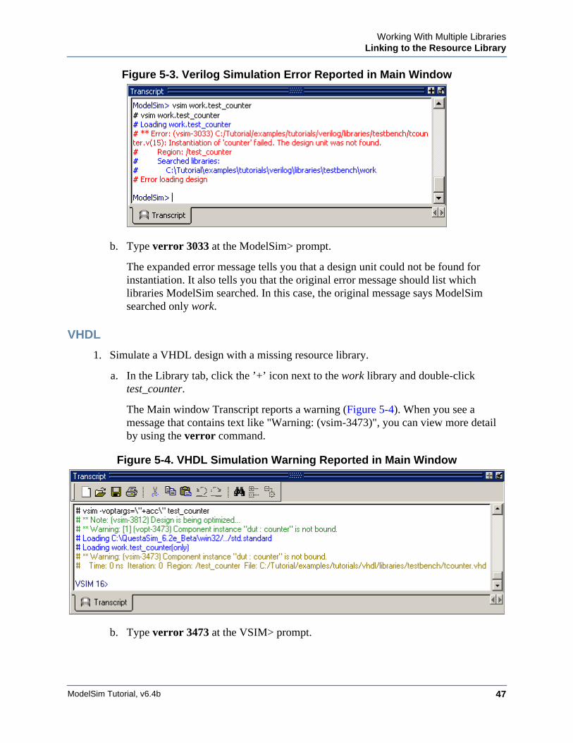
The Main window Transcript reports an error (Figure 5-3). When you see a messagethat contains text like "Error: (vsim-3033)", you can view more detail by using theverror command.
Working With Multiple LibrariesLinking to the Resource Library
ModelSim Tutorial, v6.4b 47
Figure 5-3. Verilog Simulation Error Reported in Main Window
b. Type verror 3033 at the ModelSim> prompt.
The expanded error message tells you that a design unit could not be found forinstantiation. It also tells you that the original error message should list whichlibraries ModelSim searched. In this case, the original message says ModelSimsearched only work.
VHDL
1. Simulate a VHDL design with a missing resource library.
a. In the Library tab, click the ’+’ icon next to the work library and double-clicktest_counter.
The Main window Transcript reports a warning (Figure 5-4). When you see amessage that contains text like "Warning: (vsim-3473)", you can view more detailby using the verror command.
Figure 5-4. VHDL Simulation Warning Reported in Main Window
b. Type verror 3473 at the VSIM> prompt.
ModelSim Tutorial, v6.4b48
Working With Multiple LibrariesLinking to the Resource Library
The expanded error message tells you that a component (’dut’ in this case) has notbeen explicitly bound and no default binding can be found.
c. Type quit -sim to quit the simulation.
The process for linking to a resource library differs between Verilog and VHDL. If you areusing Verilog, follow the steps in Linking in Verilog. If you are using VHDL, follow the stepsin Linking in VHDL one page later.
Linking in VerilogLinking in Verilog requires that you specify a "search library" when you invoke the simulator.
1. Specify a search library during simulation.
a. Click the Simulate icon on the Main window toolbar.
b. Click the ’+’ icon next to the work library and select test_counter.
c. Click the Libraries tab.
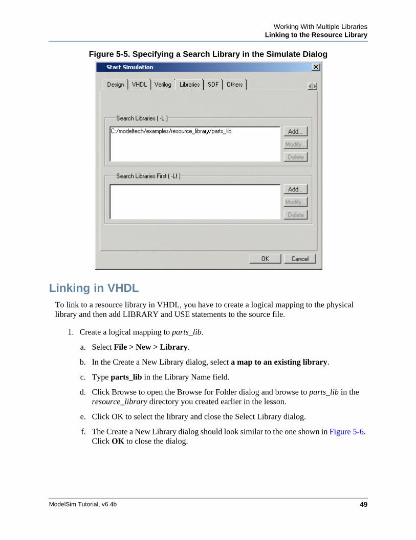
d. Click the Add button next to the Search Libraries field and browse to parts_lib in theresource_library directory you created earlier in the lesson.
e. Click OK.
The dialog should have parts_lib listed in the Search Libraries field (Figure 5-5).
f. Click OK.
The design loads without errors.
Working With Multiple LibrariesLinking to the Resource Library
ModelSim Tutorial, v6.4b 49
Figure 5-5. Specifying a Search Library in the Simulate Dialog
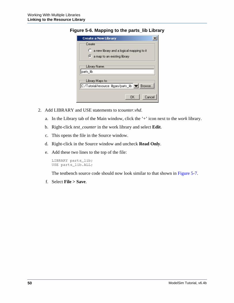
Linking in VHDLTo link to a resource library in VHDL, you have to create a logical mapping to the physicallibrary and then add LIBRARY and USE statements to the source file.
1. Create a logical mapping to parts_lib.
a. Select File > New > Library.
b. In the Create a New Library dialog, select a map to an existing library.
c. Type parts_lib in the Library Name field.
d. Click Browse to open the Browse for Folder dialog and browse to parts_lib in theresource_library directory you created earlier in the lesson.
e. Click OK to select the library and close the Select Library dialog.
f. The Create a New Library dialog should look similar to the one shown in Figure 5-6.Click OK to close the dialog.
ModelSim Tutorial, v6.4b50
Working With Multiple LibrariesLinking to the Resource Library
Figure 5-6. Mapping to the parts_lib Library
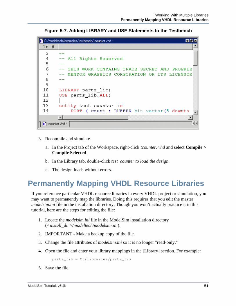
2. Add LIBRARY and USE statements to tcounter.vhd.
a. In the Library tab of the Main window, click the ’+’ icon next to the work library.
b. Right-click test_counter in the work library and select Edit.
c. This opens the file in the Source window.
d. Right-click in the Source window and uncheck Read Only.
e. Add these two lines to the top of the file:
LIBRARY parts_lib;USE parts_lib.ALL;
The testbench source code should now look similar to that shown in Figure 5-7.
f. Select File > Save.
Working With Multiple LibrariesPermanently Mapping VHDL Resource Libraries
ModelSim Tutorial, v6.4b 51
Figure 5-7. Adding LIBRARY and USE Statements to the Testbench
3. Recompile and simulate.
a. In the Project tab of the Workspace, right-click tcounter. vhd and select Compile >Compile Selected.
b. In the Library tab, double-click test_counter to load the design.
c. The design loads without errors.
Permanently Mapping VHDL Resource LibrariesIf you reference particular VHDL resource libraries in every VHDL project or simulation, youmay want to permanently map the libraries. Doing this requires that you edit the mastermodelsim.ini file in the installation directory. Though you won’t actually practice it in thistutorial, here are the steps for editing the file:
1. Locate the modelsim.ini file in the ModelSim installation directory(<install_dir>/modeltech/modelsim.ini).
2. IMPORTANT - Make a backup copy of the file.
3. Change the file attributes of modelsim.ini so it is no longer "read-only."
4. Open the file and enter your library mappings in the [Library] section. For example:
parts_lib = C:/libraries/parts_lib
5. Save the file.

ModelSim Tutorial, v6.4b52
Working With Multiple LibrariesPermanently Mapping VHDL Resource Libraries
6. Change the file attributes so the file is "read-only" again.
Lesson Wrap-Up
This concludes this lesson. Before continuing we need to end the current simulation and closethe project.
1. Select Simulate > End Simulation. Click Yes.
2. Select the Project tab of the Main window Workspace.
3. Select File > Close. Click OK.
ModelSim Tutorial, v6.4b 53
Chapter 6Analyzing Waveforms
Introduction
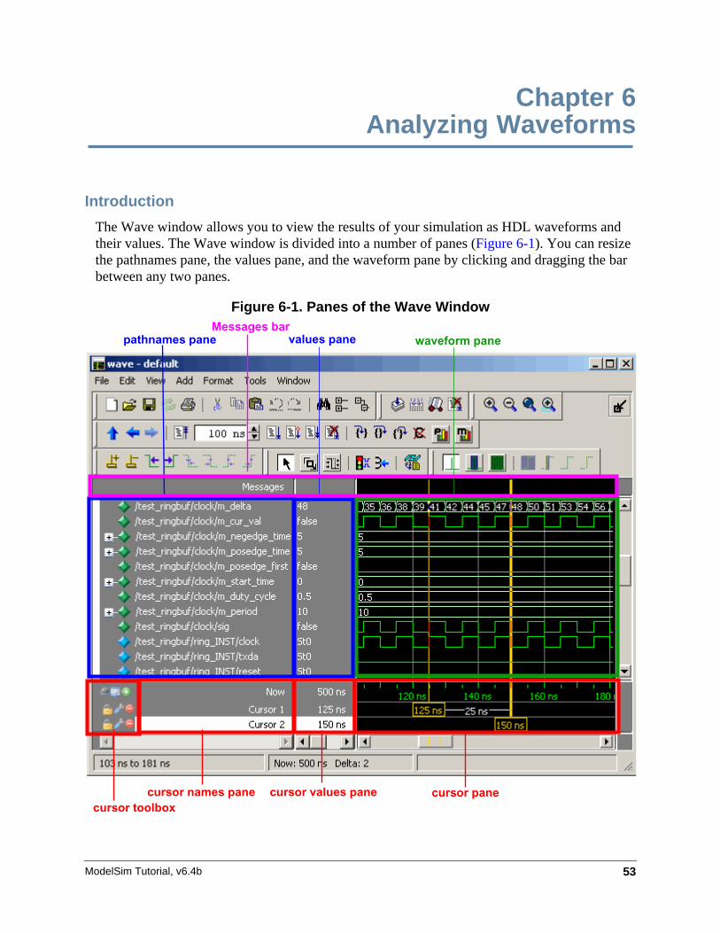
The Wave window allows you to view the results of your simulation as HDL waveforms andtheir values. The Wave window is divided into a number of panes (Figure 6-1). You can resizethe pathnames pane, the values pane, and the waveform pane by clicking and dragging the barbetween any two panes.
Figure 6-1. Panes of the Wave Window
waveform pane
cursor pane
values panepathnames pane
cursor names pane cursor values panecursor toolbox
Messages bar
ModelSim Tutorial, v6.4b54
Analyzing WaveformsLoading a Design
Related Reading
User’s Manual sections: Wave Window and Recording Simulation Results With Datasets
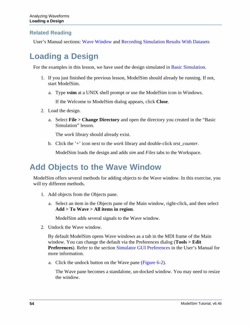
Loading a DesignFor the examples in this lesson, we have used the design simulated in Basic Simulation.
1. If you just finished the previous lesson, ModelSim should already be running. If not,start ModelSim.
a. Type vsim at a UNIX shell prompt or use the ModelSim icon in Windows.
If the Welcome to ModelSim dialog appears, click Close.
2. Load the design.
a. Select File > Change Directory and open the directory you created in the “BasicSimulation” lesson.
The work library should already exist.
b. Click the ’+’ icon next to the work library and double-click test_counter.
ModelSim loads the design and adds sim and Files tabs to the Workspace.
Add Objects to the Wave WindowModelSim offers several methods for adding objects to the Wave window. In this exercise, youwill try different methods.
1. Add objects from the Objects pane.
a. Select an item in the Objects pane of the Main window, right-click, and then selectAdd > To Wave > All items in region.
ModelSim adds several signals to the Wave window.
2. Undock the Wave window.
By default ModelSim opens Wave windows as a tab in the MDI frame of the Mainwindow. You can change the default via the Preferences dialog (Tools > EditPreferences). Refer to the section Simulator GUI Preferences in the User’s Manual formore information.
a. Click the undock button on the Wave pane (Figure 6-2).
The Wave pane becomes a standalone, un-docked window. You may need to resizethe window.
Analyzing WaveformsZooming the Waveform Display
ModelSim Tutorial, v6.4b 55
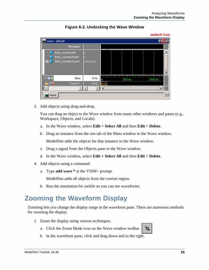
Figure 6-2. Undocking the Wave Window
3. Add objects using drag-and-drop.
You can drag an object to the Wave window from many other windows and panes (e.g.,Workspace, Objects, and Locals).
a. In the Wave window, select Edit > Select All and then Edit > Delete.
b. Drag an instance from the sim tab of the Main window to the Wave window.
ModelSim adds the objects for that instance to the Wave window.
c. Drag a signal from the Objects pane to the Wave window.
d. In the Wave window, select Edit > Select All and then Edit > Delete.
4. Add objects using a command.
a. Type add wave * at the VSIM> prompt.
ModelSim adds all objects from the current region.
b. Run the simulation for awhile so you can see waveforms.
Zooming the Waveform DisplayZooming lets you change the display range in the waveform pane. There are numerous methodsfor zooming the display.
1. Zoom the display using various techniques.
a. Click the Zoom Mode icon on the Wave window toolbar.
b. In the waveform pane, click and drag down and to the right.
ModelSim Tutorial, v6.4b56
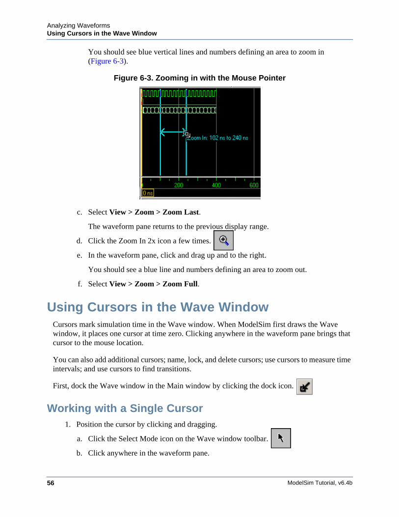
Analyzing WaveformsUsing Cursors in the Wave Window
You should see blue vertical lines and numbers defining an area to zoom in(Figure 6-3).
Figure 6-3. Zooming in with the Mouse Pointer
c. Select View > Zoom > Zoom Last.
The waveform pane returns to the previous display range.
d. Click the Zoom In 2x icon a few times.
e. In the waveform pane, click and drag up and to the right.
You should see a blue line and numbers defining an area to zoom out.
f. Select View > Zoom > Zoom Full.
Using Cursors in the Wave WindowCursors mark simulation time in the Wave window. When ModelSim first draws the Wavewindow, it places one cursor at time zero. Clicking anywhere in the waveform pane brings thatcursor to the mouse location.
You can also add additional cursors; name, lock, and delete cursors; use cursors to measure timeintervals; and use cursors to find transitions.
First, dock the Wave window in the Main window by clicking the dock icon.
Working with a Single Cursor1. Position the cursor by clicking and dragging.
a. Click the Select Mode icon on the Wave window toolbar.
b. Click anywhere in the waveform pane.
Analyzing WaveformsUsing Cursors in the Wave Window
ModelSim Tutorial, v6.4b 57
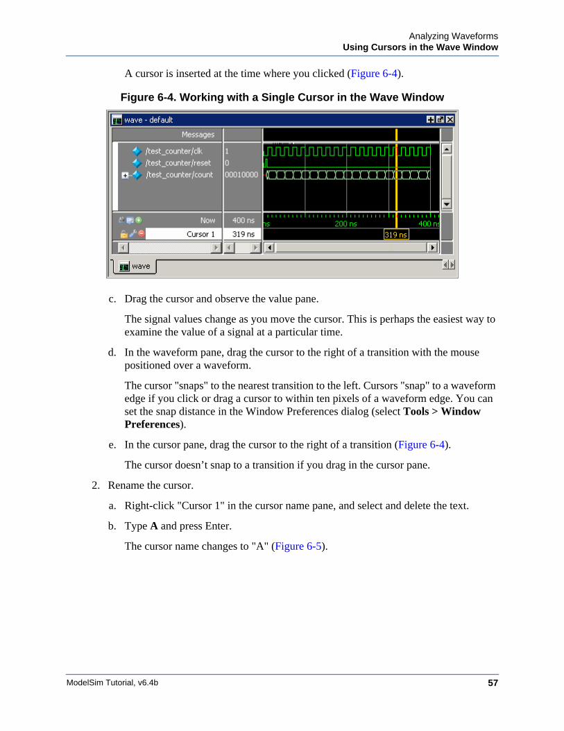
A cursor is inserted at the time where you clicked (Figure 6-4).
Figure 6-4. Working with a Single Cursor in the Wave Window
c. Drag the cursor and observe the value pane.
The signal values change as you move the cursor. This is perhaps the easiest way toexamine the value of a signal at a particular time.
d. In the waveform pane, drag the cursor to the right of a transition with the mousepositioned over a waveform.
The cursor "snaps" to the nearest transition to the left. Cursors "snap" to a waveformedge if you click or drag a cursor to within ten pixels of a waveform edge. You canset the snap distance in the Window Preferences dialog (select Tools > WindowPreferences).
e. In the cursor pane, drag the cursor to the right of a transition (Figure 6-4).
The cursor doesn’t snap to a transition if you drag in the cursor pane.
2. Rename the cursor.
a. Right-click "Cursor 1" in the cursor name pane, and select and delete the text.
b. Type A and press Enter.
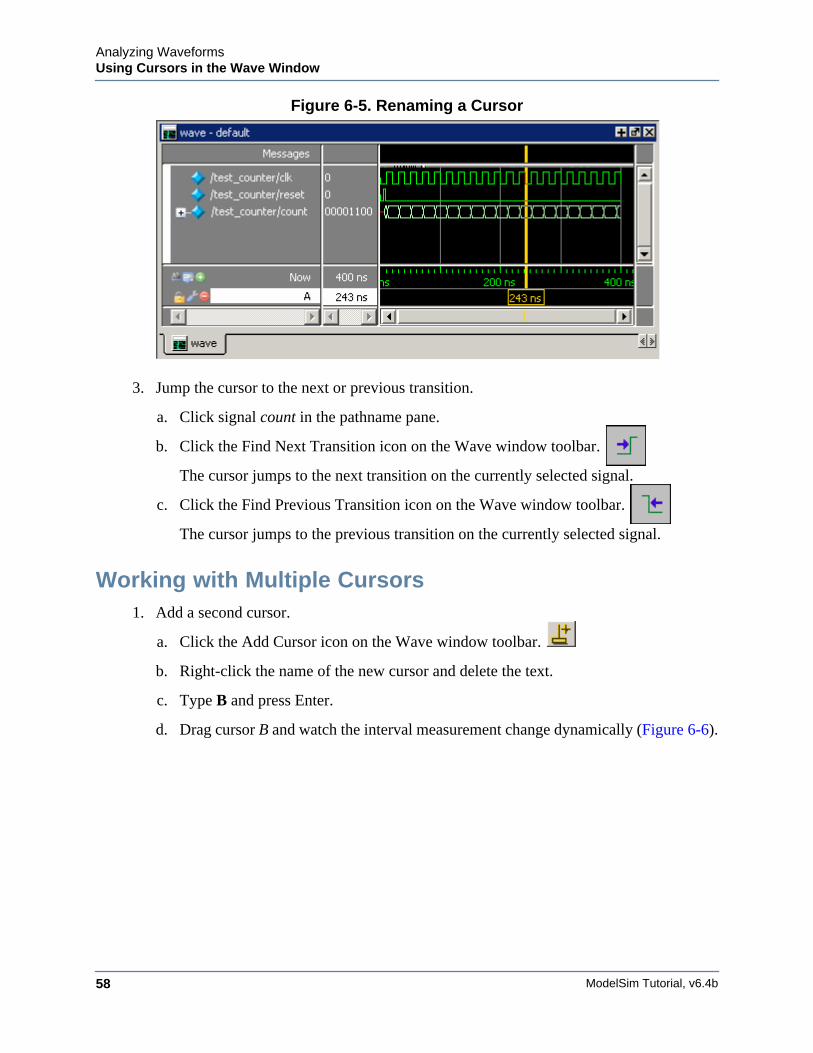
The cursor name changes to "A" (Figure 6-5).
ModelSim Tutorial, v6.4b58
Analyzing WaveformsUsing Cursors in the Wave Window
Figure 6-5. Renaming a Cursor
3. Jump the cursor to the next or previous transition.
a. Click signal count in the pathname pane.
b. Click the Find Next Transition icon on the Wave window toolbar.
The cursor jumps to the next transition on the currently selected signal.
c. Click the Find Previous Transition icon on the Wave window toolbar.
The cursor jumps to the previous transition on the currently selected signal.
Working with Multiple Cursors1. Add a second cursor.
a. Click the Add Cursor icon on the Wave window toolbar.
b. Right-click the name of the new cursor and delete the text.
c. Type B and press Enter.
d. Drag cursor B and watch the interval measurement change dynamically (Figure 6-6).
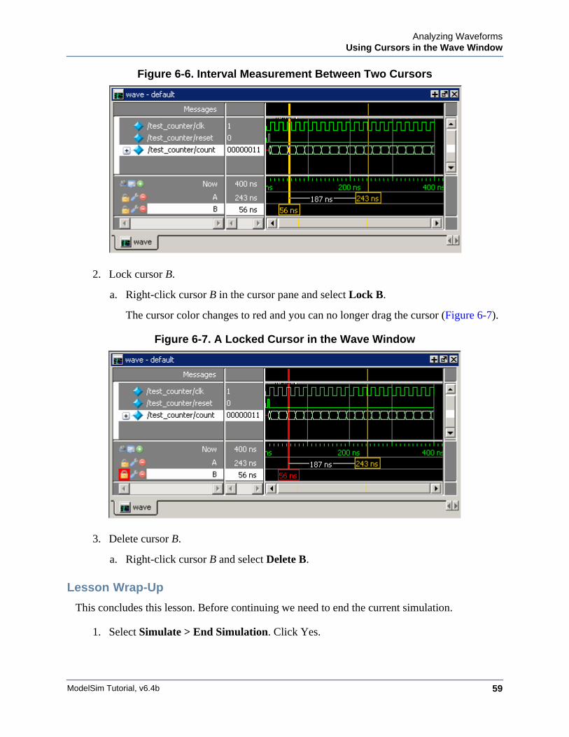
Analyzing WaveformsUsing Cursors in the Wave Window
ModelSim Tutorial, v6.4b 59
Figure 6-6. Interval Measurement Between Two Cursors
2. Lock cursor B.
a. Right-click cursor B in the cursor pane and select Lock B.
The cursor color changes to red and you can no longer drag the cursor (Figure 6-7).
Figure 6-7. A Locked Cursor in the Wave Window
3. Delete cursor B.
a. Right-click cursor B and select Delete B.
Lesson Wrap-Up
This concludes this lesson. Before continuing we need to end the current simulation.
1. Select Simulate > End Simulation. Click Yes.

ModelSim Tutorial, v6.4b60
Analyzing WaveformsUsing Cursors in the Wave Window
ModelSim Tutorial, v6.4b 61
Chapter 7Viewing And Initializing Memories
Introduction
In this lesson you will learn how to view and initialize memories in . defines and lists asmemories any of the following:
• reg, wire, and std_logic arrays
• Integer arrays
• Single dimensional arrays of VHDL enumerated types other than std_logic
Design Files for this Lesson
The installation comes with Verilog and VHDL versions of the example design. The files arelocated in the following directories:
This lesson uses the Verilog version for the exercises. If you have a VHDL license, use theVHDL version instead.
Related Reading
User’s Manual Section: Memory Panes.
Reference Manul commands: mem display, mem load, mem save, and radix.
Compile and Load the Design
1. Create a new directory and copy the tutorial files into it.
Start by creating a new directory for this exercise (in case other users will be workingwith these lessons). Create the directory and copy all files from<install_dir>/examples/tutorials/verilog/memory to the new directory.
If you have a VHDL license, copy the files in<install_dir>/examples/tutorials/vhdl/memory instead.
2. Start ModelSim and change to the exercise directory.
If you just finished the previous lesson, ModelSim should already be running. If not,start ModelSim.
a. Type vsim at a UNIX shell prompt or use the ModelSim icon in Windows.
If the Welcome to ModelSim dialog appears, click Close.
ModelSim Tutorial, v6.4b62
Viewing And Initializing MemoriesView a Memory and its Contents
b. Select File > Change Directory and change to the directory you created in step 1.
3. Create the working library and compile the design.
a. Type vlib work at the ModelSim> prompt.
b. Verilog:Type vlog sp_syn_ram.v dp_syn_ram.v ram_tb.v at the ModelSim> prompt.
VHDL:Type vcom -93 sp_syn_ram.vhd dp_syn_ram.vhd ram_tb.vhd at the ModelSim>prompt.
4. Load the design.
a. On the Library tab of the Main window Workspace, click the "+" icon next to thework library.
b. Double-click the ram_tb design unit to load the design.
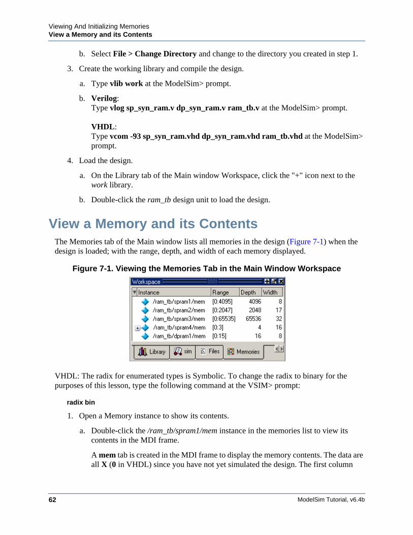
View a Memory and its ContentsThe Memories tab of the Main window lists all memories in the design (Figure 7-1) when thedesign is loaded; with the range, depth, and width of each memory displayed.
Figure 7-1. Viewing the Memories Tab in the Main Window Workspace
VHDL: The radix for enumerated types is Symbolic. To change the radix to binary for thepurposes of this lesson, type the following command at the VSIM> prompt:
radix bin
1. Open a Memory instance to show its contents.
a. Double-click the /ram_tb/spram1/mem instance in the memories list to view itscontents in the MDI frame.
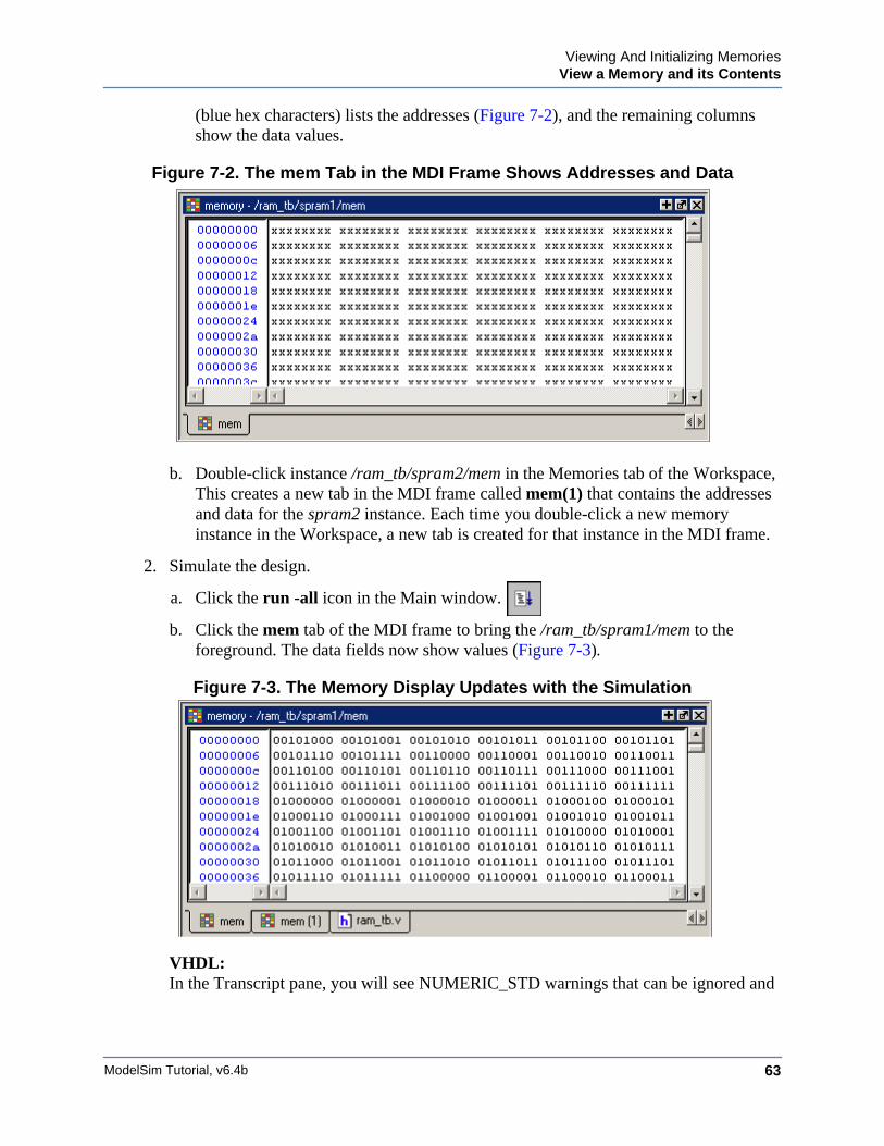
A mem tab is created in the MDI frame to display the memory contents. The data areall X (0 in VHDL) since you have not yet simulated the design. The first column
Viewing And Initializing MemoriesView a Memory and its Contents
ModelSim Tutorial, v6.4b 63
(blue hex characters) lists the addresses (Figure 7-2), and the remaining columnsshow the data values.
Figure 7-2. The mem Tab in the MDI Frame Shows Addresses and Data
b. Double-click instance /ram_tb/spram2/mem in the Memories tab of the Workspace,This creates a new tab in the MDI frame called mem(1) that contains the addressesand data for the spram2 instance. Each time you double-click a new memoryinstance in the Workspace, a new tab is created for that instance in the MDI frame.
2. Simulate the design.
a. Click the run -all icon in the Main window.
b. Click the mem tab of the MDI frame to bring the /ram_tb/spram1/mem to theforeground. The data fields now show values (Figure 7-3).
Figure 7-3. The Memory Display Updates with the Simulation
VHDL:In the Transcript pane, you will see NUMERIC_STD warnings that can be ignored and
ModelSim Tutorial, v6.4b64
Viewing And Initializing MemoriesView a Memory and its Contents
an assertion failure that is functioning to stop the simulation. The simulation itself hasnot failed.
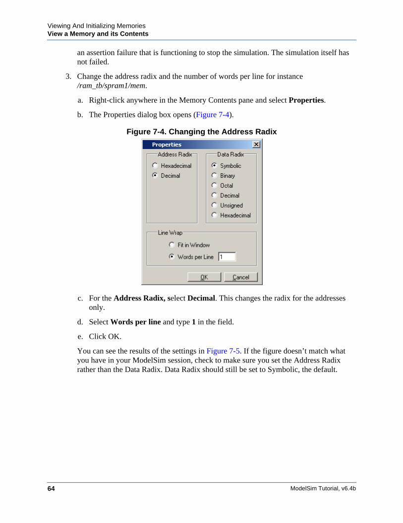
3. Change the address radix and the number of words per line for instance/ram_tb/spram1/mem.
a. Right-click anywhere in the Memory Contents pane and select Properties.
b. The Properties dialog box opens (Figure 7-4).
Figure 7-4. Changing the Address Radix
c. For the Address Radix, select Decimal. This changes the radix for the addressesonly.
d. Select Words per line and type 1 in the field.
e. Click OK.
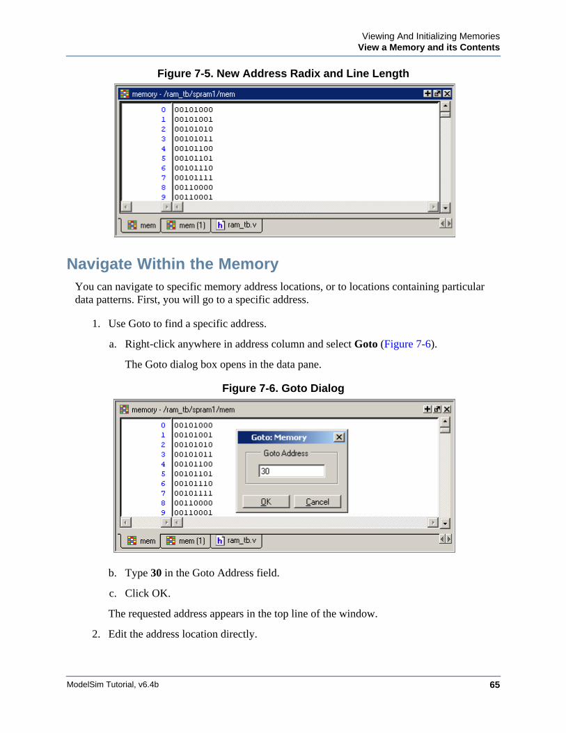
You can see the results of the settings in Figure 7-5. If the figure doesn’t match whatyou have in your ModelSim session, check to make sure you set the Address Radixrather than the Data Radix. Data Radix should still be set to Symbolic, the default.
Viewing And Initializing MemoriesView a Memory and its Contents
ModelSim Tutorial, v6.4b 65
Figure 7-5. New Address Radix and Line Length
Navigate Within the MemoryYou can navigate to specific memory address locations, or to locations containing particulardata patterns. First, you will go to a specific address.
1. Use Goto to find a specific address.
a. Right-click anywhere in address column and select Goto (Figure 7-6).
The Goto dialog box opens in the data pane.
Figure 7-6. Goto Dialog
b. Type 30 in the Goto Address field.
c. Click OK.
The requested address appears in the top line of the window.
2. Edit the address location directly.
ModelSim Tutorial, v6.4b66
Viewing And Initializing MemoriesView a Memory and its Contents
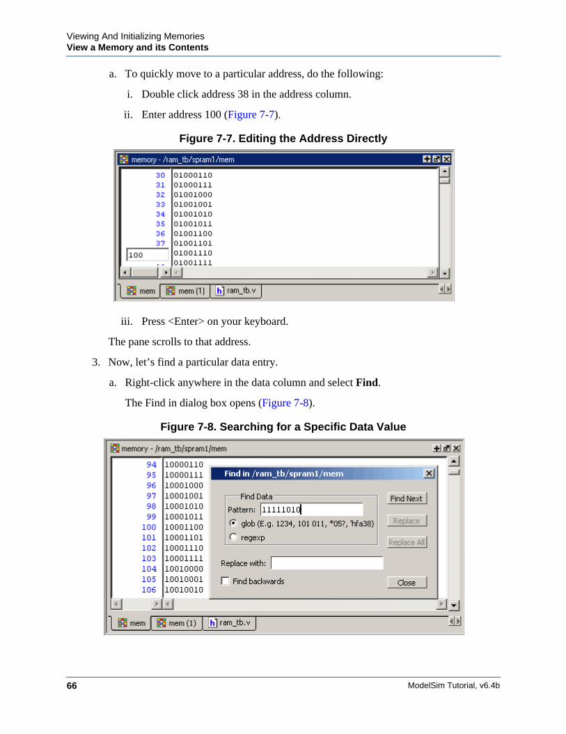
a. To quickly move to a particular address, do the following:
i. Double click address 38 in the address column.
ii. Enter address 100 (Figure 7-7).
Figure 7-7. Editing the Address Directly
iii. Press <Enter> on your keyboard.
The pane scrolls to that address.
3. Now, let’s find a particular data entry.
a. Right-click anywhere in the data column and select Find.
The Find in dialog box opens (Figure 7-8).
Figure 7-8. Searching for a Specific Data Value
Viewing And Initializing MemoriesExport Memory Data to a File
ModelSim Tutorial, v6.4b 67
b. Type 11111010 in the Find data: field and click Find Next.
The data scrolls to the first occurrence of that address. Click Find Next a few moretimes to search through the list.
c. Click Close to close the dialog box.
Export Memory Data to a FileYou can save memory data to a file that can be loaded at some later point in simulation.
1. Export a memory pattern from the /ram_tb/spram1/mem instance to a file.
a. Make sure /ram_tb/spram1/mem is open and selected in the MDI frame.
b. Select File > Export > Memory Data to bring up the Export Memory dialog box(Figure 7-9).
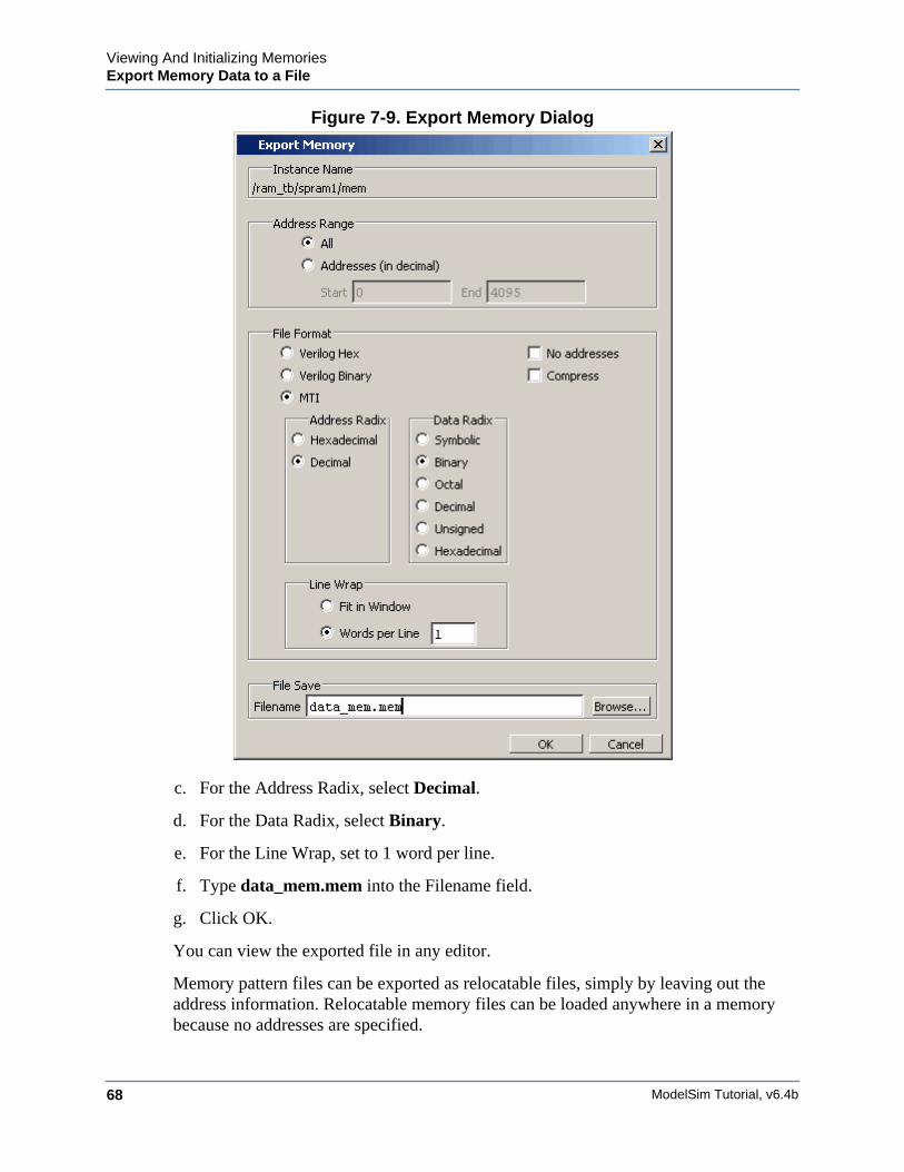
ModelSim Tutorial, v6.4b68
Viewing And Initializing MemoriesExport Memory Data to a File
Figure 7-9. Export Memory Dialog
c. For the Address Radix, select Decimal.
d. For the Data Radix, select Binary.
e. For the Line Wrap, set to 1 word per line.
f. Type data_mem.mem into the Filename field.
g. Click OK.
You can view the exported file in any editor.
Memory pattern files can be exported as relocatable files, simply by leaving out theaddress information. Relocatable memory files can be loaded anywhere in a memorybecause no addresses are specified.
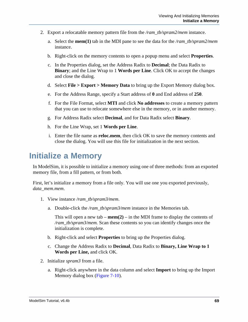
Viewing And Initializing MemoriesInitialize a Memory
ModelSim Tutorial, v6.4b 69
2. Export a relocatable memory pattern file from the /ram_tb/spram2/mem instance.
a. Select the mem(1) tab in the MDI pane to see the data for the /ram_tb/spram2/meminstance.
b. Right-click on the memory contents to open a popup menu and select Properties.
c. In the Properties dialog, set the Address Radix to Decimal; the Data Radix toBinary; and the Line Wrap to 1 Words per Line. Click OK to accept the changesand close the dialog.
d. Select File > Export > Memory Data to bring up the Export Memory dialog box.
e. For the Address Range, specify a Start address of 0 and End address of 250.
f. For the File Format, select MTI and click No addresses to create a memory patternthat you can use to relocate somewhere else in the memory, or in another memory.
g. For Address Radix select Decimal, and for Data Radix select Binary.
h. For the Line Wrap, set 1 Words per Line.
i. Enter the file name as reloc.mem, then click OK to save the memory contents andclose the dialog. You will use this file for initialization in the next section.
Initialize a MemoryIn ModelSim, it is possible to initialize a memory using one of three methods: from an exportedmemory file, from a fill pattern, or from both.
First, let’s initialize a memory from a file only. You will use one you exported previously,data_mem.mem.
1. View instance /ram_tb/spram3/mem.
a. Double-click the /ram_tb/spram3/mem instance in the Memories tab.
This will open a new tab – mem(2) – in the MDI frame to display the contents of/ram_tb/spram3/mem. Scan these contents so you can identify changes once theinitialization is complete.
b. Right-click and select Properties to bring up the Properties dialog.
c. Change the Address Radix to Decimal, Data Radix to Binary, Line Wrap to 1Words per Line, and click OK.
2. Initialize spram3 from a file.
a. Right-click anywhere in the data column and select Import to bring up the ImportMemory dialog box (Figure 7-10).
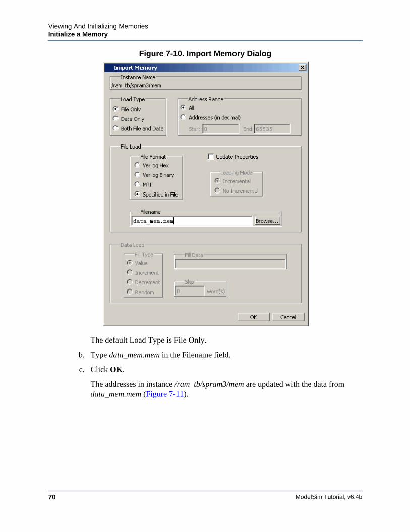
ModelSim Tutorial, v6.4b70
Viewing And Initializing MemoriesInitialize a Memory
Figure 7-10. Import Memory Dialog
The default Load Type is File Only.
b. Type data_mem.mem in the Filename field.
c. Click OK.
The addresses in instance /ram_tb/spram3/mem are updated with the data fromdata_mem.mem (Figure 7-11).
Viewing And Initializing MemoriesInitialize a Memory
ModelSim Tutorial, v6.4b 71
Figure 7-11. Initialized Memory from File and Fill Pattern
In this next step, you will experiment with importing from both a file and a fill pattern.You will initialize spram3 with the 250 addresses of data you exported previously intothe relocatable file reloc.mem. You will also initialize 50 additional address entries witha fill pattern.
3. Import the /ram_tb/spram3/mem instance with a relocatable memory pattern(reloc.mem) and a fill pattern.
a. Right-click in the data column of the mem(2) tab and select Import to bring up theImport Memory dialog box.
b. For Load Type, select Both File and Data.
c. For Address Range, select Addresses and enter 0 as the Start address and 300 as theEnd address.
This means that you will be loading the file from 0 to 300. However, the reloc.memfile contains only 251 addresses of data. Addresses 251 to 300 will be loaded withthe fill data you specify next.
d. For File Load, select the MTI File Format and enter reloc.mem in the Filenamefield.
e. For Data Load, select a Fill Type of Increment.
f. In the Fill Data field, set the seed value of 0 for the incrementing data.
g. Click OK.
h. View the data near address 250 by double-clicking on any address in the Addresscolumn and entering 250.
You can see the specified range of addresses overwritten with the new data. Also, youcan see the incrementing data beginning at address 251 (Figure 7-12).
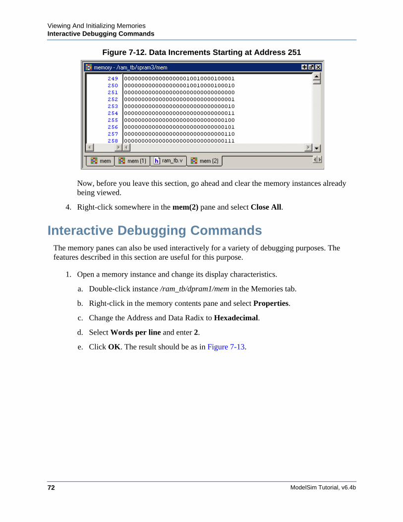
ModelSim Tutorial, v6.4b72
Viewing And Initializing MemoriesInteractive Debugging Commands
Figure 7-12. Data Increments Starting at Address 251
Now, before you leave this section, go ahead and clear the memory instances alreadybeing viewed.
4. Right-click somewhere in the mem(2) pane and select Close All.
Interactive Debugging CommandsThe memory panes can also be used interactively for a variety of debugging purposes. Thefeatures described in this section are useful for this purpose.
1. Open a memory instance and change its display characteristics.
a. Double-click instance /ram_tb/dpram1/mem in the Memories tab.
b. Right-click in the memory contents pane and select Properties.
c. Change the Address and Data Radix to Hexadecimal.
d. Select Words per line and enter 2.
e. Click OK. The result should be as in Figure 7-13.
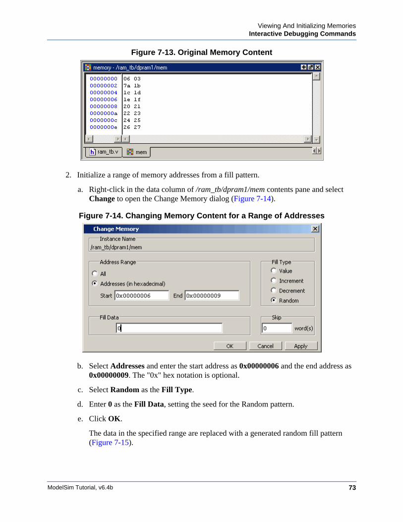
Viewing And Initializing MemoriesInteractive Debugging Commands
ModelSim Tutorial, v6.4b 73
Figure 7-13. Original Memory Content
2. Initialize a range of memory addresses from a fill pattern.
a. Right-click in the data column of /ram_tb/dpram1/mem contents pane and selectChange to open the Change Memory dialog (Figure 7-14).
Figure 7-14. Changing Memory Content for a Range of Addresses
b. Select Addresses and enter the start address as 0x00000006 and the end address as0x00000009. The "0x" hex notation is optional.
c. Select Random as the Fill Type.
d. Enter 0 as the Fill Data, setting the seed for the Random pattern.
e. Click OK.
The data in the specified range are replaced with a generated random fill pattern(Figure 7-15).
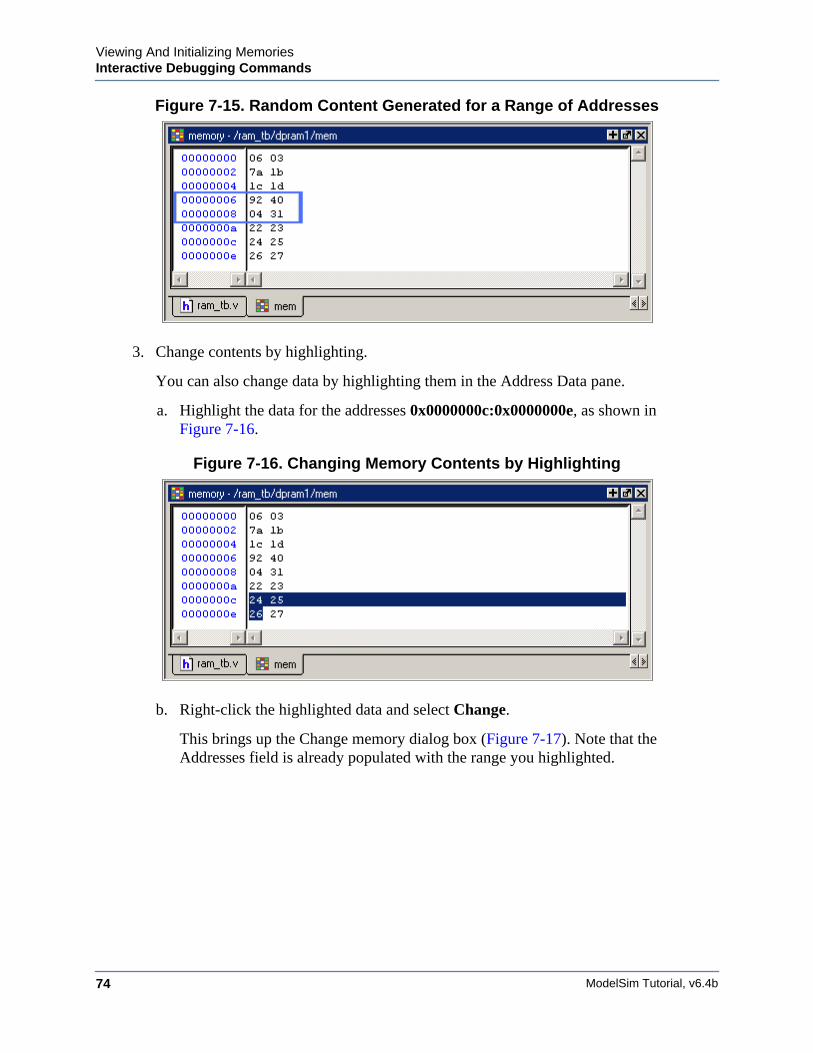
ModelSim Tutorial, v6.4b74
Viewing And Initializing MemoriesInteractive Debugging Commands
Figure 7-15. Random Content Generated for a Range of Addresses
3. Change contents by highlighting.
You can also change data by highlighting them in the Address Data pane.
a. Highlight the data for the addresses 0x0000000c:0x0000000e, as shown inFigure 7-16.
Figure 7-16. Changing Memory Contents by Highlighting
b. Right-click the highlighted data and select Change.
This brings up the Change memory dialog box (Figure 7-17). Note that theAddresses field is already populated with the range you highlighted.
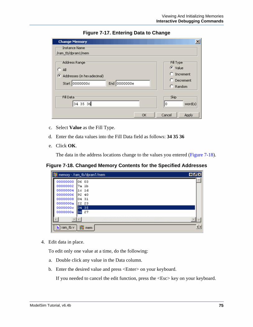
Viewing And Initializing MemoriesInteractive Debugging Commands
ModelSim Tutorial, v6.4b 75
Figure 7-17. Entering Data to Change
c. Select Value as the Fill Type.
d. Enter the data values into the Fill Data field as follows: 34 35 36
e. Click OK.
The data in the address locations change to the values you entered (Figure 7-18).
Figure 7-18. Changed Memory Contents for the Specified Addresses
4. Edit data in place.
To edit only one value at a time, do the following:
a. Double click any value in the Data column.
b. Enter the desired value and press <Enter> on your keyboard.
If you needed to cancel the edit function, press the <Esc> key on your keyboard.

ModelSim Tutorial, v6.4b76
Viewing And Initializing MemoriesInteractive Debugging Commands
Lesson Wrap-Up
This concludes this lesson. Before continuing we need to end the current simulation.
1. Select Simulate > End Simulation. Click Yes.
ModelSim Tutorial, v6.4b 77
Chapter 8Automating Simulation
Introduction
Aside from executing a couple of pre-existing DO files, the previous lessons focused on usingModelSim in interactive mode: executing single commands, one after another, via the GUImenus or Main window command line. In situations where you have repetitive tasks tocomplete, you can increase your productivity with DO files.
DO files are scripts that allow you to execute many commands at once. The scripts can be assimple as a series of ModelSim commands with associated arguments, or they can be full-blownTcl programs with variables, conditional execution, and so forth. You can execute DO filesfrom within the GUI or you can run them from the system command prompt without everinvoking the GUI.
NoteThis lesson assumes that you have added the <install_dir>/modeltech/<platform>directory to your PATH. If you did not, you will need to specify full paths to the tools(i.e., vlib, vmap, vlog, vcom, and vsim) that are used in the lesson.
Related Reading
User’s Manual Chapter: Tcl and Macros (DO Files).
Practical Programming in Tcl and Tk, Brent B. Welch, Copyright 1997
Creating a Simple DO FileCreating DO files is as simple as typing the commands in a text file. Alternatively, you can savethe Main window transcript as a DO file. In this exercise, you will use the commands you enterin the Main window transcript to create a DO file that adds signals to the Wave window,provides stimulus to those signals, and then advances the simulation.
1. Load the test_counter design unit.
a. If necessary, start ModelSim.
b. Change to the directory you created in the "Basic Simulation" lesson.
c. Enter vsim test_counter to load the design unit.
ModelSim Tutorial, v6.4b78
Automating SimulationRunning in Command-Line Mode
2. Enter commands to add signals to the Wave window, force signals, and run thesimulation.
a. Select File > New > Source > Do to create a new DO file.
b. Enter the following commands into the source window:
add wave countadd wave clkadd wave resetforce -freeze clk 0 0, 1 {50 ns} -r 100force reset 1run 100force reset 0run 300force reset 1run 400force reset 0run 200
3. Save the file.
a. Select File > Save As.
b. Type sim.do in the File name: field and save it to the current directory.
4. Load the simulation again and use the DO file.
a. Enter quit -sim at the VSIM> prompt.
b. Enter vsim test_counter at the ModelSim> prompt.
c. Enter do sim.do at the VSIM> prompt.
ModelSim executes the saved commands and draws the waves in the Wave window.
5. When you are done with this exercise, select File > Quit to quit ModelSim.
Running in Command-Line ModeWe use the term "command-line mode" to refer to simulations that are run from a DOS/ UNIXprompt without invoking the GUI. Several ModelSim commands (e.g., vsim, vlib, vlog, etc.)are actually stand-alone executables that can be invoked at the system command prompt.Additionally, you can create a DO file that contains other ModelSim commands and specify thatfile when you invoke the simulator.
1. Create a new directory and copy the tutorial files into it.
Start by creating a new directory for this exercise. Create the directory and copy thefollowing files into it:
• /<install_dir>/examples/tutorials/verilog/automation/counter.v
• /<install_dir>/examples/tutorials/verilog/automation/stim.do
Automating SimulationRunning in Command-Line Mode
ModelSim Tutorial, v6.4b 79
This lesson uses the Verilog file counter.v. If you have a VHDL license, use thecounter.vhd and stim.do files in the /<install_dir>/examples/tutorials/vhdl/automationdirectory instead.
2. Create a new design library and compile the source file.
Again, enter these commands at a DOS/ UNIX prompt in the new directory you createdin step 1.
a. Type vlib work at the DOS/ UNIX prompt.
b. For Verilog, type vlog counter.v at the DOS/ UNIX prompt. For VHDL, type vcomcounter.vhd.
3. Create a DO file.
a. Open a text editor.
b. Type the following lines into a new file:
# list all signals in decimal formatadd list -decimal *
# read in stimulusdo stim.do
# output resultswrite list counter.lst
# quit the simulationquit -f
c. Save the file with the name sim.do and place it in the current directory.
4. Run the batch-mode simulation.
a. Type vsim -c -do sim.do counter -wlf counter.wlf at the DOS/ UNIX prompt.
The -c argument instructs ModelSim not to invoke the GUI. The -wlf argumentsaves the simulation results in a WLF file. This allows you to view the simulationresults in the GUI for debugging purposes.
5. View the list output.
a. Open counter.lst and view the simulation results. Output produced by the Verilogversion of the design should look like the following:
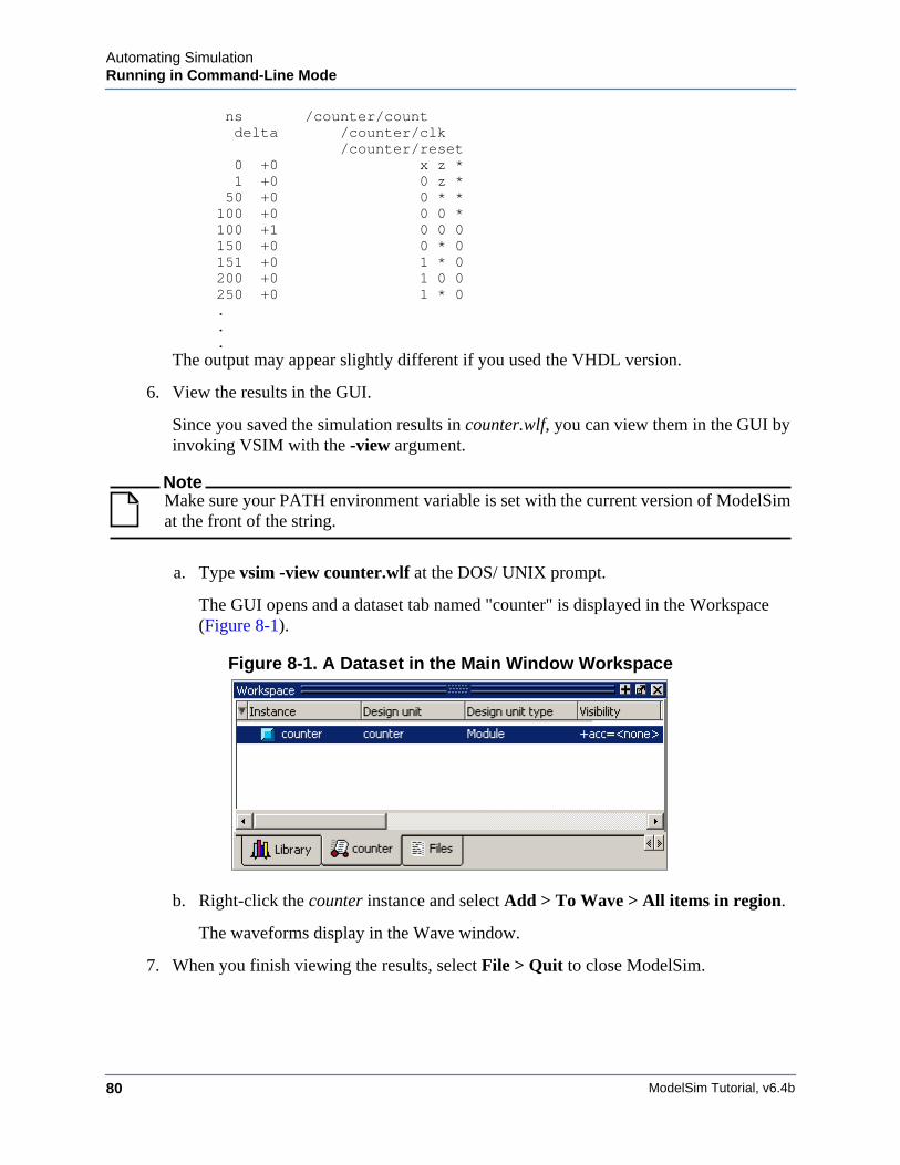
ModelSim Tutorial, v6.4b80
Automating SimulationRunning in Command-Line Mode
ns /counter/count delta /counter/clk /counter/reset 0 +0 x z * 1 +0 0 z * 50 +0 0 * * 100 +0 0 0 * 100 +1 0 0 0 150 +0 0 * 0 151 +0 1 * 0 200 +0 1 0 0 250 +0 1 * 0
.
.
.The output may appear slightly different if you used the VHDL version.
6. View the results in the GUI.
Since you saved the simulation results in counter.wlf, you can view them in the GUI byinvoking VSIM with the -view argument.
NoteMake sure your PATH environment variable is set with the current version of ModelSimat the front of the string.
a. Type vsim -view counter.wlf at the DOS/ UNIX prompt.
The GUI opens and a dataset tab named "counter" is displayed in the Workspace(Figure 8-1).
Figure 8-1. A Dataset in the Main Window Workspace
b. Right-click the counter instance and select Add > To Wave > All items in region.
The waveforms display in the Wave window.
7. When you finish viewing the results, select File > Quit to close ModelSim.
Automating SimulationUsing Tcl with the Simulator
ModelSim Tutorial, v6.4b 81
Using Tcl with the SimulatorThe DO files used in previous exercises contained only ModelSim commands. However, DOfiles are really just Tcl scripts. This means you can include a whole variety of Tcl constructssuch as procedures, conditional operators, math and trig functions, regular expressions, and soforth.
In this exercise, you create a simple Tcl script that tests for certain values on a signal and thenadds bookmarks that zoom the Wave window when that value exists. Bookmarks allow you tosave a particular zoom range and scroll position in the Wave window.
1. Create the script.
a. In a text editor, open a new file and enter the following lines:
proc add_wave_zoom {stime num} {echo "Bookmarking wave $num"bookmark add wave "bk$num" "[expr $stime - 50] [expr $stime +100]" 0}These commands do the following:
• Create a new procedure called "add_wave_zoom" that has two arguments, stimeand num.
• Create a bookmark with a zoom range from the current simulation time minus 50time units to the current simulation time plus 100 time units.
b. Now add these lines to the bottom of the script:
add wave -r /*when {clk'event and clk="1"} { echo "Count is [exa count]" if {[examine count]== "00100111"} { add_wave_zoom $now 1 } elseif {[examine count]== "01000111"} { add_wave_zoom $now 2 }}These commands do the following:
• Add all signals to the Wave window.
• Use a when statement to identify when clk transitions to 1.
• Examine the value of count at those transitions and add a bookmark if it is acertain value.
c. Save the script with the name "add_bkmrk.do."
Save it into the directory you created in Basic Simulation.
2. Load the test_counter design unit.
ModelSim Tutorial, v6.4b82
Automating SimulationUsing Tcl with the Simulator
a. Start ModelSim.
b. Select File > Change Directory and change to the directory you saved the DO fileto in step 1c above.
c. Enter the following command at the QuestaSim> prompt:
vsim -voptargs="+acc" test_counter
3. Execute the DO file and run the design.
a. Type do add_bkmrk.do at the VSIM> prompt.
b. Type run 1500 ns at the VSIM> prompt.
The simulation runs and the DO file creates two bookmarks.
c. If the Wave window is docked in the Main window, click somewhere in the Wavewindow and select Wave > Bookmarks > bk1. If the window is undocked, selectView > Bookmarks > bk1 in the Wave window.
Watch the Wave window zoom on and scroll to the time when count is 00100111.Try the bk2 bookmark as well.
Lesson Wrap-Up
This concludes this lesson.
1. Select File > Quit to close ModelSim.
83
A B F GDC E H I J K L M N O P Q R S T U V XW Y Z
ModelSim Tutorial, v6.4b
— A —add wave command, 55
— B —break icon, 22breakpoints
setting, 22stepping, 25
— C —command-line mode, 78compile order, changing, 34compiling your design, 12, 17cursors, Wave window, 56
— D —design library
working type, 13
— E —error messages, more information, 47external libraries, linking to, 46
— F —folders, in projects, 37
— L —libraries
design library types, 13linking to external libraries, 46mapping to permanently, 51resource libraries, 13working libraries, 13working, creating, 16
linking to external libraries, 46
— M —mapping libraries permanently, 51memories
changing values, 73initializing, 69
memory contents, saving to a file, 67
— O —options, simulation, 39
— P —projects
adding items to, 32creating, 31flow overview, 12organizing with folders, 37simulation configurations, 39
— Q —quit command, 48
— R —radix command, 62run -all, 22run command, 21
— S —saving simulation options, 39simulation
basic flow overview, 11restarting, 23running, 20
simulation configurations, 39stepping after a breakpoint, 25
— T —Tcl, using in the simulator, 81time, measuring in Wave window, 56
— V —vcom command, 62verror command, 47vlib command, 62vlog command, 62vsim command, 16
— W —Wave window
adding items to, 54
Index

84 ModelSim Tutorial, v6.4b
A B F GDC E H I J K L M N O P Q R S T U V XW Y Z
cursors, 56measuring time with cursors, 56zooming, 55
working library, creating, 11, 16
— Z —zooming, Wave window, 55
End-User License AgreementThe latest version of the End-User License Agreement is available on-line at:
www.mentor.com/terms_conditions/enduser.cfm
END-USER LICENSE AGREEMENT (“Agreement”)
This is a legal agreement concerning the use of Software between you, the end user, as an authorizedrepresentative of the company acquiring the license, and Mentor Graphics Corporation and Mentor Graphics(Ireland) Limited acting directly or through their subsidiaries (collectively “Mentor Graphics”). Except for licenseagreements related to the subject matter of this license agreement which are physically signed by you and anauthorized representative of Mentor Graphics, this Agreement and the applicable quotation contain the parties'entire understanding relating to the subject matter and supersede all prior or contemporaneous agreements. If youdo not agree to these terms and conditions, promptly return or, if received electronically, certify destruction ofSoftware and all accompanying items within five days after receipt of Software and receive a full refund of anylicense fee paid.
1. GRANT OF LICENSE. The software programs, including any updates, modifications, revisions, copies, documentationand design data (“Software”), are copyrighted, trade secret and confidential information of Mentor Graphics or itslicensors who maintain exclusive title to all Software and retain all rights not expressly granted by this Agreement.Mentor Graphics grants to you, subject to payment of appropriate license fees, a nontransferable, nonexclusive license touse Software solely: (a) in machine-readable, object-code form; (b) for your internal business purposes; (c) for the licenseterm; and (d) on the computer hardware and at the site authorized by Mentor Graphics. A site is restricted to a one-halfmile (800 meter) radius. Mentor Graphics’ standard policies and programs, which vary depending on Software, licensefees paid or services purchased, apply to the following: (a) relocation of Software; (b) use of Software, which may belimited, for example, to execution of a single session by a single user on the authorized hardware or for a restricted periodof time (such limitations may be technically implemented through the use of authorization codes or similar devices); and(c) support services provided, including eligibility to receive telephone support, updates, modifications, and revisions.
2. EMBEDDED SOFTWARE. If you purchased a license to use embedded software development (“ESD”) Software, ifapplicable, Mentor Graphics grants to you a nontransferable, nonexclusive license to reproduce and distribute executablefiles created using ESD compilers, including the ESD run-time libraries distributed with ESD C and C++ compilerSoftware that are linked into a composite program as an integral part of your compiled computer program, provided thatyou distribute these files only in conjunction with your compiled computer program. Mentor Graphics does NOT grantyou any right to duplicate, incorporate or embed copies of Mentor Graphics' real-time operating systems or otherembedded software products into your products or applications without first signing or otherwise agreeing to a separateagreement with Mentor Graphics for such purpose.
3. BETA CODE. Software may contain code for experimental testing and evaluation (“Beta Code”), which may not be usedwithout Mentor Graphics’ explicit authorization. Upon Mentor Graphics’ authorization, Mentor Graphics grants to you atemporary, nontransferable, nonexclusive license for experimental use to test and evaluate the Beta Code without chargefor a limited period of time specified by Mentor Graphics. This grant and your use of the Beta Code shall not be construedas marketing or offering to sell a license to the Beta Code, which Mentor Graphics may choose not to releasecommercially in any form. If Mentor Graphics authorizes you to use the Beta Code, you agree to evaluate and test theBeta Code under normal conditions as directed by Mentor Graphics. You will contact Mentor Graphics periodicallyduring your use of the Beta Code to discuss any malfunctions or suggested improvements. Upon completion of yourevaluation and testing, you will send to Mentor Graphics a written evaluation of the Beta Code, including its strengths,weaknesses and recommended improvements. You agree that any written evaluations and all inventions, productimprovements, modifications or developments that Mentor Graphics conceived or made during or subsequent to thisAgreement, including those based partly or wholly on your feedback, will be the exclusive property of Mentor Graphics.Mentor Graphics will have exclusive rights, title and interest in all such property. The provisions of this section 3 shallsurvive the termination or expiration of this Agreement.
IMPORTANT INFORMATION
USE OF THIS SOFTWARE IS SUBJECT TO LICENSE RESTRICTIONS. CAREFULLY READ THISLICENSE AGREEMENT BEFORE USING THE SOFTWARE. USE OF SOFTWARE INDICATES YOURCOMPLETE AND UNCONDITIONAL ACCEPTANCE OF THE TERMS AND CONDITIONS SET FORTH
IN THIS AGREEMENT. ANY ADDITIONAL OR DIFFERENT PURCHASE ORDER TERMS ANDCONDITIONS SHALL NOT APPLY.
4. RESTRICTIONS ON USE. You may copy Software only as reasonably necessary to support the authorized use. Eachcopy must include all notices and legends embedded in Software and affixed to its medium and container as received fromMentor Graphics. All copies shall remain the property of Mentor Graphics or its licensors. You shall maintain a record ofthe number and primary location of all copies of Software, including copies merged with other software, and shall makethose records available to Mentor Graphics upon request. You shall not make Software available in any form to anyperson other than employees and on-site contractors, excluding Mentor Graphics' competitors, whose job performancerequires access and who are under obligations of confidentiality. You shall take appropriate action to protect theconfidentiality of Software and ensure that any person permitted access to Software does not disclose it or use it except aspermitted by this Agreement. Except as otherwise permitted for purposes of interoperability as specified by applicableand mandatory local law, you shall not reverse-assemble, reverse-compile, reverse-engineer or in any way derive fromSoftware any source code. You may not sublicense, assign or otherwise transfer Software, this Agreement or the rightsunder it, whether by operation of law or otherwise (“attempted transfer”), without Mentor Graphics’ prior written consentand payment of Mentor Graphics’ then-current applicable transfer charges. Any attempted transfer without MentorGraphics' prior written consent shall be a material breach of this Agreement and may, at Mentor Graphics' option, result inthe immediate termination of the Agreement and licenses granted under this Agreement. The terms of this Agreement,including without limitation, the licensing and assignment provisions shall be binding upon your successors in interestand assigns. The provisions of this section 4 shall survive the termination or expiration of this Agreement.
5. LIMITED WARRANTY.
5.1. Mentor Graphics warrants that during the warranty period Software, when properly installed, will substantiallyconform to the functional specifications set forth in the applicable user manual. Mentor Graphics does not warrantthat Software will meet your requirements or that operation of Software will be uninterrupted or error free. Thewarranty period is 90 days starting on the 15th day after delivery or upon installation, whichever first occurs. Youmust notify Mentor Graphics in writing of any nonconformity within the warranty period. This warranty shall not bevalid if Software has been subject to misuse, unauthorized modification or improper installation. MENTORGRAPHICS' ENTIRE LIABILITY AND YOUR EXCLUSIVE REMEDY SHALL BE, AT MENTOR GRAPHICS'OPTION, EITHER (A) REFUND OF THE PRICE PAID UPON RETURN OF SOFTWARE TO MENTORGRAPHICS OR (B) MODIFICATION OR REPLACEMENT OF SOFTWARE THAT DOES NOT MEET THISLIMITED WARRANTY, PROVIDED YOU HAVE OTHERWISE COMPLIED WITH THIS AGREEMENT.MENTOR GRAPHICS MAKES NO WARRANTIES WITH RESPECT TO: (A) SERVICES; (B) SOFTWAREWHICH IS LICENSED TO YOU FOR A LIMITED TERM OR LICENSED AT NO COST; OR(C) EXPERIMENTAL BETA CODE; ALL OF WHICH ARE PROVIDED “AS IS.”
5.2. THE WARRANTIES SET FORTH IN THIS SECTION 5 ARE EXCLUSIVE. NEITHER MENTOR GRAPHICSNOR ITS LICENSORS MAKE ANY OTHER WARRANTIES, EXPRESS, IMPLIED OR STATUTORY, WITHRESPECT TO SOFTWARE OR OTHER MATERIAL PROVIDED UNDER THIS AGREEMENT. MENTORGRAPHICS AND ITS LICENSORS SPECIFICALLY DISCLAIM ALL IMPLIED WARRANTIES OFMERCHANTABILITY AND FITNESS FOR A PARTICULAR PURPOSE AND NON-INFRINGEMENT OFINTELLECTUAL PROPERTY.
6. LIMITATION OF LIABILITY. EXCEPT WHERE THIS EXCLUSION OR RESTRICTION OF LIABILITYWOULD BE VOID OR INEFFECTIVE UNDER APPLICABLE LAW, IN NO EVENT SHALL MENTOR GRAPHICSOR ITS LICENSORS BE LIABLE FOR INDIRECT, SPECIAL, INCIDENTAL, OR CONSEQUENTIAL DAMAGES(INCLUDING LOST PROFITS OR SAVINGS) WHETHER BASED ON CONTRACT, TORT OR ANY OTHERLEGAL THEORY, EVEN IF MENTOR GRAPHICS OR ITS LICENSORS HAVE BEEN ADVISED OF THEPOSSIBILITY OF SUCH DAMAGES. IN NO EVENT SHALL MENTOR GRAPHICS' OR ITS LICENSORS'LIABILITY UNDER THIS AGREEMENT EXCEED THE AMOUNT PAID BY YOU FOR THE SOFTWARE ORSERVICE GIVING RISE TO THE CLAIM. IN THE CASE WHERE NO AMOUNT WAS PAID, MENTORGRAPHICS AND ITS LICENSORS SHALL HAVE NO LIABILITY FOR ANY DAMAGES WHATSOEVER. THEPROVISIONS OF THIS SECTION 6 SHALL SURVIVE THE EXPIRATION OR TERMINATION OF THISAGREEMENT.
7. LIFE ENDANGERING ACTIVITIES. NEITHER MENTOR GRAPHICS NOR ITS LICENSORS SHALL BELIABLE FOR ANY DAMAGES RESULTING FROM OR IN CONNECTION WITH THE USE OF SOFTWARE INANY APPLICATION WHERE THE FAILURE OR INACCURACY OF THE SOFTWARE MIGHT RESULT INDEATH OR PERSONAL INJURY. THE PROVISIONS OF THIS SECTION 7 SHALL SURVIVE THEEXPIRATION OR TERMINATION OF THIS AGREEMENT.
8. INDEMNIFICATION. YOU AGREE TO INDEMNIFY AND HOLD HARMLESS MENTOR GRAPHICS AND ITSLICENSORS FROM ANY CLAIMS, LOSS, COST, DAMAGE, EXPENSE, OR LIABILITY, INCLUDINGATTORNEYS' FEES, ARISING OUT OF OR IN CONNECTION WITH YOUR USE OF SOFTWARE AS

DESCRIBED IN SECTION 7. THE PROVISIONS OF THIS SECTION 8 SHALL SURVIVE THE EXPIRATION ORTERMINATION OF THIS AGREEMENT.
9. INFRINGEMENT.
9.1. Mentor Graphics will defend or settle, at its option and expense, any action brought against you alleging thatSoftware infringes a patent or copyright or misappropriates a trade secret in the United States, Canada, Japan, ormember state of the European Patent Office. Mentor Graphics will pay any costs and damages finally awardedagainst you that are attributable to the infringement action. You understand and agree that as conditions to MentorGraphics' obligations under this section you must: (a) notify Mentor Graphics promptly in writing of the action;(b) provide Mentor Graphics all reasonable information and assistance to defend or settle the action; and (c) grantMentor Graphics sole authority and control of the defense or settlement of the action.
9.2. If an infringement claim is made, Mentor Graphics may, at its option and expense: (a) replace or modify Software sothat it becomes noninfringing; (b) procure for you the right to continue using Software; or (c) require the return ofSoftware and refund to you any license fee paid, less a reasonable allowance for use.
9.3. Mentor Graphics has no liability to you if infringement is based upon: (a) the combination of Software with anyproduct not furnished by Mentor Graphics; (b) the modification of Software other than by Mentor Graphics; (c) theuse of other than a current unaltered release of Software; (d) the use of Software as part of an infringing process; (e) aproduct that you make, use or sell; (f) any Beta Code contained in Software; (g) any Software provided by MentorGraphics’ licensors who do not provide such indemnification to Mentor Graphics’ customers; or (h) infringement byyou that is deemed willful. In the case of (h) you shall reimburse Mentor Graphics for its attorney fees and other costsrelated to the action upon a final judgment.
9.4. THIS SECTION IS SUBJECT TO SECTION 6 ABOVE AND STATES THE ENTIRE LIABILITY OF MENTORGRAPHICS AND ITS LICENSORS AND YOUR SOLE AND EXCLUSIVE REMEDY WITH RESPECT TOANY ALLEGED PATENT OR COPYRIGHT INFRINGEMENT OR TRADE SECRET MISAPPROPRIATIONBY ANY SOFTWARE LICENSED UNDER THIS AGREEMENT.
10. TERM. This Agreement remains effective until expiration or termination. This Agreement will immediately terminateupon notice if you exceed the scope of license granted or otherwise fail to comply with the provisions of Sections 1, 2, or4. For any other material breach under this Agreement, Mentor Graphics may terminate this Agreement upon 30 dayswritten notice if you are in material breach and fail to cure such breach within the 30 day notice period. If Software wasprovided for limited term use, this Agreement will automatically expire at the end of the authorized term. Upon anytermination or expiration, you agree to cease all use of Software and return it to Mentor Graphics or certify deletion anddestruction of Software, including all copies, to Mentor Graphics’ reasonable satisfaction.
11. EXPORT. Software is subject to regulation by local laws and United States government agencies, which prohibit exportor diversion of certain products, information about the products, and direct products of the products to certain countriesand certain persons. You agree that you will not export any Software or direct product of Software in any manner withoutfirst obtaining all necessary approval from appropriate local and United States government agencies.
12. RESTRICTED RIGHTS NOTICE. Software was developed entirely at private expense and is commercial computersoftware provided with RESTRICTED RIGHTS. Use, duplication or disclosure by the U.S. Government or a U.S.Government subcontractor is subject to the restrictions set forth in the license agreement under which Software wasobtained pursuant to DFARS 227.7202-3(a) or as set forth in subparagraphs (c)(1) and (2) of the Commercial ComputerSoftware - Restricted Rights clause at FAR 52.227-19, as applicable. Contractor/manufacturer is Mentor GraphicsCorporation, 8005 SW Boeckman Road, Wilsonville, Oregon 97070-7777 USA.
13. THIRD PARTY BENEFICIARY. For any Software under this Agreement licensed by Mentor Graphics from Microsoftor other licensors, Microsoft or the applicable licensor is a third party beneficiary of this Agreement with the right toenforce the obligations set forth herein.
14. AUDIT RIGHTS. You will monitor access to, location and use of Software. With reasonable prior notice and duringyour normal business hours, Mentor Graphics shall have the right to review your software monitoring system andreasonably relevant records to confirm your compliance with the terms of this Agreement, an addendum to thisAgreement or U.S. or other local export laws. Such review may include FLEXlm or FLEXnet report log files that youshall capture and provide at Mentor Graphics’ request. Mentor Graphics shall treat as confidential information all of yourinformation gained as a result of any request or review and shall only use or disclose such information as required by lawor to enforce its rights under this Agreement or addendum to this Agreement. The provisions of this section 14 shallsurvive the expiration or termination of this Agreement.

15. CONTROLLING LAW, JURISDICTION AND DISPUTE RESOLUTION. THIS AGREEMENT SHALL BEGOVERNED BY AND CONSTRUED UNDER THE LAWS OF THE STATE OF OREGON, USA, IF YOU ARELOCATED IN NORTH OR SOUTH AMERICA, AND THE LAWS OF IRELAND IF YOU ARE LOCATEDOUTSIDE OF NORTH OR SOUTH AMERICA. All disputes arising out of or in relation to this Agreement shall besubmitted to the exclusive jurisdiction of Portland, Oregon when the laws of Oregon apply, or Dublin, Ireland when thelaws of Ireland apply. Notwithstanding the foregoing, all disputes in Asia (except for Japan) arising out of or in relation tothis Agreement shall be resolved by arbitration in Singapore before a single arbitrator to be appointed by the Chairman ofthe Singapore International Arbitration Centre (“SIAC”) to be conducted in the English language, in accordance with theArbitration Rules of the SIAC in effect at the time of the dispute, which rules are deemed to be incorporated by referencein this section 15. This section shall not restrict Mentor Graphics’ right to bring an action against you in the jurisdictionwhere your place of business is located. The United Nations Convention on Contracts for the International Sale of Goodsdoes not apply to this Agreement.
16. SEVERABILITY. If any provision of this Agreement is held by a court of competent jurisdiction to be void, invalid,unenforceable or illegal, such provision shall be severed from this Agreement and the remaining provisions will remain infull force and effect.
17. PAYMENT TERMS AND MISCELLANEOUS. You will pay amounts invoiced, in the currency specified on theapplicable invoice, within 30 days from the date of such invoice. Any past due invoices will be subject to the impositionof interest charges in the amount of one and one-half percent per month or the applicable legal rate currently in effect,whichever is lower. Some Software may contain code distributed under a third party license agreement that may provideadditional rights to you. Please see the applicable Software documentation for details. This Agreement may only bemodified in writing by authorized representatives of the parties. Waiver of terms or excuse of breach must be in writingand shall not constitute subsequent consent, waiver or excuse.
Rev. 060210, Part No. 227900