Embed Size (px)
Citation preview
Models: 8600, 8601, 8602, 8610, 8612, 8614, 8616
Programmable DC Electronic Loads
PROGRAMMING MANUAL

Safety Summary
The following general safety precautions must be observed during all phases of operation of this instrument. Failure to comply with these precautions or with specific warnings elsewhere in this manual violates safety standards of design, manufacture, and intended use of the instrument. We assume no liability for the customer’s failure to comply with these requirements. ENVIRONMENTAL CONDITIONS This instrument is intended for indoor use, pollution degree 2 environments. It is designed to operate at a maximum relative humidity of 95% and at altitudes of up to 2000 meters. Refer to the specifications tables for the AC mains voltage requirements and ambient operating temperature range. BEFORE APPLYING POWER Verify that all safety precautions are taken. Note the instrument's external markings described under "Safety Symbols". GROUND THE INSTRUMENT This product is a Safety Class 1 instrument (provided with a protective earth terminal). To minimize shock hazard, the instrument chassis and cover must be connected to an electrical ground. The instrument must be connected to the AC mains power through a grounded power cable, with the ground wire firmly connected to an electrical ground (safety ground) at the power outlet. Note: Any interruption of the protective (grounding) conductor or disconnection of the protective earth terminal will cause a potential shock hazard that could result in personal injury. DO NOT OPERATE IN AN EXPLOSIVE ATMOSPHERE Do not operate the instrument in the presence of fumes or flammable gases. KEEP AWAY FROM LIVE CIRCUITS Operating personnel must not remove instrument covers except as instructed in this guide for installing or removing electronic load modules. Component replacement and internal adjustments must be made only by qualified service personnel. Do not replace components with power cable connected. Under certain conditions dangerous voltages may exist even with the power cable removed. To avoid injuries, always disconnect power, discharge circuits, and remove external voltage sources before touching components. DO NOT SERVICE OR ADJUST ALONE Do not try to do some internal service or adjustment unless another person capable of rendering first aid resuscitation is present.
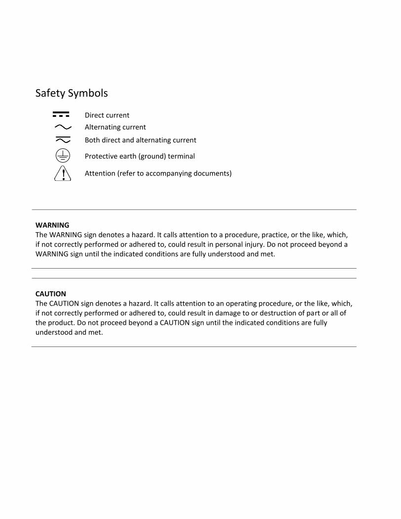
Safety Symbols
Direct current
Alternating current
Both direct and alternating current
Protective earth (ground) terminal
Attention (refer to accompanying documents)
WARNING The WARNING sign denotes a hazard. It calls attention to a procedure, practice, or the like, which, if not correctly performed or adhered to, could result in personal injury. Do not proceed beyond a WARNING sign until the indicated conditions are fully understood and met.
CAUTION The CAUTION sign denotes a hazard. It calls attention to an operating procedure, or the like, which, if not correctly performed or adhered to, could result in damage to or destruction of part or all of the product. Do not proceed beyond a CAUTION sign until the indicated conditions are fully understood and met.
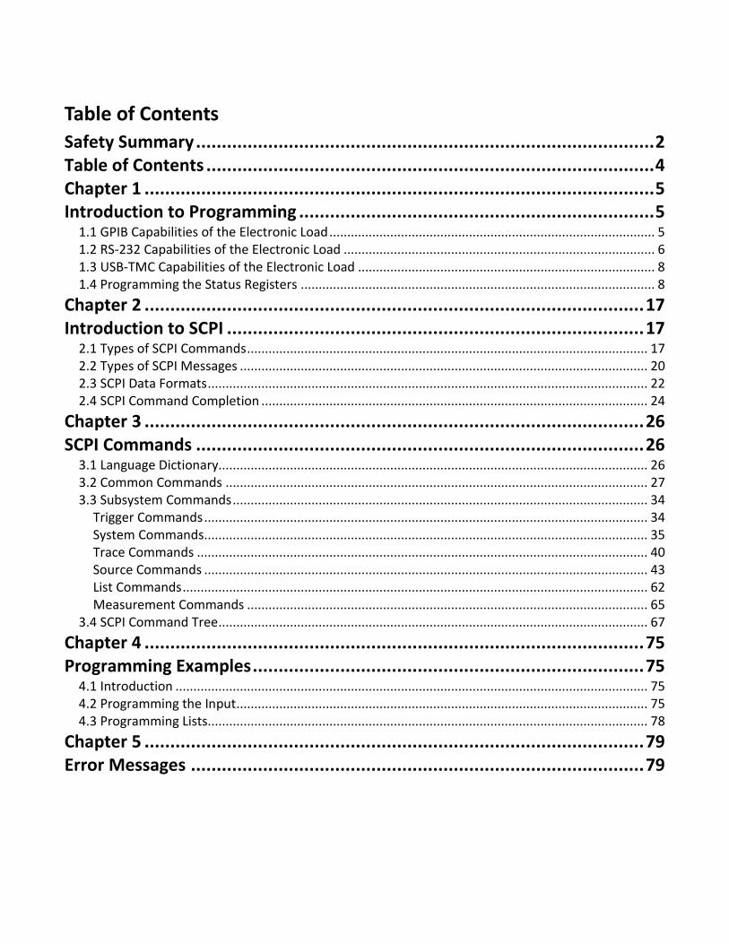
Table of Contents
Safety Summary ......................................................................................... 2
Table of Contents ....................................................................................... 4
Chapter 1 ................................................................................................... 5
Introduction to Programming ..................................................................... 5
1.1 GPIB Capabilities of the Electronic Load ........................................................................................... 5
1.2 RS-232 Capabilities of the Electronic Load ....................................................................................... 6
1.3 USB-TMC Capabilities of the Electronic Load ................................................................................... 8
1.4 Programming the Status Registers ................................................................................................... 8
Chapter 2 ................................................................................................. 17
Introduction to SCPI ................................................................................. 17
2.1 Types of SCPI Commands ................................................................................................................ 17
2.2 Types of SCPI Messages .................................................................................................................. 20
2.3 SCPI Data Formats ........................................................................................................................... 22
2.4 SCPI Command Completion ............................................................................................................ 24
Chapter 3 ................................................................................................. 26
SCPI Commands ....................................................................................... 26
3.1 Language Dictionary........................................................................................................................ 26
3.2 Common Commands ...................................................................................................................... 27
3.3 Subsystem Commands .................................................................................................................... 34
Trigger Commands ............................................................................................................................ 34
System Commands ............................................................................................................................ 35
Trace Commands .............................................................................................................................. 40
Source Commands ............................................................................................................................ 43
List Commands .................................................................................................................................. 62
Measurement Commands ................................................................................................................ 65
3.4 SCPI Command Tree ........................................................................................................................ 67
Chapter 4 ................................................................................................. 75
Programming Examples ............................................................................ 75
4.1 Introduction .................................................................................................................................... 75
4.2 Programming the Input ................................................................................................................... 75
4.3 Programming Lists........................................................................................................................... 78
Chapter 5 ................................................................................................. 79
Error Messages ........................................................................................ 79
5
Chapter 1
Introduction to Programming
This guide contains programming information for the B&K Precision 8600 series DC electronic load. Unless otherwise noted, this document will refer to all of these instruments as “electronic load”.
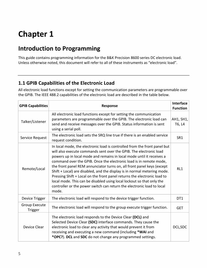
1.1 GPIB Capabilities of the Electronic Load All electronic load functions except for setting the communication parameters are programmable over the GPIB. The IEEE 488.2 capabilities of the electronic load are described in the table below.
GPIB Capabilities Response Interface Function
Talker/Listener
All electronic load functions except for setting the communication parameters are programmable over the GPIB. The electronic load can send and receive messages over the GPIB. Status information is sent using a serial poll.
AH1, SH1, T6, L4
Service Request The electronic load sets the SRQ line true if there is an enabled service request condition.
SR1
Remote/Local
In local mode, the electronic load is controlled from the front panel but will also execute commands sent over the GPIB. The electronic load powers up in local mode and remains in local mode until it receives a command over the GPIB. Once the electronic load is in remote mode, the front panel REM annunciator turns on, all front panel keys (except Shift + Local) are disabled, and the display is in normal metering mode. Pressing Shift + Local on the front panel returns the electronic load to local mode. This can be disabled using local lockout so that only the controller or the power switch can return the electronic load to local mode.
RL1
Device Trigger The electronic load will respond to the device trigger function. DT1
Group Execute Trigger
The electronic load will respond to the group execute trigger function. GET
Device Clear
The electronic load responds to the Device Clear (DCL) and Selected Device Clear (SDC) interface commands. They cause the electronic load to clear any activity that would prevent it from receiving and executing a new command (including *WAI and *OPC?). DCL and SDC do not change any programmed settings.
DCL,SDC
6
GPIB Address The electronic load operates from a GPIB address that is set from the front panel. To set the GPIB address, press Shift + ⑦ (System menu) on the front panel and enter the address using the Entry keys. The address can be set from 0 to 30. The GPIB address is stored in non-volatile memory.
1.2 RS-232 Capabilities of the Electronic Load Use a cable with two serial interfaces (DB9) to connect the electronic load and PC. It can be activated by selecting <RS-232> in <Communication> of the System menu (Shift + 8 on the front panel). NOTE: There are two serial interfaces on the rear panel: the top 9-pin COM (female) interface is the RS-232 communication interface and the bottom 9-pin COM (male) serial port connection is not for use. All SCPI commands are available through RS-232 programming. The EIA RS-232 standard defines the interconnections between data terminal equipment (DTE) and data communications equipment (DCE). The electronic load is designed to be a DTE and can be connected to another DTE such as a PC COM port through a null modem cable.
NOTE: The RS-232 settings in your program must match the settings specified in the front panel System menu. Press Shift + 8 on the front panel to enter the System menu if you need to change the settings. You can break data transmissions by sending a ^C or ^X character string to the electronic load. This clears any pending operation and discards any pending output.
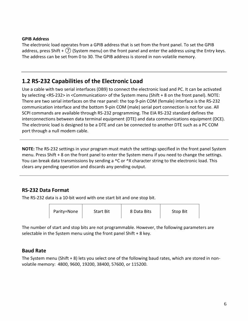
RS-232 Data Format
The RS-232 data is a 10-bit word with one start bit and one stop bit. The number of start and stop bits are not programmable. However, the following parameters are selectable in the System menu using the front panel Shift + 8 key.
Baud Rate
The System menu (Shift + 8) lets you select one of the following baud rates, which are stored in non-volatile memory: 4800, 9600, 19200, 38400, 57600, or 115200.
Parity=None Start Bit 8 Data Bits Stop Bit
7
Parity
None - eight data bits without parity Even - seven data bits with even parity Odd - seven data bits with odd parity
RS-232 Flow Control
The RS-232 interface supports the following flow control options. For each case, the electronic load will send a maximum of five characters after hold-off is asserted by the controller. The electronic load is capable of receiving as many as fifteen additional characters after it asserts hold-off.
The electronic load asserts its Request to Send (RTS) line to signal hold-off when its input buffer
is almost full, and it interprets its Clear to Send (CTS) line as a hold-off signal from the
controller.
When the input queue of the electronic load becomes more than ¾ full, the instrument issues
an X-OFF command. The control program should respond to this and stop sending characters
until the electronic load issues the X-ON, which it will do once its input buffer has dropped
below half-full. The electronic load recognizes X_ON and X_OFF sent from the controller. An X-
OFF will cause the electronic load to stop outputting characters until it sees an X-ON.
NONE: There is no flow control.
Flow control options are stored in non-volatile memory.
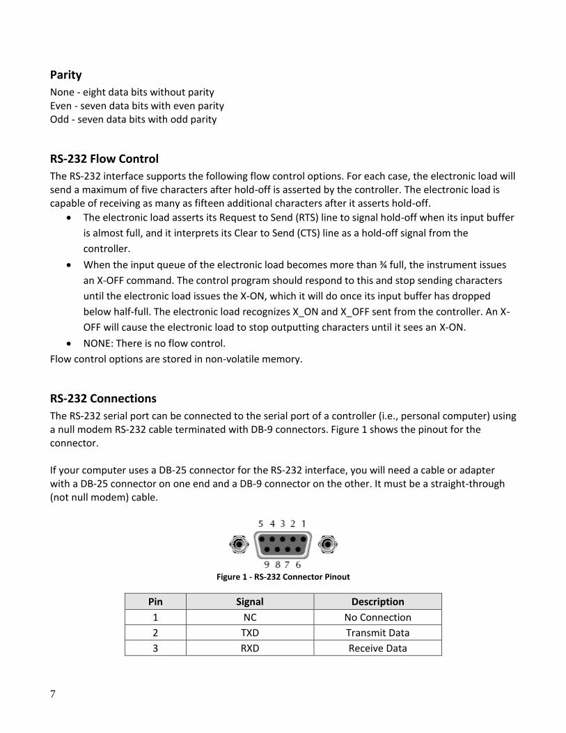
RS-232 Connections
The RS-232 serial port can be connected to the serial port of a controller (i.e., personal computer) using a null modem RS-232 cable terminated with DB-9 connectors. Figure 1 shows the pinout for the connector. If your computer uses a DB-25 connector for the RS-232 interface, you will need a cable or adapter with a DB-25 connector on one end and a DB-9 connector on the other. It must be a straight-through (not null modem) cable.
Figure 1 - RS-232 Connector Pinout
Pin Signal Description
1 NC No Connection
2 TXD Transmit Data
3 RXD Receive Data
8
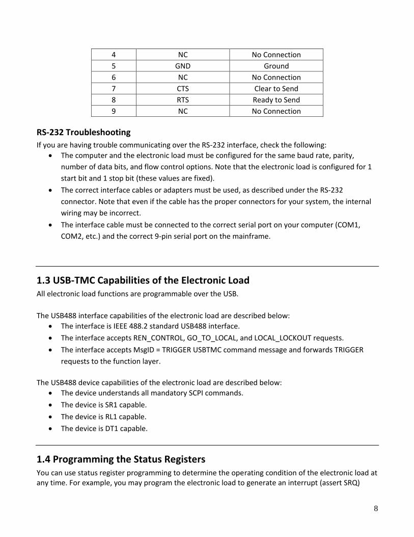
4 NC No Connection
5 GND Ground
6 NC No Connection
7 CTS Clear to Send
8 RTS Ready to Send
9 NC No Connection
RS-232 Troubleshooting
If you are having trouble communicating over the RS-232 interface, check the following:
The computer and the electronic load must be configured for the same baud rate, parity,
number of data bits, and flow control options. Note that the electronic load is configured for 1
start bit and 1 stop bit (these values are fixed).
The correct interface cables or adapters must be used, as described under the RS-232
connector. Note that even if the cable has the proper connectors for your system, the internal
wiring may be incorrect.
The interface cable must be connected to the correct serial port on your computer (COM1,
COM2, etc.) and the correct 9-pin serial port on the mainframe.
1.3 USB-TMC Capabilities of the Electronic Load All electronic load functions are programmable over the USB.
The USB488 interface capabilities of the electronic load are described below:
The interface is IEEE 488.2 standard USB488 interface.
The interface accepts REN_CONTROL, GO_TO_LOCAL, and LOCAL_LOCKOUT requests.
The interface accepts MsgID = TRIGGER USBTMC command message and forwards TRIGGER
requests to the function layer.
The USB488 device capabilities of the electronic load are described below:
The device understands all mandatory SCPI commands.
The device is SR1 capable.
The device is RL1 capable.
The device is DT1 capable.
1.4 Programming the Status Registers You can use status register programming to determine the operating condition of the electronic load at any time. For example, you may program the electronic load to generate an interrupt (assert SRQ)
9
when an event such as a current protection occurs. When the interrupt occurs, your program can then act on the event in the appropriate fashion.
The following table defines the status bits. Figure shows the status register structure of the electronic load. The Standard Event, Status Byte, and Service Request Enable registers and the Output Queue perform standard GPIB functions as defined in the IEEE 488.2 Standard Digital Interface for Programmable Instrumentation. The Operation Status and Questionable Status registers implement functions that are specific to the electronic load.
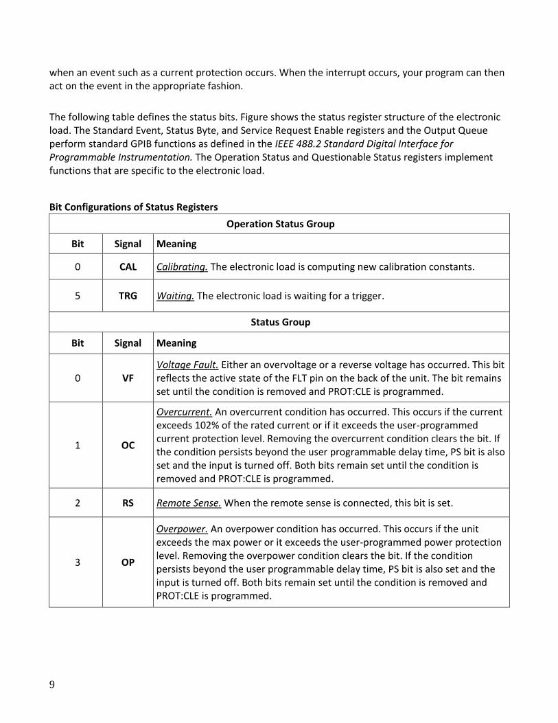
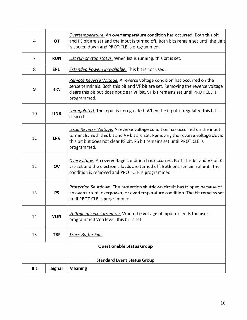
Bit Configurations of Status Registers
Operation Status Group
Bit Signal Meaning
0 CAL Calibrating. The electronic load is computing new calibration constants.
5 TRG Waiting. The electronic load is waiting for a trigger.
Status Group
Bit Signal Meaning
0 VF Voltage Fault. Either an overvoltage or a reverse voltage has occurred. This bit reflects the active state of the FLT pin on the back of the unit. The bit remains set until the condition is removed and PROT:CLE is programmed.
1 OC
Overcurrent. An overcurrent condition has occurred. This occurs if the current exceeds 102% of the rated current or if it exceeds the user-programmed current protection level. Removing the overcurrent condition clears the bit. If the condition persists beyond the user programmable delay time, PS bit is also set and the input is turned off. Both bits remain set until the condition is removed and PROT:CLE is programmed.
2 RS Remote Sense. When the remote sense is connected, this bit is set.
3 OP
Overpower. An overpower condition has occurred. This occurs if the unit exceeds the max power or it exceeds the user-programmed power protection level. Removing the overpower condition clears the bit. If the condition persists beyond the user programmable delay time, PS bit is also set and the input is turned off. Both bits remain set until the condition is removed and PROT:CLE is programmed.
10
4 OT Overtemperature. An overtemperature condition has occurred. Both this bit and PS bit are set and the input is turned off. Both bits remain set until the unit is cooled down and PROT:CLE is programmed.
7 RUN List run or stop status. When list is running, this bit is set.
8 EPU Extended Power Unavailable. This bit is not used.
9 RRV
Remote Reverse Voltage. A reverse voltage condition has occurred on the sense terminals. Both this bit and VF bit are set. Removing the reverse voltage clears this bit but does not clear VF bit. VF bit remains set until PROT:CLE is programmed.
10 UNR Unregulated. The input is unregulated. When the input is regulated this bit is cleared.
11 LRV
Local Reverse Voltage. A reverse voltage condition has occurred on the input terminals. Both this bit and VF bit are set. Removing the reverse voltage clears this bit but does not clear PS bit. PS bit remains set until PROT:CLE is programmed.
12 OV Overvoltage. An overvoltage condition has occurred. Both this bit and VF bit 0 are set and the electronic loads are turned off. Both bits remain set until the condition is removed and PROT:CLE is programmed.
13 PS Protection Shutdown. The protection shutdown circuit has tripped because of an overcurrent, overpower, or overtemperature condition. The bit remains set until PROT:CLE is programmed.
14 VON Voltage of sink current on. When the voltage of input exceeds the user-programmed Von level, this bit is set.
15 TBF Trace Buffer Full.
Questionable Status Group
Standard Event Status Group
Bit Signal Meaning
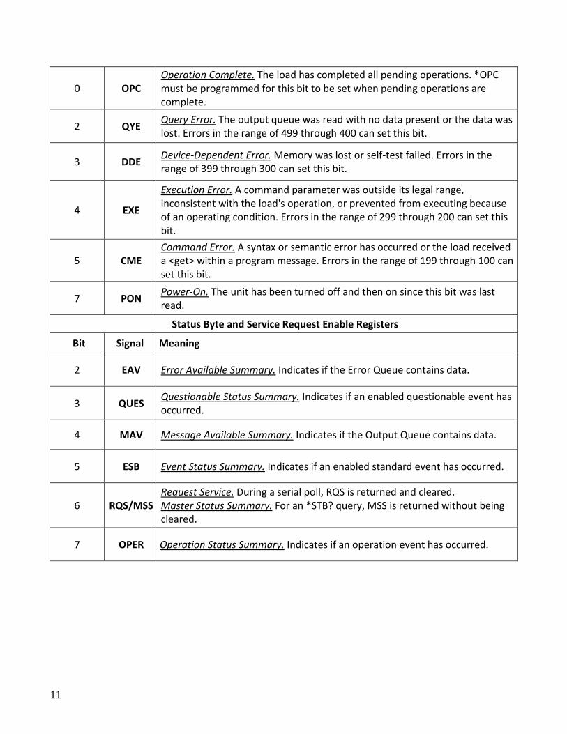
11
0 OPC Operation Complete. The load has completed all pending operations. *OPC must be programmed for this bit to be set when pending operations are complete.
2 QYE Query Error. The output queue was read with no data present or the data was lost. Errors in the range of 499 through 400 can set this bit.
3 DDE Device-Dependent Error. Memory was lost or self-test failed. Errors in the range of 399 through 300 can set this bit.
4 EXE
Execution Error. A command parameter was outside its legal range, inconsistent with the load's operation, or prevented from executing because of an operating condition. Errors in the range of 299 through 200 can set this bit.
5 CME Command Error. A syntax or semantic error has occurred or the load received a <get> within a program message. Errors in the range of 199 through 100 can set this bit.
7 PON Power-On. The unit has been turned off and then on since this bit was last read.
Status Byte and Service Request Enable Registers
Bit Signal Meaning
2 EAV Error Available Summary. Indicates if the Error Queue contains data.
3 QUES Questionable Status Summary. Indicates if an enabled questionable event has occurred.
4 MAV Message Available Summary. Indicates if the Output Queue contains data.
5 ESB Event Status Summary. Indicates if an enabled standard event has occurred.
6 RQS/MSS Request Service. During a serial poll, RQS is returned and cleared. Master Status Summary. For an *STB? query, MSS is returned without being cleared.
7 OPER Operation Status Summary. Indicates if an operation event has occurred.
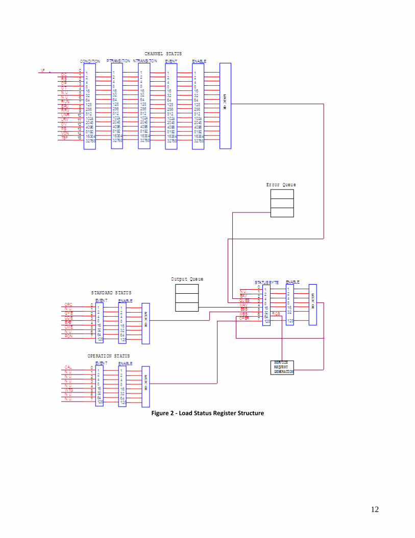
12
Figure 2 - Load Status Register Structure
13
Condition registers All status register sets have a condition register. A condition register is a real-time, read-only register that constantly updates to reflect the current operating conditions of the instrument. Use the :CONDition? query commands in the STATus Subsystem to read the condition registers. See Chapter 3 for more information.
Event registers Each status register set has an event register. An event register is a latched, read-only register whose bits are set by the corresponding condition register. Once a bit in an event register is set, it remains set (latched) until the register is cleared by a specific clearing operation. The bits of an event register are logically ANDed with the bits of the corresponding enable register and applied to an OR gate. The output of the OR gate is applied to the Status Byte Register. Use the *ESR? Common Command to read the Standard Event Register. All other event registers are read using the :EVENt? query commands in the STATus Subsystem. See Chapter 3 for more information. An event register is cleared when it is read. The following operations clear all event registers:
Cycling power
Sending *CLS
Enable registers Each status register set has an enable register. An enable register is programmed by you and serves as a mask for the corresponding event register. An event bit is masked when the corresponding bit in the enable register is cleared (0). When masked, a set bit in an event register cannot set a bit in the Status Byte Register (1 AND 0 = 0). To use the Status Byte Register to detect events (i.e., serial poll), you must unmask the events by setting (1) the appropriate bits of the enable registers. To program and query the Standard Event Status Register, use the *ESE and *ESE? Common Commands respectively. All other enable registers are programmed and queried using the :ENABle and :ENABLe? commands in the STATus Subsystem. See Chapter 3 for more information. An enable register is not cleared when it is read. The following operations affect the enable registers:
Cycling power clears all enable registers
:STATus:PREset clears the following enable registers:
o Operation Event Enable Register
o Questionable Event Enable Register
*ESE 0 clears the Standard Event Status Enable Register.
Output queue The output queue holds data that pertains to the normal operation of the instrument. For example, when a query command is sent, the response message is placed on the output queue.
14
When data is placed in the output queue, the Message Available (MAV) bit in the Status Byte Register gets set. A data message is cleared from the output queue when it is read. The output queue is considered cleared when it is empty. An empty output queue clears the MAV bit in the Status Byte Register.
Error queue The error queue holds error and status messages. When an error or status event occurs, a message that defines the error/status is placed in the error queue. This queue will hold up to 10 messages. When a message is placed in the error queue, the Error Available (EAV) bit in the Status Byte Register is set. An error message is cleared from the Error/Status queue when it is read. The error queue is considered cleared when it is empty. An empty error queue clears the EAV bit in the Status Byte Register. Read an error message from the error queue by sending the following SCPI query command:
:SYSTem:ERRor?
Status Byte and Service Request (SRQ) Service request is controlled by two 8-bit registers: the Status Byte Register and the Service Request Enable Register.
Status Byte Register The summary messages from the status registers and queues are used to set or clear the appropriate bits (B0, B2, B3, B4, B5, and B7) of the Status Byte Register. These bits do not latch, and their states (0 or 1) are solely dependent on the summary messages (0 or 1). For example, if the Standard Event Status Register is read, its register will clear. As a result, its summary message will reset to 0, which in turn will clear the ESB bit in the Status Byte Register. Bit B6 in the Status Byte Register is either:
The Master Summary Status (MSS) bit, sent in response to the *STB? Command, indicates the status of any set bits with corresponding enable bits set.
The Request for Service (RQS) bit, sent in response to a serial poll, indicates which device was requesting service by pulling on the SRQ line.
For a description of the other bits in the Status Byte Register, see “Common commands, *STB?” The IEEE-488.2 standard uses the following common query command to read the Status Byte Register:
*STB? When reading the Status Byte Register using the *STB? command, bit B6 is called the MSS bit. None of the bits in the Status Byte Register are cleared when using the *STB? command to read it. The IEEE-488.1 standard has a serial poll sequence that also reads the Status Byte Register and is better suited to detect a service request (SRQ). When using the serial poll, bit B6 is called the RQS bit. Serial polling causes bit B6 (RQS) to reset. Serial polling is discussed in more detail later in this section entitled “Serial Poll and SRQ.” Any of the following operations clear all bits of the Status Byte Register:

15
Cycling power
Sending the *CLS common command Note: The MAV bit may or may not be cleared.
Service request enable register This register is programmed by you and serves as a mask for the Status Summary Message bits (B0, B2, B3, B4, B5, and B7) of the Status Byte Register. When masked, a set summary bit in the Status Byte Register cannot set bit B6 (MSS/RQS) of the Status Byte Register. Conversely, when unmasked, a set summary bit in the Status Byte Register sets bit B6. A Status Summary Message bit in the Status Byte Register is masked when the corresponding bit in the Service Request Enable Register is cleared (0). When the masked summary bit in the Status Byte Register sets, it is ANDed with the corresponding cleared bit in the Service Request Enable Register. The logic “1” output of the AND gate is applied to the input of the OR gate and, thus, sets the MSS/RQS bit in the Status Byte Register. The individual bits of the Service Request Enable Register can be set or cleared by using the following common command:
*SRE <NRf>
To read the Service Request Enable Register, use the *SRE? query command. The Service Request Enable Register clears when power is cycled or a parameter (n) value of zero is sent with the *SRE command (*SRE 0). Serial poll and SRQ Any enabled event summary bit that goes from 0 to 1 will set RQS and generate a service request (SRQ). In your test program, you can periodically read the Status Byte Register to check if a service request (SRQ) has occurred and what caused it. If an SRQ occurs, the program can, for example, branch to an appropriate subroutine that will service the request. Typically, service requests (SRQs) are managed by the serial poll sequence of the electronic load. If an SRQ does not occur, bit B6 (RQS) of the Status Byte Register will remain cleared and the program will simply proceed normally after the serial poll is performed. If an SRQ does occur, bit B6 of the Status Byte Register will set and the program can branch to a service subroutine when the SRQ is detected by the serial poll. The serial poll automatically resets RQS of the Status Byte Register. This allows subsequent serial polls to monitor bit B6 for an SRQ occurrence generated by other event types. After a serial poll, the same event can cause another SRQ, even if the event register that caused the first SRQ has not been cleared. A serial poll clears RQS but does not clear MSS. The MSS bit stays set until all Status Byte event summary bits are cleared.
16
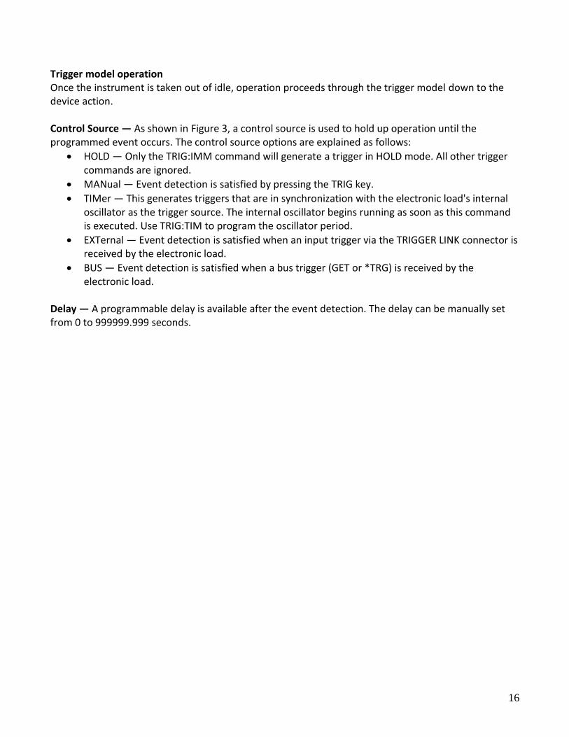
Trigger model operation Once the instrument is taken out of idle, operation proceeds through the trigger model down to the device action. Control Source — As shown in Figure 3, a control source is used to hold up operation until the programmed event occurs. The control source options are explained as follows:
HOLD — Only the TRIG:IMM command will generate a trigger in HOLD mode. All other trigger commands are ignored.
MANual — Event detection is satisfied by pressing the TRIG key.
TIMer — This generates triggers that are in synchronization with the electronic load's internal oscillator as the trigger source. The internal oscillator begins running as soon as this command is executed. Use TRIG:TIM to program the oscillator period.
EXTernal — Event detection is satisfied when an input trigger via the TRIGGER LINK connector is received by the electronic load.
BUS — Event detection is satisfied when a bus trigger (GET or *TRG) is received by the electronic load.
Delay — A programmable delay is available after the event detection. The delay can be manually set from 0 to 999999.999 seconds.
17
Chapter 2
Introduction to SCPI
SCPI (Standard Commands for Programmable Instruments) is a programming language for controlling instrument functions over GPIB, RS-232, USB, and Ethernet interface. SCPI is layered on top of the hardware portion of IEEE 488.2. The same SCPI commands and parameters control the same functions in different classes of instruments.
Conventions Used in This Guide Angle brackets < > Items within angle brackets are parameter abbreviations. For example,
<NR1> indicates a specific form of numerical data. Vertical bar | Vertical bars separate alternative parameters. For example, NORM | TEXT
indicates that either "NORM" or "TEXT" can be used as a parameter.
Square Brackets [ ] Items within square brackets are optional. The representation [SOURce:] VOLTage means that SOURce: may be omitted.
Braces { } Braces indicate parameters that may be repeated zero or more times. It is used especially for showing arrays. The notation <A>{<,B>} shows that parameter "A" must be entered, while parameter "B" may be omitted or may be entered one or more times.
2.1 Types of SCPI Commands SCPI has two types of commands, common and subsystem.
Common:
Common commands generally are not related to specific operation but to controlling overall electronic load functions, such as reset, status, and synchronization. All common commands consist of a three-letter mnemonic preceded by an asterisk (ex:*RST, *IDN?, *SRE 8).
Subsystem:
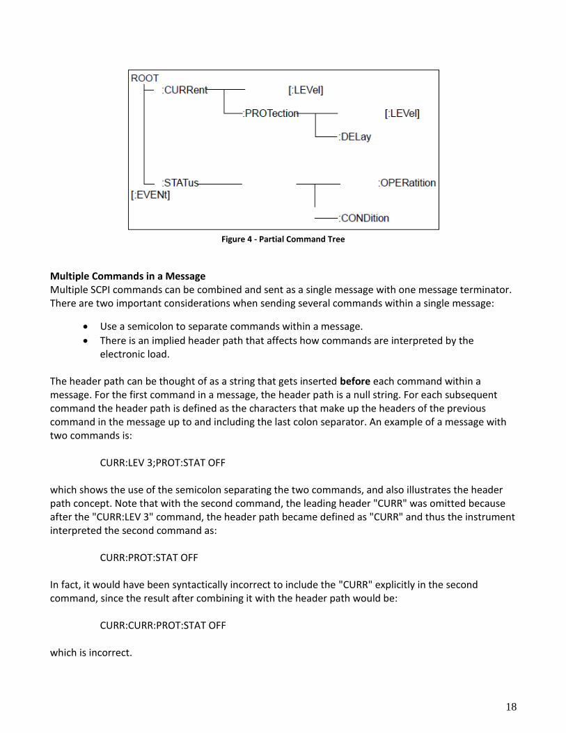
Subsystem commands perform specific electronic load functions. They are organized into an inverted tree structure with the "root" at the top. The following figure shows a portion of a subsystem command tree, from which you access the commands located along the various paths.
18
Figure 4 - Partial Command Tree
Multiple Commands in a Message Multiple SCPI commands can be combined and sent as a single message with one message terminator. There are two important considerations when sending several commands within a single message:
Use a semicolon to separate commands within a message.
There is an implied header path that affects how commands are interpreted by the electronic load.
The header path can be thought of as a string that gets inserted before each command within a message. For the first command in a message, the header path is a null string. For each subsequent command the header path is defined as the characters that make up the headers of the previous command in the message up to and including the last colon separator. An example of a message with two commands is:
CURR:LEV 3;PROT:STAT OFF
which shows the use of the semicolon separating the two commands, and also illustrates the header path concept. Note that with the second command, the leading header "CURR" was omitted because after the "CURR:LEV 3" command, the header path became defined as "CURR" and thus the instrument interpreted the second command as:
CURR:PROT:STAT OFF
In fact, it would have been syntactically incorrect to include the "CURR" explicitly in the second command, since the result after combining it with the header path would be:
CURR:CURR:PROT:STAT OFF
which is incorrect.
19
Moving Among Subsystems
In order to combine commands from different subsystems, you need to be able to reset the header path to a null string within a message. You do this by beginning the command with a colon (:), which discards any previous header path. For example, you could clear the output protection and check the status of the Operation Condition register in one message by using a root specifier as follows:
PROTection:CLEAr; :STATus:OPERation:CONDition?
The following message shows how to combine commands from different subsystems as well as within the same subsystem:
POWer:LEVel 200; PROTection 28; : CURRent: LEVel 3; PROTection:STATe ON Observe the use of the optional header LEVel to maintain the correct path within the voltage and current subsystems, and the use of the root specifier to move between subsystems.
Including Common Commands You can combine common commands with subsystem commands in the same message. Treat the common command as a message unit by separating it with a semicolon (the message unit separator). Common commands do not affect the header path; you may insert them anywhere in the message.
VOLTage 17.5;*TRG OUTPut OFF;*RCL 2;OUTPut ON
Case Sensitivity Common commands and SCPI commands are not case sensitive. You can use upper or lower case and any case combination. Example:
*RST = *rst :DATA? = :data? :SYSTem:PRESet = :system:preset
Long-form and Short-form Versions A SCPI command word can be sent in its long-form or short-form version. The command subsystem tables in Chapter 3 provide the long-form version. However, the short-form version is indicated by upper case characters. Example:
:SYSTem:PRESet (long-form) :SYST:PRES (short form) :SYSTem:PRES (long-form and short-form combination)
20
Note: Each command word must be in long-form or short-form, and not something in between. For example, :SYSTe:PRESe is illegal and will generate an error. The command will not be executed.
Using Queries Observe the following precautions with queries:
Set up the proper number of variables for the returned data. For example, if you are reading back a measurement array, you must dimension the array according to the number of measurements that you have placed in the measurement buffer.
Read back all the results of a query before sending another command to the electronic load. Otherwise a Query Interrupted error will occur and the unreturned data will be lost.
2.2 Types of SCPI Messages There are two types of SCPI messages, program and response.
1) A program message consists of one or more properly formatted SCPI commands sent from the controller to the electronic load. The message, which may be sent at any time, requests the electronic load to perform some action.
2) A response message consists of data in a specific SCPI format sent from the electronic load to the controller. The electronic load sends the message only when commanded by a program message called a "query."
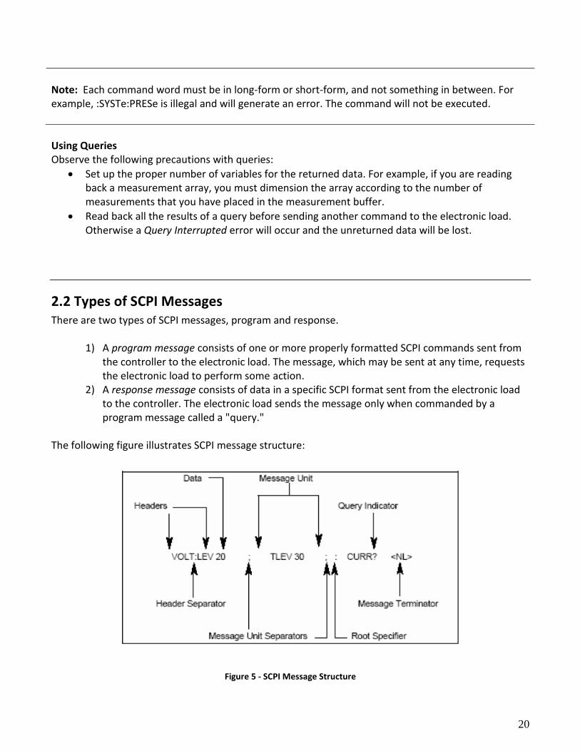
The following figure illustrates SCPI message structure:
Figure 5 - SCPI Message Structure
21
Message Unit The simplest SCPI command is a single message unit consisting of a command header (or keyword) followed by a message terminator. The message unit may include a parameter after the header. The parameter can be numeric or a string.
VOLTage 20<NL>
Headers Headers, also referred to as keywords, are instructions recognized by the electronic load. Headers may be either in the long-form or the short-form. In the long-form, the header is completely spelled out, such as VOLTAGE, STATUS, and DELAY. In the short form, the header has only the first three or four letters, such as VOLT, STAT, and DEL. Query Indicator Following a header with a question mark turns it into a query.
VOLTage?, CURRent:PROTection? If a query contains a parameter, place the query indicator at the end of the last header.
CURRent:PROTection? MAX
Message Unit Separator When two or more message units are combined into a compound message, separate the units with a semicolon. STATus:OPERation?;QUEStionable? Root Specifier When it precedes the first header of a message unit, the colon becomes the root specifier. It tells the command parser that this is the root or the top node of the command tree.
Message Terminator A terminator informs SCPI that it has reached the end of a message. Three permitted message terminators are:
1. Newline (<NL>), which is ASCII decimal 10 or hex 0A.
2. End or identify (<END>). 3. Both of the above (<NL><END>).
In the examples of this guide, there is an assumed message terminator at the end of each message.
22
Command Execution Rules
Commands execute in the order that they are presented in the program message.
An invalid command generates an error and is not executed.
Valid commands that precede an invalid command in a multiple command program message are executed.
Valid commands that follow an invalid command in a multiple command program message are ignored.
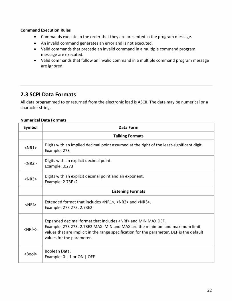
2.3 SCPI Data Formats All data programmed to or returned from the electronic load is ASCII. The data may be numerical or a character string.
Numerical Data Formats
Symbol Data Form
Talking Formats
<NR1> Digits with an implied decimal point assumed at the right of the least-significant digit. Example: 273
<NR2> Digits with an explicit decimal point. Example: .0273
<NR3> Digits with an explicit decimal point and an exponent. Example: 2.73E+2
Listening Formats
<NRf> Extended format that includes <NR1>, <NR2> and <NR3>. Example: 273 273. 2.73E2
<NRf+>
Expanded decimal format that includes <NRf> and MIN MAX DEF. Example: 273 273. 2.73E2 MAX. MIN and MAX are the minimum and maximum limit values that are implicit in the range specification for the parameter. DEF is the default values for the parameter.
<Bool> Boolean Data. Example: 0 | 1 or ON | OFF
23
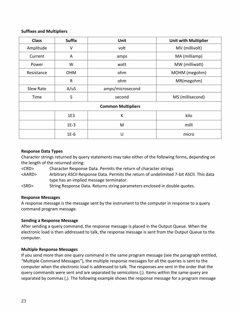
Suffixes and Multipliers
Class Suffix Unit Unit with Multiplier
Amplitude V volt MV (millivolt)
Current A amps MA (milliamp)
Power W watt MW (milliwatt)
Resistance OHM ohm MOHM (megohm)
R ohm MR(megohm)
Slew Rate A/uS amps/microsecond
Time S second MS (millisecond)
Common Multipliers
1E3 K kilo
1E-3 M milli
1E-6 U micro
Response Data Types Character strings returned by query statements may take either of the following forms, depending on the length of the returned string: <CRD> Character Response Data. Permits the return of character strings. <AARD> Arbitrary ASCII Response Data. Permits the return of undelimited 7-bit ASCII. This data
type has an implied message terminator. <SRD> String Response Data. Returns string parameters enclosed in double quotes. Response Messages A response message is the message sent by the instrument to the computer in response to a query command program message. Sending a Response Message After sending a query command, the response message is placed in the Output Queue. When the electronic load is then addressed to talk, the response message is sent from the Output Queue to the computer. Multiple Response Messages If you send more than one query command in the same program message (see the paragraph entitled, “Multiple Command Messages”), the multiple response messages for all the queries is sent to the computer when the electronic load is addressed to talk. The responses are sent in the order that the query commands were sent and are separated by semicolons (;). Items within the same query are separated by commas (,). The following example shows the response message for a program message
24
that contains four single item query commands:
0; 1; 1; 0 Response Message Terminator (RMT) Each response is terminated with an LF (line feed) and EOI (end or identify). The following example shows how a multiple response message is terminated:
0; 1; 1; 0; <RMT>
Message Exchange Protocol Two rules summarize the message exchange protocol:
Rule 1. You must always tell the electronic load what to send to the computer.
The following two steps must always be performed to send information from the computer to the instrument: 1) Send the appropriate query command(s) in a program message.
2) Address the electronic load to talk.
Rule 2. The complete response message must be received by the computer before another
program message can be sent to the electronic load.
2.4 SCPI Command Completion SCPI commands sent to the electronic load are processed either sequentially or in parallel. Sequential commands finish execution before a subsequent command begins. Parallel commands allow other commands to begin executing while the parallel command is still executing. Commands that affect trigger actions are among the parallel commands. The *WAI, *OPC, and *OPC? common commands provide different ways of indicating when all transmitted commands, including any parallel ones, have completed their operations. The syntax and parameters for these commands are described in Chapter 4. Some practical considerations for using these commands are as follows:
*WAI This prevents the electronic load from processing subsequent commands until all pending operations are completed.
*OPC? This places a 1 in the Output Queue when all pending operations have completed. Since it
requires your program to read the returned value before executing the next program statement, *OPC? can be used to cause the controller to wait for commands to complete before proceeding with its program.
25
*OPC This sets the OPC status bit when all pending operations have completed. Since your
program can read this status bit on an interrupt basis, *OPC allows subsequent commands to be executed.
NOTE: The trigger system must be in the Idle state in order for the status OPC bit to be true. Therefore, as far as triggers are concerned, OPC is false whenever the trigger system is in the Initiated state.
Using Device Clear You can send a device clear at any time to abort a SCPI command that may be hanging up the GPIB interface. The status registers, error queue, and all configuration states are left unchanged when a device clear message is received. Device clear performs the following actions:
The input and output buffers of the electronic load are cleared.
The electronic load is prepared to accept a new command string.
The following statement shows how to send a device clear over the GPIB interface using GW BASIC:
CLEAR 705 IEEE-488 Device Clear The following statement shows how to send a device clear over the GPIB interface using the GPIB command library for C or QuickBASIC:
IOCLEAR (705)
26
Chapter 3
SCPI Commands This chapter explains in detail the SCPI commands used by the electronic load. The electronic load conforms to SCPI Version 1995.0.
3.1 Language Dictionary
This section describes the syntax and parameters for all the IEEE 488.2 SCPI subsystem and common commands used by the electronic loads. Since the SCPI syntax remains the same for all programming languages, the examples given for each command are generic.
Syntax Forms Syntax definitions use the long form, but only short form headers (or "keywords") appear in the examples. Use the long form to help make your program self-documenting.
Parameters
Most commands require a parameter and all queries will return a parameter. The range for a parameter may vary according to the model of electronic load. Parameters for all models are listed in the Specifications table in the User’s Guide.
Related Commands
Where appropriate, related commands or queries are included. These are listed because they are either directly related by function, or because reading about them will clarify or enhance your understanding of the original command or query.
Order of Presentation
The dictionary is organized as follows:
Subsystem commands, arranged by subsystem
IEEE 488.2 common commands
Common Commands Common commands begin with an * and consist of three letters (command) or three letters and a ? (query). They are defined by the IEEE 488.2 standard to perform common interface functions. Common commands and queries are categorized under System, Status, or Trigger functions and are listed at the end of this chapter. Subsystem Commands Subsystem commands are specific to functions. They can be a single command or a group of
27
commands. The groups are comprised of commands that extend one or more levels below the root. The subsystem command groups are arranged according to function: Calibration, Input, List, Measurement, Port, Status, System, Transient, and Trigger. Commands under each function are grouped alphabetically under the subsystem. Commands followed by a question mark (?) take only the query form. When commands take both the command and query form, this is noted in the syntax descriptions.
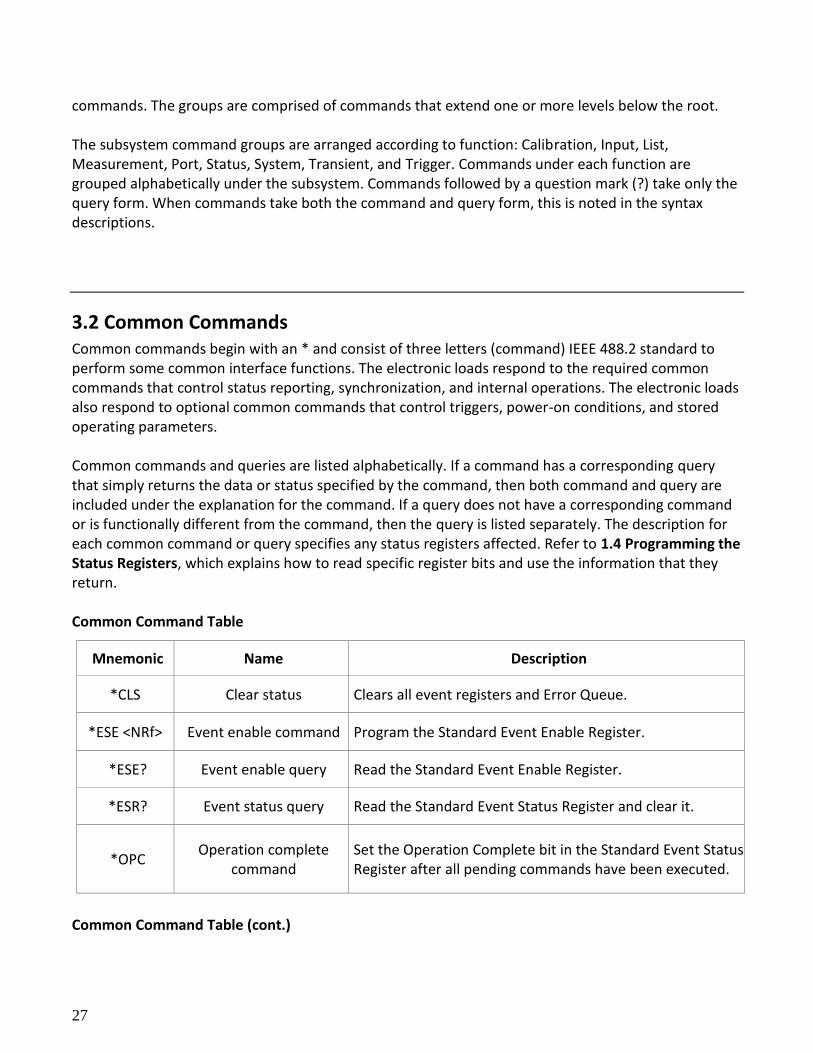
3.2 Common Commands Common commands begin with an * and consist of three letters (command) IEEE 488.2 standard to perform some common interface functions. The electronic loads respond to the required common commands that control status reporting, synchronization, and internal operations. The electronic loads also respond to optional common commands that control triggers, power-on conditions, and stored operating parameters. Common commands and queries are listed alphabetically. If a command has a corresponding query that simply returns the data or status specified by the command, then both command and query are included under the explanation for the command. If a query does not have a corresponding command or is functionally different from the command, then the query is listed separately. The description for each common command or query specifies any status registers affected. Refer to 1.4 Programming the Status Registers, which explains how to read specific register bits and use the information that they return. Common Command Table
Mnemonic Name Description
*CLS Clear status Clears all event registers and Error Queue.
*ESE <NRf> Event enable command Program the Standard Event Enable Register.
*ESE? Event enable query Read the Standard Event Enable Register.
*ESR? Event status query Read the Standard Event Status Register and clear it.
*OPC Operation complete
command Set the Operation Complete bit in the Standard Event Status Register after all pending commands have been executed.
Common Command Table (cont.)
28
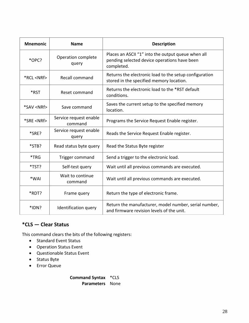
*CLS — Clear Status
This command clears the bits of the following registers:
Standard Event Status
Operation Status Event
Questionable Status Event
Status Byte
Error Queue
Command Syntax *CLS Parameters None
Mnemonic Name Description
*OPC? Operation complete
query
Places an ASCII “1” into the output queue when all pending selected device operations have been completed.
*RCL <NRf> Recall command Returns the electronic load to the setup configuration stored in the specified memory location.
*RST Reset command Returns the electronic load to the *RST default conditions.
*SAV <NRf> Save command Saves the current setup to the specified memory location.
*SRE <NRf> Service request enable
command Programs the Service Request Enable register.
*SRE? Service request enable
query Reads the Service Request Enable register.
*STB? Read status byte query Read the Status Byte register
*TRG Trigger command Send a trigger to the electronic load.
*TST? Self-test query Wait until all previous commands are executed.
*WAI Wait to continue
command Wait until all previous commands are executed.
*RDT? Frame query Return the type of electronic frame.
*IDN? Identification query Return the manufacturer, model number, serial number, and firmware revision levels of the unit.
29
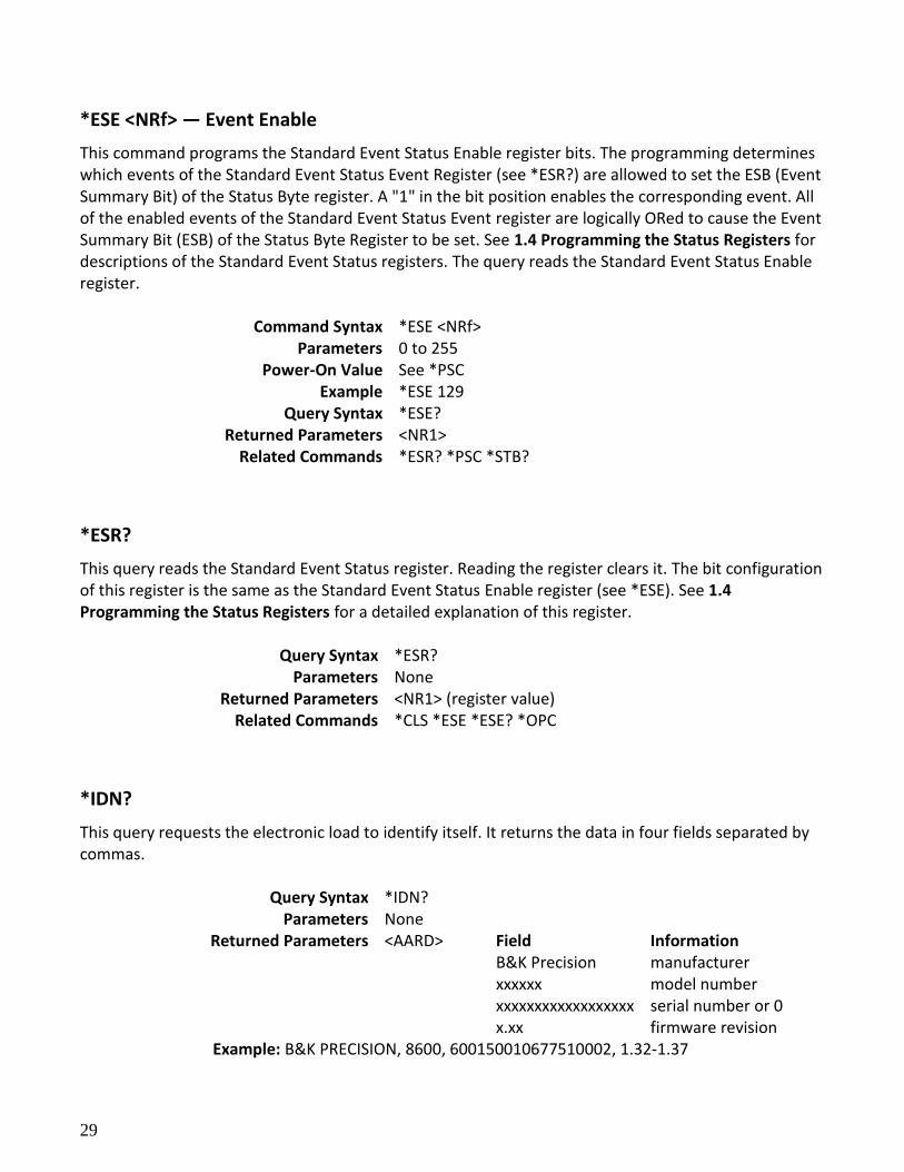
*ESE <NRf> — Event Enable
This command programs the Standard Event Status Enable register bits. The programming determines which events of the Standard Event Status Event Register (see *ESR?) are allowed to set the ESB (Event Summary Bit) of the Status Byte register. A "1" in the bit position enables the corresponding event. All of the enabled events of the Standard Event Status Event register are logically ORed to cause the Event Summary Bit (ESB) of the Status Byte Register to be set. See 1.4 Programming the Status Registers for descriptions of the Standard Event Status registers. The query reads the Standard Event Status Enable register.
Command Syntax *ESE <NRf> Parameters 0 to 255
Power-On Value See *PSC Example *ESE 129
Query Syntax *ESE? Returned Parameters <NR1>
Related Commands *ESR? *PSC *STB?
*ESR?
This query reads the Standard Event Status register. Reading the register clears it. The bit configuration of this register is the same as the Standard Event Status Enable register (see *ESE). See 1.4 Programming the Status Registers for a detailed explanation of this register.
Query Syntax *ESR? Parameters None
Returned Parameters <NR1> (register value) Related Commands *CLS *ESE *ESE? *OPC
*IDN?
This query requests the electronic load to identify itself. It returns the data in four fields separated by commas.
Query Syntax *IDN? Parameters None
Returned Parameters <AARD> Field Information B&K Precision manufacturer xxxxxx model number xxxxxxxxxxxxxxxxxx serial number or 0 x.xx firmware revision
Example: B&K PRECISION, 8600, 600150010677510002, 1.32-1.37
30
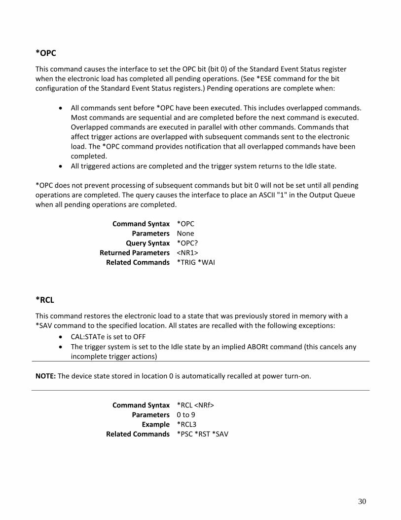
*OPC
This command causes the interface to set the OPC bit (bit 0) of the Standard Event Status register when the electronic load has completed all pending operations. (See *ESE command for the bit configuration of the Standard Event Status registers.) Pending operations are complete when:
All commands sent before *OPC have been executed. This includes overlapped commands. Most commands are sequential and are completed before the next command is executed. Overlapped commands are executed in parallel with other commands. Commands that affect trigger actions are overlapped with subsequent commands sent to the electronic load. The *OPC command provides notification that all overlapped commands have been completed.
All triggered actions are completed and the trigger system returns to the Idle state. *OPC does not prevent processing of subsequent commands but bit 0 will not be set until all pending operations are completed. The query causes the interface to place an ASCII "1" in the Output Queue when all pending operations are completed.
Command Syntax *OPC Parameters None
Query Syntax *OPC? Returned Parameters <NR1>
Related Commands *TRIG *WAI
*RCL
This command restores the electronic load to a state that was previously stored in memory with a *SAV command to the specified location. All states are recalled with the following exceptions:
CAL:STATe is set to OFF
The trigger system is set to the Idle state by an implied ABORt command (this cancels any incomplete trigger actions)
NOTE: The device state stored in location 0 is automatically recalled at power turn-on.
Command Syntax *RCL <NRf>
Parameters 0 to 9 Example *RCL3
Related Commands *PSC *RST *SAV
31
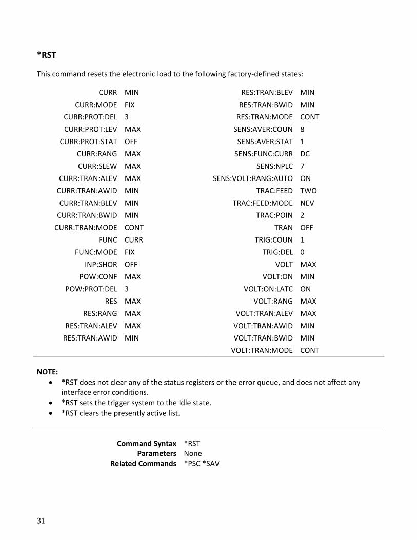
*RST
This command resets the electronic load to the following factory-defined states:
CURR MIN RES:TRAN:BLEV MIN
CURR:MODE FIX RES:TRAN:BWID MIN
CURR:PROT:DEL 3 RES:TRAN:MODE CONT
CURR:PROT:LEV MAX SENS:AVER:COUN 8
CURR:PROT:STAT OFF SENS:AVER:STAT 1
CURR:RANG MAX SENS:FUNC:CURR DC
CURR:SLEW MAX SENS:NPLC 7
CURR:TRAN:ALEV MAX SENS:VOLT:RANG:AUTO ON
CURR:TRAN:AWID MIN TRAC:FEED TWO
CURR:TRAN:BLEV MIN TRAC:FEED:MODE NEV
CURR:TRAN:BWID MIN TRAC:POIN 2
CURR:TRAN:MODE CONT TRAN OFF
FUNC CURR TRIG:COUN 1
FUNC:MODE FIX TRIG:DEL 0
INP:SHOR OFF VOLT MAX
POW:CONF MAX VOLT:ON MIN
POW:PROT:DEL 3 VOLT:ON:LATC ON
RES MAX VOLT:RANG MAX
RES:RANG MAX VOLT:TRAN:ALEV MAX
RES:TRAN:ALEV MAX VOLT:TRAN:AWID MIN
RES:TRAN:AWID MIN VOLT:TRAN:BWID MIN
VOLT:TRAN:MODE CONT
NOTE:
*RST does not clear any of the status registers or the error queue, and does not affect any interface error conditions.
*RST sets the trigger system to the Idle state.
*RST clears the presently active list.
Command Syntax *RST
Parameters None Related Commands *PSC *SAV
32
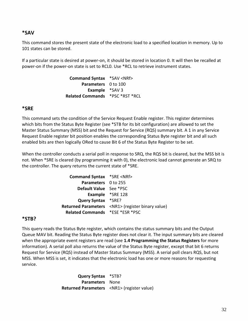
*SAV
This command stores the present state of the electronic load to a specified location in memory. Up to 101 states can be stored. If a particular state is desired at power-on, it should be stored in location 0. It will then be recalled at power-on if the power-on state is set to RCL0. Use *RCL to retrieve instrument states.
Command Syntax *SAV <NRf> Parameters 0 to 100
Example *SAV 3 Related Commands *PSC *RST *RCL
*SRE
This command sets the condition of the Service Request Enable register. This register determines which bits from the Status Byte Register (see *STB for its bit configuration) are allowed to set the Master Status Summary (MSS) bit and the Request for Service (RQS) summary bit. A 1 in any Service Request Enable register bit position enables the corresponding Status Byte register bit and all such enabled bits are then logically ORed to cause Bit 6 of the Status Byte Register to be set. When the controller conducts a serial poll in response to SRQ, the RQS bit is cleared, but the MSS bit is not. When *SRE is cleared (by programming it with 0), the electronic load cannot generate an SRQ to the controller. The query returns the current state of *SRE.
Command Syntax *SRE <NRf> Parameters 0 to 255
Default Value See *PSC Example *SRE 128
Query Syntax *SRE? Returned Parameters <NR1> (register binary value)
Related Commands *ESE *ESR *PSC
*STB?
This query reads the Status Byte register, which contains the status summary bits and the Output Queue MAV bit. Reading the Status Byte register does not clear it. The input summary bits are cleared when the appropriate event registers are read (see 1.4 Programming the Status Registers for more information). A serial poll also returns the value of the Status Byte register, except that bit 6 returns Request for Service (RQS) instead of Master Status Summary (MSS). A serial poll clears RQS, but not MSS. When MSS is set, it indicates that the electronic load has one or more reasons for requesting service.
Query Syntax *STB? Parameters None
Returned Parameters <NR1> (register value)
33
Related Commands *SRE *ESR *ESE
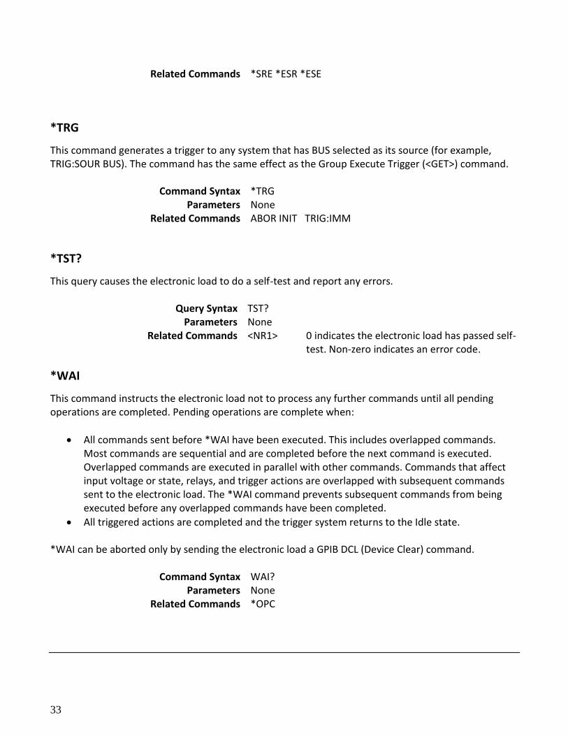
*TRG
This command generates a trigger to any system that has BUS selected as its source (for example, TRIG:SOUR BUS). The command has the same effect as the Group Execute Trigger (<GET>) command.
Command Syntax *TRG Parameters None
Related Commands ABOR INIT TRIG:IMM
*TST?
This query causes the electronic load to do a self-test and report any errors.
Query Syntax TST? Parameters None
Related Commands <NR1> 0 indicates the electronic load has passed self-test. Non-zero indicates an error code.
*WAI
This command instructs the electronic load not to process any further commands until all pending operations are completed. Pending operations are complete when:
All commands sent before *WAI have been executed. This includes overlapped commands. Most commands are sequential and are completed before the next command is executed. Overlapped commands are executed in parallel with other commands. Commands that affect input voltage or state, relays, and trigger actions are overlapped with subsequent commands sent to the electronic load. The *WAI command prevents subsequent commands from being executed before any overlapped commands have been completed.
All triggered actions are completed and the trigger system returns to the Idle state.
*WAI can be aborted only by sending the electronic load a GPIB DCL (Device Clear) command.
Command Syntax WAI? Parameters None
Related Commands *OPC
34
3.3 Subsystem Commands
The following is a list of the SCPI subsystem commands and the table number where each command is summarized.
Trigger Commands
System Commands
Status Commands
Trace Commands
Source Commands
List Commands
Measure Commands
Sense Commands
Calibrate Commands
General notes:
Brackets ([ ]) are used to denote optional character sets. These optional characters do not have to be included in the program message. Do not use brackets in the program message.
Angle brackets (< >) are used to indicate parameter type. Do not use angle brackets in the program message.
The Boolean parameter (<b>) is used to enable or disable an instrument operation. 1 or ON enables the operation and 0 or OFF disables the operation.
Upper case characters indicate the short-form version for each command word.
Default Parameter — Listed parameters are both the *RST and :SYSTem:PRESet defaults, unless noted otherwise. Parameter notes are located at the end of each table.
Trigger Commands
The trigger subsystem is made up of a series of commands and subsystems to configure the trigger model.
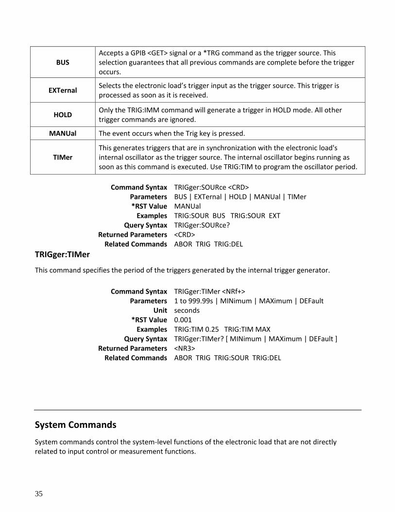
TRIGger:SOURce
This command selects the trigger source.
35
BUS Accepts a GPIB <GET> signal or a *TRG command as the trigger source. This selection guarantees that all previous commands are complete before the trigger occurs.
EXTernal Selects the electronic load’s trigger input as the trigger source. This trigger is processed as soon as it is received.
HOLD Only the TRIG:IMM command will generate a trigger in HOLD mode. All other trigger commands are ignored.
MANUal The event occurs when the Trig key is pressed.
TIMer This generates triggers that are in synchronization with the electronic load's internal oscillator as the trigger source. The internal oscillator begins running as soon as this command is executed. Use TRIG:TIM to program the oscillator period.
Command Syntax TRIGger:SOURce <CRD> Parameters BUS | EXTernal | HOLD | MANUal | TIMer *RST Value MANUal
Examples TRIG:SOUR BUS TRIG:SOUR EXT Query Syntax TRIGger:SOURce?
Returned Parameters <CRD> Related Commands ABOR TRIG TRIG:DEL
TRIGger:TIMer
This command specifies the period of the triggers generated by the internal trigger generator.
Command Syntax TRIGger:TIMer <NRf+> Parameters 1 to 999.99s | MINimum | MAXimum | DEFault
Unit seconds *RST Value 0.001
Examples TRIG:TIM 0.25 TRIG:TIM MAX Query Syntax TRIGger:TIMer? [ MINimum | MAXimum | DEFault ]
Returned Parameters <NR3> Related Commands ABOR TRIG TRIG:SOUR TRIG:DEL
System Commands
System commands control the system-level functions of the electronic load that are not directly related to input control or measurement functions.
36
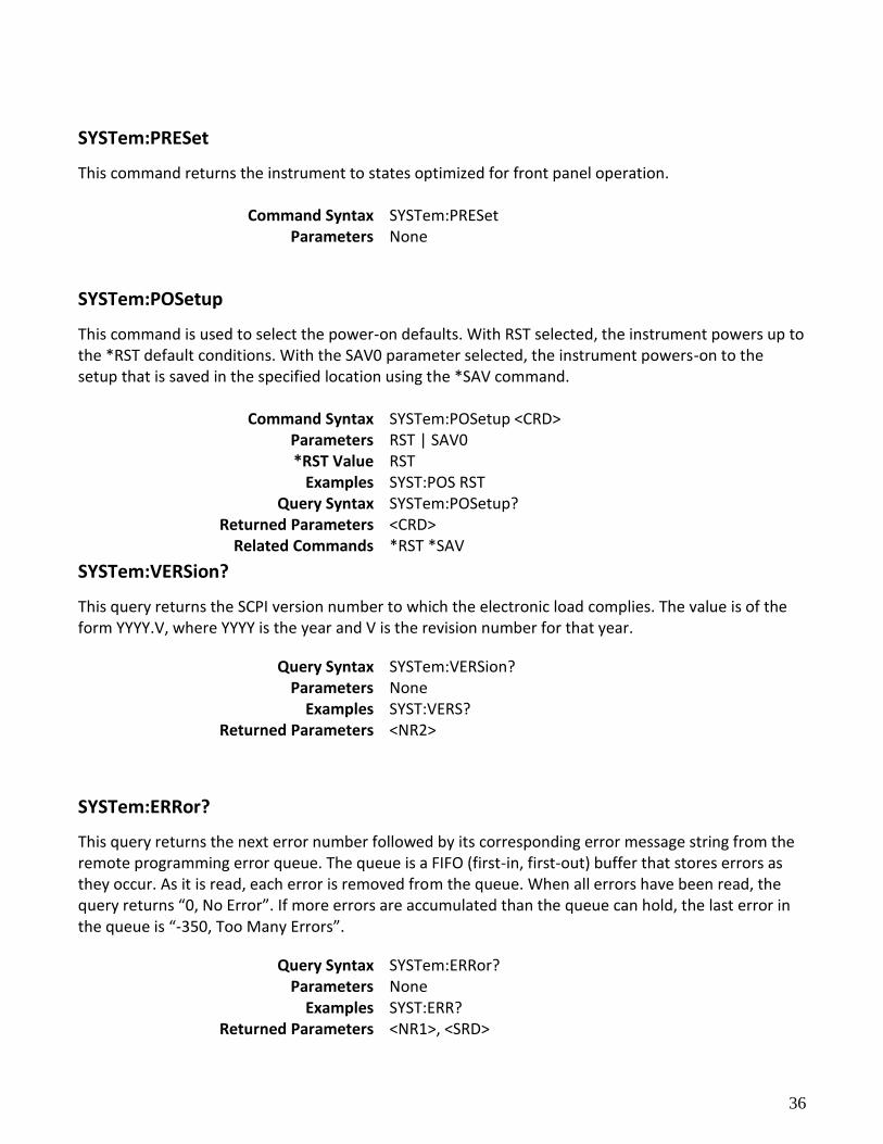
SYSTem:PRESet
This command returns the instrument to states optimized for front panel operation.
Command Syntax SYSTem:PRESet Parameters None
SYSTem:POSetup
This command is used to select the power-on defaults. With RST selected, the instrument powers up to the *RST default conditions. With the SAV0 parameter selected, the instrument powers-on to the setup that is saved in the specified location using the *SAV command.
Command Syntax SYSTem:POSetup <CRD> Parameters RST | SAV0 *RST Value RST
Examples SYST:POS RST Query Syntax SYSTem:POSetup?
Returned Parameters <CRD> Related Commands *RST *SAV
SYSTem:VERSion?
This query returns the SCPI version number to which the electronic load complies. The value is of the form YYYY.V, where YYYY is the year and V is the revision number for that year.
Query Syntax SYSTem:VERSion? Parameters None
Examples SYST:VERS? Returned Parameters <NR2>
SYSTem:ERRor?
This query returns the next error number followed by its corresponding error message string from the remote programming error queue. The queue is a FIFO (first-in, first-out) buffer that stores errors as they occur. As it is read, each error is removed from the queue. When all errors have been read, the query returns “0, No Error”. If more errors are accumulated than the queue can hold, the last error in the queue is “-350, Too Many Errors”.
Query Syntax SYSTem:ERRor? Parameters None
Examples SYST:ERR? Returned Parameters <NR1>, <SRD>
37
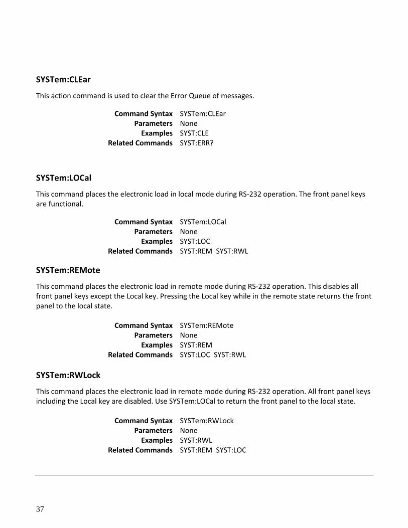
SYSTem:CLEar
This action command is used to clear the Error Queue of messages.
Command Syntax SYSTem:CLEar Parameters None
Examples SYST:CLE Related Commands SYST:ERR?
SYSTem:LOCal
This command places the electronic load in local mode during RS-232 operation. The front panel keys are functional.
Command Syntax SYSTem:LOCal Parameters None
Examples SYST:LOC Related Commands SYST:REM SYST:RWL
SYSTem:REMote
This command places the electronic load in remote mode during RS-232 operation. This disables all front panel keys except the Local key. Pressing the Local key while in the remote state returns the front panel to the local state.
Command Syntax SYSTem:REMote Parameters None
Examples SYST:REM Related Commands SYST:LOC SYST:RWL
SYSTem:RWLock
This command places the electronic load in remote mode during RS-232 operation. All front panel keys including the Local key are disabled. Use SYSTem:LOCal to return the front panel to the local state.
Command Syntax SYSTem:RWLock Parameters None
Examples SYST:RWL Related Commands SYST:REM SYST:LOC
38
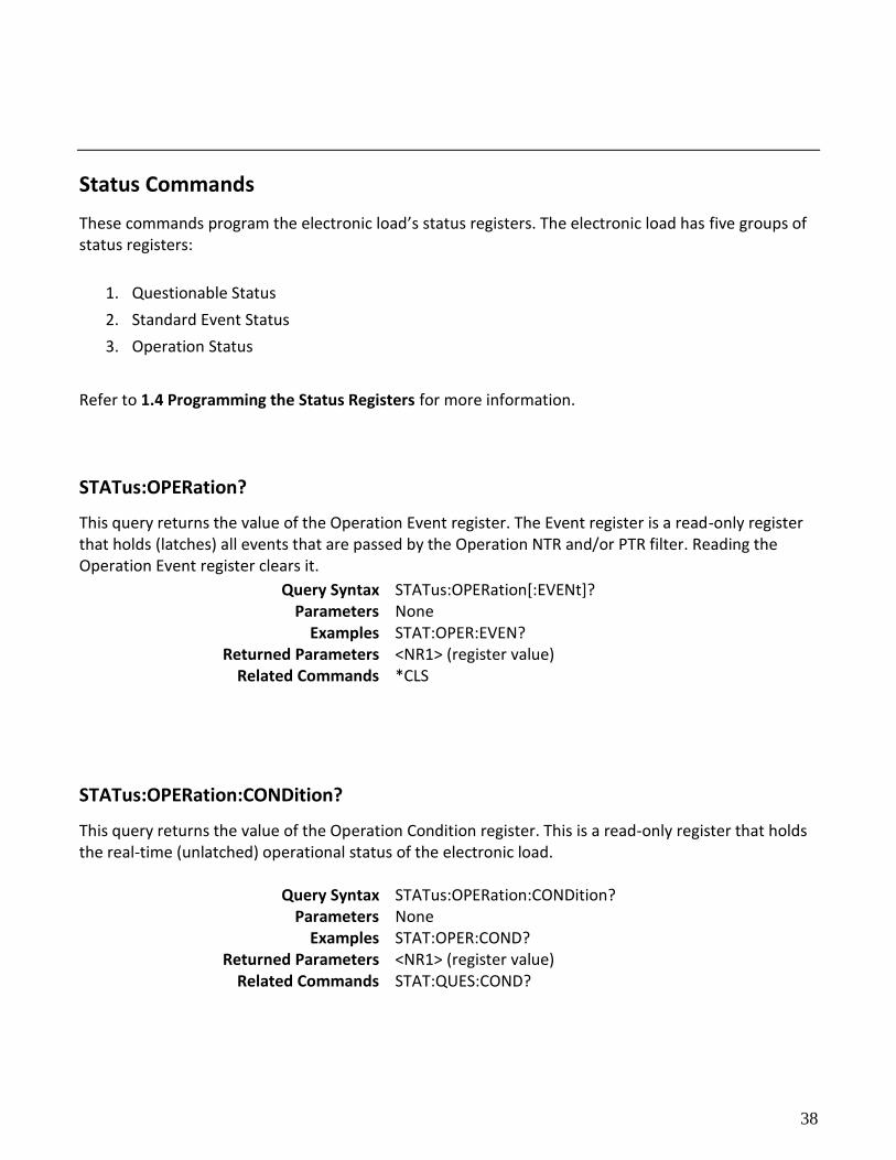
Status Commands
These commands program the electronic load’s status registers. The electronic load has five groups of status registers:
1. Questionable Status
2. Standard Event Status
3. Operation Status
Refer to 1.4 Programming the Status Registers for more information.
STATus:OPERation?
This query returns the value of the Operation Event register. The Event register is a read-only register that holds (latches) all events that are passed by the Operation NTR and/or PTR filter. Reading the Operation Event register clears it.
Query Syntax STATus:OPERation[:EVENt]? Parameters None
Examples STAT:OPER:EVEN? Returned Parameters <NR1> (register value)
Related Commands *CLS
STATus:OPERation:CONDition?
This query returns the value of the Operation Condition register. This is a read-only register that holds the real-time (unlatched) operational status of the electronic load.
Query Syntax STATus:OPERation:CONDition? Parameters None
Examples STAT:OPER:COND? Returned Parameters <NR1> (register value)
Related Commands STAT:QUES:COND?
39
STATus:OPERation:ENABle
This command and its query can be used to set and read the value of the Operation Enable register. This register is a mask for enabling specific bits from the Operation Event register to set the operation summary bit (OPER) of the Status Byte register. The operation summary bit is the logical OR of all enabled Operation Event register bits.
Command Syntax STATus:OPERation:ENABle <NR1> Parameters 0 to 65535
Default Value 0 Examples STAT:OPER:ENAB 32 STAT:OPER:ENAB 1
Query Syntax STATus:OPERation:ENABle? Returned Parameters <NR1> (register value)
Related Commands STAT:OPER?
STATus:QUEStionable?
This query returns the value of the Questionable Event register. The Event register is a read-only register that holds (latches) all events that pass into it. Reading the Questionable Event register clears it.
Query Syntax STATus:QUEStionable[:EVENt]? Parameters None
Examples STAT:QUES:EVEN? Returned Parameters <NR1> (register value)
STATus:QUEStionable:CONDition?
This query returns the value of the Questionable Condition register. This is a read-only register that holds the real-time (unlatched) questionable status of the electronic load.
Query Syntax STATus:QUEStionable:CONDition? Parameters None
Examples STAT:QUES:COND? Returned Parameters <NR1> (register value)
Related Commands STAT:OPER:COND?
STATus:QUEStionable:ENABle
40
This command sets or reads the value of the Questionable Enable register. This register is a mask for enabling specific bits from the Questionable Event register to set the questionable summary (QUES) bit of the Status Byte register. This bit (bit 3) is the logical OR of all the Questionable Event register bits that are enabled by the Questionable Status Enable register.
Command Syntax STATus:QUEStionable:ENABle <NR1>
Parameters 0 to 65535 Default Value 0
Examples STAT:QUES:ENAB 32 STAT:QUES:ENAB 1 Query Syntax STATus:QUEStionable:ENABle?
Returned Parameters <NR1> (register value) Related Commands STAT:QUES?
STATus:PRESet
When this command is sent, the SCPI event registers are affected as follows: All bits of the following registers are cleared to zero (0):
Questionable Event Enable Register
Operation Event Enable Register
NOTE: Registers not included in the list above are not affected by this command.
Command Syntax STATus:PRESet
Parameters None Examples STAT:PRES
Trace Commands
The commands in this subsystem are used to configure and control data storage into the buffer.
TRACe:CLEar
41
This action command is used to clear the buffer of readings. If you do not clear the buffer, a subsequent store will overwrite the old readings. If the subsequent store is aborted before the buffer becomes full, you could end up with some “old” readings still in the buffer.
Command Syntax TRACe:CLEar Parameters None
Example TRAC:CLE
TRACe:FREE?
This command is used to read the status of storage memory. After sending this command and addressing the electronic load to talk, two values separated by commas are sent to the computer. The first value indicates how many bytes of memory are available, and the second value indicates how many bytes are reserved to store readings.
Query Syntax TRACe:FREE? Returned Parameters <NR1>, <NR1>
Examples TRAC:FREE?
TRACe:POINts
This command is used to specify the size of the buffer.
Command Syntax TRACe:POINts <NRf+> Parameters 0 to 2000 | MINimum | MAXimum | DEFault *RST Value 2000
Examples TRAC:POIN 10 Query Syntax TRACe: POINts? [ MINimum | MAXimum | DEFault ]
Returned Parameters <NR1> Related Commands TRAC:FEED
TRACe:FEED
This command is used to select the source of readings to be placed in the buffer. With VOLTage selected, voltage readings are placed in the buffer (TRAC:POIN maximum value is 2000). With CURRent selected, current readings are placed in the buffer (TRAC:POIN maximum value is 2000). With TWO selected, voltage and current are placed in the buffer when storage is performed (TRAC:POIN maximum value is 100).
Command Syntax TRACe:FEED <CRD>
42
Parameters VOLTage | CURRent | TWO *RST Value TWO
Examples TRAC:FEED VOLT Query Syntax TRACe:FEED?
Returned Parameters <CRD> Related Commands TRAC:POIN
TRACe:FEED:CONTrol
This command is used to select the buffer control. With NEVer selected, storage into the buffer is disabled. When NEXT is selected, the storage process starts, fills the buffer and then stops. The buffer size is specified by the :POINts command.
Command Syntax TRACe:FEED:CONTrol <CRD> Parameters NEVer | NEXT *RST Value NEVer
Examples TRAC:FEED:CONT NEXT Query Syntax TRACe: FEED:CONT?
Returned Parameters <CRD> Related Commands TRAC:FEED
TRACe:DATA?
When this command is sent and the electronic load is addressed to talk, all the readings stored in the buffer are sent to the computer.
Query Syntax TRACe:DATA? Returned Parameters {<NR3>, <NR3>…etc,} or {<NR3> <NR3>, <NR3> <NR3>
…etc} (if TRACe:FEED TWO is set)
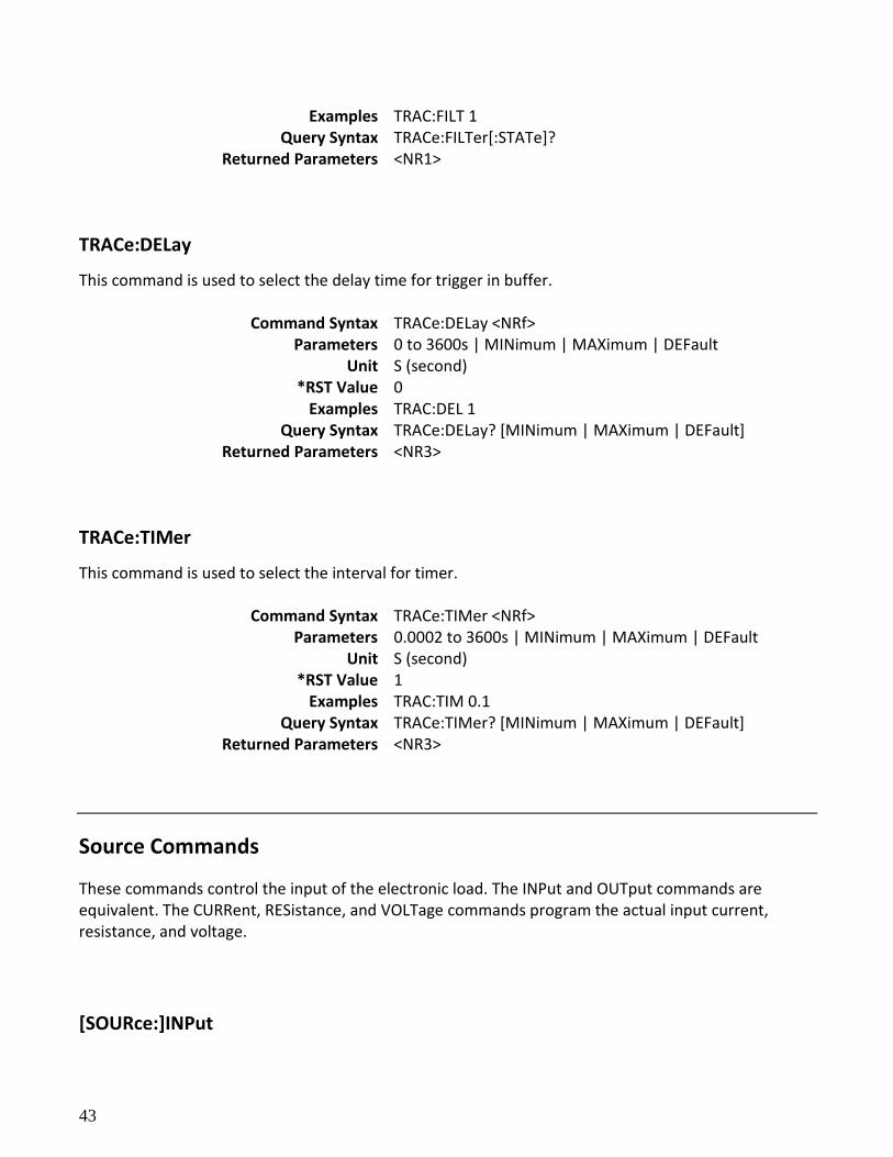
TRACe:FILTer
This command is used to select whether the data in buffer is filtered data.
Command Syntax TRACe:FILTer[:STATe] <BOOL> Parameters 0 | 1 | ON | OFF *RST Value OFF
43
Examples TRAC:FILT 1 Query Syntax TRACe:FILTer[:STATe]?
Returned Parameters <NR1>
TRACe:DELay
This command is used to select the delay time for trigger in buffer.
Command Syntax TRACe:DELay <NRf> Parameters 0 to 3600s | MINimum | MAXimum | DEFault
Unit S (second) *RST Value 0
Examples TRAC:DEL 1 Query Syntax TRACe:DELay? [MINimum | MAXimum | DEFault]
Returned Parameters <NR3>
TRACe:TIMer
This command is used to select the interval for timer.
Command Syntax TRACe:TIMer <NRf> Parameters 0.0002 to 3600s | MINimum | MAXimum | DEFault
Unit S (second) *RST Value 1
Examples TRAC:TIM 0.1 Query Syntax TRACe:TIMer? [MINimum | MAXimum | DEFault]
Returned Parameters <NR3>
Source Commands
These commands control the input of the electronic load. The INPut and OUTput commands are equivalent. The CURRent, RESistance, and VOLTage commands program the actual input current, resistance, and voltage.
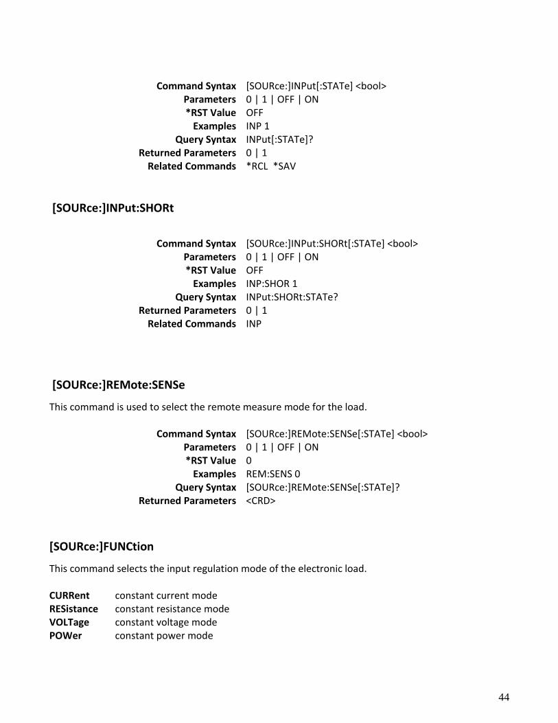
[SOURce:]INPut
44
Command Syntax [SOURce:]INPut[:STATe] <bool>
Parameters 0 | 1 | OFF | ON *RST Value OFF
Examples INP 1 Query Syntax INPut[:STATe]?
Returned Parameters 0 | 1 Related Commands *RCL *SAV
[SOURce:]INPut:SHORt
Command Syntax [SOURce:]INPut:SHORt[:STATe] <bool>
Parameters 0 | 1 | OFF | ON *RST Value OFF
Examples INP:SHOR 1 Query Syntax INPut:SHORt:STATe?
Returned Parameters 0 | 1 Related Commands INP
[SOURce:]REMote:SENSe
This command is used to select the remote measure mode for the load.
Command Syntax [SOURce:]REMote:SENSe[:STATe] <bool> Parameters 0 | 1 | OFF | ON *RST Value 0
Examples REM:SENS 0 Query Syntax [SOURce:]REMote:SENSe[:STATe]?
Returned Parameters <CRD>
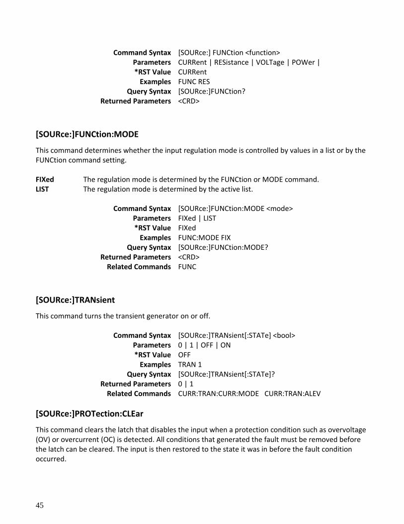
[SOURce:]FUNCtion
This command selects the input regulation mode of the electronic load. CURRent constant current mode RESistance constant resistance mode VOLTage constant voltage mode POWer constant power mode
45
Command Syntax [SOURce:] FUNCtion <function> Parameters CURRent | RESistance | VOLTage | POWer | *RST Value CURRent
Examples FUNC RES Query Syntax [SOURce:]FUNCtion?
Returned Parameters <CRD>
[SOURce:]FUNCtion:MODE
This command determines whether the input regulation mode is controlled by values in a list or by the FUNCtion command setting. FIXed The regulation mode is determined by the FUNCtion or MODE command. LIST The regulation mode is determined by the active list.
Command Syntax [SOURce:]FUNCtion:MODE <mode> Parameters FIXed | LIST *RST Value FIXed
Examples FUNC:MODE FIX Query Syntax [SOURce:]FUNCtion:MODE?
Returned Parameters <CRD> Related Commands FUNC
[SOURce:]TRANsient
This command turns the transient generator on or off.
Command Syntax [SOURce:]TRANsient[:STATe] <bool> Parameters 0 | 1 | OFF | ON *RST Value OFF
Examples TRAN 1 Query Syntax [SOURce:]TRANsient[:STATe]?
Returned Parameters 0 | 1 Related Commands CURR:TRAN:CURR:MODE CURR:TRAN:ALEV
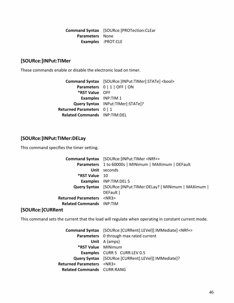
[SOURce:]PROTection:CLEar
This command clears the latch that disables the input when a protection condition such as overvoltage (OV) or overcurrent (OC) is detected. All conditions that generated the fault must be removed before the latch can be cleared. The input is then restored to the state it was in before the fault condition occurred.
46
Command Syntax [SOURce:]PROTection:CLEar Parameters None
Examples :PROT:CLE
[SOURce:]INPut:TIMer
These commands enable or disable the electronic load on timer.
Command Syntax [SOURce:]INPut:TIMer[:STATe] <bool> Parameters 0 | 1 | OFF | ON *RST Value OFF
Examples INP:TIM 1 Query Syntax INPut:TIMer[:STATe]?
Returned Parameters 0 | 1 Related Commands INP:TIM:DEL
[SOURce:]INPut:TIMer:DELay
This command specifies the timer setting.
Command Syntax [SOURce:]INPut:TIMer <NRf+> Parameters 1 to 60000s | MINimum | MAXimum | DEFault
Unit seconds *RST Value 10
Examples INP:TIM:DEL 5 Query Syntax [SOURce:]INPut:TIMer:DELay? [ MINimum | MAXimum |
DEFault ] Returned Parameters <NR3>
Related Commands INP:TIM
[SOURce:]CURRent
This command sets the current that the load will regulate when operating in constant current mode.
Command Syntax [SOURce:]CURRent[:LEVel][:IMMediate] <NRf+> Parameters 0 through max rated current
Unit A (amps) *RST Value MINimum
Examples CURR 5 CURR:LEV 0.5 Query Syntax [SOURce:]CURRent[:LEVel][:IMMediate]?
Returned Parameters <NR3> Related Commands CURR:RANG
47
[SOURce:]CURRent:RANGe
This command sets the current range of the electronic load module. There are two current ranges, high range (model dependent) and low range (model dependent). When you program a range value, the load automatically selects the range that corresponds to the value that you program. If the value falls in a region where ranges overlap, the electronic load selects the range with the highest resolution.
NOTE: When this command is executed, the IMMediate, TRANsient, TRIGgered, and SLEW current settings are adjusted as follows.
If existing settings are within new range, no adjustment is made.
If existing settings are outside new range, the levels are set to the maximum value of the new range.
Command Syntax [SOURce:]CURRent:RANGe <NRf+>
Parameters 0 through max. Rated current Unit A (amps)
*RST Value max. current (high range) Examples SOUR:CURR:RANGE 5
Query Syntax [SOURce:]CURRent:RANGe Returned Parameters <NR3>
Related Commands CURR CURR:SLEW
[SOURce:]CURRent:SLEW
This command sets the slew rate for all programmed changes in the input current level of the electronic load. This command programs both positive and negative slew rates. MAXimum sets the slew to the fastest possible rate. MINimum sets the slew to the slowest rate.
Command Syntax [SOURce:]CURRent:SLEW[:BOTH] <NRf+> Parameters See specifications
Unit A (amps per micro second) Examples CURR:SLEW MAX
Related Commands CURR CURR:NEG CURR:SLEW:POS
48
[SOURce:]CURRent:SLEW:POSitive
This command sets the slew rate of the current for positive transitions. MAXimum sets the slew to the fastest possible rate. MINimum sets the slew to the slowest rate.
Command Syntax [SOURce:]CURRent:SLEW:POSitive <NRf+> Parameters See specifications
Unit A (amps per micro second) Examples CURR:SLEW:POS 0.0001
Query Syntax [SOURce:]CURRent:SLEW:POSitive? Returned Parameters <NR3>
Related Commands CURR:SLEW
[SOURce:]CURRent:SLEW:NEGative
This command sets the slew rate of the current for negative transitions. MAXimum sets the slew to the fastest possible rate. MINimum sets the slew to the slowest rate.
Command Syntax [SOURce:]CURRent:SLEW:NEGative <NRf+> Parameters see specifications
Unit A (amps per micro second) Examples CURR:SLEW:NEG 0.0001
Query Syntax [SOURce:]CURRent:SLEW:NEGative? Returned Parameters <NR3>
Related Commands CURR:SLEW
[SOURce:]CURRent:PROTection:STATe
This command enables or disables the overcurrent protection feature.
Command Syntax [SOURce:]CURRent:PROTection:STATe <Bool> Parameters 0 | 1 | OFF | ON *RST Value OFF
Examples CURR:PROT:STAT 1 Query Syntax [SOURce:]CURRent:PROTection:STATe?
Returned Parameters <NR3> Related Commands CURR:PROT
[SOURce:]CURRent:PROTection
49
This command sets the soft current protection level. If the input current exceeds the soft current protection level for the time specified by CURR:PROT:DEL, the input is turned off.
NOTE: Use CURR:PROT:DEL to prevent momentary current limit conditions caused by programmed changes from tripping the overcurrent protection.
Command Syntax [SOURce:]CURRent:PROTection:LEVel <NRf+>
Parameters 0 through max. Rated current Unit A (amps)
Examples CURR:PROT 2 Query Syntax [SOURce:]CURRent:PROTection:LEVel?
Returned Parameters <NR3> Related Commands CURR:PROT:DEL CURR:PROT:STAT
[SOURce:]CURRent:PROTection:DELay
This command specifies the time that the input current can exceed the protection level before the input is turned off.
Command Syntax [SOURce:]CURRent:PROTection[:DELay] <NRf+> Parameters 0 to 60 seconds
Unit seconds *RST Value 0
Examples CURR:PROT:DEL 5 Query Syntax [SOURce:]CURRent:PROTection:DELay?
Returned Parameters <NR1> Related Commands CURR:PROT CURR:PROT:STAT
[SOURce:]CURRent:TRANsient:MODE
This command selects the operating mode of the transient generator as follows in constant current mode.
CONTinuous The transient generator puts out a continuous pulse stream after receipt of a trigger. PULSe The transient generator puts out a single pulse upon receipt of a trigger. TOGGle The transient generator toggles between two levels upon receipt of a trigger.
Command Syntax [SOURce:]CURRent:TRANsient:MODE <mode> Parameters CONTinuous | PULSe | TOGGle *RST Value CONTinuous
50
Examples CURR:TRAN:MODE TOGG Query Syntax [SOURce:]CURRent:TRANsient:MODE?
Returned Parameters <CRD> Related Commands CURR:TRAN:ALEV TRAN
[SOURce:]CURRent:TRANsient:ALEVel
[SOURce:]CURRent:TRANsient:BLEVel
These commands specify the transient level of the input current. The transient function switches between level A and level B.
Command Syntax [SOURce:]CURRent:TRANsient:ALEVel <NRf+> [SOURce:]CURRent:TRANsient:BLEVel <NRf+>
Parameters 0 through max. Rated current Unit A (amps)
Examples CURR:TRAN:ALEV 5 CURR:TRAN:BLEV 0.5 Query Syntax [SOURce:]CURRent:TRANsient:ALEVel?
[SOURce:]CURRent:TRANsient:BLEVel Returned Parameters <NR3>
Related Commands CURR:
[SOURce:]CURRent:TRANsient:AWIDth [SOURce:]CURRent:TRANsient:BWIDth
These commands specify the transient pulse width of the input current. The command takes 2 parameters, first is the time and second is the unit. Both the time and the units
must be specified. The numbers permitted also need to follow the following:
Milliseconds with up to 5 decimal places (6 digits total) Seconds with up to 5 decimal places (6 digits total)
Note: For Continuous, Frequency is 1/ (Awid+Bwid) and Duty is Awid / (Awid+Bwid)
For pulse, pulse width = Awid
Command Syntax [SOURce:]CURRent:TRANsient:AWIDth <NRf+> <STR> [SOURce:]CURRent:TRANsient:BWIDth <NRf+> <STR>
Parameters 20 uS to 3600 S, units (uS, mS or S) Unit S (seconds) mS (milliseconds) uS (microseconds)
*RST Value 500uS Examples CURR:TRAN:AWID 100 uS
CURR:transient bwidth 13.12345 uS current:transient:awidth 3125.12 S (Seconds with up to 2 decimal places)
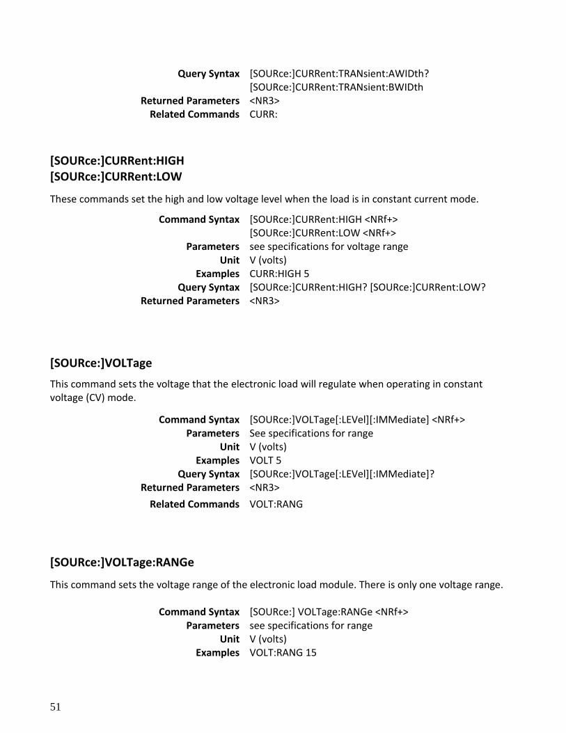
51
Query Syntax [SOURce:]CURRent:TRANsient:AWIDth? [SOURce:]CURRent:TRANsient:BWIDth
Returned Parameters <NR3> Related Commands CURR:
[SOURce:]CURRent:HIGH [SOURce:]CURRent:LOW
These commands set the high and low voltage level when the load is in constant current mode.
Command Syntax [SOURce:]CURRent:HIGH <NRf+> [SOURce:]CURRent:LOW <NRf+>
Parameters see specifications for voltage range Unit V (volts)
Examples CURR:HIGH 5 Query Syntax [SOURce:]CURRent:HIGH? [SOURce:]CURRent:LOW?
Returned Parameters <NR3>
[SOURce:]VOLTage
This command sets the voltage that the electronic load will regulate when operating in constant voltage (CV) mode.
Command Syntax [SOURce:]VOLTage[:LEVel][:IMMediate] <NRf+> Parameters See specifications for range
Unit V (volts) Examples VOLT 5
Query Syntax [SOURce:]VOLTage[:LEVel][:IMMediate]? Returned Parameters <NR3>
Related Commands VOLT:RANG
[SOURce:]VOLTage:RANGe
This command sets the voltage range of the electronic load module. There is only one voltage range.
Command Syntax [SOURce:] VOLTage:RANGe <NRf+> Parameters see specifications for range
Unit V (volts) Examples VOLT:RANG 15
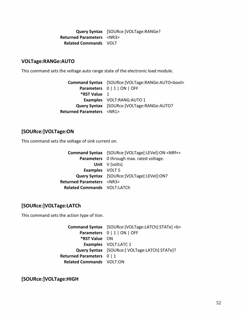
52
Query Syntax [SOURce:]VOLTage:RANGe? Returned Parameters <NR3>
Related Commands VOLT
VOLTage:RANGe:AUTO
This command sets the voltage auto range state of the electronic load module.
Command Syntax [SOURce:]VOLTage:RANGe:AUTO<bool> Parameters 0 | 1 | ON | OFF *RST Value 1
Examples VOLT:RANG:AUTO 1 Query Syntax [SOURce:]VOLTage:RANGe:AUTO?
Returned Parameters <NR1>
[SOURce:]VOLTage:ON
This command sets the voltage of sink current on.
Command Syntax [SOURce:]VOLTage[:LEVel]:ON <NRf+> Parameters 0 through max. rated voltage.
Unit V (volts) Examples VOLT 5
Query Syntax [SOURce:]VOLTage[:LEVel]:ON? Returned Parameters <NR3>
Related Commands VOLT:LATCh
[SOURce:]VOLTage:LATCh
This command sets the action type of Von.
Command Syntax [SOURce:]VOLTage:LATCh[:STATe] <b> Parameters 0 | 1 | ON | OFF *RST Value ON
Examples VOLT:LATC 1 Query Syntax [SOURce:] VOLTage:LATCh[:STATe]?
Returned Parameters 0 | 1 Related Commands VOLT:ON
[SOURce:]VOLTage:HIGH
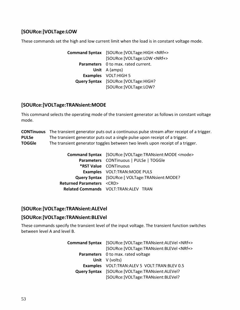
53
[SOURce:]VOLTage:LOW
These commands set the high and low current limit when the load is in constant voltage mode.
Command Syntax [SOURce:]VOLTage:HIGH <NRf+> [SOURce:]VOLTage:LOW <NRf+>
Parameters 0 to max. rated current. Unit A (amps)
Examples VOLT:HIGH 5 Query Syntax [SOURce:]VOLTage:HIGH?
[SOURce:]VOLTage:LOW?
[SOURce:]VOLTage:TRANsient:MODE
This command selects the operating mode of the transient generator as follows in constant voltage mode. CONTinuous The transient generator puts out a continuous pulse stream after receipt of a trigger. PULSe The transient generator puts out a single pulse upon receipt of a trigger. TOGGle The transient generator toggles between two levels upon receipt of a trigger.
Command Syntax [SOURce:]VOLTage:TRANsient:MODE <mode> Parameters CONTinuous | PULSe | TOGGle *RST Value CONTinuous
Examples VOLT:TRAN:MODE PULS Query Syntax [SOURce:] VOLTage:TRANsient:MODE?
Returned Parameters <CRD> Related Commands VOLT:TRAN:ALEV TRAN
[SOURce:]VOLTage:TRANsient:ALEVel
[SOURce:]VOLTage:TRANsient:BLEVel
These commands specify the transient level of the input voltage. The transient function switches between level A and level B.
Command Syntax [SOURce:]VOLTage:TRANsient:ALEVel <NRf+> [SOURce:]VOLTage:TRANsient:BLEVel <NRf+>
Parameters 0 to max. rated voltage Unit V (volts)
Examples VOLT:TRAN:ALEV 5 VOLT:TRAN:BLEV 0.5 Query Syntax [SOURce:]VOLTage:TRANsient:ALEVel?
[SOURce:]VOLTage:TRANsient:BLEVel?
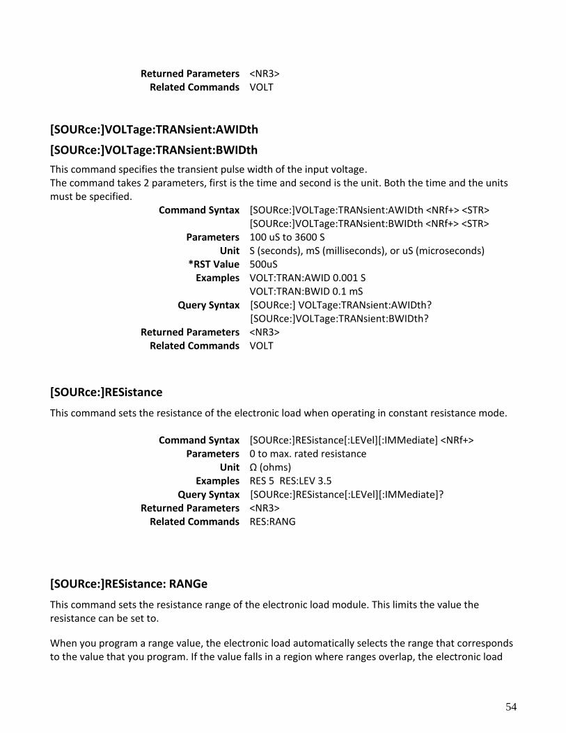
54
Returned Parameters <NR3> Related Commands VOLT
[SOURce:]VOLTage:TRANsient:AWIDth
[SOURce:]VOLTage:TRANsient:BWIDth
This command specifies the transient pulse width of the input voltage. The command takes 2 parameters, first is the time and second is the unit. Both the time and the units must be specified.
Command Syntax [SOURce:]VOLTage:TRANsient:AWIDth <NRf+> <STR> [SOURce:]VOLTage:TRANsient:BWIDth <NRf+> <STR>
Parameters 100 uS to 3600 S Unit S (seconds), mS (milliseconds), or uS (microseconds)
*RST Value 500uS Examples VOLT:TRAN:AWID 0.001 S
VOLT:TRAN:BWID 0.1 mS Query Syntax [SOURce:] VOLTage:TRANsient:AWIDth?
[SOURce:]VOLTage:TRANsient:BWIDth? Returned Parameters <NR3>
Related Commands VOLT
[SOURce:]RESistance
This command sets the resistance of the electronic load when operating in constant resistance mode.
Command Syntax [SOURce:]RESistance[:LEVel][:IMMediate] <NRf+> Parameters 0 to max. rated resistance
Unit Ω (ohms) Examples RES 5 RES:LEV 3.5
Query Syntax [SOURce:]RESistance[:LEVel][:IMMediate]? Returned Parameters <NR3>
Related Commands RES:RANG
[SOURce:]RESistance: RANGe
This command sets the resistance range of the electronic load module. This limits the value the resistance can be set to.
When you program a range value, the electronic load automatically selects the range that corresponds to the value that you program. If the value falls in a region where ranges overlap, the electronic load
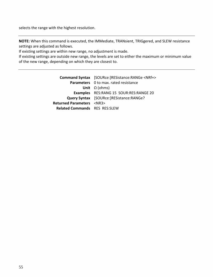
55
selects the range with the highest resolution.
NOTE: When this command is executed, the IMMediate, TRANsient, TRIGgered, and SLEW resistance settings are adjusted as follows. If existing settings are within new range, no adjustment is made. If existing settings are outside new range, the levels are set to either the maximum or minimum value of the new range, depending on which they are closest to.
Command Syntax [SOURce:]RESistance:RANGe <NRf+>
Parameters 0 to max. rated resistance Unit Ω (ohms)
Examples RES:RANG 15 SOUR:RES:RANGE 20 Query Syntax [SOURce:]RESistance:RANGe?
Returned Parameters <NR3> Related Commands RES RES:SLEW
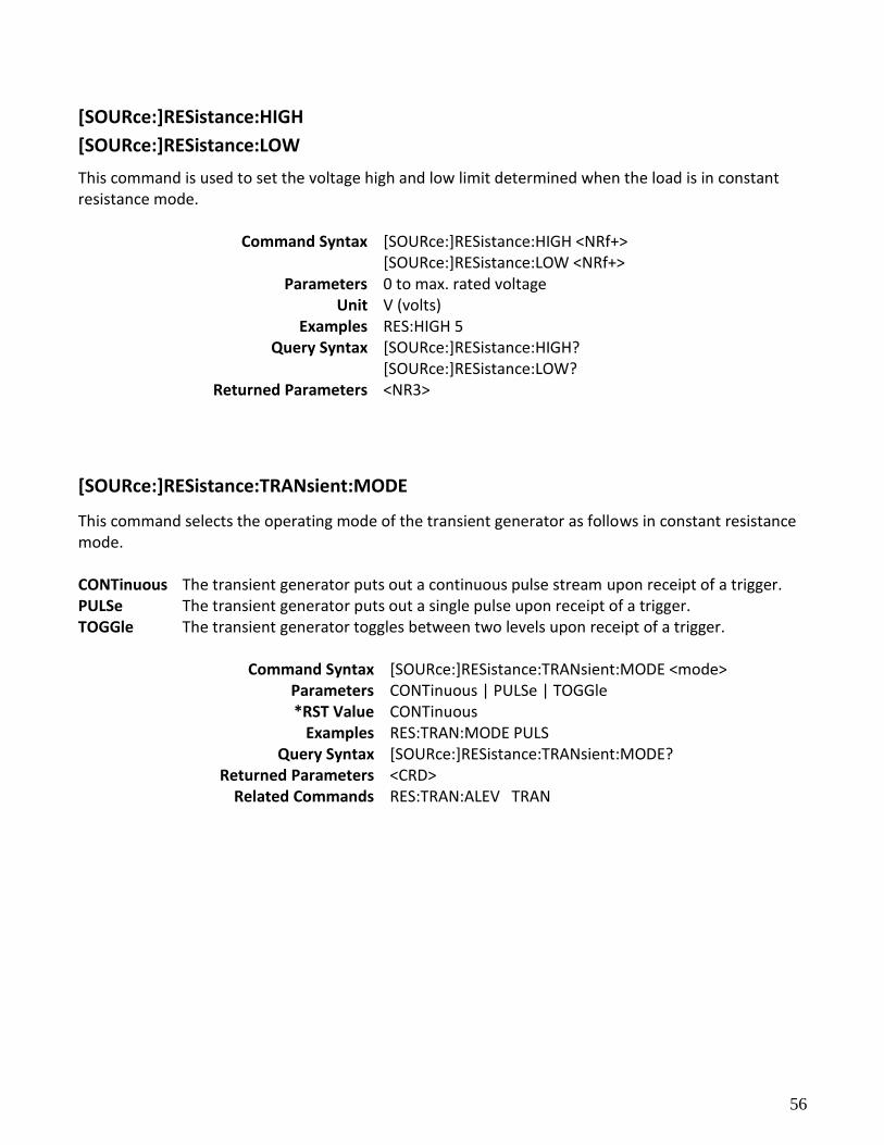
56
[SOURce:]RESistance:HIGH
[SOURce:]RESistance:LOW
This command is used to set the voltage high and low limit determined when the load is in constant resistance mode.
Command Syntax [SOURce:]RESistance:HIGH <NRf+> [SOURce:]RESistance:LOW <NRf+>
Parameters 0 to max. rated voltage Unit V (volts)
Examples RES:HIGH 5 Query Syntax [SOURce:]RESistance:HIGH?
[SOURce:]RESistance:LOW? Returned Parameters <NR3>
[SOURce:]RESistance:TRANsient:MODE
This command selects the operating mode of the transient generator as follows in constant resistance mode. CONTinuous The transient generator puts out a continuous pulse stream upon receipt of a trigger. PULSe The transient generator puts out a single pulse upon receipt of a trigger. TOGGle The transient generator toggles between two levels upon receipt of a trigger.
Command Syntax [SOURce:]RESistance:TRANsient:MODE <mode> Parameters CONTinuous | PULSe | TOGGle *RST Value CONTinuous
Examples RES:TRAN:MODE PULS Query Syntax [SOURce:]RESistance:TRANsient:MODE?
Returned Parameters <CRD> Related Commands RES:TRAN:ALEV TRAN
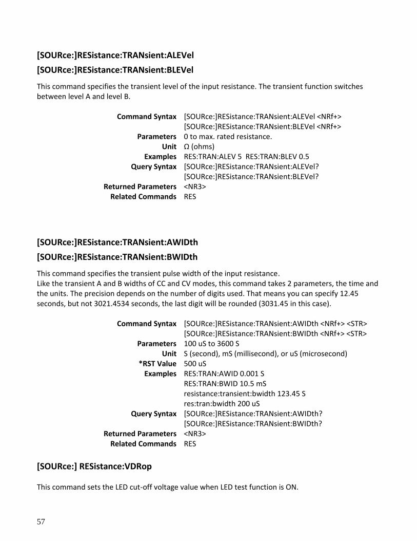
57
[SOURce:]RESistance:TRANsient:ALEVel
[SOURce:]RESistance:TRANsient:BLEVel
This command specifies the transient level of the input resistance. The transient function switches between level A and level B.
Command Syntax [SOURce:]RESistance:TRANsient:ALEVel <NRf+> [SOURce:]RESistance:TRANsient:BLEVel <NRf+>
Parameters 0 to max. rated resistance. Unit Ω (ohms)
Examples RES:TRAN:ALEV 5 RES:TRAN:BLEV 0.5 Query Syntax [SOURce:]RESistance:TRANsient:ALEVel?
[SOURce:]RESistance:TRANsient:BLEVel? Returned Parameters <NR3>
Related Commands RES
[SOURce:]RESistance:TRANsient:AWIDth
[SOURce:]RESistance:TRANsient:BWIDth
This command specifies the transient pulse width of the input resistance. Like the transient A and B widths of CC and CV modes, this command takes 2 parameters, the time and the units. The precision depends on the number of digits used. That means you can specify 12.45 seconds, but not 3021.4534 seconds, the last digit will be rounded (3031.45 in this case).
Command Syntax [SOURce:]RESistance:TRANsient:AWIDth <NRf+> <STR> [SOURce:]RESistance:TRANsient:BWIDth <NRf+> <STR>
Parameters 100 uS to 3600 S Unit S (second), mS (millisecond), or uS (microsecond)
*RST Value 500 uS Examples RES:TRAN:AWID 0.001 S
RES:TRAN:BWID 10.5 mS resistance:transient:bwidth 123.45 S res:tran:bwidth 200 uS
Query Syntax [SOURce:]RESistance:TRANsient:AWIDth? [SOURce:]RESistance:TRANsient:BWIDth?
Returned Parameters <NR3> Related Commands RES
[SOURce:] RESistance:VDRop This command sets the LED cut-off voltage value when LED test function is ON.
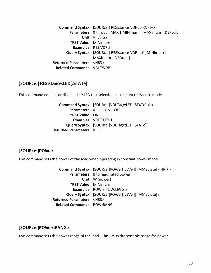
58
Command Syntax [SOURce:] RESistance:VDRop <NRf+> Parameters 0 through MAX | MINimum | MAXimum | DEFault
Unit V (volts) *RST Value MINimum
Examples RES:VDR 5 Query Syntax [SOURce:] RESistance:VDRop? [ MINimum |
MAXimum | DEFault ] Returned Parameters <NR3>
Related Commands VOLT:VDR
[SOURce:] RESistance:LED[:STATe] This command enables or disables the LED test selection in constant resistence mode.
Command Syntax [SOURce:]VOLTage:LED[:STATe] <b> Parameters 0 | 1 | ON | OFF *RST Value ON
Examples VOLT:LED 1 Query Syntax [SOURce:]VOLTage:LED[:STATe]?
Returned Parameters 0 | 1
[SOURce:]POWer
This command sets the power of the load when operating in constant power mode.
Command Syntax [SOURce:]POWer[:LEVel][:IMMediate] <NRf+> Parameters 0 to max. rated power
Unit W (power) *RST Value MINimum
Examples POW 5 POW:LEV 3.5 Query Syntax [SOURce:]POWer[:LEVel][:IMMediate]?
Returned Parameters <NR3> Related Commands POW:RANG
[SOURce:]POWer:RANGe
This command sets the power range of the load. This limits the settable range for power.
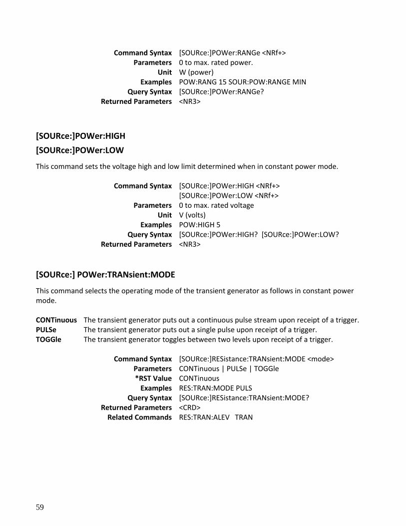
59
Command Syntax [SOURce:]POWer:RANGe <NRf+> Parameters 0 to max. rated power.
Unit W (power) Examples POW:RANG 15 SOUR:POW:RANGE MIN
Query Syntax [SOURce:]POWer:RANGe? Returned Parameters <NR3>
[SOURce:]POWer:HIGH
[SOURce:]POWer:LOW
This command sets the voltage high and low limit determined when in constant power mode.
Command Syntax [SOURce:]POWer:HIGH <NRf+> [SOURce:]POWer:LOW <NRf+>
Parameters 0 to max. rated voltage Unit V (volts)
Examples POW:HIGH 5 Query Syntax [SOURce:]POWer:HIGH? [SOURce:]POWer:LOW?
Returned Parameters <NR3>
[SOURce:] POWer:TRANsient:MODE
This command selects the operating mode of the transient generator as follows in constant power mode. CONTinuous The transient generator puts out a continuous pulse stream upon receipt of a trigger. PULSe The transient generator puts out a single pulse upon receipt of a trigger. TOGGle The transient generator toggles between two levels upon receipt of a trigger.
Command Syntax [SOURce:]RESistance:TRANsient:MODE <mode> Parameters CONTinuous | PULSe | TOGGle *RST Value CONTinuous
Examples RES:TRAN:MODE PULS Query Syntax [SOURce:]RESistance:TRANsient:MODE?
Returned Parameters <CRD> Related Commands RES:TRAN:ALEV TRAN
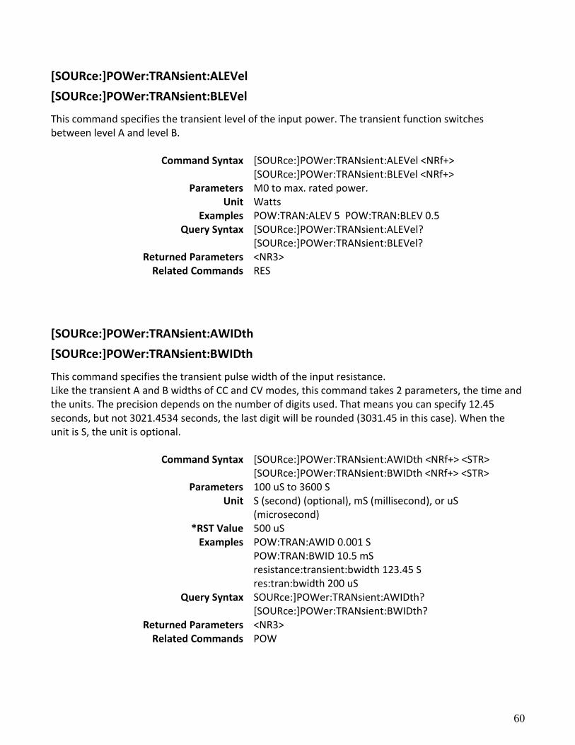
60
[SOURce:]POWer:TRANsient:ALEVel
[SOURce:]POWer:TRANsient:BLEVel
This command specifies the transient level of the input power. The transient function switches between level A and level B.
Command Syntax [SOURce:]POWer:TRANsient:ALEVel <NRf+> [SOURce:]POWer:TRANsient:BLEVel <NRf+>
Parameters M0 to max. rated power. Unit Watts
Examples POW:TRAN:ALEV 5 POW:TRAN:BLEV 0.5 Query Syntax [SOURce:]POWer:TRANsient:ALEVel?
[SOURce:]POWer:TRANsient:BLEVel? Returned Parameters <NR3>
Related Commands RES
[SOURce:]POWer:TRANsient:AWIDth
[SOURce:]POWer:TRANsient:BWIDth
This command specifies the transient pulse width of the input resistance. Like the transient A and B widths of CC and CV modes, this command takes 2 parameters, the time and the units. The precision depends on the number of digits used. That means you can specify 12.45 seconds, but not 3021.4534 seconds, the last digit will be rounded (3031.45 in this case). When the unit is S, the unit is optional.
Command Syntax [SOURce:]POWer:TRANsient:AWIDth <NRf+> <STR> [SOURce:]POWer:TRANsient:BWIDth <NRf+> <STR>
Parameters 100 uS to 3600 S Unit S (second) (optional), mS (millisecond), or uS
(microsecond) *RST Value 500 uS
Examples POW:TRAN:AWID 0.001 S POW:TRAN:BWID 10.5 mS resistance:transient:bwidth 123.45 S res:tran:bwidth 200 uS
Query Syntax SOURce:]POWer:TRANsient:AWIDth? [SOURce:]POWer:TRANsient:BWIDth?
Returned Parameters <NR3> Related Commands POW
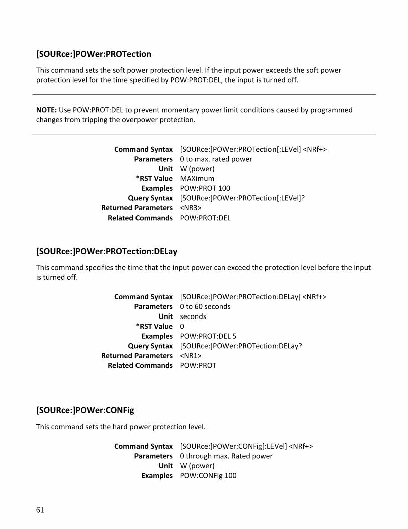
61
[SOURce:]POWer:PROTection
This command sets the soft power protection level. If the input power exceeds the soft power protection level for the time specified by POW:PROT:DEL, the input is turned off.
NOTE: Use POW:PROT:DEL to prevent momentary power limit conditions caused by programmed changes from tripping the overpower protection.
Command Syntax [SOURce:]POWer:PROTection[:LEVel] <NRf+>
Parameters 0 to max. rated power Unit W (power)
*RST Value MAXimum Examples POW:PROT 100
Query Syntax [SOURce:]POWer:PROTection[:LEVel]? Returned Parameters <NR3>
Related Commands POW:PROT:DEL
[SOURce:]POWer:PROTection:DELay
This command specifies the time that the input power can exceed the protection level before the input is turned off.
Command Syntax [SOURce:]POWer:PROTection:DELay] <NRf+> Parameters 0 to 60 seconds
Unit seconds *RST Value 0
Examples POW:PROT:DEL 5 Query Syntax [SOURce:]POWer:PROTection:DELay?
Returned Parameters <NR1> Related Commands POW:PROT
[SOURce:]POWer:CONFig
This command sets the hard power protection level.
Command Syntax [SOURce:]POWer:CONFig[:LEVel] <NRf+> Parameters 0 through max. Rated power
Unit W (power) Examples POW:CONFig 100
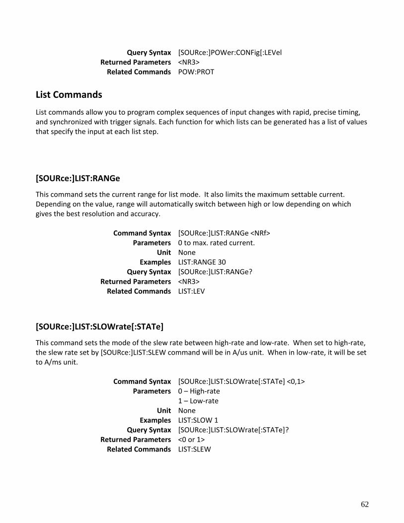
62
Query Syntax [SOURce:]POWer:CONFig[:LEVel Returned Parameters <NR3>
Related Commands POW:PROT
List Commands
List commands allow you to program complex sequences of input changes with rapid, precise timing, and synchronized with trigger signals. Each function for which lists can be generated has a list of values that specify the input at each list step.
[SOURce:]LIST:RANGe
This command sets the current range for list mode. It also limits the maximum settable current. Depending on the value, range will automatically switch between high or low depending on which gives the best resolution and accuracy.
Command Syntax [SOURce:]LIST:RANGe <NRf> Parameters 0 to max. rated current.
Unit None Examples LIST:RANGE 30
Query Syntax [SOURce:]LIST:RANGe? Returned Parameters <NR3>
Related Commands LIST:LEV
[SOURce:]LIST:SLOWrate[:STATe]
This command sets the mode of the slew rate between high-rate and low-rate. When set to high-rate, the slew rate set by [SOURce:]LIST:SLEW command will be in A/us unit. When in low-rate, it will be set to A/ms unit.
Command Syntax [SOURce:]LIST:SLOWrate[:STATe] <0,1> Parameters 0 – High-rate
1 – Low-rate Unit None
Examples LIST:SLOW 1 Query Syntax [SOURce:]LIST:SLOWrate[:STATe]?
Returned Parameters <0 or 1> Related Commands LIST:SLEW
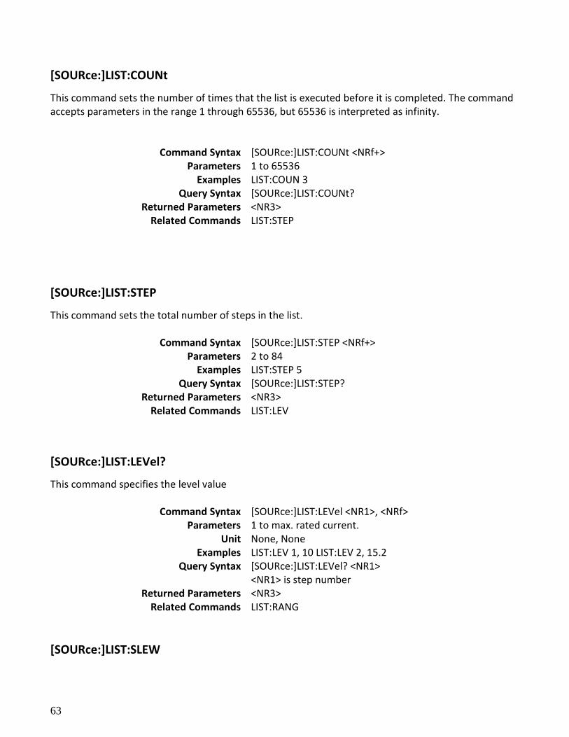
63
[SOURce:]LIST:COUNt
This command sets the number of times that the list is executed before it is completed. The command accepts parameters in the range 1 through 65536, but 65536 is interpreted as infinity.
Command Syntax [SOURce:]LIST:COUNt <NRf+> Parameters 1 to 65536
Examples LIST:COUN 3 Query Syntax [SOURce:]LIST:COUNt?
Returned Parameters <NR3> Related Commands LIST:STEP
[SOURce:]LIST:STEP
This command sets the total number of steps in the list.
Command Syntax [SOURce:]LIST:STEP <NRf+> Parameters 2 to 84
Examples LIST:STEP 5 Query Syntax [SOURce:]LIST:STEP?
Returned Parameters <NR3> Related Commands LIST:LEV
[SOURce:]LIST:LEVel?
This command specifies the level value
Command Syntax [SOURce:]LIST:LEVel <NR1>, <NRf> Parameters 1 to max. rated current.
Unit None, None Examples LIST:LEV 1, 10 LIST:LEV 2, 15.2
Query Syntax [SOURce:]LIST:LEVel? <NR1> <NR1> is step number
Returned Parameters <NR3> Related Commands LIST:RANG
[SOURce:]LIST:SLEW
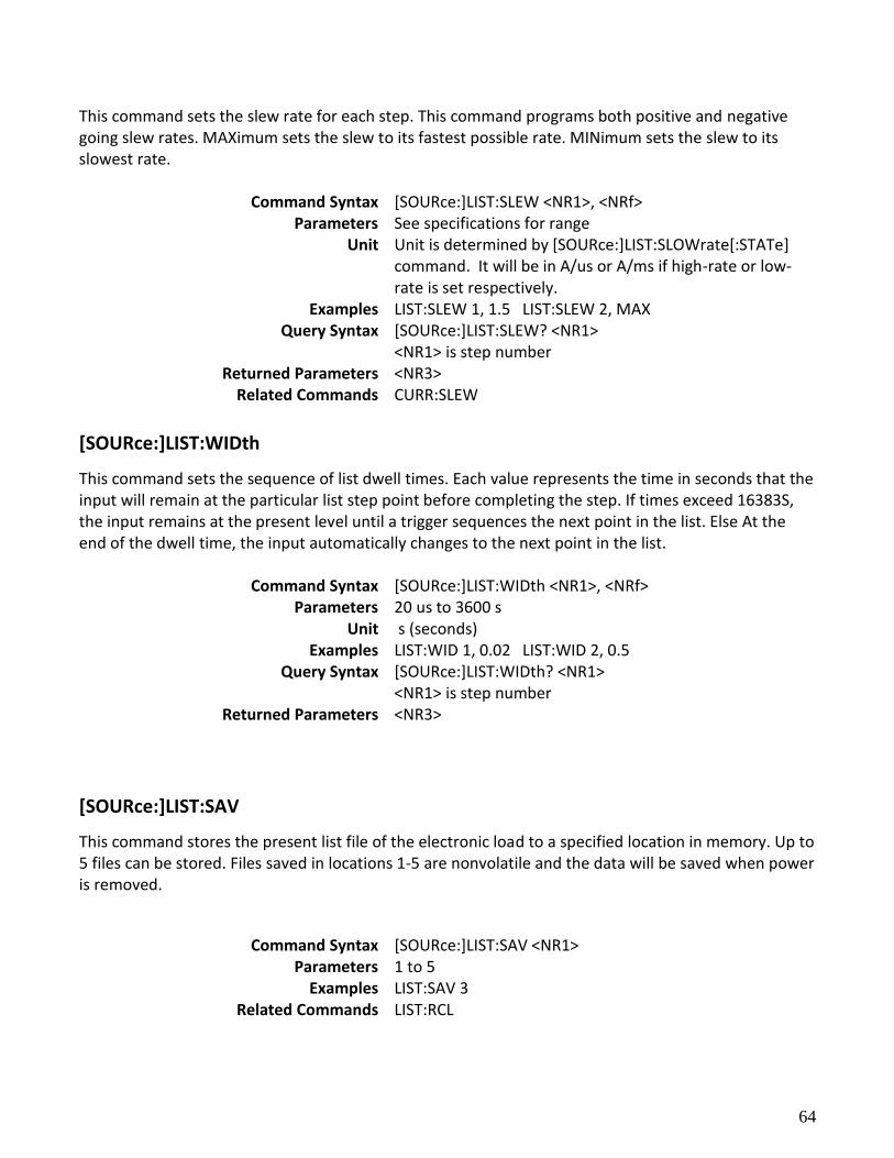
64
This command sets the slew rate for each step. This command programs both positive and negative going slew rates. MAXimum sets the slew to its fastest possible rate. MINimum sets the slew to its slowest rate.
Command Syntax [SOURce:]LIST:SLEW <NR1>, <NRf> Parameters See specifications for range
Unit Unit is determined by [SOURce:]LIST:SLOWrate[:STATe] command. It will be in A/us or A/ms if high-rate or low-rate is set respectively.
Examples LIST:SLEW 1, 1.5 LIST:SLEW 2, MAX Query Syntax [SOURce:]LIST:SLEW? <NR1>
<NR1> is step number Returned Parameters <NR3>
Related Commands CURR:SLEW
[SOURce:]LIST:WIDth
This command sets the sequence of list dwell times. Each value represents the time in seconds that the input will remain at the particular list step point before completing the step. If times exceed 16383S, the input remains at the present level until a trigger sequences the next point in the list. Else At the end of the dwell time, the input automatically changes to the next point in the list.
Command Syntax [SOURce:]LIST:WIDth <NR1>, <NRf> Parameters 20 us to 3600 s
Unit s (seconds) Examples LIST:WID 1, 0.02 LIST:WID 2, 0.5
Query Syntax [SOURce:]LIST:WIDth? <NR1> <NR1> is step number
Returned Parameters <NR3>
[SOURce:]LIST:SAV
This command stores the present list file of the electronic load to a specified location in memory. Up to 5 files can be stored. Files saved in locations 1-5 are nonvolatile and the data will be saved when power is removed.
Command Syntax [SOURce:]LIST:SAV <NR1> Parameters 1 to 5
Examples LIST:SAV 3 Related Commands LIST:RCL
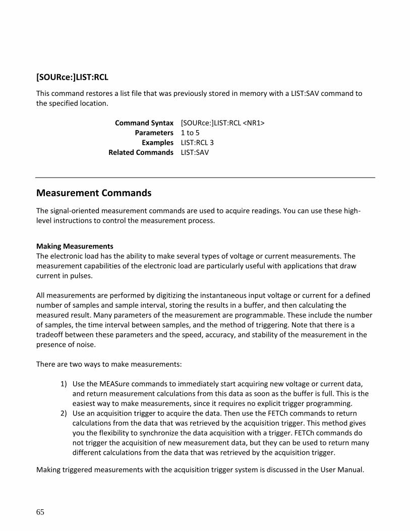
65
[SOURce:]LIST:RCL
This command restores a list file that was previously stored in memory with a LIST:SAV command to the specified location.
Command Syntax [SOURce:]LIST:RCL <NR1> Parameters 1 to 5
Examples LIST:RCL 3 Related Commands LIST:SAV
Measurement Commands
The signal-oriented measurement commands are used to acquire readings. You can use these high-level instructions to control the measurement process.
Making Measurements The electronic load has the ability to make several types of voltage or current measurements. The measurement capabilities of the electronic load are particularly useful with applications that draw current in pulses. All measurements are performed by digitizing the instantaneous input voltage or current for a defined number of samples and sample interval, storing the results in a buffer, and then calculating the measured result. Many parameters of the measurement are programmable. These include the number of samples, the time interval between samples, and the method of triggering. Note that there is a tradeoff between these parameters and the speed, accuracy, and stability of the measurement in the presence of noise. There are two ways to make measurements:
1) Use the MEASure commands to immediately start acquiring new voltage or current data, and return measurement calculations from this data as soon as the buffer is full. This is the easiest way to make measurements, since it requires no explicit trigger programming.
2) Use an acquisition trigger to acquire the data. Then use the FETCh commands to return calculations from the data that was retrieved by the acquisition trigger. This method gives you the flexibility to synchronize the data acquisition with a trigger. FETCh commands do not trigger the acquisition of new measurement data, but they can be used to return many different calculations from the data that was retrieved by the acquisition trigger.
Making triggered measurements with the acquisition trigger system is discussed in the User Manual.
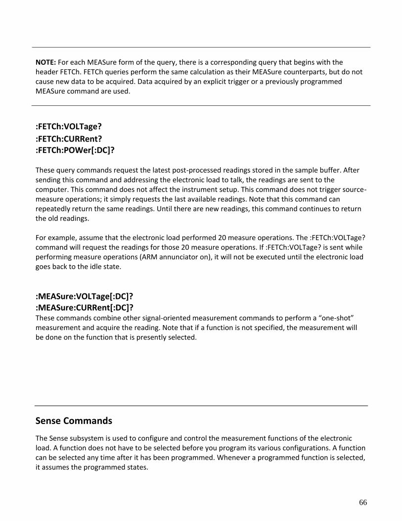
66
NOTE: For each MEASure form of the query, there is a corresponding query that begins with the header FETCh. FETCh queries perform the same calculation as their MEASure counterparts, but do not cause new data to be acquired. Data acquired by an explicit trigger or a previously programmed MEASure command are used.
:FETCh:VOLTage?
:FETCh:CURRent? :FETCh:POWer[:DC]? These query commands request the latest post-processed readings stored in the sample buffer. After sending this command and addressing the electronic load to talk, the readings are sent to the computer. This command does not affect the instrument setup. This command does not trigger source-measure operations; it simply requests the last available readings. Note that this command can repeatedly return the same readings. Until there are new readings, this command continues to return the old readings. For example, assume that the electronic load performed 20 measure operations. The :FETCh:VOLTage? command will request the readings for those 20 measure operations. If :FETCh:VOLTage? is sent while performing measure operations (ARM annunciator on), it will not be executed until the electronic load goes back to the idle state.
:MEASure:VOLTage[:DC]? :MEASure:CURRent[:DC]? These commands combine other signal-oriented measurement commands to perform a “one-shot” measurement and acquire the reading. Note that if a function is not specified, the measurement will be done on the function that is presently selected.
Sense Commands
The Sense subsystem is used to configure and control the measurement functions of the electronic load. A function does not have to be selected before you program its various configurations. A function can be selected any time after it has been programmed. Whenever a programmed function is selected, it assumes the programmed states.
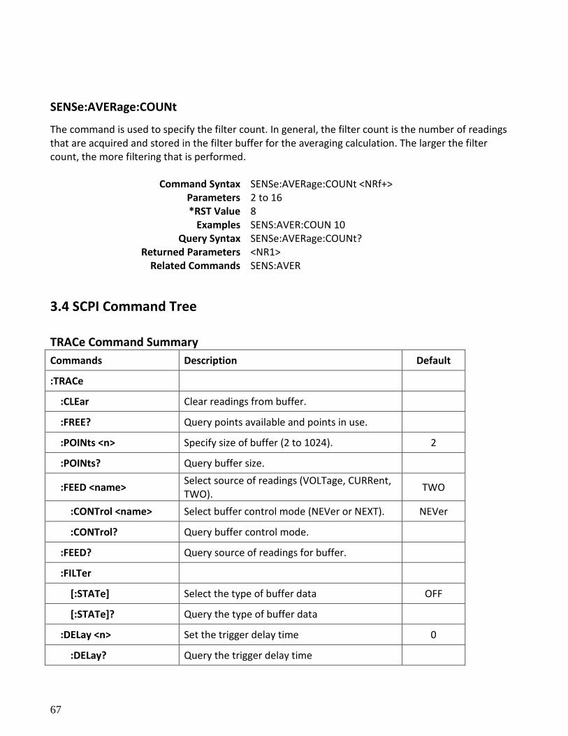
67
SENSe:AVERage:COUNt
The command is used to specify the filter count. In general, the filter count is the number of readings that are acquired and stored in the filter buffer for the averaging calculation. The larger the filter count, the more filtering that is performed.
Command Syntax SENSe:AVERage:COUNt <NRf+> Parameters 2 to 16 *RST Value 8
Examples SENS:AVER:COUN 10 Query Syntax SENSe:AVERage:COUNt?
Returned Parameters <NR1> Related Commands SENS:AVER
3.4 SCPI Command Tree
TRACe Command Summary
Commands Description Default
:TRACe
:CLEar Clear readings from buffer.
:FREE? Query points available and points in use.
:POINts <n> Specify size of buffer (2 to 1024). 2
:POINts? Query buffer size.
:FEED <name> Select source of readings (VOLTage, CURRent, TWO).
TWO
:CONTrol <name> Select buffer control mode (NEVer or NEXT). NEVer
:CONTrol? Query buffer control mode.
:FEED? Query source of readings for buffer.
:FILTer
[:STATe] Select the type of buffer data OFF
[:STATe]? Query the type of buffer data
:DELay <n> Set the trigger delay time 0
:DELay? Query the trigger delay time

68
:TIMer <n> Set the timer interval 1
:TIMer? Query the timer interval
:DATA? Read all data in the buffer.
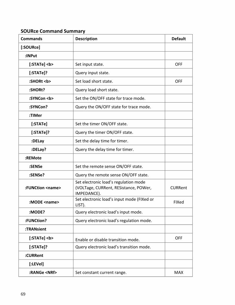
69
SOURce Command Summary
Commands Description Default
[:SOURce]
:INPut
[:STATe] <b> Set input state. OFF
[:STATe]? Query input state.
:SHORt <b> Set load short state. OFF
:SHORt? Query load short state.
:SYNCon <b> Set the ON/OFF state for trace mode.
:SYNCon? Query the ON/OFF state for trace mode.
:TIMer
[:STATe] Set the timer ON/OFF state.
[:STATe]? Query the timer ON/OFF state.
:DELay Set the delay time for timer.
:DELay? Query the delay time for timer.
:REMote
:SENSe Set the remote sense ON/OFF state.
:SENSe? Query the remote sense ON/OFF state.
:FUNCtion <name> Set electronic load’s regulation mode (VOLTage, CURRent, RESistance, POWer, IMPEDANCE).
CURRent
:MODE <name> Set electronic load’s input mode (FIXed or LIST).
FIXed
:MODE? Query electronic load’s input mode.
:FUNCtion? Query electronic load’s regulation mode.
:TRANsient
[:STATe] <b> Enable or disable transition mode. OFF
[:STATe]? Query electronic load’s transition mode.
:CURRent
[:LEVel]
:RANGe <NRf> Set constant current range. MAX
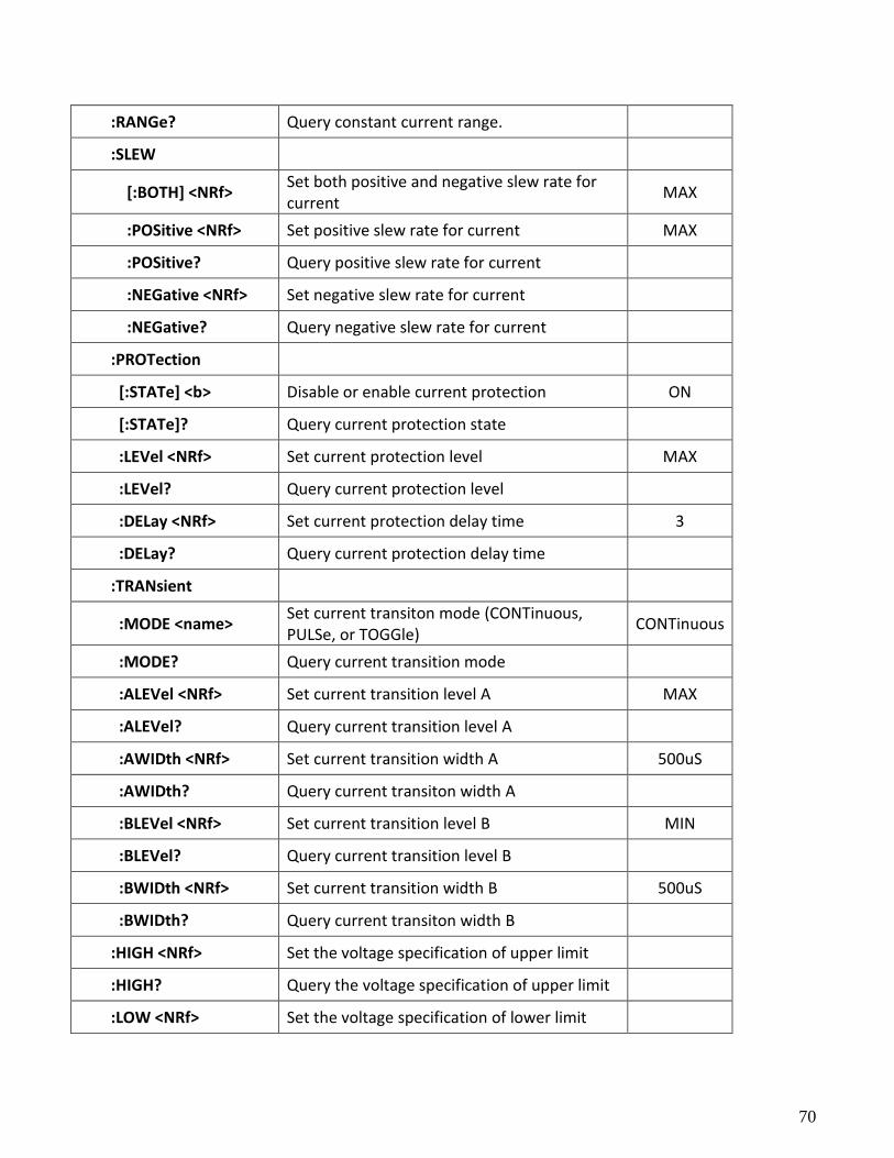
70
:RANGe? Query constant current range.
:SLEW
[:BOTH] <NRf> Set both positive and negative slew rate for current
MAX
:POSitive <NRf> Set positive slew rate for current MAX
:POSitive? Query positive slew rate for current
:NEGative <NRf> Set negative slew rate for current
:NEGative? Query negative slew rate for current
:PROTection
[:STATe] <b> Disable or enable current protection ON
[:STATe]? Query current protection state
:LEVel <NRf> Set current protection level MAX
:LEVel? Query current protection level
:DELay <NRf> Set current protection delay time 3
:DELay? Query current protection delay time
:TRANsient
:MODE <name> Set current transiton mode (CONTinuous, PULSe, or TOGGle)
CONTinuous
:MODE? Query current transition mode
:ALEVel <NRf> Set current transition level A MAX
:ALEVel? Query current transition level A
:AWIDth <NRf> Set current transition width A 500uS
:AWIDth? Query current transiton width A
:BLEVel <NRf> Set current transition level B MIN
:BLEVel? Query current transition level B
:BWIDth <NRf> Set current transition width B 500uS
:BWIDth? Query current transiton width B
:HIGH <NRf> Set the voltage specification of upper limit
:HIGH? Query the voltage specification of upper limit
:LOW <NRf> Set the voltage specification of lower limit
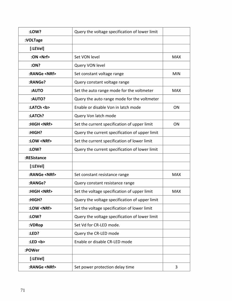
71
:LOW? Query the voltage specification of lower limit
:VOLTage
[:LEVel]
:ON <Nrf> Set VON level MAX
:ON? Query VON level
:RANGe <NRf> Set constant voltage range MIN
:RANGe? Query constant voltage range
:AUTO Set the auto range mode for the voltmeter MAX
:AUTO? Query the auto range mode for the voltmeter
:LATCh <b> Enable or disable Von in latch mode ON
:LATCh? Query Von latch mode
:HIGH <NRf> Set the current specification of upper limit ON
:HIGH? Query the current specification of upper limit
:LOW <NRf> Set the current specification of lower limit
:LOW? Query the current specification of lower limit
:RESistance
[:LEVel]
:RANGe <NRf> Set constant resistance range MAX
:RANGe? Query constant resistance range
:HIGH <NRf> Set the voltage specification of upper limit MAX
:HIGH? Query the voltage specification of upper limit
:LOW <NRf> Set the voltage specification of lower limit
:LOW? Query the voltage specification of lower limit
:VDRop Set Vd for CR-LED mode.
:LED? Query the CR-LED mode
:LED <b> Enable or disable CR-LED mode
:POWer
[:LEVel]
:RANGe <NRf> Set power protection delay time 3
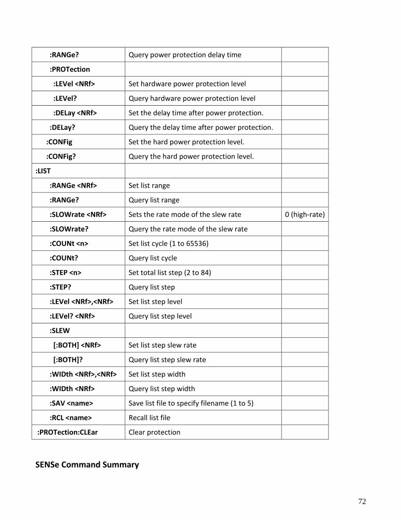
72
:RANGe? Query power protection delay time
:PROTection
:LEVel <NRf> Set hardware power protection level
:LEVel? Query hardware power protection level
:DELay <NRf> Set the delay time after power protection.
:DELay? Query the delay time after power protection.
:CONFig Set the hard power protection level.
:CONFig? Query the hard power protection level.
:LIST
:RANGe <NRf> Set list range
:RANGe? Query list range
:SLOWrate <NRf> Sets the rate mode of the slew rate 0 (high-rate)
:SLOWrate? Query the rate mode of the slew rate
:COUNt <n> Set list cycle (1 to 65536)
:COUNt? Query list cycle
:STEP <n> Set total list step (2 to 84)
:STEP? Query list step
:LEVel <NRf>,<NRf> Set list step level
:LEVel? <NRf> Query list step level
:SLEW
[:BOTH] <NRf> Set list step slew rate
[:BOTH]? Query list step slew rate
:WIDth <NRf>,<NRf> Set list step width
:WIDth <NRf> Query list step width
:SAV <name> Save list file to specify filename (1 to 5)
:RCL <name> Recall list file
:PROTection:CLEar Clear protection
SENSe Command Summary
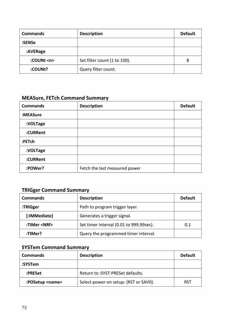
73
Commands Description Default
:SENSe
:AVERage
:COUNt <n> Set filter count (1 to 100). 8
:COUNt? Query filter count.
MEASure, FETch Command Summary
Commands Description Default
:MEASure
:VOLTage
:CURRent
:FETch
:VOLTage
:CURRent
:POWer? Fetch the last measured power
TRIGger Command Summary
Commands Description Default
:TRIGger Path to program trigger layer.
[:IMMediate] Generates a trigger signal.
:TIMer <NRf> Set timer interval (0.01 to 999.99sec). 0.1
:TIMer? Query the programmed timer interval.
SYSTem Command Summary
Commands Description Default
:SYSTem
:PRESet Return to :SYST:PRESet defaults.
:POSetup <name> Select power-on setup: (RST or SAV0). RST
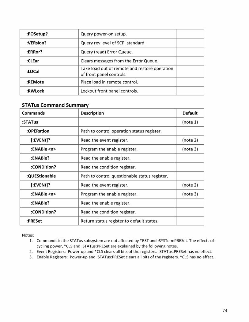
74
:POSetup? Query power-on setup.
:VERsion? Query rev level of SCPI standard.
:ERRor? Query (read) Error Queue.
:CLEar Clears messages from the Error Queue.
:LOCal Take load out of remote and restore operation of front panel controls.
:REMote Place load in remote control.
:RWLock Lockout front panel controls.
STATus Command Summary
Commands Description Default
:STATus (note 1)
:OPERation Path to control operation status register.
[:EVENt]? Read the event register. (note 2)
:ENABle <n> Program the enable register. (note 3)
:ENABle? Read the enable register.
:CONDition? Read the condition register.
:QUEStionable Path to control questionable status register.
[:EVENt]? Read the event register. (note 2)
:ENABle <n> Program the enable register. (note 3)
:ENABle? Read the enable register.
:CONDition? Read the condition register.
:PRESet Return status register to default states.
Notes:
1. Commands in the STATus subsystem are not affected by *RST and :SYSTem:PRESet. The effects of cycling power, *CLS and :STATus:PRESet are explained by the following notes.
2. Event Registers: Power-up and *CLS clears all bits of the registers. :STATus:PRESet has no effect. 3. Enable Registers: Power-up and :STATus:PRESet clears all bits of the registers. *CLS has no effect.
75
Chapter 4
Programming Examples
4.1 Introduction This chapter contains examples on how to program your electronic load. Simple examples show you how to program:
Input functions such as voltage, current, and resistance
Measurement functions
Status and protection functions
Transient functions, including lists
NOTE: The examples in this chapter show which commands are used to perform a particular function, but do not show the commands being used in any particular programming environment.
4.2 Programming the Input Power-on Initialization When the electronic load is first turned on, it wakes up with the input state set OFF. The following commands are given implicitly at power-on:
*RST or *RCL 0
*CLS
*SRE 0
*ESE 0 *RST is a convenient way to program all parameters to a known state. Refer to the *RST command in 3.2 Common Commands to see how each programmable parameter is set by *RST. Refer to the *PSC command in 3.2 Common Commands for more information on the power-on initialization of the *ESE and the *SRE registers.
Enabling the Input
76
To enable the input, use the command:
INPut ON
Input Voltage
The input voltage is controlled with the VOLTage command. For example, to set the input voltage to 25 volts, use:
VOLTage 25
Input Current
All models have a programmable current function. The command to program the current is:
CURRent <n>
where <n> is the input current in amps.
Overcurrent Protection
The electronic load can also be programmed to turn off its input if the current protection level is reached.
As explained in 3.3 Subsystem Commands, this protection feature is implemented by the following command:
CURRent:PROTection:STATe ON | OFF
NOTE: Use CURRent:PROTection:DELay to prevent momentary current limit conditions caused by programmed input changes from tripping the overcurrent protection.
Generating Triggers
You can generate a single trigger by sending the following command over the GPIB:
TRIGger:IMMediate
Note that this command will always generate a trigger. Use the TRIGger:SOURce command to select other trigger sources such as the mainframe's external trigger input.
Programming Transients
Transient operation is used to synchronize input changes with internal or external trigger signals, and
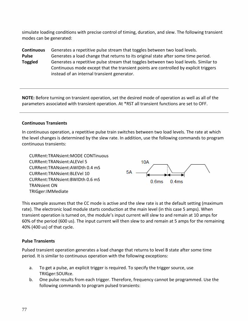
77
simulate loading conditions with precise control of timing, duration, and slew. The following transient modes can be generated: Continuous Generates a repetitive pulse stream that toggles between two load levels. Pulse Generates a load change that returns to its original state after some time period. Toggled Generates a repetitive pulse stream that toggles between two load levels. Similar to
Continuous mode except that the transient points are controlled by explicit triggers instead of an internal transient generator.
NOTE: Before turning on transient operation, set the desired mode of operation as well as all of the parameters associated with transient operation. At *RST all transient functions are set to OFF.
Continuous Transients
In continuous operation, a repetitive pulse train switches between two load levels. The rate at which the level changes is determined by the slew rate. In addition, use the following commands to program continuous transients:
CURRent:TRANsient:MODE CONTinuous CURRent:TRANsient:ALEVel 5 CURRent:TRANsient:AWIDth 0.4 mS CURRent:TRANsient:BLEVel 10 CURRent:TRANsient:BWIDth 0.6 mS TRANsient ON TRIGger:IMMediate
This example assumes that the CC mode is active and the slew rate is at the default setting (maximum rate). The electronic load module starts conduction at the main level (in this case 5 amps). When transient operation is turned on, the module’s input current will slew to and remain at 10 amps for 60% of the period (600 us). The input current will then slew to and remain at 5 amps for the remaining 40% (400 us) of that cycle.
Pulse Transients
Pulsed transient operation generates a load change that returns to level B state after some time period. It is similar to continuous operation with the following exceptions:
a. To get a pulse, an explicit trigger is required. To specify the trigger source, use TRIGger:SOURce.
b. One pulse results from each trigger. Therefore, frequency cannot be programmed. Use the following commands to program pulsed transients:
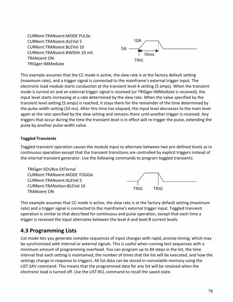
78
CURRent:TRANsient:MODE PULSe CURRent:TRANsient:ALEVel 5 CURRent:TRANsient:BLEVel 10 CURRent:TRANsient:BWIDth 10 mS TRANsient ON TRIGger:IMMediate
This example assumes that the CC mode is active, the slew rate is at the factory default setting (maximum rate), and a trigger signal is connected to the mainframe's external trigger input. The electronic load module starts conduction at the transient level A setting (5 amps). When the transient mode is turned on and an external trigger signal is received (or TRIGger:IMMediate is received), the input level starts increasing at a rate determined by the slew rate. When the value specified by the transient level setting (5 amps) is reached, it stays there for the remainder of the time determined by the pulse width setting (10 ms). After this time has elapsed, the input level decreases to the main level again at the rate specified by the slew setting and remains there until another trigger is received. Any triggers that occur during the time the transient level is in effect will re-trigger the pulse, extending the pulse by another pulse-width value.
Toggled Transients
Toggled transient operation causes the module input to alternate between two pre-defined levels as in continuous operation except that the transient transitions are controlled by explicit triggers instead of the internal transient generator. Use the following commands to program toggled transients:
TRIGger:SOURce EXTernal CURRent:TRANsient:MODE TOGGle CURRent:TRANsient:ALEVel 5 CURRent:TRANsition:BLEVel 10 TRANsient ON
This example assumes that CC mode is active, the slew rate is at the factory default setting (maximum rate) and a trigger signal is connected to the mainframe's external trigger input. Toggled transient operation is similar to that described for continuous and pulse operation, except that each time a trigger is received the input alternates between the level A and level B current levels.
4.3 Programming Lists List mode lets you generate complex sequences of input changes with rapid, precise timing, which may be synchronized with internal or external signals. This is useful when running test sequences with a minimum amount of programming overhead. You can program up to 84 steps in the list, the time interval that each setting is maintained, the number of times that the list will be executed, and how the settings change in response to triggers. All list data can be stored in nonvolatile memory using the LIST:SAV command. This means that the programmed data for any list will be retained when the electronic load is turned off. Use the LIST:RCL command to recall the saved state.
79
4-Step Current Change List Example The following example procedure shows how to generate and save a simple 4-step list of current changes. When programming, be sure to verify all parameters are within the module’s specifications.
1. Set the current range of the list. LIST:RANGe 40
2. Set the list cycle. LIST:COUNt 10000
3. Specify the number of steps in the list. LIST:STEP 4
4. Specify the current setting for step 1. LIST:LEVel 1,5
5. Set the current slew rate for step 1. LIST:SLEW 1,1
6. Set the width for step 1. LIST:WIDth 1,10ms
7. Specify the current setting for step 2. LIST:LEVel 2,10
8. Set the current slew rate for step 2. LIST:SLEW 2,1
9. Set the width for step 2. LIST:WIDth 2,10ms
10. Specify the current setting for step 3. LIST:LEVel 3,20
11. Set the current slew rate for step 3.
LIST:SLEW 3,1
12. Set the width for step 3. LIST:WIDth 3,10ms
13. Specify the current setting for step 4. LIST:LEVel 4,15
14. Set the current slew rate for step 4. LIST:SLEW 4,1
15. Set the width for step 4. LIST:WIDth 4,10ms
16. Save the list to memory location 2. LIST:SAV 2
17. Set the input regulation mode to be controlled by values in a list. FUNCtion:MODE LIST
18. Set trigger source to BUS TRIG:SOUR BUS
19. Run the list file *TRG
Chapter 5
Error Messages
Error Number List This appendix gives the error numbers and descriptions that are returned by the electronic load. Error
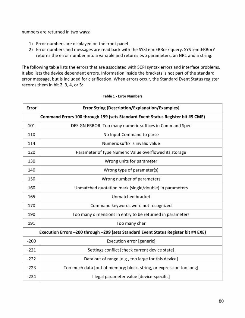
80
numbers are returned in two ways:
1) Error numbers are displayed on the front panel. 2) Error numbers and messages are read back with the SYSTem:ERRor? query. SYSTem:ERRor?
returns the error number into a variable and returns two parameters, an NR1 and a string. The following table lists the errors that are associated with SCPI syntax errors and interface problems. It also lists the device dependent errors. Information inside the brackets is not part of the standard error message, but is included for clarification. When errors occur, the Standard Event Status register records them in bit 2, 3, 4, or 5:
Table 1 - Error Numbers
Error Error String [Description/Explanation/Examples]
Command Errors 100 through 199 (sets Standard Event Status Register bit #5 CME)
101 DESIGN ERROR: Too many numeric suffices in Command Spec
110 No Input Command to parse
114 Numeric suffix is invalid value
120 Parameter of type Numeric Value overflowed its storage
130 Wrong units for parameter
140 Wrong type of parameter(s)
150 Wrong number of parameters
160 Unmatched quotation mark (single/double) in parameters
165 Unmatched bracket
170 Command keywords were not recognized
190 Too many dimensions in entry to be returned in parameters
191 Too many char
Execution Errors –200 through –299 (sets Standard Event Status Register bit #4 EXE)
-200 Execution error [generic]
-221 Settings conflict [check current device state]
-222 Data out of range [e.g., too large for this device]
-223 Too much data [out of memory; block, string, or expression too long]
-224 Illegal parameter value [device-specific]
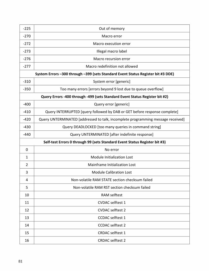
81
-225 Out of memory
-270 Macro error
-272 Macro execution error
-273 Illegal macro label
-276 Macro recursion error
-277 Macro redefinition not allowed
System Errors –300 through –399 (sets Standard Event Status Register bit #3 DDE)
-310 System error [generic]
-350 Too many errors [errors beyond 9 lost due to queue overflow]
Query Errors -400 through -499 (sets Standard Event Status Register bit #2)
-400 Query error [generic]
-410 Query INTERRUPTED [query followed by DAB or GET before response complete]
-420 Query UNTERMINATED [addressed to talk, incomplete programming message received]
-430 Query DEADLOCKED [too many queries in command string]
-440 Query UNTERMINATED [after indefinite response]
Self-test Errors 0 through 99 (sets Standard Event Status Register bit #3)
0 No error
1 Module Initialization Lost
2 Mainframe Initialization Lost
3 Module Calibration Lost
4 Non-volatile RAM STATE section checksum failed
5 Non-volatile RAM RST section checksum failed
10 RAM selftest
11 CVDAC selftest 1
12 CVDAC selftest 2
13 CCDAC selftest 1
14 CCDAC selftest 2
15 CRDAC selftest 1
16 CRDAC selftest 2
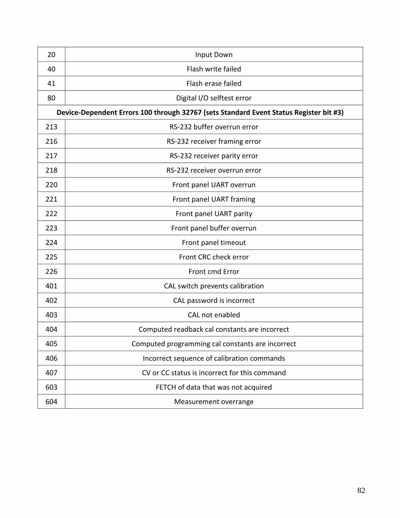
82
20 Input Down
40 Flash write failed
41 Flash erase failed
80 Digital I/O selftest error
Device-Dependent Errors 100 through 32767 (sets Standard Event Status Register bit #3)
213 RS-232 buffer overrun error
216 RS-232 receiver framing error
217 RS-232 receiver parity error
218 RS-232 receiver overrun error
220 Front panel UART overrun
221 Front panel UART framing
222 Front panel UART parity
223 Front panel buffer overrun
224 Front panel timeout
225 Front CRC check error
226 Front cmd Error
401 CAL switch prevents calibration
402 CAL password is incorrect
403 CAL not enabled
404 Computed readback cal constants are incorrect
405 Computed programming cal constants are incorrect
406 Incorrect sequence of calibration commands
407 CV or CC status is incorrect for this command
603 FETCH of data that was not acquired
604 Measurement overrange

83
22820 Savi Ranch Parkway Yorba Linda, CA 92887 www.bkprecision.com
© 2015-2016 B&K Precision Corp.
v051118


![F.Y. B.A. [ EXTERNAL ] May-June-2015 2014-2015results.indiaresults.com/.../notification/pdf/F1501TO200020151102.pdf · 8614 - psychology paper - i 100 aoo 8615 - psychology paper](https://img.pdfslide.us/doc/110x75/5b5bfa807f8b9a2d458eba43/fy-ba-external-may-june-2015-2014-8614-psychology-paper-i-100-aoo.jpg)