Embed Size (px)
Citation preview
Instructions 95-8616Electrochemical Toxic Gas DetectorGT3000 SeriesIncludes Transmitter (GTX) and Sensor Module (GTS)
8.2 Rev: 2/12 95-8616
Description . . . . . . . . . . . . . . . . . . . . . . . . . . . . . . 1
Gts sensor Module . . . . . . . . . . . . . . . . . . . . . . 1GtX transmitter . . . . . . . . . . . . . . . . . . . . . . . . . . 2real time clock . . . . . . . . . . . . . . . . . . . . . . . . . . 2History/event Logs . . . . . . . . . . . . . . . . . . . . . . . . 2HArt communication . . . . . . . . . . . . . . . . . . . . . 3Magnetic switch . . . . . . . . . . . . . . . . . . . . . . . . . . 3LeDs . . . . . . . . . . . . . . . . . . . . . . . . . . . . . . . . . . 3
specificAtions . . . . . . . . . . . . . . . . . . . . . . . . . . . 4
iMportAnt sAfety notes . . . . . . . . . . . . . . . . . . 5
instALLAtion . . . . . . . . . . . . . . . . . . . . . . . . . . . . . . 6
identification of Vapor(s) to be Detected . . . . . . . 6identification of Detector Mounting Locations . . . 6Device Mounting orientation . . . . . . . . . . . . . . . . 6Detector installation . . . . . . . . . . . . . . . . . . . . . . . 7sensor termination Box . . . . . . . . . . . . . . . . . . . . 7
wirinG . . . . . . . . . . . . . . . . . . . . . . . . . . . . . . . . . . . 7
power supply requirements . . . . . . . . . . . . . . . . 7wiring cable requirements . . . . . . . . . . . . . . . . . 7intrinsic safety Barriers . . . . . . . . . . . . . . . . . . . . 8Guidelines for intrinsic safety wiring . . . . . . . . . . 8wiring procedure . . . . . . . . . . . . . . . . . . . . . . . . . 8
cALiBrAtion . . . . . . . . . . . . . . . . . . . . . . . . . . . . . 12
Gt3000 calibration . . . . . . . . . . . . . . . . . . . . . . 12calibration procedure . . . . . . . . . . . . . . . . . . . . . 13
MAintenAnce . . . . . . . . . . . . . . . . . . . . . . . . . . . . 14
routine inspection . . . . . . . . . . . . . . . . . . . . . . . 14sensor Module replacement . . . . . . . . . . . . . . . 14
DeVice repAir AnD return . . . . . . . . . . . . . . . 15
orDerinG inforMAtion . . . . . . . . . . . . . . . . . . 15
Gts toxic Gas sensors . . . . . . . . . . . . . . . . . . . 15calibration Kits for toxic Gas sensors . . . . . . . . 15Misc . parts . . . . . . . . . . . . . . . . . . . . . . . . . . . . . 15
AppenDiX A — sensor coMpArison / cross sensitiVity . . . . . . . . . . . . 18
AppenDiX B — HArt coMMunicAtion . . . . . . . . . . 20
AppenDiX c — controL DrAwinGs . . . . . . . . . . . 22
Table of Contents

INSTRUCTIONS
Electrochemical Toxic Gas Detector
GT3000 Series
Includes Transmitter (GTX)
and Sensor Module (GTS)
8.2 ©Detector Electronics Corporation 2012 Rev: 2/12 95-8616
ImportantBe sure to read and understand the entire instruction manual before installing or operating the gas detection system. This product is intended to provide early warning of the presence of a toxic or explosive gas mixture. Proper device installation, operation, and maintenance are required to ensure safe and effective operation. If this equipment is used in a manner not specified in this manual, safety protection may be impaired.
Description
The GT3000 Electrochemical Gas Detector is an intelligent stand-alone industrial gas detector, designed to provide continuous monitoring of the atmosphere for hazardous gas leaks or oxygen depletion. It is fully performance tested and approved by Factory Mutual. Refer to Appendix A for individual gas specifications.
The GT3000 Gas Detector consists of a replaceable sensor module (Model GTS) connected to a transmitter module (Model GTX). A single transmitter is compatible with all GTS sensor modules. A variety of electrochemical sensor models are available in various concentration ranges.
The GT3000 is a 2-wire device that generates a 4-20 mA output signal with HART communication that is proportional to the concentration of the target gas.
The GT3000 is compatible with FlexVu® Model UD10 and UD20 Universal Display Units, as well as other devices
that are able to monitor a linear 4-20 mA dc signal. All alarm functions are provided by the monitoring device.
The GT3000 is designed and approved as a stand alone unit for use in hazardous locations. It is suitable for outdoor applications that require IP66 rating and uses a hydrophobic filter that is easily replaced without opening the device or use of tools. The GT3000 is furnished as either explosion-proof or intrinsically safe.
The GT3000 supports local one-person calibration with the use of a magnet and on-board LED.
GTS SENSOR MODUlE
The GTS’s electrochemical sensor cell uses capillary diffusion barrier technology for monitoring gas concentrations in ambient air.
live Maintenance
The hot swappable GTS sensor module is intrinsically safe and allows live maintenance while under power, without de-classifying the hazardous area. When the sensor is removed, the transmitter generates a fault output. If a new sensor of the same type and range is installed, the fault self-clears. However, if the type or range of the new sensor module does not match the old, the transmitter generates a fault until a successful calibration or acceptance of the new sensor type is completed. For additional information regarding Live Maintenance, refer to “Sensor Module Replacement” in the Maintenance section of this manual.
Sensor Module(GTS)
Transmitter(GTX)
Detector (GT3000)
28.2 95-8616
Automatic Sensor Module Recognition
The transmitter provides automatic gas sensor recognition, allowing the operator to access the following information via HART, or a UD10 or UD20 Universal display:
•Dateofmanufactureofthesensormodule
•Sensormoduleserialnumber
•Gastype
•Measurementrange
The sensor module is factory programmed for the gas type and measurement range. When the sensor module powers up, the transmitter reads and acknowledges the gas type and measurement range.
GTX TRANSMITTER
The transmitter output is a linear 4-20 mA dc signal with HART communication that directly corresponds to 0-100 % full scale.
A 3.8 mA output indicates sensor calibration in progress (17.3 mA for O2 sensor) and an output of 3.6 mA or less indicates a fault condition.
Priority of output signals from highest to lowest is:
1Calibration
(In progress)
2 Fault
3 Gas Level
Transmitter Wiring
The GTX transmitter is a two-wire loop powered device that uses a three-wire cable (power, signal, and earth ground) for connecting to a controller or monitoring device. The use of shielded cable is required.
REAl TIME ClOCk (RTC)
The GTX transmitter has a real time clock with battery back-up, that is used for time stamping the event logs. The time and date are set and read using a UD10/UD20 Universal Display Unit, a HART communication device, or AMS software. The time stamp on the logs will not be correct if the RTC in the transmitter is not set correctly.
HISTORY/EvENT lOGS
Both the transmitter and sensor are able to store 256 history logs, which are saved in non-volatile memory and retained through power cycles. A UD10/UD20 Universal Display Unit, a HART communication device, or AMS software is required to view the history logs.
Sensor logging Capability
The sensor module logs the following operating parameters in non-volatile memory:
• RunningHours - The sensor module maintains the total operating hours, and cannot be reset.
•Min/Max Temperature - The sensor module maintains the minimum and maximum temperatures with a date and time stamp.
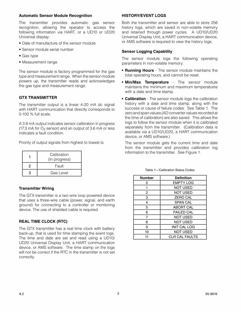
• Calibration - The sensor module logs the calibration history with a date and time stamp, along with the success or cause of failure codes. See Table 1. The zero and span values (AD converter values recorded at the time of calibration) are also saved. This allows the logs to follow the sensor module when it is calibrated separately from the transmitter. (Calibration data is available via a UD10/UD20, a HART communication device, or AMS software.)
The sensor module gets the current time and date from the transmitter and provides calibration log information to the transmitter. See Figure 1.
Number Definition0 EMPTY LOG1 NOT USED2 NOT USED3 ZERO CAL4 SPAN CAL5 ABORT CAL6 FAILED CAL7 NOT USED8 NOT USED9 INIT CAL LOG10 NOT USED11 CLR CAL FAULTS
Table 1—Calibration Status Codes

38.2 95-8616
Transmitter logging Capability
The transmitter logs the following events with a time and date stamp:
•Power-up
•Sensorchange
•AllFaults.
HART COMMUNICATION
The transmitter supports HART communication on the 4-20 mA loop. This allows for configuration capability and provides device status information, calibration, and diagnostics capabilities. The GT3000 is compatible with HART interface devices such as a HART handheld communicator, the Det-Tronics UD10 or UD20 Display Unit, or an AMS system. (See Appendix B for HART menu structure.)
MAGNETIC SWITCH
The GT3000 is furnished with an internal magnetic reed switch as part of the user interface. The magnetic switch allows the user to initiate calibration by momentarily placing a magnet against the housing at the designated location. See Figure 2.
lEDs
The GT3000 has one green and one yellow LED (See Figure 3). The LEDs are used to signal normal, calibration, and fault conditions. See Table 2.
NoTeThe GT3000 does not have alarm setpoints and, therefore, does not have a red LeD.
GREEN LED (ON)
YELLOW LED (OFF)
A2450
Figure 3— Location of LEDs on GT3000 Gas Detector
MAGNETICSWITCH
B2443
Figure 2—Location of Magnetic Switch on GT3000 Detector
Table 2—LEDs and Analog Output During Various Operating Conditions
Function Green lED Yellow lEDAnalog
4-20 Signal Output
Warm-up* Single Flash On < 3.6
Normal Operation
Steady On Off 4-20
Fault Condition
Off On < 3.6
Calibration Off See Table 5 3.8**No Power Off Off 0
*Warm-up time can last up to 150 seconds.**O2 sensor generates 17.3 mA during calibration.
Transmitter
RTC
Event Logs
Sensor Module
Calibration Logs
GT3000Gas Detector
HART Interface
Transmitter reads calibration logs
from sensor
Transmitter updatessensor module
time / date
Figure 1—GT3000 Logging
48.2 95-8616
specifications
SENSOR AND TRANSMITTER
AVAILABLE SENSORS—Refer to Appendix A.
CROSS SENSITIVITY—See Appendix A for Cross Sensitivity information.
CALIBRATION—Sensors are calibrated at the factory. Gas type and range are read by the transmitter. Field calibration is initiated at the detector, at the UD10/UD20 Universal Display Unit, or by some other HART interface device.
OPERATING VOLTAGE—24 volts dc nominal. (12 Vdc minimum, 30 Vdc maximum). Maximum ripple is 2 volts peak-to-peak.If using the HART function, the installation must comply with the HART power standard.
POWER CONSUMPTION—0.8 watt maximum @ 30 Vdc.
CURRENT OUTPUT—
•4-20mA(Normaloperatingmode).
•3.8mAindicatescalibratemode.
•3.6mAorlessindicatesafaultcondition.
MAXIMUM LOOP RESISTANCE—300 ohms at 18 Vdc, 600 ohms at 24 Vdc.
WIRING—The transmitter has flying leads, 20” long, 600V insulation.
Colors: Red = V+ Black = V– Green = earth ground
Gauge: 22 AWG (red and black) 16 AWG (green).
WARM-UP—Warm-up time can last up to 150 seconds.
OPERATING TEMPERATURE—See Appendix A.
STORAGE TEMPERATURE—Transmitter: –55°C to +75°C (–67°F to +167°F) Sensor: 0°C to +20°C (+32°F to +68°F). Ideal: +4°C to +10°C (+39°F to +50°F).
HUMIDITY RANGE—15 to 90% RH.
PRESSURE RANGE—Atmospheric ±10%.
INGRESS PROTECTION—IP66.
ELECTRO-MAGNETIC COMPATIBILITY—EMC Directive 2004/108/ECEN55011(Emissions)EN50270(Immunity).
THREAD OPTIONS—3/4"NPTorM25.
ENCLOSURE MATERIAL—GTX Transmitter: 316 Stainless SteelGTS Sensor Module: PPA (30% carbon filled).
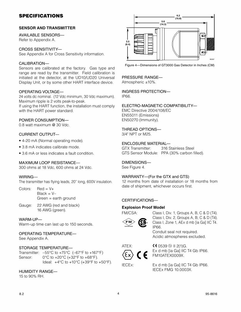
DIMENSIONS—See Figure 4.
WARRANTY—(For the GTX and GTS)12 months from date of installation or 18 months from date of shipment, whichever occurs first.
CERTIFICATIONS—
ExplosionProofModelFM/CSA: Class I, Div. 1, Groups A, B, C & D (T4). Class I, Div. 2, Groups A, B, C & D (T4). Class I, Zone 1, AEx d mb [ia Ga] IIC T4. IP66. Conduit seal not required. Acidic atmospheres excluded.
ATEX: 0539 FMAPPROVED
® II 2(1)G. Ex d mb [ia Ga] IIC T4 Gb IP66. FM10ATEX0009X.
IECEx: Ex d mb [ia Ga] IIC T4 Gb IP66. IECEx FMG 10.0003X.
Figure 4—Dimensions of GT3000 Gas Detector in Inches (CM)
2.5(6.4)
6.2(15.8)
5.6(14.3)
B2397
FMAPPROVED
®FMAPPROVED
®
FMAPPROVED
®
58.2 95-8616
NoTeThe GTX Toxic Gas Transmitter module shall be connected directly to a junction box suitable for the area of installation to provide protection for the flying leads.
NoTeConsideration must be given to overall Gas System Performance Requirements.
IntrinsicallySafeModel
FM: IS Class I, Div. 1, Groups A, B, C & D (T4). Class I, Zone 0, AEx ia IIC (T4). PerformanceverifiedperANSI/ISA
92.0.01. IP66.
CSA: Class I, Div. 1 & 2, Groups A, B, C & D (T4). IP66.
ATEX: 0539 II 1 Ex ia IIC T4 Ga IP66. FM08ATEX0045X.
IECEx: Ex ia IIC T4 Ga IP66. IECEx FMG 08.0005X.
NoTeIn order to maintain the intrinsically safe rating of the transmitter, the device must be powered through an approved I.S. barrier.
For a list of recommended barrier models, refer to Tables 3 and 4. For additional information regarding proper I.S. installation, refer to the Control Drawings in Appendix C of this manual.
SILAPPRovAL
IEC 61508Certified SIL 2 Capable.SIL Certification includes H2S and O2 GTS models only.For specific information regarding SIL models, refer to the GT3000 Safety Reference Manual, form 95-8685.
important safety notes
CaUtIonThe wiring procedures in this manual are intended to ensure proper functioning of the device under normal conditions. However, because of the many variations in wiring codes and regulations, total compliance to these ordinances cannot be guaranteed. Be certain that all wiring complies with the NeC as well as all local codes. If in doubt, consult the authority having jurisdiction before wiring the system. Installation must be done by a properly trained person.
CaUtIonThis product has been tested and approved for use in hazardous areas. However, it must be properly installed and used only under the conditions specified within this manual and the specific approval certificates. Any device modification, improper installation, or use in a faulty or incomplete configuration will render warranty and product certifications invalid.
CaUtIonThe GT3000 contains no field repairable components. User performed service is limited to replacement of the gas sensor module.
LIabILItIesThe manufacturer’s warranty for this product is void, and all liability for proper function of the detector is irrevocably transferred to the owner or operator in the event that the device is serviced or repaired by personnel not employed or authorized by Detector electronics Corporation, or if the device is used in a manner not conforming to its intended use.
CaUtIonobserve precautions for handling electrostatic sensitive devices.
NoTeThe sensor housing is made of Polyphthalamide (PPA), 30% carbon filled (Material Manufacturer RTP). Questions regarding chemical resistance should be addressed to:
www.det-tronics.com US toll free 800-468-3244 or 952-941-5665
FMAPPROVED
®
FMAPPROVED
®
FMAPPROVED
®

68.2 95-8616
installation
The gas detector can be installed either in a stand-alone configuration as a loop powered device, or it can be connected to a UD10/UD20 Universal Display Unit.
NoTeThe gas detector housing must be electrically connected to earth ground. A dedicated earth ground wire is provided on the transmitter for connection to earth ground or to a grounded housing.
The detector must always be installed per local installation code.
Before installing the gas detector, define the following application details:
IdEnTIfICATIonofvAPoR(S)TobEdETECTEd
It is necessary to always identify the vapor(s) of interest at the job site. In addition, the fire hazard properties of the vapor, such as vapor density, flashpoint, and vapor pressure should be identified and used to assist in selecting the optimum detector mounting location within the area.
IDENTIFICATION OF DETECTOR MOUNTING lOCATIONS
Identification of the most likely leak sources and leak accumulation areas is typically the first step in identifying the best detector mounting locations. In addition, identification of air current/wind patterns within the protected area is useful in predicting gas leak dispersion behavior. This information should be used to identify optimum sensor installation points.
If the vapor of interest is lighter than air, place the sensor above the potential gas leak. Place the sensor close to thefloorforgasesthatareheavierthanair.Notethataircurrents may cause a gas that is slightly heavier than air to rise under some conditions. Heated gases may also exhibit the same phenomenon.
The most effective number and placement of detectors varies depending on the conditions on site. The individual designing the installation must often rely on experience and common sense to determine the detector quantity and best locations to adequately protectthearea.Notethatitistypicallyadvantageousto locate detectors where they are accessible for maintenance. Locations near excessive heat or vibration sources should be avoided if possible.
Final suitability of possible gas detector locations should be verified by a site survey. If any questions arise regarding installation, please contact the factory.
DEvICE MOUNTING ORIENTATION
The gas detector must be mounted in a vertical position only, with the sensor pointing down (See Figure 5).
ImportantThe sensor should be oriented with the LeDs facing forward so they are easily visible to personnel within the area. To ensure correct orientation (the LeDs are not visible when power is off), position the GND lug on the left hand side and the calibration notch to the front. Note that the LeDs are located directly above the calibration notch.
GREEN LED
CALIBRATION NOTCH
B2436
GND LUG
Figure 5—Correct Mounting Orientation for the GT3000

78.2 95-8616
DETECTOR INSTAllATION
3/4"nPTModels
3/4"NPTmodelshaveTaperedThreadsandnoLockNut.Installthesensorasfollows:
1. Screw the detector into the appropriate entry on the termination box. Ensure a minimum of 5 fully engagedthreads.UseofteflontapeonNPTthreadsis recommended to prevent thread damage.
2. When the detector gets tight, note the position of the LEDs,GNDlugandcalibrationnotchandadjustthedetector as required so that the LEDs will be easily visible.
M25 Models
M25models have Straight Threads and a Lock Nut.Install the detector as follows:
1. Screw the detector lock nut as far back as it will go, then screw the detector into the appropriate entry on the termination box. Ensure a minimum of 7 fully engaged threads.
2. With the detector in the desired position (LEDs visible as shown in Figure 5), tighten the lock nut against the termination box to hold the detector securely in place.
3. Tighten the set screws (minimum of two) to prevent movement of the lock nut. See Figure 6.
SEnSoRTERMInATIonbox
A Det-Tronics sensor termination box (Model STB) is required for installing the sensor in a stand alone configuration, or for installing the GT3000 remotely from the UD10/UD20 Universal Display Unit.
When installing the GT3000 remotely from a UD10/UD20, two-conductor shielded cable is required to prevent possible nuisance EMI/RFI. The maximum cable length between the GT3000 and the UD10/UD20 is 2000 ft.
WirinG
PowERSUPPLYREqUIREMEnTS
Calculate the total gas detection system power consumption rate in watts from cold start-up. Select a power supply with adequate capability for the calculated load. Ensure that the selected power supply provides sufficient regulated and filtered output power for the entire system. If a back-up power system is required, a float-type battery charging system is recommended. If an existing source of power is being utilized, verify that system requirements are met.
NoTeThe power supply must also meet the noise requirements for HART systems.
wIRIngCAbLEREqUIREMEnTS
Always use proper cabling type and diameter for input power as well as output signal wiring. 22 to 14 AWG shielded stranded copper wire is recommended.
Always install a properly sized, master power fuse or breaker on the system power circuit.
NoTeThe use of shielded cable in conduit or shielded armored cable is highly recommended. In applications where the wiring is installed in conduit, dedicated conduit is recommended. Avoid low frequency, high voltage, and non‑signaling conductors to prevent nuisance eMI problems.
CaUtIonThe use of proper conduit installation techniques, breathers, glands, and seals is required to prevent water ingress and/or maintain the explosion‑proof rating.
Set Screws
Figure 6—Location of Lock Nut and Set Screws (Metric Models Only)
88.2 95-8616
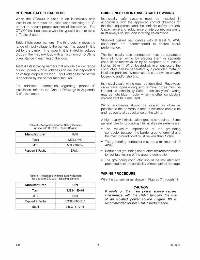
InTRInSICSAfETYbARRIERS
When the GT3000 is used in an intrinsically safe installation, care must be taken when selecting an I.S. barrier to ensure proper function of the device. The GT3000 has been tested with the types of barriers listed in Tables 3 and 4.
Table 3 lists zener barriers. The third column gives the range of input voltage to the barrier. The upper limit is set by the barrier. The lower limit is limited by voltage drops in the 4-20 mA loop with a maximum of 10 Ohms of resistance in each leg of the loop.
Table 4 lists isolating barriers that provide a wider range of input power supply voltages and are less dependent on voltage drops in the loop. Input voltage to the barrier is specified by the barrier manufacturer.
For additional information regarding proper IS installation, refer to the Control Drawings in Appendix C of this manual.
GUIDElINES FOR INTRINSIC SAFETY WIRING
Intrinsically safe systems must be installed in accordance with the approved control drawings for the field equipment and the intrinsic safety barriers. Capacitance and inductance of interconnecting wiring must always be included in wiring calculations.
Shielded twisted pair cables with at least 18 AWG conductors are recommended to ensure circuit performance.
The intrinsically safe conductors must be separated from all other wiring by placing them in separate conduits or raceways, or by an airspace of at least 2 inches (50 mm). When located within an enclosure, the conductors can be separated by a grounded metal or insulated partition. Wires must be tied down to prevent loosening and/or shorting.
Intrinsically safe wiring must be identified. Raceways, cable trays, open wiring, and terminal boxes must be labeled as Intrinsically Safe. Intrinsically safe wiring may be light blue in color when no other conductors colored light blue are used.
Wiring enclosures should be located as close as possible to the hazardous area to minimize cable runs and reduce total capacitance of the wiring.
A high quality intrinsic safety ground is required. Some general rules for grounding intrinsically safe systems are:
• The maximum impedance of the groundingconductor between the barrier ground terminal and the main ground point must be less than 1 ohm.
• Thegroundingconductormustbeaminimumof12AWG.
• Redundantgroundingconductorsarerecommendedto facilitate testing of the ground connection.
• Thegroundingconductor shouldbe insulatedandprotected from the possibility of mechanical damage.
wIRIngPRoCEdURE
Wire the transmitter as shown in Figures 7 through 12.
CaUtIonIf ripple on the main power source causes interference with the HART function, the use of an isolated power source (Figure 12) is recommended for best HART performance.
Manufacturer P/n
Turck MZB87PX
MTL MTL7787P+
Pepperl & Fuchs Z787.h
Table 3—Acceptable Intrinsic Safety Barriers for use with GT3000 – Zener Barriers
Manufacturer P/n
Turck IM33-11Ex-Hi
MTL 5541
Pepperl & Fuchs KCD2-STC-Ex1
Stahl 9160/13-10-11
Table 4—Acceptable Intrinsic Safety Barriers for use with GT3000 – Isolating Barriers
98.2 95-8616
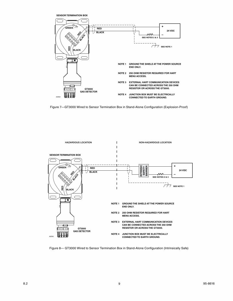
+
–24 VDC
A2502
NOTE 1 GROUND THE SHIELD AT THE POWER SOURCE END ONLY.
NOTE 2 250 OHM RESISTOR REQUIRED FOR HART MENU ACCESS.
NOTE 3 EXTERNAL HART COMMUNICATION DEVICES CAN BE CONNECTED ACROSS THE 250 OHM RESISTOR OR ACROSS THE GT3000.
NOTE 4 JUNCTION BOX MUST BE ELECTRICALLY CONNECTED TO EARTH GROUND.
BLACK
RED
SEE NOTES 2 & 3
SEE NOTE 1
GT3000GAS DETECTOR
SENSOR TERMINATION BOX
RED
RE
D
BLACK
BLACK
GREEN
Figure 7—GT3000 Wired to Sensor Termination Box in Stand-Alone Configuration (Explosion-Proof)
+
–24 VDC
A2530
NOTE 1 GROUND THE SHIELD AT THE POWER SOURCE END ONLY.
NOTE 2 250 OHM RESISTOR REQUIRED FOR HART MENU ACCESS.
NOTE 3 EXTERNAL HART COMMUNICATION DEVICES CAN BE CONNECTED ACROSS THE 250 OHM RESISTOR OR ACROSS THE GT3000.
NOTE 4 JUNCTION BOX MUST BE ELECTRICALLY CONNECTED TO EARTH GROUND.
BLACK
RED
SEE NOTES 2 & 3
SEE NOTE 1
GT3000GAS DETECTOR
SENSOR TERMINATION BOX
RED
RE
D
BLACK
BLACK
GREEN
HAZARDOUS LOCATION NON-HAZARDOUS LOCATIONIN
TR
INS
ICS
AF
ET
YB
AR
RIE
R
Figure 8— GT3000 Wired to Sensor Termination Box in Stand-Alone Configuration (Intrinsically Safe)
108.2 95-8616
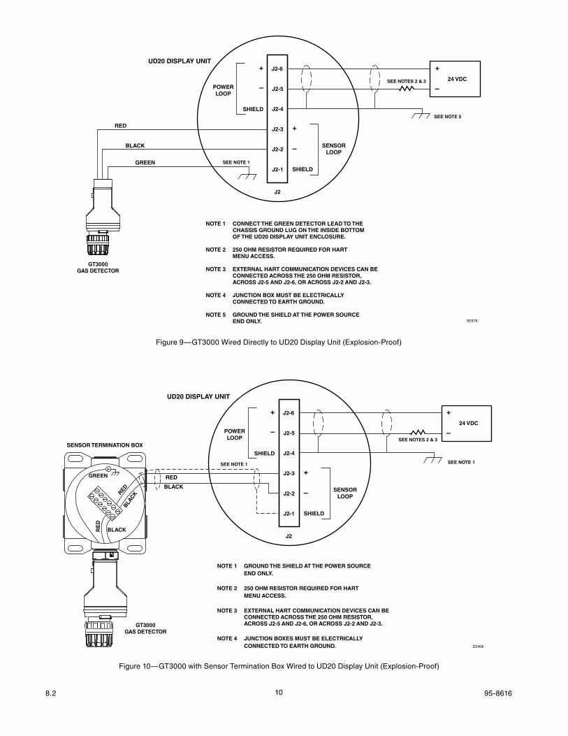
Figure 9—GT3000 Wired Directly to UD20 Display Unit (Explosion-Proof)
+
–24 VDC
UD20 DISPLAY UNIT
B2478
J2-6
J2-5
J2-4
J2-3
J2-2
J2-1
J2
NOTE 1 CONNECT THE GREEN DETECTOR LEAD TO THE CHASSIS GROUND LUG ON THE INSIDE BOTTOM OF THE UD20 DISPLAY UNIT ENCLOSURE.
NOTE 2 250 OHM RESISTOR REQUIRED FOR HART MENU ACCESS.
NOTE 3 EXTERNAL HART COMMUNICATION DEVICES CAN BE CONNECTED ACROSS THE 250 OHM RESISTOR, ACROSS J2-5 AND J2-6, OR ACROSS J2-2 AND J2-3.
NOTE 4 JUNCTION BOX MUST BE ELECTRICALLY CONNECTED TO EARTH GROUND.
NOTE 5 GROUND THE SHIELD AT THE POWER SOURCE END ONLY.
SEE NOTES 2 & 3
SEE NOTE 5
GT3000GAS DETECTOR
+
+
–
–
SHIELD
SHIELD
SENSORLOOP
POWERLOOP
BLACK
RED
GREEN SEE NOTE 1
+
–24 VDC
UD20 DISPLAY UNIT
D2408
J2-6
J2-5
J2-4
J2-3
J2-2
J2-1
J2
NOTE 1 GROUND THE SHIELD AT THE POWER SOURCE END ONLY.
NOTE 2 250 OHM RESISTOR REQUIRED FOR HART MENU ACCESS.
NOTE 3 EXTERNAL HART COMMUNICATION DEVICES CAN BE CONNECTED ACROSS THE 250 OHM RESISTOR, ACROSS J2-5 AND J2-6, OR ACROSS J2-2 AND J2-3.
NOTE 4 JUNCTION BOXES MUST BE ELECTRICALLY CONNECTED TO EARTH GROUND.
BLACK
RED
SEE NOTE 1
SEE NOTES 2 & 3
SEE NOTE 1
GT3000GAS DETECTOR
SENSOR TERMINATION BOX
RED
RE
D
BLACK
BLACK
GREEN +
+
–
–
SHIELD
SHIELD
SENSORLOOP
POWERLOOP
Figure 10—GT3000 with Sensor Termination Box Wired to UD20 Display Unit (Explosion-Proof)
118.2 95-8616
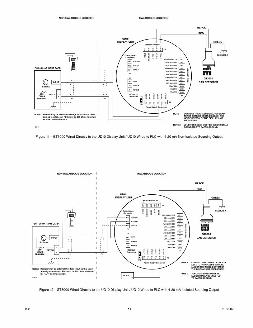
Figure 11—GT3000 Wired Directly to the UD10 Display Unit / UD10 Wired to PLC with 4-20 mA Non-Isolated Sourcing Output
GT3000
GAS DETECTOR
BLACK
RED
GREEN
SEE NOTE 1
NOTE 1 CONNECT THE GREEN DETECTOR LEAD TO THE CHASSIS GROUND LUG ON THE INSIDE BOTTOM OF THE DISPLAY UNIT ENCLOSURE.
NOTE 2 JUNCTION BOXES MUST BE ELECTRICALLY CONNECTED TO EARTH GROUND.C2453
NON-HAZARDOUS LOCATION HAZARDOUS LOCATION
Sensor Connector
Power Supply Connector
Output LoopConnector
MODBUSConnector
Rel
ay C
on
nec
tor
P1
J2
J3
J4
P2
4-20 mA +
4-20 mA –
SHIELD
COM
RS485 A
RS485 B
HIGH ALARM COM
HIGH ALARM NC
HIGH ALARM NO
AUX ALARM COM
AUX ALARM NC
AUX ALARM NO
LOW ALARM COM
LOW ALARM NC
LOW ALARM NO
FAULT COM
FAULT NC
FAULT NO
24 V
DC
–
24 V
DC
+
SH
IEL
D
24 V
DC
–
24 V
DC
+
SH
IEL
D
SH
IEL
D
CA
LIB
RA
TE
24 V
DC
–
4-20
mA
24 V
DC
+
P1-3
P1-2
P1-1
J2-3
J2-2
J2-1
J4-1
J4-2
J4-3
J4-4
J4-5
J4-6
J4-7
J4-8
J4-9
J4-10
J4-11
J4-12
J3-1
J3-2
J3-3
J3-4
J3-5
P2-
6
P2-
5
P2-
4
P2-
3
P2-
2
P2-
1
UD10 DISPLAY UNIT
24 VDC
INPUT
4-20 mA
PLC 4-20 mA INPUT CARD
–
+250
OHMSMINIMUM
Notes: Resistor may be external if voltage input card is used. Sinking resistance at PLC must be 250 ohms minimum for HART communication.
P12
Figure 12—GT3000 Wired Directly to the UD10 Display Unit / UD10 Wired to PLC with 4-20 mA Isolated Sourcing Output
GT3000
GAS DETECTOR
BLACK
RED
GREEN
SEE NOTE 1
NOTE 1 CONNECT THE GREEN DETECTOR LEAD TO THE CHASSIS GROUND LUG ON THE INSIDE BOTTOM OF THE DISPLAY UNIT ENCLOSURE.
NOTE 2 JUNCTION BOXES MUST BE ELECTRICALLY CONNECTED TO EARTH GROUND.C2479
NON-HAZARDOUS LOCATION HAZARDOUS LOCATION
Sensor Connector
Power Supply Connector
Output LoopConnector
MODBUSConnector
Rel
ay C
on
nec
tor
P1
J2
J3
J4
P2
4-20 mA +
4-20 mA –
SHIELD
COM
RS485 A
RS485 B
HIGH ALARM COM
HIGH ALARM NC
HIGH ALARM NO
AUX ALARM COM
AUX ALARM NC
AUX ALARM NO
LOW ALARM COM
LOW ALARM NC
LOW ALARM NO
FAULT COM
FAULT NC
FAULT NO
24 V
DC
–
24 V
DC
+
SH
IEL
D
24 V
DC
–
24 V
DC
+
SH
IEL
D
SH
IEL
D
CA
LIB
RA
TE
24 V
DC
–
4-20
mA
24 V
DC
+
P1-3
P1-2
P1-1
J2-3
J2-2
J2-1
J4-1
J4-2
J4-3
J4-4
J4-5
J4-6
J4-7
J4-8
J4-9
J4-10
J4-11
J4-12
J3-1
J3-2
J3-3
J3-4
J3-5
P2-
6
P2-
5
P2-
4
P2-
3
P2-
2
P2-
1
UD10 DISPLAY UNIT
24 VDC
24 VDC
INPUT
4-20 mA
PLC 4-20 mA INPUT CARD
–
–
+
+
250OHMS
MINIMUM
Notes: Resistor may be external if voltage input card is used. Sinking resistance at PLC must be 250 ohms minimum for HART communication.
P12
128.2 95-8616
calibration
gT3000CALIbRATIon
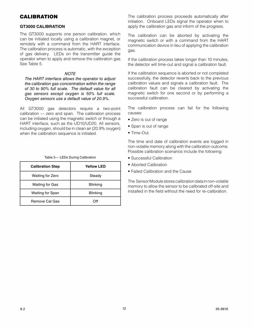
The GT3000 supports one person calibration, which can be initiated locally using a calibration magnet, or remotely with a command from the HART interface. The calibration process is automatic, with the exception of gas delivery. LEDs on the transmitter guide the operator when to apply and remove the calibration gas See Table 5.
NoTeThe HART interface allows the operator to adjust the calibration gas concentration within the range of 30 to 90% full scale. The default value for all gas sensors except oxygen is 50% full scale. oxygen sensors use a default value of 20.9%.
All GT3000 gas detectors require a two-point calibration — zero and span. The calibration process can be initiated using the magnetic switch or through a HART interface, such as the UD10/UD20. All sensors, including oxygen, should be in clean air (20.9% oxygen) when the calibration sequence is initiated.
The calibration process proceeds automatically after initiation. Onboard LEDs signal the operator when to apply the calibration gas and inform of the progress.
The calibration can be aborted by activating the magnetic switch or with a command from the HART communication device in lieu of applying the calibration gas.
If the calibration process takes longer than 10 minutes, the detector will time-out and signal a calibration fault.
If the calibration sequence is aborted or not completed successfully, the detector reverts back to the previous calibration values and signals a calibration fault. The calibration fault can be cleared by activating the magnetic switch for one second or by performing a successful calibration.
The calibration process can fail for the following causes:
•Zeroisoutofrange
•Spanisoutofrange
•Time-Out.
The time and date of calibration events are logged in non-volatile memory along with the calibration outcome. Possible calibration scenarios include the following:
•SuccessfulCalibration
•AbortedCalibration
•FailedCalibrationandtheCause
The Sensor Module stores calibration data in non-volatile memory to allow the sensor to be calibrated off-site and installed in the field without the need for re-calibration.
Calibration Step Yellow lED
Waiting for Zero Steady
Waiting for Gas Blinking
Waiting for Span Blinking
Remove Cal Gas Off
Table 5— LEDs During Calibration
138.2 95-8616
CALIbRATIonPRoCEdURE
NoTeWhen attaching or removing the calibration cup, push or pull the cup with a slight clockwise twist. Turning counterclockwise can cause the filter assembly on the GT3000 to loosen. If the filter assembly is inadvertently loosened, tighten it by hand (no tools required).
ToxicSensors
1. Clean air must be present at the GT3000 sensor module prior to initiating calibration. The use of bottled air is recommended.
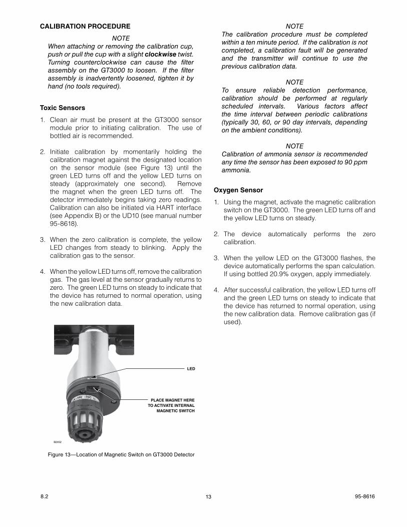
2. Initiate calibration by momentarily holding the calibration magnet against the designated location on the sensor module (see Figure 13) until the green LED turns off and the yellow LED turns on steady (approximately one second). Remove the magnet when the green LED turns off. The detector immediately begins taking zero readings. Calibration can also be initiated via HART interface (see Appendix B) or the UD10 (see manual number 95-8618).
3. When the zero calibration is complete, the yellow LED changes from steady to blinking. Apply the calibration gas to the sensor.
4. When the yellow LED turns off, remove the calibration gas. The gas level at the sensor gradually returns to zero. The green LED turns on steady to indicate that the device has returned to normal operation, using the new calibration data.
NoTeThe calibration procedure must be completed within a ten minute period. If the calibration is not completed, a calibration fault will be generated and the transmitter will continue to use the previous calibration data.
NoTeTo ensure reliable detection performance, calibration should be performed at regularly scheduled intervals. Various factors affect the time interval between periodic calibrations (typically 30, 60, or 90 day intervals, depending on the ambient conditions).
NoTeCalibration of ammonia sensor is recommended any time the sensor has been exposed to 90 ppm ammonia.
oxygenSensor
1. Using the magnet, activate the magnetic calibration switch on the GT3000. The green LED turns off and the yellow LED turns on steady.
2. The device automatically performs the zero calibration.
3. When the yellow LED on the GT3000 flashes, the device automatically performs the span calculation. If using bottled 20.9% oxygen, apply immediately.
4. After successful calibration, the yellow LED turns off and the green LED turns on steady to indicate that the device has returned to normal operation, using the new calibration data. Remove calibration gas (if used).
LED
PLACE MAGNET HERETO ACTIVATE INTERNAL
MAGNETIC SWITCH
B2452
Figure 13—Location of Magnetic Switch on GT3000 Detector
148.2 95-8616
maintenance
NoTeRefer to the GT3000 Safety Manual (number 95‑8685) for speci f ic requi rements and recommendations applicable to the proper installation, operation, and maintenance of all SIL‑Certified GT3000 gas detectors.
RoUTInEInSPECTIon
The gas inlet to the sensor should be inspected periodically, or during scheduled maintenance, to ensure that external obstructions such as plastic bags, litter, heavy oil and tar, paint, mud, snow, or other materials do not block the flow of gas to the sensor, thereby impairing the performance of the device.
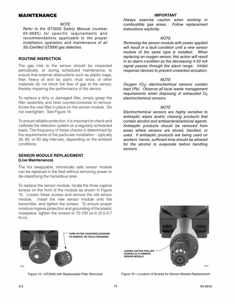
To replace a dirty or damaged filter, simply grasp the filter assembly and twist counterclockwise to remove. Screw the new filter in place on the sensor module. Do not overtighten. See Figure 14.
To ensure reliable protection, it is important to check and calibrate the detection system on a regularly scheduled basis. The frequency of these checks is determined by the requirements of the particular installation – typically 30, 60, or 90 day intervals, depending on the ambient conditions.
SEnSoRModULEREPLACEMEnT (live Maintenance)
The hot swappable, intrinsically safe sensor module can be replaced in the field without removing power or de-classifying the hazardous area.
To replace the sensor module, locate the three captive screws on the front of the module as shown in Figure 15. Loosen these screws and remove the old sensor module. Install the new sensor module onto the transmitter, and tighten the screws. To ensure proper moisture ingress protection and grounding of the plastic nosepiece, tighten the screws to 70-100 oz-in (0.5-0.7 N-m).
ImportantAlways exercise caution when working in combustible gas areas. Follow replacement instructions explicitly.
NoTeRemoving the sensor module with power applied will result in a fault condition until a new sensor module of the same type is installed. When replacing an oxygen sensor, this action will result in an alarm condition as the decreasing 4‑20 mA signal passes through the alarm range. Inhibit response devices to prevent unwanted actuation.
NoTeoxygen (o2) electrochemical sensors contain lead (Pb). observe all local waste management requirements when disposing of exhausted o2 electrochemical sensors.
NoTeelectrochemical sensors are highly sensitive to antiseptic wipes and/or cleaning products that contain alcohol and antibacterial/antiviral agents. Antiseptic products should be removed from areas where sensors are stored, handled, or used. If antiseptic products are being used on workers' hands, sufficient time should be allowed for the alcohol to evaporate before handling sensors.
LOOSEN CAPTIVE PHILLIPSSCREWS (3) TO REMOVE SENSOR MODULE.
B2451
Figure 15—Location of Screws for Sensor Module ReplacementFigure 14—GT3000 with Replaceable Filter Removed
TURN FILTER COUNTERCLOCKWISE TO REMOVE. NO TOOLS REQUIRED.
A2481

158.2 95-8616
DeVice repair anD retUrn
Prior to returning devices, contact the nearest local Detector Electronics office so that a Return Material Identification (RMI) number can be assigned. A writtenstatementdescribingthemalfunctionmustaccompany the returned device or component to assist and expedite finding the root causeof thefailure.
Pack the unit properly. Always use sufficient packing material. Where applicable, use an antistatic bag as protection from electrostatic discharge.
NoTeInadequate packaging that ultimately causes damage to the returned device during shipment will result in a service charge to repair the damage incurred during shipment.
Return all equipment transportation prepaid to the factory in Minneapolis.
NoTeIt is highly recommended that a complete spare be kept on hand for field replacement to ensure continuous protection.
orDerinG information
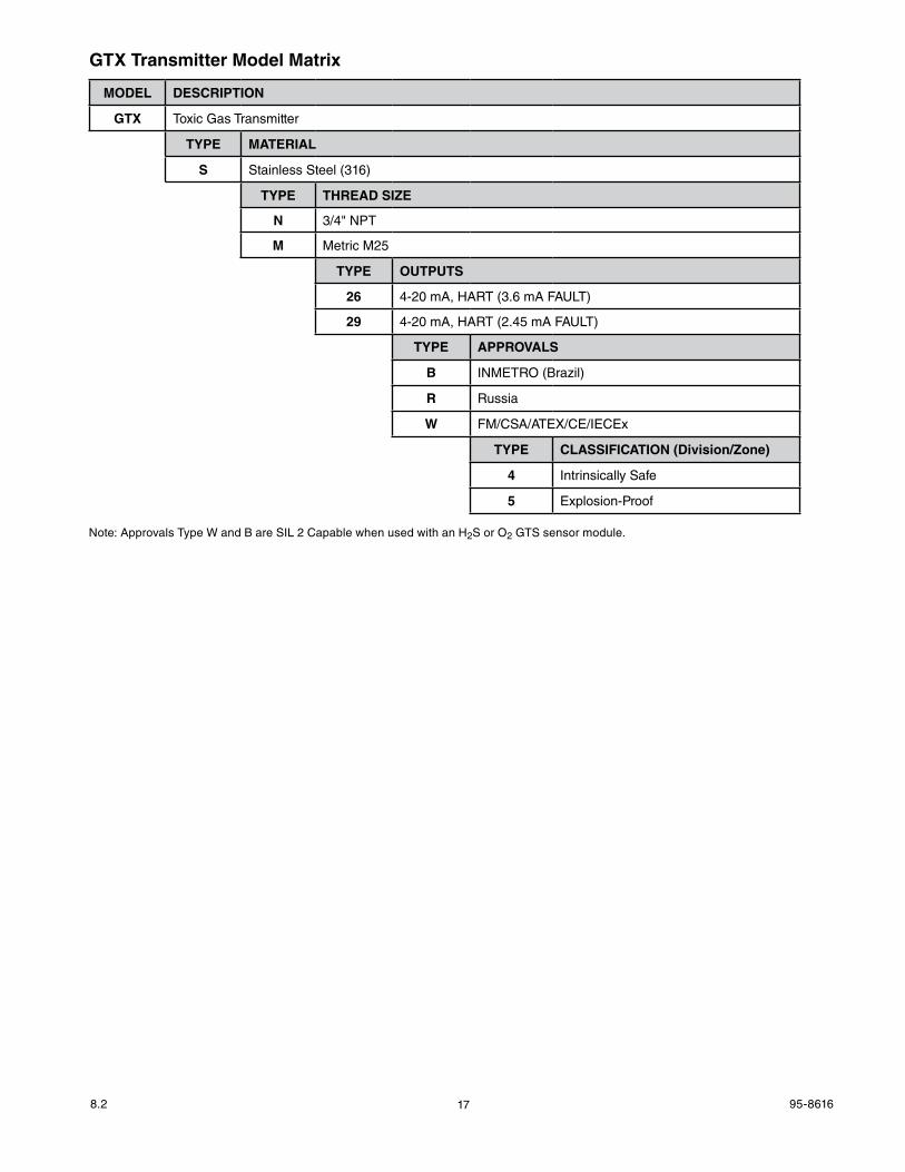
Sensor module (GTS) and transmitter (GTX) must be ordered separately. Refer to the Transmitter and Sensor Model Matrix on next page for ordering details.
GTS TOXIC GAS SENSORS
Gas Concentration
Hydrogen Sulfide (H2S) 0-20 ppm
Hydrogen Sulfide (H2S) 0-50 ppm
Hydrogen Sulfide (H2S) 0-100 ppm
Oxygen (O2)* 0-25% V/V
Carbon Monoxide (CO) 0-100 ppm
Carbon Monoxide (CO) 0-500 ppm
Ammonia(NH3) 0-100, or 0-500 ppm
Sulfur Dioxide (SO2) 0-20 ppm
Sulfur Dioxide (SO2) 0-100 ppm
Chlorine (Cl2) 0-10 ppm
Hydrogen (H2) 0-1000 ppm
NitrogenDioxide(NO2) 0-20 ppm
*Oxygen detector for O2 depletion (< 21% V/V) only.
CALIbRATIonKITSfoRToxICgASSEnSoRS
Partnumber gas/Concentration010274-001 H2S / 10 ppm 010274-002 H2S / 25 ppm 010274-003 H2S / 50 ppm010274-008 H2 / 500 ppm010274-009 O2 / 20.9%010274-010 CO / 50 ppm010274-011 CO / 250 ppm010274-005 NH3 / 50 ppm010274-006 NH3 / 250 ppm010274-013 SO2 / 10 ppm010274-014 SO2 / 50 ppm010274-004 Cl2 / 5 ppm010274-016 NO2 / 10 ppmReplacement gas cylinders for all calibration kits are available.
MISC.PARTS
Partnumber description009737-001 Calibration Cup009700-001 Magnetic Tool101678-007 3 Foot Tubing107427-059 Calibration Cup O-ring162552-001 Regulator, 1 LPM009640-001 Replaceable Filter
ASSISTANCEFor assistance in ordering a system to meet the needs of a specific application, contact:
Detector Electronics Corporation6901 West 110th StreetMinneapolis, Minnesota 55438 USAOperator: (952) 941-5665 or (800) 765-FIRECustomer Service: (952) 946-6491Fax: (952) 829-8750Web site: www.det-tronics.comE-mail: [email protected]
168.2 95-8616
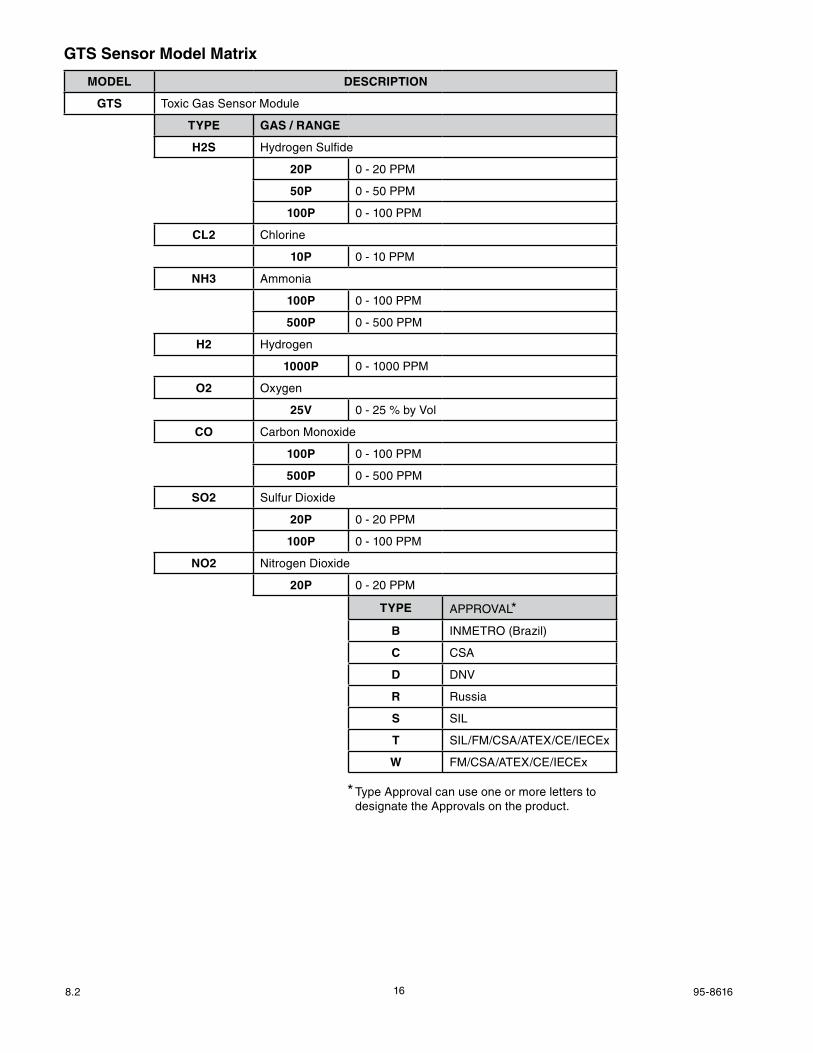
gTSSensorModelMatrix
MODEl dESCRIPTIon
GTS Toxic Gas Sensor Module
TYPE GAS / RANGE
H2S Hydrogen Sulfide
20P 0 - 20 PPM
50P 0 - 50 PPM
100P 0 - 100 PPM
Cl2 Chlorine
10P 0 - 10 PPM
NH3 Ammonia
100P 0 - 100 PPM
500P 0 - 500 PPM
H2 Hydrogen
1000P 0 - 1000 PPM
O2 Oxygen
25v 0 - 25 % by Vol
CO Carbon Monoxide
100P 0 - 100 PPM
500P 0 - 500 PPM
SO2 Sulfur Dioxide
20P 0 - 20 PPM
100P 0 - 100 PPM
NO2 Nitrogen Dioxide
20P 0 - 20 PPM
TYPE APPROVAL*
b INMETRO (Brazil)
C CSA
D DNV
R Russia
S SIL
T SIL/FM/CSA/ATEX/CE/IECEx
W FM/CSA/ATEX/CE/IECEx
* Type Approval can use one or more letters to designate the Approvals on the product.
178.2 95-8616
gTxTransmitterModelMatrix
MODEl dESCRIPTIon
GTX Toxic Gas Transmitter
TYPE MATERIAl
S Stainless Steel (316)
TYPE THREAD SIZE
N 3/4" NPT
M Metric M25
TYPE oUTPUTS
26 4-20 mA, HART (3.6 mA FAULT)
29 4-20 mA, HART (2.45 mA FAULT)
TYPE APPRovALS
b INMETRO (Brazil)
R Russia
W FM/CSA/ATEX/CE/IECEx
TYPE ClASSIFICATION (Division/Zone)
4 Intrinsically Safe
5 Explosion-Proof
Note: Approvals Type W and B are SIL 2 Capable when used with an H2S or O2 GTS sensor module.
188.2 95-8616
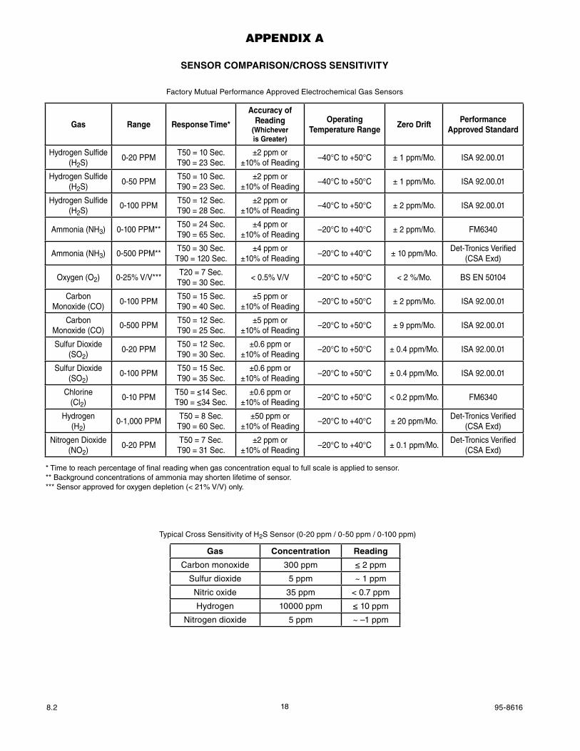
appenDix a
SEnSoRCoMPARISon/CRoSSSEnSITIvITY
Typical Cross Sensitivity of H2S Sensor (0-20 ppm / 0-50 ppm / 0-100 ppm)
Gas Concentration Reading
Carbon monoxide 300 ppm ≤ 2 ppm
Sulfur dioxide 5 ppm ~ 1 ppm
Nitric oxide 35 ppm < 0.7 ppm
Hydrogen 10000 ppm ≤ 10 ppm
Nitrogen dioxide 5 ppm ~ –1 ppm
Factory Mutual Performance Approved Electrochemical Gas Sensors
* Time to reach percentage of final reading when gas concentration equal to full scale is applied to sensor. ** Background concentrations of ammonia may shorten lifetime of sensor.*** Sensor approved for oxygen depletion (< 21% V/V) only.
Gas Range Response Time*
AccuracyofReading
(Whicheveris Greater)
Operating Temperature Range
ZerodriftPerformance
Approved Standard
Hydrogen Sulfide (H2S)
0-20 PPMT50 = 10 Sec.T90 = 23 Sec.
±2 ppm or±10% of Reading
–40°C to +50°C ± 1 ppm/Mo. ISA 92.00.01
Hydrogen Sulfide (H2S)
0-50 PPMT50 = 10 Sec.T90 = 23 Sec.
±2 ppm or±10% of Reading
–40°C to +50°C ± 1 ppm/Mo. ISA 92.00.01
Hydrogen Sulfide (H2S)
0-100 PPMT50 = 12 Sec.T90 = 28 Sec.
±2 ppm or±10% of Reading
–40°C to +50°C ± 2 ppm/Mo. ISA 92.00.01
Ammonia (NH3) 0-100 PPM**T50 = 24 Sec.T90 = 65 Sec.
±4 ppm or±10% of Reading
–20°C to +40°C ± 2 ppm/Mo. FM6340
Ammonia (NH3) 0-500 PPM**T50 = 30 Sec.T90 = 120 Sec.
±4 ppm or±10% of Reading
–20°C to +40°C ± 10 ppm/Mo.Det-Tronics Verified
(CSA Exd)
Oxygen (O2) 0-25% V/V***T20 = 7 Sec.
T90 = 30 Sec.< 0.5% V/V –20°C to +50°C < 2 %/Mo. BS EN 50104
Carbon Monoxide (CO)
0-100 PPMT50 = 15 Sec.T90 = 40 Sec.
±5 ppm or±10% of Reading
–20°C to +50°C ± 2 ppm/Mo. ISA 92.00.01
Carbon Monoxide (CO)
0-500 PPMT50 = 12 Sec.T90 = 25 Sec.
±5 ppm or±10% of Reading
–20°C to +50°C ± 9 ppm/Mo. ISA 92.00.01
Sulfur Dioxide (SO2)
0-20 PPMT50 = 12 Sec.T90 = 30 Sec.
±0.6 ppm or±10% of Reading
–20°C to +50°C ± 0.4 ppm/Mo. ISA 92.00.01
Sulfur Dioxide (SO2)
0-100 PPMT50 = 15 Sec.T90 = 35 Sec.
±0.6 ppm or±10% of Reading
–20°C to +50°C ± 0.4 ppm/Mo. ISA 92.00.01
Chlorine(Cl2)
0-10 PPMT50 = ≤14 Sec.T90 = ≤34 Sec.
±0.6 ppm or±10% of Reading
–20°C to +50°C < 0.2 ppm/Mo. FM6340
Hydrogen(H2)
0-1,000 PPMT50 = 8 Sec.
T90 = 60 Sec.±50 ppm or
±10% of Reading–20°C to +40°C ± 20 ppm/Mo.
Det-Tronics Verified(CSA Exd)
Nitrogen Dioxide(NO2)
0-20 PPMT50 = 7 Sec.
T90 = 31 Sec.±2 ppm or
±10% of Reading–20°C to +40°C ± 0.1 ppm/Mo.
Det-Tronics Verified(CSA Exd)
198.2 95-8616
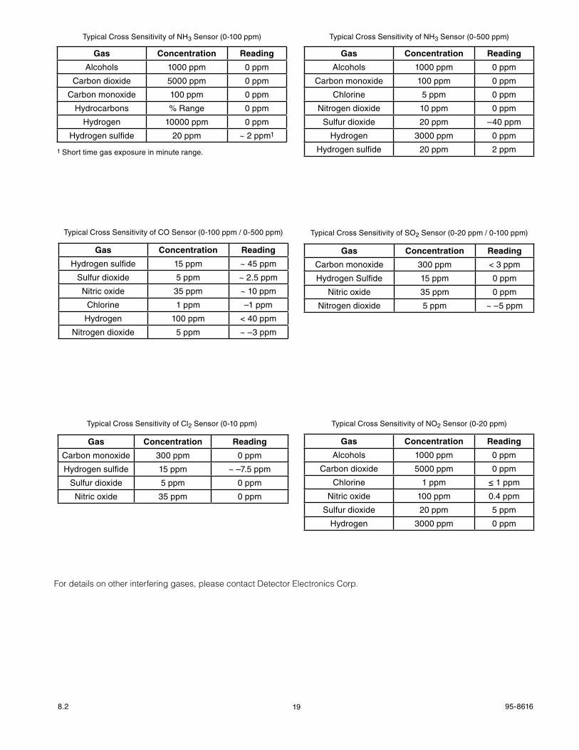
Typical Cross Sensitivity of NH3 Sensor (0-100 ppm)
Gas Concentration Reading
Alcohols 1000 ppm 0 ppm
Carbon dioxide 5000 ppm 0 ppm
Carbon monoxide 100 ppm 0 ppm
Hydrocarbons % Range 0 ppm
Hydrogen 10000 ppm 0 ppm
Hydrogen sulfide 20 ppm ~ 2 ppm1
1 Short time gas exposure in minute range.
Typical Cross Sensitivity of NH3 Sensor (0-500 ppm)
Gas Concentration Reading
Alcohols 1000 ppm 0 ppm
Carbon monoxide 100 ppm 0 ppm
Chlorine 5 ppm 0 ppm
Nitrogen dioxide 10 ppm 0 ppm
Sulfur dioxide 20 ppm –40 ppm
Hydrogen 3000 ppm 0 ppm
Hydrogen sulfide 20 ppm 2 ppm
Typical Cross Sensitivity of CO Sensor (0-100 ppm / 0-500 ppm)
Gas Concentration Reading
Hydrogen sulfide 15 ppm ~ 45 ppm
Sulfur dioxide 5 ppm ~ 2.5 ppm
Nitric oxide 35 ppm ~ 10 ppm
Chlorine 1 ppm –1 ppm
Hydrogen 100 ppm < 40 ppm
Nitrogen dioxide 5 ppm ~ –3 ppm
Typical Cross Sensitivity of NO2 Sensor (0-20 ppm)
Gas Concentration Reading
Alcohols 1000 ppm 0 ppm
Carbon dioxide 5000 ppm 0 ppm
Chlorine 1 ppm ≤ 1 ppm
Nitric oxide 100 ppm 0.4 ppm
Sulfur dioxide 20 ppm 5 ppm
Hydrogen 3000 ppm 0 ppm
Typical Cross Sensitivity of SO2 Sensor (0-20 ppm / 0-100 ppm)
Gas Concentration Reading
Carbon monoxide 300 ppm < 3 ppm
Hydrogen Sulfide 15 ppm 0 ppm
Nitric oxide 35 ppm 0 ppm
Nitrogen dioxide 5 ppm ~ –5 ppm
Typical Cross Sensitivity of Cl2 Sensor (0-10 ppm)
Gas Concentration Reading
Carbon monoxide 300 ppm 0 ppm
Hydrogen sulfide 15 ppm ~ –7.5 ppm
Sulfur dioxide 5 ppm 0 ppm
Nitric oxide 35 ppm 0 ppm
For details on other interfering gases, please contact Detector Electronics Corp.

208.2 95-8616
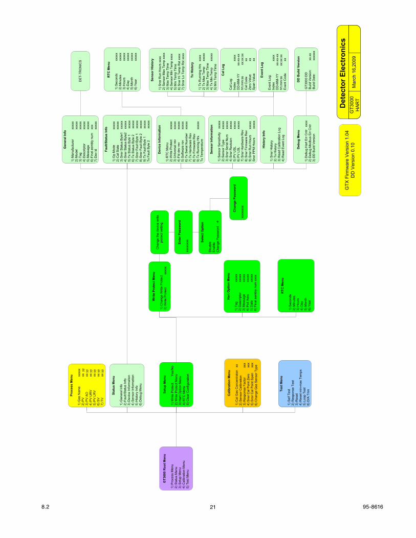
appenDix b
HART COMMUNICATION
Hart menU strUctUre
This section displays the menu tree for the GT3000. The menu tree shows the primary commands and options available when using menu selections of a HART handheld communicator.
218.2 95-8616
Mar
ch 1
6,20
09G
T300
0H
AR
T
Det
ecto
r Ele
ctro
nics
GT3
000
Roo
t Men
u
1) P
roce
ss M
enu
2) S
tatu
s M
enu
3) S
etup
Men
u4)
Cal
ibra
tion
Men
u5)
Tes
t Men
u
Proc
ess
Men
u
1) G
as N
ame
xxxx
x2)
PV
xx y
y3)
PV
AO
xx y
y4)
PV
UR
Vxx
yy
5) P
V L
RV
xx y
y6)
SV
xx y
y7)
TV
xx y
y
Stat
us M
enu
1) G
ener
al In
fo2)
Fau
lt/S
tatu
s In
fo3)
Dev
ice
Info
rmat
ion
4) S
enso
r Inf
orm
atio
n5)
His
tory
Info
6) D
ebug
Men
u
Dev
ice
Info
rmat
ion
1) R
TC M
enu
2) W
rite
Pro
tect
x
xxxx
3) U
nive
rsal
rev
x
xxxx
4) F
ld d
ev re
v
xxx
xx5)
Sof
twar
e re
v
xxx
xx6)
Tx
Ser
ial N
umbe
r
xxxx
x7)
Tx
Har
dwar
e R
ev8)
Tx
Firm
war
e R
ev9)
Tx
Run
ning
Hrs
x
xxxx
Tx T
empe
ratu
re
Sens
or In
form
atio
n
1) S
enso
r Sen
sitiv
ity
xxx
xx2)
Sen
sor T
ype
x
xxxx
3) S
nsr S
eria
l Num
x
xxxx
4) S
nsr R
evis
ion
x
xxxx
5) P
V U
SL
x
xxxx
6) P
V L
SL
xxx
xx7)
Sns
r Har
dwar
e R
ev
8) S
nsr F
irmw
are
Rev
9)
Sns
r Run
Hou
rs
xxx
xxS
nsr P
PM
Hou
rs
xxx
xx
Faul
t/Sta
tus
Info
1) O
p M
ode
x
xxxx
2) C
al S
tate
x
xxxx
3) S
nsr S
tatu
s B
yte1
x
xxxx
4) S
nsr S
tatu
s B
yte2
x
xxxx
5) T
x S
tatu
s B
yte
1
xxx
xx6)
Tx
Sta
tus
Byt
e 2
x
xxxx
7) S
nsr F
ault
Byt
e 1
x
xxxx
8) S
nsr F
ault
Byt
e 2
x
xxxx
9) T
x Fa
ult B
yte
1
xxx
xxTx
Fau
lt By
te 2
x
xxxx
RTC
Men
u
1) S
econ
dsxx
xxx
2) M
inut
esxx
xxx
3) H
ours
xxxx
x4)
Day
xxxx
x5)
Mon
thxx
xxx
6) Y
ear
xxxx
x
His
tory
Info
1) S
nsr H
isto
ry2)
Tx
His
tory
3) R
ead
Cal
ibra
tion
Log
4) R
ead
Eve
nt L
og
Gen
eral
Info
1) M
anuf
actu
rer
x
xxxx
2) M
odel
x
xxxx
3) T
ag
xxx
xx4)
Des
crip
tor
x
xxxx
5) M
essa
ge
xxx
xx6)
Fin
al a
smbl
y nu
m
xxx
7) D
ev id
x
xxxx
Sens
or H
isto
ry
1) S
nsr R
un H
ours
xxx
x2)
Sen
sor M
ax T
emp
xxxx
3) M
ax T
emp
Tim
e4)
Sen
sor M
in T
emp
xxxx
5) M
in T
emp
Tim
e6)
Sns
r Hi T
emp
Rst
xxx
x7)
Sns
r Lo
Tem
p R
st x
xxx
Tx H
isto
ry
1) T
x R
unni
ng H
rs
xxxx
2) T
x M
ax T
emp
xxxx
x3)
Max
Tem
p Ti
me
4) T
x M
in T
emp
xxxx
x5)
Min
Tem
p Ti
me
Cal
Log
Cal
Log
:In
dex
xxxx
DD
-MM
-YY
xx
-xx-
xxhh
:mm
:ss
xx:x
x:xx
Cal
Cod
e
xx
Zero
Val
uexx
Spa
n V
alue
xx
Even
t Log
Eve
nt L
og:
Inde
xxx
xxD
D-M
M-Y
Y
xx-x
x-xx
hh:m
m:s
s
xx:
xx:x
xE
vent
Cod
exx
Deb
ug M
enu
1) D
ebug
Har
t Err
Cnt
r x
xxx
2) D
ebug
Mod
bus
Err
Cnt
r 3)
DD
Bui
ld V
ersi
on
DD
Bui
ld V
ersi
on
GT3
000
DD
Bui
ld V
ersi
on:
xx.x
xB
uild
Dat
e:xx
xxxx
Setu
p M
enu
1) W
rite
Pro
tect
Yes/
No
2) W
rite
Pro
tect
Men
u3)
Har
t Opt
ion
Men
u4)
RTC
Men
u5)
Cle
ar C
onfig
urat
ion
Har
t Opt
ion
Men
u
1) T
agxx
xxx
2) D
escr
ipto
rxx
xxx
3) M
essa
gexx
xxx
4) P
oll A
drs
xxxx
x5)
Dat
exx
xxx
6) F
inal
asm
bly
num
xxx
x
Writ
e Pr
otec
t Men
u
1) C
hang
e W
rite
Pro
tect
2) W
rite
Prot
ect
xxx
xx
RTC
Men
u
1) S
econ
ds2)
Min
utes
3) H
ours
4) D
ay5)
Mon
th6)
Yea
r
Cal
ibra
tion
Men
u
1) C
al G
as C
once
ntra
ton
xx
2) S
enso
r Cal
ibra
tion
3) R
espo
nse
Fact
or
xxx
4) S
nsr C
al P
oint
Zer
o
xx
x5)
Sns
r Cal
Poi
nt S
pan
x
xx6)
Cha
nge
Gas
Sen
sor T
ype
Test
Men
u
1) S
elf T
est
2) R
espo
nse
Test
3) R
eset
4) R
eset
min
-max
Tem
ps5)
Loo
p Te
st6)
D/A
Trim
Ente
r Pas
swor
d
xxxx
xxxx
Sele
ct O
ptio
n
Dis
able
Ena
ble
Cha
nge
Pas
swor
d
Cha
nge
Pass
wor
d
xxxx
xxxx
Cha
nge
the
devi
ce w
rite
prot
ect s
ettin
g.
DE
T-TR
ON
ICS
GTX
Firm
war
e V
ersi
on 1
.04
DD
Ver
sion
0.1
0
228.2 95-8616
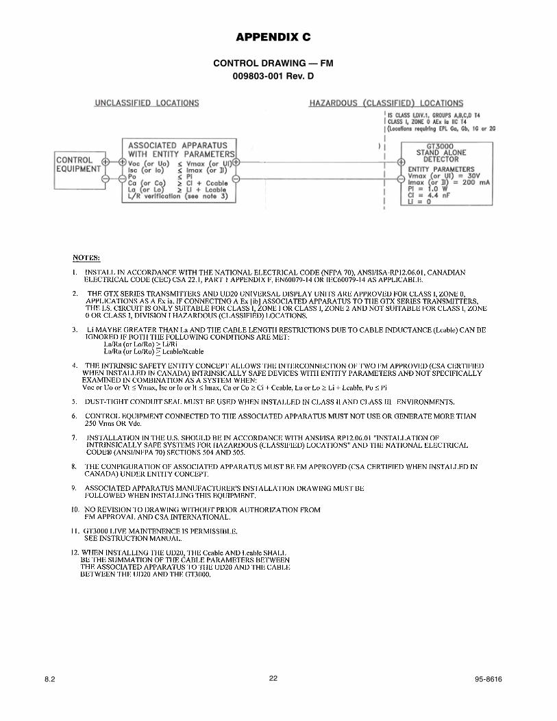
appenDix c
CONTROl DRAWING — FM009803-001 Rev. D
238.2 95-8616
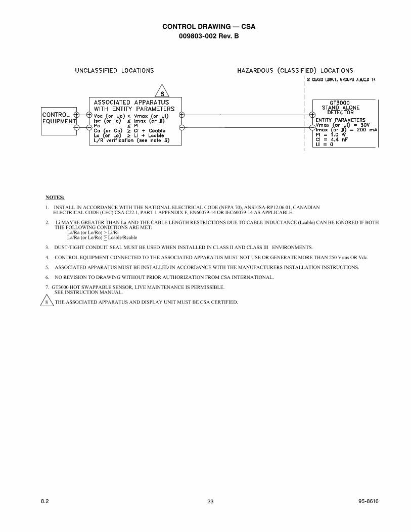
CONTROl DRAWING — CSA009803-002 Rev.b

Detector Electronics Corporation6901 West 110th Street
Minneapolis, MN 55438 USA
T: 952.941.5665 or 800.765.3473F: 952.829.8750
W: http://www.det-tronics.comE: [email protected]
Det-Tronics, the DET-TRONICS logo, Eagle Quantum Premier, Eclipse, and FlexVu are registered trademarks or trademarks of Detector Electronics Corporation in the United States, other countries, or both. Other company, product, or service names may be trademarks or service marks of others.
© Copyright Detector Electronics Corporation 2012. All rights reserved.
95-8616
X3301 Multispectrum IR Flame Detector
PointWatch Eclipse® IR Combustible Gas Detector
Eagle Quantum Premier® Safety System
FlexVu® Universal Displayw/ GT3000 Toxic Gas Detector


![[XLS]xynergy.hkxynergy.hk/attachment/Learning Hub Catalogue_Apr2014.xlsx · Web view92 83 92 62 95 95 83 95 83 62 10 95 10 10 10 10 10 95 97 10 92 10 92 10 95 10 10 95 10 10 95 10](https://img.pdfslide.us/doc/110x75/5a9f35687f8b9a62178c6aa1/xls-hub-catalogueapr2014xlsxweb-view92-83-92-62-95-95-83-95-83-62-10-95-10-10.jpg)