Embed Size (px)
Citation preview
Model: 8600, 8601, 8602, 8610, 8612, 8614, 8616, 8620, 8622, 8624, and 8625
Programmable DC Electronic Loads
USER MANUAL

i
Safety Summary The following safety precautions apply to both operating and maintenance personnel and must
be followed during all phases of operation, service, and repair of this instrument.
Before applying power to this instrument:
Read and understand the safety and operational information in this manual.
Apply all the listed safety precautions.
Verify that the voltage selector at the line power cord input is set to the correct line voltage. Operating the instrument at an incorrect line voltage will void the warranty.
Make all connections to the instrument before applying power.
Do not operate the instrument in ways not specified by this manual or by B&K Precision.
Failure to comply with these precautions or with warnings elsewhere in this manual violates the
safety standards of design, manufacture, and intended use of the instrument. B&K Precision
assumes no liability for a customer’s failure to comply with these requirements.
Category rating
The IEC 61010 standard defines safety category ratings that specify the amount of electrical
energy available and the voltage impulses that may occur on electrical conductors associated
with these category ratings. The category rating is a Roman numeral of I, II, III, or IV. This rating
is also accompanied by a maximum voltage of the circuit to be tested, which defines the voltage
impulses expected and required insulation clearances. These categories are:
Category I (CAT I): Measurement instruments whose measurement inputs are not intended to
be connected to the mains supply. The voltages in the environment are typically derived from a
limited-energy transformer or a battery.
Category II (CAT II): Measurement instruments whose measurement inputs are meant to be
connected to the mains supply at a standard wall outlet or similar sources. Example
measurement environments are portable tools and household appliances.
Category III (CAT III): Measurement instruments whose measurement inputs are meant to be
connected to the mains installation of a building. Examples are measurements inside a
building's circuit breaker panel or the wiring of permanently-installed motors.
ii
Category IV (CAT IV): Measurement instruments whose measurement inputs are meant to be
connected to the primary power entering a building or other outdoor wiring.
Do not use this instrument in an electrical environment with a higher category rating than what
is specified in this manual for this instrument.
You must ensure that each accessory you use with this instrument has a category rating equal
to or higher than the instrument's category rating to maintain the instrument's category rating.
Failure to do so will lower the category rating of the measuring system.
Electrical Power
This instrument is intended to be powered from a CATEGORY II mains power environment. The
mains power should be 120 V RMS or 240 V RMS. Use only the power cord supplied with the
instrument and ensure it is appropriate for your country of use.
Ground the Instrument
To minimize shock hazard, the instrument chassis and cabinet must be connected to an
electrical safety ground. This instrument is grounded through the ground conductor of the
supplied, three-conductor AC line power cable. The power cable must be plugged into an
approved three-conductor electrical outlet. The power jack and mating plug of the power cable
meet IEC safety standards.
Do not alter or defeat the ground connection. Without the safety ground connection, all
accessible conductive parts (including control knobs) may provide an electric shock. Failure to
use a properly-grounded approved outlet and the recommended three-conductor AC line
power cable may result in injury or death.
Unless otherwise stated, a ground connection on the instrument's front or rear panel is for a
reference of potential only and is not to be used as a safety ground.
iii
Do not operate in an explosive or flammable atmosphere
Do not operate the instrument in the presence of flammable gases or vapors, fumes, or finely-
divided particulates.
The instrument is designed to be used in office-type indoor environments. Do not operate the
instrument
In the presence of noxious, corrosive, or flammable fumes, gases, vapors, chemicals, or finely-divided particulates.
In relative humidity conditions outside the instrument's specifications.
In environments where there is a danger of any liquid being spilled on the instrument or where any liquid can condense on the instrument.
In air temperatures exceeding the specified operating temperatures.
In atmospheric pressures outside the specified altitude limits or where the surrounding gas is not air.
In environments with restricted cooling air flow, even if the air temperatures are within specifications.
In direct sunlight.
This instrument is intended to be used in an indoor pollution degree 2 environment. The
operating temperature range is 0 °C to 40 °C and the operating humidity range is ≤ 95% relative
humidity with no condensation allowed.
Measurements made by this instrument may be outside specifications if the instrument is used
in non-office-type environments. Such environments may include rapid temperature or
humidity changes, sunlight, vibration and/or mechanical shocks, acoustic noise, electrical noise,
strong electric fields, or strong magnetic fields.
Do not operate instrument if damaged
If the instrument is damaged, appears to be damaged, or if any liquid,
chemical, or other material gets on or inside the instrument, remove the instrument's power
iv
cord, remove the instrument from service, label it as not to be operated, and return the
instrument to B&K Precision for repair. Notify B&K Precision of the nature of any contamination
of the instrument.
Clean the instrument only as instructed
Do not clean the instrument, its switches, or its terminals with contact cleaners, abrasives,
lubricants, solvents, acids/bases, or other such chemicals. Clean the instrument only with a
clean dry lint-free cloth or as instructed in this manual.
Not for critical applications
This instrument is not authorized for use in contact with the human body or for use as a
component in a life-support device or system.
Do not touch live circuits
Instrument covers must not be removed by operating personnel. Component replacement and
internal adjustments must be made by qualified service-trained maintenance personnel who
are aware of the hazards involved when the instrument's covers and shields are removed.
Under certain conditions, even with the power cord removed, dangerous voltages may exist
when the covers are removed. To avoid injuries, always disconnect the power cord from the
instrument, disconnect all other connections (for example, test leads, computer interface
cables, etc.), discharge all circuits, and verify there are no hazardous voltages present on any
conductors by measurements with a properly-operating voltage-sensing device before touching
any internal parts. Verify the voltage-sensing device is working properly before and after
making the measurements by testing with known-operating voltage sources and test for both
DC and AC voltages. Do not attempt any service or adjustment unless another person capable of
rendering first aid and resuscitation is present.
Do not insert any object into an instrument's ventilation openings or other openings.
v
Hazardous voltages may be present in unexpected locations in circuitry being tested when a
fault condition in the circuit exists.
Fuse replacement
Fuse replacement must be done by qualified service-trained maintenance personnel who are
aware of the instrument's fuse requirements and safe replacement procedures. Disconnect the
instrument from the power line before replacing fuses. Replace fuses only with new fuses of
the fuse types, voltage ratings, and current ratings specified in this manual or on the back of the
instrument. Failure to do so may damage the instrument, lead to a safety hazard, or cause a fire.
Failure to use the specified fuses will void the warranty.
Servicing
Do not substitute parts that are not approved by B&K Precision or modify this instrument.
Return the instrument to B&K Precision for service and repair to ensure that safety and
performance features are maintained.
Cooling fans
This instrument contains one or more cooling fans. For continued safe operation of the
instrument, the air inlet and exhaust openings for these fans must not be blocked nor must
accumulated dust or other debris be allowed to reduce air flow. Maintain at least 25 mm
clearance around the sides of the instrument that contain air inlet and exhaust ports. If
mounted in a rack, position power devices in the rack above the instrument to minimize
instrument heating while rack mounted. Do not continue to operate the instrument if you
cannot verify the fan is operating (note some fans may have intermittent duty cycles). Do not
insert any object into the fan's inlet or outlet.
vi
Do not short-circuit batteries
When using a DC load to discharge a battery, do not exceed the battery manufacturer's
specified maximum rate of discharge.
Use correctly sized wires
To connect the load to the power supply, use a wire diameter large enough to handle the
maximum continuous output short-circuit current of the power supply without the wire
overheating.
For continued safe use of the instrument
Do not place heavy objects on the instrument.
Do not obstruct cooling air flow to the instrument.
Do not place a hot soldering iron on the instrument.
Do not pull the instrument with the power cord, connected probe, or connected test lead.
Do not move the instrument when a probe is connected to a circuit being tested.
vii
Compliance Statements Disposal of Old Electrical & Electronic Equipment (Applicable in the European Union and
other European countries with separate collection systems)
This product is subject to Directive 2002/96/EC of the
European Parliament and the Council of the European Union
on waste electrical and electronic equipment (WEEE) , and
in jurisdictions adopting that Directive, is marked as being
put on the market after August 13, 2005, and should not be
disposed of as unsorted municipal waste. Please utilize your
local WEEE collection facilities in the disposition of this
product and otherwise observe all applicable requirements.
viii
CE Declaration of Conformity The instrument meets the requirements of 2006/95/EC Low Voltage Directive and 2004/108/EC Electromagnetic Compatibility Directive with the following standards. Low Voltage Directive
- EN61010-1: 2001 EMC Directive
- EN 61000-3-2: 2006 - EN 61000-3-3: 1995+A1: 2001+A2: 2005 - EN 61000-4-2 / -3 / -4 / -5 / -6 / -11 - EN 61326-1: 2006
ix
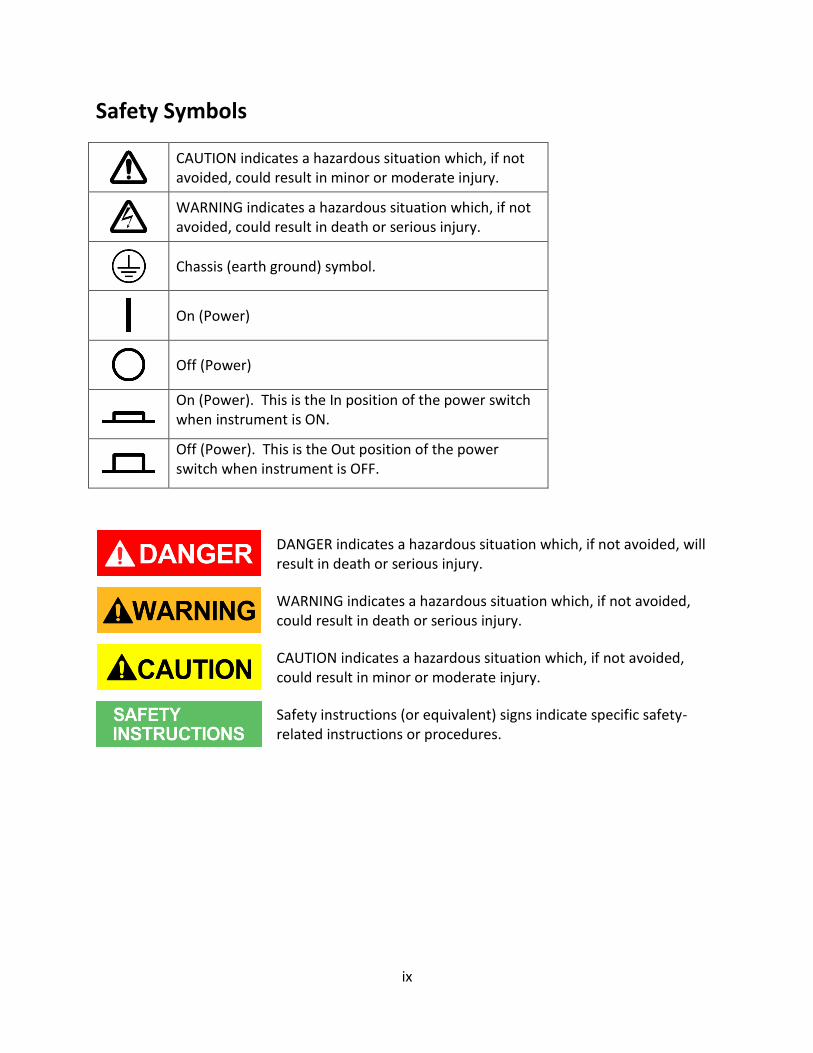
Safety Symbols
CAUTION indicates a hazardous situation which, if not avoided, could result in minor or moderate injury.
WARNING indicates a hazardous situation which, if not avoided, could result in death or serious injury.
Chassis (earth ground) symbol.
On (Power)
Off (Power)
On (Power). This is the In position of the power switch when instrument is ON.
Off (Power). This is the Out position of the power switch when instrument is OFF.
DANGER indicates a hazardous situation which, if not avoided, will result in death or serious injury.
WARNING indicates a hazardous situation which, if not avoided, could result in death or serious injury.
CAUTION indicates a hazardous situation which, if not avoided, could result in minor or moderate injury.
Safety instructions (or equivalent) signs indicate specific safety-related instructions or procedures.
x
Table of Contents Safety Summary ................................................................................................... i
Compliance Statements ............................................................................................................. vii
CE Declaration of Conformity.................................................................................................... viii
1 General Information ..................................................................................... 1
1.1 Product Overview ........................................................................................................... 1
1.2 Package Contents ............................................................................................................ 2
1.3 Product Dimensions ........................................................................................................ 2
1.4 Rackmount Installation ................................................................................................... 6
1.5 Front Panel Overview ...................................................................................................... 7
Front Panel Description ........................................................................................................... 8
1.6 Rear Panel Overview ....................................................................................................... 9
Rear Panel Description .......................................................................................................... 10
1.7 Display Overview ........................................................................................................... 10
Display Description ................................................................................................................ 11
2 Getting Started ........................................................................................... 12
2.1 Input Power and Fuse Requirements ............................................................................ 12
Input Power ........................................................................................................................... 12
Fuse Requirements ................................................................................................................ 13
Fuse Replacement ................................................................................................................. 13
2.2 Input Connections ......................................................................................................... 14
2.3 Preliminary Check ......................................................................................................... 15
Self-test Errors ....................................................................................................................... 15
Input Check ............................................................................................................................ 16
Check Model and Firmware Version ..................................................................................... 17
3 Front Panel Operation ................................................................................ 18
3.1 Menu Options ............................................................................................................... 18
System Menu ......................................................................................................................... 18
Config Menu .......................................................................................................................... 18
How to Navigate the Menu ................................................................................................... 19
3.2 Configure Operation Modes (CC/CV/CR/CW) ............................................................... 20
xi
Constant Current (CC) Mode ................................................................................................. 20
Constant Voltage (CV) Mode ................................................................................................. 23
Constant Resistance (CR) Mode ............................................................................................ 24
Constant Power (CW) Mode .................................................................................................. 25
Setting CC, CV, CR, CW Mode ................................................................................................ 27
3.3 SYSTEM Menu ............................................................................................................... 27
Restore Factory Default Settings ........................................................................................... 28
Configure Power-On State ..................................................................................................... 29
Load On Knob ........................................................................................................................ 29
Configure Trigger Source ....................................................................................................... 30
Save/Recall Instrument Settings ........................................................................................... 31
Display Input On Timer .......................................................................................................... 34
Remote Interface Setup ......................................................................................................... 34
3.4 CONFIG Menu ............................................................................................................... 37
Von Operation ....................................................................................................................... 37
Configure Protection Settings ............................................................................................... 40
Configure Timed Input .......................................................................................................... 44
Measurement Configurations ............................................................................................... 44
CR LED Function .................................................................................................................... 46
Remote Sense ........................................................................................................................ 47
External Analog Control and Monitor ................................................................................... 48
3.5 Short Operation ............................................................................................................ 50
3.6 Transient Operation ...................................................................................................... 51
Continuous ............................................................................................................................ 51
Pulse ...................................................................................................................................... 52
Toggle .................................................................................................................................... 52
3.7 List Operation ................................................................................................................ 56
Configure List ........................................................................................................................ 57
Run List .................................................................................................................................. 59
3.8 Battery Test Function .................................................................................................... 60
3.9 Test Operations ............................................................................................................. 61
Automatic Test Function ........................................................................................................ 61
OCP Test Function .................................................................................................................. 71
xii
OPP Test Function .................................................................................................................. 74
3.10 Key Lock......................................................................................................................... 77
4 Remote Operation ...................................................................................... 78
4.1 Interface Connection..................................................................................................... 78
RS-232 ................................................................................................................................... 78
GPIB ....................................................................................................................................... 79
USBTMC ................................................................................................................................. 79
4.2 Remote Commands ....................................................................................................... 79
5 Troubleshooting Guide ............................................................................... 80
General .................................................................................................................................. 80
Remote Control ..................................................................................................................... 80
6 Specifications ............................................................................................. 81
Supplementary Characteristics ................................................................................................. 87
7 Calibration .................................................................................................. 89
Index ................................................................................................................. 90
1
1 General Information
1.1 Product Overview
The 8600 Series DC Electronic Loads are versatile instruments used for static and dynamic
testing of DC power supplies, batteries, DC-to-DC converters, and battery chargers. Other
applications include fuel-cell and photovoltaic cell test.
The DC load can be used in one of the following operation modes: constant voltage (CV),
constant current (CC), constant resistance (CR), or constant power (CW). A wide range of
dynamic loading applications can be simulated through user-programmable slew rates, load
levels, duration, and conducting voltage. The DC load can be remotely programmed via the USB,
GPIB, or RS-232 serial interface. Versatile triggering options allow the dynamic load behavior to
be synchronized with other events.
A battery test mode is provided that will measure the ampere-hour (Ah) characteristic of a
battery. Shorts can be simulated by either the front panel or custom programming. The DC
source or other components can be protected from excessive voltage, current, or power, which
will cause the DC load to shut down if excessive levels or reverse polarity are detected.
Features:
CC/CV/CR/CW operating modes
High Resolution Display
Transient mode up to 25 kHz
List mode function
Measurement speed up to 50 kHz
Remote sense function
Built-in battery test function
OCP and OPP auto test function
CR-LED function
Store/recall up to 100 setups
RS232/USBTMC/GPIB interfaces
Analog current control and monitoring
Adjustable slew rate in CC mode
OVP/OCP/OPP/OTP and reverse voltage protection
2
1.2 Package Contents
Please inspect the instrument mechanically and electrically upon receiving it. Unpack all items
from the shipping carton, and check for any obvious signs of physical damage that may have
occurred during transportation. Report any damage to the shipping agent immediately. Save
the original packing carton for possible future reshipment. Every instrument is shipped with the
following contents:
1x 8600 series DC Electronic load
1x User Manual
1x AC Power Cord
Certificate of Calibration
Test Report
Verify that all items above are included in the shipping container. If anything is missing, please
contact B&K Precision.
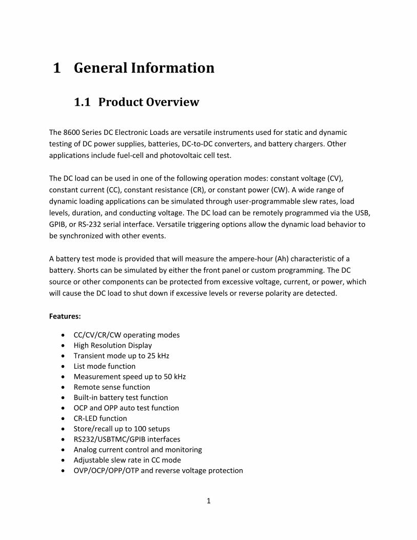
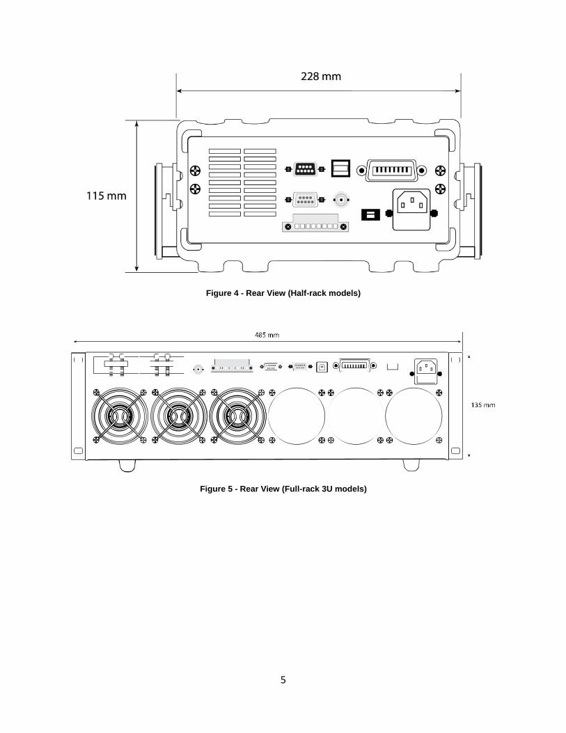
1.3 Product Dimensions
All models are designed to fit in a standard 19-inch rackmount. The dimensions are shown in
Figure 1 below.
3
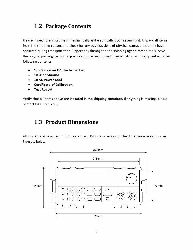
Figure 1 – Front and Side View (Half-rack models)
Figure 2 - Front and Side View (Full-rack 3U models)
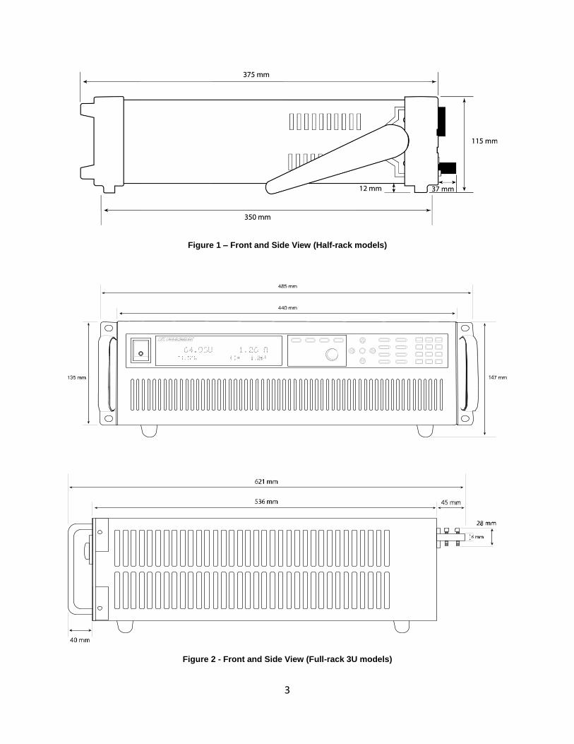
4
Figure 3 Front and Side View (Full-rack 6U models)
5
Figure 4 - Rear View (Half-rack models)
Figure 5 - Rear View (Full-rack 3U models)
6
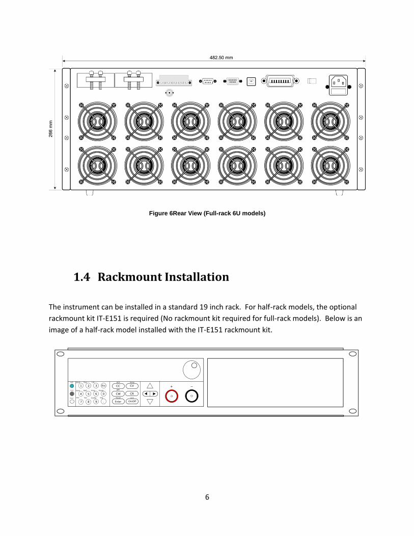
1.4 Rackmount Installation
The instrument can be installed in a standard 19 inch rack. For half-rack models, the optional
rackmount kit IT-E151 is required (No rackmount kit required for full-rack models). Below is an
image of a half-rack model installed with the IT-E151 rackmount kit.
Figure 6Rear View (Full-rack 6U models)
7
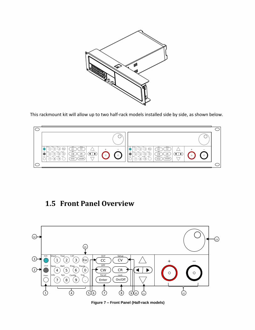
This rackmount kit will allow up to two half-rack models installed side by side, as shown below.
1.5 Front Panel Overview
1
2
3
4 5 6 7 9 10 12
14
8
13
11
15
Figure 7 – Front Panel (Half-rack models)
8
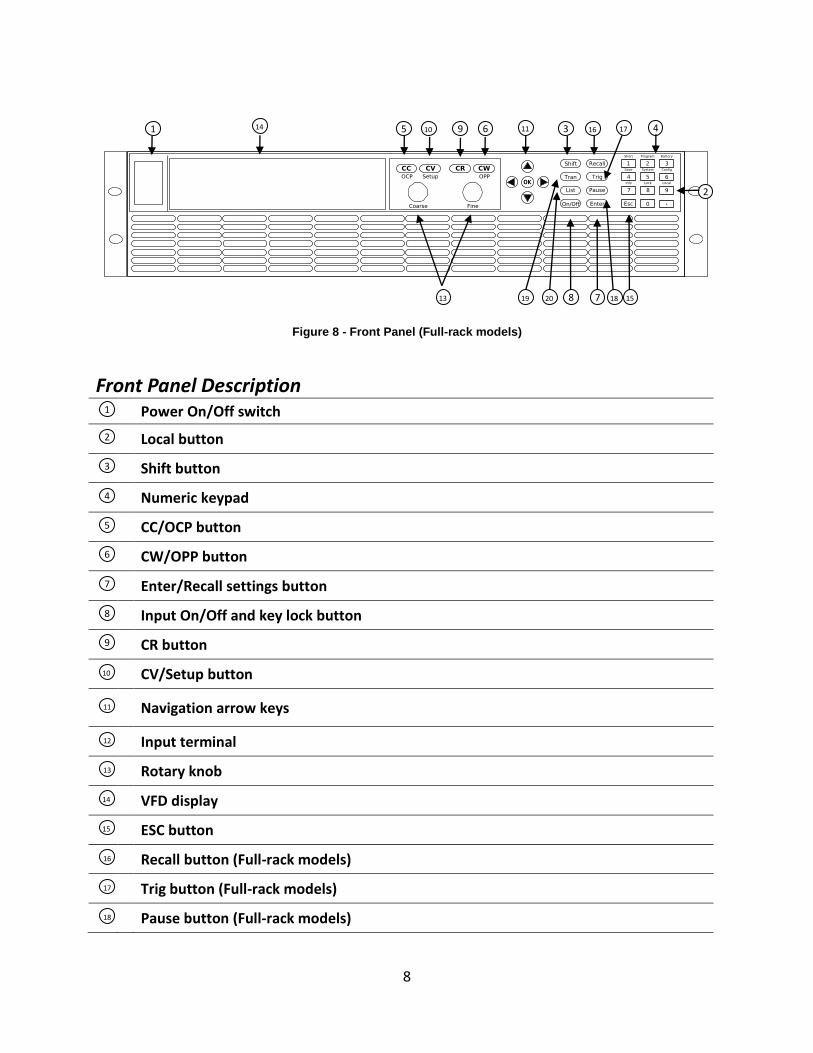
Front Panel Description Power On/Off switch
Local button
Shift button
Numeric keypad
CC/OCP button
CW/OPP button
Enter/Recall settings button
Input On/Off and key lock button
CR button
CV/Setup button
Navigation arrow keys
Input terminal
Rotary knob
VFD display
ESC button
Recall button (Full-rack models)
Trig button (Full-rack models)
Pause button (Full-rack models)
1 11 4 5 6
7
9 10
8 15
3
13
14
2
16 17
18 19 20
1
2
3
4
5
6
7
8
14
12
13
9
10
11
15
16
Figure 8 - Front Panel (Full-rack models)
17
18
9
Trans button (Full-rack models)
List button (Full-rack models)
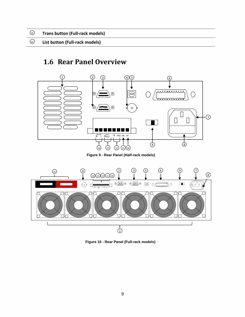
1.6 Rear Panel Overview
1
2 3 4 5 6 9 8
7 10 11 12 13 14
15
1 2 3
9
4 5 6
7
8 10
11 12 13 14
Figure 9 - Rear Panel (Half-rack models)
Figure 10 - Rear Panel (Full-rack models)
19
20
10
Rear Panel Description Cooling fan vent
Remote control port (not used)
RS232 Interface
Current Monitor BNC output
USB Interface
GPIB Interface
AC input receptacle
Fuse box
Line voltage selector
Voltage fault (VF) output terminal
Input On/Off (ON) control terminal
External trigger input terminals
External programming input terminals
Remote sense terminals
Input Terminal (Full-rack models)
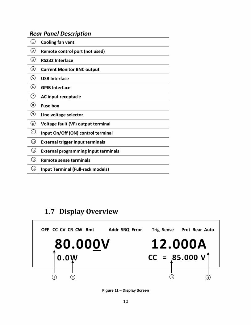
1.7 Display Overview
Figure 11 – Display Screen
80.000V 12.000A 0.0W
OFF CC CV CR CW Rmt Addr SRQ Error Trig Sense Prot Rear Auto
* Shift
CC = 85.000 V
1 2 3 4
1
2
3
4
5
6
7
8
9
10
11
12
13
14
15
11
Display Description Measured input voltage
Measured input power
Settings Display Displays parameter settings such as CC, CV, CR, CW
Measured input current
OFF Indicates input is disabled
CC Indicates constant current (CC) operation
CV Indicates constant voltage (CV) operation
CR Indicates constant resistance (CR) operation
CW Indicates constant power (CW) operation
Rmt Indicates remote mode
Addr Indicates remote communication activity
SRQ SRQ service request indicator
Error Indicates an error has occurred
Trig Indicates waiting for trigger
Sense Indicates remote sense enabled
Prot Indicates protection trip for over voltage, over power, or over current
Rear Indicates external analog control is enabled.
Auto Indicates voltage auto range is enabled.
* Indicates key lock is enabled
Shift Indicates shift mode (for access to secondary button functions)
1
2
3
4
12
2 Getting Started
Before connecting and powering up the instrument, please review and go through the
instructions in this chapter.
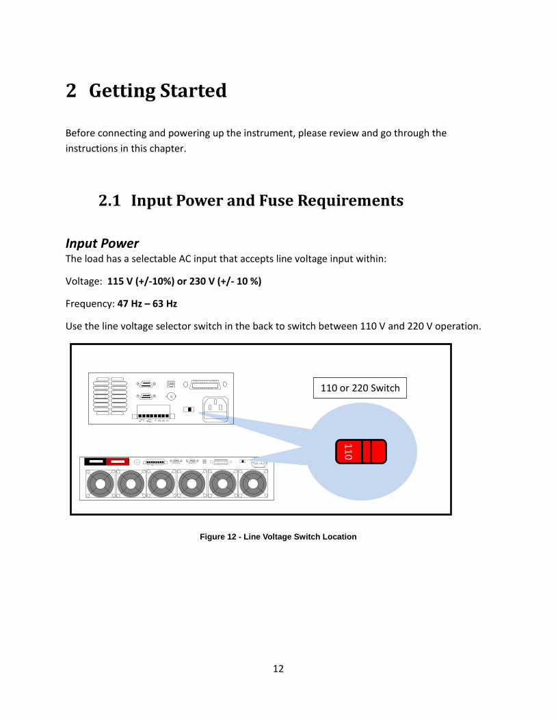
2.1 Input Power and Fuse Requirements
Input Power The load has a selectable AC input that accepts line voltage input within:
Voltage: 115 V (+/-10%) or 230 V (+/- 10 %)
Frequency: 47 Hz – 63 Hz
Use the line voltage selector switch in the back to switch between 110 V and 220 V operation.
Figure 12 - Line Voltage Switch Location
110 or 220 Switch
11
0
13
Disconnect all cables including the power cord from the instrument when changing the
instrument's line voltage. After changing the line voltage setting, ensure the instrument has
fuses of the proper ratings and types for the selected line voltage before applying line power.
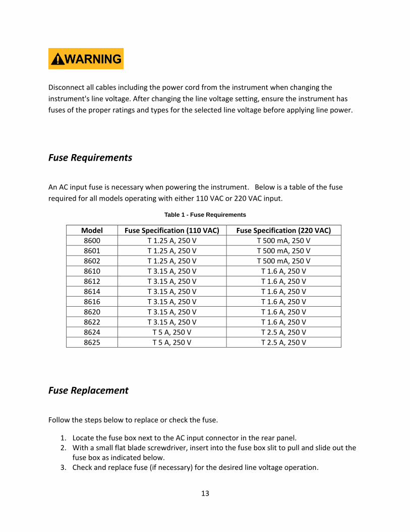
Fuse Requirements
An AC input fuse is necessary when powering the instrument. Below is a table of the fuse
required for all models operating with either 110 VAC or 220 VAC input.
Table 1 - Fuse Requirements
Model Fuse Specification (110 VAC) Fuse Specification (220 VAC)
8600 T 1.25 A, 250 V T 500 mA, 250 V
8601 T 1.25 A, 250 V T 500 mA, 250 V
8602 T 1.25 A, 250 V T 500 mA, 250 V
8610 T 3.15 A, 250 V T 1.6 A, 250 V
8612 T 3.15 A, 250 V T 1.6 A, 250 V
8614 T 3.15 A, 250 V T 1.6 A, 250 V
8616 T 3.15 A, 250 V T 1.6 A, 250 V
8620 T 3.15 A, 250 V T 1.6 A, 250 V
8622 T 3.15 A, 250 V T 1.6 A, 250 V
8624 T 5 A, 250 V T 2.5 A, 250 V
8625 T 5 A, 250 V T 2.5 A, 250 V
Fuse Replacement
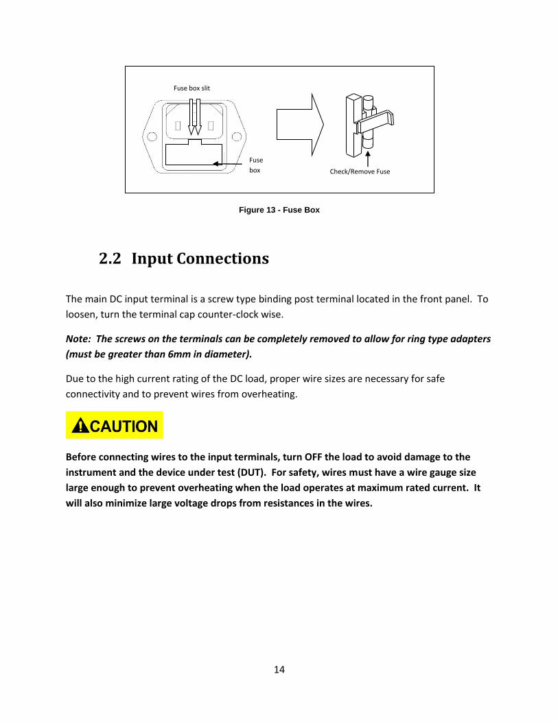
Follow the steps below to replace or check the fuse.
1. Locate the fuse box next to the AC input connector in the rear panel. 2. With a small flat blade screwdriver, insert into the fuse box slit to pull and slide out the
fuse box as indicated below. 3. Check and replace fuse (if necessary) for the desired line voltage operation.
14
Figure 13 - Fuse Box
2.2 Input Connections
The main DC input terminal is a screw type binding post terminal located in the front panel. To
loosen, turn the terminal cap counter-clock wise.
Note: The screws on the terminals can be completely removed to allow for ring type adapters
(must be greater than 6mm in diameter).
Due to the high current rating of the DC load, proper wire sizes are necessary for safe
connectivity and to prevent wires from overheating.
Before connecting wires to the input terminals, turn OFF the load to avoid damage to the
instrument and the device under test (DUT). For safety, wires must have a wire gauge size
large enough to prevent overheating when the load operates at maximum rated current. It
will also minimize large voltage drops from resistances in the wires.
Fuse box slit
Fuse
box Check/Remove Fuse
15
2.3 Preliminary Check
Complete the following steps to verify that the load is ready for use.
1. Verify AC Input Voltage Verify and check to make sure proper AC voltages are available to power the instrument. The AC voltage range must meet the acceptable specification as explained in “2.1 Input Power and Fuse Requirements”.
Check to verify that the unit is configured to operate at the AC input voltage level of the power source. If not, it will damage the unit and void its warranty.
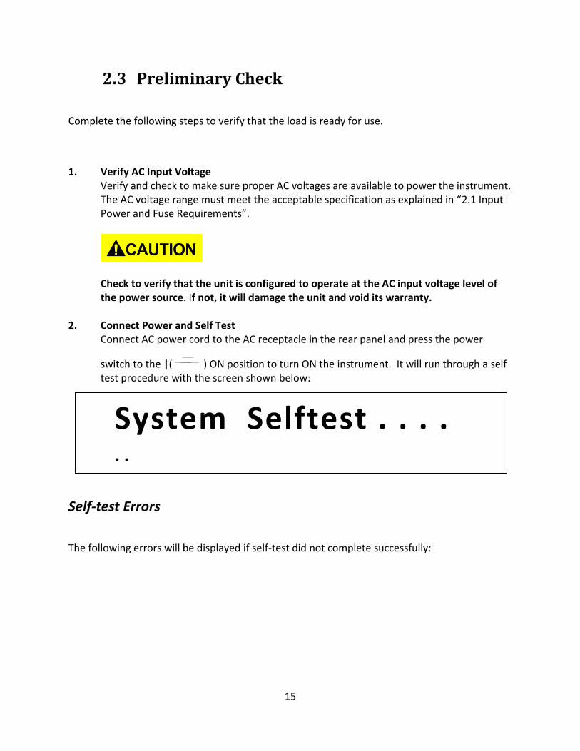
2. Connect Power and Self Test Connect AC power cord to the AC receptacle in the rear panel and press the power
switch to the |( ) ON position to turn ON the instrument. It will run through a self test procedure with the screen shown below:
Self-test Errors
The following errors will be displayed if self-test did not complete successfully:
System Selftest . . . . . .
16
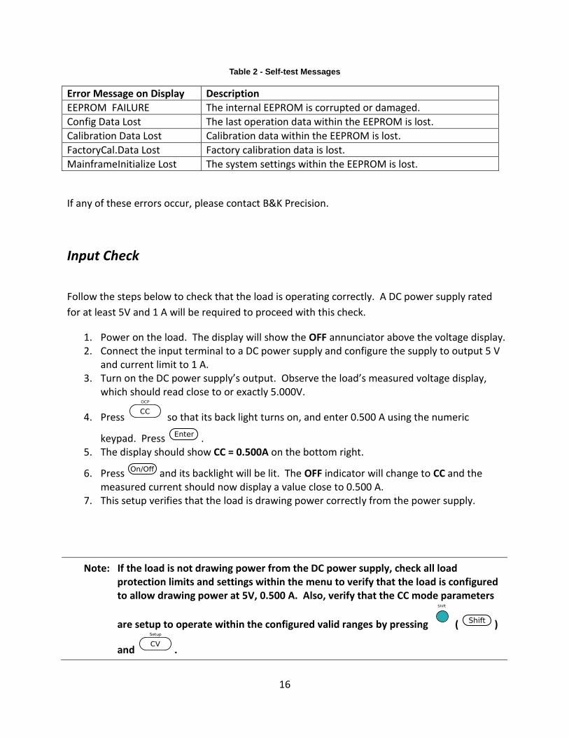
Table 2 - Self-test Messages
Error Message on Display Description
EEPROM FAILURE The internal EEPROM is corrupted or damaged.
Config Data Lost The last operation data within the EEPROM is lost.
Calibration Data Lost Calibration data within the EEPROM is lost.
FactoryCal.Data Lost Factory calibration data is lost.
MainframeInitialize Lost The system settings within the EEPROM is lost.
If any of these errors occur, please contact B&K Precision.
Input Check
Follow the steps below to check that the load is operating correctly. A DC power supply rated
for at least 5V and 1 A will be required to proceed with this check.
1. Power on the load. The display will show the OFF annunciator above the voltage display. 2. Connect the input terminal to a DC power supply and configure the supply to output 5 V
and current limit to 1 A. 3. Turn on the DC power supply’s output. Observe the load’s measured voltage display,
which should read close to or exactly 5.000V.
4. Press so that its back light turns on, and enter 0.500 A using the numeric
keypad. Press . 5. The display should show CC = 0.500A on the bottom right.
6. Press and its backlight will be lit. The OFF indicator will change to CC and the measured current should now display a value close to 0.500 A.
7. This setup verifies that the load is drawing power correctly from the power supply.
Note: If the load is not drawing power from the DC power supply, check all load protection limits and settings within the menu to verify that the load is configured to allow drawing power at 5V, 0.500 A. Also, verify that the CC mode parameters
are setup to operate within the configured valid ranges by pressing ( )
and .
17
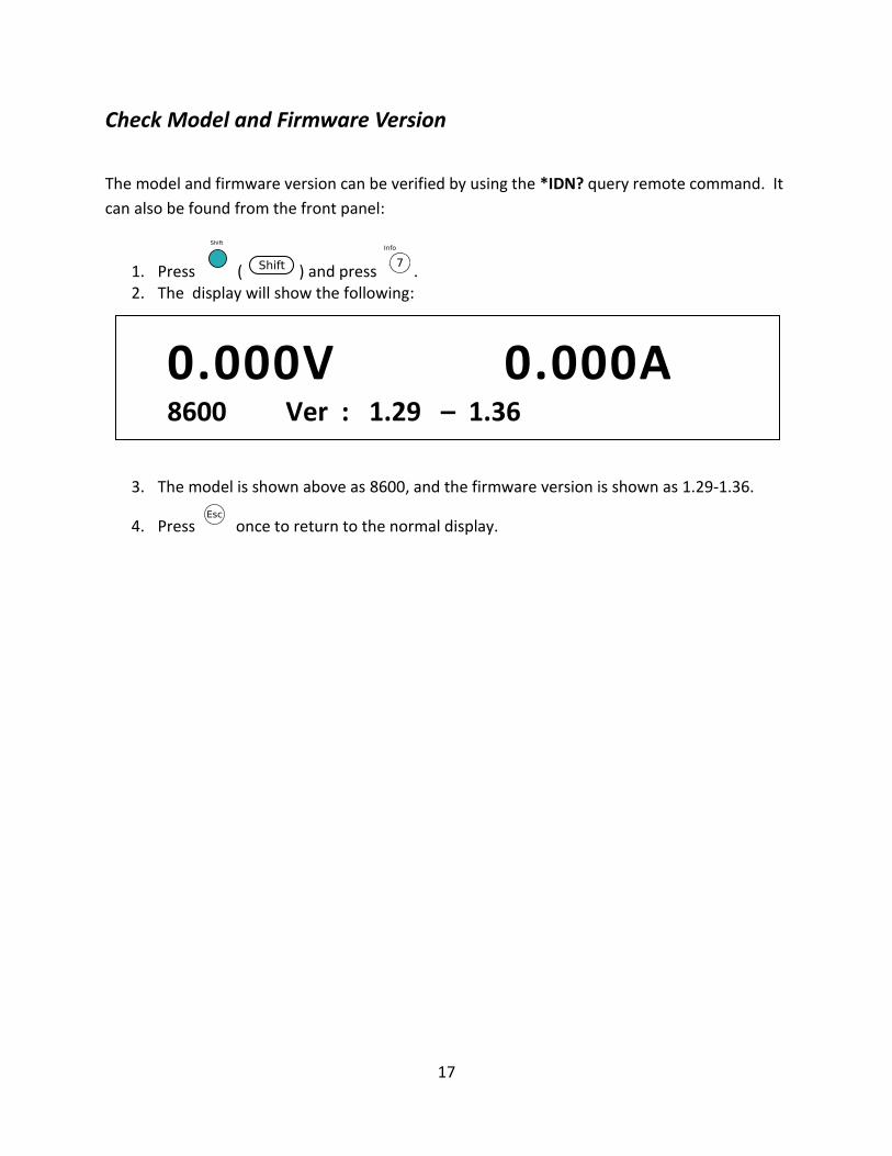
Check Model and Firmware Version
The model and firmware version can be verified by using the *IDN? query remote command. It
can also be found from the front panel:
1. Press ( ) and press . 2. The display will show the following:
3. The model is shown above as 8600, and the firmware version is shown as 1.29-1.36.
4. Press once to return to the normal display.
8600 Ver : 1.29 – 1.36
0.000A 0.000V
18
3 Front Panel Operation
3.1 Menu Options
Most settings and parameters can be configured from the built-in menu systems of the
instrument. There are two main menus: System and Config.
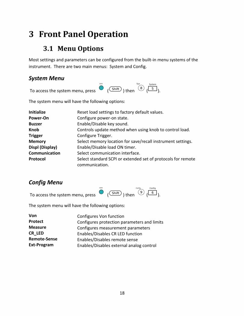
System Menu
To access the system menu, press ( ) then ( ).
The system menu will have the following options:
Initialize Reset load settings to factory default values. Power-On Configure power-on state. Buzzer Enable/Disable key sound. Knob Controls update method when using knob to control load. Trigger Configure Trigger. Memory Select memory location for save/recall instrument settings. Displ (Display) Enable/Disable load ON timer. Communication Select communication interface. Protocol Select standard SCPI or extended set of protocols for remote
communication.
Config Menu
To access the system menu, press ( ) then ( ).
The system menu will have the following options:
Von Configures Von function Protect Configures protection parameters and limits Measure Configures measurement parameters CR_LED Enables/Disables CR LED function Remote-Sense Enables/Disables remote sense Ext-Program Enables/Disables external analog control
19
How to Navigate the Menu Before using the instrument, it is important to be familiarized with its menu structure and learn
how to view or change settings and parameters. Follow the steps below to guide you in
selecting menu options.
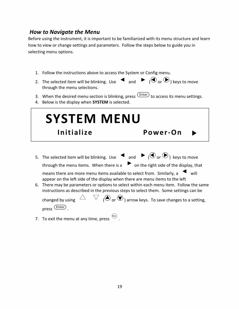
1. Follow the instructions above to access the System or Config menu.
2. The selected item will be blinking. Use and ( or ) keys to move through the menu selections.
3. When the desired menu section is blinking, press to access its menu settings. 4. Below is the display when SYSTEM is selected.
5. The selected item will be blinking. Use and ( or ) keys to move
through the menu items. When there is a on the right side of the display, that
means there are more menu items available to select from. Similarly, a will appear on the left side of the display when there are menu items to the left
6. There may be parameters or options to select within each menu item. Follow the same instructions as described in the previous steps to select them. Some settings can be
changed by using ( or ) arrow keys. To save changes to a setting,
press .
7. To exit the menu at any time, press .
SYSTEM MENU In it ial ize Power-On
20
3.2 Configure Operation Modes (CC/CV/CR/CW)
The electronic load can work in the following modes:
1) Constant current (CC) operation mode
2) Constant voltage (CV) operation mode
3) Constant resistance (CR) operation mode
4) Constant power (CW) operation mode
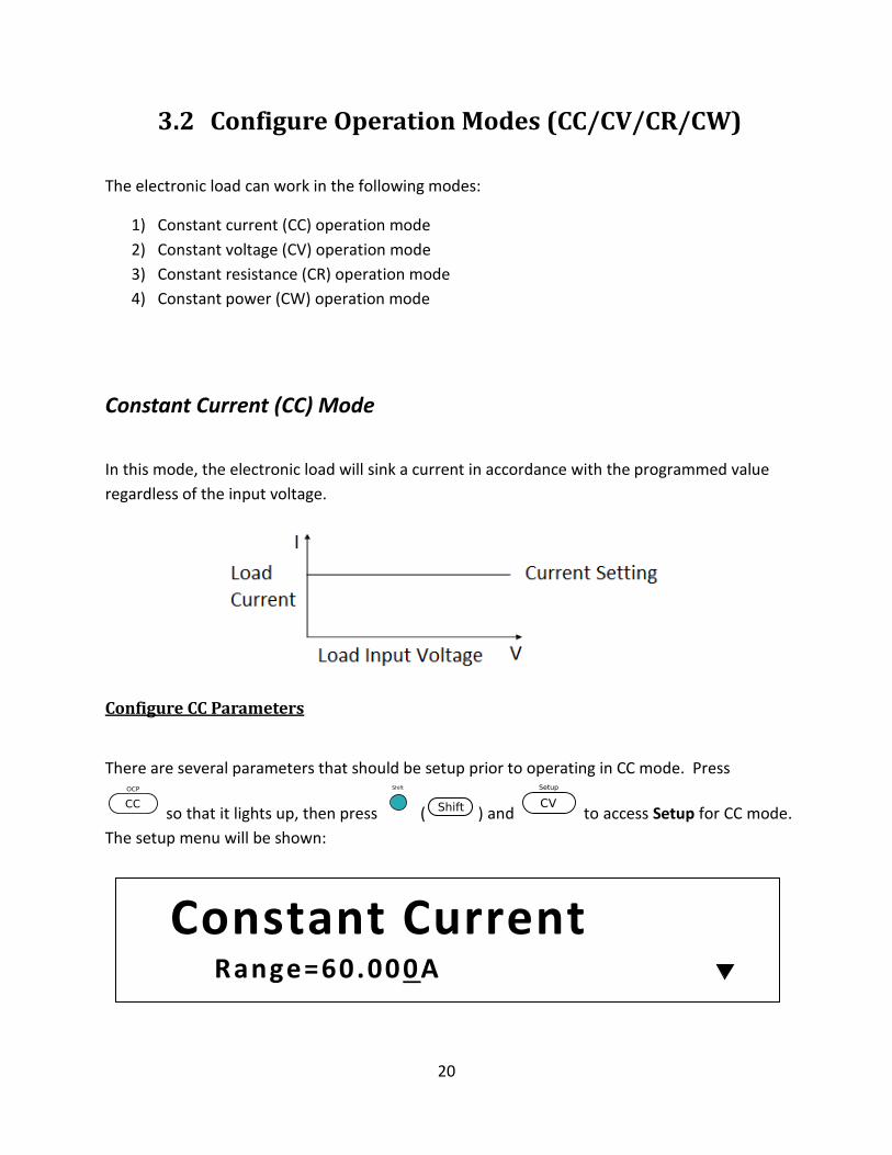
Constant Current (CC) Mode
In this mode, the electronic load will sink a current in accordance with the programmed value
regardless of the input voltage.
Configure CC Parameters
There are several parameters that should be setup prior to operating in CC mode. Press
so that it lights up, then press ( ) and to access Setup for CC mode.
The setup menu will be shown:
Constant Current Range=60.000A
21
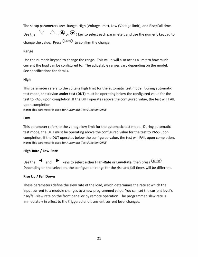
The setup parameters are: Range, High (Voltage limit), Low (Voltage limit), and Rise/Fall time.
Use the ( or ) key to select each parameter, and use the numeric keypad to
change the value. Press to confirm the change.
Range
Use the numeric keypad to change the range. This value will also act as a limit to how much
current the load can be configured to. The adjustable ranges vary depending on the model.
See specifications for details.
High
This parameter refers to the voltage high limit for the automatic test mode. During automatic
test mode, the device under test (DUT) must be operating below the configured value for the
test to PASS upon completion. If the DUT operates above the configured value, the test will FAIL
upon completion. Note: This parameter is used for Automatic Test Function ONLY.
Low
This parameter refers to the voltage low limit for the automatic test mode. During automatic
test mode, the DUT must be operating above the configured value for the test to PASS upon
completion. If the DUT operates below the configured value, the test will FAIL upon completion. Note: This parameter is used for Automatic Test Function ONLY.
High-Rate / Low-Rate
Use the and keys to select either High-Rate or Low-Rate, then press .
Depending on the selection, the configurable range for the rise and fall times will be different.
Rise Up / Fall Down
These parameters define the slew rate of the load, which determines the rate at which the
input current to a module changes to a new programmed value. You can set the current level’s
rise/fall slew rate on the front panel or by remote operation. The programmed slew rate is
immediately in effect to the triggered and transient current level changes.
22
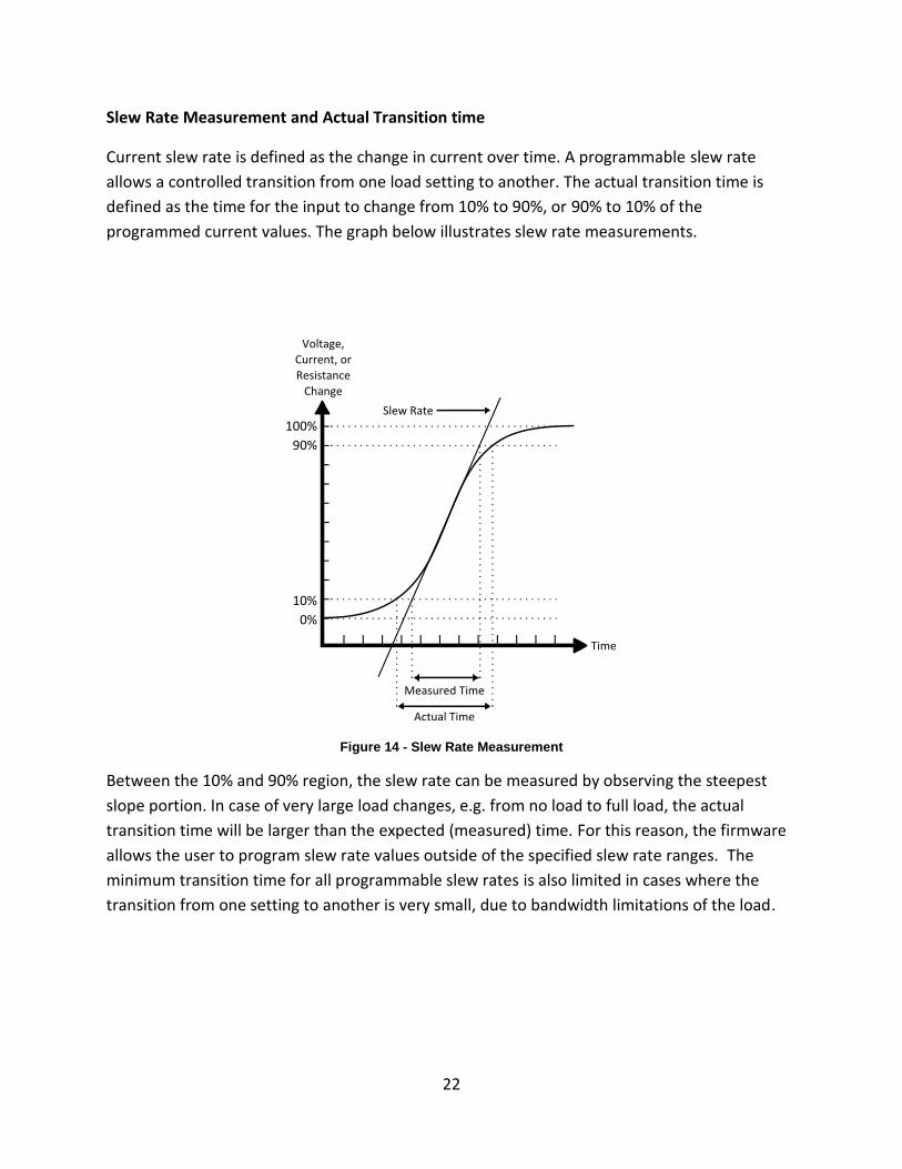
Slew Rate Measurement and Actual Transition time
Current slew rate is defined as the change in current over time. A programmable slew rate
allows a controlled transition from one load setting to another. The actual transition time is
defined as the time for the input to change from 10% to 90%, or 90% to 10% of the
programmed current values. The graph below illustrates slew rate measurements.
Figure 14 - Slew Rate Measurement
Between the 10% and 90% region, the slew rate can be measured by observing the steepest
slope portion. In case of very large load changes, e.g. from no load to full load, the actual
transition time will be larger than the expected (measured) time. For this reason, the firmware
allows the user to program slew rate values outside of the specified slew rate ranges. The
minimum transition time for all programmable slew rates is also limited in cases where the
transition from one setting to another is very small, due to bandwidth limitations of the load.
23
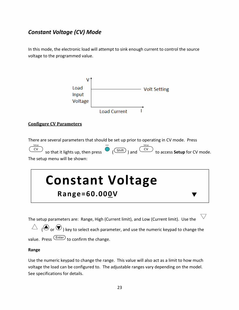
Constant Voltage (CV) Mode
In this mode, the electronic load will attempt to sink enough current to control the source
voltage to the programmed value.
Configure CV Parameters
There are several parameters that should be set up prior to operating in CV mode. Press
so that it lights up, then press ( ) and to access Setup for CV mode.
The setup menu will be shown:
The setup parameters are: Range, High (Current limit), and Low (Current limit). Use the
( or ) key to select each parameter, and use the numeric keypad to change the
value. Press to confirm the change.
Range
Use the numeric keypad to change the range. This value will also act as a limit to how much
voltage the load can be configured to. The adjustable ranges vary depending on the model.
See specifications for details.
Constant Voltage Range=60.000V
24
High
This parameter refers to the current high limit for the automatic test mode. During automatic
test mode, the device under test (DUT) must be operating below the configured value for the
test to PASS upon completion. If the DUT operates above the configured value, the test will FAIL
upon completion. Note: This parameter is used for Automatic Test Function ONLY.
Low
This parameter refers to the current low limit for the automatic test mode. During automatic
test mode, the DUT must be operating above the configured value for the test to PASS upon
completion. If the DUT operates below the configured value, the test will FAIL upon completion. Note: This parameter is used for Automatic Test Function ONLY.
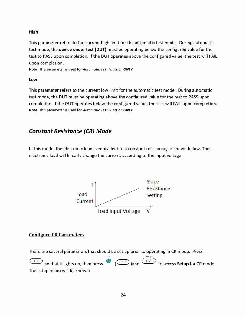
Constant Resistance (CR) Mode
In this mode, the electronic load is equivalent to a constant resistance, as shown below. The
electronic load will linearly change the current, according to the input voltage.
Configure CR Parameters
There are several parameters that should be set up prior to operating in CR mode. Press
so that it lights up, then press ( )and to access Setup for CR mode.
The setup menu will be shown:
25
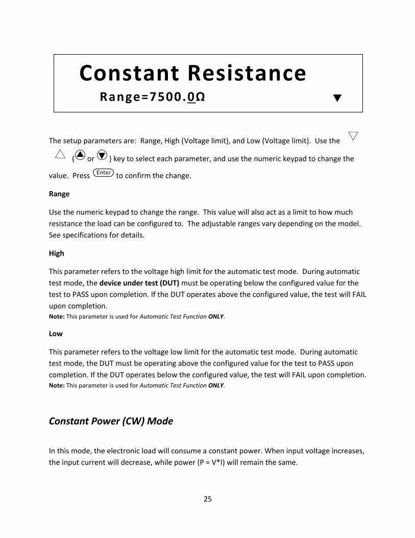
The setup parameters are: Range, High (Voltage limit), and Low (Voltage limit). Use the
( or ) key to select each parameter, and use the numeric keypad to change the
value. Press to confirm the change.
Range
Use the numeric keypad to change the range. This value will also act as a limit to how much
resistance the load can be configured to. The adjustable ranges vary depending on the model.
See specifications for details.
High
This parameter refers to the voltage high limit for the automatic test mode. During automatic
test mode, the device under test (DUT) must be operating below the configured value for the
test to PASS upon completion. If the DUT operates above the configured value, the test will FAIL
upon completion. Note: This parameter is used for Automatic Test Function ONLY.
Low
This parameter refers to the voltage low limit for the automatic test mode. During automatic
test mode, the DUT must be operating above the configured value for the test to PASS upon
completion. If the DUT operates below the configured value, the test will FAIL upon completion. Note: This parameter is used for Automatic Test Function ONLY.
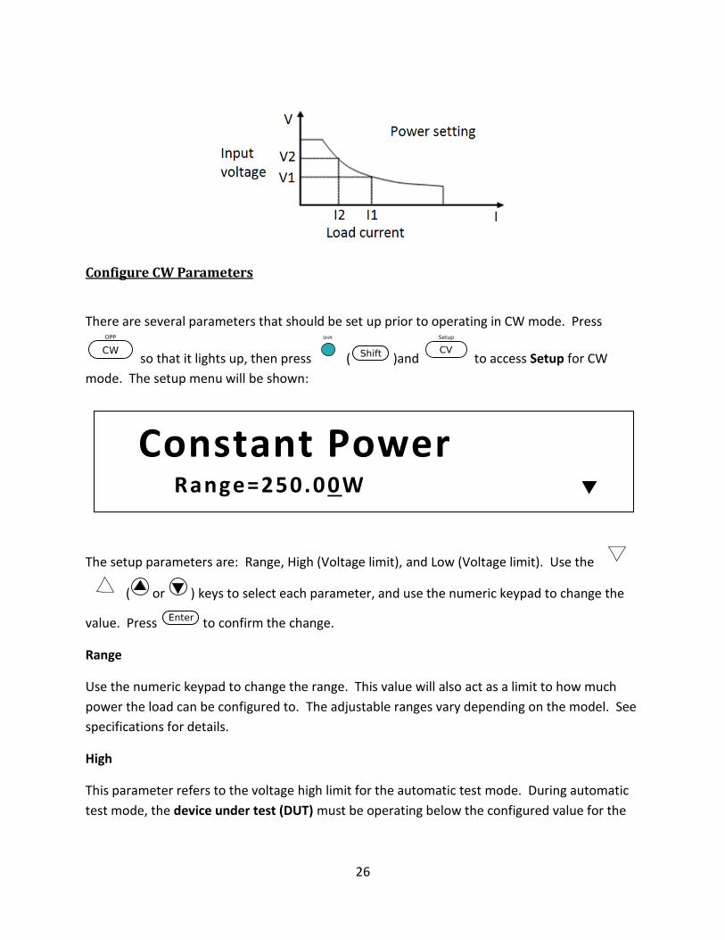
Constant Power (CW) Mode
In this mode, the electronic load will consume a constant power. When input voltage increases,
the input current will decrease, while power (P = V*I) will remain the same.
Constant Resistance Range=7500.0Ω
26
Configure CW Parameters
There are several parameters that should be set up prior to operating in CW mode. Press
so that it lights up, then press ( )and to access Setup for CW
mode. The setup menu will be shown:
The setup parameters are: Range, High (Voltage limit), and Low (Voltage limit). Use the
( or ) keys to select each parameter, and use the numeric keypad to change the
value. Press to confirm the change.
Range
Use the numeric keypad to change the range. This value will also act as a limit to how much
power the load can be configured to. The adjustable ranges vary depending on the model. See
specifications for details.
High
This parameter refers to the voltage high limit for the automatic test mode. During automatic
test mode, the device under test (DUT) must be operating below the configured value for the
Constant Power Range=250.00W
27
test to PASS upon completion. If the DUT operates above the configured value, the test will FAIL
upon completion.
Note: This parameter is used for Automatic Test Function ONLY.
Low
This parameter refers to the voltage low limit for the automatic test mode. During automatic
test mode, the DUT must be operating above the configured value for the test to PASS upon
completion. If the DUT operates below the configured value, the test will FAIL upon completion. Note: This parameter is used for Automatic Test Function ONLY.
Setting CC, CV, CR, CW Mode
Follow the steps below to configure the mode and enable the load.
1. Press / / / (for CC/CV/CR/CW mode) so that it lights up. 2. Use the numeric keypad or the rotary dial to enter the desired setting value.
3. Use the and ( or ) keys to change the cursor position to adjust different digits.
4. Press to enable the input.
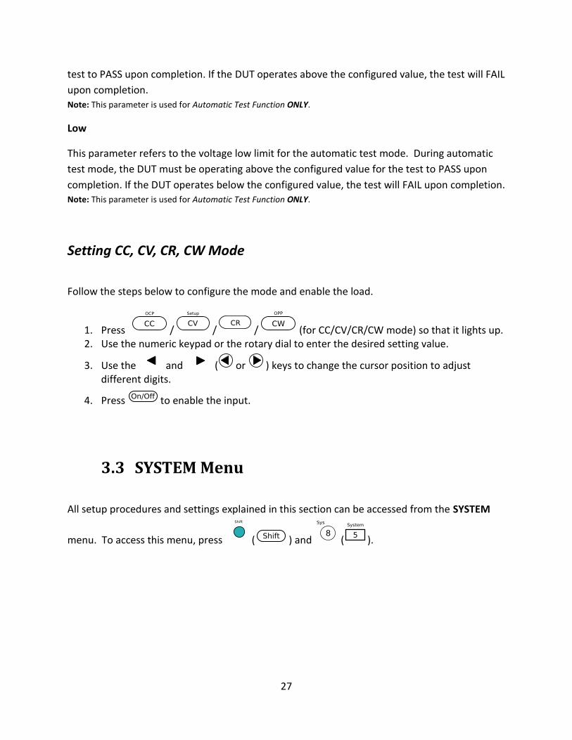
3.3 SYSTEM Menu
All setup procedures and settings explained in this section can be accessed from the SYSTEM
menu. To access this menu, press ( ) and ( ).
28
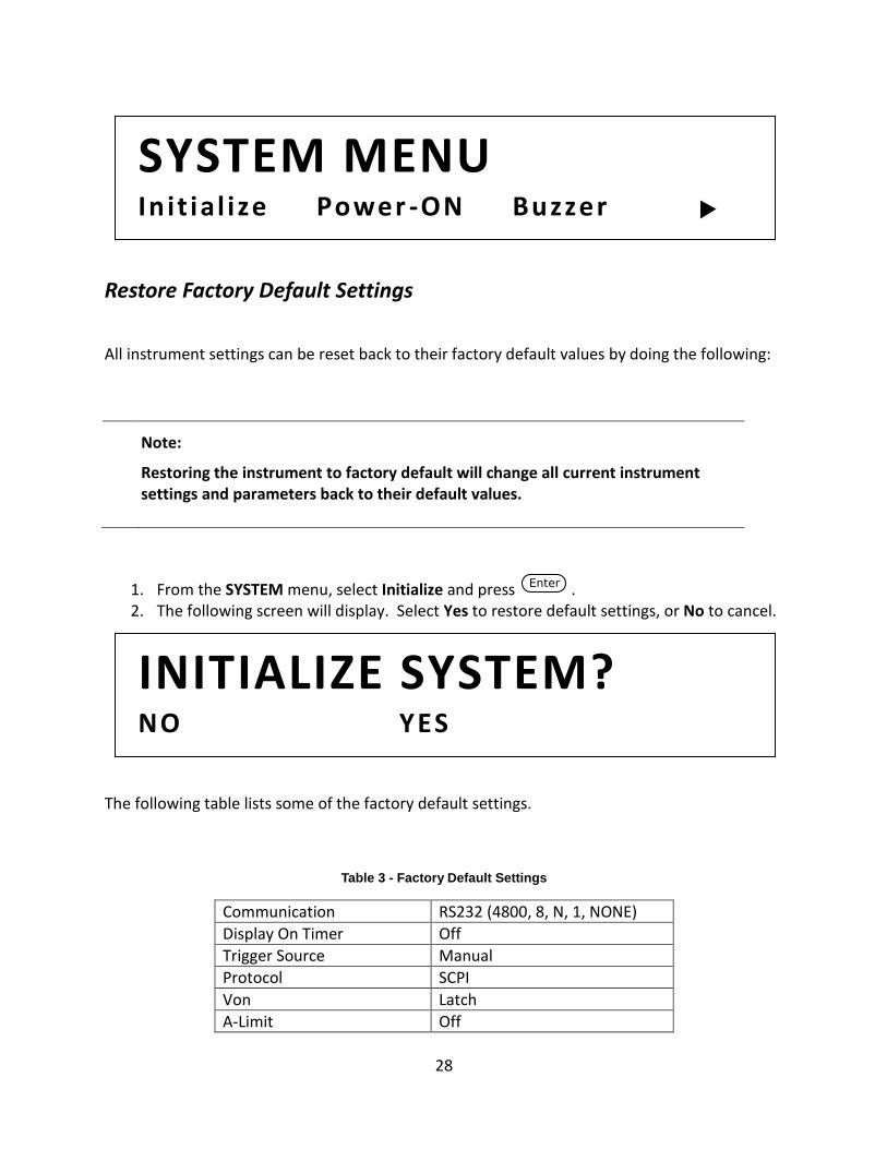
Restore Factory Default Settings
All instrument settings can be reset back to their factory default values by doing the following:
Note: Restoring the instrument to factory default will change all current instrument settings and parameters back to their default values.
1. From the SYSTEM menu, select Initialize and press . 2. The following screen will display. Select Yes to restore default settings, or No to cancel.
The following table lists some of the factory default settings.
Table 3 - Factory Default Settings
Communication RS232 (4800, 8, N, 1, NONE)
Display On Timer Off
Trigger Source Manual
Protocol SCPI
Von Latch
A-Limit Off
INITIALIZE SYSTEM? NO YES
SYSTEM MENU In it ial ize Power -ON Buzzer
29
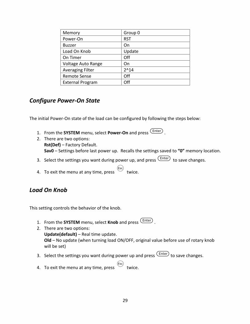
Memory Group 0
Power-On RST
Buzzer On
Load On Knob Update
On Timer Off
Voltage Auto Range On
Averaging Filter 2^14
Remote Sense Off
External Program Off
Configure Power-On State
The initial Power-On state of the load can be configured by following the steps below:
1. From the SYSTEM menu, select Power-On and press . 2. There are two options:
Rst(Def) – Factory Default. Sav0 – Settings before last power up. Recalls the settings saved to “0” memory location.
3. Select the settings you want during power up, and press to save changes.
4. To exit the menu at any time, press twice.
Load On Knob
This setting controls the behavior of the knob.
1. From the SYSTEM menu, select Knob and press . 2. There are two options:
Update(default) – Real time update. Old – No update (when turning load ON/OFF, original value before use of rotary knob will be set)
3. Select the settings you want during power up and press to save changes.
4. To exit the menu at any time, press twice.
30
Configure Trigger Source
The trigger function is used to initiate the start of a program in list mode and also as a toggle for
transient mode. The trigger source can be set so that users can send a trigger from the front
panel, through a remote command via remote interface or through the external trigger input in
the rear panel. Follow the steps below to configure the trigger mode:
1. From the SYSTEM menu, browse and select Trigger and press . 2. Here are the options:
Manual(Def) – Manual trigger. Front panel trigger button is used to send a trigger
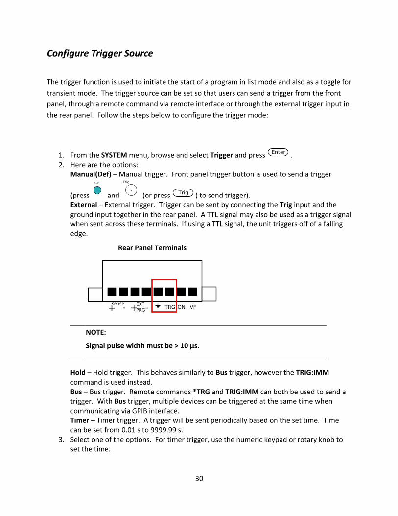
(press and (or press ) to send trigger). External – External trigger. Trigger can be sent by connecting the Trig input and the ground input together in the rear panel. A TTL signal may also be used as a trigger signal when sent across these terminals. If using a TTL signal, the unit triggers off of a falling edge.
NOTE: Signal pulse width must be > 10 µs.
Hold – Hold trigger. This behaves similarly to Bus trigger, however the TRIG:IMM command is used instead. Bus – Bus trigger. Remote commands *TRG and TRIG:IMM can both be used to send a trigger. With Bus trigger, multiple devices can be triggered at the same time when communicating via GPIB interface. Timer – Timer trigger. A trigger will be sent periodically based on the set time. Time can be set from 0.01 s to 9999.99 s.
3. Select one of the options. For timer trigger, use the numeric keypad or rotary knob to set the time.
Rear Panel Terminals
31
4. To exit the menu at any time, press twice.
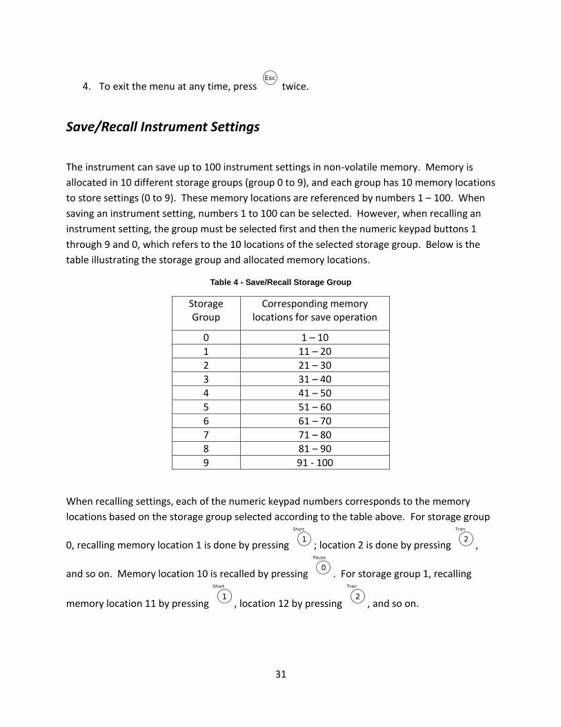
Save/Recall Instrument Settings
The instrument can save up to 100 instrument settings in non-volatile memory. Memory is
allocated in 10 different storage groups (group 0 to 9), and each group has 10 memory locations
to store settings (0 to 9). These memory locations are referenced by numbers 1 – 100. When
saving an instrument setting, numbers 1 to 100 can be selected. However, when recalling an
instrument setting, the group must be selected first and then the numeric keypad buttons 1
through 9 and 0, which refers to the 10 locations of the selected storage group. Below is the
table illustrating the storage group and allocated memory locations.
Table 4 - Save/Recall Storage Group
Storage Group
Corresponding memory locations for save operation
0 1 – 10
1 11 – 20
2 21 – 30
3 31 – 40
4 41 – 50
5 51 – 60
6 61 – 70
7 71 – 80
8 81 – 90
9 91 - 100
When recalling settings, each of the numeric keypad numbers corresponds to the memory
locations based on the storage group selected according to the table above. For storage group
0, recalling memory location 1 is done by pressing ; location 2 is done by pressing ,
and so on. Memory location 10 is recalled by pressing . For storage group 1, recalling
memory location 11 by pressing , location 12 by pressing , and so on.
32
Example:
Settings are saved to memory location 60. To recall those settings, set storage group to 5 from
the menu, then press recall and the number .
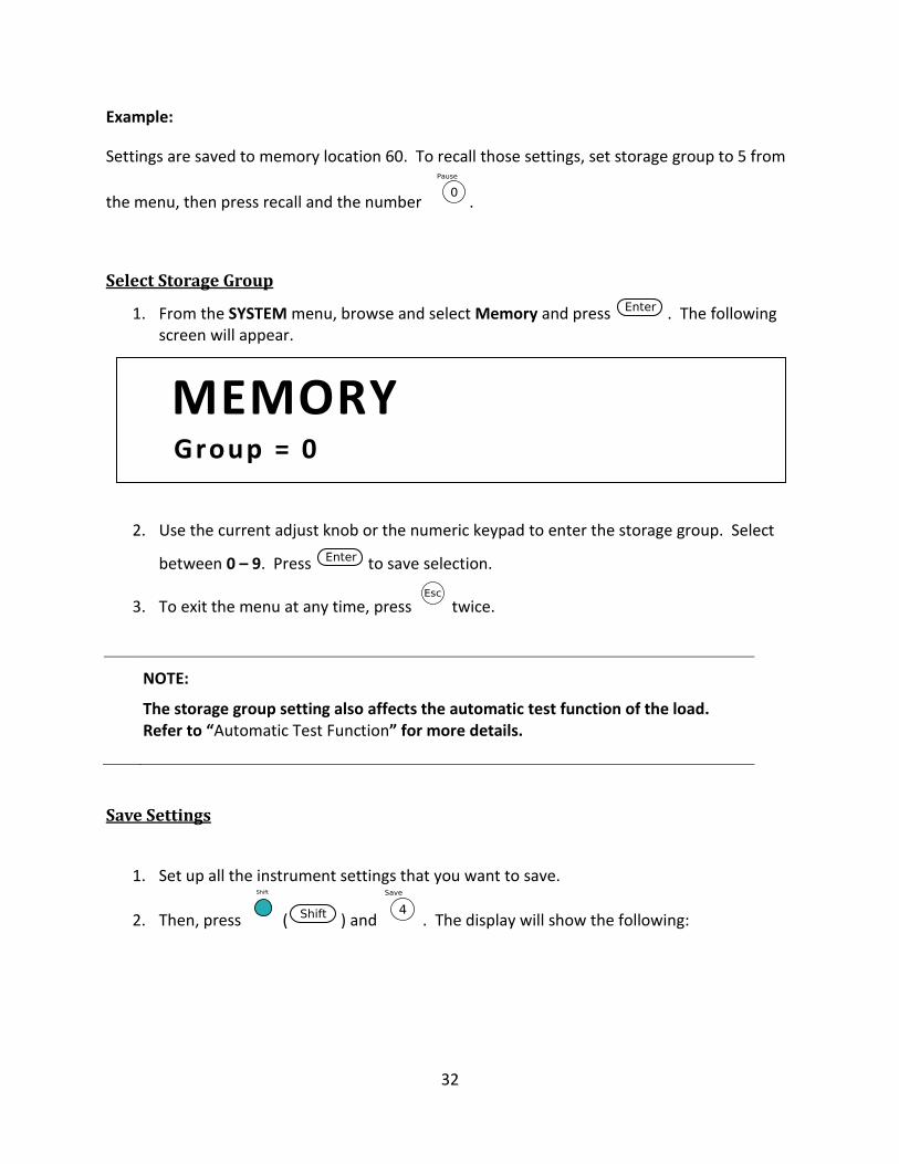
Select Storage Group
1. From the SYSTEM menu, browse and select Memory and press . The following screen will appear.
2. Use the current adjust knob or the numeric keypad to enter the storage group. Select
between 0 – 9. Press to save selection.
3. To exit the menu at any time, press twice.
NOTE: The storage group setting also affects the automatic test function of the load. Refer to “Automatic Test Function” for more details.
Save Settings
1. Set up all the instrument settings that you want to save.
2. Then, press ( ) and . The display will show the following:
MEMORY Group = 0
33
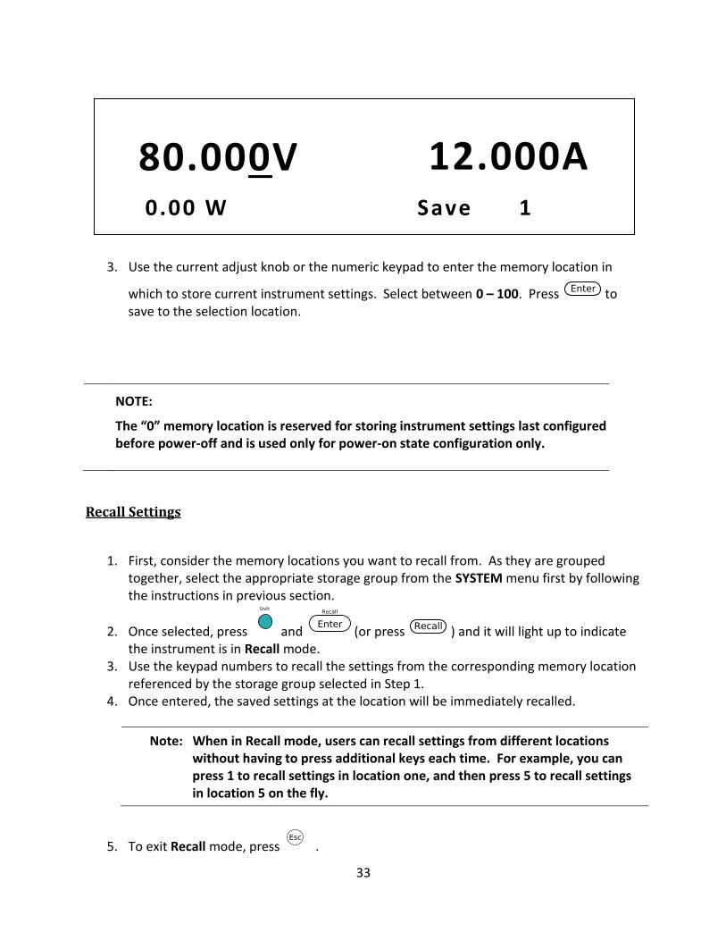
3. Use the current adjust knob or the numeric keypad to enter the memory location in
which to store current instrument settings. Select between 0 – 100. Press to save to the selection location.
NOTE: The “0” memory location is reserved for storing instrument settings last configured before power-off and is used only for power-on state configuration only.
Recall Settings
1. First, consider the memory locations you want to recall from. As they are grouped together, select the appropriate storage group from the SYSTEM menu first by following the instructions in previous section.
2. Once selected, press and (or press ) and it will light up to indicate the instrument is in Recall mode.
3. Use the keypad numbers to recall the settings from the corresponding memory location referenced by the storage group selected in Step 1.
4. Once entered, the saved settings at the location will be immediately recalled.
Note: When in Recall mode, users can recall settings from different locations without having to press additional keys each time. For example, you can press 1 to recall settings in location one, and then press 5 to recall settings in location 5 on the fly.
5. To exit Recall mode, press .
80.000V 12.000A 0.00 W Save 1
34
Display Input On Timer
The instrument has an internal timer that counts how long the input has been enabled (ON).
Follow the steps below to enable the timer display.
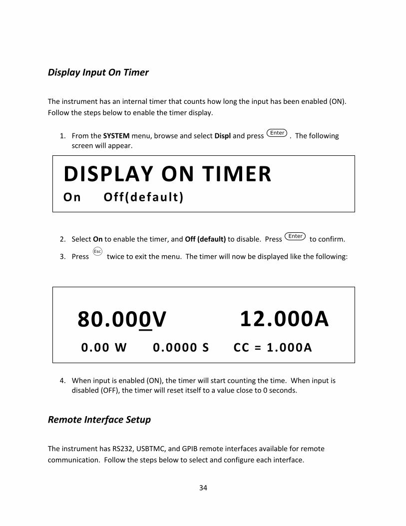
1. From the SYSTEM menu, browse and select Displ and press . The following screen will appear.
2. Select On to enable the timer, and Off (default) to disable. Press to confirm.
3. Press twice to exit the menu. The timer will now be displayed like the following:
4. When input is enabled (ON), the timer will start counting the time. When input is disabled (OFF), the timer will reset itself to a value close to 0 seconds.
Remote Interface Setup
The instrument has RS232, USBTMC, and GPIB remote interfaces available for remote
communication. Follow the steps below to select and configure each interface.
80.000V 12.000A 0.00 W 0.0000 S CC = 1.000A
DISPLAY ON TIMER On Off (default )
35
Note: The RMT indicator will appear on display when the instrument is successfully connected
to a PC remotely through any remote interface. Keys on the front panel will be locked until the
instrument is in LOCAL mode. To return to LOCAL mode from the front panel, press
( and then ) . The RMT indicator will disappear when the instrument is in LOCAL
mode.
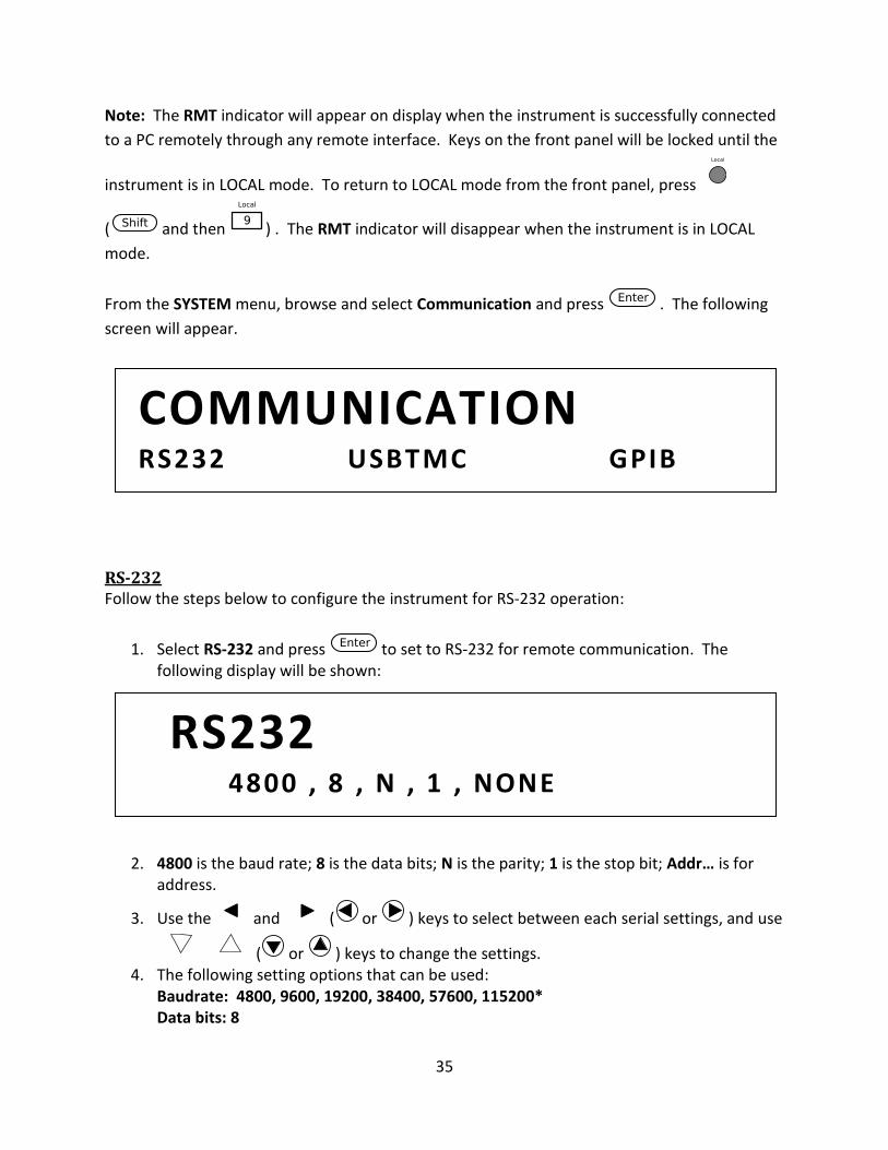
From the SYSTEM menu, browse and select Communication and press . The following
screen will appear.
RS-232 Follow the steps below to configure the instrument for RS-232 operation:
1. Select RS-232 and press to set to RS-232 for remote communication. The following display will be shown:
2. 4800 is the baud rate; 8 is the data bits; N is the parity; 1 is the stop bit; Addr… is for address.
3. Use the and ( or ) keys to select between each serial settings, and use
( or ) keys to change the settings. 4. The following setting options that can be used:
Baudrate: 4800, 9600, 19200, 38400, 57600, 115200* Data bits: 8
RS232 4800 , 8 , N , 1 , NONE
COMMUNICATION RS232 USBTMC GPIB
36
Parity: N (None), E (Even), O (Odd) Stop bit: 1 Flow control: NONE, CTS/RTS, XON/XOFF
Note: The default is 4800, 8, N, 1, NONE.
*Setting the baud rate to 115200 may provide unstable results during remote communication. Select a lower baud rate if communication errors occur.
5. All serial settings must match with the settings configured on the PC in order for communication to link successfully.
USBTMC
A USB Type A to Type B cable (i.e. USB printer cable) is required to connect the USB port in the
rear panel to a PC. Follow the steps below to setup the load for remote communication.
1. From the SYSTEM menu, browse and select Communication and press .
2. Select USBTMC and press to set USBTMC for remote communication. 3. Install the USB driver. For Windows® 7 and 8 users, this may install automatically. For
other users, visit www.bkprecision.com to download the driver.
Note: Users who have LabVIEW™ or NI-VISA installed will automatically have this driver in their system. In this case, driver download is not required.
GPIB Follow these instructions to select GPIB interface for remote operation.
1. From the SYSTEM menu, browse and select Communication and press .
2. Select GPIB and press to set to GPIB for remote communication. 3. The load will give a prompt to select an Address. This is the GPIB address to which the
instrument will be assigned to. 4. Use the current adjust knob or the numeric keypad to enter an address from 0 – 31.
5. Press to save the selected address and the display will return to the Communication menu.
37
3.4 CONFIG Menu
All setup procedures and settings explained in this section can be accessed from the CONFIG
menu. To access this menu, press ( ) and ( ). The following screen will
show:
Von Operation
The Von voltage value can be set to control the voltage turn on state for the electronic load.
When the input voltage exceeds the Von voltage value, the electronic load’s input state turns
on.
This function can protect a DUT when its voltage goes below a specified level. For example,
when testing a power supply’s discharge characteristics, you can set the Von voltage level start
and stop discharging of the power supply.
Note: Von Operation will have a short delay (< 1 s) from when a condition exceeds or goes
below a specified level to when the load’s input state changes.
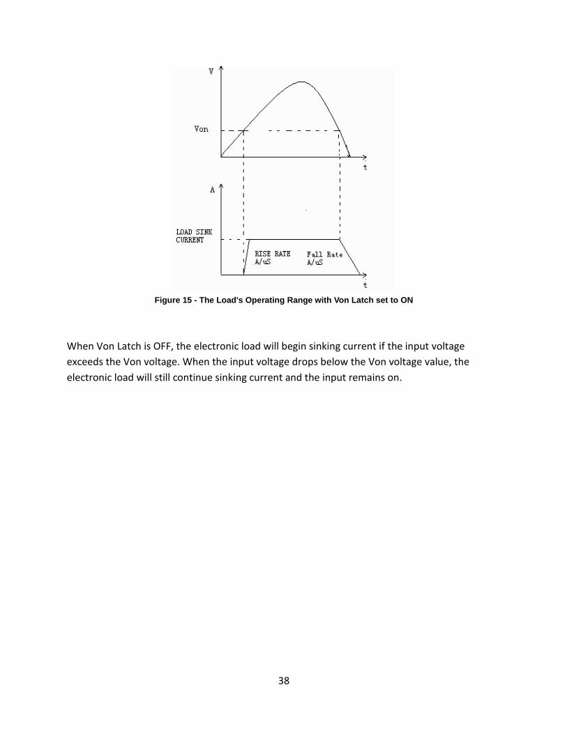
When Von Latch is ON, the electronic load will begin sinking current if input voltage exceeds
Von voltage. When the input voltage drops below the Von voltage value, the electronic load will
stop sinking current and the input will turn off.
CONFIG MENU Von Protect Measure CR_LED
38
Figure 15 - The Load's Operating Range with Von Latch set to ON
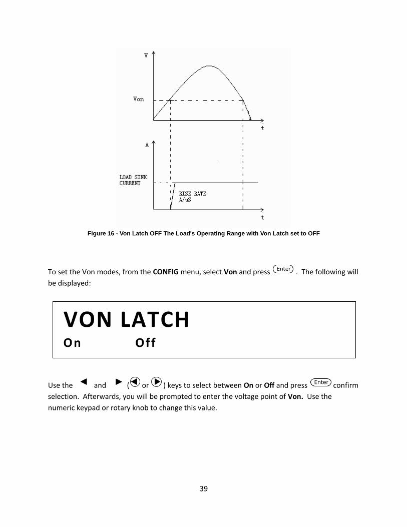
When Von Latch is OFF, the electronic load will begin sinking current if the input voltage
exceeds the Von voltage. When the input voltage drops below the Von voltage value, the
electronic load will still continue sinking current and the input remains on.
39
Figure 16 - Von Latch OFF The Load's Operating Range with Von Latch set to OFF
To set the Von modes, from the CONFIG menu, select Von and press . The following will
be displayed:
Use the and ( or ) keys to select between On or Off and press confirm
selection. Afterwards, you will be prompted to enter the voltage point of Von. Use the
numeric keypad or rotary knob to change this value.
VON LATCH On Off
40
Configure Protection Settings
The electronic load has the following protection functions: Overvoltage protection (OVP),
overcurrent protection (OCP), overpower protection (OPP), overtemperature protection (OTP),
and local and remote reverse voltage protection (LRV/RRV).
The instrument will act appropriately once any of the above protections are active. You can
press any button on the front panel to restore the protection function. For example, if the
electronic load triggers the overtemperature protection, the buzzer will alarm, the input will
automatically turn off, and the mainframe VFD will display OTP.
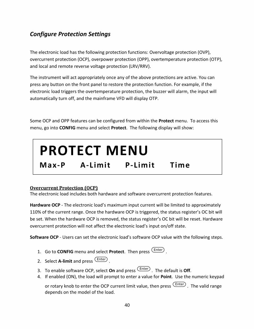
Some OCP and OPP features can be configured from within the Protect menu. To access this
menu, go into CONFIG menu and select Protect. The following display will show:
Overcurrent Protection (OCP) The electronic load includes both hardware and software overcurrent protection features.
Hardware OCP - The electronic load’s maximum input current will be limited to approximately
110% of the current range. Once the hardware OCP is triggered, the status register’s OC bit will
be set. When the hardware OCP is removed, the status register’s OC bit will be reset. Hardware
overcurrent protection will not affect the electronic load’s input on/off state.
Software OCP - Users can set the electronic load’s software OCP value with the following steps.
1. Go to CONFIG menu and select Protect. Then press .
2. Select A-limit and press .
3. To enable software OCP, select On and press . The default is Off. 4. If enabled (ON), the load will prompt to enter a value for Point. Use the numeric keypad
or rotary knob to enter the OCP current limit value, then press . The valid range depends on the model of the load.
PROTECT MENU Max-P A-L imit P-L imit T ime
41
5. It will then prompt to enter a value for Delay. This is the protection trip delay, which is the amount of time to delay from when the input has reached the limit before triggering
OCP. Use the numeric keypad or rotary knob to enter a value, then press to confirm change. The valid range is 0 – 60 seconds.
NOTE: Software OCP will disable the input if the input current has reached or exceeded the protection limits.
Operations to Clear the OCP State
Check whether the input current is within the electronic load’s rated current or the
programmed protection current ranges. If it is outside the range, disconnect the device under
test. Then press any key on the front panel or remotely send SCPI command PROTection:CLEar.
The OCP displayed on the front panel will turn off and the load exits OCP protection state.
Overpower Protection (OPP) The electronic load includes both hardware and software OPP features.
Hardware OPP – In the event that the electronic load’s input power exceeds the set power
protection limit, the hardware OPP will limit the power. Once the hardware OPP is triggered,
the status register’s OP bit will be set. When the hardware OPP is removed, the status register’s
OP bit will be reset. Hardware overpower protection will not turn the electronic load’s input off.
Follow the steps below to set the hardware OPP limit.
1. Go to CONFIG menu and select Protect. Then press .
2. Select Max-P and press . 3. The load will prompt to enter a value for Point. This is the hardware OPP limit value.
Use the numeric keypad or rotary knob to enter a value. Press to confirm the change.
42
Software OPP - Users can set the electronic load’s software OPP value with the following steps.
1. Go to CONFIG menu and select Protect. Then press .
2. Select P-limit and press .
3. To enable software OPP, select On and press . The default is Off. 4. If enabled (ON), the load will prompt to enter a value for Point. Use the numeric keypad
or rotary knob to enter the OPP power limit value, then press . The valid range depends on the model of the load.
5. It will then prompt to enter a value for Delay. This is the protection trip delay, which is the amount of time to delay from when the input has reached the limit before triggering
OPP. Use the numeric keypad or rotary knob to enter a value, then press to confirm change. The valid range is 0 – 60 seconds.
Operations to Clear the OPP State
Check whether the input power is within the rated power range or the programmed protection
ranges. If it is outside the range, disconnect the device under test. Then press any key on the
front panel or remotely send command PROTection:CLEar. The OPP displayed on the front
panel will turn off and the electronic load exits OPP protection state.
Overvoltage Protection (OVP) The instrument’s maximum OVP limit is 110% of the maximum rated voltage.
If the OVP circuit has triggered, input will turn off, buzzer alarm will go off, and the status
register’s OV and VF bit will be set. The mainframe will display OVP and the condition will
remain until they are reset. Once overvoltage protection occurs, the VF pin on the rear panel
will output TTL Low voltage level. Under normal conditions, it outputs a 5 V TTL high signal.
Operations to Clear the OVP State
Check whether the input voltage is within the electronic load’s rated voltage or the
programmed protection voltage ranges. If it is outside the range, please disconnect the device
under test. Then press any key on the front panel or remotely send SCPI command
PROTection:CLEar. The OVP displayed on the front panel will turn off and the electronic load
exits OVP protection state.
43
Overtemperature Protection (OTP) There is an overtemperature protection circuit, which will turn off the input if the internal
temperature exceeds safe limits. When the electronic load’s internal circuit temperature is over
85C, the load will enable OTP. Input will automatically be turned off and the VFD will display
OTP. At the same time the OT and PS bits in the status register will be set and remain until they
are reset.
Operations to Clear the OTP State
When the electronic load temperature has dropped below the protection point, press any key
on the front panel or remotely send command PROTection:CLEar. The OTP displayed on the
front panel will turn off and the electronic load exits OTP protection state.
Reverse Voltage Protection (LRV/RRV) This function protects the electronic load in case the input DC voltage lines are connected with
the wrong polarity. When a reverse voltage (LRV – local reverse voltage, RRV – remote reverse
voltage) connection condition is detected, the input will immediately turn off, the buzzer will
alarm the user, and the status register’s reverse voltage (LRV/RRV) and VF bits will be set. The
load will display LRV/RRV until they are reset.
In this condition, the VF pin will output a low level.
Operations to Clear the Reverse Voltage State
Check whether the connection is reversed. If so, disconnect the device to be measured and the
reverse voltage state will be cleared.
44
Configure Timed Input
The load has a built-in timer function that can be configured to allow enabling (ON) the main
input for a specified amount of time. To configure this time, follow the steps below:
1. Go to CONFIG menu and select Protect. Then press .
2. Select Time and press .
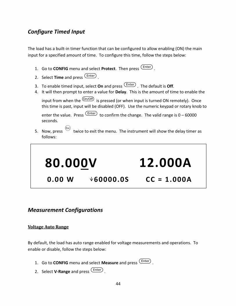
3. To enable timed input, select On and press . The default is Off. 4. It will then prompt to enter a value for Delay. This is the amount of time to enable the
input from when the is pressed (or when input is turned ON remotely). Once this time is past, input will be disabled (OFF). Use the numeric keypad or rotary knob to
enter the value. Press to confirm the change. The valid range is 0 – 60000 seconds.
5. Now, press twice to exit the menu. The instrument will show the delay timer as follows:
Measurement Configurations
Voltage Auto Range
By default, the load has auto range enabled for voltage measurements and operations. To
enable or disable, follow the steps below:
1. Go to CONFIG menu and select Measure and press .
2. Select V-Range and press .
80.000V 12.000A 0.00 W 60000.0S CC = 1 .000A
45
3. To enable voltage auto range, select On and press . To disable, select Off and
press to confirm the change.
Measuring Rise and Fall Time
The instrument can measure the rise or fall time from a specified start and stop voltage level of
the measured input. This feature requires the display timer to be enabled first. To enable
timer, please follow the instructions in the “Display Input On Timer” section of “3.3 SYSTEM
Menu”.
To setup this measurement, follow the steps below:
1. Go to CONFIG menu and select Measure. Then press .
2. Select TimeV1 and press . The load will prompt to enter a value. Use the
numeric keypad or rotary knob to set a value and press to confirm. This is for the start voltage level. When the measured input voltage reaches this level, the timer will start.
3. Now, select TimeV2 from the Measure menu and press . The load will prompt to
enter a value. Use the numeric keypad or rotary knob to set a value and press to confirm. This is for the stop voltage level. When the measured input voltage reaches this level, the timer will stop. The time on display will show the time difference between the measured start and stop voltage level.
Measurement Averaging Filter
The measurement averaging filter can be adjusted. Increasing the averaging will provide more
accurate readings, but slower measurement update rate. Decreasing the averaging will provide
faster measurement update rate, but less accurate readings.
To configure, follow the steps below:
4. Go to CONFIG menu and select Measure. Then press .
5. Select Filter and press . The load will prompt to enter a value for Average Count.
6. Use the numeric keypad or rotary knob to adjust this value, then press to save the change. The valid range is from 2 – 16 (2^2 – 2^16). The default is 14 (2^14).
46
CR LED Function
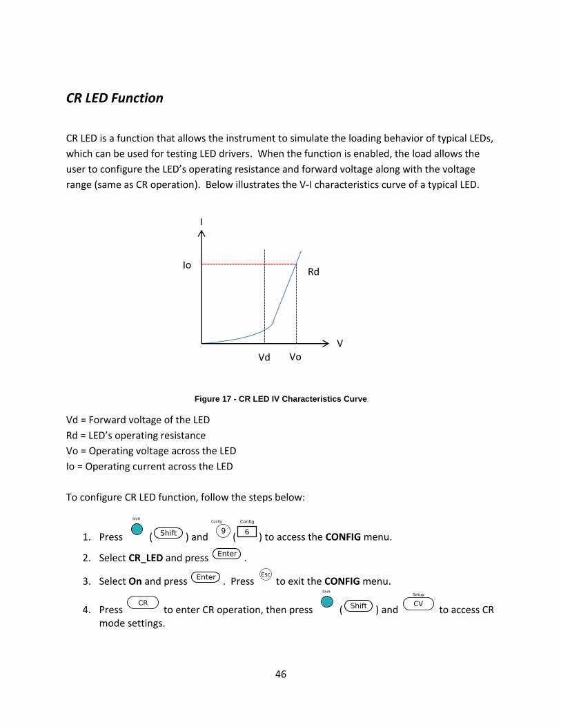
CR LED is a function that allows the instrument to simulate the loading behavior of typical LEDs,
which can be used for testing LED drivers. When the function is enabled, the load allows the
user to configure the LED’s operating resistance and forward voltage along with the voltage
range (same as CR operation). Below illustrates the V-I characteristics curve of a typical LED.
Figure 17 - CR LED IV Characteristics Curve
Vd = Forward voltage of the LED
Rd = LED’s operating resistance
Vo = Operating voltage across the LED
Io = Operating current across the LED
To configure CR LED function, follow the steps below:
1. Press ( ) and ( ) to access the CONFIG menu.
2. Select CR_LED and press .
3. Select On and press . Press to exit the CONFIG menu.
4. Press to enter CR operation, then press ( ) and to access CR mode settings.
I
V
Io
Vo
Rd
Vd
47
5. Use the numeric keypad or rotary knob to enter the values for Range, Voltage High, Voltage Low, and Vd. Vd will be the forward voltage of the LED you want to simulate. This option will only appear after CR_LED has been enabled from the CONFIG menu.
6. While in CR mode, use the numeric keypad or rotary knob to enter a value for Rd, the resistance.
7. Now that both Vd and Rd are configured, turn ON the input by pressing .
Remote Sense
Remote sense can be used to compensate for voltage drops (up to 1 V) due to resistance from
test leads connected to your device under test (DUT), thus providing more accurate voltage
measurement. The instrument is setup with remote sense disabled by default.
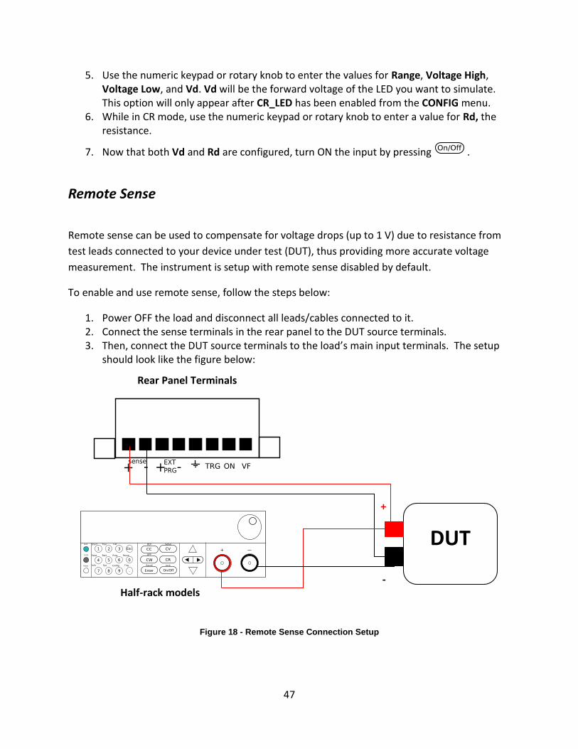
To enable and use remote sense, follow the steps below:
1. Power OFF the load and disconnect all leads/cables connected to it. 2. Connect the sense terminals in the rear panel to the DUT source terminals. 3. Then, connect the DUT source terminals to the load’s main input terminals. The setup
should look like the figure below:
Figure 18 - Remote Sense Connection Setup
Half-rack models
Rear Panel Terminals
DUT
+
-
48
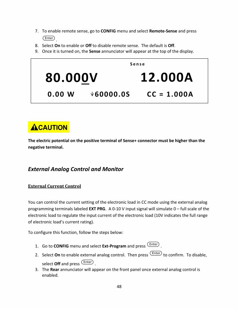
7. To enable remote sense, go to CONFIG menu and select Remote-Sense and press
. 8. Select On to enable or Off to disable remote sense. The default is Off. 9. Once it is turned on, the Sense annunciator will appear at the top of the display.
The electric potential on the positive terminal of Sense+ connector must be higher than the
negative terminal.
External Analog Control and Monitor
External Current Control
You can control the current setting of the electronic load in CC mode using the external analog
programming terminals labeled EXT PRG. A 0-10 V input signal will simulate 0 – full scale of the
electronic load to regulate the input current of the electronic load (10V indicates the full range
of electronic load’s current rating).
To configure this function, follow the steps below:
1. Go to CONFIG menu and select Ext-Program and press .
2. Select On to enable external analog control. Then press to confirm. To disable,
select Off and press . 3. The Rear annunciator will appear on the front panel once external analog control is
enabled.
80.000V 12.000A 0.00 W 60000.0S CC = 1 .000A
S e n s e
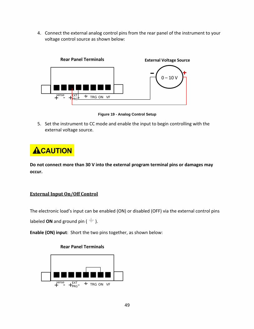
49
4. Connect the external analog control pins from the rear panel of the instrument to your voltage control source as shown below:
Figure 19 - Analog Control Setup
5. Set the instrument to CC mode and enable the input to begin controlling with the external voltage source.
Do not connect more than 30 V into the external program terminal pins or damages may
occur.
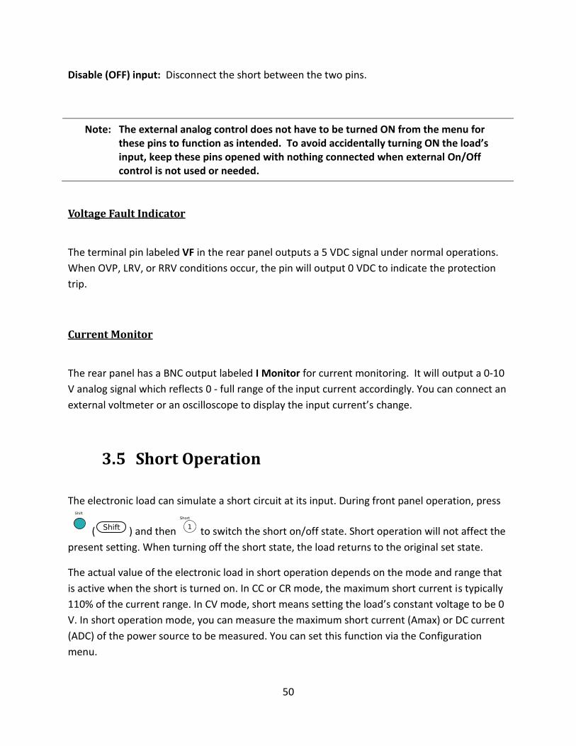
External Input On/Off Control
The electronic load’s input can be enabled (ON) or disabled (OFF) via the external control pins
labeled ON and ground pin ( ).
Enable (ON) input: Short the two pins together, as shown below:
Rear Panel Terminals
Rear Panel Terminals
0 – 10 V
External Voltage Source
50
Disable (OFF) input: Disconnect the short between the two pins.
Note: The external analog control does not have to be turned ON from the menu for these pins to function as intended. To avoid accidentally turning ON the load’s input, keep these pins opened with nothing connected when external On/Off control is not used or needed.
Voltage Fault Indicator
The terminal pin labeled VF in the rear panel outputs a 5 VDC signal under normal operations.
When OVP, LRV, or RRV conditions occur, the pin will output 0 VDC to indicate the protection
trip.
Current Monitor
The rear panel has a BNC output labeled I Monitor for current monitoring. It will output a 0-10
V analog signal which reflects 0 - full range of the input current accordingly. You can connect an
external voltmeter or an oscilloscope to display the input current’s change.
3.5 Short Operation
The electronic load can simulate a short circuit at its input. During front panel operation, press
( ) and then to switch the short on/off state. Short operation will not affect the
present setting. When turning off the short state, the load returns to the original set state.
The actual value of the electronic load in short operation depends on the mode and range that
is active when the short is turned on. In CC or CR mode, the maximum short current is typically
110% of the current range. In CV mode, short means setting the load’s constant voltage to be 0
V. In short operation mode, you can measure the maximum short current (Amax) or DC current
(ADC) of the power source to be measured. You can set this function via the Configuration
menu.
51
3.6 Transient Operation
Transient operation enables the module to periodically switch between two load levels, as
might be required for testing power supplies or other DC sources. There are three different
transient testing modes: continuous, pulse, and toggle.
Continuous Generates a respective pulse stream that toggles between two load levels.
Pulse Generates a load change that returns to its original state after some time period.
Toggle
Generates a repetitive pulse stream that toggles between two load levels.
It is similar to continuous mode except that the transient points are controlled
by explicit triggers instead of an internal transient generator.
Continuous In this mode, the electronic load generates a repetitive pulse stream that toggles between two
load levels. Load could switch the state between two value settings, value A and value B.
In CC mode, transient testing can be used to check the stability of the source voltage. Transient
functions have two current levels (A level, B level), which should be in the same range (high
range or low range). You can set the frequency as well as the duty cycle, which will affect the
timing and width of each level.
The slew rate determines the rate at which the level changes. Upon receiving a trigger, and the
load will continuously switch between the A/B levels preset. Transient loads are usually used to
test the power supply’s performance under continuous changing load conditions. Figure 20
shows the current waveform of continuous transient operation mode.
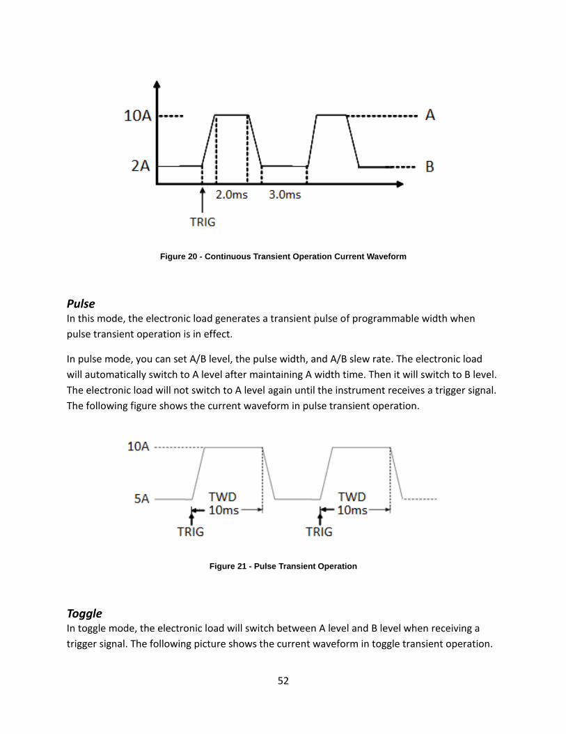
52
Figure 20 - Continuous Transient Operation Current Waveform
Pulse In this mode, the electronic load generates a transient pulse of programmable width when
pulse transient operation is in effect.
In pulse mode, you can set A/B level, the pulse width, and A/B slew rate. The electronic load
will automatically switch to A level after maintaining A width time. Then it will switch to B level.
The electronic load will not switch to A level again until the instrument receives a trigger signal.
The following figure shows the current waveform in pulse transient operation.
Figure 21 - Pulse Transient Operation
Toggle In toggle mode, the electronic load will switch between A level and B level when receiving a
trigger signal. The following picture shows the current waveform in toggle transient operation.
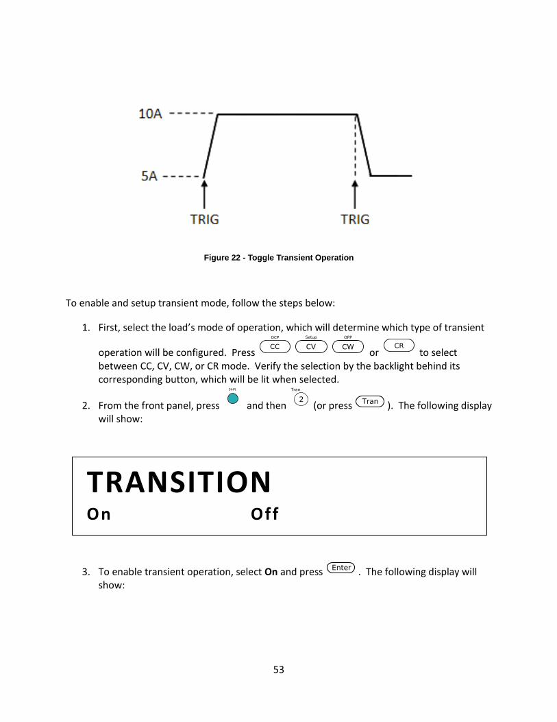
53
Figure 22 - Toggle Transient Operation
To enable and setup transient mode, follow the steps below:
1. First, select the load’s mode of operation, which will determine which type of transient
operation will be configured. Press or to select between CC, CV, CW, or CR mode. Verify the selection by the backlight behind its corresponding button, which will be lit when selected.
2. From the front panel, press and then (or press ). The following display will show:
3. To enable transient operation, select On and press . The following display will show:
TRANSITION On Off
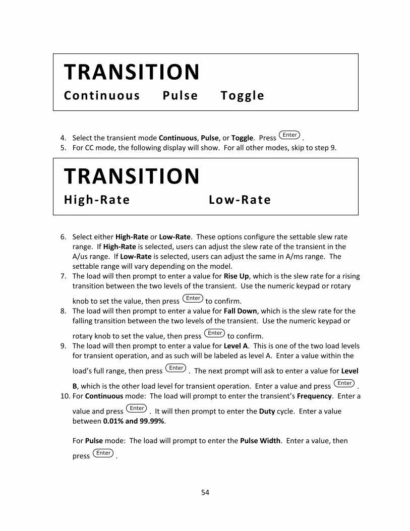
54
4. Select the transient mode Continuous, Pulse, or Toggle. Press . 5. For CC mode, the following display will show. For all other modes, skip to step 9.
6. Select either High-Rate or Low-Rate. These options configure the settable slew rate range. If High-Rate is selected, users can adjust the slew rate of the transient in the A/us range. If Low-Rate is selected, users can adjust the same in A/ms range. The settable range will vary depending on the model.
7. The load will then prompt to enter a value for Rise Up, which is the slew rate for a rising transition between the two levels of the transient. Use the numeric keypad or rotary
knob to set the value, then press to confirm. 8. The load will then prompt to enter a value for Fall Down, which is the slew rate for the
falling transition between the two levels of the transient. Use the numeric keypad or
rotary knob to set the value, then press to confirm. 9. The load will then prompt to enter a value for Level A. This is one of the two load levels
for transient operation, and as such will be labeled as level A. Enter a value within the
load’s full range, then press . The next prompt will ask to enter a value for Level
B, which is the other load level for transient operation. Enter a value and press . 10. For Continuous mode: The load will prompt to enter the transient’s Frequency. Enter a
value and press . It will then prompt to enter the Duty cycle. Enter a value between 0.01% and 99.99%. For Pulse mode: The load will prompt to enter the Pulse Width. Enter a value, then
press .
TRANSITION High-Rate Low-Rate
TRANSITION Continuous Pulse Toggle
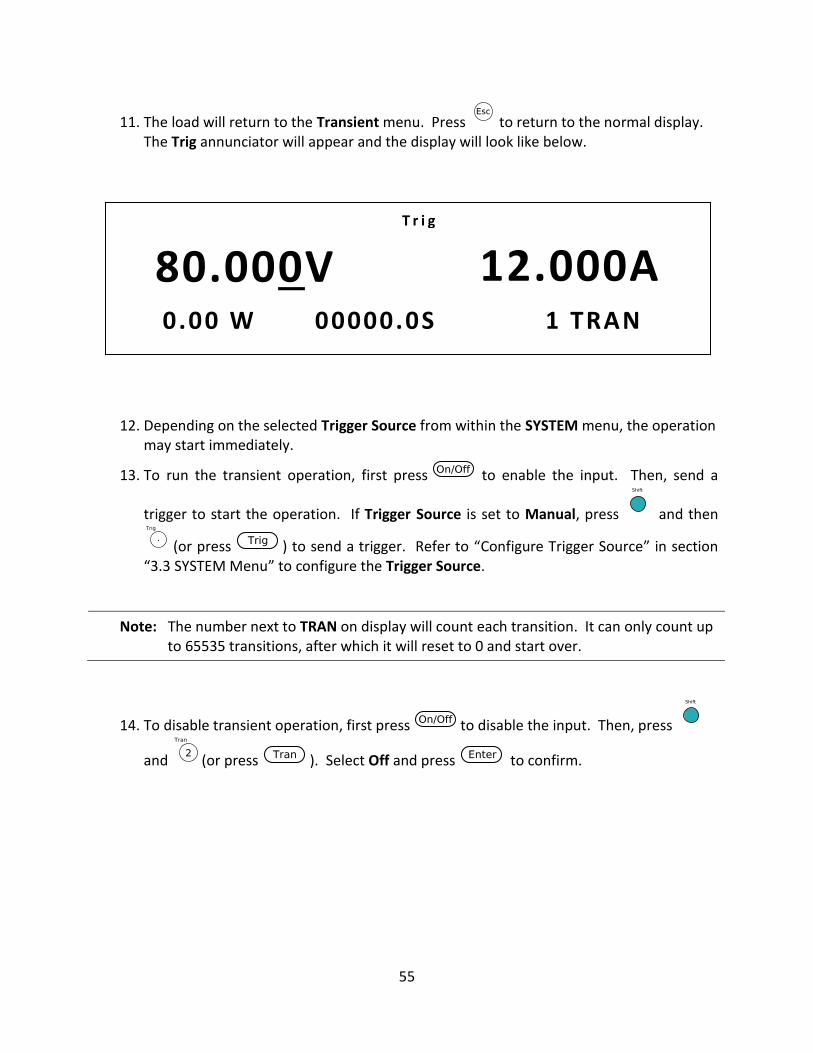
55
11. The load will return to the Transient menu. Press to return to the normal display. The Trig annunciator will appear and the display will look like below.
12. Depending on the selected Trigger Source from within the SYSTEM menu, the operation may start immediately.
13. To run the transient operation, first press to enable the input. Then, send a
trigger to start the operation. If Trigger Source is set to Manual, press and then
(or press ) to send a trigger. Refer to “Configure Trigger Source” in section “3.3 SYSTEM Menu” to configure the Trigger Source.
Note: The number next to TRAN on display will count each transition. It can only count up to 65535 transitions, after which it will reset to 0 and start over.
14. To disable transient operation, first press to disable the input. Then, press
and (or press ). Select Off and press to confirm.
80.000V 12.000A 0.00 W 00000.0S 1 TRAN
T r i g
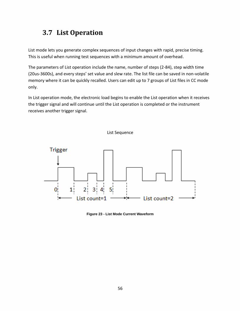
56
3.7 List Operation
List mode lets you generate complex sequences of input changes with rapid, precise timing.
This is useful when running test sequences with a minimum amount of overhead.
The parameters of List operation include the name, number of steps (2-84), step width time
(20us-3600s), and every steps’ set value and slew rate. The list file can be saved in non-volatile
memory where it can be quickly recalled. Users can edit up to 7 groups of List files in CC mode
only.
In List operation mode, the electronic load begins to enable the List operation when it receives
the trigger signal and will continue until the List operation is completed or the instrument
receives another trigger signal.
List Sequence
Figure 23 - List Mode Current Waveform
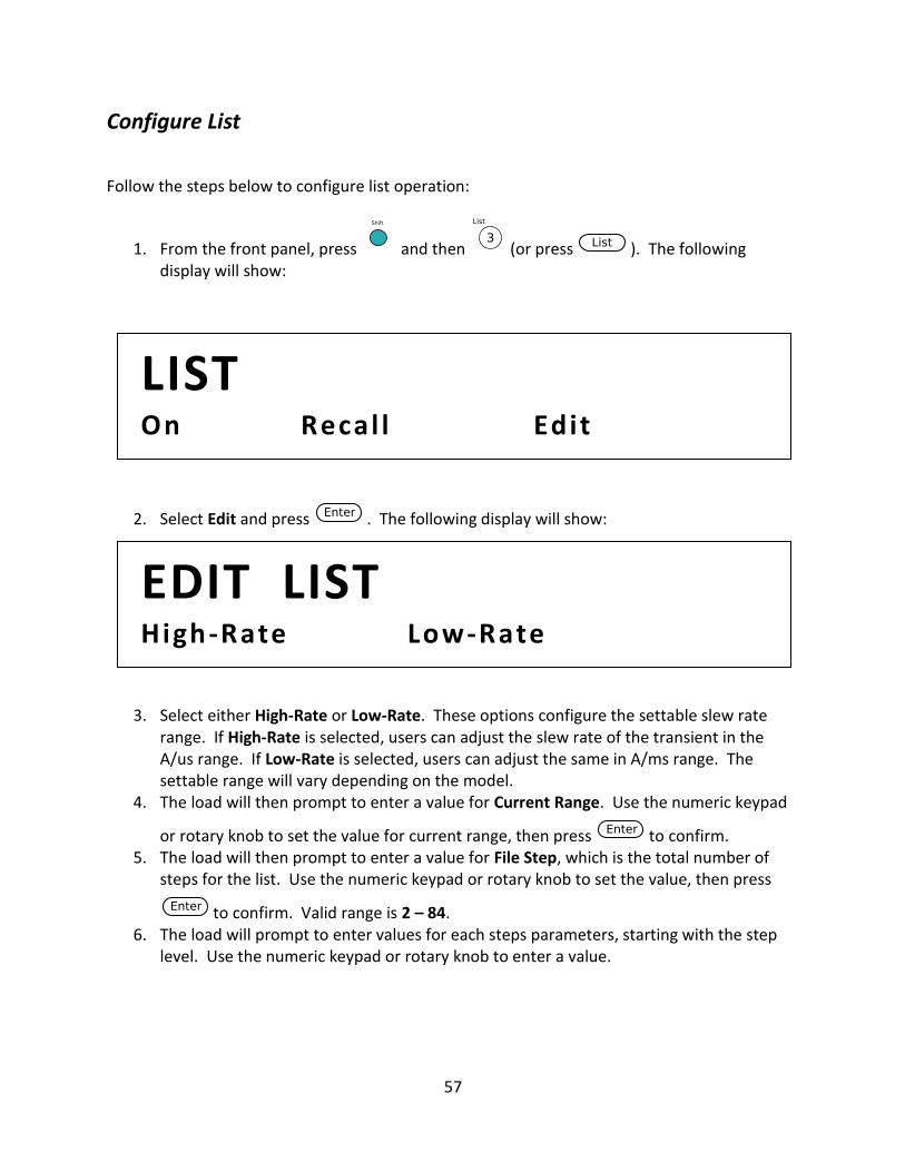
57
Configure List
Follow the steps below to configure list operation:
1. From the front panel, press and then (or press ). The following display will show:
2. Select Edit and press . The following display will show:
3. Select either High-Rate or Low-Rate. These options configure the settable slew rate range. If High-Rate is selected, users can adjust the slew rate of the transient in the A/us range. If Low-Rate is selected, users can adjust the same in A/ms range. The settable range will vary depending on the model.
4. The load will then prompt to enter a value for Current Range. Use the numeric keypad
or rotary knob to set the value for current range, then press to confirm. 5. The load will then prompt to enter a value for File Step, which is the total number of
steps for the list. Use the numeric keypad or rotary knob to set the value, then press
to confirm. Valid range is 2 – 84. 6. The load will prompt to enter values for each steps parameters, starting with the step
level. Use the numeric keypad or rotary knob to enter a value.
EDIT LIST High-Rate Low-Rate
LIST On Recal l Edit
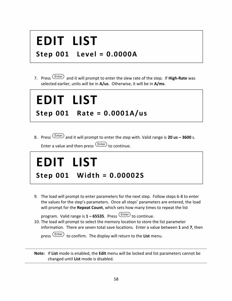
58
7. Press and it will prompt to enter the slew rate of the step. If High-Rate was selected earlier, units will be in A/us. Otherwise, it will be in A/ms.
8. Press and it will prompt to enter the step with. Valid range is 20 us – 3600 s.
Enter a value and then press to continue.
9. The load will prompt to enter parameters for the next step. Follow steps 6-8 to enter the values for the step’s parameters. Once all steps’ parameters are entered, the load will prompt for the Repeat Count, which sets how many times to repeat the list
program. Valid range is 1 – 65535. Press to continue. 10. The load will prompt to select the memory location to store the list parameter
information. There are seven total save locations. Enter a value between 1 and 7, then
press to confirm. The display will return to the List menu.
Note: If List mode is enabled, the Edit menu will be locked and list parameters cannot be changed until List mode is disabled.
EDIT LIST Step 001 Width = 0.00002S
EDIT LIST Step 001 Rate = 0.0001A/us
EDIT LIST Step 001 Level = 0.0000A
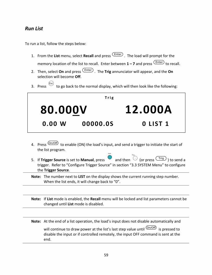
59
Run List
To run a list, follow the steps below:
1. From the List menu, select Recall and press . The load will prompt for the
memory location of the list to recall. Enter between 1 – 7 and press to recall.
2. Then, select On and press . The Trig annunciator will appear, and the On selection will become Off.
3. Press to go back to the normal display, which will then look like the following:
4. Press to enable (ON) the load’s input, and send a trigger to initiate the start of the list program.
5. If Trigger Source is set to Manual, press and then (or press ) to send a trigger. Refer to “Configure Trigger Source” in section “3.3 SYSTEM Menu” to configure the Trigger Source.
Note: The number next to LIST on the display shows the current running step number. When the list ends, it will change back to “0”.
Note: If List mode is enabled, the Recall menu will be locked and list parameters cannot be changed until List mode is disabled.
Note: At the end of a list operation, the load’s input does not disable automatically and
will continue to draw power at the list’s last step value until is pressed to disable the input or if controlled remotely, the input OFF command is sent at the end.
80.000V 12.000A 0.00 W 00000.0S 0 L IST 1
T r i g
60
6. To disable list operation, first press to disable the input and then press and
(or press ). Select Off and press to confirm. The Trig annunciator will disappear when list operation is disabled.
3.8 Battery Test Function
The load has a built-in battery test function that uses CC mode and calculates the battery
capacity using a fixed current load. The test’s stop conditions can be specified by the following:
Stop Voltage: Set a cut-off voltage level. When this level is reached, the test will end. Valid
range: 0 V – max. rated voltage.
Stop Capacity: Sets a capacity level. When the calculated capacity reaches this level, the test
will end. Valid range: 0 Ah – 999.99 Ah
Stop Timer: Sets a timer. When the specified time is reached, the test will end. Valid range: 0
s – 99999 s.
During operation, the load will sink current at the specified level while measuring and updating
the capacity value in amp-hours (Ah) and tracking the time period of the test. When any one of
the three stop conditions above is met, the test will end, and the display will show the
measured capacity and time results.
To setup and run the battery test function, follow the steps below:
1. Disable the input of the load and connect it to the battery to be tested.
2. Press and use the numeric keypad or rotary knob to enter a current sink value
for the test. Press .
3. Press ( ) and ( ) to configure and enable the battery test function. 4. The load will prompt to enter all three test stop conditions, starting with Stop Voltage
value. Use the numeric keypad or rotary knob to enter a voltage level. Then press
to continue. 5. The load will prompt to enter the Stop Capacity. Use the numeric keypad or rotary
knob to enter a capacity value in Ah. Then press to continue.
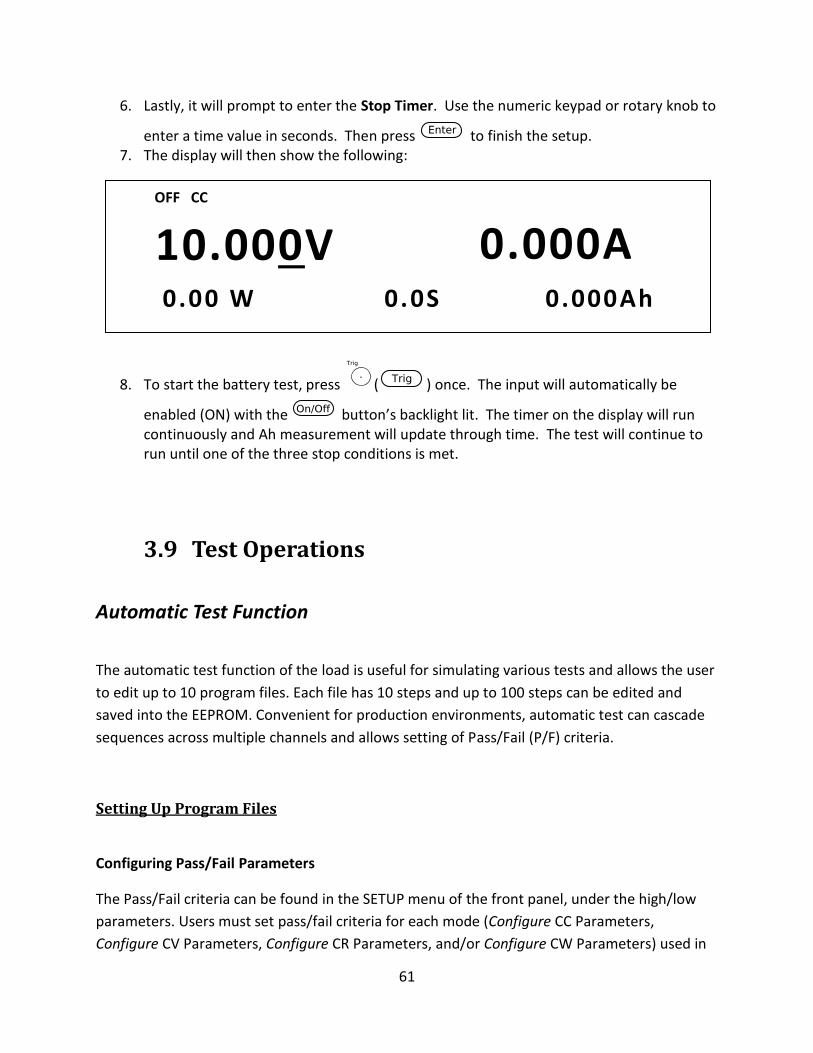
61
6. Lastly, it will prompt to enter the Stop Timer. Use the numeric keypad or rotary knob to
enter a time value in seconds. Then press to finish the setup. 7. The display will then show the following:
8. To start the battery test, press ( ) once. The input will automatically be
enabled (ON) with the button’s backlight lit. The timer on the display will run continuously and Ah measurement will update through time. The test will continue to run until one of the three stop conditions is met.
3.9 Test Operations
Automatic Test Function
The automatic test function of the load is useful for simulating various tests and allows the user
to edit up to 10 program files. Each file has 10 steps and up to 100 steps can be edited and
saved into the EEPROM. Convenient for production environments, automatic test can cascade
sequences across multiple channels and allows setting of Pass/Fail (P/F) criteria.
Setting Up Program Files
Configuring Pass/Fail Parameters
The Pass/Fail criteria can be found in the SETUP menu of the front panel, under the high/low
parameters. Users must set pass/fail criteria for each mode (Configure CC Parameters,
Configure CV Parameters, Configure CR Parameters, and/or Configure CW Parameters) used in
10.000V 0.000A 0.00 W 0 .0S 0 .000Ah
OFF CC
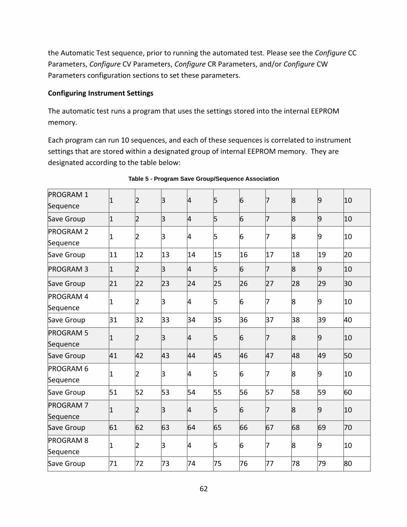
62
the Automatic Test sequence, prior to running the automated test. Please see the Configure CC
Parameters, Configure CV Parameters, Configure CR Parameters, and/or Configure CW
Parameters configuration sections to set these parameters.
Configuring Instrument Settings
The automatic test runs a program that uses the settings stored into the internal EEPROM
memory.
Each program can run 10 sequences, and each of these sequences is correlated to instrument
settings that are stored within a designated group of internal EEPROM memory. They are
designated according to the table below:
Table 5 - Program Save Group/Sequence Association
PROGRAM 1
Sequence 1 2 3 4 5 6 7 8 9 10
Save Group 1 2 3 4 5 6 7 8 9 10
PROGRAM 2
Sequence 1 2 3 4 5 6 7 8 9 10
Save Group 11 12 13 14 15 16 17 18 19 20
PROGRAM 3 1 2 3 4 5 6 7 8 9 10
Save Group 21 22 23 24 25 26 27 28 29 30
PROGRAM 4
Sequence 1 2 3 4 5 6 7 8 9 10
Save Group 31 32 33 34 35 36 37 38 39 40
PROGRAM 5
Sequence 1 2 3 4 5 6 7 8 9 10
Save Group 41 42 43 44 45 46 47 48 49 50
PROGRAM 6
Sequence 1 2 3 4 5 6 7 8 9 10
Save Group 51 52 53 54 55 56 57 58 59 60
PROGRAM 7
Sequence 1 2 3 4 5 6 7 8 9 10
Save Group 61 62 63 64 65 66 67 68 69 70
PROGRAM 8
Sequence 1 2 3 4 5 6 7 8 9 10
Save Group 71 72 73 74 75 76 77 78 79 80
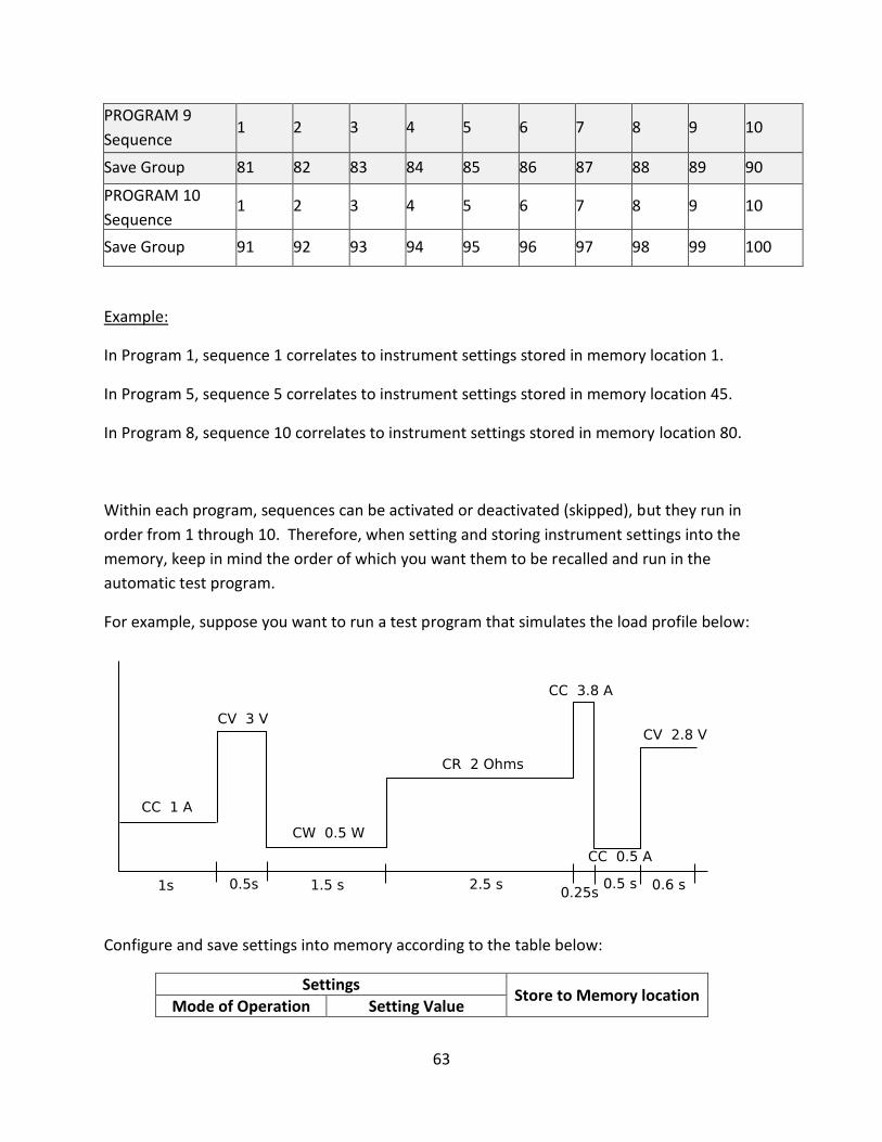
63
PROGRAM 9
Sequence 1 2 3 4 5 6 7 8 9 10
Save Group 81 82 83 84 85 86 87 88 89 90
PROGRAM 10
Sequence 1 2 3 4 5 6 7 8 9 10
Save Group 91 92 93 94 95 96 97 98 99 100
Example:
In Program 1, sequence 1 correlates to instrument settings stored in memory location 1.
In Program 5, sequence 5 correlates to instrument settings stored in memory location 45.
In Program 8, sequence 10 correlates to instrument settings stored in memory location 80.
Within each program, sequences can be activated or deactivated (skipped), but they run in
order from 1 through 10. Therefore, when setting and storing instrument settings into the
memory, keep in mind the order of which you want them to be recalled and run in the
automatic test program.
For example, suppose you want to run a test program that simulates the load profile below:
Configure and save settings into memory according to the table below:
Settings Store to Memory location
Mode of Operation Setting Value
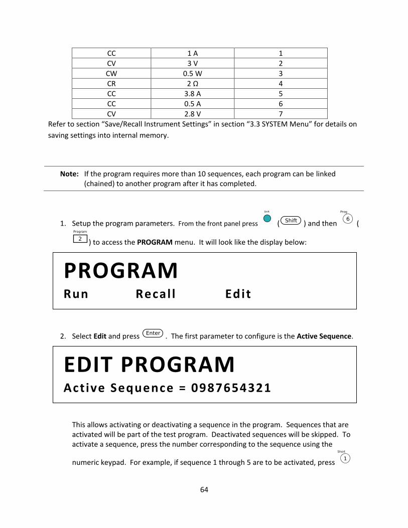
64
CC 1 A 1
CV 3 V 2
CW 0.5 W 3
CR 2 Ω 4
CC 3.8 A 5
CC 0.5 A 6
CV 2.8 V 7
Refer to section “Save/Recall Instrument Settings” in section “3.3 SYSTEM Menu” for details on
saving settings into internal memory.
Note: If the program requires more than 10 sequences, each program can be linked (chained) to another program after it has completed.
1. Setup the program parameters. From the front panel press ( ) and then (
) to access the PROGRAM menu. It will look like the display below:
2. Select Edit and press . The first parameter to configure is the Active Sequence.
This allows activating or deactivating a sequence in the program. Sequences that are activated will be part of the test program. Deactivated sequences will be skipped. To activate a sequence, press the number corresponding to the sequence using the
numeric keypad. For example, if sequence 1 through 5 are to be activated, press
EDIT PROGRAM Active Sequence = 0987654321
PROGRAM Run Recal l Edit
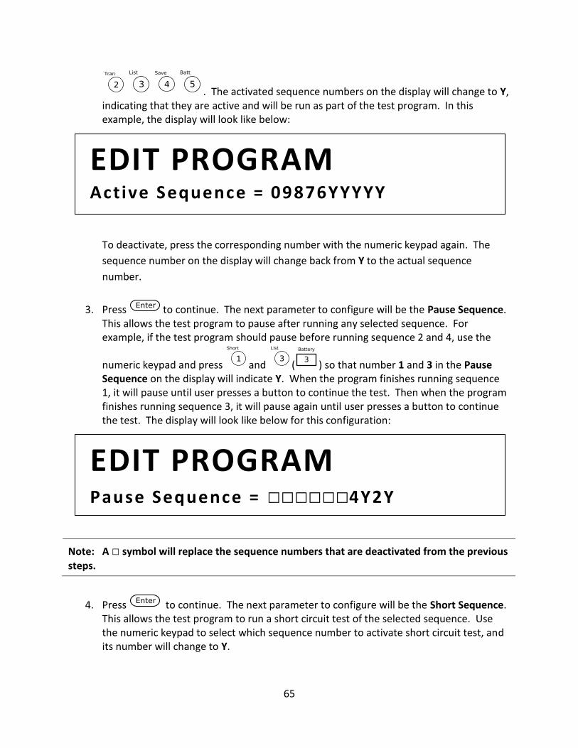
65
. The activated sequence numbers on the display will change to Y, indicating that they are active and will be run as part of the test program. In this example, the display will look like below:
To deactivate, press the corresponding number with the numeric keypad again. The
sequence number on the display will change back from Y to the actual sequence
number.
3. Press to continue. The next parameter to configure will be the Pause Sequence. This allows the test program to pause after running any selected sequence. For example, if the test program should pause before running sequence 2 and 4, use the
numeric keypad and press and ( ) so that number 1 and 3 in the Pause Sequence on the display will indicate Y. When the program finishes running sequence 1, it will pause until user presses a button to continue the test. Then when the program finishes running sequence 3, it will pause again until user presses a button to continue the test. The display will look like below for this configuration:
Note: A symbol will replace the sequence numbers that are deactivated from the previous
steps.
4. Press to continue. The next parameter to configure will be the Short Sequence. This allows the test program to run a short circuit test of the selected sequence. Use the numeric keypad to select which sequence number to activate short circuit test, and its number will change to Y.
EDIT PROGRAM Pause Sequence = 4Y2Y
EDIT PROGRAM Active Sequence = 09876YYYYY
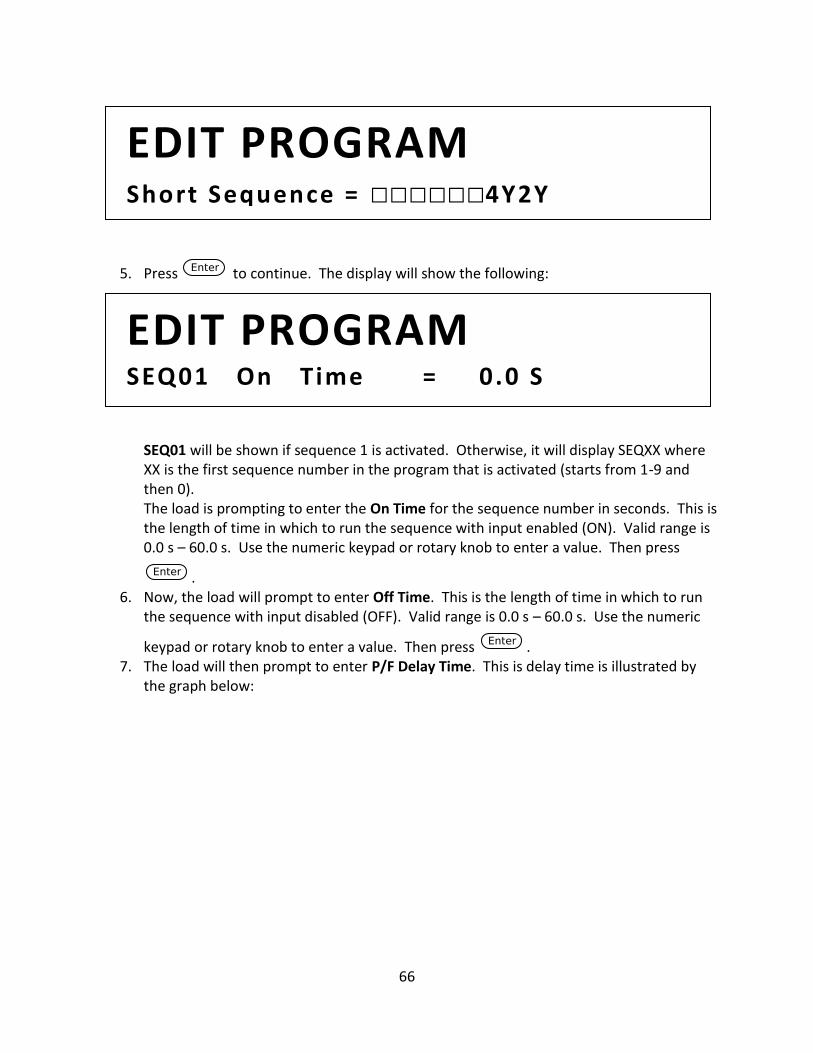
66
5. Press to continue. The display will show the following:
SEQ01 will be shown if sequence 1 is activated. Otherwise, it will display SEQXX where XX is the first sequence number in the program that is activated (starts from 1-9 and then 0). The load is prompting to enter the On Time for the sequence number in seconds. This is the length of time in which to run the sequence with input enabled (ON). Valid range is 0.0 s – 60.0 s. Use the numeric keypad or rotary knob to enter a value. Then press
. 6. Now, the load will prompt to enter Off Time. This is the length of time in which to run
the sequence with input disabled (OFF). Valid range is 0.0 s – 60.0 s. Use the numeric
keypad or rotary knob to enter a value. Then press . 7. The load will then prompt to enter P/F Delay Time. This is delay time is illustrated by
the graph below:
EDIT PROGRAM SEQ01 On T ime = 0 .0 S
EDIT PROGRAM Short Sequence = 4Y2Y
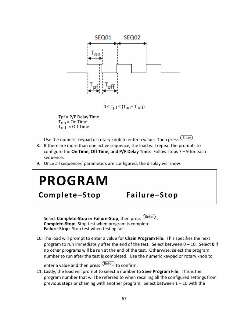
67
0 ≤ Tpf ≤ (Ton+ T off)
Tpf = P/F Delay Time Ton = On Time Toff = Off Time
Use the numeric keypad or rotary knob to enter a value. Then press . 8. If there are more than one active sequence, the load will repeat the prompts to
configure the On Time, Off Time, and P/F Delay Time. Follow steps 7 – 9 for each sequence.
9. Once all sequences’ parameters are configured, the display will show:
Select Complete-Stop or Failure-Stop, then press . Complete-Stop: Stop test when program is complete. Failure-Stop: Stop test when testing fails.
10. The load will prompt to enter a value for Chain Program File. This specifies the next program to run immediately after the end of the test. Select between 0 – 10. Select 0 if no other programs will be run at the end of the test. Otherwise, select the program number to run after the test is completed. Use the numeric keypad or rotary knob to
enter a value and then press to confirm. 11. Lastly, the load will prompt to select a number to Save Program File. This is the
program number that will be referred to when recalling all the configured settings from previous steps or chaining with another program. Select between 1 – 10 with the
PROGRAM Complete–Stop Fai lure–Stop
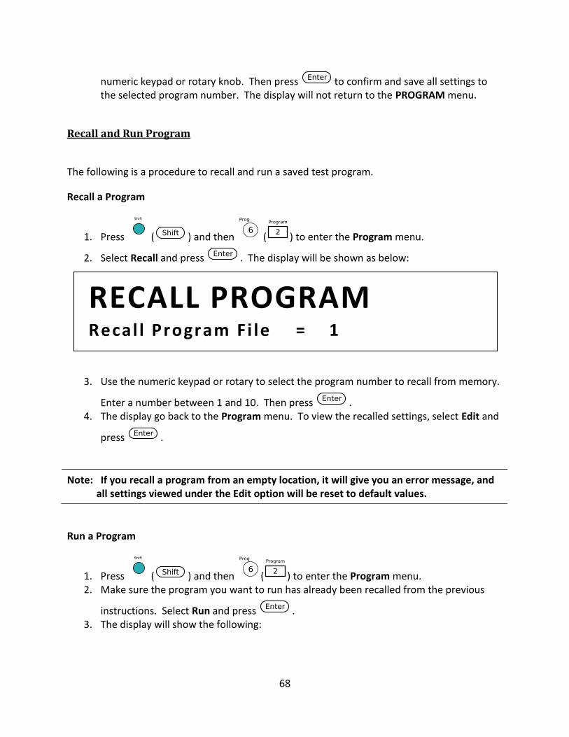
68
numeric keypad or rotary knob. Then press to confirm and save all settings to the selected program number. The display will not return to the PROGRAM menu.
Recall and Run Program
The following is a procedure to recall and run a saved test program.
Recall a Program
1. Press ( ) and then ( ) to enter the Program menu.
2. Select Recall and press . The display will be shown as below:
3. Use the numeric keypad or rotary to select the program number to recall from memory.
Enter a number between 1 and 10. Then press . 4. The display go back to the Program menu. To view the recalled settings, select Edit and
press .
Note: If you recall a program from an empty location, it will give you an error message, and all settings viewed under the Edit option will be reset to default values.
Run a Program
1. Press ( ) and then ( ) to enter the Program menu. 2. Make sure the program you want to run has already been recalled from the previous
instructions. Select Run and press . 3. The display will show the following:
RECALL PROGRAM Recal l Program Fi le = 1
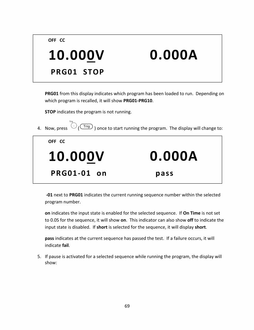
69
PRG01 from this display indicates which program has been loaded to run. Depending on
which program is recalled, it will show PRG01-PRG10.
STOP indicates the program is not running.
4. Now, press ( ) once to start running the program. The display will change to:
-01 next to PRG01 indicates the current running sequence number within the selected
program number.
on indicates the input state is enabled for the selected sequence. If On Time is not set
to 0.0S for the sequence, it will show on. This indicator can also show off to indicate the
input state is disabled. If short is selected for the sequence, it will display short.
pass indicates at the current sequence has passed the test. If a failure occurs, it will
indicate fail.
5. If pause is activated for a selected sequence while running the program, the display will show:
10.000V 0.000A PRG01-01 on pass
OFF CC
10.000V 0.000A PRG01 STOP
OFF CC
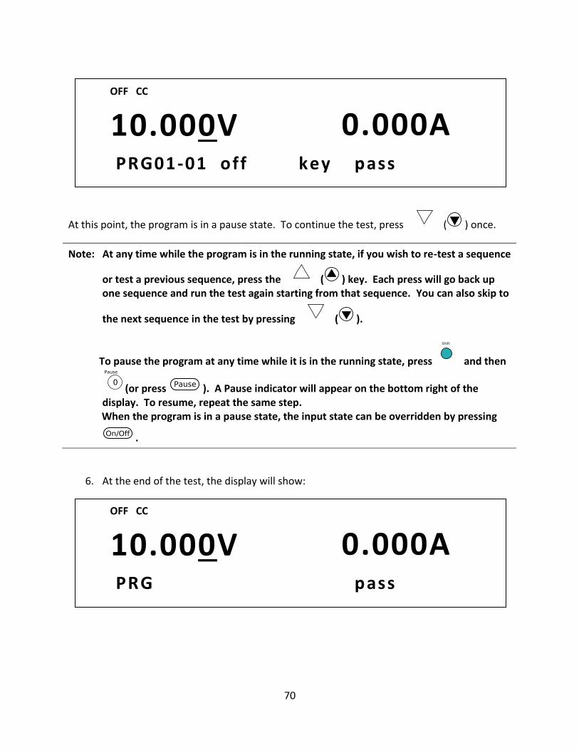
70
At this point, the program is in a pause state. To continue the test, press ( ) once.
Note: At any time while the program is in the running state, if you wish to re-test a sequence
or test a previous sequence, press the ( ) key. Each press will go back up one sequence and run the test again starting from that sequence. You can also skip to
the next sequence in the test by pressing ( ).
To pause the program at any time while it is in the running state, press and then
(or press ). A Pause indicator will appear on the bottom right of the display. To resume, repeat the same step.
When the program is in a pause state, the input state can be overridden by pressing
.
6. At the end of the test, the display will show:
10.000V 0.000A PRG pass
OFF CC
10.000V 0.000A PRG01-01 off key pass
OFF CC
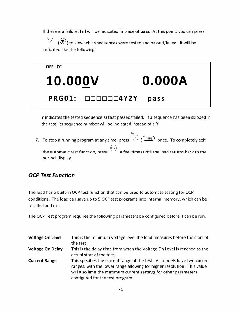
71
If there is a failure, fail will be indicated in place of pass. At this point, you can press
( ) to view which sequences were tested and passed/failed. It will be
indicated like the following:
Y indicates the tested sequence(s) that passed/failed. If a sequence has been skipped in
the test, its sequence number will be indicated instead of a Y.
7. To stop a running program at any time, press ( )once. To completely exit
the automatic test function, press a few times until the load returns back to the normal display.
OCP Test Function
The load has a built-in OCP test function that can be used to automate testing for OCP
conditions. The load can save up to 5 OCP test programs into internal memory, which can be
recalled and run.
The OCP Test program requires the following parameters be configured before it can be run.
Voltage On Level This is the minimum voltage level the load measures before the start of the test.
Voltage On Delay This is the delay time from when the Voltage On Level is reached to the actual start of the test.
Current Range This specifies the current range of the test. All models have two current ranges, with the lower range allowing for higher resolution. This value will also limit the maximum current settings for other parameters configured for the test program.
10.000V 0.000A PRG01: 4Y2Y pass
OFF CC
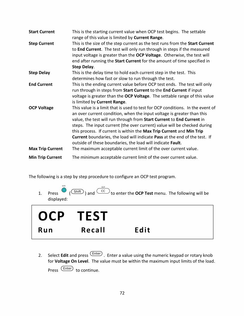
72
Start Current This is the starting current value when OCP test begins. The settable range of this value is limited by Current Range.
Step Current This is the size of the step current as the test runs from the Start Current to End Current. The test will only run through in steps if the measured input voltage is greater than the OCP Voltage. Otherwise, the test will end after running the Start Current for the amount of time specified in Step Delay.
Step Delay This is the delay time to hold each current step in the test. This determines how fast or slow to run through the test.
End Current This is the ending current value before OCP test ends. The test will only run through in steps from Start Current to the End Current if input voltage is greater than the OCP Voltage. The settable range of this value is limited by Current Range.
OCP Voltage This value is a limit that is used to test for OCP conditions. In the event of an over current condition, when the input voltage is greater than this value, the test will run through from Start Current to End Current in steps. The input current (the over current) value will be checked during this process. If current is within the Max Trip Current and Min Trip Current boundaries, the load will indicate Pass at the end of the test. If outside of these boundaries, the load will indicate Fault.
Max Trip Current The maximum acceptable current limit of the over current value.
Min Trip Current The minimum acceptable current limit of the over current value.
The following is a step by step procedure to configure an OCP test program.
1. Press ( ) and to enter the OCP Test menu. The following will be displayed:
2. Select Edit and press . Enter a value using the numeric keypad or rotary knob for Voltage On Level. The value must be within the maximum input limits of the load.
Press to continue.
OCP TEST Run Recal l Edit
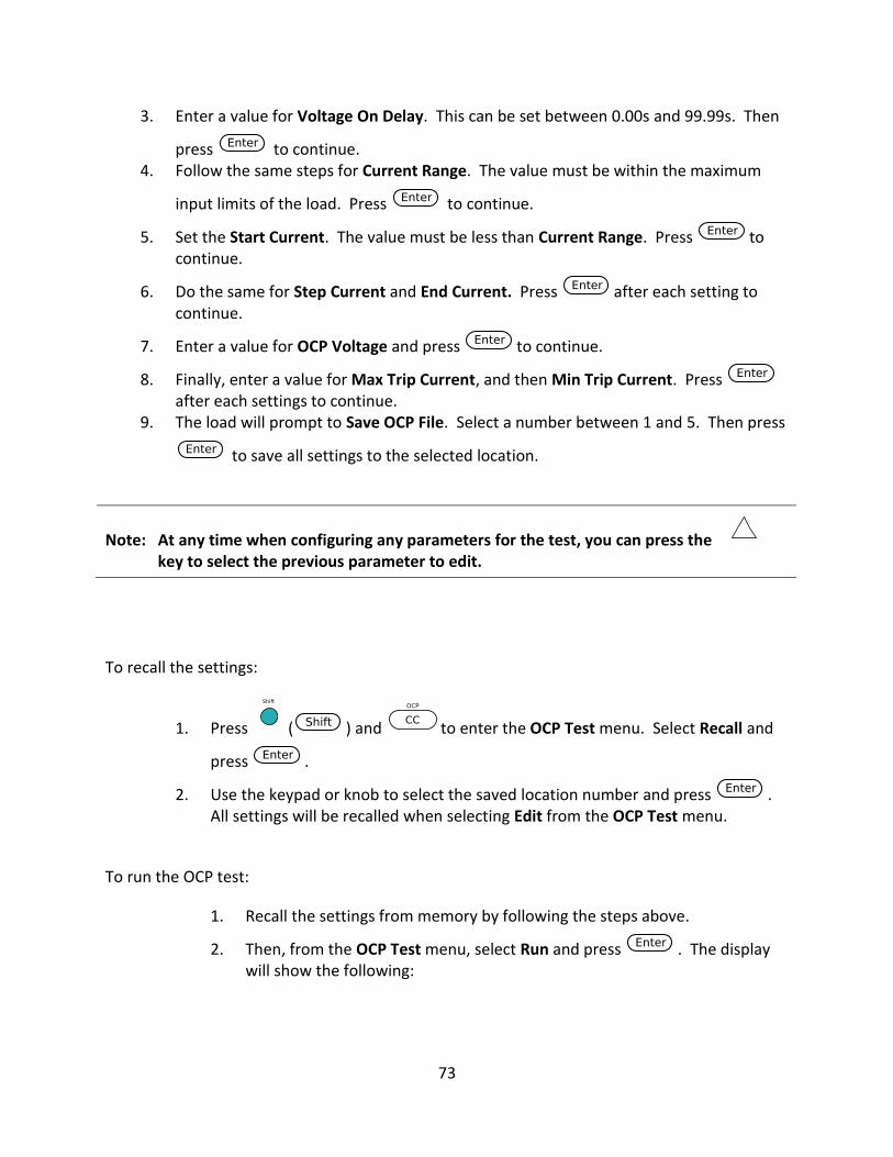
73
3. Enter a value for Voltage On Delay. This can be set between 0.00s and 99.99s. Then
press to continue. 4. Follow the same steps for Current Range. The value must be within the maximum
input limits of the load. Press to continue.
5. Set the Start Current. The value must be less than Current Range. Press to continue.
6. Do the same for Step Current and End Current. Press after each setting to continue.
7. Enter a value for OCP Voltage and press to continue.
8. Finally, enter a value for Max Trip Current, and then Min Trip Current. Press after each settings to continue.
9. The load will prompt to Save OCP File. Select a number between 1 and 5. Then press
to save all settings to the selected location.
Note: At any time when configuring any parameters for the test, you can press the key to select the previous parameter to edit.
To recall the settings:
1. Press ( ) and to enter the OCP Test menu. Select Recall and
press .
2. Use the keypad or knob to select the saved location number and press . All settings will be recalled when selecting Edit from the OCP Test menu.
To run the OCP test:
1. Recall the settings from memory by following the steps above.
2. Then, from the OCP Test menu, select Run and press . The display will show the following:
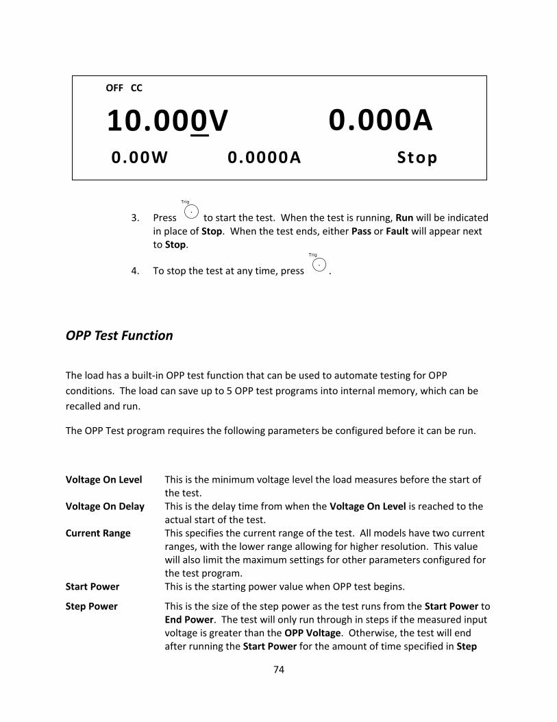
74
3. Press to start the test. When the test is running, Run will be indicated in place of Stop. When the test ends, either Pass or Fault will appear next to Stop.
4. To stop the test at any time, press .
OPP Test Function
The load has a built-in OPP test function that can be used to automate testing for OPP
conditions. The load can save up to 5 OPP test programs into internal memory, which can be
recalled and run.
The OPP Test program requires the following parameters be configured before it can be run.
Voltage On Level This is the minimum voltage level the load measures before the start of the test.
Voltage On Delay This is the delay time from when the Voltage On Level is reached to the actual start of the test.
Current Range This specifies the current range of the test. All models have two current ranges, with the lower range allowing for higher resolution. This value will also limit the maximum settings for other parameters configured for the test program.
Start Power This is the starting power value when OPP test begins.
Step Power This is the size of the step power as the test runs from the Start Power to End Power. The test will only run through in steps if the measured input voltage is greater than the OPP Voltage. Otherwise, the test will end after running the Start Power for the amount of time specified in Step
10.000V 0.000A 0.00W 0 .0000A Stop
OFF CC
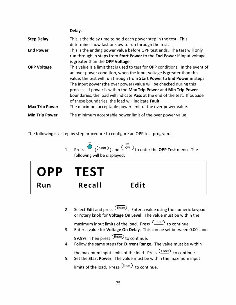
75
Delay.
Step Delay This is the delay time to hold each power step in the test. This determines how fast or slow to run through the test.
End Power This is the ending power value before OPP test ends. The test will only run through in steps from Start Power to the End Power if input voltage is greater than the OPP Voltage.
OPP Voltage This value is a limit that is used to test for OPP conditions. In the event of an over power condition, when the input voltage is greater than this value, the test will run through from Start Power to End Power in steps. The input power (the over power) value will be checked during this process. If power is within the Max Trip Power and Min Trip Power boundaries, the load will indicate Pass at the end of the test. If outside of these boundaries, the load will indicate Fault.
Max Trip Power The maximum acceptable power limit of the over power value.
Min Trip Power The minimum acceptable power limit of the over power value.
The following is a step by step procedure to configure an OPP test program.
1. Press ( ) and to enter the OPP Test menu. The following will be displayed:
2. Select Edit and press . Enter a value using the numeric keypad or rotary knob for Voltage On Level. The value must be within the
maximum input limits of the load. Press to continue. 3. Enter a value for Voltage On Delay. This can be set between 0.00s and
99.99s. Then press to continue. 4. Follow the same steps for Current Range. The value must be within
the maximum input limits of the load. Press to continue. 5. Set the Start Power. The value must be within the maximum input
limits of the load. Press to continue.
OPP TEST Run Recal l Edit
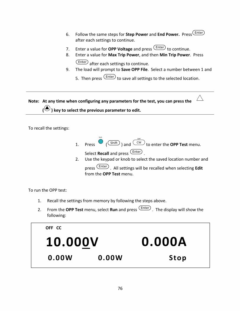
76
6. Follow the same steps for Step Power and End Power. Pressafter each settings to continue.
7. Enter a value for OPP Voltage and press to continue. 8. Enter a value for Max Trip Power, and then Min Trip Power. Press
after each settings to continue. 9. The load will prompt to Save OPP File. Select a number between 1 and
5. Then press to save all settings to the selected location.
Note: At any time when configuring any parameters for the test, you can press the
( ) key to select the previous parameter to edit.
To recall the settings:
1. Press ( ) and to enter the OPP Test menu.
Select Recall and press . 2. Use the keypad or knob to select the saved location number and
press . All settings will be recalled when selecting Edit from the OPP Test menu.
To run the OPP test:
1. Recall the settings from memory by following the steps above.
2. From the OPP Test menu, select Run and press . The display will show the following:
10.000V 0.000A 0.00W 0 .00W Stop
OFF CC
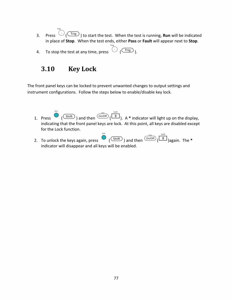
77
3. Press ( ) to start the test. When the test is running, Run will be indicated in place of Stop. When the test ends, either Pass or Fault will appear next to Stop.
4. To stop the test at any time, press ( ).
3.10 Key Lock
The front panel keys can be locked to prevent unwanted changes to output settings and
instrument configurations. Follow the steps below to enable/disable key lock.
1. Press ( ) and then ( ). A * indicator will light up on the display, indicating that the front panel keys are lock. At this point, all keys are disabled except for the Lock function.
2. To unlock the keys again, press ( ) and then ( )again. The * indicator will disappear and all keys will be enabled.
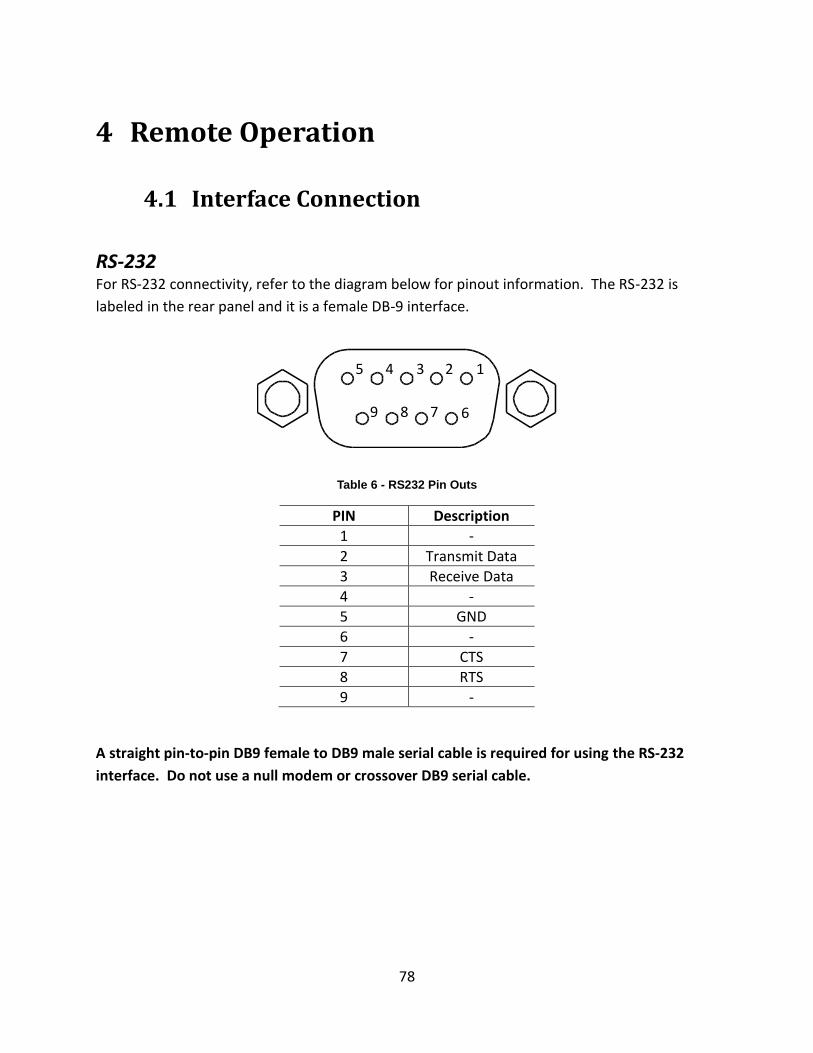
78
4 Remote Operation
4.1 Interface Connection
RS-232 For RS-232 connectivity, refer to the diagram below for pinout information. The RS-232 is
labeled in the rear panel and it is a female DB-9 interface.
Table 6 - RS232 Pin Outs
PIN Description
1 -
2 Transmit Data
3 Receive Data
4 -
5 GND
6 -
7 CTS
8 RTS
9 -
A straight pin-to-pin DB9 female to DB9 male serial cable is required for using the RS-232
interface. Do not use a null modem or crossover DB9 serial cable.
1 2 3 4 5
6 7 8 9
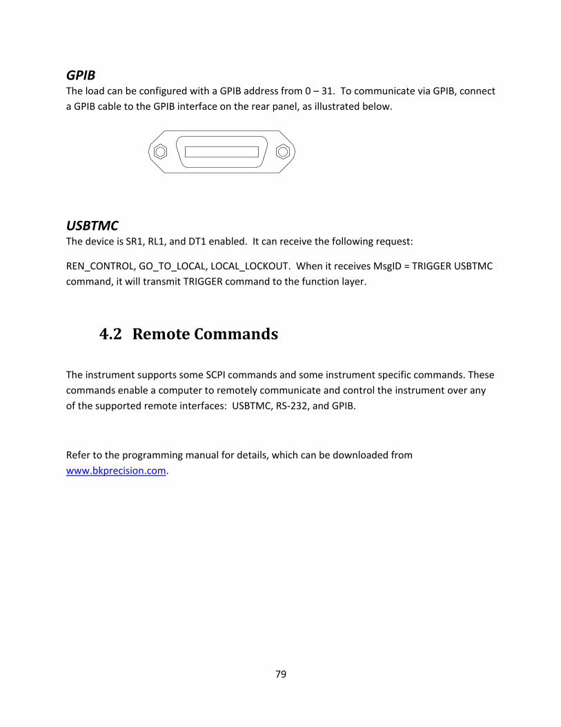
79
GPIB The load can be configured with a GPIB address from 0 – 31. To communicate via GPIB, connect
a GPIB cable to the GPIB interface on the rear panel, as illustrated below.
USBTMC The device is SR1, RL1, and DT1 enabled. It can receive the following request:
REN_CONTROL, GO_TO_LOCAL, LOCAL_LOCKOUT. When it receives MsgID = TRIGGER USBTMC
command, it will transmit TRIGGER command to the function layer.
4.2 Remote Commands
The instrument supports some SCPI commands and some instrument specific commands. These
commands enable a computer to remotely communicate and control the instrument over any
of the supported remote interfaces: USBTMC, RS-232, and GPIB.
Refer to the programming manual for details, which can be downloaded from
www.bkprecision.com.
80
5 Troubleshooting Guide
Below are some frequently asked questions and answers. Please check if any apply to your
instrument before contacting B&K Precision.
General Q: I cannot power up the instrument.
Check that the power cord is securely connected to the AC input and there is live power from
your electrical AC outlet.
Verify that the AC power coming from the mains have the correct voltage. The load can accept
a specific range of AC input voltages. Refer to section “2.1”.
Q: I cannot set power (in CW) or current (in CC) at the maximum rating.
4. Check the power and current Limits from the Protect menu within the CONFIG menu. Refer to section 3.4 for details.
Remote Control Q: I am trying to send the commands over USB/RS232, but it does not seem to respond.
Check that you are sending ASCII strings that are terminated with a CR (carriage return) and LF
(line feed) character.
For RS-232, check that the baud rate, parity, data bits, stop bit, and flow control settings match
with the settings configured on the software interface. To check these settings, go to the
SYSTEM menu and enter the Communication menu, and select RS-232.
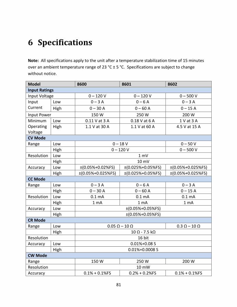
81
6 Specifications
Note: All specifications apply to the unit after a temperature stabilization time of 15 minutes
over an ambient temperature range of 23 °C ± 5 °C. Specifications are subject to change
without notice.
Model 8600 8601 8602
Input Ratings
Input Voltage 0 – 120 V 0 – 120 V 0 – 500 V
Input Current
Low 0 – 3 A 0 – 6 A 0 – 3 A
High 0 – 30 A 0 – 60 A 0 – 15 A
Input Power 150 W 250 W 200 W
Minimum Operating Voltage
Low 0.11 V at 3 A 0.18 V at 6 A 1 V at 3 A
High 1.1 V at 30 A 1.1 V at 60 A 4.5 V at 15 A
CV Mode
Range Low 0 – 18 V 0 – 50 V
High 0 – 120 V 0 – 500 V
Resolution Low 1 mV
High 10 mV
Accuracy Low ±(0.05%+0.02%FS) ±(0.025%+0.05%FS) ±(0.05%+0.025%FS)
High ±(0.05%+0.025%FS) ±(0.025%+0.05%FS) ±(0.05%+0.025%FS)
CC Mode
Range Low 0 – 3 A 0 – 6 A 0 – 3 A
High 0 – 30 A 0 – 60 A 0 – 15 A
Resolution Low 0.1 mA 0.1 mA 0.1 mA
High 1 mA 1 mA 1 mA
Accuracy Low ±(0.05%+0.05%FS)
High ±(0.05%+0.05%FS)
CR Mode
Range Low 0.05 Ω – 10 Ω 0.3 Ω – 10 Ω
High 10 Ω - 7.5 kΩ
Resolution 16 bit
Accuracy Low 0.01%+0.08 S
High 0.01%+0.0008 S
CW Mode
Range 150 W 250 W 200 W
Resolution 10 mW
Accuracy 0.1% + 0.1%FS 0.2% + 0.2%FS 0.1% + 0.1%FS
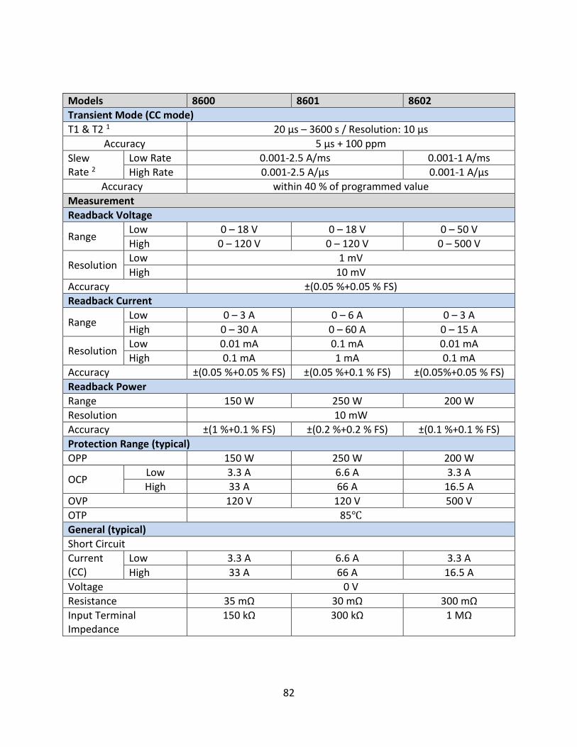
82
Models 8600 8601 8602
Transient Mode (CC mode)
T1 & T2 1 20 µs – 3600 s / Resolution: 10 µs
Accuracy 5 µs + 100 ppm
Slew Rate 2
Low Rate 0.001-2.5 A/ms 0.001-1 A/ms
High Rate 0.001-2.5 A/µs 0.001-1 A/µs
Accuracy within 40 % of programmed value
Measurement
Readback Voltage
Range Low 0 – 18 V 0 – 18 V 0 – 50 V
High 0 – 120 V 0 – 120 V 0 – 500 V
Resolution Low 1 mV
High 10 mV
Accuracy ±(0.05 %+0.05 % FS)
Readback Current
Range Low 0 – 3 A 0 – 6 A 0 – 3 A
High 0 – 30 A 0 – 60 A 0 – 15 A
Resolution Low 0.01 mA 0.1 mA 0.01 mA
High 0.1 mA 1 mA 0.1 mA
Accuracy ±(0.05 %+0.05 % FS) ±(0.05 %+0.1 % FS) ±(0.05%+0.05 % FS)
Readback Power
Range 150 W 250 W 200 W
Resolution 10 mW
Accuracy ±(1 %+0.1 % FS) ±(0.2 %+0.2 % FS) ±(0.1 %+0.1 % FS)
Protection Range (typical)
OPP 150 W 250 W 200 W
OCP Low 3.3 A 6.6 A 3.3 A
High 33 A 66 A 16.5 A
OVP 120 V 120 V 500 V
OTP 85
General (typical)
Short Circuit
Current (CC)
Low 3.3 A 6.6 A 3.3 A
High 33 A 66 A 16.5 A
Voltage 0 V
Resistance 35 mΩ 30 mΩ 300 mΩ
Input Terminal Impedance
150 kΩ 300 kΩ 1 MΩ
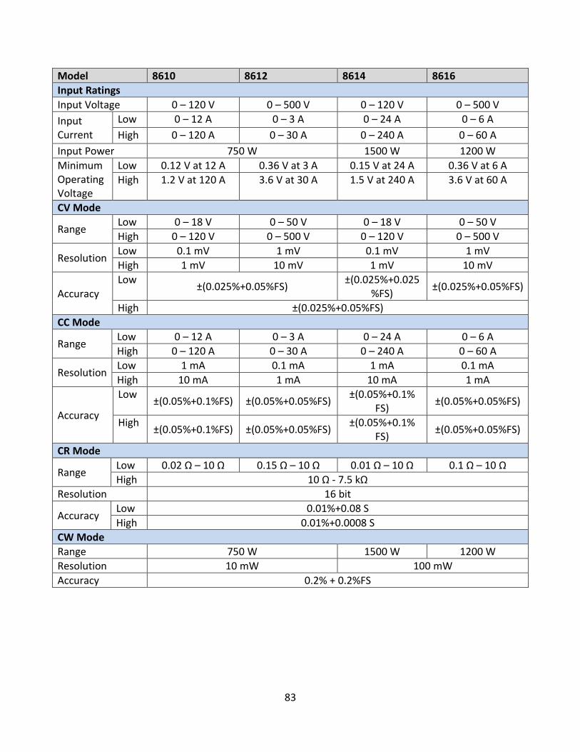
83
Model 8610 8612 8614 8616
Input Ratings
Input Voltage 0 – 120 V 0 – 500 V 0 – 120 V 0 – 500 V
Input Current
Low 0 – 12 A 0 – 3 A 0 – 24 A 0 – 6 A
High 0 – 120 A 0 – 30 A 0 – 240 A 0 – 60 A
Input Power 750 W 1500 W 1200 W
Minimum Operating Voltage
Low 0.12 V at 12 A 0.36 V at 3 A 0.15 V at 24 A 0.36 V at 6 A
High 1.2 V at 120 A 3.6 V at 30 A 1.5 V at 240 A 3.6 V at 60 A
CV Mode
Range Low 0 – 18 V 0 – 50 V 0 – 18 V 0 – 50 V
High 0 – 120 V 0 – 500 V 0 – 120 V 0 – 500 V
Resolution Low 0.1 mV 1 mV 0.1 mV 1 mV
High 1 mV 10 mV 1 mV 10 mV
Accuracy Low
±(0.025%+0.05%FS) ±(0.025%+0.025
%FS) ±(0.025%+0.05%FS)
High ±(0.025%+0.05%FS)
CC Mode
Range Low 0 – 12 A 0 – 3 A 0 – 24 A 0 – 6 A
High 0 – 120 A 0 – 30 A 0 – 240 A 0 – 60 A
Resolution Low 1 mA 0.1 mA 1 mA 0.1 mA
High 10 mA 1 mA 10 mA 1 mA
Accuracy
Low ±(0.05%+0.1%FS) ±(0.05%+0.05%FS)
±(0.05%+0.1% FS)
±(0.05%+0.05%FS)
High ±(0.05%+0.1%FS) ±(0.05%+0.05%FS)
±(0.05%+0.1% FS)
±(0.05%+0.05%FS)
CR Mode
Range Low 0.02 Ω – 10 Ω 0.15 Ω – 10 Ω 0.01 Ω – 10 Ω 0.1 Ω – 10 Ω
High 10 Ω - 7.5 kΩ
Resolution 16 bit
Accuracy Low 0.01%+0.08 S
High 0.01%+0.0008 S
CW Mode
Range 750 W 1500 W 1200 W
Resolution 10 mW 100 mW
Accuracy 0.2% + 0.2%FS
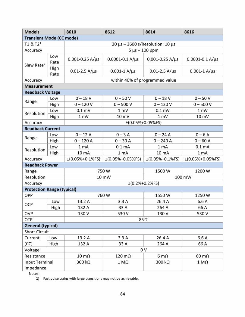
84
Models 8610 8612 8614 8616
Transient Mode (CC mode)
T1 & T21 20 µs – 3600 s/Resolution: 10 µs
Accuracy 5 µs + 100 ppm
Slew Rate2
Low Rate
0.001-0.25 A/µs 0.0001-0.1 A/µs 0.001-0.25 A/µs 0.0001-0.1 A/µs
High Rate
0.01-2.5 A/µs 0.001-1 A/µs 0.01-2.5 A/µs 0.001-1 A/µs
Accuracy within 40% of programmed value
Measurement
Readback Voltage
Range Low 0 – 18 V 0 – 50 V 0 – 18 V 0 – 50 V
High 0 – 120 V 0 – 500 V 0 – 120 V 0 – 500 V
Resolution Low 0.1 mV 1 mV 0.1 mV 1 mV
High 1 mV 10 mV 1 mV 10 mV
Accuracy ±(0.05%+0.05%FS)
Readback Current
Range Low 0 – 12 A 0 – 3 A 0 – 24 A 0 – 6 A
High 0 – 120 A 0 – 30 A 0 – 240 A 0 – 60 A
Resolution Low 1 mA 0.1 mA 1 mA 0.1 mA
High 10 mA 1 mA 10 mA 1 mA
Accuracy ±(0.05%+0.1%FS) ±(0.05%+0.05%FS) ±(0.05%+0.1%FS) ±(0.05%+0.05%FS)
Readback Power
Range 750 W 1500 W 1200 W
Resolution 10 mW 100 mW
Accuracy ±(0.2%+0.2%FS)
Protection Range (typical)
OPP 760 W 1550 W 1250 W
OCP Low 13.2 A 3.3 A 26.4 A 6.6 A
High 132 A 33 A 264 A 66 A
OVP 130 V 530 V 130 V 530 V
OTP 85
General (typical)
Short Circuit
Current (CC)
Low 13.2 A 3.3 A 26.4 A 6.6 A
High 132 A 33 A 264 A 66 A
Voltage 0 V
Resistance 10 mΩ 120 mΩ 6 mΩ 60 mΩ
Input Terminal Impedance
300 kΩ 1 MΩ 300 kΩ 1 MΩ
Notes: 1) Fast pulse trains with large transitions may not be achievable.
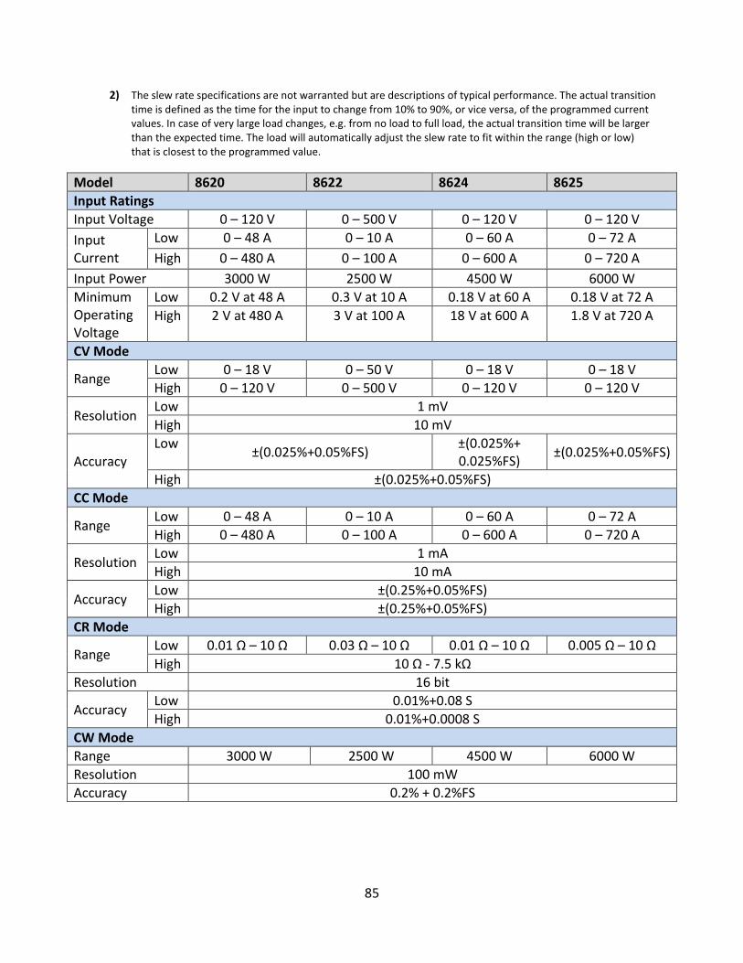
85
2) The slew rate specifications are not warranted but are descriptions of typical performance. The actual transition time is defined as the time for the input to change from 10% to 90%, or vice versa, of the programmed current values. In case of very large load changes, e.g. from no load to full load, the actual transition time will be larger than the expected time. The load will automatically adjust the slew rate to fit within the range (high or low) that is closest to the programmed value.
Model 8620 8622 8624 8625
Input Ratings
Input Voltage 0 – 120 V 0 – 500 V 0 – 120 V 0 – 120 V
Input Current
Low 0 – 48 A 0 – 10 A 0 – 60 A 0 – 72 A
High 0 – 480 A 0 – 100 A 0 – 600 A 0 – 720 A
Input Power 3000 W 2500 W 4500 W 6000 W
Minimum Operating Voltage
Low 0.2 V at 48 A 0.3 V at 10 A 0.18 V at 60 A 0.18 V at 72 A
High 2 V at 480 A 3 V at 100 A 18 V at 600 A 1.8 V at 720 A
CV Mode
Range Low 0 – 18 V 0 – 50 V 0 – 18 V 0 – 18 V
High 0 – 120 V 0 – 500 V 0 – 120 V 0 – 120 V
Resolution Low 1 mV
High 10 mV
Accuracy Low
±(0.025%+0.05%FS) ±(0.025%+ 0.025%FS)
±(0.025%+0.05%FS)
High ±(0.025%+0.05%FS)
CC Mode
Range Low 0 – 48 A 0 – 10 A 0 – 60 A 0 – 72 A
High 0 – 480 A 0 – 100 A 0 – 600 A 0 – 720 A
Resolution Low 1 mA
High 10 mA
Accuracy Low ±(0.25%+0.05%FS)
High ±(0.25%+0.05%FS)
CR Mode
Range Low 0.01 Ω – 10 Ω 0.03 Ω – 10 Ω 0.01 Ω – 10 Ω 0.005 Ω – 10 Ω
High 10 Ω - 7.5 kΩ
Resolution 16 bit
Accuracy Low 0.01%+0.08 S
High 0.01%+0.0008 S
CW Mode
Range 3000 W 2500 W 4500 W 6000 W
Resolution 100 mW
Accuracy 0.2% + 0.2%FS
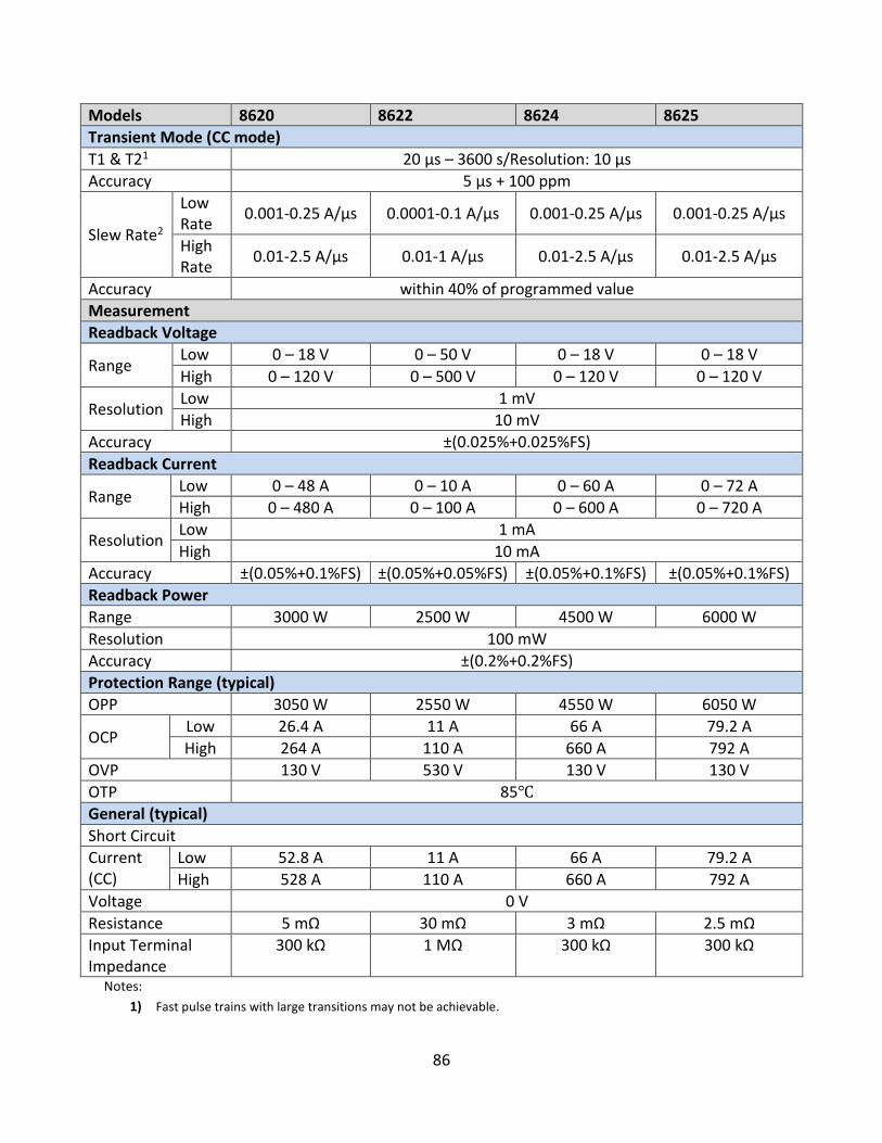
86
Models 8620 8622 8624 8625
Transient Mode (CC mode)
T1 & T21 20 µs – 3600 s/Resolution: 10 µs
Accuracy 5 µs + 100 ppm
Slew Rate2
Low Rate
0.001-0.25 A/µs 0.0001-0.1 A/µs 0.001-0.25 A/µs 0.001-0.25 A/µs
High Rate
0.01-2.5 A/µs 0.01-1 A/µs 0.01-2.5 A/µs 0.01-2.5 A/µs
Accuracy within 40% of programmed value
Measurement
Readback Voltage
Range Low 0 – 18 V 0 – 50 V 0 – 18 V 0 – 18 V
High 0 – 120 V 0 – 500 V 0 – 120 V 0 – 120 V
Resolution Low 1 mV
High 10 mV
Accuracy ±(0.025%+0.025%FS)
Readback Current
Range Low 0 – 48 A 0 – 10 A 0 – 60 A 0 – 72 A
High 0 – 480 A 0 – 100 A 0 – 600 A 0 – 720 A
Resolution Low 1 mA
High 10 mA
Accuracy ±(0.05%+0.1%FS) ±(0.05%+0.05%FS) ±(0.05%+0.1%FS) ±(0.05%+0.1%FS)
Readback Power
Range 3000 W 2500 W 4500 W 6000 W
Resolution 100 mW
Accuracy ±(0.2%+0.2%FS)
Protection Range (typical)
OPP 3050 W 2550 W 4550 W 6050 W
OCP Low 26.4 A 11 A 66 A 79.2 A
High 264 A 110 A 660 A 792 A
OVP 130 V 530 V 130 V 130 V
OTP 85
General (typical)
Short Circuit
Current (CC)
Low 52.8 A 11 A 66 A 79.2 A
High 528 A 110 A 660 A 792 A
Voltage 0 V
Resistance 5 mΩ 30 mΩ 3 mΩ 2.5 mΩ
Input Terminal Impedance
300 kΩ 1 MΩ 300 kΩ 300 kΩ
Notes:
1) Fast pulse trains with large transitions may not be achievable.
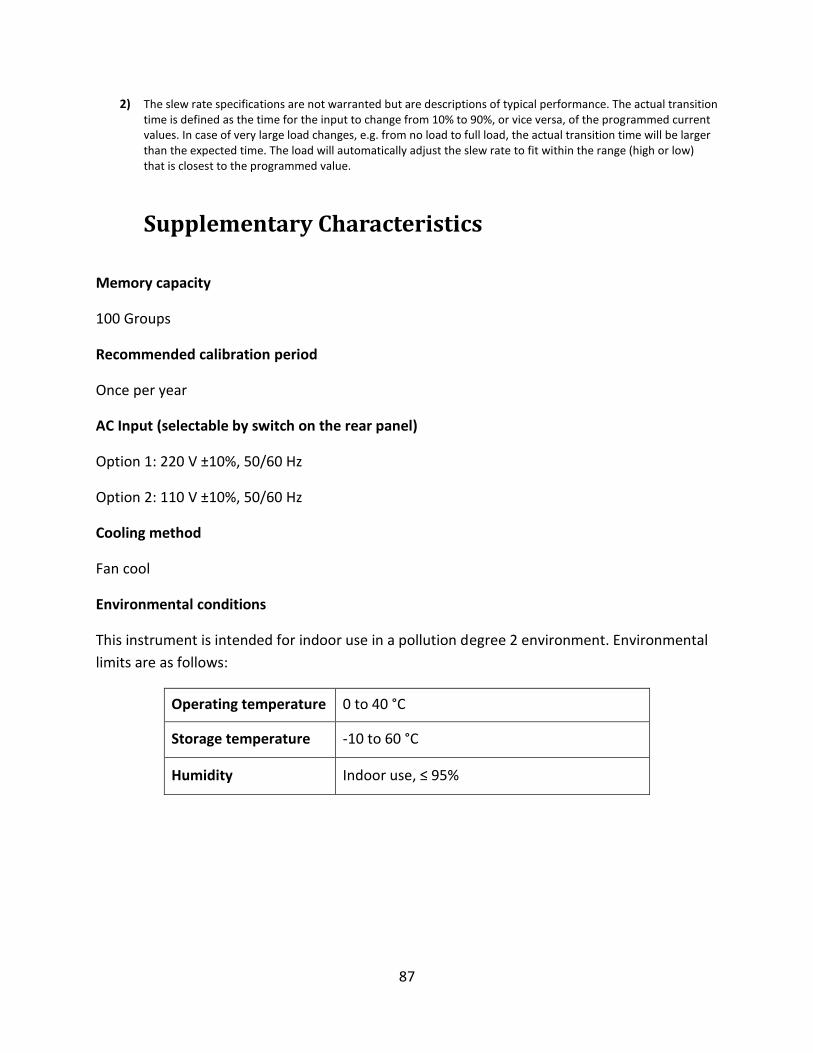
87
2) The slew rate specifications are not warranted but are descriptions of typical performance. The actual transition time is defined as the time for the input to change from 10% to 90%, or vice versa, of the programmed current values. In case of very large load changes, e.g. from no load to full load, the actual transition time will be larger than the expected time. The load will automatically adjust the slew rate to fit within the range (high or low) that is closest to the programmed value.
Supplementary Characteristics
Memory capacity
100 Groups
Recommended calibration period
Once per year
AC Input (selectable by switch on the rear panel)
Option 1: 220 V ±10%, 50/60 Hz
Option 2: 110 V ±10%, 50/60 Hz
Cooling method
Fan cool
Environmental conditions
This instrument is intended for indoor use in a pollution degree 2 environment. Environmental
limits are as follows:
Operating temperature 0 to 40 °C
Storage temperature -10 to 60 °C
Humidity Indoor use, ≤ 95%
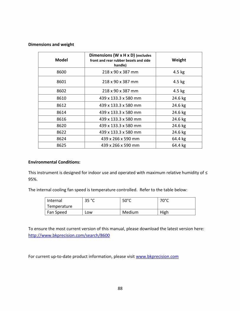
88
Dimensions and weight
Model Dimensions (W x H x D) (excludes
front and rear rubber bezels and side handle)
Weight
8600 218 x 90 x 387 mm 4.5 kg
8601 218 x 90 x 387 mm 4.5 kg
8602 218 x 90 x 387 mm 4.5 kg
8610 439 x 133.3 x 580 mm 24.6 kg
8612 439 x 133.3 x 580 mm 24.6 kg
8614 439 x 133.3 x 580 mm 24.6 kg
8616 439 x 133.3 x 580 mm 24.6 kg
8620 439 x 133.3 x 580 mm 24.6 kg
8622 439 x 133.3 x 580 mm 24.6 kg
8624 439 x 266 x 590 mm 64.4 kg
8625 439 x 266 x 590 mm 64.4 kg
Environmental Conditions:
This instrument is designed for indoor use and operated with maximum relative humidity of ≤
95%.
The internal cooling fan speed is temperature controlled. Refer to the table below:
Internal Temperature
35 °C 50°C 70°C
Fan Speed Low Medium High
To ensure the most current version of this manual, please download the latest version here:
http://www.bkprecision.com/search/8600
For current up-to-date product information, please visit www.bkprecision.com
89
7 Calibration
It is recommended that the instrument be returned to B&K Precision for service and periodic
calibration to ensure the instrument is performing within its specifications.
B&K Precision recommends calibrating the instrument once per year.

90
Index
AC input, 12 Automatic Test, 21, 24, 25, 27, 32, 61 Constant Current, 20 Constant Power, 25 Constant Resistance, 24 Constant Voltage, 23 Firmware Version, 17 Fuse, 13 Key Lock, 77 line voltage input, 12 List mode, 56
Menu, 18 Remote sense, 47 Restore Factory Default, 28 RMT, 35 Self Test, 15 Self-test, 15 Short, 50 System Menu, 18 Transient operation, 51 Trigger Source, 30 Von Latch, 37

SERVICE INFORMATION
Warranty Service: Please go to the support and service section on our website at www.bkprecision.com to obtain a RMA #.
Return the product in the original packaging with proof of purchase to the address below. Clearly state on the RMA the
performance problem and return any leads, probes, connectors and accessories that you are using with the device. Non-Warranty Service: Please go to the support and service section on our website at www.bkprecision.com to obtain a RMA
#. Return the product in the original packaging to the address below. Clearly state on the RMA the performance problem and
return any leads, probes, connectors and accessories that you are using with the device. Customers not on an open account
must include payment in the form of a money order or credit card. For the most current repair charges please refer to the
service and support section on our website.
Return all merchandise to B&K Precision Corp. with prepaid shipping. The flat-rate repair charge for Non-Warranty Service does
not include return shipping. Return shipping to locations in North America is included for Warranty Service. For overnight
shipments and non-North American shipping fees please contact B&K Precision Corp.
B&K Precision Corp.
22820 Savi Ranch Parkway
Yorba Linda, CA 92887
www.bkprecision.com
714-921-9095
Include with the returned instrument your complete return shipping address, contact name, phone number and description
of problem.

LIMITED THREE-YEAR WARRANTY
B&K Precision Corp. warrants to the original purchaser that its products and the component parts thereof, will be free from
defects in workmanship and materials for a period of three years from date of purchase.
B&K Precision Corp. will, without charge, repair or replace, at its option, defective product or component parts. Returned
product must be accompanied by proof of the purchase date in the form of a sales receipt.
To help us better serve you, please complete the warranty registration for your new instrument via our website
www.bkprecision.com
Exclusions: This warranty does not apply in the event of misuse or abuse of the product or as a result of unauthorized
alterations or repairs. The warranty is void if the serial number is altered, defaced or removed.
B&K Precision Corp. shall not be liable for any consequential damages, including without limitation damages resulting from loss
of use. Some states do not allow limitations of incidental or consequential damages. So the above limitation or exclusion may
not apply to you.
This warranty gives you specific rights and you may have other rights, which vary from state-to-state.
B&K Precision Corp.
22820 Savi Ranch Parkway
Yorba Linda, CA 92887
www.bkprecision.com
714-921-9095

22820 Savi Ranch Parkway
Yorba Linda, CA 92887
www.bkprecision.com
© 2017 B&K Precision Corp.
Printed in China v072017