Embed Size (px)
Citation preview
ROBERT H. WAGER COMPANY Installation, Operation and Maintenance Guide
Models1500/1500-MC
1700/1750
M O D E L S 1 5 0 0 / 1 5 0 0 - M C / 1 7 0 0 / 1 7 5 0
Installation, Operation and Maintenance Guide
Robert H. Wager Company, Inc. 570 Montroyal Road • Forum Pkwy
Rural Hall, NC 27045 Phone 336.969.6909 • Fax 336.969-6375
Table of Contents INSTALLATION
MODELS 1500/1500-MC ........................................................1Mounting Special Instructions
MODELS 1700/1750 ................................................................2 Mounting
Special Instructions
OPERATION MODELS 1500/1500-MC ........................................................3MODELS 1700/1750 ................................................................4
MAINTENANCE MODELS 1500/1500-MC ........................................................5
Replacement of Spare Parts
CleaningMODELS 1700/1750 ................................................................6
Replacement of Spare Parts Cleaning
REFERENCES Technical Drawings.................................................................8
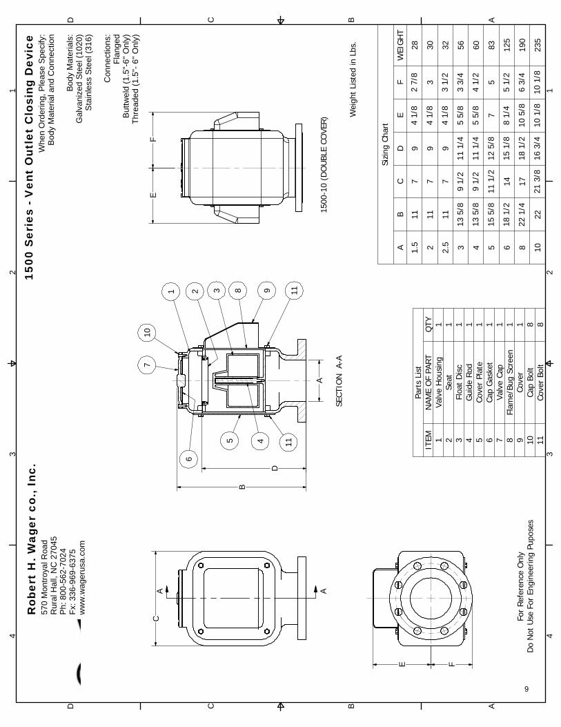
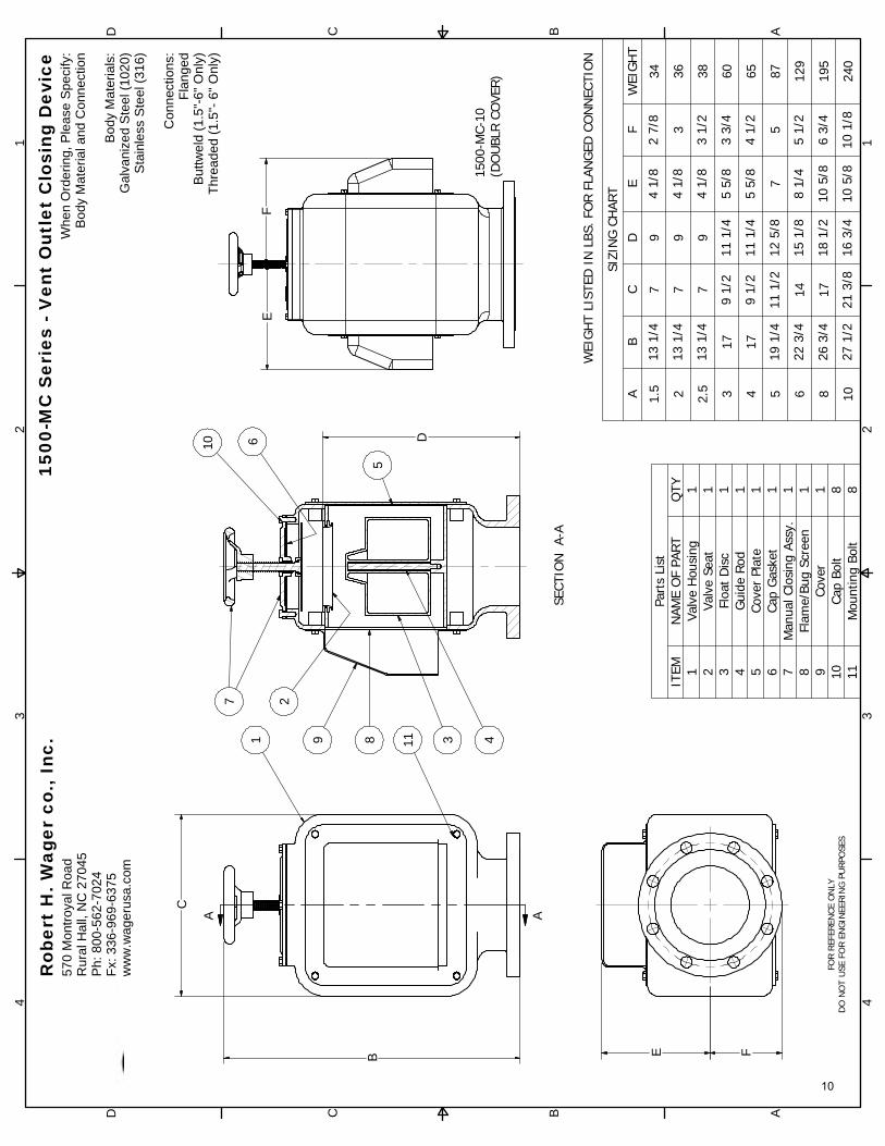
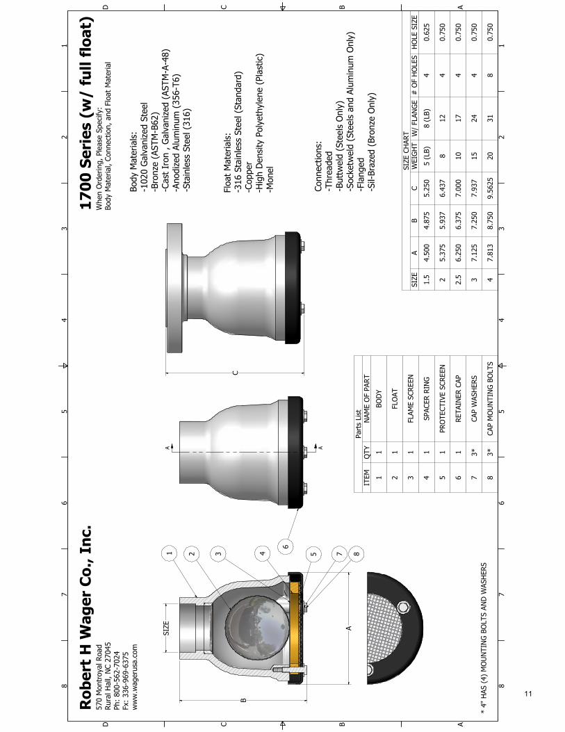
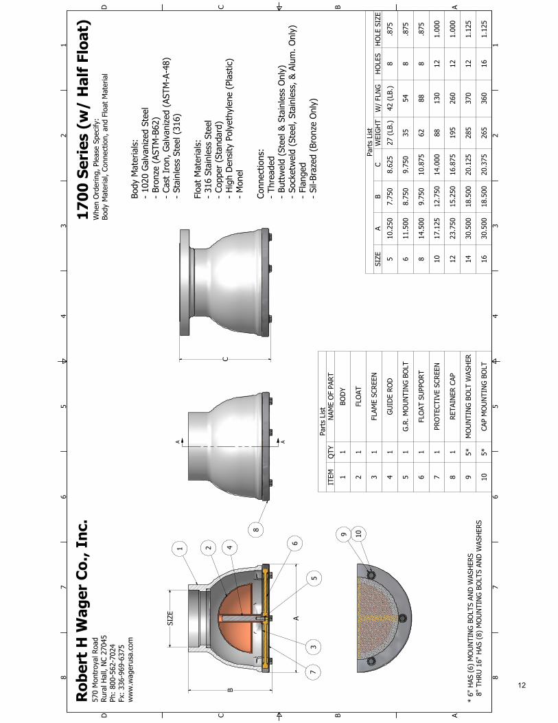
MODEL 1500 MODEL 1500-MC MODEL 1700 (FULL FLOAT – SIZES 1.5”-4”) MODEL 1700 (HALF FLOAT – SIZES 5”-12”) MODEL 1750 (FULL FLOAT – SIZES 1.5”-4”) MODEL 1750 (HALF FLOAT – SIZES 5”-12”)
ADDITIONAL PRODUCTS
I N S T A L L A T I O N , O P E R A T I O N A N D M A I N T E N A N C E
Installation Mounting (1500/1500-MC)
The 1500 and 1500-MC Series Vent Outlet Closing Devices are designed to be installed (mounted) in the vertical position.
Model 1500-MC will be shipped in the closed position. THE CLOSING DEVICE MUST BE IN THE OPEN POSITION FOR INTENDED VENTING OPERATION. (See “Operation” section of this manual for details)
Installing Flanged Connections – Vent Closing Devices come standard with an ANSI B16.5, 150 lb. slip-on type, raised face flanges (or Equivalent). All mounting hardware should be suitable for use per industry standards for 150 lb. piping systems. It is recommended the bolts be inserted from the bottom of the mating flange because of the limited area between the valve flange and the bottom of the housing. (Mating Flange, Mounting Bolts, Nuts, and Gaskets NOT INCLUDED)
Installing Buttweld Connections – Vent Closing Devices can be purchased with buttweld end connections as an alternative option. ANSI B16.25 welding procedures or industry acceptable standards should be followed. Buttweld end connections are consistent with schedule 40 specifications.
Installing Threaded Connections – Vent Closing Devices can also be supplied with a threaded connection. All threaded connections are Internal NPT (ANSI/ASME B1.20.1-1983, R1992). All thread sealants should be suitable for use per industry standards (NOT INCLUDED).
Special Instructions
During the installation, make sure that there are no obstructions blocking the cover or the accessibility or range of operation of the Manual Closing Device. (1500-MC)
If the Vent Outlet Closing Devices are to be painted after installation, make sure not to paint any part of the Flame/Bug Screen or the Valve Stem on the Manual Closing Assembly (1500-MC). Painting over these areas will prevent proper operation and venting capacity of the Vent Outlet Closing Device.
1
Mounting (1700/1750)
The 1700 and 1750 Series Vent Outlet Closing Devices are designed to be installed (mounted) in the Inverted position. (On a “Gooseneck”)
Model 1750 will be shipped in the closed position. THE CLOSING DEVICE MUST BE IN THE OPEN POSITION FOR INTENDED VENTING OPERATION. (See “Operation” section of this manual for details)
Installing Flanged Connections – Carbon/Galvanized/Stainless Steel Vent Closing Devices come standard with ANSI B16.5, 150 lb. slip-on type, raised face flanges. Bronze and Aluminum Vent Closing Devices are machined to a flat face, 150 lb. equivalent. All mounting hardware should be suitable for use per industry standards for 150 lb. piping systems. It is recommended the bolts be inserted from the top of the mating flange because of the limited area between the valve flange and the bottom of the housing. (Mating Flange, Mounting Bolts, Nuts, and Gaskets NOT INCLUDED)
Installing Buttweld Connections – Vent Closing Devices can be purchased with buttweld end connections as an alternative option. ANSI B16.25 welding procedures or industry acceptable standards should be followed. Buttweld end connections are consistent with schedule 40 specifications.
Installing Threaded Connections – Vent Closing Devices can also be supplied with a threaded connection. All threaded connections are Internal NPT (ANSI/ASME B1.20.1-1983, R1992). All thread sealants should be suitable for use per industry standards (NOT INCLUDED).
Special Instructions
During the installation, make sure that there are no obstructions blocking the cover or the accessibility or range of operation of the Manual Closing Device (Model 1750).
If the Vent Outlet Closing Devices are to be painted after installation, make sure not to paint any part of the Flame/Bug Screen or the Toggle Bolt Assembly on the Manual Closing Device (1750). Painting over these areas will prevent proper operation and venting capacity of the Vent Outlet Closing Device.
2
Operation All series of Vent Outlet Closing Devices are designed to prevent the ingress of liquid into the vented area or system. These vents are normally open, and close automatically when liquid levels reach the float, in turn, sealing the vent outlet. However, the 1500-MC and the 1750 Series Vent Outlet Closing Devices are designed to be closed manually when required.
Opening and Closing Manually (1500-MC)
The Series 1500-MC Vent Closing Devices are shipped in the CLOSED position. For proper ventilation during its working cycles, the valve must remain in the OPEN position. (Note: These valves are design to be watertight while in the closed position)
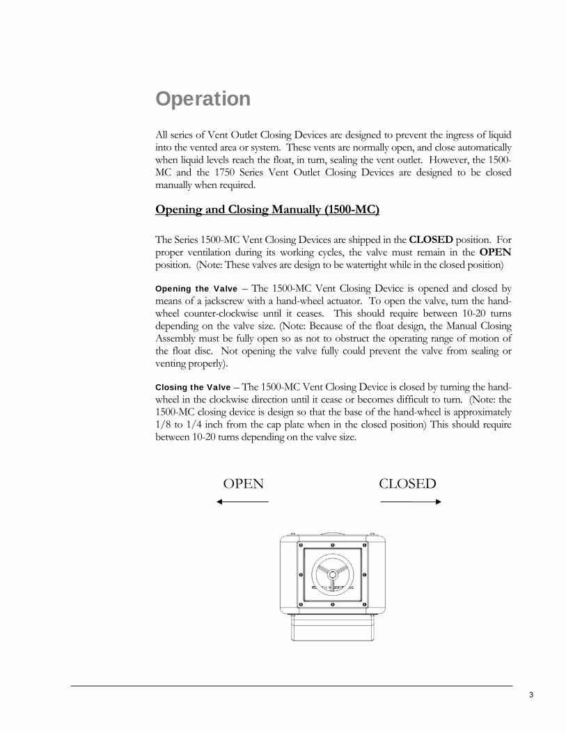
Opening the Valve – The 1500-MC Vent Closing Device is opened and closed by means of a jackscrew with a hand-wheel actuator. To open the valve, turn the hand-wheel counter-clockwise until it ceases. This should require between 10-20 turns depending on the valve size. (Note: Because of the float design, the Manual Closing Assembly must be fully open so as not to obstruct the operating range of motion of the float disc. Not opening the valve fully could prevent the valve from sealing or venting properly).
Closing the Valve – The 1500-MC Vent Closing Device is closed by turning the hand-wheel in the clockwise direction until it cease or becomes difficult to turn. (Note: the 1500-MC closing device is design so that the base of the hand-wheel is approximately 1/8 to 1/4 inch from the cap plate when in the closed position) This should require between 10-20 turns depending on the valve size.
OPEN CLOSED
3
Opening and Closing Manually (1750)
The Series 1750 Vent Closing Devices are shipped in the CLOSED position. For proper ventilation during its working cycles, the valve must remain in the OPEN position. (Note: These valves are designed to be spray resistant in the closed position.)
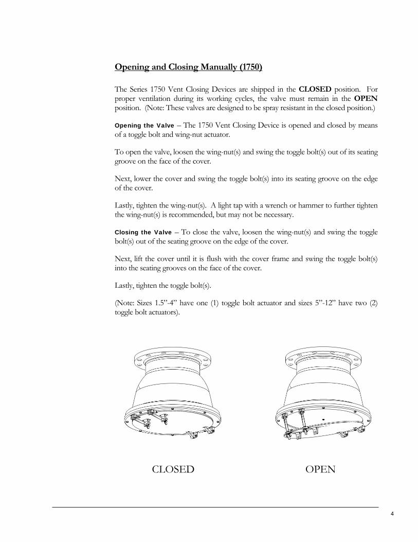
Opening the Valve – The 1750 Vent Closing Device is opened and closed by means of a toggle bolt and wing-nut actuator.
To open the valve, loosen the wing-nut(s) and swing the toggle bolt(s) out of its seating groove on the face of the cover.
Next, lower the cover and swing the toggle bolt(s) into its seating groove on the edge of the cover.
Lastly, tighten the wing-nut(s). A light tap with a wrench or hammer to further tighten the wing-nut(s) is recommended, but may not be necessary.
Closing the Valve – To close the valve, loosen the wing-nut(s) and swing the toggle bolt(s) out of the seating groove on the edge of the cover.
Next, lift the cover until it is flush with the cover frame and swing the toggle bolt(s) into the seating grooves on the face of the cover.
Lastly, tighten the toggle bolt(s).
(Note: Sizes 1.5”-4” have one (1) toggle bolt actuator and sizes 5”-12” have two (2) toggle bolt actuators).
CLOSED OPEN
4
Maintenance Replacement of Spare Parts and Cleaning (1500/1500-MC)
(Uninstalling the Vent Outlet Closing Devices prior to the replacement of spare parts is optional)
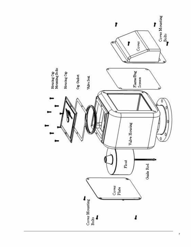
Accessing Seat and Inner Housing – To access the Seat and clean the inner housing, loosen the Cap Bolts and remove the Cap Plate. (Remove the manual Closing Device Assembly on the 1500-MC model) The Seat is a grommet style insert that can be removed simply by pulling it from the inner housing. (The Seat lies directly below the Cap Plate or Manual Closing Device Assembly) Remove any debris or media that have accumulated between the inner and outer housing.
Accessing the Float and Guide Rod Only – To access the Float and Guide Rod only, remove four (4) mounting bolts on the Cover Plate. (Secure plate with hand before removing the last bolt) The Float and Guide Rod can be removed by unscrewing the Guide Rod from its base. To re-install, place the float on the Guide Rod prior to screwing the Guide Rod into the base.
Accessing the Cover and Flame/Bug Screen – To access the Cover ad Flame/Bug Screen, remove four (4) mounting bolts from the Cover. (Secure Cover with Hand before removing the last bolt) Cover and Screen will fall once bolts are removed. (The Float and the Guide Rod can also be accessed by removing the Cover and Flame/Bug Screen.)
It is recommended that All Vent Outlet Closing Assemblies be cleaned and inspected every six months, although this is not required by the manufacturer. Upon inspection, all spare parts that are damaged or worn should be replaced to ensure proper valve function. (Replacement parts are defined as any part excluding the Closing Device Housing) See page 7.
5
Replacement of Spare Parts and cleaning (1700/1750)
(Uninstalling the Vent Outlet Closing Devices prior to the replacement of spare parts is recommended)
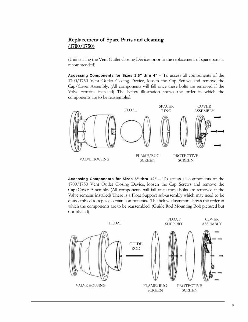
Accessing Components for Sizes 1.5” thru 4” – To access all components of the 1700/1750 Vent Outlet Closing Device, loosen the Cap Screws and remove the Cap/Cover Assembly. (All components will fall once these bolts are removed if the Valve remains installed) The below illustration shows the order in which the components are to be reassembled.
VALVE HOUSING
FLOAT
FLAME/BUG SCREEN
SPACER RING
PROTECTIVE SCREEN
COVER ASSEMBLY
Accessing Components for Sizes 5” thru 12” – To access all components of the 1700/1750 Vent Outlet Closing Device, loosen the Cap Screws and remove the Cap/Cover Assembly. (All components will fall once these bolts are removed if the Valve remains installed) There is a Float Support sub-assembly which may need to be disassembled to replace certain components. The below illustration shows the order in which the components are to be reassembled. (Guide Rod Mounting Bolt pictured but not labeled)
VALVE HOUSING
FLOAT
FLAME/BUG SCREEN
FLOAT SUPPORT
PROTECTIVESCREEN
COVER ASSEMBLY
GUIDEROD
6
7
M O D E L S 1 5 0 0 / 1 5 0 0 - M C / 1 7 0 0 / 1 7 5 0
References
Technical Drawings
8
SECT
ION
A-
A
1 1
2 2
3 3
4 4
AA
BB
CC
DD
A A
Part
s Li
stQ
TYN
AME
OF
PART
ITEM
1Va
lve
Hou
sing
11
Seat
21
Floa
t D
isc
31
Gui
de R
od4
1Co
ver
Plat
e5
1Ca
p G
aske
t6
1Va
lve
Cap
71
Flam
e/Bu
g Sc
reen
81
Cove
r9
8Ca
p Bo
lt10
8Co
ver
Bolt
11
Sizi
ng C
hart
AB
CD
EF
WEI
GH
T
1.5
117
94
1/8
2 7/
828
211
79
4 1/
83
30
2.5
117
94
1/8
3 1/
232
313
5/8
9 1/
211
1/4
5 5/
83
3/4
56
413
5/8
9 1/
211
1/4
5 5/
84
1/2
60
515
5/8
11 1
/212
5/8
75
83
618
1/2
1415
1/8
8 1/
45
1/2
125
822
1/4
1718
1/2
10 5
/86
3/4
190
1022
21 3
/816
3/4
10 1
/810
1/8
235
A
B
D
C
FE
1 2 3 8 945
6
710
1111
EF
1500
-10
(DO
UBL
E CO
VER
)
1500
Ser
ies
- Ven
t O
utle
t C
losi
ng D
evic
eW
hen
Ord
erin
g, P
leas
e S
peci
fy:
Bod
y M
ater
ial a
nd C
onne
ctio
n Bo
dy M
ater
ials
:G
alva
nize
d S
teel
(102
0)S
tain
less
Ste
el (3
16)
Con
nect
ions
:Fl
ange
dB
uttw
eld
(1.5
"-6"
Onl
y)Th
read
ed (1
.5"-
6" O
nly)
Wei
ght
List
ed in
Lbs
.
Rob
ert
H. W
ager
co.
, Inc
.57
0 M
ontro
yal R
oad
Rur
al H
all,
NC
270
45P
h: 8
00-5
62-7
024
Fx: 3
36-9
69-6
375
ww
w.w
ager
usa.
com
For
Ref
eren
ce O
nly
Do
Not
Use
For
Eng
inee
ring
Pupo
ses
9
SECT
ION
A-
A
1 1
2 2
3 3
4 4
AA
BB
CC
DD
A A
Part
s Li
stQ
TYN
AME
OF
PART
ITEM
1Va
lve
Hou
sing
11
Valv
e Se
at2
1Fl
oat
Dis
c3
1G
uide
Rod
41
Cove
r Pl
ate
51
Cap
Gas
ket
61
Man
ual C
losi
ng A
ssy.
71
Flam
e/Bu
g Sc
reen
81
Cove
r9
8Ca
p Bo
lt10
8M
ount
ing
Bolt
11
1500
-MC
Ser
ies
- Ven
t O
utle
t C
losi
ng D
evic
eW
hen
Ord
erin
g, P
leas
e Sp
ecify
:B
ody
Mat
eria
l and
Con
nect
ion
Bod
y M
ater
ials
:G
alva
nize
d S
teel
(102
0)S
tain
less
Ste
el (3
16)
Con
nect
ions
:Fl
ange
dB
uttw
eld
(1.5
"-6"
Onl
y)Th
read
ed (1
.5"-
6" O
nly)
Rob
ert
H. W
ager
co.
, Inc
.57
0 M
ontro
yal R
oad
Rur
al H
all,
NC
270
45P
h: 8
00-5
62-7
024
Fx: 3
36-9
69-6
375
ww
w.w
ager
usa.
com
FOR
REF
EREN
CE O
NLY
DO
NO
T U
SE F
OR
ENG
INEE
RIN
G P
URP
OSE
S
C
B E F
D
1 9 8
2
6
11 3 4
7
10
5
SIZI
NG
CH
ART
AB
CD
EF
WEI
GH
T
1.5
13 1
/47
94
1/8
2 7/
834
213
1/4
79
4 1/
83
36
2.5
13 1
/47
94
1/8
3 1/
238
317
9 1/
211
1/4
5 5/
83
3/4
60
417
9 1/
211
1/4
5 5/
84
1/2
65
519
1/4
11 1
/212
5/8
75
87
622
3/4
1415
1/8
8 1/
45
1/2
129
826
3/4
1718
1/2
10 5
/86
3/4
195
1027
1/2
21 3
/816
3/4
10 5
/810
1/8
240
WEI
GH
T LI
STED
IN
LBS
. FO
R F
LAN
GED
CO
NN
ECTI
ON
1500
-MC-
10(D
OU
BLR C
OVE
R)
EF
10
1 1
2 2
3 3
4 4
5 5
6 6
7 7
8 8
AA
BB
CC
DD
A A
SIZE
CH
ART
SIZE
AB
CW
EIG
HT
W/
FLAN
GE
# O
F H
OLE
SH
OLE
SIZ
E
1.5
4.50
04.
875
5.25
05
(LB)
8 (L
B)4
0.62
5
25.
375
5.93
76.
437
812
40.
750
2.5
6.25
06.
375
7.00
010
174
0.75
0
37.
125
7.25
07.
937
1524
40.
750
47.
813
8.75
09.
5625
2031
80.
750
Part
s Li
stIT
EMQ
TYN
AME
OF
PART
11
BOD
Y
21
FLO
AT
31
FLAM
E SC
REE
N
41
SPAC
ER R
ING
51
PRO
TECT
IVE
SCRE
EN
61
RETA
INER
CAP
73*
CAP
WAS
HER
S
83*
CAP
MO
UN
TIN
G B
OLT
S
Rob
ert
H W
ager
Co.
, In
c.57
0 M
ontr
oyal
Roa
dRur
al H
all,
NC
2704
5Ph
: 80
0-56
2-70
24Fx
: 33
6-96
9-63
75w
ww
.wag
erus
a.co
m
17
00
Ser
ies
(w/
full
floa
t)W
hen
Ord
erin
g, P
leas
e Sp
ecify
:Bo
dy M
ater
ial,
Conn
ectio
n, a
nd F
loat
Mat
eria
l
Body
Mat
eria
ls:
-102
0 G
alva
nize
d St
eel
-Bro
nze
(AST
M-B
62)
-Cas
t Ir
on ,
Gal
vani
zed
(AST
M-A
-48)
-Ano
dize
d Al
umin
um (
356-
T6)
-Sta
inle
ss S
teel
(31
6)
Floa
t M
ater
ials
:-3
16 S
tain
less
Ste
el (
Stan
dard
)-C
oppe
r-H
igh
Den
sity
Pol
yeth
ylen
e (P
last
ic)
-Mon
el
Conn
ectio
ns:
-Thr
eade
d-B
uttw
eld
(Ste
els
Onl
y)
-Soc
ketw
eld
(Ste
els
and
Alum
inum
Onl
y)-F
lang
ed-S
il-Br
azed
(Br
onze
Onl
y)
1 2 3 4 5 7 8
6
A
B
SIZE
C
* 4"
HAS
(4)
MO
UN
TIN
G B
OLT
S AN
D W
ASH
ERS
11
1 1
2 2
3 3
4 4
5 5
6 6
7 7
8 8
AA
BB
CC
DD
A A
Part
s Li
stIT
EMQ
TYN
AME
OF
PAR
T
11
BOD
Y
21
FLO
AT
31
FLAM
E SC
REE
N
41
GU
IDE
RO
D
51
G.R
. MO
UN
TIN
G B
OLT
61
FLO
AT S
UPP
OR
T
71
PRO
TECT
IVE
SCREE
N
81
RETA
INER
CAP
95*
MO
UN
TIN
G B
OLT
WAS
HER
105*
CAP
MO
UN
TIN
G B
OLT
Part
s Li
stSI
ZEA
BC
WEI
GH
TW
/ FL
NG
HO
LES
HO
LE S
IZE
510
.250
7.75
08.
625
27 (
LB.)
42 (
LB.)
8.8
75
611
.500
8.75
09.
750
3554
8.8
75
814
.500
9.75
010
.875
6288
8.8
75
1017
.125
12.7
5014
.000
8813
012
1.00
0
1223
.750
15.2
5016
.875
195
260
121.
000
1430
.500
18.5
0020
.125
285
370
121.
125
1630
.500
18.5
0020
.375
265
360
161.
125
Rob
ert
H W
ager
Co.
, In
c.57
0 M
ontr
oyal
Roa
dRur
al H
all,
NC
2704
5Ph
: 80
0-56
2-70
24Fx
: 33
6-96
9-63
75w
ww
.wag
erus
a.co
m
17
00
Ser
ies
(w/
Hal
f Fl
oat)
Whe
n O
rder
ing,
Ple
ase
Spec
ify:
Body
Mat
eria
l, Co
nnec
tion,
and
Flo
at M
ater
ial
Body
Mat
eria
ls:
- 10
20 G
alva
nize
d St
eel
- Br
onze
(AS
TM-B
62)
- Ca
st I
ron,
Gal
vani
zed
(AST
M-A
-48)
- St
ainl
ess
Stee
l (31
6)
Floa
t M
ater
ials
:-
316
Stai
nles
s St
eel
- Co
pper
(St
anda
rd)
- H
igh
Den
sity
Pol
yeth
ylen
e (P
last
ic)
- M
onel
Conn
ectio
ns:
- Th
read
ed-
Butt
wel
d (S
teel
& S
tain
less
Onl
y)-
Sock
etw
eld
(Ste
el, S
tain
less
, & A
lum
. Onl
y)-
Flan
ged
- Si
l-Bra
zed
(Bro
nze
Onl
y)
A
CB
SIZE
1 2
8
9 10
64
53
7
* 6"
HAS
(6)
MO
UN
TIN
G B
OLT
S AN
D W
ASH
ERS
8
" TH
RU 1
6" H
AS (
8) M
OU
NTI
NG
BO
LTS
AND
WAS
HER
S
12
1 1
2 2
3 3
4 4
5 5
6 6
7 7
8 8
AA
BB
CC
DD
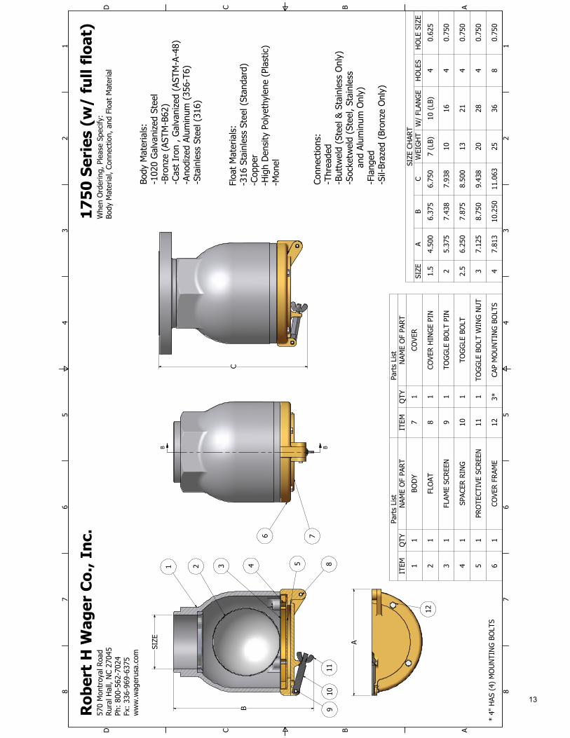
SIZE
CH
ART
SIZE
AB
CW
EIG
HT
W/
FLAN
GE
HO
LES
HO
LE S
IZE
1.5
4.50
06.
375
6.75
07
(LB)
10 (
LB)
40.
625
25.
375
7.43
87.
938
1016
40.
750
2.5
6.25
07.
875
8.50
013
214
0.75
0
37.
125
8.75
09.
438
2028
40.
750
47.
813
10.2
5011
.063
2536
80.
750
Part
s Li
stIT
EMQ
TYN
AME
OF
PART
11
BOD
Y
21
FLO
AT
31
FLAM
E SC
REEN
41
SPAC
ER R
ING
51
PRO
TECT
IVE
SCRE
EN
61
COVE
R F
RAM
E
Part
s Li
stIT
EMQ
TYN
AME
OF
PART
71
COVE
R
81
COVE
R H
ING
E PI
N
91
TOG
GLE
BO
LT P
IN
101
TOG
GLE
BO
LT
111
TOG
GLE
BO
LT W
ING
NU
T
123*
CAP
MO
UN
TIN
G B
OLT
S
B B
Rob
ert
H W
ager
Co.
, In
c.57
0 M
ontr
oyal
Roa
dRur
al H
all,
NC
2704
5Ph
: 80
0-56
2-70
24Fx
: 33
6-96
9-63
75w
ww
.wag
erus
a.co
m
17
50
Ser
ies
(w/
full
floa
t)W
hen
Ord
erin
g, P
leas
e Sp
ecify
:Bo
dy M
ater
ial,
Conn
ectio
n, a
nd F
loat
Mat
eria
l
Body
Mat
eria
ls:
-102
0 G
alva
nize
d St
eel
-Bro
nze
(AST
M-B
62)
-Cas
t Ir
on ,
Gal
vani
zed
(AST
M-A
-48)
-Ano
dize
d Al
umin
um (
356-
T6)
-Sta
inle
ss S
teel
(31
6)
Floa
t M
ater
ials
:-3
16 S
tain
less
Ste
el (
Stan
dard
)-C
oppe
r-H
igh
Den
sity
Pol
yeth
ylen
e (P
last
ic)
-Mon
el
Conn
ectio
ns:
-Thr
eade
d -B
uttw
eld
(Ste
el &
Sta
inle
ss O
nly)
-S
ocke
twel
d (S
teel
, St
ainl
ess
an
d Al
umin
um O
nly)
-Fla
nged
-Sil-
Braz
ed (
Bron
ze O
nly)
1 2 3 4 5
6 7
12
89
1011
SIZE
B
A
C
* 4"
HAS
(4)
MO
UN
TIN
G B
OLT
S
13
1 1
2 2
3 3
4 4
5 5
6 6
7 7
8 8
AA
BB
CC
DD
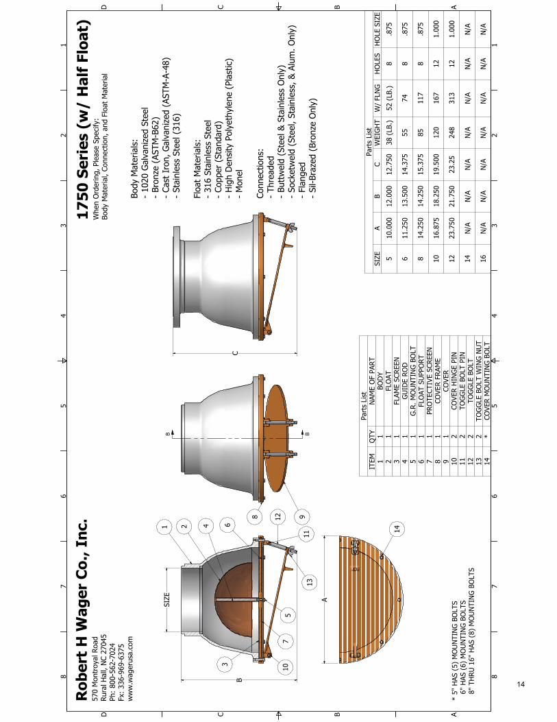
Part
s Li
stIT
EMQ
TYN
AME
OF
PAR
T1
1BO
DY
21
FLO
AT3
1FL
AME
SCRE
EN4
1G
UID
E RO
D5
1G
.R. M
OU
NTI
NG
BO
LT6
1FL
OAT
SU
PPO
RT7
1PR
OTE
CTIV
E SC
REEN
81
COVE
R FR
AME
91
COVE
R10
2CO
VER
HIN
GE
PIN
112
TOG
GLE
BO
LT P
IN12
2TO
GG
LE B
OLT
132
TOG
GLE
BO
LT W
ING
NU
T14
*CO
VER
MO
UN
TIN
G B
OLT
Part
s Li
stSI
ZEA
BC
WEI
GH
TW
/ FL
NG
HO
LES
HO
LE S
IZE
510
.000
12.0
0012
.750
38 (
LB.)
52 (
LB.)
8.8
75
611
.250
13.5
0014
.375
5574
8.8
75
814
.250
14.2
5015
.375
8511
78
.875
1016
.875
18.2
5019
.500
120
167
121.
000
1223
.750
21.7
5023
.25
248
313
121.
000
14N
/AN
/AN
/AN
/AN
/AN
/AN
/A
16N
/AN
/AN
/AN
/AN
/AN
/AN
/A
B B
Rob
ert
H W
ager
Co.
, In
c.57
0 M
ontr
oyal
Roa
dRur
al H
all,
NC
2704
5Ph
: 80
0-56
2-70
24Fx
: 33
6-96
9-63
75w
ww
.wag
erus
a.co
m
17
50
Ser
ies
(w/
Hal
f Fl
oat)
Whe
n O
rder
ing,
Ple
ase
Spec
ify:
Body
Mat
eria
l, Co
nnec
tion,
and
Flo
at M
ater
ial
Body
Mat
eria
ls:
- 10
20 G
alva
nize
d St
eel
- Br
onze
(AS
TM-B
62)
- Ca
st I
ron,
Gal
vani
zed
(AST
M-A
-48)
- St
ainl
ess
Stee
l (31
6)
Floa
t M
ater
ials
:-
316
Stai
nles
s St
eel
- Co
pper
(St
anda
rd)
- H
igh
Den
sity
Pol
yeth
ylen
e (P
last
ic)
- M
onel
Conn
ectio
ns:
- Th
read
ed-
Butt
wel
d (S
teel
& S
tain
less
Onl
y)-
Sock
etw
eld
(Ste
el, S
tain
less
, & A
lum
. Onl
y)-
Flan
ged
- Si
l-Bra
zed
(Bro
nze
Onl
y)
* 5"
HAS
(5)
MO
UN
TIN
G B
OLT
S
6"
HAS
(6)
MO
UN
TIN
G B
OLT
S
8"
THR
U 1
6" H
AS (
8) M
OU
NTI
NG
BO
LTS
B
A
SIZE
C
1 2 4
5
912
14
8
11
10
3
7
13
6
14
Series
Sizes
Connections
Materials
Series
Sizes
Connections
Materials
Series
Sizes
Connections
Materials
Series
Sizes
Connections
Materials
Series
Sizes
Connections
Materials
Series
Sizes
Connections
Materials
Series
Sizes
Connections
Materials
Series
Sizes
Connections
Materials
Series
Sizes
Connections
Materials
Series
Sizes
Connections
Materials
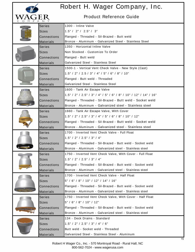
Robert H. Wager Company, Inc.Product Reference Guide
Galvanized Steel - Stainless Steel
Galvanized Steel - Stainless Steel - Aluminum
Butt weld - Socket weld - Threaded
1300 - Inline Valve
Bronze - Aluminum - Galvanized Steel - Stainless Steel
Flanged - Threaded - Sil-Brazed - Butt weld
Flanged - Butt weld
Galvanized Steel - Stainless Steel
1750 - Inverted Vent Check Valve, With Cover - Half Float
Bronze - Aluminum - Galvanized steel - Stainless steel
Flanged - Threaded - Sil-Brazed - Butt weld - Socket weld
1700 - Inverted Vent Check Valve - Full Float
Flanged - Threaded - Sil-Brazed - Butt weld - Socket weld
1660 - Tank Air Escape Valve, With Cover
1.5" / 2" / 2.5" / 3" / 4" / 5" / 6" / 8" / 10" / 12" / 14" / 16"
Non Stocked - Customize To Order
1.5" / 2" / 2.5" / 3"
Bronze - Aluminum - Galvanized steel - Stainless steel
1350 - Horizontal Inline Valve
Bronze - Aluminum - Galvanized steel - Stainless steel
Flanged - Threaded - Sil-Brazed - Butt weld - Socket weld
1.5" / 2" / 2.5" / 3" / 4"
1500-1 - Vertical Vent Check Valve - New Style (Cast)
1.5" / 2" / 2.5 / 3" / 4" / 5" / 6" / 8" / 10"
Flanged - Butt weld - Threaded
Flanged - Threaded - Sil-Brazed - Butt weld - Socket weld
Flanged - Threaded - Sil-Brazed - Butt weld - Socket weld
1.5" / 2" / 2.5" / 3" / 4" / 6"
134 - Deck Drains - Standard
Bronze - Aluminum - Galvanized steel - Stainless steel
Bronze - Aluminum - Galvanized steel - Stainless steel
1750 - Inverted Vent Check Valve, With Cover - Full Float
1700 - Inverted Vent Check Valve - Half Float
5" / 6" / 8" / 10" / 12" / 14" / 16"
Flanged - Threaded - Sil-Brazed - Butt weld - Socket weld
1.5" / 2" / 2.5" / 3" / 4"
5" / 6" / 8" / 10" / 12"
1.5" / 2" / 2.5" / 3" / 4" / 5" / 6" / 8" / 10" / 12"
1600 - Tank Air Escape Valve
Bronze - Aluminum - Galvanized steel - Stainless steel
Robert H Wager Co., Inc. - 570 Montroyal Road - Rural Hall, NC800-562-7024 - www.wagerusa.com
15
Series
Sizes
Connections
Materials
Series
Sizes
Connections
Materials
Series
Sizes
Connections
Materials
Series
Sizes
Connections
Materials
Name
Sizes
Connections
Materials
Name
Sizes
Connections
Materials
Name
P/N
Connections
Materials
Name
P/N
Connections
Materials
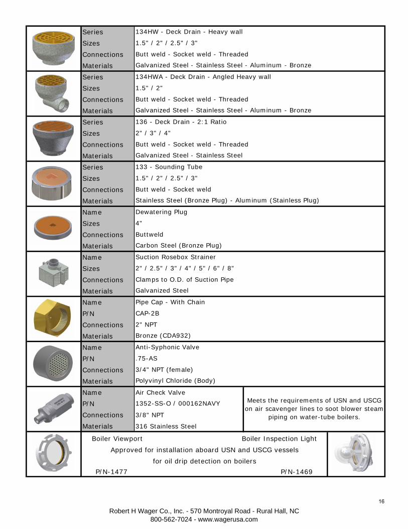
Name Air Check Valve
P/N
Connections 3/8" NPT
Materials 316 Stainless Steel
3/4" NPT (female)
Polyvinyl Chloride (Body)
Meets the requirements of USN and USCG on air scavenger lines to soot blower steam
piping on water-tube boilers.
1352-SS-O / 000162NAVY
Anti-Syphonic Valve
.75-AS
Dewatering Plug
4"
Buttweld
Suction Rosebox Strainer
2" / 2.5" / 3" / 4" / 5" / 6" / 8"
Clamps to O.D. of Suction Pipe
Galvanized Steel
Bronze (CDA932)
2" NPT
Galvanized Steel - Stainless Steel - Aluminum - Bronze
Butt weld - Socket weld - Threaded
1.5" / 2" / 2.5" / 3"
134HW - Deck Drain - Heavy wall
1.5" / 2"
Galvanized Steel - Stainless Steel
2" / 3" / 4"
136 - Deck Drain - 2:1 Ratio
Galvanized Steel - Stainless Steel - Aluminum - Bronze
Butt weld - Socket weld - Threaded
134HWA - Deck Drain - Angled Heavy wall
CAP-2B
Pipe Cap - With Chain
Stainless Steel (Bronze Plug) - Aluminum (Stainless Plug)
Butt weld - Socket weld
Carbon Steel (Bronze Plug)
1.5" / 2" / 2.5" / 3"
133 - Sounding Tube
Butt weld - Socket weld - Threaded
Boiler Viewport Boiler Inspection Light
Approved for installation aboard USN and USCG vessels
for oil drip detection on boilers
P/N-1477 P/N-1469
Robert H Wager Co., Inc. - 570 Montroyal Road - Rural Hall, NC800-562-7024 - www.wagerusa.com
16