Embed Size (px)
Citation preview
ILASS Americas, 19th Annual Conference on Liquid Atomization and Spray Systems, Toronto, Canada, May 2006
Modeling Charge Preparation in Diesel HCCI Engines Using Low Pressure Injection
Yong Sun* and Rolf D. Reitz Engine Research Center, Department of Mechanical Engineering
University of Wisconsin-Madison Madison, WI 53706-1609 USA
Abstract
Homogeneous Charge Compression Ignition (HCCI) combustion is being considered as an alternative to conven-tional engine combustion systems due to its high efficiency and low engine-out emissions. A homogeneous charge is designed to burn spontaneously and simultaneously through an auto-ignition process in this combustion concept. One way to prepare a homogeneous mixture is to inject fuel early into the cylinder using a low-pressure hollow-cone spray injector. A multi-dimensional Computational Fluid Dynamics (CFD) code, the KIVA-3V Release2 code with updated models, was employed in this study. Using KIVA, unrealistic spray structures were predicted at high ambi-ent pressures in Cartesian meshes. This problem was solved using a combination of two techniques: use of an inde-pendent cylindrical collision mesh with random rotation and coupling the gas and liquid phases using polar interpo-lation. In addition, a trajectory exclusion criterion was used to avoid unphysical collisions between droplets. The updated models were validated by comparing simulation results with experiments at different ambient and injection pressures. An inhomogeneity assessment concept was proposed to evaluate the mixture quality for HCCI combus-tion and the effects of Start-of-Injection (SOI) timing on charge preparation were investigated. The results show that, the unrealistic spray structures are mainly due to the grid dependency of the O’Rourke collision model and gas and liquid phase coupling. Using the updated models, significant improvements were achieved and axisymmetric and reasonable spray structures were predicted. Both the spray structure and penetration of the simulation results match the experiments very well. The inhomogeneity concept is effective in evaluating mixture quality for HCCI combus-tion. There is an optimum SOI timing around Bottom Dead Center (BDC) which minimizes spray-wall impingement and mixture inhomogeneity.
*Corresponding author
Introduction Future diesel engine technologies will need to in-
corporate advanced combustion strategies for achieving low emissions while maintaining fuel economy and power density. It will be necessary to operate seam-lessly over broad load and speed ranges when condi-tions change between different combustion regimes.
HCCI combustion is being considered as an alter-native to conventional engine combustion systems. It has the potential to eliminate noxious engine-out emis-sions while producing diesel-like engine efficiencies. A homogeneous charge is designed to burn spontaneously and entirely through an auto-ignition process in this combustion concept.
However, when direct injection of fuel into the cyl-inder during intake or early compression stroke is used for mixture preparation, the use of conventional high pressure injection systems is limited by the relatively low in-cylinder gas density due to spray impingement on the cylinder walls [1]. Too much wall impingement can not only deteriorate the quality of the charge mix-ture, increase fuel consumption and unburned hydro-carbon emissions, but also lead to lubrication oil con-tamination. Therefore, it is of interest to consider low-pressure hollow-cone injection systems as an alternative. However, even using low-pressure hollow-cone injec-tion systems, wall wetting is still found in engine ex-periments [2].
In this study, KIVA-3V Release2 code [3] with improved numerical models was used to explore the charge preparation in a diesel HCCI engine using a low-pressure hollow-cone spray injector. Several nu-merical models in KIVA were updated and the im-proved models were validated by comparing simulation results to experiments. An inhomogeneity concept was proposed to evaluate the effects of SOI timing on diesel HCCI charge preparation.
Numerical Approach
The CFD code used in the simulations was a ver-sion of the KIVA-3V Release2 code with improve-ments in various physical and chemistry models devel-oped at the Engine Research Center, University of Wis-consin-Madison.
The RNG k-İ model [4] was used for in-cylinder turbulence simulation. The Linearized Instability Sheet Atomization (LISA) breakup model [5] was used to calculate the primary breakup process of the fuel drop-lets and the Taylor Analogy Breakup (TAB) model [6] was used for the secondary breakup calculation.
An advanced unsteady vaporization model [7] was applied to predict the droplet evaporation process. A droplet collision model based on the stochastic particle method [8] was used to calculate the droplet collision and coalescence. The effects associated with spray/wall interactions including droplet splash, film spreading
due to impingement forces and motion due to film iner-tia were considered in the wall-film model [9].
Engine Specifications
The engine considered was a Caterpillar 3401E sin-gle cylinder oil test engine. The specifications and operating conditions of the engine are listed in Table 1.
Engine type Caterpillar 3401E Bore× Stroke (mm) 137.2 × 165.1 Engine valve timing (°CA) EVC=-355, IVC=-143,
EVO= 130, IVO= 335
Swirl Ratio 1.0 Injection pressure (MPa) 10 Injector spray cone angle (°) 90 Speed (rpm) 1737 Amount of fuel injected (g) 0.0946 Boost pressure (MPa) 0.3 EGR (%) 0
Table 1. Engine specifications and operation condi-tions
To account for the influence of intake flow on
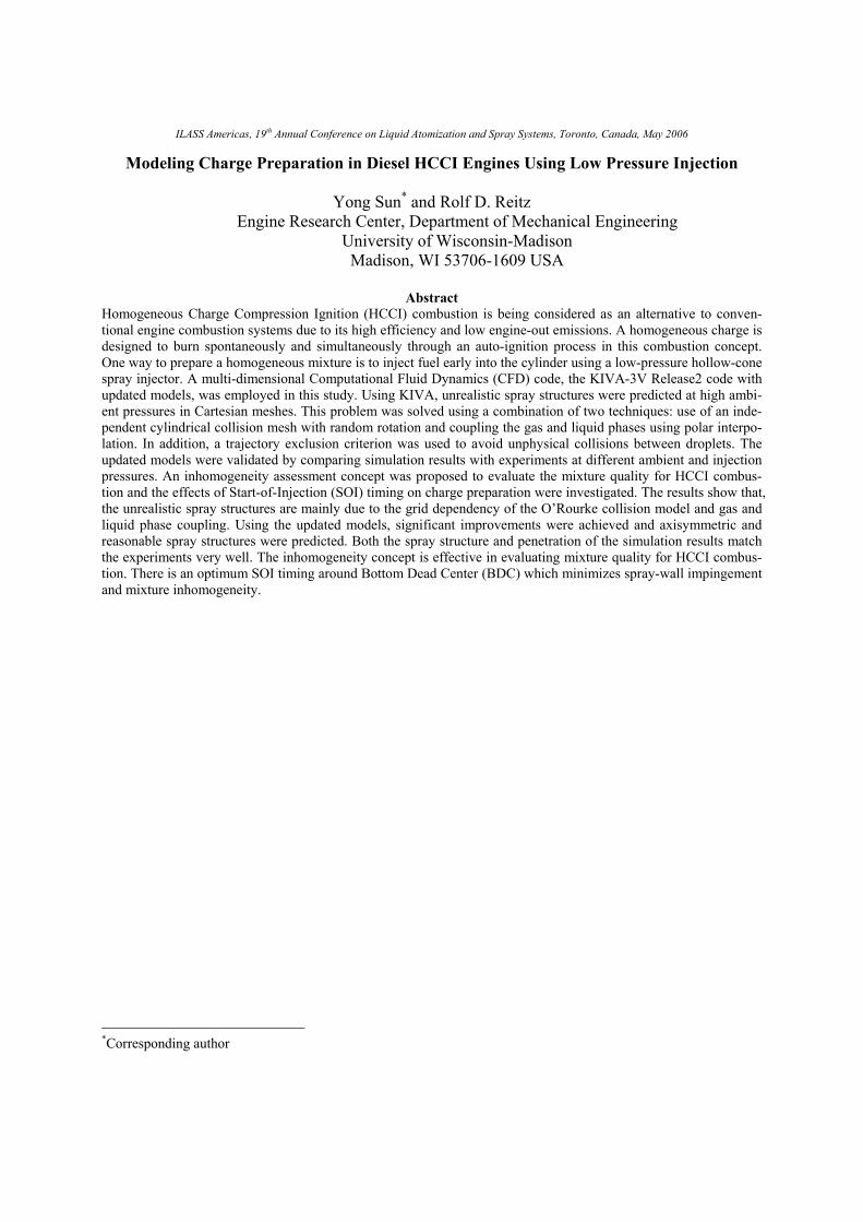
spray, a full 3-D mesh with intake and exhaust ports and valve motion was used to model the engine. The computational mesh is shown in Figure 1.
Figure 1. Computational mesh at Top Dead Center (TDC)
Hollow-Cone Spray at High Ambient Pressure
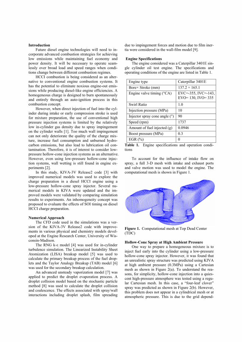
One way to prepare a homogeneous mixture is to inject fuel early into the cylinder using a low-pressure hollow-cone spray injector. However, it was found that an unrealistic spray structure was predicted using KIVA at high ambient pressure (0.3MPa) using a Cartesian mesh as shown in Figure 2(a). To understand the rea-sons, for simplicity, hollow-cone injection into a quies-cent high-pressure atmosphere was tested using a regu-lar Cartesian mesh. In this case, a “four-leaf clover” spray was predicted as shown in Figure 2(b). However, this problem does not appear in a cylindrical mesh or at atmospheric pressure. This is due to the grid depend-
ency of O’Rourke collision model and the gas and liq-uid phase coupling method used in KIVA according to Nordin, Schmidt and other researchers [10, 11]. This problem was solved using a combination of two tech-niques proposed by these researchers: use of a cylindri-cal collision mesh and by coupling the gas and liquid phases using polar interpolation. These techniques were used in this study and the details are described as fol-lows. A trajectory exclusion criterion [11] was also included in the collision model to avoid unphysical droplet collisions.
(a) (b)
Figure 2. Unrealistic structures of hollow-cone sprays at high ambient pressure (0.3MPa) in Cartesian mesh computations using KIVA
Cylindrical collision mesh with random rotation
The “four-leaf clover” spray structure shown in Figure 2(b) was found to be mainly due to the mesh dependency of the O’Rourke collision model [8] used in KIVA. O’Rourke assumes that the probability of a droplet, i, colliding with any other droplet, j, is given by:
, ,,
i j i ji j
v tp
VV '
(1)
Only parcels located in the same computational cell
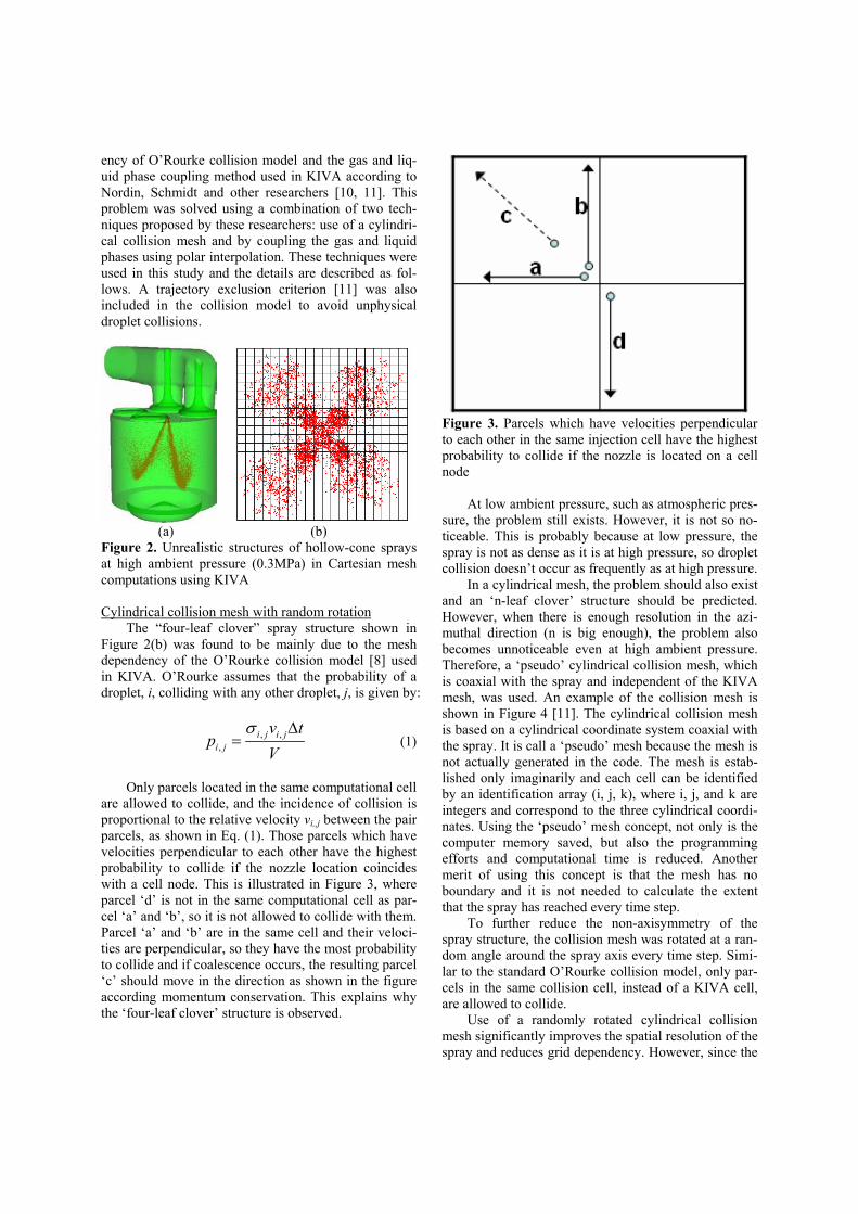
are allowed to collide, and the incidence of collision is proportional to the relative velocity vi,,j between the pair parcels, as shown in Eq. (1). Those parcels which have velocities perpendicular to each other have the highest probability to collide if the nozzle location coincides with a cell node. This is illustrated in Figure 3, where parcel ‘d’ is not in the same computational cell as par-cel ‘a’ and ‘b’, so it is not allowed to collide with them. Parcel ‘a’ and ‘b’ are in the same cell and their veloci-ties are perpendicular, so they have the most probability to collide and if coalescence occurs, the resulting parcel ‘c’ should move in the direction as shown in the figure according momentum conservation. This explains why the ‘four-leaf clover’ structure is observed.
Figure 3. Parcels which have velocities perpendicular to each other in the same injection cell have the highest probability to collide if the nozzle is located on a cell node
At low ambient pressure, such as atmospheric pres-
sure, the problem still exists. However, it is not so no-ticeable. This is probably because at low pressure, the spray is not as dense as it is at high pressure, so droplet collision doesn’t occur as frequently as at high pressure.
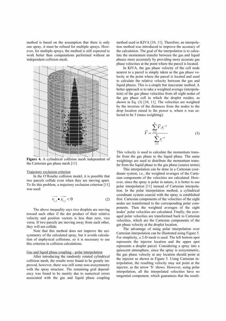
In a cylindrical mesh, the problem should also exist and an ‘n-leaf clover’ structure should be predicted. However, when there is enough resolution in the azi-muthal direction (n is big enough), the problem also becomes unnoticeable even at high ambient pressure. Therefore, a ‘pseudo’ cylindrical collision mesh, which is coaxial with the spray and independent of the KIVA mesh, was used. An example of the collision mesh is shown in Figure 4 [11]. The cylindrical collision mesh is based on a cylindrical coordinate system coaxial with the spray. It is call a ‘pseudo’ mesh because the mesh is not actually generated in the code. The mesh is estab-lished only imaginarily and each cell can be identified by an identification array (i, j, k), where i, j, and k are integers and correspond to the three cylindrical coordi-nates. Using the ‘pseudo’ mesh concept, not only is the computer memory saved, but also the programming efforts and computational time is reduced. Another merit of using this concept is that the mesh has no boundary and it is not needed to calculate the extent that the spray has reached every time step.
To further reduce the non-axisymmetry of the spray structure, the collision mesh was rotated at a ran-dom angle around the spray axis every time step. Simi-lar to the standard O’Rourke collision model, only par-cels in the same collision cell, instead of a KIVA cell, are allowed to collide.
Use of a randomly rotated cylindrical collision mesh significantly improves the spatial resolution of the spray and reduces grid dependency. However, since the
method is based on the assumption that there is only one spray, it must be refined for multiple sprays. How-ever, for multiple sprays, the method is still expected to work better than computations performed without an independent collision mesh.
Figure 4. A cylindrical collision mesh independent of the Cartesian gas phase mesh [11]
Trajectory exclusion criterion
In the O’Rourke collision model, it is possible that two parcels collide even when they are moving apart. To fix this problem, a trajectory exclusion criterion [11] was used:
, , 0i j i jv xx �JJG JJJG
(2) The above inequality says two droplets are moving
toward each other if the dot product of their relative velocity and position vectors is less than zero, vice versa. If two parcels are moving away from each other, they will not collide.
Note that this method does not improve the axi-symmetry of the calculated spray, but it avoids calcula-tion of unphysical collisions, so it is necessary to use this criterion in collision calculations.
Gas and liquid phase coupling—polar interpolation
After introducing the randomly rotated cylindrical collision mesh, the results were found to be greatly im-proved, however, there was still some non-axisymmetry with the spray structure. The remaining grid depend-ency was found to be mainly due to numerical errors associated with the gas and liquid phase coupling
method used in KIVA [10, 11]. Therefore, an interpola-tion method was introduced to improve the accuracy of the calculation. The goal of the interpolation is to calcu-late the momentum transfer between the gas and liquid phases more accurately by providing more accurate gas phase velocities at the point where the parcel is located.
In KIVA, the gas phase velocity of the cell node nearest to a parcel is simply taken as the gas phase ve-locity at the point where the parcel is located and used to calculate the relative velocity between the gas and liquid phases. This is a simple but inaccurate method. A better approach is to take a weighted average (interpola-tion) of the gas phase velocities from all eight nodes of the gas phase cell in which the droplet resides, as shown in Eq. (3) [10, 11]. The velocities are weighted by the inverses of the distances from the nodes to the drop location raised to the power n, where n was se-lected to be 3 (mass weighting):
8
18
1
ni i
i
ni
i
V rV
r
�
�
¦
¦
JGJG
(3)
This velocity is used to calculate the momentum trans-fer from the gas phase to the liquid phase. The same weightings are used to distribute the momentum trans-fer from the liquid phase to the gas phase (source terms).
This interpolation can be done in a Cartesian coor-dinate system, i.e., the weighted averages of the Carte-sian components of the velocities are calculated. How-ever, since the spray is polar in nature, it is better to use polar interpolation [11] instead of Cartesian interpola-tion. In the polar interpolation method, a cylindrical coordinate system coaxial with the spray is established first. Cartesian components of the velocities of the eight nodes are transformed to the corresponding polar com-ponents. Then the weighted averages of the eight nodes’ polar velocities are calculated. Finally, the aver-aged polar velocities are transformed back to Cartesian velocities, which are the Cartesian components of the gas phase velocity at the droplet location.
The advantage of using polar interpolation over Cartesian interpolation can be illustrated using Figure 5. For simplicity, a 2-D mesh is used. The left bottom spot represents the injector location and the upper spot represents a droplet parcel. Considering a spray into a quiescent atmosphere, since the spray is axisymmetric, the gas phase velocity at any location should point at the injector as shown in Figure 5. Using Cartesian in-terpolation, the resulting velocity may not point at the injector, as the arrow ‘b’ shows. However, using polar interpolation, all the interpolated velocities have no tangential component, which guarantees that the result-
ing velocity also has no tangential component, i.e., the resulting velocity also points at the injector, as the ar-row ‘a’ shows. Since polar interpolation represents the nature of the spray better than Cartesian interpolation, it is suggested and used in this study.
Figure 5. Advantage of using polar interpolation over Cartesian interpolation (a: polar interpolation result. b: Cartesian interpolation result)
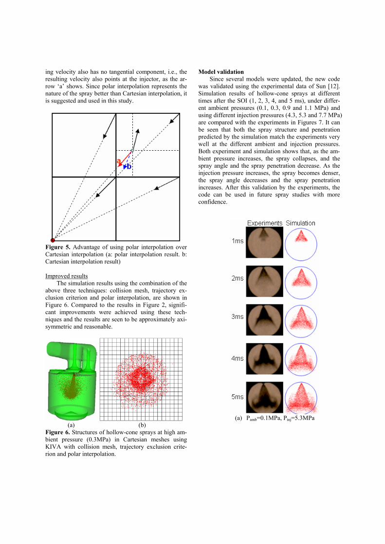
Improved results
The simulation results using the combination of the above three techniques: collision mesh, trajectory ex-clusion criterion and polar interpolation, are shown in Figure 6. Compared to the results in Figure 2, signifi-cant improvements were achieved using these tech-niques and the results are seen to be approximately axi-symmetric and reasonable.
(a) (b)
Figure 6. Structures of hollow-cone sprays at high am-bient pressure (0.3MPa) in Cartesian meshes using KIVA with collision mesh, trajectory exclusion crite-rion and polar interpolation.
Model validation Since several models were updated, the new code
was validated using the experimental data of Sun [12]. Simulation results of hollow-cone sprays at different times after the SOI (1, 2, 3, 4, and 5 ms), under differ-ent ambient pressures (0.1, 0.3, 0.9 and 1.1 MPa) and using different injection pressures (4.3, 5.3 and 7.7 MPa) are compared with the experiments in Figures 7. It can be seen that both the spray structure and penetration predicted by the simulation match the experiments very well at the different ambient and injection pressures. Both experiment and simulation shows that, as the am-bient pressure increases, the spray collapses, and the spray angle and the spray penetration decrease. As the injection pressure increases, the spray becomes denser, the spray angle decreases and the spray penetration increases. After this validation by the experiments, the code can be used in future spray studies with more confidence.
(a) Pamb=0.1MPa, Pinj=5.3MPa
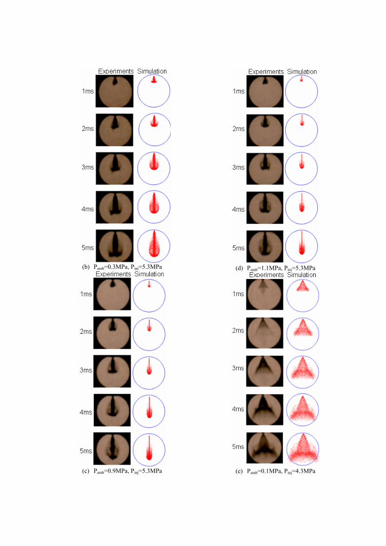
(b) Pamb=0.3MPa, Pinj=5.3MPa
(c) Pamb=0.9MPa, Pinj=5.3MPa
(d) Pamb=1.1MPa, Pinj=5.3MPa
(e) Pamb=0.1MPa, Pinj=4.3MPa
(f) Pamb=0.1MPa, Pinj=7.7MPa
Figure 7. Comparison of the hollow-cone spray be-tween experiments and simulation
Inhomogeneity
An inhomogeneity concept was proposed to evalu-ate the quality of fuel/air mixtures in engine simulations. The fuel chemistry is deactivated, i.e., only fuel spray and mixing is solved. The calculation ends at -10°CA ATDC, which is close to when ignition normally occurs in HCCI engine combustion. At -10°CA ATDC, first, the equivalence ratio in each computational cell is cal-culated using the concentration of C, H and O atoms (those in the main combustion products and EGR (CO2 and H2O) are excluded); as
2[ ] 0.5[ ]
[ ]C H
O�
) (4)
Then the statistical mean equivalence ratio in the
whole computational domain is calculated using the gas phase mass in each cell as a weighting factor
#
#
cells
i iicells
ii
m
m
G
G
))
¦
¦ (5)
The standard deviation of the equivalence ratio in
the computational domain is defined as
#2
#
( )cells
i ii
cells
ii
mSD
m
G
G
) �)
¦
¦ (6)
Finally, the normalized standard deviation of the
equivalence ratio, which is called inhomogeneity, is calculated by
SDNSD ) (7)
The inhomogeneity value (NSD) is an indicator of
the mixture quality. The higher the inhomogeneity, the less homogeneous the mixture is. Since fuel chemistry is not considered, computer time is greatly reduced and the approach can be used for mixture preparation opti-mization, especially for HCCI combustion, since, to achieve HCCI combustion, charge inhomogeneities should be minimized.
SOI Swing Study Results and Discussion
The effects of SOI timing of single injections on diesel HCCI charge preparation were investigated. The SOI timing was varied from -330ºCA ATDC to -120ºCA ATDC.
-360 -310 -260 -210 -160 -1100.00
0.05
0.10
0.15
0.20
0.25
0.30
0.0
0.6
1.2
1.8
2.4
3.0
3.6
Wal
l-film
fuel
frac
tion
[-]
SOI [Deg. ATDC]
Inho
mog
enei
ty (N
SD
)
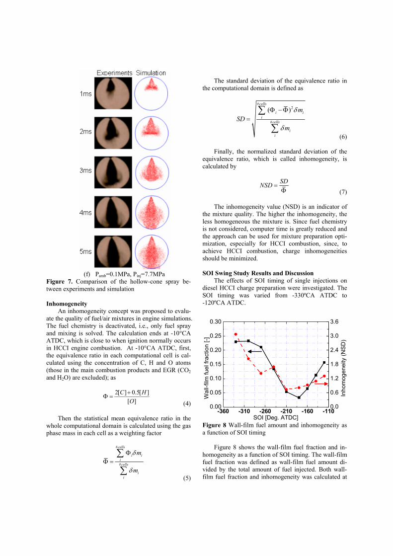
Figure 8 Wall-film fuel amount and inhomogeneity as a function of SOI timing
Figure 8 shows the wall-film fuel fraction and in-
homogeneity as a function of SOI timing. The wall-film fuel fraction was defined as wall-film fuel amount di-vided by the total amount of fuel injected. Both wall-film fuel fraction and inhomogeneity was calculated at
-10ºCA ATDC. From Figure 8, both variables are seen to decrease as the SOI timing is retarded from intake TDC, reach a minimum value at SOI timing around BDC, and increase again with further delay of the SOI timing. There is thus an optimum SOI timing around BDC for the minimization of spray-wall wetting and charge inhomogeneity.
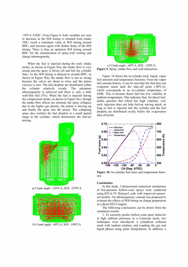
When the fuel is injected during the early intake stroke, as shown in Figure 9(a), the intake flow is very strong and the spray is blown off and hits the cylinder liner. As the SOI timing is delayed to around BDC, as shown in Figure 9(b), the intake flow is not so strong because the valves are about to close and the piston velocity is zero. The fuel droplets are distributed within the cylinder relatively evenly. The minimum inhomogeneity is achieved and there is only a little wall-film fuel (3%). When the fuel is injected during the compression stroke, as shown in Figure 9(c), though the intake flow effects are minimal, the spray collapses due to the higher gas density, the piston is moving up and finally the spray hits the piston. The collapsing spray also confines the fuel droplets in a small spatial range in the cylinder, which deteriorates the fuel-air mixing.
a) Crank angle: -230ºCA, SOI: -270ºCA
b) Crank angle: -60ºCA, SOI: -180ºCA
c) Crank angle: -60ºCA, SOI: -120ºCA
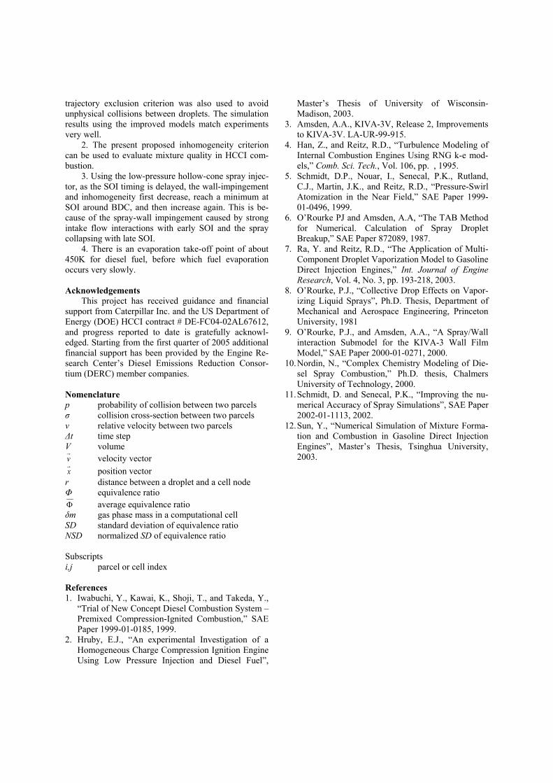
Figure 9. Spray, intake flow and wall interaction Figure 10 shows the in-cylinder total, liquid, vapor
fuel amounts and temperature histories. From the vapor fuel amount history, it can be seen that the fuel does not evaporate much until the take-off point (-80ºCA), which corresponds to an in-cylinder temperature of 450K. This is because diesel fuel has low volatility at ambient temperature. This indicates that, for diesel fuel, unlike gasoline fuel which has high volatility, very early injection does not help fuel-air mixing much, as long as fuel is injected into the cylinder and the fuel droplets are distributed evenly before the evaporation take-off point.
-180 -150 -120 -90 -60 -30 00.00
0.02
0.04
0.06
0.08
0.10
350
450
550
650
750
850 Total fuel Liquid fuel Vapor fuel
Fuel
mas
s (g
)
CA (Deg. ATDC) T
empe
ratu
re (K
) Temperature
Figure 10. In-cylinder fuel mass and temperature histo-ries
Conclusions
In this study, 3-dimensional numerical simulations of low-pressure hollow-cone sprays were conducted using KIVA-3V Release2 code with improved numeri-cal models. An inhomogeneity concept was proposed to evaluate the effects of SOI timing on charge preparation in a diesel HCCI engine.
The following conclusions can be drawn from the simulation results:
1. To correctly predict hollow-cone spray behavior at high ambient pressures in a Cartesian mesh, two techniques were introduced: a cylindrical collision mesh with random rotation, and coupling the gas and liquid phases using polar interpolation. In addition, a
trajectory exclusion criterion was also used to avoid unphysical collisions between droplets. The simulation results using the improved models match experiments very well.
2. The present proposed inhomogeneity criterion can be used to evaluate mixture quality in HCCI com-bustion.
3. Using the low-pressure hollow-cone spray injec-tor, as the SOI timing is delayed, the wall-impingement and inhomogeneity first decrease, reach a minimum at SOI around BDC, and then increase again. This is be-cause of the spray-wall impingement caused by strong intake flow interactions with early SOI and the spray collapsing with late SOI.
4. There is an evaporation take-off point of about 450K for diesel fuel, before which fuel evaporation occurs very slowly.
Acknowledgements
This project has received guidance and financial support from Caterpillar Inc. and the US Department of Energy (DOE) HCCI contract # DE-FC04-02AL67612, and progress reported to date is gratefully acknowl-edged. Starting from the first quarter of 2005 additional financial support has been provided by the Engine Re-search Center’s Diesel Emissions Reduction Consor-tium (DERC) member companies.
Nomenclature p probability of collision between two parcels ı collision cross-section between two parcels v relative velocity between two parcels ǻt time step V volume vG
velocity vector xG
position vector r distance between a droplet and a cell node ĭ equivalence ratio ) average equivalence ratio įm gas phase mass in a computational cell SD standard deviation of equivalence ratio NSD normalized SD of equivalence ratio Subscripts i,j parcel or cell index
References 1. Iwabuchi, Y., Kawai, K., Shoji, T., and Takeda, Y.,
“Trial of New Concept Diesel Combustion System – Premixed Compression-Ignited Combustion,” SAE Paper 1999-01-0185, 1999.
2. Hruby, E.J., “An experimental Investigation of a Homogeneous Charge Compression Ignition Engine Using Low Pressure Injection and Diesel Fuel”,
Master’s Thesis of University of Wisconsin-Madison, 2003.
3. Amsden, A.A., KIVA-3V, Release 2, Improvements to KIVA-3V. LA-UR-99-915.
4. Han, Z., and Reitz, R.D., “Turbulence Modeling of Internal Combustion Engines Using RNG k-e mod-els,” Comb. Sci. Tech., Vol. 106, pp. , 1995.
5. Schmidt, D.P., Nouar, I., Senecal, P.K., Rutland, C.J., Martin, J.K., and Reitz, R.D., “Pressure-Swirl Atomization in the Near Field,” SAE Paper 1999-01-0496, 1999.
6. O’Rourke PJ and Amsden, A.A, “The TAB Method for Numerical. Calculation of Spray Droplet Breakup,” SAE Paper 872089, 1987.
7. Ra, Y. and Reitz, R.D., “The Application of Multi-Component Droplet Vaporization Model to Gasoline Direct Injection Engines,” Int. Journal of Engine Research, Vol. 4, No. 3, pp. 193-218, 2003.
8. O’Rourke, P.J., “Collective Drop Effects on Vapor-izing Liquid Sprays”, Ph.D. Thesis, Department of Mechanical and Aerospace Engineering, Princeton University, 1981
9. O’Rourke, P.J., and Amsden, A.A., “A Spray/Wall interaction Submodel for the KIVA-3 Wall Film Model,” SAE Paper 2000-01-0271, 2000.
10. Nordin, N., “Complex Chemistry Modeling of Die-sel Spray Combustion,” Ph.D. thesis, Chalmers University of Technology, 2000.
11. Schmidt, D. and Senecal, P.K., “Improving the nu-merical Accuracy of Spray Simulations”, SAE Paper 2002-01-1113, 2002.
12. Sun, Y., “Numerical Simulation of Mixture Forma-tion and Combustion in Gasoline Direct Injection Engines”, Master’s Thesis, Tsinghua University, 2003.