Embed Size (px)
Citation preview
Presented by:Shawn Midlam-MohlerOhio State University
DEER 2004
Diesel HCCI with External Mixture Preparation
Overview
• DEER 2002 – “We think we can do external mixture formation HCCI, but we have no proof.”
• DEER 2003 – “We did external mixture formation, but our smoke numbers are a bit high.”
• DEER 2004 – “We’ve got excellent smoke and NOX, we’ve got a combustion model, and are starting multi-cylinder testing. But what good is external mixture formation?”
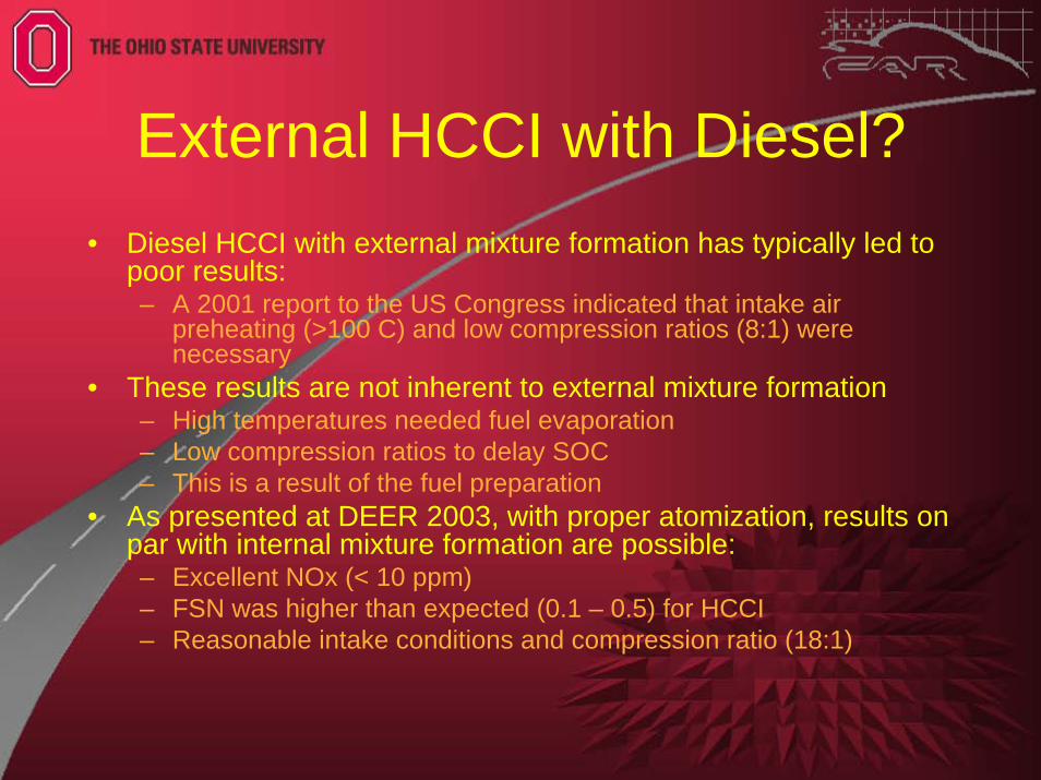
External HCCI with Diesel?• Diesel HCCI with external mixture formation has typically led to
poor results:– A 2001 report to the US Congress indicated that intake air
preheating (>100 C) and low compression ratios (8:1) were necessary
• These results are not inherent to external mixture formation– High temperatures needed fuel evaporation– Low compression ratios to delay SOC– This is a result of the fuel preparation
• As presented at DEER 2003, with proper atomization, results on par with internal mixture formation are possible:– Excellent NOx (< 10 ppm)– FSN was higher than expected (0.1 – 0.5) for HCCI– Reasonable intake conditions and compression ratio (18:1)
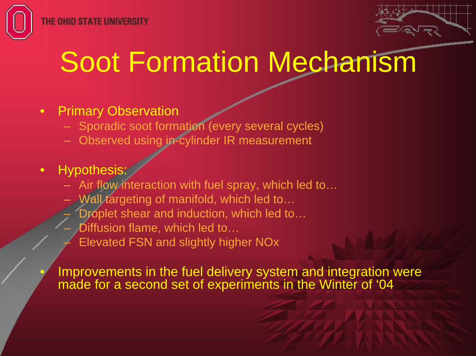
Soot Formation Mechanism• Primary Observation
– Sporadic soot formation (every several cycles)– Observed using in-cylinder IR measurement
• Hypothesis:– Air flow interaction with fuel spray, which led to…– Wall targeting of manifold, which led to…– Droplet shear and induction, which led to…– Diffusion flame, which led to…– Elevated FSN and slightly higher NOx
• Improvements in the fuel delivery system and integration were made for a second set of experiments in the Winter of ‘04
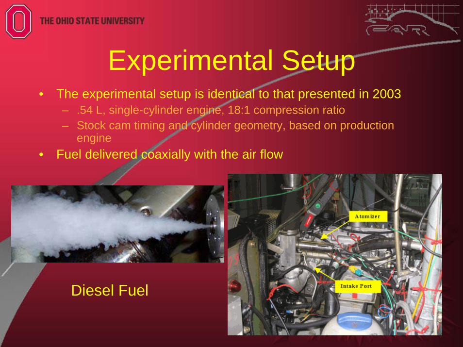
Experimental Setup• The experimental setup is identical to that presented in 2003
– .54 L, single-cylinder engine, 18:1 compression ratio– Stock cam timing and cylinder geometry, based on production
engine• Fuel delivered coaxially with the air flow
Diesel Fuel
Steps in External Mixture HCCI
• Continuous fuel injection into intake runner• Highly turbulent intake process = homogenous air-
droplet mixture at IVC• Micron-sized fuel droplets evaporate rapidly as
charge temperature rises• In-cylinder turbulence and diffusion completes the
mixing of fuel vapor with air• Before cool-flame chemical reactions are initiated
(around 600ºC), a homogeneous charge is established
• Combustion proceeds per the chemical processes that govern all HCCI combustion
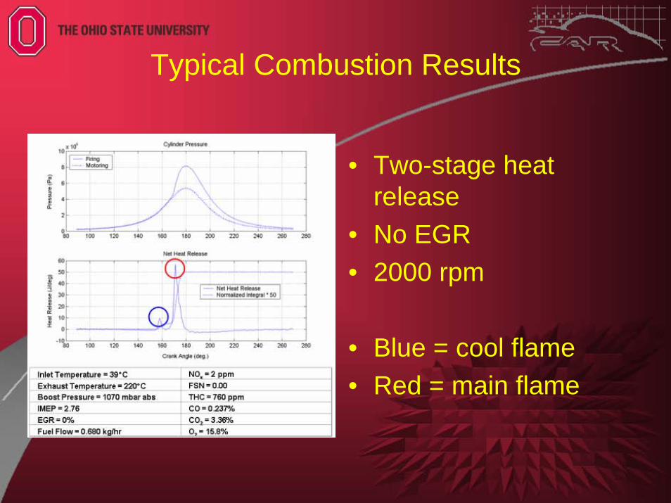
Typical Combustion Results
• Two-stage heat release
• No EGR• 2000 rpm
• Blue = cool flame• Red = main flame
Single-Cylinder Test Plan• Single Parameter Variations:
– Fueling Rate– EGR Rate– Boost Pressure– Intake Temperature– Engine Speed
• Mixed-Mode Operation– Effect of DI injection timing w/ background of HCCI
• The following slides summarize the results
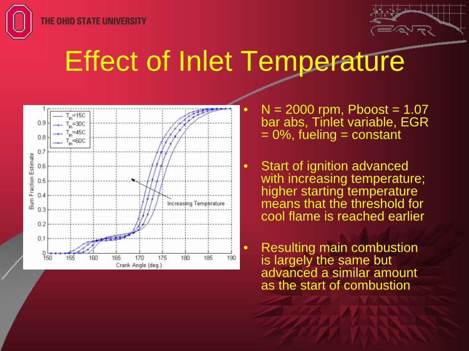
Effect of Inlet Temperature• N = 2000 rpm, Pboost = 1.07
bar abs, Tinlet variable, EGR = 0%, fueling = constant
• Start of ignition advanced with increasing temperature; higher starting temperature means that the threshold for cool flame is reached earlier
• Resulting main combustion is largely the same but advanced a similar amount as the start of combustion
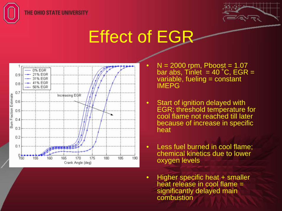
Effect of EGR• N = 2000 rpm, Pboost = 1.07
bar abs, Tinlet = 40 ˚C, EGR = variable, fueling = constant IMEPG
• Start of ignition delayed with EGR; threshold temperature for cool flame not reached till later because of increase in specific heat
• Less fuel burned in cool flame; chemical kinetics due to lower oxygen levels
• Higher specific heat + smaller heat release in cool flame = significantly delayed main combustion
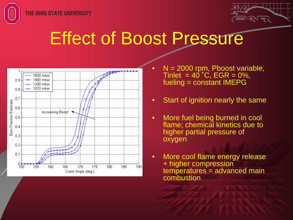
Effect of Boost Pressure• N = 2000 rpm, Pboost variable,
Tinlet = 40 ˚C, EGR = 0%, fueling = constant IMEPG
• Start of ignition nearly the same
• More fuel being burned in cool flame; chemical kinetics due to higher partial pressure of oxygen
• More cool flame energy release + higher compression temperatures = advanced main combustion
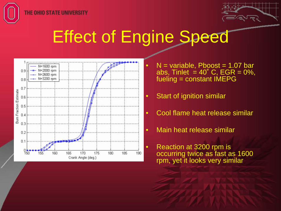
Effect of Engine Speed• N = variable, Pboost = 1.07 bar
abs, Tinlet = 40˚ C, EGR = 0%, fueling = constant IMEPG
• Start of ignition similar
• Cool flame heat release similar
• Main heat release similar
• Reaction at 3200 rpm is occurring twice as fast as 1600 rpm, yet it looks very similar
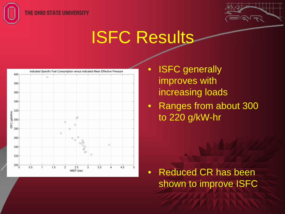
ISFC Results• ISFC generally
improves with increasing loads
• Ranges from about 300 to 220 g/kW-hr
• Reduced CR has been shown to improve ISFC
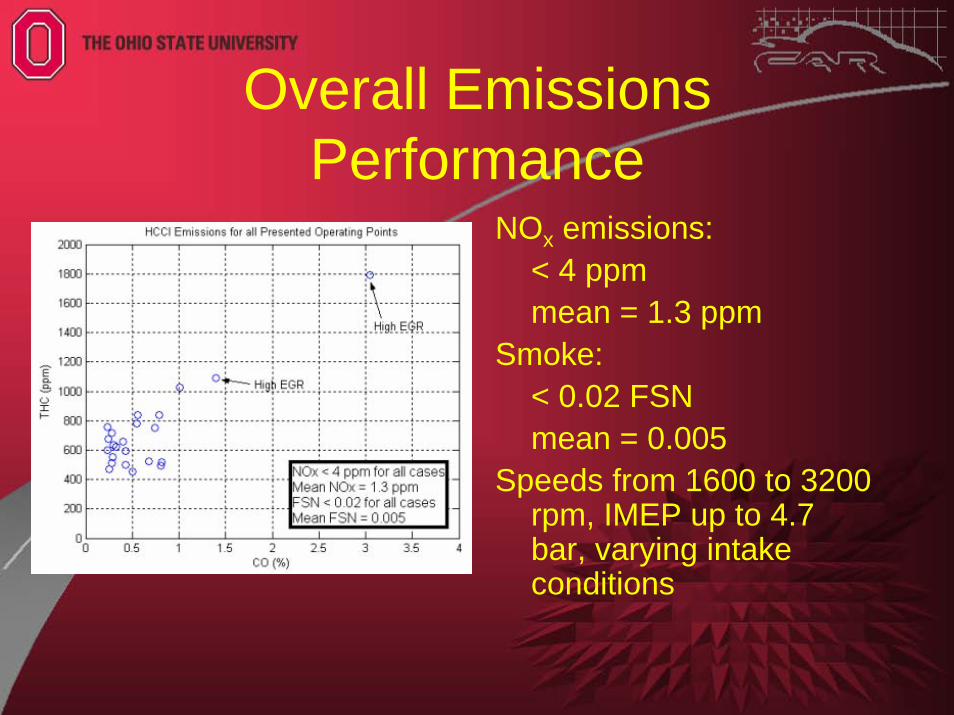
Overall Emissions Performance
NOx emissions:< 4 ppmmean = 1.3 ppm
Smoke:< 0.02 FSNmean = 0.005
Speeds from 1600 to 3200 rpm, IMEP up to 4.7 bar, varying intake conditions
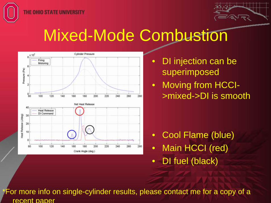
Mixed-Mode Combustion• DI injection can be
superimposed• Moving from HCCI-
>mixed->DI is smooth
• Cool Flame (blue)• Main HCCI (red)• DI fuel (black)
*For more info on single-cylinder results, please contact me for a copy of a recent paper
Combustion Modeling
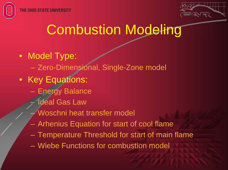
• Model Type:– Zero-Dimensional, Single-Zone model
• Key Equations:– Energy Balance– Ideal Gas Law– Woschni heat transfer model– Arhenius Equation for start of cool flame– Temperature Threshold for start of main flame– Wiebe Functions for combustion model
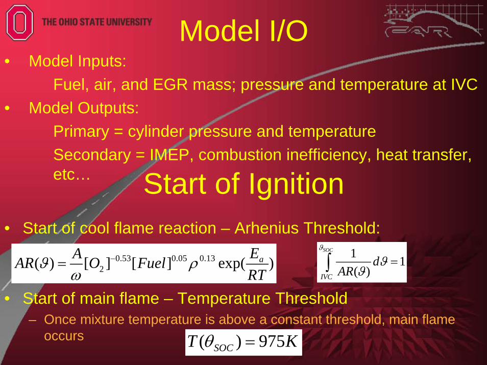
• Start of cool flame reaction – Arhenius Threshold:
• Start of main flame – Temperature Threshold– Once mixture temperature is above a constant threshold, main flame
occurs
0.53 0.05 0.132( ) [ ] [ ] exp( )aEAAR O Fuel
RTϑ ρ
ω−=
1 1( )
SOC
IVC
dAR
ϑ
ϑϑ
=∫
KT SOC 975)( =θ
• Model Inputs: Fuel, air, and EGR mass; pressure and temperature at IVC
• Model Outputs: Primary = cylinder pressure and temperatureSecondary = IMEP, combustion inefficiency, heat transfer, etc… Start of Ignition
Model I/O
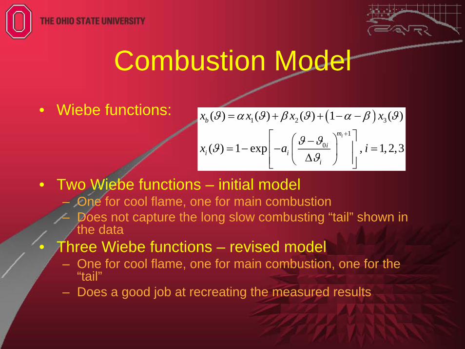
Combustion Model• Wiebe functions:
• Two Wiebe functions – initial model– One for cool flame, one for main combustion– Does not capture the long slow combusting “tail” shown in
the data• Three Wiebe functions – revised model
– One for cool flame, one for main combustion, one for the “tail”
– Does a good job at recreating the measured results
( )1 2 3
1
0
( ) ( ) ( ) 1 ( )
( ) 1 exp , 1, 2,3i
b
m
ii i
i
x x x x
x a i
ϑ α ϑ β ϑ α β ϑ
ϑ ϑϑϑ
+
= + + − −
⎡ ⎤⎛ ⎞−⎢ ⎥= − − =⎜ ⎟∆⎢ ⎥⎝ ⎠⎣ ⎦
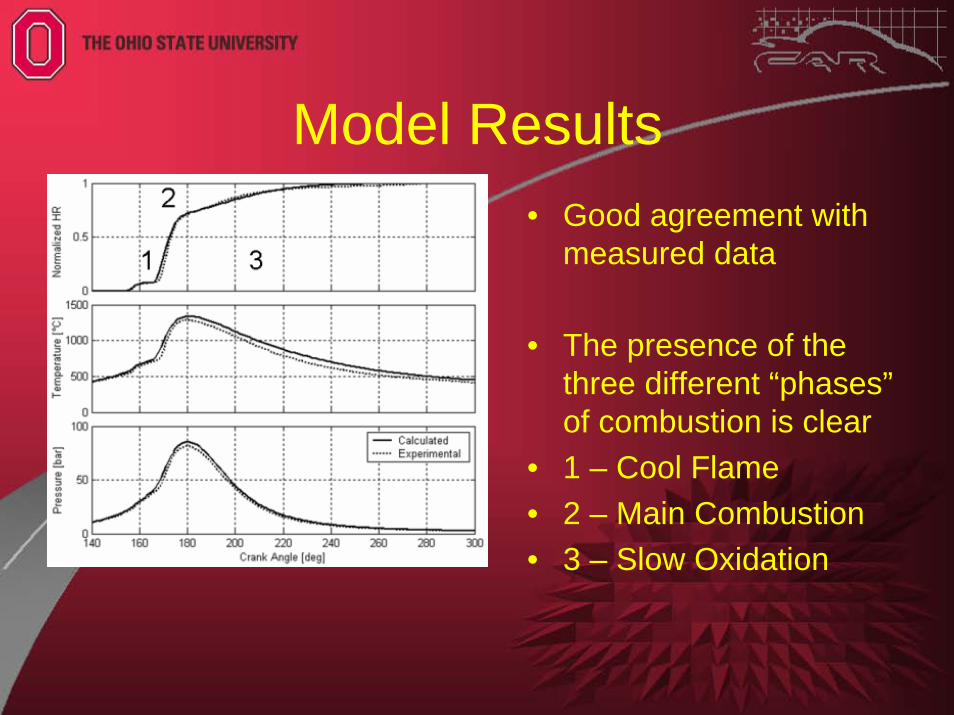
Model Results• Good agreement with
measured data
• The presence of the three different “phases”of combustion is clear
• 1 – Cool Flame• 2 – Main Combustion• 3 – Slow Oxidation
Initial Multi-Cylinder Demo
Atomizer
Intercooler
Intake Manifold
EGR Inlet
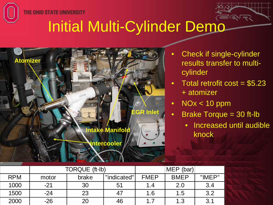
TORQUE (ft-lb) MEP (bar)RPM motor brake "indicated" FMEP BMEP "IMEP"1000 -21 30 51 1.4 2.0 3.41500 -24 23 47 1.6 1.5 3.22000 -26 20 46 1.7 1.3 3.1
• Check if single-cylinder results transfer to multi-cylinder
• Total retrofit cost = $5.23 + atomizer
• NOx < 10 ppm• Brake Torque = 30 ft-lb
• Increased until audible knock
Multi-Cylinder Testing Plans• Just started multi-cylinder engine testing on
2.5 L engine– Upgraded EGR system, variable intercooling, VGT– Cylinder pressure measurements, emissions
measurements, air loop measurements– Look for results in the near future
• Research Goals:– Feed more data into combustion model– Explore methods to control combustion phasing– Explore effect of engine speed on combustion
Why External Diesel HCCI?• As a Research Tool:
– Arguably, it is as homogeneous as you will get with diesel– Allows direct comparison of combustion of other fuels
(gaseous and more volatile fuels) to diesel fuel or other heavy fuels
• As a Commercial Technology: Who Knows?– Requires no modification to DI combustion system - the DI
system stays optimized for DI combustion– Mixed-mode operation is as simple as DI only operation
• Given the success of DI-based HCCI, there is not a clear case for external mixture formation over internal in today’s engines

Today’s Diesel Engine• High Torque * Modest Speed = Acceptable Power
• High Torque operation comes from turbocharging
• Speed limitations in diesels:– Fuel must mix with air for combustion, which is due to
mainly:• Air-Fuel mixing due to injection spray• Air-Fuel mixing due to cylinder motion
– At some engine speed, there simply is not enough time to get the fuel and air mixed and burned near TDC
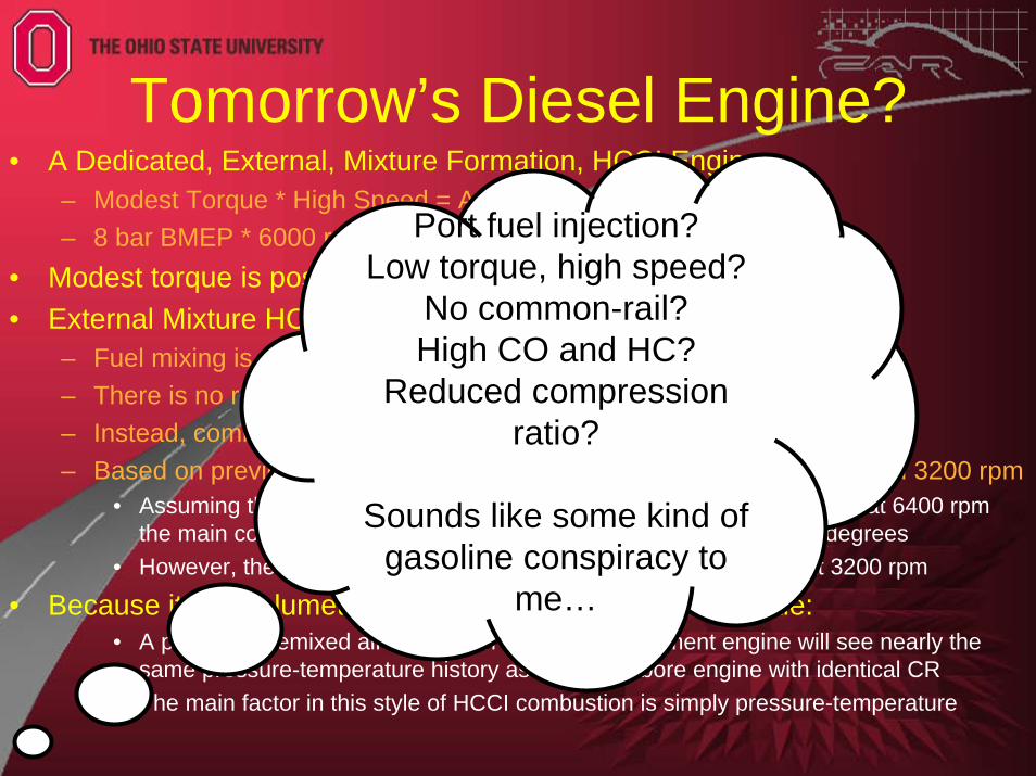
Tomorrow’s Diesel Engine?• A Dedicated, External, Mixture Formation, HCCI Engine
– Modest Torque * High Speed = Acceptable Power– 8 bar BMEP * 6000 rpm = 16 bar BMEP * 3000 rpm
• Modest torque is possible though reduced CR and boosting• External Mixture HCCI Speed Limit???
– Fuel mixing is no longer a problem (unlike DI or internal HCCI)– There is no relevant flame speed (unlike gasoline engines)– Instead, combustion is purely a volumetric reaction– Based on previous figure, combustion looks the same at 1600 rpm and 3200 rpm
• Assuming that this is the limit of combustion speed in the time-domain, at 6400 rpm the main combustion duration would still be on the order of only 40 degrees
• However, there is no indication that the reaction rates are limited at 3200 rpm
• Because it is a volumetric reaction, our results should scale:• A parcel of premixed air and fuel in a large displacement engine will see nearly the
same pressure-temperature history as in a small bore engine with identical CR• The main factor in this style of HCCI combustion is simply pressure-temperature
Port fuel injection?Low torque, high speed?
No common-rail?High CO and HC?
Reduced compression ratio?
Sounds like some kind of gasoline conspiracy to
me…
What Type of Vehicle?• Benefits already demonstrated for series diesels
– Delivery vehicles, city busses, locomotives, ships• Series flexibility allows one to “tame” the HCCI combustion by
controlling transients and speed-load operating points• Potential Benefits:
– Low NOx and PM w/o aftertreatment – even lower w/ aftertreatment– Oxidation of CO and HC possible with current DOC technology– Hybridization gives control over exhaust temperatures – possible to
keep it above catalyst light off temperature– Fuel economy should be acceptable – HCCI may lose some
efficiency, but hybridization could get back to diesel only fueleconomy
• Proof of concept tests could be done simply on a dyno with a CR reduced engine (CR ≈ 16:1)– A series hybrid, is after all, basically a engine on a dynamometer
Contributors• Academic:• Ohio State University (CAR): Prof. Yann Guezennec, Prof.
Giorgio Rizzoni, Marcello Canova, Renaud Garcin, Adam Vosz, David Dumbauld, Shawn Midlam-Mohler
• University of Stuttgart (FKFS): Prof. Michael Bargende, Dr. Hans Jürgen Berner, Simon Haas
• Industry/Government:• Starting a small-scale collaboration with ORNL• We are currently seeking research collaborations in the area of
HCCI combustion.• We are also seeking hardware resources to support our current
academic HCCI research.• Email: [email protected]