Embed Size (px)
Citation preview

OWNER’S MANUAL
MODEL: PW100
Part No.: 852121
Contact your local building or fire officials about obtaining permits, restrictions and installation inspection
requirements in your area.Save these instructions.
United States Stove Company • 227 Industrial Park Road • P.O. Box 151 • South Pittsburg, TN 37380 • www.usstove.comFOR TECHNICAL ASSISTANCE: PHONE: (800) 750-2723 FAX: (423) 837-2129
THIS IS NOT A UL LISTED APPLIANCE
SAFETY NOTICE:If this heater is not properly installed, a house fi re may result. For your safety, follow the installation instructions. Never use make-shift compromises during the installation of this heater. Contact local building or fi re offi cials about permits, restrictions and installation requirements in your area.
CAUTION!Please read this entire manual before you install or use your new room heater. Failure to follow instructions may result in property damage, bodily injury, or even death.Improper Installation Could Void Your Warranty!
2
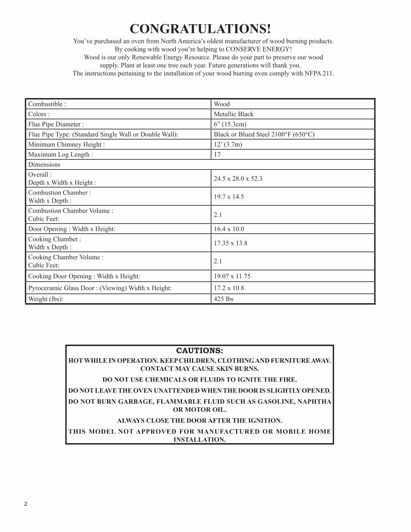
CONGRATULATIONS!You’ve purchased an oven from North America’s oldest manufacturer of wood burning products.
By cooking with wood you’re helping to CONSERVE ENERGY!Wood is our only Renewable Energy Resource. Please do your part to preserve our wood
supply. Plant at least one tree each year. Future generations will thank you.The instructions pertaining to the installation of your wood burring oven comply with NFPA 211.
CAUTIONS:HOT WHILE IN OPERATION. KEEP CHILDREN, CLOTHING AND FURNITURE AWAY.
CONTACT MAY CAUSE SKIN BURNS.DO NOT USE CHEMICALS OR FLUIDS TO IGNITE THE FIRE.
DO NOT LEAVE THE OVEN UNATTENDED WHEN THE DOOR IS SLIGHTLY OPENED.DO NOT BURN GARBAGE, FLAMMABLE FLUID SUCH AS GASOLINE, NAPHTHA
OR MOTOR OIL.ALWAYS CLOSE THE DOOR AFTER THE IGNITION.
THIS MODEL NOT APPROVED FOR MANUFACTURED OR MOBILE HOME INSTALLATION.
Combustible : WoodColors : Metallic BlackFlue Pipe Diameter : 6” (15.3cm)Flue Pipe Type: (Standard Single Wall or Double Wall): Black or Blued Steel 2100°F (650°C)Minimum Chimney Height : 12’ (3.7m)Maximum Log Length : 17DimensionsOverall :Depth x Width x Height : 24.5 x 28.0 x 52.3
Combustion Chamber :Width x Depth : 19.7 x 14.5
Combustion Chamber Volume :Cubic Feet: 2.1
Door Opening : Width x Height: 16.4 x 10.0Cooking Chamber :Width x Depth : 17.35 x 13.8
Cooking Chamber Volume :Cubic Feet: 2.1
Cooking Door Opening : Width x Height: 19.07 x 11.75
Pyroceramic Glass Door : (Viewing) Width x Height: 17.2 x 10.8Weight (lbs): 425 lbs

3
IMPORTANT: Read this entire manual before installing and operating this product. Failure to do so may result in property damage, bodily injury, or even death. Proper installation of this oven is crucial for safe and effi cient operation.
Install vent at clearances specifi ed by the vent manufacturer. Do not connect the vent to a vent serving any other appliance. Do not install a fl ue damper in the exhaust venting system of this unit.
Contact your local building offi cials to obtain a permit and information on any additional installation restrictions or inspection requirements in your area.
Do not throw this manual away. This manual has important operating and maintenance instructions that you will need at a later time. Always follow the instructions in this manual.
This appliance is designed for the use of solid-wood fuel, The use of other fuels will void warranty.
Never use gasoline, gasoline-type lantern fuel, kerosene, charcoal lighter fl uid, or similar liquids to start or ’freshen up’ a fi re in this oven. Keep all such liquids well away from the oven while it is in use.
A working smoke detector must be installed in the same room as this product.
Your oven requires periodic maintenance and cleaning (see ”MAINTENANCE ”). Failure to maintain your oven may lead to improper and/or unsafe operation.
Never try to repair or replace any part of the oven unless instructions for doing so are given in this manual. All other work should be done by a trained technician.
Do not operate your oven with the fuel feed door open. Under these circumstances a safety concern may arise from sparks or fumes entering the room.
Allow the oven to cool before performing any maintenance or cleaning.
Disposal of ashes - Ashes must be disposed in a metal container with a tight fi tting lid. The closed container of ashes should be placed on a non-combustible surface or on the ground, well away from all combustible materials, pending fi nal disposal.
The exhaust system should be checked monthly for any build-up of soot or creosote.
Do not touch the hot surfaces of the oven. Educate all children on the dangers of a high-temperature oven. Young children should be supervised when they are in the same room as the oven.
The oven will be hot during operation; therefore, you should always use some type of hand protection when refueling your oven.
Never block free airfl ow through the open vents of the unit. Do not place clothing or other fl ammable items on or near this oven.
This appliance is not intended for commercial use. Warning: Operate your oven only on a noncombustible fl oor or provide fl ooring protection adequate to provide ember protection around our oven.
SAFETY PRECAUTIONS Creosote-Formation and need for removal. When wood is burned slowly it produces tar and other organic vapors that combine with expelled moisture to form creosote. The creosote vapors condense in a relatively cool fl ue of a slow burning fi re. As a result, creosote residue accumulates on the fl ue lining. When ignited, this creosote makes and extremely hot fi re.
When grease or creosote have accumulated, it should be removed to reduce the risk of fi re.
Do not use accessories not specifi ed for use with this appliance. Verify that the oven is properly installed before fi ring the oven for the fi rst time. After reading these instructions, if you have any doubt about your ability to complete your installation properly, you must obtain the services of a professional licensed installer familiar with all aspects of safe and correct installation. DO NOT use temporary or makeshift compromised during installation. There must be NO DEVIATION OR ALTERATION OF ANY KIND from the very specifi c instructions spelled out in this instruction manual as it pertains to the installation of tis wood oven. NO EXCEPTIONS.
NO NOT ELEVATE THE OVEN BY ANY MEANS. (i.e. Bricks under legs, cement blocks) Oven must set directly upon the solid-surface non-combustible fl oor as specifi ed in this manual.
DO NOT MODIFY THIS OVEN IN ANY WAY! Assemble only with original parts as supplied and shown in this manual. DO NOT OPERATE AN OVEN THAT IS MISSING PARTS! If any parts are missing or defective, please notify the dealer or manufacturer immediately. Replace missing, broken or worn parts with factory original or equivalent parts only.
Do not connect a wood burning appliance to an aluminum type B gas vent. This is not safe. Use approved masonry or a UL listed UL 103HT / ULC-S629 Residential Type and Building Heating Appliance chimney. Use a 6”/152mm diameter chimney, that is high enough to give a good draft. (See specifi cations in the VENTILATION section).
Follow these guidelines to prevent this colorless, odorless gas from poisoning you, your family or others.
Know the symptoms of carbon monoxide poisoning: headache, dizziness, weakness, nausea, vomiting, sleepiness, and confusion. Carbon monoxide reduces the blood’s ability to carry oxygen. Low blood oxygen levels can result in loss of consciousness and death.
See a doctor if you or others develop cold or fl u-like symptoms while cooking or in the vicinity of this appliance. Carbon monoxide poisoning, which can easily be mistaken for a cold or fl ue, is often detected too late.
Alcohol consumption and drug use increase the effects of carbon monoxide poisoning.
Carbon monoxide is especially toxic to mother and child during pregnancy, infants, the elderly, smokers, and people with blood or circulatory system problems, such as anemia, or heart disease.

4
1722
FIRE BOX BRICK LAYOUTCOOKING CHAMBER BRICK LAYOUT
ASSEMBLY
SIDE TABLE (Optional)To install the side table follow the steps below:1. Locate appliance properly as shown.
A) Ensure the appliance is in the final location before installing the side table to reduce possibility of damage.
2. Remove the side table from the packing and check for damage.3. Slide the tabs on the side table into the slots on the side of the
appliance and secure with the three (3) provided 1/2” sheet metal screws as shown.
ASSEMBLY INSTRUCTIONSThis appliance is offered with optional side tables. You must purchase the kit separately from your appliance dealer. Read and
follow instructions in this manual and inside the kit to ensure proper assembly, installation and operation of you new appliance.Caution! The appliance is very heavy.
The assistance from a second person is strongly suggested. Please use proper lifting technic when positioning the appliance for assembly and installation.
Before using your new appliance some assembly is required.1. Check the combustion chamber and cooking chamber for proper brick alignment.2. Install the side table (optional).
FIREBRICK INSTALLATIONThe brick and ash grate for your appliance are installed at the factory. However, the brick may have shifted or moved during
shipping. Ensure the brick is aligned, as shown, with no more than 1/8” (3.2mm) gaps between bricks. If there are broken or cracked bricks please contact your dealer or the manufacturer before using your appliance.
SIDE TABLE ATTACHMENT

5
OVEN INSTALLATION
SAFETY NOTICE• IF THIS OVEN IS NOT PROPERLY INSTALLED, A HOUSE FIRE MAY RESULT. TO REDUCE THE RISK OF
FIRE, FOLLOW THE INSTALLATION INSTRUCTIONS. • CONSULT YOUR MUNICIPAL BUILDING DEPARTMENT OR FIRE OFFICIALS ABOUT PERMITS,
RESTRICTIONS AND INSTALLATIONS REQUIREMENTS IN YOUR AREA.• USE SMOKE DETECTORS IN THE ROOM WHERE YOUR OVEN IS INSTALLED.• KEEP FURNITURE AND DRAPES WELL AWAY FROM THE OVEN.• NEVER USE GASOLINE, GASOLINE-TYPE LANTERN FUEL, KEROSENE, CHARCOAL LIGHTER FLUID,
OR SIMILAR LIQUIDS TO START OR “FRESHEN UP” A FIRE IN THIS HEATER. KEEP ALL SUCH LIQUIDS WELL AWAY FROM THE HEATER WHILE IT IS IN USE.
• IN THE EVENT OF A CHIMNEY FIRE, KEEP THE AIR CONTROL FULL CLOSED TO DEPRIVE THE FIRE OF OXYGEN. CALL THE FIRE DEPARTMENT.
• A SOURCE OF FRESH AIR INTO THE ROOM OR SPACE SHALL BE PROVIDED WHEN REQUIRED.POSITIONING THE OVEN
It is very important to position the wood burning oven as close as possible to the chimney. The oven must never be installed in a hallway or near a staircase, since it may block the way in case of fi re or fail to respect required clearances.
IMPROPER INSTALLATION: The manufacturer will not be held responsible for damage caused by the malfunction of an appliance due to improper venting or installation. Call (800) 750-2723 and/or consult a
professional installer if you have any questions.
INSTALLATION CLEARANCESThe clearances given are minimum dimensions by the NFPA. Installation of this appliance must comply with the latest edition of
NFPA 211 and / or your local building code rulings. Use whichever is largest.Your oven must be installed in residential applications in accordance with the clearances given below. For safety reasons, please
adhere to the installation clearances and restrictions. Clearance to combustibles may NOT be reduced by any means.
PARALLEL INSTALLATION CLEARANCES ANGLED INSTALLATION CLEARANCES SIDE VIEW CLEARANCES
Dimension Inch mmA Backwall to Appliance 36 914B Sidewall to Appliance 36 914C Wall to corner (Angled Installation) 36 914D Ceiling Height 96 2438E Backwall to Flue 18 457F Sidewall to Flue 18 457G Wall to Flue (Angled Installation) 18 457
6
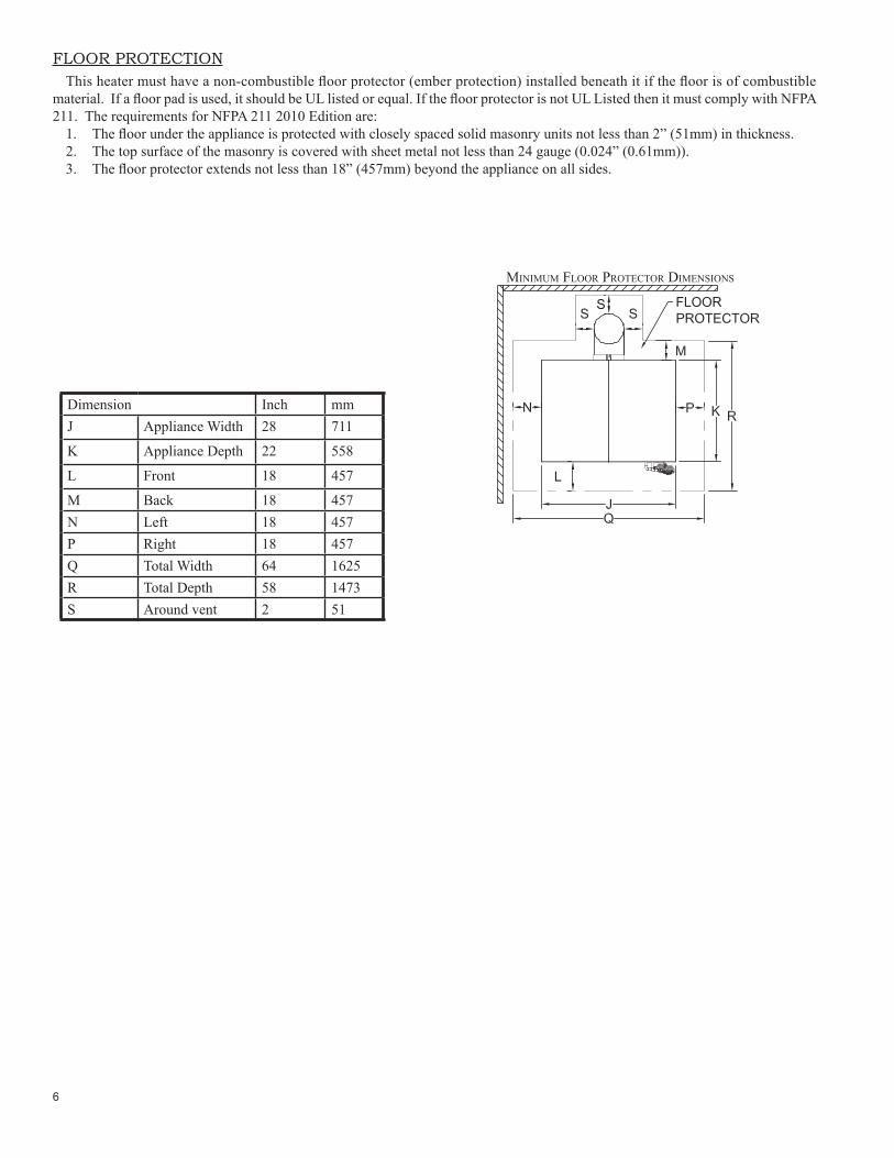
FLOOR PROTECTIONThis heater must have a non-combustible fl oor protector (ember protection) installed beneath it if the fl oor is of combustible
material. If a fl oor pad is used, it should be UL listed or equal. If the fl oor protector is not UL Listed then it must comply with NFPA 211. The requirements for NFPA 211 2010 Edition are:
1. The fl oor under the appliance is protected with closely spaced solid masonry units not less than 2” (51mm) in thickness.2. The top surface of the masonry is covered with sheet metal not less than 24 gauge (0.024” (0.61mm)).3. The fl oor protector extends not less than 18” (457mm) beyond the appliance on all sides.
Dimension Inch mmJ Appliance Width 28 711
K Appliance Depth 22 558
L Front 18 457
M Back 18 457N Left 18 457P Right 18 457Q Total Width 64 1625R Total Depth 58 1473S Around vent 2 51
MINIMUM FLOOR PROTECTOR DIMENSIONS

7
CHIMNEY CONNECTOR (STOVE PIPE)Your chimney connector and chimney must have the same diameter as the appliance outlet (6”). If this is not the case, we recommend
you contact your dealer in order to insure there will be no problem with the draft.The stove pipe must be made of aluminized or cold roll steel with a minimum thickness of 0.021” or 0.53 mm. It is strictly forbidden
to use galvanized steel.Your smoke pipe should be assembled in such a way that the male section (crimped end) of the pipe faces down. Attach each of
the sections to one another with three equidistant metal screws. Seal with furnace cement.The pipe must be short and straight. All sections installed horizontally must slope at least 1/4 inch per foot, with the upper end of
the section toward the chimney. Any installation with a horizontal run of chimney pipe must conform to NFPA 211. You may contact NFPA (National Fire Protection Association) and request the latest edition of the NFPA Standard 211.
To insure a good draft, the total length of the coupling pipe should never exceed 8’ to 10’ (2.4m to 3.04 m). (Except for cases of vertical installation, cathedral-roof style where the smoke exhaust system can be much longer and connected without problem to the chimney at the ceiling of the room).
There should never be more than two 90 degrees elbows in the smoke exhaust system.Installation of a “barometric draft stabilizer” (fi replace register) on a smoke exhaust system is prohibited.Furthermore, installation of a draft damper is not recommended. Indeed, with a controlled combustion wood appliance, the draft
is regulated upon intake of the combustion air in the appliance and not at the exhaust.
ToAppliance
VENTILATION

8
CHIMNEYYour wood appliance may be hooked up with a 6” factory built or masonry chimney. If you are using a factory built chimney,
it must comply with UL 103 or CSA-B365 standard; therefore it must be a Type HT (2100°F). It is extremely important that it be installed according to the manufacturer’s specifi cations.
If you are using a masonry chimney, it is important that it be built in compliance with the specifi cations of the National Building Code. It must be lined with fi re clay bricks, metal or clay tiles sealed together with fi re cement. (Round fl ues are the most effi cient).
The interior diameter of the chimney fl ue must be identical to the appliance smoke exhaust. A fl ue which is too small may cause draft problems, while a large fl ue favours rapid cooling of the gas, and hence the build-up of creosote and the risk of chimney fi res. Note that it is the chimney and not the appliance which creates the draft effect; your appliance’s performance is directly dependent on an adequate draft from your chimney.
The following recommendations may be useful for the installation of your chimney:1. Do not connect this unit to a chimney fl ue serving another appliance.2. It must rise above the roof at least 3’ (0.9m) from the uppermost point of contact.3. The chimney must exceed any part of the building or other obstruction within a 10’ (3.04m) distance by a height of 2’ (0.6m).4. Installation of an interior chimney is always preferable to an exterior chimney. Indeed, the interior chimney will, by defi nition,
be hotter than an exterior chimney, being heated up by the ambient air in the house. Therefore the gas which circulates will cool more slowly, thus reducing the build-up of creosote and the risk of chimney fi res.
5. The draft caused by the tendency for hot air to rise will be increased with an interior chimney.6. Using a fi re screen at the extremity of the chimney requires regular inspection in order to insure that it is not obstructed thus
blocking the draft, and it should be cleaned when used regularly.7. Exterior chimney should be double or triple wall.
9
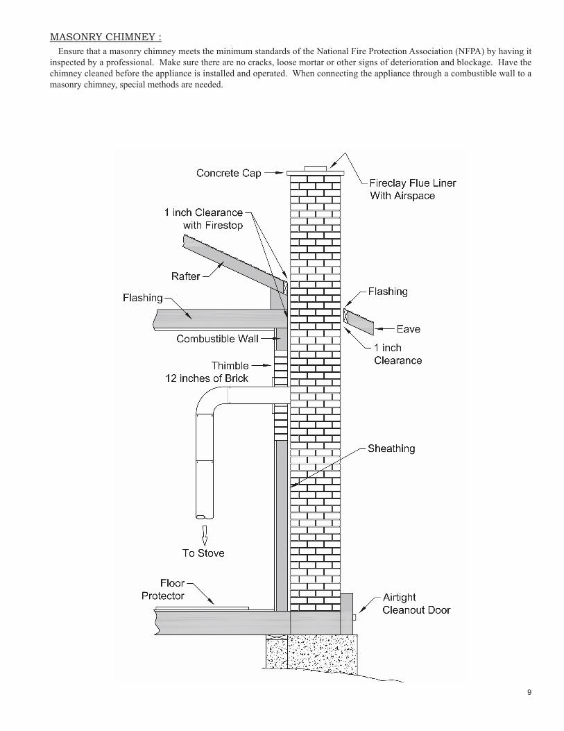
MASONRY CHIMNEY :Ensure that a masonry chimney meets the minimum standards of the National Fire Protection Association (NFPA) by having it
inspected by a professional. Make sure there are no cracks, loose mortar or other signs of deterioration and blockage. Have the chimney cleaned before the appliance is installed and operated. When connecting the appliance through a combustible wall to a masonry chimney, special methods are needed.
10
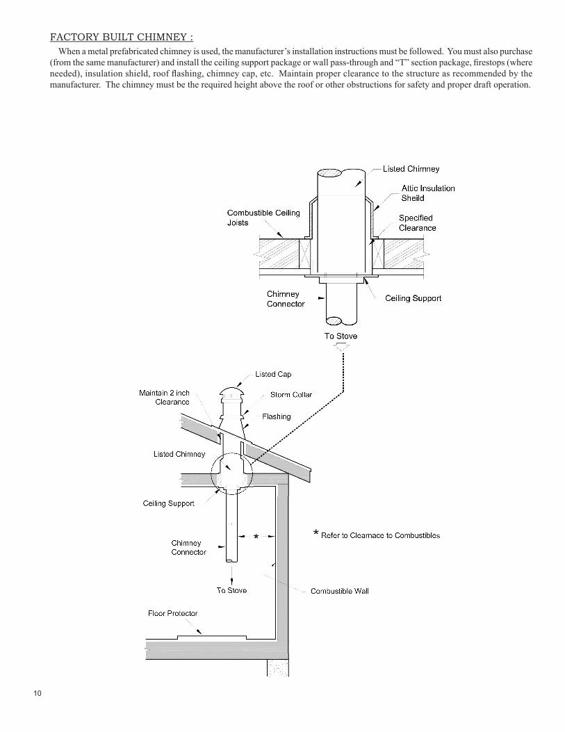
FACTORY BUILT CHIMNEY :When a metal prefabricated chimney is used, the manufacturer’s installation instructions must be followed. You must also purchase
(from the same manufacturer) and install the ceiling support package or wall pass-through and “T” section package, fi restops (where needed), insulation shield, roof fl ashing, chimney cap, etc. Maintain proper clearance to the structure as recommended by the manufacturer. The chimney must be the required height above the roof or other obstructions for safety and proper draft operation.

11
COMBUSTIBLE WALL CHIMNEY CONNECTOR PASS-THROUGHS
Method A. 12” (304.8 mm) Clearance to Combustible Wall Member: Using a minimum thickness 3.5” (89 mm) brick and a 5/8” (15.9 mm) minimum wall thickness clay liner, construct a wall pass-through. The clay liner must conform to ASTM C315 (Standard Specifi cation for Clay Fire Linings) or its equivalent. Keep a minimum of 12” (304.8 mm) of brick masonry between the clay liner and wall combustibles. The clay liner shall run from the brick masonry outer surface to the inner surface of the chimney fl ue liner but not past the inner surface. Firmly grout or cement the clay liner in place to the chimney fl ue liner.
Method B. 9” (228.6 mm) Clearance to Combustible Wall Member: Using a 6” (152.4 mm) inside diameter, listed, factory-built Solid-Pak chimney section with insulation of 1” (25.4 mm) or more, build a wall pass-through with a minimum 9” (228.6 mm) air space between the outer wall of the chimney length and wall combustibles. Use sheet metal supports fastened securely to wall surfaces on all sides, to maintain the 9” (228.6 mm) air space. When fastening supports to chimney length, do not penetrate the chimney liner (the inside wall of the Solid-Pak chimney). The inner end of the Solid-Pak chimney section shall be fl ush with the inside of the masonry chimney fl ue, and sealed with a non-water soluble refractory cement. Use this cement to also seal to the brick masonry penetration.
Method C. 6” (152.4 mm) Clearance to Combustible Wall Member: Starting with a minimum 24 gage (.024” [.61 mm]) 6” (152.4 mm) metal chimney connector, and a minimum 24 gage ventilated wall thimble which has two air channels of 1” (25.4 mm) each, construct a wall pass-through. There shall be a minimum 6” (152.4) mm separation area containing fi berglass insulation, from the outer surface of the wall thimble to wall combustibles. Support the wall thimble, and cover its opening with a 24-gage minimum sheet metal support. Maintain the 6” (152.4 mm) space. There should also be a support sized to fi t and hold the metal chimney connector. See that the supports are fastened securely to wall surfaces on all sides. Make sure fasteners used to secure the metal chimney connector do not penetrate chimney fl ue liner.
Method D. 2” (50.8 mm) Clearance to Combustible Wall Member: Start with a Solid-Pak listed factory built chimney section at least 12” (304 mm) long, with insulation of 1” (25.4 mm) or more, and an inside diameter of 8” (2 inches [51 mm] larger than the 6” [152.4 mm] chimney connector). Use this as a pass-through for a minimum 24-gage single wall steel chimney connector. Keep solid-pak section concentric with and spaced 1” (25.4 mm) off the chimney connector by way of sheet metal support plates at both ends of chimney section. Cover opening with and support chimney section on both sides with 24 gage minimum sheet metal supports. See that the supports are fastened securely to wall surfaces on all sides.
NOTES:1. Connectors to a masonry chimney, excepting method B, shall extend in one continuous section through the wall pass-through
system and the chimney wall, to but not past the inner fl ue liner face.2. A chimney connector shall not pass through an attic or roof space, closet or similar concealed space, or a fl oor, or ceiling.

12
G
VENT TERMINATION CLEARANCES:A) Minimum 4-foot (1.22m) clearance below or beside any door or window that opens.B) Minimum 1-foot (0.3m) clearance above any door or window that opens.C) Minimum 3-foot (0.91m) clearance from any adjacent building.D) Minimum 7-foot (2.13m) clearance from any grade when adjacent to public walkways.E) Minimum 2-foot (0.61m) clearance above any grass, plants, or other combustible materials.F) Minimum 3-foot (0.91m) clearance from an forced air intake of any appliance.G) Minimum 2-foot (0.61m) clearance below eves or overhang.H) Minimum 1-foot (0.3m) clearance horizontally from combustible wall.I) Must be a minimum of 3 foot (0.91m) above the roof and 2 foot (0.61m) above the highest point or the roof within 10
feet (3.05m).
VENT TERMINATION CLEARANCES

13
TYPE WEIGHT(LBS. CU. FT., DRY)
PER CORD EFFICIENCY RANKING
SPLITS MILLIONS BTU’s/CORD
Hickory 63 4500 1.0 Well 31.5
White Oak 48 4100 .9 Fair 28.6
Red Oak 46 3900 .8 Fair 27.4
Beech 45 3800 .7 Hard 26.8
Sugar Maple 44 3700 .6 Fair 26.2
Black Oak 43 3700 .6 Fair 25.6
Ash 42 3600 .5 Well 25.0
Yellow Birch 40 3400 .4 Hard 23.8
Red Maple 38 3200 .3 Fair 22.6
Paper Birch 37 3100 .3 Easy 22.1
Elm/Sycamore 34 2900 .2 Very Diffi cult 20.1
Red Spruce 29 1800 .1 Easy 16.1
OVEN UTILIZATION
It is EXTREMELY IMPORTANT that you use DRY WOOD only in your wood oven. The wood should have dried for 9 to 15 months, such that the humidity content (in weight) is reduced below 20% of the weight of the log. It is very important to keep in mind that even if the wood has been cut for one, two or even more years, it is not necessarily dry, if it has been stored in poor conditions. Under extreme conditions it may rot, instead of drying. This point cannot be over stressed; the vast majority of the problems related to the operation of a wood oven is caused by the fact that the wood used was too damp or has dried in poor conditions. These problems can be:
- Ignition problems- Creosote build-up causing chimney fi res- Low energy yield- Blackened windows- Incomplete log combustionSmaller pieces of wood will dry faster. All logs exceeding 6” in diameter should be split. The wood should not be stored directly
on the ground. Air should circulate through the cord. A 24” to 48” air space should be left between each row of logs, which should be placed in the sunniest location possible. The upper layer of wood should be protected from the elements but not the sides.
TESTING YOUR WOODWhen the oven is thoroughly warmed, place one piece of split wood (about fi ve inches in diameter) parallel to the door on the
bed of red embers.Keep the air control full open by sliding it right and close the door. If ignition of the piece is accomplished within 90 seconds from
the time if was placed in the oven, your wood is correctly dried. If ignition takes longer, your wood is damp.If your wood hisses and water or vapor escapes at the ends of the piece, your wood is soaked or freshly cut. Do not use this wood
in your oven. Large amounts of creosote could be deposited in your chimney, creating potential conditions for a chimney fi re.
Your oven was designed to burn wood only; no other materials should be burned. Waste and other fl ammable materials should not be burned in your oven. Any type of wood may be used in your oven, but specifi c varieties have better energy yields than others. Please consult the following table in order to make the best possible choice.

14
THE FIRST FIRESThe fresh paint on your oven needs to be cured to preserve its quality. Once the fuel charge is properly ignited, only burn small
fi res in your oven for the fi rst four hours of operation. Never open the air control more than necessary to achieve a medium burn rate.Make sure that there’s enough air circulation while curing the oven. The odors may be smelled during the fi rst 3 or 4 fi res. During
curing people and animals with lung problems should take caution.
IGNITIONAft er making sure that the oven air intake controls are fully open (completely slide to the right), place several rumpled sheets of
paper in the center of the combustion chamber. Place 8 to 10 pieces of small dry kindling wood over the paper in the form of a tent. You may also place a few pieces of cooking wood, but choose the smaller ones. No chemical product should be used to light the fi re.
Before igniting the paper and kindling wood, it is recommended that you warm up the chimney. This is done in order to avoid back draft problems often due to negative pressure in the house. If such is the case, open a window slightly near the oven and twist together a few sheets of newspaper into a torch. Light up this paper torch and hold it as close as possible to the back of the combustion chamber to warm up the chimney. Once the updraft movement is initiated, you are ready to ignite the oven by lighting the paper and kindling wood inside the combustion chamber.
When you have achieved a good bed of hot embers, we recommend the following burn procedures:
COOKINGControlled combustion is the most effi cient technique for wood cooking because it enables you to select the type of combustion
you want for each given situation. The wood will burn slowly if the combustion air intake control is adjusted to reduce the oxygen supply in the combustion chamber to a minimum. On the other hand, wood will burn quickly if the air control is adjusted to admit a larger quantity of oxygen in the combustion chamber. Real operating conditions may give very different results than those obtained during testing according to the species of wood used, its moisture content, the size and density of the pieces, the length of the chimney, altitude and outside air temperature.
DAMPERSThe oven has two air control dampers. The lower damper controls the Primary combustion air into the combustion chamber. The
upper air damper controls the air wash across the combustion chamber window as well as allowing additional combustion air to enter the fi rebox. It is recommended that the air wash damper be adjusted so that the window remains free of soot buildup. Then, adjust the primary air damper to control the fi re.
CAUTION: Never alter the damper slide or the adjustment range to increase fi ring for any reason. Doing so could result in oven damage and will void your warranty.

15
WARNINGSNEVER OVERFIRE YOUR OVEN. IF ANY PART OF THE OVEN STARTS TO GLOW RED, OVER FIRING IS
HAPPENING. READJUST THE AIR INTAKE CONTROL AT A LOWER SETTING.THE INSTALLATION OF A LOG CRADLE or GRATES IS NOT RECOMMENDED IN YOUR WOOD OVEN. BUILD
FIRE DIRECTLY ON FIREBRICK.NEVER PUT WOOD ABOVE THE FIREBRICK LINING OF THE FIREBOX.
RELOADINGOnce you have obtained a good bed of embers, you should reload the unit. In order to do so, open the air controls to maximum
a few seconds prior to opening the oven’s door. Then proceed by opening the door very slowly; open it one or two inches for 5 to 10 seconds, before opening it completely to increase the draft and thus eliminate the smoke which is stagnant in a state of slow combustion in the oven. Then bring the red embers to the front of the oven and reload the unit.
For optimal operation of your wood oven, we recommend you to operate it with a wood load approximately equivalent to the height of fi re bricks.
It is important to note that wood combustion consumes ambient oxygen in the room .In the case of negative pressure, it is a good idea to allow fresh air in the room, either by opening a window slightly or by installing a fresh air intake system on an outside wall.
Creosote - Formation and Need for Removal - When wood is burned slowly, it produces tar and other organic vapors, which combine with expelled moisture to form creosote. The creosote vapors condense in the relatively cool chimney fl ue of a slow-burning fi re. As a result, creosote residue accumulates on the fl ue lining. When ignited this creosote makes an extremely hot fi re. The chimney connector and chimney should be inspected at least once every two months during the season to determine if a creosote build-up has occurred. If creosote has accumulated (3mm or more), it should be removed to reduce the risk of a chimney fi re.
We strongly recommend that you install a magnetic thermometer on your smoke exhaust pipe, approximately 18” above the oven. This thermometer will indicate the temperature of your gas exhaust fumes within the smoke exhaust system. The ideal temperature for these gases is somewhere between 275°F and 500°F. Below these temperatures, the build-up of creosote is promoted. Above 500 degrees, heat is wasted since a too large quantity is lost into the atmosphere.TO PREVENT CREOSOTE BUILD UP• Always burn dry wood. This allows clean burns and higher chimney temperatures, therefore less creosote deposit.• Leave the air control full open for about 5 min. every time you reload the oven to bring it back to proper operating
temperatures. • Always check for creosote deposit once every two months and have your chimney cleaned at least once a year.If a chimney or creosote fi re occurs, close all dampers immediately. Wait for the fi re to go out and the oven to cool, then inspect the chimney for damage. If no damage results, perform a chimney cleaning to ensure there is no more creosote deposits remaining in the chimney.
ASH DISPOSALAshes should be removed from the oven every few days or when ashes get to 2 to 3 inches deep. Always empty the oven when
it is cold, such as in the morning. Ashes should be placed in a metal container with a tight fi tting lid. The closed container of ashes should be placed on a non combustible fl oor or on the ground, well away from all combustible materials, pending fi nal disposal. If the ashes are disposed of by burial in soil or otherwise locally dispersed, they should be retained in the close container until all cinders have thoroughly cooled. Other waste shall not be placed in this container.
CAUTIONS:• ASHES COULD CONTAIN HOT EMBERS EVEN AFTER TWO DAYS WITHOUT OPERATING THE OVEN.• THE ASH PAN CAN BECOME VERY HOT. WEAR GLOVES TO PREVENT INJURY.• NEVER BURN THE OVEN WITH THE ASH TRAP OPEN. THIS WOULD RESULT IN OVER FIRING THE
OVEN. DAMAGE TO THE OVEN AND EVEN HOUSE FIRE MAY RESULT.
16
MAINTENANCE
GLASS• Inspect and clean the glass regularly in order to detect any cracks. If you spot one, turn the oven off immediately. Do not abuse
the glass door by striking or slamming shut. Do not use the oven if the glass is broken.• If the glass on your oven breaks, replace only with the glass supplied from your dealer. Never substitute other materials for the
glass.• To replace the glass, remove the screws retaining the glass mouldings inside the door.
1) Remove the mouldings and replace the damaged piece with a new one. 2) Perform the procedure backwards after replacing. When replacing the glass, you should change the glass gasket to make
sure you keep it sealed.• Never wash the glass with a product that may scratch. Use a specialized product, available in the stores where wood ovens are
sold. The glass should be washed only when cold.
GASKETINGIt is recommended that you change the door gasket (which makes your oven door air tight) once a year, in order to insure good
control over the combustion, maximum effi ciency and security. To change the door gasket, simply remove the damaged one. Carefully clean the available gasket groove, apply a high temperature silicone sold for this purpose, and install the new gasket. You may light up your oven again approximately 24 hours after having completed this operation.
Your wood oven is a high effi ciency oven and therefore requires little maintenance. It is important to perform a visual inspection of the oven every time it is emptied, in order to insure that no parts have been damaged, in which case repairs must be performed immediately. Inspect and clean the chimney and connector pipe periodically for creosote buildup or obstructions.
WARNING:NEVER OPERATE THE OVEN WITHOUT A GASKET OR WITH A BROKEN ONE. DAMAGE TO THE OVEN OR
EVEN HOUSE FIRE MAY RESULT.
PAINTOnly clean your oven with a dry soft cloth that will not harm the paint fi nish. If the paint becomes scratched or damaged, it is
possible to give your wood oven a brand new look, by repainting it with a 1200° F heat resistant paint. For this purpose, simply scrub the surface to be repainted with fi ne sand paper, clean it properly, and apply two (2) thin coats of paint successively.
COOKING CHAMBER BRICKThe fi re brick in the cooking chamber is very porous and may absorb any cleaning chemicals used. For this reason, we recommend
placing the cooking chamber fi re brick in the combustion chamber and lighting a small fi re to clean the fi re brick. Doing this will burn off any food particulates and sanitize the brick for further use.

17
SEASONAL START UPPrior to starting the fi rst fi re of the heating season, check the outside area around the exhaust and air intake systems for obstructions.
Clean and remove any fl y ash from the exhaust venting system. Clean any screens on the exhaust system and on the outside air intake pipe. Turn all of the controls on and make sure that they are working properly. This is also a good time to give the entire appliance a good cleaning throughout.
SEASONAL SHUTDOWN The exhaust system should be thoroughly cleaned. REMOVE ANY ASH OR UNBURNED WOOD. CLEAN COOKING CHAMBER
MAINTENANCE SCHEDULEUse the following as a guide under average use conditions.Gaskets around door and door glass should be inspected and repaired or replaced when necessary.
Daily Weekly Monthly or as neededCombustion Chamber BrushedAshes Check EmptyInterior Chambers VacuumedVent System CleanedGaskets InspectedGlass Wiped Cleaned

18
When your appliance acts out of the ordinary, the fi rst reaction is to call for help. This guide may save time and money by enabling you to solve simple problems yourself. Problems encountered are often the result of only fi ve factors.
1. Poor fuel; 2. Poor operation or maintenance; 3. Poor installation; 4. Component failure; 5. Factory defect. You can usually solve those problems related to 1 and 2. Your dealer can solve problems relating to 3, 4 and 5. Refer to diagrams
on page 17 to help locate indicated partsNever try to repair or replace any part of the oven unless instructions for doing so are given in this manual. All other work should
be done by a trained technician.
TROUBLE SHOOTING GUIDE
SMOKE SMELL COMING BACK INTO THE HOMEPossible Causes: Possible Remedies: 1. There is a leak in the vent pipe system. Inspect all vent pipe connections. Make sure they are sealed
with RTV silicone that has a temperature rating on 500 degree F or higher. Also, seal joints with UL-181-AP foil tape. Also, make sure the square to round adapter piece on the combustion blower has been properly sealed with the same RTV.
Because it is a wood-burning device, your oven may emit a faint wood-burning odor. If this increases beyond normal, or if you notice an unusual soot build-up on walls or furniture, check your exhaust system carefully for leaks. All joints should be properly sealed. Also clean your appliance, following instructions in “MAINTENANCE”. If problem persists, contact your dealer.
• GLASS “SOOT’S” UP AT A VERY FAST RATE• FLAME IS LAZY, DARK, AND HAS BLACK TIPS
Possible Causes: Possible Remedies:1. Appliance or vent pipe is dirty, which restricts airfl ow. Follow all cleaning procedure in the maintenance section of
the owner’s manual.2. Vent pipe installed improperly. Check to make sure the vent pipe has been installed according
to the criteria in the owner’s manual.3. Air damper is set too far left (closed) for a higher setting. Slide the damper knob farther right and try to burn the unit
again.5. Air damper is broken. Visually inspect the damper assembly. Make sure the damper
plate is attached to the damper rod. When the damper rod is moved the plate should move with it.
6. Blockage in air intake pipe. Visually inspect the air intake pipe that leads into the burnpot for foreign material.
19
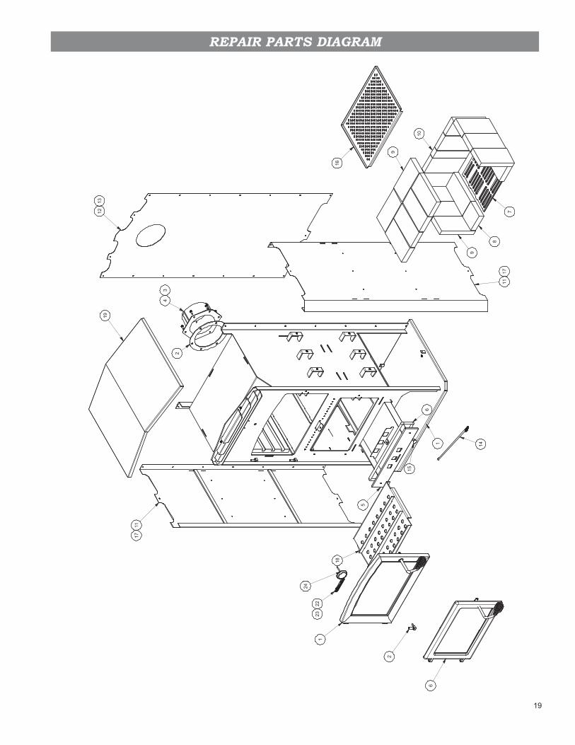
REPAIR PARTS DIAGRAM
1912
13
1117
1
6
5
1
1117
9
16
8
7
18
2223
14
43
2
2
6
15
9
10
24

20
REPAIR PARTS LIST
Key Part No. Description Qty.1 69876 Main Weldment 12 88032 Gasket, Flue Collar 13 83339 1/4-20 X 3/4 Hex Bolt 64 40246 Flue Collar, 6" C.i. 15 69888 Ash Pan 16 88057 Thermocord 1/2 17 40076 Grate, Cast Iron 18 24103 Firebrick, Half (4-1/2 X 4-1/2) 29 89066 Firebrick (4-1/2 X 9) 1810 891414 Half Firebrick 111 69884 Wrapper, Side 212 26461 Side Wrapper, Back 113 83343 #10X1/2 Hx Hd Dp Ox Black 2014 69890 Adjusting Rod 115 891987 Plastic Knob 216 26457 Rack, Pizza Tray 117 83134 1/2 Inch Truss Head Tap Screw 1518 69885 Baffl e, Burn Chamber 119 69889 Wrapper Top Weldment 120 69887 Door Assembly (Cooking Chamber) 121 69886 Door Assembly (Burn Chamber) 122 851713 Logo, Homcomfort 123 83550 Pushnut Fastener (.125 Dia. Stud) 224 80653 Thermometer, 100-900° Stove 1
IN ORDER TO MAINTAIN WARRANTY, COMPONENTS MUST BE REPLACED USING ORIGINAL MANUFACTURERS PARTS PURCHASED THROUGH YOUR DEALER OR DIRECTLY FROM THE
APPLIANCE MANUFACTURER. USE OF THIRD PARTY COMPONENTS WILL VOID THE WARRANTY.
21
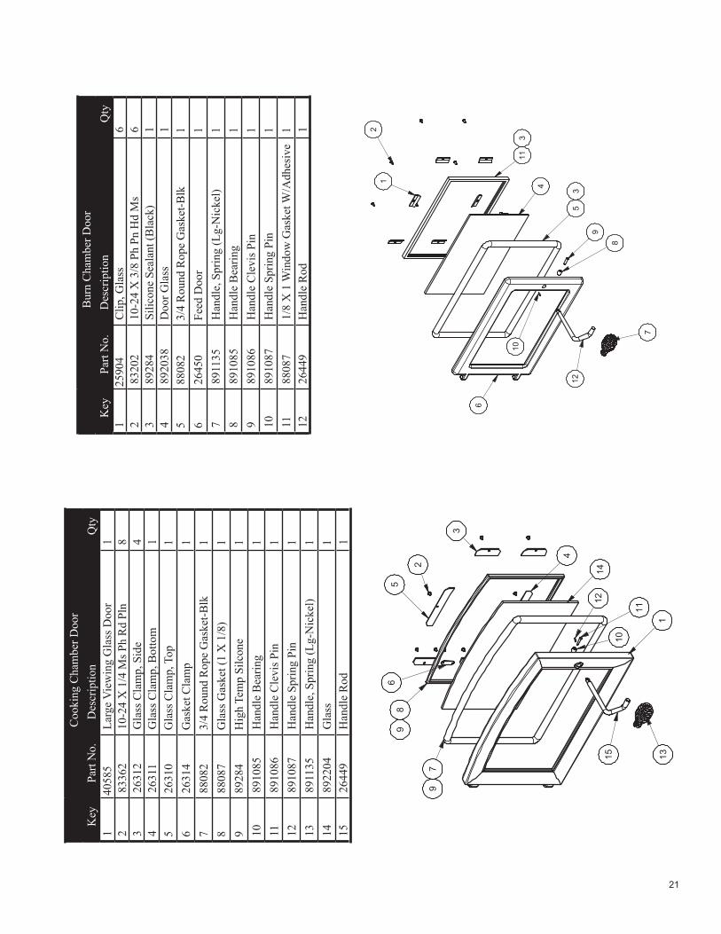
Bur
n C
ham
ber D
oor
Key
Part
No.
Des
crip
tion
Qty
.1
2590
4C
lip, G
lass
62
8320
210
-24
X 3
/8 P
h Pn
Hd
Ms
63
8928
4Si
licon
e Se
alan
t (B
lack
)1
489
2038
Doo
r Gla
ss1
588
082
3/4
Rou
nd R
ope
Gas
ket-B
lk1
626
450
Feed
Doo
r1
789
1135
Han
dle,
Spr
ing
(Lg-
Nic
kel)
18
8910
85H
andl
e B
earin
g1
989
1086
Han
dle
Cle
vis P
in1
1089
1087
Han
dle
Sprin
g Pi
n1
1188
087
1/8
X 1
Win
dow
Gas
ket W
/Adh
esiv
e1
1226
449
Han
dle
Rod
1 21
113
4
53
6
12
9
10
8
7
Coo
king
Cha
mbe
r Doo
rK
eyPa
rt N
o.D
escr
iptio
nQ
ty.
140
585
Larg
e V
iew
ing
Gla
ss D
oor
12
8336
210
-24
X 1
/4 M
s Ph
Rd
Pln
83
2631
2G
lass
Cla
mp,
Sid
e4
426
311
Gla
ss C
lam
p, B
otto
m1
526
310
Gla
ss C
lam
p, T
op1
626
314
Gas
ket C
lam
p1
788
082
3/4
Rou
nd R
ope
Gas
ket-B
lk1
888
087
Gla
ss G
aske
t (1
X 1
/8)
19
8928
4H
igh
Tem
p Si
lcon
e1
1089
1085
Han
dle
Bea
ring
111
8910
86H
andl
e C
levi
s Pin
112
8910
87H
andl
e Sp
ring
Pin
113
8911
35H
andl
e, S
prin
g (L
g-N
icke
l)1
1489
2204
Gla
ss1
1526
449
Han
dle
Rod
1
5
2
89
6
14
11315
11
10
12
79
3
4

22

23
NOTES

24
This manual will help you obtain effi cient, dependable service from your Oven, and enable you to order repair parts correctly.
Keep this manual in a safe place for future reference.
When writing, always give the full model number which is on the nameplate attached to the oven.
When ordering repair parts, always give the following information as shown in this list:
227 Industrial Park RoadP.O. Box 151
South Pittsburg, TN 37380(800) 750-2723
www.usstove.com
HOW TO ORDER REPAIR PARTS
1. The part number ___________________________________________
2. The part description ___________________________________________
3. The model number: ___________________________________________
4. The serial number:___________________________________________

25
Warranty Registration FormPlease take a moment and properly register your new stovewithin 10 days of purchase by completing this form.You can also complete this form by visiting us at usstove.com
Owner: ____________________________________________________________________
Address:__________________________________________________________________
City:____________________________ State: __________ Zip:______________________
Email Address:______________________________________________________________
Phone: ____________________________________________________________________
Dealer/Store:________________________________________________________________
City:____________________________ State: __________ Zip:______________________
Stove Model: ________________________________________________________________
Serial Number:______________________________________________________________
Date Purchased: ____________________________________________________________
Date Installed: ______________________________________________________________
PLEASE COMPLETE THE SURVEY BELOW:How do you currently heat your home?
Electric Natural Gas Propane Heating Oil Wood Pellet
How did you hear about United States Stove Company?Internet Local Store Dealer Friends/Relatives Trade Show
Other: ________________________________________________________________
What were your reasons for selecting one of our products? (check all that apply)Convenience Salesperson Appearance Price Heating Bill SavingsPerformance Add On Quality
Where is your hearth appliance installed?Living Room Family Room Den/Office Bedroom Sun RoomOutdoor Kitchen Bath Masonry Fireplace
Were you satisfied with the service of the dealer/store? YES NO
Did you find the unit you were looking for? YES NO
May we contact you regarding your dealer, your purchase or your unit? YES NO
Please rate your dealer/store on the following:Product Knowledge Excellent Good Fair PoorGeneral Attitude Excellent Good Fair PoorOverall Service Excellent Good Fair Poor
PLEASE SEAL WITH CLEAR TAPE BEFORE MAILING

26
______________________
______________________
______________________
United States Stove Company227 Industrial Park RoadSouth Pittsburg, TN 37380Attn: Registration Form
PLACESTAMPHERE
PLEASE SEAL WITH CLEAR TAPE BEFORE MAILING851997