Embed Size (px)
Citation preview

poolLUX PowerpLX-PW60 & pLX-PW100
Installation InstructionsRead all instructions before attempting to perform installation work
Type 3R Rainproof Enclosure
FOR USE WITH POOL AND SPA PRODUCTS
5005508
ETL LISTEDConforms to UL STD 379;
Certifi .ed .to .CSA .STD .C22 .2 .#218 .1
79-15265-00 .Rev .B

2
ContentsIMPORTANT SAFETY INFORMATION . . . . . . . . . . . . . . . . . . . . . . . . . . . . . . . . .3
Electrical Ratings . . . . . . . . . . . . . . . . . . . . . . . . . . . . . . . . . . . . . . . . . . . . . . . . . . . . . . . . .4
Recommended Tools and Supplies . . . . . . . . . . . . . . . . . . . . . . . . . . . . . . . . . . . . . . .4
INSTALLATION INSTRUCTIONS . . . . . . . . . . . . . . . . . . . . . . . . . . . . . . . . . . . . . . .5
Enclosure Mounting . . . . . . . . . . . . . . . . . . . . . . . . . . . . . . . . . . . . . . . . . . . . . . . . . . . . .5
Input / Supply Line Voltage . . . . . . . . . . . . . . . . . . . . . . . . . . . . . . . . . . . . . . . . . . . . . . .7
Output Wiring for Lights and Light Sources . . . . . . . . . . . . . . . . . . . . . . . . . . . . .8
OPERATING INSTRUCTIONS . . . . . . . . . . . . . . . . . . . . . . . . . . . . . . . . . . . . . . . . 10
Manual Rocker Switch Operation . . . . . . . . . . . . . . . . . . . . . . . . . . . . . . . . . . . . . . 10
WIRING DIAGRAM . . . . . . . . . . . . . . . . . . . . . . . . . . . . . . . . . . . . . . . . . . . . . . . . . . . . 11
REPLACEMENT PARTS . . . . . . . . . . . . . . . . . . . . . . . . . . . . . . . . . . . . . . . . . . . . . . . 12

3
I M P O R T A N T S A F E T Y I N F O R M A T I O N
CAUTION: POWER AND SIGNAL OUTPUT CONDUITS MUST BE NON-METALLIC
ATTENTION: CONDUITS POUR PUISSANCE DE SORTIE ET SORTIE SIGNAL DOIT ETRE NON METALLIQUE
ELECTRICAL SHOCK HAZARD – SWITCH DOES NOT TURN OFF INPUT POWER.Failure .to .disconnect .input .power .before .servicing .can .lead .to .serious .injury, .or .death .
Disconnect .input .power .before .servicing .
Replace all parts and panels before reconnecting power and operating
DANGER – FAILURE TO FOLLOW THESE WARNINGS, INSTRUCTIONS, AND THE OWNER’S MANUAL MAY RESULT IN SERIOUS INJURY OR DEATH.
Basic .safety .precautions .shall .be .observed .when .installing .and .operating .the .poolLUX .Power . (p/n .pLX-PW60/PW100) .and .other .associated .equipment:
1 . . A .qualified .electrician .must .install .the .poolLUX .Power .(p/n .pLX-PW60/PW100) .in .accordance .with .the .requirements .of .NEC .ANSI/NFPA .70 .and .Article .680 .
2 . . The .poolLUX .Power .(p/n .pLX-PW60/PW100) .must .be .mounted .on .a .flat .vertical .surface . .The .unit .must .be .a .minimum .of .4 .inches .above .the .ground .level, .pool .deck, .or .higher .than .8 .inches .above .the .maximum .pool .water .level, .whichever .provides .greatest .elevation . . .The .unit .must .be .positioned .a .minimum .of .4 .feet .(1 .2 .m) .away .from .the .inside .wall .of .the .pool, .unless .separated .from .the .pool .by .a .solid .fence, .wall, .or .other .permanent .barrier .
3 . . CAUTION: .THE .EQUIPMENT .AND .CONTROLS .SHALL .BE .LOCATED .NOT .LESS .THAN . 1 .M .HORIZONTALLY .FROM .THE .SPA .OR .HOT .TUB .
4 . . ATTENTION: .MAINTENIR .UNE .DISTANCE .MINIMALE, .MESURÉE .DANS .UN .PLAN .HORIZONTAL, .DE .1 .M .ENTRE .LA .CUVE .DE .RELAXATION .ET .LES .APPAREILS .ET .COMMANDES .
5 . . ONLY .USE .COPPER .CONDUCTORS .
6 . . Do .not .exceed .the .maximum .electrical .ratings .of .the .poolLUX .Power .(p/n .pLX-PW60/PW100) .components .(indicated .on .page .4), .wiring .devices, .and .current .carrying .capacity .of .the .conductors .
7 . . poolLUX .Power .(p/n .pLX-PW60/PW100) .is .intended .to .be .used .with .low .voltage .underwater .luminaires .that .comply .with .Article .680 .of .the .National .Electrical .Code .and .does .not .require .bonding .due .to .their .polymeric .or .isolated .application .design .
8 . . This .device .should .never .operate .equipment .that .could .cause .property .damage, .bodily .injury, .or .death .should .it .be .activated .unexpectedly .
9 . . Use .with .branch .circuit .breakers .with .15 .amperes .or .less .
10 . . This .device .must .be .used .with .an .approved .ground-fault .circuit .interrupter .(GFCI) . .
11 . . Use .rain-tight .or .wet .location .hubs .that .comply .with .the .requirements .in .the .standard .(UL514b) .for .conduit, .tubing, .and .cable .fittings .only .
12 . . The conduit hub is to be connected to the power input conduit before the hub is connected to the .enclosure .
13 . . Never .allow .children .to .operate .the .pLX-Power .unit .unsupervised .

4
E l e c t r i c a l R a t i n g s
Do .not .exceed .the .maximum .electrical .output .rating .of .each .unit .listed .below . .
Model Input Output pLX-PW60 . 120 .VAC, .60 .Hz, .0 .6A .max . 12-13 .VAC, .60 .Watt .maxpLX-PW100 . 120 .VAC, .60 .Hz, .1 .0A .max . 12-13 .VAC, .100 .Watt .max
Use .a .15 .Amp, .120VAC .GFCI .Circuit .Breaker .for .input .power . .
Thermal CutoffsTo .help .protect .against .undesirable .thermal .conditions, .the .poolLUX .Power .(p/n .pLX-PW60/PW100) .utilizes .thermal .cutoffs .that .will .stop .electricity .in .the .event .of .an .overload, .or .overheat .condition . .When .the .fault .condition .is .rectified, .the .output .power .will .self-reset .without .user .intervention .
Output FuseTo .protect .against .hazardous .electrical .conditions, .the .poolLUX .Power .(p/n .pLX-PW60/PW100) .utilizes .a .current .fuse .that .will .cut .off .output .electricity .in .the .event .of .a .short .circuit .condition . . .When .the .fault .condition .is .rectified .and .the .fuse .is .replaced, .normal .operation .will .resume . . . Only .use .S .R .Smith .replacement .fuses: .
36-15017-00 .(pLX-PW60) . 36-15018-00 .(pLX-PW100)
R e c o m m e n d e d To o l s a n d S u p p l i e s
1 . . Circular hole saw for installation of 3/4" .and .or .1" non-metallic conduit depending on installation .requirements . .Do not use spade bits for opening the conduit knockouts.
2 . . Application .appropriate .and .approved .‘rain-tight’ .or .‘wet .location’ .conduit .hubs . .
3 . . Additional .duct .seal .may .be .required .for .three .or .more .conduit .installations . * Note: .Every .installation .will .have .at .least .two .conduits .- .one .for .input .power .and .one .for .output .power . .Most .installations .will .likely .have .several .output .power .conduits . .
4 . . Slotted .screwdriver, .size .#2
5 . . Phillips .screwdriver, .size .#2 .
6 . . Drill
7 . . #10 .Screws .appropriate .for .installing .the .product .onto .a .wall .(installer supplied) * Note: It is recommend to hand tighten all screw terminals and screw fasteners inside the enclosure .and .front .cover .until .snug .and .secure . .Be .sure .not .to .overtighten .as .permanent .damage .may .occur .

5
I N S T A L L A T I O N I N S T R U C T I O N S
WARNING• TURN .OFF .INCOMING .POWER .BEFORE .SERVICING .EQUIPMENT .
• ALL .INSTALLATION .AND .MAINTENANCE .WORK .MUST .BE .PERFORMED .BY .A . QUALIFIED .ELECTRICIAN .
• GFCI .BREAKER .MUST .BE .USED .TO .CONNECT .(p/n .pLX-PW60/PW100) .TO .INPUT .POWER .
• VERIFY .ALL .ELECTRICAL .RATINGS .BEFORE .INSTALLATION .IS .COMPLETE .
• FOLLOW PROPER WIRING PRACTICES IN ACCORDANCE WITH ALL NATIONAL AND LOCAL .REGULATORY .REQUIREMENTS .
E n c l o s u r e m o u n t i n g
1 . . Locate .the .poolLUX .Power .(p/n .pLX-PW60/PW100) .in .an .appropriate .area .that .meets .the .following .requirements:
a . .Must .be .mounted .on .a .flat .vertical .surface . . .
b . .Must .be .a .minimum .of .4 .inches .above .the .ground .level, .pool .deck, .or .higher .than .8 .inches .above .the .maximum .pool .water .level, .whichever .provides .greatest .elevation .
c . .Must .be .positioned .a .minimum .of .4 .feet .(1 .2 .m) .from .the .inside .wall .of .the .pool .unless .separated .from .the .pool .by .a .solid .fence, .wall, .or .other .permanent .barrier . .
For .the .unit .to .be .adequately .air .cooled, .allow .a .minimum .gap .of .9/32" .(7 .2mm) .between .the .wall .and .the .back .surface .of .the .unit . .The .stand-off .mounting .tabs .will .make .contact .with .the .wall .
WA
LL
Minimum .Gap .of .9/32" .or .7 .2mm

6
2 . . By .hand, .open .the .enclosure .by .pulling .the .front .cover .off .evenly .by .the .top .and .bottom .tabs . .Do .not .angle .or .‘hinge’ .the .cover .when .removing .or .damage .may .occur . .If .you .cannot .open .the .enclosure .by .hand, .use .a .flat .blade .screwdriver .to .twist .open .the .finger .tabs .of .the .cover .at .the .top .and .bottom .of .the .unit .
3 . . Securely .install .a .wall .material .appropriate .#10 .screw .(Installer .Supplied) .into .the .location .where .the .unit .will .be .installed . .The .screw .head .must .be .1 .1/8” .away .from .the .wall .to .allow .the .unit .to .be .mounted .correctly .
4 . . Place .the .mounting .tab .of .the .poolLUX .Power .(p/n .pLX-PW60/PW100) .over .the .#10 .screw .and .let .it .hang .in .place . .Level .the .unit .and .mark .the .remaining .2 .mounting .screw .locations .on .the .wall . .Use .2 .more .material .appropriate .#10 .screws .(Installer .Supplied) .to .secure .the .unit .to .the .wall .through .the .mounting .holes .on .the .back .of .the .unit . .Once .the .lower .two .screws .are .secure, .tighten .the .top .screw .to .securely .hold .the .upper .portion .of .the .enclosure .in .place .
Top View
Enclosure
Front View
Enclosure
Side View EnclosureRemove .front .cover .by .evenly .pulling .the .top .
and bottom tabsBottom View
Enclosure
Top Tab
. Bottom .Tab

7
I n p u t / S u p p l y L i n e V o l t a g e
1 . . Remove .the .metal .input .voltage .isolation .barrier .by .unscrewing .the .mounting .screw . .Once .the .securing .screw .is .removed, .the .isolation .cover .will .pull .straight .out .to .allow .easier .access .to .the .conduit .knockout .locations .
TRANSFORMER
TRANSFORMER
Metal Input Voltage Isolation Barrier .Mounting .Screw .
Locations of Input Power Knockouts
Locations of Output Power Knockouts
*Note: .Once .all .conduits .are .connected, .replace .the .metal .input .voltage .isolation .barrier .and .mounting .screw . .Tighten .until .the .mounting .screw .is .secure . . .
2 . . Bring .the .supply .power .conduit .to .one .of .the .four, .lower .right .input .power .conduit .knockout .locations .that .terminate .‘inside’ .the .isolation .barrier . .No .output .connections .are .allowed .through .these .knockout .locations . *Note: .The .wiring .of .the .input .and .output .power .are .required .to .use .separate .conduits .and .must .not .share .an .individual .conduit . .No .conduit .should .contain .both .input .and .output .power .wiring .
3 . . Using .a .hole .saw, .open .the .knockouts .for .the .size .of .the .conduit .(¾" .or .1") .being .installed .
ON
OFF
8
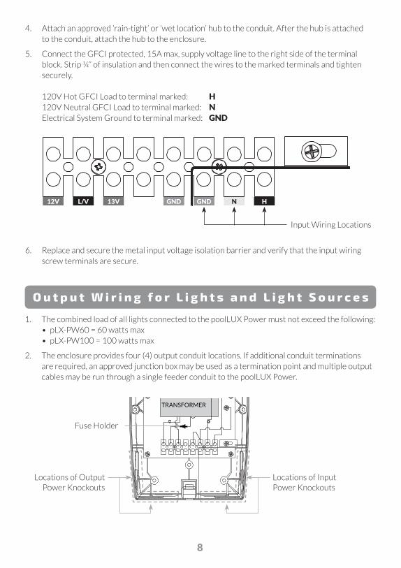
4 . . Attach .an .approved .‘rain-tight’ .or .‘wet .location’ .hub .to .the .conduit . .After .the .hub .is .attached . to .the .conduit, .attach .the .hub .to .the .enclosure .
5 . . Connect .the .GFCI .protected, .15A .max, .supply .voltage .line .to .the .right .side .of .the .terminal .block . .Strip .¼” .of .insulation .and .then .connect .the .wires .to .the .marked .terminals .and .tighten .securely . 120V .Hot .GFCI .Load .to .terminal .marked: . . H 120V .Neutral .GFCI .Load .to .terminal .marked: . N Electrical System Ground to terminal marked: GND
6 . . Replace .and .secure .the .metal .input .voltage .isolation .barrier .and .verify .that .the .input .wiring .screw .terminals .are .secure .
12
VA
C
13
VA
C
PO
WE
R IN
PU
TN
EU
TR
AL
PO
WE
R IN
PU
T
PO
WE
R IN
PU
TG
RO
UN
D
CO
M
GR
OU
ND
GND N H
Input Wiring Locations
O u t p u t W i r i n g f o r L i g h t s a n d L i g h t S o u r c e s
1 . . The .combined .load .of .all .lights .connected .to .the .poolLUX .Power .must .not .exceed .the .following: • . pLX-PW60 .= .60 .watts .max • . pLX-PW100 .= .100 .watts .max
2 . . The .enclosure .provides .four .(4) .output .conduit .locations . .If .additional .conduit .terminations .are .required, .an .approved .junction .box .may .be .used .as .a .termination .point .and .multiple .output .cables .may .be .run .through .a .single .feeder .conduit .to .the .poolLUX .Power .
TRANSFORMER
Locations of Input Power Knockouts
Locations of Output Power Knockouts
GND12V L/V 13V
Fuse Holder

9
12
VA
C
13
VA
C
PO
WE
R IN
PU
TN
EU
TR
AL
PO
WE
R IN
PU
T
PO
WE
R IN
PU
TG
RO
UN
D
CO
M
GR
OU
ND
GNDGND12V NL/V H13V
Output Wiring Locations
3 . . Using .a .hole .saw, .open .the .knockout .for .the .size .of .the .conduit .(¾" .or .1") .being .installed . .
4 . . Bring .output .conduits .to .the .open .conduit .locations . .Any .conduit .used .as .output .wiring .runs .between .the .lights .and .pLX-Power .unit .(p/n .pLX-PW60/PW100) .and .any .external .controller .shall .be .Non-Metallic .(Polymeric) . . ATTENTION: LES CONDUITS DOIVENT ÊTRE RELIÉS PAR LA MASSE
5 . . Attach .an .approved .‘rain-tight’ .or .‘wet .location’ .hub .to .the .conduit .first, .and .then .attach .hub .to .the .enclosure . .
6 . . The .poolLUX .Power .has .has .two .low .voltage .electrical .output .terminals .(Taps) .or .connection .points .that .allow .for .12VAC .or .13VAC .operation . .Securely .connect .the .lights’ .two .conductors .to .the .electrical .(taps) .output .terminals . .Most .installations .will .utilize .the .terminal .configuration .of .12VAC .terminal .and .low .voltage .common .terminal . .In .some .cases .additional .voltage .may .be .required .to .operate .the .lights .requiring .use .of .the .13VAC .terminal .and .the .low .voltage .common .terminal .
*Note: .DO .NOT .use .or .bridge .both .the .12VAC .and .13VAC .terminal .positions .at .the .same .time . .
7 . . Do .a .final .inspection .to .verify .all .wiring .connections .are .correct .
8 . . Once .inspected, .align .the .panel .bayonet .guides .to .the .snap-in .receivers .along .the .centerline .of .the .enclosure . .Evenly .and .gently, .push .the .cover .in .place .ensuring .that .both .the .top .and .bottom .latches .‘snap’ .in .place .
9 . . Apply .power .from .the .input .supply .voltage .to .the .unit .and .function .test .the .unit .via .the .two-way .rocker .switch .on .the .upper, .right .side .of .the .unit .
CAUTION – IF USING FEEDER OR SUPPLY LINES TO A JUNCTION BOX, BE SURE TO USE THE APPROPRIATE WIRE GAUGE FOR THE LOAD AND DISTANCES INVOLVED.
or

10
O P E R A T I N G I N S T R U C T I O N S
M a n u a l R o c k e r S w i t c h O p e r a t i o n
The .poolLUX .Power .comes .with .one .rocker .switch . for .operation . .The .switch .must .be .in .the .OFF .(Down) . position .before .powering .on .for .the .first .time . . To .turn .ON .(Up) .the .12VAC .connected .lights, . flip .the .Rocker .Switch .UP .or .to .the .ON .position . . To .turn .OFF .the .12VAC .connected .lights, .flip .the . Rocker .Switch .to .the .DOWN .or .OFF .position . . .
Color Changing OperationTo change LED pool light colors simply toggle between .the .ON/OFF .position .within .1 .second . of each toggle until the desired color or light show .is .reached . .
WARNING
ELECTRICAL SHOCK HAZARD –SWITCH DOES NOT TURN OFF INPUT POWER.Failure to disconnect input power before servicing can lead to serious injury, or death.Disconnect input power before servicing.Replace all parts and panels before reconnecting power and operating.

11
W I R I N G D I A G R A M
Electrical Connections
NOTES: UNLESS
OTHERWISE SPECIFIED
1 . . WIRE .COLOR .LEGEND:
. R .= .RED
. W .= .WHITE
. BK .= .BLACK
. B .= .BLUE
. Y .= .YELLOW
. G .= .GROUND
2 . . . ELECTRICAL . . .
CONNECTIONS LEGEND:
. 12V .= .12VAC
. . L/V .= . .LOW .VOLTAGE .
COMMON
. 13V .= .13VAC
. GND .= .GROUND
. N .= . .POWER .INPUT .
NEUTRAL
. H .= .POWER .INPUT
TRANSFORMER
12
VA
C
13
VA
C
PO
WE
R IN
PU
TN
EU
TR
AL
PO
WE
R IN
PU
T
PO
WE
R IN
PU
TG
RO
UN
D
CO
M
GR
OU
ND
GND N HGND12V L/V 13V
B R Y G
G
W BK
BK ON
OFF

12
R E P L A C E M E N T P A R T S
Replacement parts for the poolLUX Power (pLX-PW60 or pLX-PW100): Transformer .(pLX-PW60) . . . . . 44-15039-00 . .
Transformer .(pLX-PW100) . . . . 44-15040-00 .
2-Way .Switch . . . . . . 38-15002-00 . .
Isolation .Barrier . . . . . . 02-15342-00 . .
Isolation .Barrier .mounting .screw, .8-32 . . 10-15078-05 . .
Fuse .Holder . . . . . . 36-15016-00
Fuse .(pLX-PW60) . . . . . . 36-15017-00
Fuse .(pLX-PW100) . . . . . 36-15018-00
S .R .Smith, .LLC
P .O . .Box .400 . .| . .Canby, .OR .97013
P .503 .266 .2231 . . .TF .800 .824 .4387
srsmith.com
© .2017 .S .R .Smith . .All .rights .reserved . . .79-15265-00 .Rev .B
Questions? Contact .One .of .Our .Dedicated .Lighting .Specialists . . 1-800-824-4387 x4012 . .or . .x2282