Embed Size (px)
Citation preview

The latest programmable solar array simulator power supply 62000H-S Series released by Chroma provide simulation of Voc (open circuit voltage) up to 1000V and Isc (short circuit current) up to 25A. The 62000H-S provides an industry leading power density in a small 3U high package. The solar array simulator is highly stable and has a fast transient response design, which are both advantageos to MPPT performance evaluation on PV inverter devices.
The 62000H-S Series have many unique advan-tages including high speed & precision digitizing measurement circuits with a 100kHz A/D, 25kHz D/A controlled I-V curve and a digital f i lter mechanism. It can simulate an I-V curve accurately and response the mains ripple e�ect from the PV inverter. In addition, the built-in EN50530/Sandia SAS I-V model in the standalone unit can easily program the Voc, Isc, Vmp, and Imp parameters for I-V curve simulation, without a PC controller.
The real solar array is influenced by various weather conditions such as irradiation, temper-ature, rain and shade by trees or clouds, which will affect the I-V curve output. The 62000H-S Series are capable of storing up to 100 I-V curves into the simulator memory, with a programmed time interval range of 1-15,000 seconds. It can simulate the I-V curve from the early morning to nightfall for PV inverter testing or dynamic I-V curve transient testing.
The 62000H-S Ser ies have a bui l t-in 16 bit digital control and precision voltage & current measurement circuits with a voltage accuracy of 0.05% + 0.05% F.S. and a current accuracy of 0.1% + 0.1% F.S.. It is ideal for real time MPPT analysis and tracking monitoring for PV inverters through our softpanel. The user can also enable the data recording function on the softpanel during the static MPPT performance test.
When high power solar array simulation is required, it is common to connect two or more power modules in parallel. The 62000H-S Series with a current range up to 25A and a voltage range up to 1000V offers a high power density envelope maximum of 15kW in a 3U package. It can easily parallel up to ten units in a Master/Slave configuration to provide 150kW with current sharing and synchronized control signals for commercial utility PV inverter (10kW ~100kW) testing. The 62000H-S Series supplies have a smart Master/Slave control mode that makes the parallel operation fast and simple. In this mode, the master scales values and downloads data to slave units so that the programming is as simple as using a standalone unit.
The 62000H-S Series dc power supplies are very easy to operate from the front panel keypad or from the remote controller via USB/RS232/RS485/APG (standard) and GPIB & Ethernet (optional). Its compact size (3U) makes it ideal for both benchtop and standard racking.
PROGRAMMABLE DC POWER SUPPLY (SOLAR ARRAY SIMULATION)MODEL 62000H-S SERIES
MODEL 62000H-S Series
Key Features :
■ Voltage range : 0 ~150V/600V&1000V■ 3U/15kW high power density module with easy master/slave parallel operation up to 1.5MW■ Fast transient response solar array simulation■ Simulation of multiple solar cell material’s I-V characteristic (fill factor)■ Simulation of dynamic irradiation intensity and temperature level from clear day to cloud cover conditions■ Shadowed I-V curve output simulation (up to 4096 data points)■ Low leakage current (< 3mA)■ Precision V & I measurements■ Auto I-V program: 100 I-V curves & Dwell time 1-15,000s■ Static & dynamic MPPT efficiency test (accumulated energy methods)■ Data recorded via softpanel■ Standard USB / RS232 / RS485 interface■ Optional GPIB / Ethernet interface■ Real time analysis of PV inverter’s MPPT tracking via softpanel■ Free graphic user interface - softpanel for operation■ Real world weather simulation fast I-V curve update rate : 1s■ Support up to six-channel SAS control for multi-MPPT testing■ Build-in dynamic MPPT test profile of EN50530, Sandia, CGC/GF004 and NB/T 32004
GPIBRS-485APG RS-232 Ethernet USB
Programmable DC Power Supply(Solar Array Simulation)

SOLAR ARRAY I-V CURVE SIMULATION POWER SUPPLY
Solar Array SimulatorUUT (PV Inverter)
DC Voltage Input AC Power Output
The Model 62000H-S Series have a built-in EN50530 and Sandia's SAS model that can easily program the Voc, Isc, Vmp, Imp parameters to simulate different solar cell materials I-V characteristic outputs with fast response time. Moreover, the TABLE mode is capable of saving a 128~4096 point array of user programmed voltages and currents via a remote interface. It can easily create a shadowed I-V curve and the I-V PROGRAM mode can save up to 100 I-V curves and dwell time intervals (1-15,000s) in memory. These advantages provide steady repetitive control conditions required for PV Inverter design as well as for verification testing. The solar array simulator is ideal for the following testing:
SOLAR ARRAY I-V CURVE SIMULATION SOFTPANEL
The model 62000H-S Series include a graphical user Interface software through remote digital interface (USB / GPIB / Ethernet / RS232) control. The user can easily program the I-V curve of the 62000H-S Series as well as the I-V & P-V curves for real-time testing. In addition it will display the MPPT status for the PV inverter. Readings and the report function with real-time monitoring using the softpanel are shown left.
SIMULATES DIFFERENT SOLAR CELL MATERIALS I-V CHARACTERISTIC(FILL FACTOR)The purpose of the PV inverter is to convert the dc voltage (from solar array) to the ac power (utility). The better a PV inverter can adapt to the various irradiation & temperature conditions of sun, the more power that can be fed into the utility grid over time. So, the MPPT performance is a very important factor for PV generation system. The model 62000H-S Series are capable of simulating different types of standard crystalline, multi-crystalline and thin-film fill factor* parameters to verify the MPPT tracking algorithm mechanism and efficiency.*Fill Factor = (Imp*Vmp)/(Isc*Voc)
Solar Array Simulation Softpanel
■ Design and verify the maximum power tracking circuit and algorithm of the PV inverter. ■ Verify the high/low limit of operating input voltage allowed for the PV inverter. ■ Verify the high/low limit of operating input voltage allowed for the inverter’s maximum power point. ■ Verify the static maximum power point tracking efficiency of the PV inverter. ■ Measure and verify the overall efficiency & conversion efficiency of PV inverter. *
High-efficiency CrystallineStandard Crystalline ArrayThin-Film
FF=0.80FF=0.68FF=0.55
Isc
Vmp Voc
ImpIsc
Voc
Point 1
0
11
2
30
10
3
60
9
4
90
8
5
120
7
6
150
6
7
180
5
128
600
0
.......
.......
.......
Voltage(V)
Current(A)
Isc
Vmp Voc
ImpIsc
Voc
Point 1
0
11
2
30
10
3
60
9
4
90
8
5
120
7
6
150
6
7
180
5
128
600
0
.......
.......
.......
Voltage(V)
Current(A)
SAS Mode I-V Program Mode Table Mode
Isc
Vmp Voc
ImpIsc
Voc
Point 1
0
11
2
30
10
3
60
9
4
90
8
5
120
7
6
150
6
7
180
5
128
600
0
.......
.......
.......
Voltage(V)
Current(A)
■ Verify the maximum power point tracking performance of the inverter for dynamic curves. (EN50530, Sandia, CGC/GF004, NB/T 32004 standard)■ Verify the maximum power point tracking performance of the inverter under different time period conditions spanning from morning to nightfall. ■ Verify the maximum power point tracking mechanism of the inverter for the I-V curve when the solar array is shaded by clouds or trees.■ Simulate the I-V curve under the actual environmental temperatures within burn-in room to do inverter burn-in testing. *Requires an extra power meter.

STATIC MPPT EFFICIENCY TESTINGThe 62150H-600S DC power supply with solar array simulation can program the I-V curve through SAS mode and table mode via front panel or softpanel easily and up to 100 I-V curves can be stored in the unit. The user can recall the I-V curve from 62150H-600S afterwards for testing and monitoring the MPPT performance of PV inverter with the real-time tracking feature. The softpanel allows the user to set the duration for static MPPT efficiency testing. Each curve test time should be set at between 60s-600s for best MPPT efficiency performance analysis.
Vdc = Sampled value of the inverter's input voltage Idc = Sampled value of the inverter's input current Tm = Overall measuring period Pmpp = MPPT power provided by the solar array simulator power supply
ηMPPT =1
Pmpp ● TMΣVdc ● Idc ● ΔT
DYNAMIC MPPT EFFICIENCY TESTINGThe latest test standards EN50530, CGC/GF004 & Sandia have provided a procedure for testing patterns of the dynamic MPPT efficiency of inverters, those standards can accelerate the MPP tracking algorithm mechanism to the optimal for PV inverter manufactures. The advanced Dynamic MPPT Test function complies with EN50530, CGC/GF004, Sandia test regulations and can be controlled via the graphical softpanel by selecting CGC/GF004 or Sandia or EN50530 I-V mathematical expressions and test items. This function simulates the irradiation intensity and temperature change of the I-V curve under actual weather variations to test the PV inverter's dynamic MPPT performance. The GUI will calculate the MPPT performance for analysis after running the test. A test data recording function is integrated into the software where users can edit and control the test parameters to be recorded such as voltage, current, power, watt and MPPT performance along with the sampling interval (1 - 10,000s) and total time length to facilitate the analysis and validation of the PV inverter.
SHADOW I-V CURVE SIMULATIONIt has easy-to-use software to simulate the shadowed I-V curve and its dynamic change as the figure shown aside. The user can select the PV Module from the database or create individual PV module parameters for storage; and then set the amount of PV string to form a PV Array in series or parallel. Next, the user can set the irradiation, temperature, moving direction and time of dynamic shadowed change for PV Module that can simulate the cloud cover change or make Shadow I-V curve simulation for other shadow such as under the trees or the buildings. Each I-V curve is formed with maximum 4096 data points of voltage and current.
EVALUATING THE PV INVERTER'S CONVERSION EFFICIENCY *The photovoltaic I-V curve model of Sandia Lab and EN50530's built in the softpanel allows the user to input the maximum dc input power (Pmax), I-V Fill Factor, Vmin, Vnom and Vmax desired to test the PV Inverter. Click the maximum power percentage value (5%, 10%, 20%, 25%, 30%, 50%, 75%, 100%) desired directly and , the softpanel will produce the tested solar cell I-V curve automatically. Next, download it to the standalone unit to start simulating the I-V curve for the PV Inverter to test the conversion efficiency. *Required an extra power meter.

REAL WORLD WEATHER SIMULATIONThe real world weather simulation function allows the user to import real conditions of irradiation and temperature profiles of a whole day from excel file to Softpanel, in order to simulate the irradiation intensity and temperature level from early morning to nightfall. It can also set the interval time resolution to 1s for I-V curve update rate and enable the user to perform MPPT tracking tests under the simulation of actual weather environments.
REPORT FUNCTIONThe softpanel also provides data recording capabilities, which include: voltage, current, power, energy and MPPT efficiency and the corresponding parameter sampling time (1s~10000s) for the recording process. The report can be utilized for R&D design characterization verification, QA verification and production quality control.
AUTO RUN FUNCTION OF STATIC & DYNAMIC MPPT TESTINGIn order to easily test the static & dynamic MPPT performance of standard EN50530 & Sandia for PV inverter, the SoftPanel has an auto run function, which the user only has to set the Vmin, Vnom, Vmax, Pmax, Stabilization time &Testing period time parameter and testing items of EN50530 & Sandia, then the softpanel can run tests automatically and generate reports after finished.
EN50530 Static MPPT E�ciency Test ReportMPPT voltage of the simulated I/U characteristic of the PV generator
Simulated I/U characteristic
Pmp Value(W)=1000.000.050 0.100 0.200 0.250 0.300 0.500 0.750 1.000
Umin = 200.0 c-Si 99.510 98.703 99.589 99.728 99.533 99.868 99.930 99.908Unom = 300.0 c-Si 99.478 99.609 99.661 99.702 99.791 99.896 99.837 99.848Umax = 400.0 c-Si 99.452 99.040 99.701 99.036 99.779 99.751 99.908 99.936
EN50530 Dynamic MPPT E�ciency Test Report ( 30%~100% )
From-to W/m2
DeltaW/m2
Pmp Value(W)
Vnom(V)
c-Si technology
Waiting timesetting (S)
300-1000 700 2000.00 350.00 300
#number SlopeW/m2
Ramp UP(S)
Dwell time(S)
Ramp DN(S)
Dwell time(S)
Duration(S)
MPPTE�ciency (%)
10 10.0 70 10 70 10 1900 99.8910 14.0 50 10 50 10 1500 99.9010 20.0 35 10 35 10 1200 99.8710 30.0 23 10 23 10 967 99.8410 50.0 14 10 14 10 780 99.8610 100.0 7 10 7 10 640 99.71
Total 6987 s 99.8401 : 56 : 27 h
MASTER / SLAVE PARALLEL OPERATION UP TO 150KW
When high power is required, it is common to connect two or more power supplies in parallel. The 62000H-S series supplies have a smart master / slave control mode making the parallel operation fast and simple. In this mode, the master scales values and downloads data to slave units with a high speed sync signal process and automatic current sharing control.
Remote GPIB/USB/RS232RS485/Ethernet
Local Front Panel
Master SlaveSYSTEMBUS

150kW Solar Array SimulatorModel 62150H-600S/1000S
600V/1000V/15kWModel A620027/A620028 Slave Unit
600V/1000V/15kW
CUSTOMIZATION SOLAR ARRAY SIMULATOR UP TO 1500KW
Model A620029 CSU
RS 485
60~500kW Utility PV Inverter
15~60kW Commercial PV Inverter
USB/GPIB/Ethernet
Note : In order to substantially reduce harmonic currents and increase energy efficiency, please adding a Schaffner ECOsineTM-Passive Harmonic Filters device between power supply and grid.
Model A620029 CSU■ Connect multiple 150kW solar array simulator in parallel (0~1000V/0~2500A/0~1500kW)■ Simultaneous display of output voltage and current■ Current sharing capability up to 1.5MW■ Standard USB/GPIB/Ethernet interface
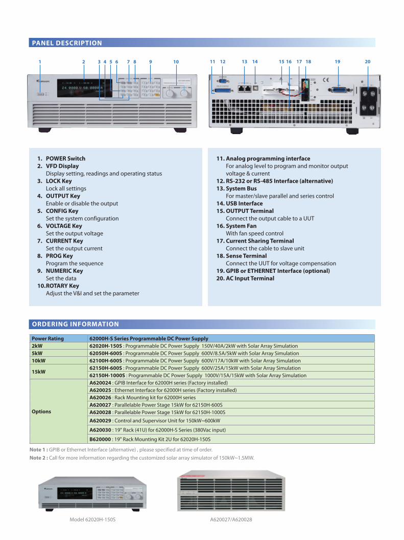
PANEL DESCRIPTION
ORDERING INFORMATION
Power Rating 62000H-S Series Programmable DC Power Supply2kW 62020H-150S : Programmable DC Power Supply 150V/40A/2kW with Solar Array Simulation5kW 62050H-600S : Programmable DC Power Supply 600V/8.5A/5kW with Solar Array Simulation10kW 62100H-600S : Programmable DC Power Supply 600V/17A/10kW with Solar Array Simulation
15kW62150H-600S : Programmable DC Power Supply 600V/25A/15kW with Solar Array Simulation62150H-1000S : Programmable DC Power Supply 1000V/15A/15kW with Solar Array Simulation
Options
A620024 : GPIB Interface for 62000H series (Factory installed)A620025 : Ethernet Interface for 62000H series (Factory installed)A620026 : Rack Mounting kit for 62000H seriesA620027 : Parallelable Power Stage 15kW for 62150H-600SA620028 : Parallelable Power Stage 15kW for 62150H-1000S
A620029 : Control and Supervisor Unit for 150kW~600kW
A620030 : 19" Rack (41U) for 62000H-S Series (380Vac input)
B620000 : 19" Rack Mounting Kit 2U for 62020H-150S
1 2 3 4 5 6 7 8 9 10 11 12 13 14 15 16 17 18 19 20
1. POWER Switch2. VFD Display Display setting, readings and operating status3. LOCK Key Lock all settings4. OUTPUT Key Enable or disable the output5. CONFIG Key Set the system configuration6. VOLTAGE Key Set the output voltage7. CURRENT Key Set the output current8. PROG Key Program the sequence9. NUMERIC Key Set the data10. ROTARY Key Adjust the V&I and set the parameter
11. Analog programming interface For analog level to program and monitor output voltage & current12. RS-232 or RS-485 Interface (alternative)13. System Bus For master/slave parallel and series control14. USB Interface15. OUTPUT Terminal Connect the output cable to a UUT16. System Fan With fan speed control17. Current Sharing Terminal Connect the cable to slave unit18. Sense Terminal Connect the UUT for voltage compensation19. GPIB or ETHERNET Interface (optional)20. AC Input Terminal
Note 1 : GPIB or Ethernet Interface (alternative) , please specified at time of order.Note 2 : Call for more information regarding the customized solar array simulator of 150kW~1.5MW.
Model 62020H-150S A620027/A620028

ELECTRICAL SPECIFICATIONS-WITH SOLAR ARRAY SIMULATION
MODEL 62020H-150S 62050H-600S 62100H-600S 62150H-600S 62150H-1000S Output RatingsOutput Voltage 0-150V 0-600V 0-600V 0-600V 0-1000VOutput Current 0-40A 0-8.5A 0-17A 0-25A 0-15AOutput Power 2000W 5000W 10000W 15000W 15000WLine RegulationVoltage +/- 0.01% F.S.Current +/- 0.05% F.S.Load RegulationVoltage +/- 0.05% F.S.Current +/- 0.1% F.S.Voltage MeasurementRange 60V / 150V 120V / 600V 120V / 600V 120V / 600V 200V / 1000VAccuracy 0.05% + 0.05%F.S.Current MeasurementRange 16A / 40A 3.4A / 8.5A 6.8A / 17A 10A / 25A 6A / 15AAccuracy 0.1% + 0.1%F.S.Output Noise&RippleVoltage Noise(P-P) 450 mV 1500 mV 1500 mV 1500 mV 2550 mVVoltage Ripple(rms) 65 mV 650 mV 650 mV 650 mV 1950 mVCurrent Ripple(rms) 80 mA 150 mA 300 mA 450 mA 270mAOVP Adjustment RangeRange 0-110% programmable from front panel, remote digital inputs. Accuracy +/- 1% of full-scale output Programming Response Time Rise Time: 50%F.S. CC Load 10ms (6.66A loading) 30ms 30ms 30ms 25msRise Time: No Load 10ms 30ms 30ms 30ms 25msFall Time: 50%F.S. CC Load 10ms (6.66A loading) 30ms 30ms 30ms 25msFall Time: 10%F.S. CC Load 83ms (1.33A loading) 100ms 100ms 100ms 80msFall Time: No Load 300ms 1.2s 1.2s 1.2s 3s Slew Rate Control Voltage Slew Rate Range 0.001V/ms - 15V/ms 0.001V/ms - 20V/ms 0.001V/ms - 20V/ms 0.001V/ms - 20V/ms 0.001V/ms - 40V/ms
Current Slew Rate Range0.001A/ms - 1A/ms,
or INF0.001A/ms - 0.1A/ms,
or INF0.001A/ms - 0.1A/ms,
or INF0.001A/ms - 0.1A/ms,
or INF0.001A/ms - 0.1A/ms,
or INFMinimum Transition Time 0.5msTransient response time Recovers within 1ms to +/- 0.75% of steady-state output for a 50% to 100% or 100% to 50% load change(1A/us)E�ciency 0.77(Typical) 0.87(Typical)Programming & Measurement ResolutionVoltage (Front Panel) 10 mV 10 mV 10 mV 10 mV 100mVCurrent (Front Panel) 1mA 1mA 1mA 1mA 1mAVoltage (Digital Interface) 0.002% of VmaxCurrent (Digital Interface) 0.002% of ImaxVoltage (Analog Interface) 0.04% of VmaxCurrent (Analog Interface) 0.04% of ImaxProgramming AccuracyVoltage (Front Panel and Digital Interface)
0.1% of Vmax
Current (Front Panel and Digital Interface)
0.3% of Imax
Voltage (Analog Interface) 0.2% of VmaxCurrent (Analog Interface) 0.3% of ImaxParallel Operation*2 Master / Slave control via CAN for 10 units up to 150kW. *1 (Parallel: ten units )Auto Sequencing (I-V program)Number of program 10Number of sequence 100Dwell time Range 1s - 15,000STrig. Source Manual / Auto
All specifications are subject to change without notice. Please visit our website for the most up to date specifications.Note*1 : Max. Power is 20kW for 62020H-150S.Note*2 : There is parallel mode for DC power supply when the I-V curve function is enabled.

GENERAL SPECIFICATIONS
All speci�cations are subject to change without notice. Please visit our website for the most up to date speci�cations.Note * : None APG interface for A620027/A620028
MODEL 62020H-150S 62050H-600S 62100H-600S 62150H-600S 62150H-1000SRemote InterfaceAnalog programming StandardUSB StandardRS232 StandardRS485 StandardGPIB OptionalEthernet OptionalSystem bus(CAN) Standard for master/slave controlGPIB Command Response TimeVout setting GPIB send command to DC source receiver <20msMeasure V&I Under GPIB command using Measure <25msAnalog Interface (I/O) *Voltage and Current Programming Inputs (I/P) 0-10Vdc / 0-5Vdc / 0-5k ohm / 4-20 mA of F.S.Voltage and Current monitor output (O/P) 0-10Vdc / 0-5Vdc / 4-20mA of F.S.External ON/OFF (I/P) TTL:Active Low or High(Selective)DC_ON Signal (O/P) Level by user de�ne. ( Time delay = 1 ms at voltage slew rate of 10V/ms.)CV or CC mode Indicator (O/P) TTL Level High=CV mode ; TTL Level Low= CC modeOTP Indicator (O/P) TTL: Active LowSystem Fault indicator(O/P) TTL: Active LowAuxiliary power supply(O/P) Nominal supply voltage : 12Vdc / Maximum current sink capability: 10mASafety interlock(I/P) Time accuracy: <100msRemote inhibit(I/P) TTL: Active LowAuto Sequencing(List Mode)Number of program 10Number of sequence 100Dwell time Range 5ms - 15000STrig. Source Manual / Auto / ExternalAuto Sequencing (Step Mode)Start voltage 0 to Full scaleEnd voltage 0 to Full scaleRun time 10ms - 99hoursInput Specification
AC Input Volatage 3Phase, 3Wire+Ground1Ø 200~220Vac ± 10% VLN
3Ø 200~220Vac ± 10% VLL
3Ø 380~400Vac ± 10% VLL
AC Frequency range 47 ~ 63Hz
Max Current (each phase)200/220Vac 15.2A 39A 69A 93A 93A380/400Vac -- 22A 37A 50A 50A
General Specification Maximum Remote Sense Line Drop Compensation
2% of full scale voltage per line (4% total)
Operating Temperature Range 00C ~ 400CStorage Temperature Range -400C ~ +850C
Dimension (HxWxD)89 x 428 x 465 mm/
3.5 x 16.85 x 16.73 inch132.8 mm x 428 mm x 610 mm / 5.23 x 16.85 x 24.02 inch
WeightApprox. 17 kg /
37.44 lbsApprox. 23 kg /
55.70 lbsApprox. 29 kg /
63.88 lbs Approx. 35 kg /
77.09 lbs Approx. 35 kg /
77.09 lbs Approval CE CE CE CE CE
62000H-S Series-E-201409-pdf
Worldwide Distribution and Service Network
JAPANCHROMA JAPAN CORP.472 Nippa-cho, Kouhoku-ku, Yokohama-shi, Kanagawa,223-0057 JapanTel: +81-45-542-1118Fax: +81-45-542-1080http://www.chroma.co.jpE-mail: [email protected]
U.S.A.CHROMA SYSTEMS SOLUTIONS, INC.19772 Pauling, Foothill Ranch, CA 92610 Tel: +1-949-600-6400Fax: +1-949-600-6401http://www.chromausa.comE-mail: [email protected]
Developed and Manufactured by :HEADQUARTERSCHROMA ATE INC.66 Hwaya 1st Rd., KueishanHwaya Technology Park,Taoyuan County 33383,TaiwanTel: +886-3-327-9999Fax: +886-3-327-8898http://www.chromaate.comE-mail: [email protected]
EUROPE CHROMA ATE EUROPE B.V.Morsestraat 32, 6716 AH Ede,The NetherlandsTel: +31-318-648282Fax: +31-318-648288http://www.chromaeu.comE-mail: [email protected]
CHINACHROMA ELECTRONICS (SHENZHEN) CO., LTD.8F, No.4, Nanyou Tian An Industrial Estate, Shenzhen, China PC: 518052Tel: +86-755-2664-4598Fax: +86-755-2641-9620