Embed Size (px)
Citation preview
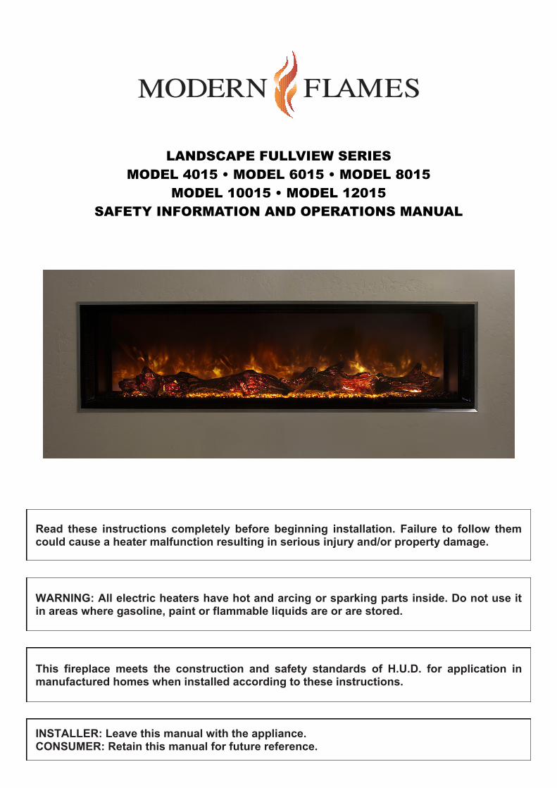
LANDSCAPE FULLVIEW SERIES
MODEL 4015 • MODEL 6015 • MODEL 8015
MODEL 10015 • MODEL 12015
SAFETY INFORMATION AND OPERATIONS MANUAL
Read these instructions completely before beginning installation. Failure to follow them could cause a heater malfunction resulting in serious injury and/or property damage.
WARNING: All electric heaters have hot and arcing or sparking parts inside. Do not use it in areas where gasoline, paint or flammable liquids are or are stored.
This fireplace meets the construction and safety standards of H.U.D. for application in manufactured homes when installed according to these instructions.
INSTALLER: Leave this manual with the appliance. CONSUMER: Retain this manual for future reference.
2
USER INSTRUCTIONS USER INSTRUCTIONS
TABLE OF CONTENTS
Important Instructions .................................. 2 Power Data .................................................. 3 Product Dimensions .................................... 4 Box Contents ............................................... 4 Unpacking and Testing ................................ 5 Locating Fireplace ....................................... 5 Installation ................................................... 6
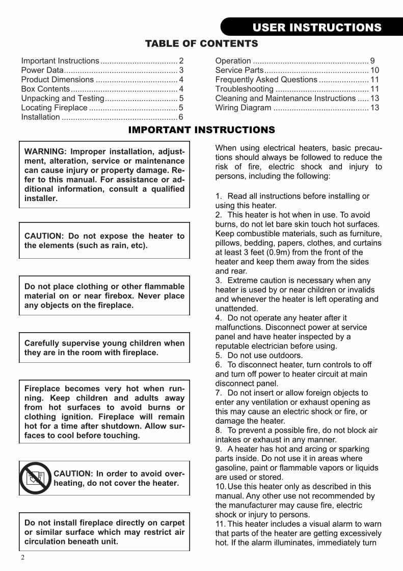
WARNING: Improper installation, adjust-ment, alteration, service or maintenance can cause injury or property damage. Re-fer to this manual. For assistance or ad-ditional information, consult a qualified installer.
CAUTION: Do not expose the heater to the elements (such as rain, etc).
Do not place clothing or other flammable material on or near firebox. Never place any objects on the fireplace.
Carefully supervise young children when they are in the room with fireplace.
Fireplace becomes very hot when run-ning. Keep children and adults away from hot surfaces to avoid burns or clothing ignition. Fireplace will remain hot for a time after shutdown. Allow sur-faces to cool before touching.
Do not install fireplace directly on carpet or similar surface which may restrict air circulation beneath unit.
Operation ................................................... 9 Service Parts .............................................. 10 Frequently Asked Questions ...................... 11 Troubleshooting ......................................... 11 Cleaning and Maintenance Instructions ..... 13 Wiring Diagram .......................................... 13
IMPORTANT INSTRUCTIONS
CAUTION: In order to avoid over-heating, do not cover the heater.
When using electrical heaters, basic precau-tions should always be followed to reduce the risk of fire, electric shock and injury to persons, including the following:
1. Read all instructions before installing or using this heater. 2. This heater is hot when in use. To avoid burns, do not let bare skin touch hot surfaces. Keep combustible materials, such as furniture, pillows, bedding, papers, clothes, and curtains at least 3 feet (0.9m) from the front of the heater and keep them away from the sides and rear. 3. Extreme caution is necessary when any heater is used by or near children or invalids and whenever the heater is left operating and unattended. 4. Do not operate any heater after it malfunctions. Disconnect power at service panel and have heater inspected by a reputable electrician before using. 5. Do not use outdoors. 6. To disconnect heater, turn controls to off and turn off power to heater circuit at main disconnect panel. 7. Do not insert or allow foreign objects to enter any ventilation or exhaust opening as this may cause an electric shock or fire, or damage the heater. 8. To prevent a possible fire, do not block air intakes or exhaust in any manner. 9. A heater has hot and arcing or sparking parts inside. Do not use it in areas where gasoline, paint or flammable vapors or liquids are used or stored. 10. Use this heater only as described in this manual. Any other use not recommended by the manufacturer may cause fire, electric shock or injury to persons. 11. This heater includes a visual alarm to warn that parts of the heater are getting excessively hot. If the alarm illuminates, immediately turn
3
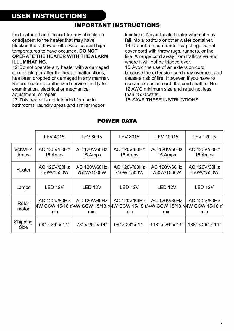
POWER DATA
LFV 4015 LFV 6015 LFV 8015 LFV 10015 LFV 12015
Volts/HZ Amps
AC 120V/60Hz 15 Amps
AC 120V/60Hz 15 Amps
AC 120V/60Hz 15 Amps
AC 120V/60Hz 15 Amps
AC 120V/60Hz 15 Amps
Heater AC 120V/60Hz 750W/1500W
AC 120V/60Hz 750W/1500W
AC 120V/60Hz 750W/1500W
AC 120V/60Hz 750W/1500W
AC 120V/60Hz 750W/1500W
Lamps LED 12V LED 12V LED 12V LED 12V LED 12V
Rotor motor
AC 120V/60Hz 4W CCW 15/18 r/
min
AC 120V/60Hz 4W CCW 15/18 r/
min
AC 120V/60Hz 4W CCW 15/18 r/
min
AC 120V/60Hz 4W CCW 15/18 r/
min
AC 120V/60Hz 4W CCW 15/18 r/
min
Shipping Size
58” x 26” x 14” 78” x 26” x 14” 98” x 26” x 14” 118” x 26” x 14” 138” x 26” x 14”
USER INSTRUCTIONS
the heater off and inspect for any objects on or adjacent to the heater that may have blocked the airflow or otherwise caused high temperatures to have occurred. DO NOT OPERATE THE HEATER WITH THE ALARM ILLUMINATING. 12. Do not operate any heater with a damaged cord or plug or after the heater malfunctions, has been dropped or damaged in any manner. Return heater to authorized service facility for examination, electrical or mechanical adjustment, or repair. 13. This heater is not intended for use in bathrooms, laundry areas and similar indoor
locations. Never locate heater where it may fall into a bathtub or other water container. 14. Do not run cord under carpeting. Do not cover cord with throw rugs, runners, or the like. Arrange cord away from traffic area and where it will not be tripped over. 15. Avoid the use of an extension cord because the extension cord may overheat and cause a risk of fire. However, if you have to use an extension cord, the cord shall be No. 12 AWG minimum size and rated not less than 1500 watts. 16. SAVE THESE INSTRUCTIONS
IMPORTANT INSTRUCTIONS
4
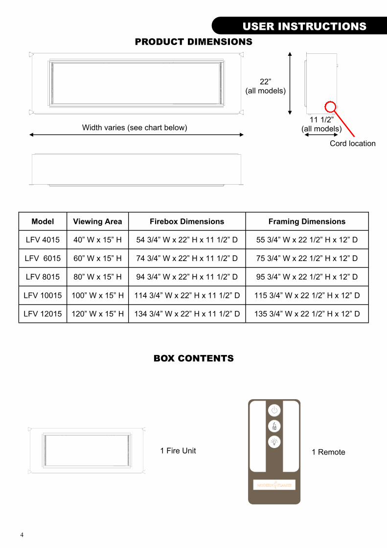
BOX CONTENTS
USER INSTRUCTIONS INSTALLATION
1 Fire Unit 1 Remote
PRODUCT DIMENSIONS
Width varies (see chart below) 11 1/2”
(all models)
22” (all models)
Model Viewing Area Firebox Dimensions Framing Dimensions
LFV 4015 40” W x 15” H 54 3/4” W x 22” H x 11 1/2” D 55 3/4” W x 22 1/2” H x 12” D
LFV 6015 60” W x 15” H 74 3/4” W x 22” H x 11 1/2” D 75 3/4” W x 22 1/2” H x 12” D
LFV 8015 80” W x 15” H 94 3/4” W x 22” H x 11 1/2” D 95 3/4” W x 22 1/2” H x 12” D
LFV 10015 100” W x 15” H 114 3/4” W x 22” H x 11 1/2” D 115 3/4” W x 22 1/2” H x 12” D
LFV 12015 120” W x 15” H 134 3/4” W x 22” H x 11 1/2” D 135 3/4” W x 22 1/2” H x 12” D
Cord location
5
INSTALLATION
UNPACKING AND TESTING
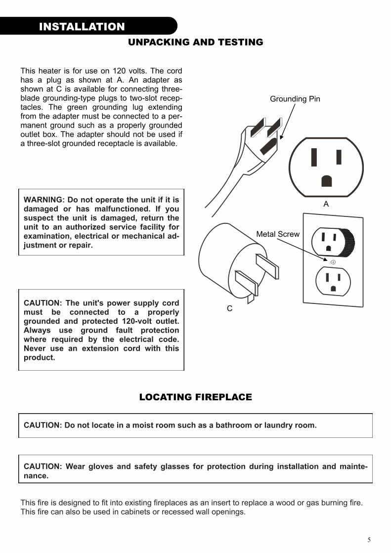
This heater is for use on 120 volts. The cord has a plug as shown at A. An adapter as shown at C is available for connecting three-blade grounding-type plugs to two-slot recep-tacles. The green grounding lug extending from the adapter must be connected to a per-manent ground such as a properly grounded outlet box. The adapter should not be used if a three-slot grounded receptacle is available.
CAUTION: The unit's power supply cord must be connected to a properly grounded and protected 120-volt outlet. Always use ground fault protection where required by the electrical code. Never use an extension cord with this product.
WARNING: Do not operate the unit if it is damaged or has malfunctioned. If you suspect the unit is damaged, return the unit to an authorized service facility for examination, electrical or mechanical ad-justment or repair.
LOCATING FIREPLACE
CAUTION: Do not locate in a moist room such as a bathroom or laundry room.
CAUTION: Wear gloves and safety glasses for protection during installation and mainte-
nance.
This fire is designed to fit into existing fireplaces as an insert to replace a wood or gas burning fire. This fire can also be used in cabinets or recessed wall openings.
A
C
Grounding Pin
Metal Screw
6
INSTALLATION INSTALLATION
INSTALLATION
WARNING - RISK OF FIRE! The power cord must not be pinched or against a sharp edge. Secure cord to avoid tripping or snagging to reduce the risk of fire, electric shock or personal in-
jury.
Do not run cord under carpeting. Do not cover cord with throw rugs, runners or the like. Arrange cord away from traffic areas and where it will not be tripped over.
WARNING - RISK OF FIRE! To prevent a possible fire, do not block air intake or exhaust in any manner. Do not use on soft surfaces where openings may become blocked.
WARNING - RISK OF FIRE! Do not blow or place insulation against the firebox.
Installing fireplace
Select a suitable location that is not suscep-tible to moisture and is a safe distance from drapes, furniture and high traffic areas. A qualified electrician should add a flexible 15 amp 120 volt circuit per local building codes. Note: Follow all national and local electrical codes.
WARNING: Avoid the use of an extension cord because the extension cord may overheat and cause a risk of fire. However, if you have to use an extension cord, the cord shall be No. 12 AWG minimum size and rated not less than 1500 watts.
WARNING: If the information in these in-structions is not followed exactly, a fire or explosion may result causing property damage, personal injury or death.
To reduce the risk of fire do not store or use gasoline or other flammable vapors in the vicinity of this or any other heater.
7
INSTALLATION
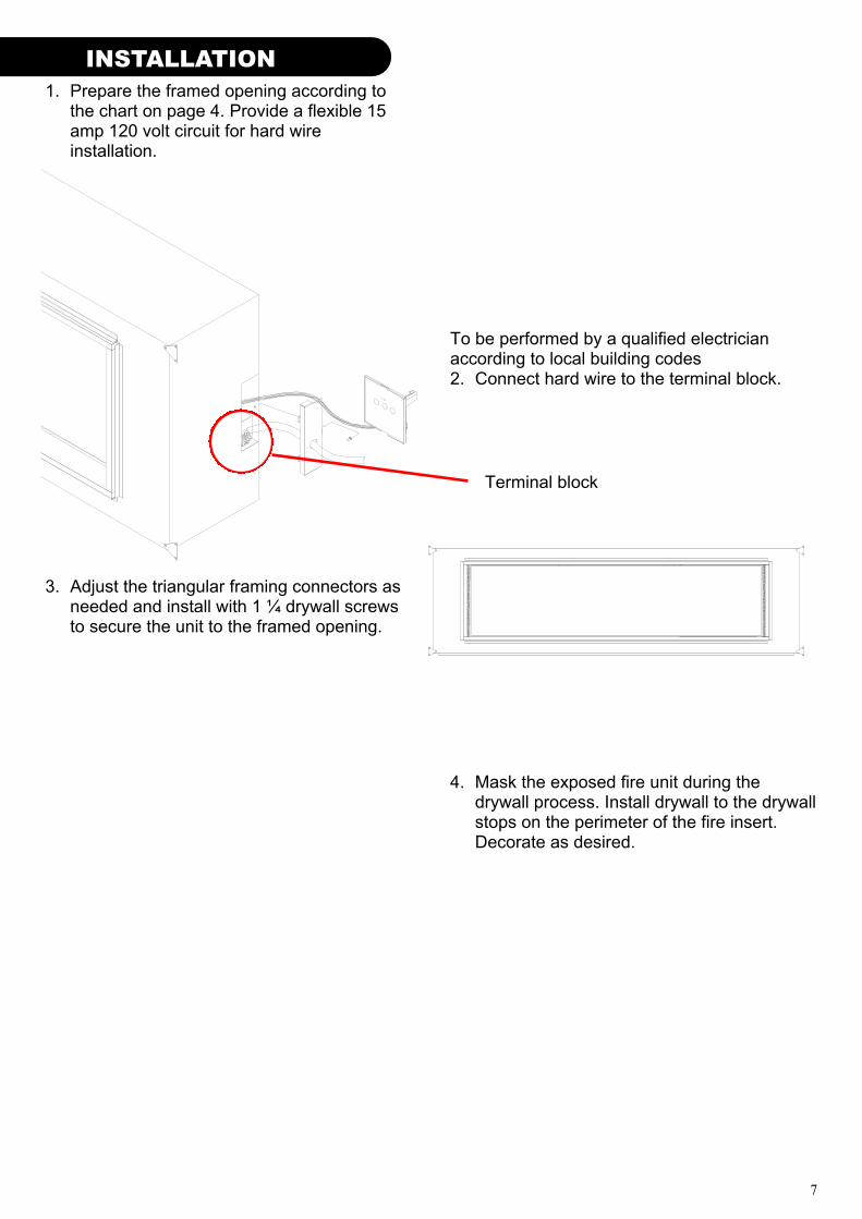
1. Prepare the framed opening according to the chart on page 4. Provide a flexible 15 amp 120 volt circuit for hard wire installation.
To be performed by a qualified electrician according to local building codes 2. Connect hard wire to the terminal block.
3. Adjust the triangular framing connectors as needed and install with 1 ¼ drywall screws to secure the unit to the framed opening.
4. Mask the exposed fire unit during the drywall process. Install drywall to the drywall stops on the perimeter of the fire insert. Decorate as desired.
Terminal block
8
INSTALLATION OPERATION
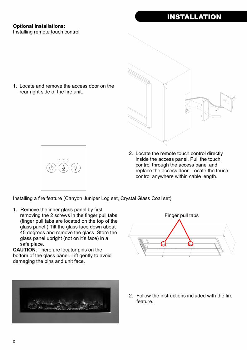
Finger pull tabs 1. Remove the inner glass panel by first
removing the 2 screws in the finger pull tabs (finger pull tabs are located on the top of the glass panel.) Tilt the glass face down about 45 degrees and remove the glass. Store the glass panel upright (not on it’s face) in a safe place.
CAUTION: There are locator pins on the bottom of the glass panel. Lift gently to avoid damaging the pins and unit face.
Installing a fire feature (Canyon Juniper Log set, Crystal Glass Coal set)
Optional installations: Installing remote touch control
2. Follow the instructions included with the fire feature.
1. Locate and remove the access door on the rear right side of the fire unit.
2. Locate the remote touch control directly inside the access panel. Pull the touch control through the access panel and replace the access door. Locate the touch control anywhere within cable length.
9
OPERATION
OPERATION
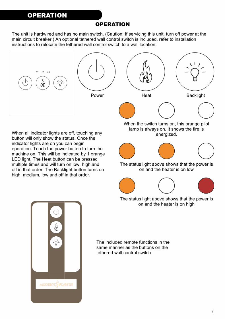
The unit is hardwired and has no main switch. (Caution: If servicing this unit, turn off power at the main circuit breaker.) An optional tethered wall control switch is included, refer to installation instructions to relocate the tethered wall control switch to a wall location.
When all indicator lights are off, touching any button will only show the status. Once the indicator lights are on you can begin operation. Touch the power button to turn the machine on. This will be indicated by 1 orange LED light. The Heat button can be pressed multiple times and will turn on low, high and off in that order. The Backlight button turns on high, medium, low and off in that order.
Power Heat Backlight
When the switch turns on, this orange pilot lamp is always on. It shows the fire is
energized.
The status light above shows that the power is on and the heater is on low
The status light above shows that the power is on and the heater is on high
The included remote functions in the same manner as the buttons on the tethered wall control switch
10
MAINTENANCE MAINTENANCE
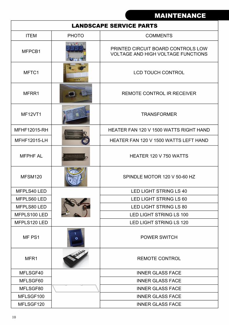
LANDSCAPE SERVICE PARTS
ITEM PHOTO COMMENTS
MFPCB1 PRINTED CIRCUIT BOARD CONTROLS LOW VOLTAGE AND HIGH VOLTAGE FUNCTIONS
MFTC1 LCD TOUCH CONTROL
MFRR1 REMOTE CONTROL IR RECEIVER
MF12VT1 TRANSFORMER
MFHF12015-RH
HEATER FAN 120 V 1500 WATTS RIGHT HAND
MFHF12015-LH HEATER FAN 120 V 1500 WATTS LEFT HAND
MFPHF AL HEATER 120 V 750 WATTS
MFSM120 SPINDLE MOTOR 120 V 50-60 HZ
MFPLS40 LED
LED LIGHT STRING LS 40
MFPLS60 LED LED LIGHT STRING LS 60
MFPLS80 LED LED LIGHT STRING LS 80
MFPLS100 LED LED LIGHT STRING LS 100
MFPLS120 LED LED LIGHT STRING LS 120
MF PS1 POWER SWITCH
MFR1 REMOTE CONTROL
MFLSGF40 INNER GLASS FACE
MFLSGF60 INNER GLASS FACE
MFLSGF80 INNER GLASS FACE
MFLSGF100 INNER GLASS FACE
MFLSGF120 INNER GLASS FACE
11
MAINTENANCE
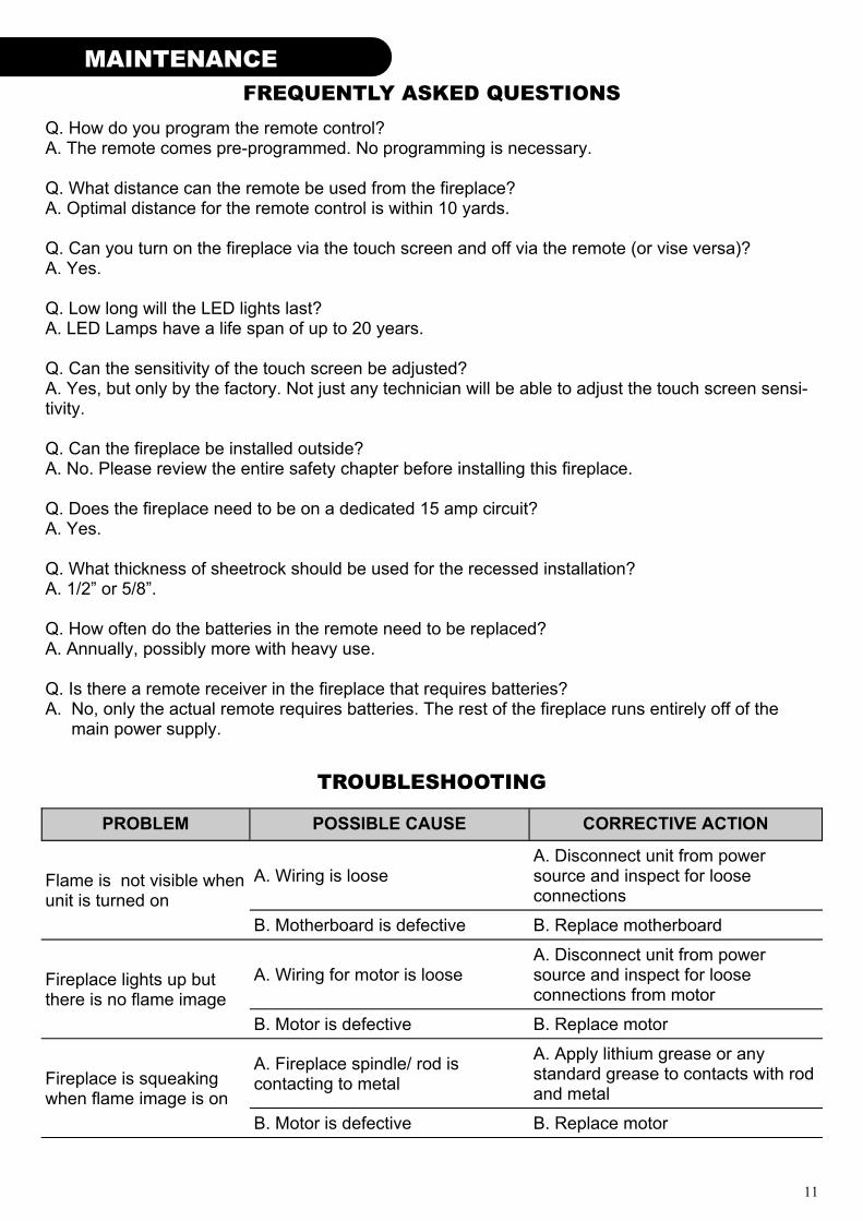
FREQUENTLY ASKED QUESTIONS
TROUBLESHOOTING
Q. How do you program the remote control? A. The remote comes pre-programmed. No programming is necessary. Q. What distance can the remote be used from the fireplace? A. Optimal distance for the remote control is within 10 yards. Q. Can you turn on the fireplace via the touch screen and off via the remote (or vise versa)? A. Yes. Q. Low long will the LED lights last? A. LED Lamps have a life span of up to 20 years. Q. Can the sensitivity of the touch screen be adjusted? A. Yes, but only by the factory. Not just any technician will be able to adjust the touch screen sensi-tivity. Q. Can the fireplace be installed outside? A. No. Please review the entire safety chapter before installing this fireplace. Q. Does the fireplace need to be on a dedicated 15 amp circuit? A. Yes. Q. What thickness of sheetrock should be used for the recessed installation? A. 1/2” or 5/8”. Q. How often do the batteries in the remote need to be replaced? A. Annually, possibly more with heavy use. Q. Is there a remote receiver in the fireplace that requires batteries? A. No, only the actual remote requires batteries. The rest of the fireplace runs entirely off of the
main power supply.
PROBLEM POSSIBLE CAUSE CORRECTIVE ACTION
Flame is not visible when unit is turned on
A. Wiring is loose A. Disconnect unit from power source and inspect for loose connections
B. Motherboard is defective B. Replace motherboard
Fireplace lights up but there is no flame image
A. Wiring for motor is loose A. Disconnect unit from power source and inspect for loose connections from motor
B. Motor is defective B. Replace motor
Fireplace is squeaking when flame image is on
A. Fireplace spindle/ rod is contacting to metal
A. Apply lithium grease or any standard grease to contacts with rod and metal
B. Motor is defective B. Replace motor
12
MAINTENANCE MAINTENANCE
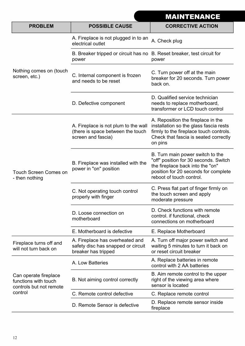
PROBLEM POSSIBLE CAUSE CORRECTIVE ACTION
Nothing comes on (touch screen, etc.)
A. Fireplace is not plugged in to an electrical outlet
A. Check plug
B. Breaker tripped or circuit has no power
B. Reset breaker, test circuit for power
C. Internal component is frozen and needs to be reset
C. Turn power off at the main breaker for 20 seconds. Turn power back on.
D. Defective component D. Qualified service technician needs to replace motherboard, transformer or LCD touch control
Touch Screen Comes on - then nothing
A. Fireplace is not plum to the wall (there is space between the touch screen and fascia)
A. Reposition the fireplace in the installation so the glass fascia rests firmly to the fireplace touch controls. Check that fascia is seated correctly on pins
B. Fireplace was installed with the power in "on" position
B. Turn main power switch to the "off" position for 30 seconds. Switch the fireplace back into the "on" position for 20 seconds for complete reboot of touch control.
C. Not operating touch control properly with finger
C. Press flat part of finger firmly on the touch screen and apply moderate pressure
D. Loose connection on motherboard
D. Check functions with remote control. if functional, check connections on motherboard
E. Motherboard is defective E. Replace Motherboard
Fireplace turns off and will not turn back on
A. Fireplace has overheated and safety disc has snapped or circuit breaker has tripped
A. Turn off major power switch and waiting 5 minutes to turn it back on or reset circuit breaker
Can operate fireplace functions with touch controls but not remote control
A. Low Batteries A. Replace batteries in remote control with 2 AA batteries
B. Not aiming control correctly B. Aim remote control to the upper right of the viewing area where sensor is located
C. Remote control defective C. Replace remote control
D. Remote Sensor is defective D. Replace remote sensor inside fireplace
13
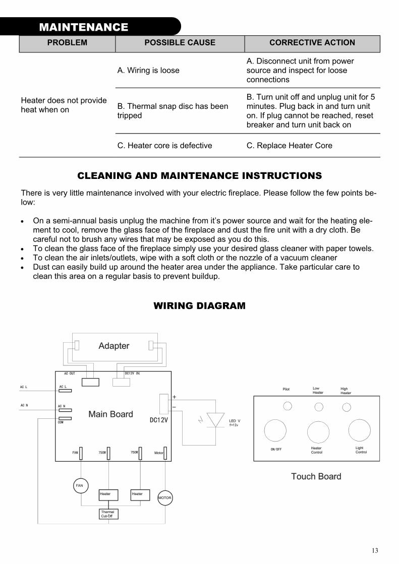
CLEANING AND MAINTENANCE INSTRUCTIONS
There is very little maintenance involved with your electric fireplace. Please follow the few points be-low: On a semi-annual basis unplug the machine from it’s power source and wait for the heating ele-
ment to cool, remove the glass face of the fireplace and dust the fire unit with a dry cloth. Be careful not to brush any wires that may be exposed as you do this.
To clean the glass face of the fireplace simply use your desired glass cleaner with paper towels. To clean the air inlets/outlets, wipe with a soft cloth or the nozzle of a vacuum cleaner Dust can easily build up around the heater area under the appliance. Take particular care to
clean this area on a regular basis to prevent buildup.
WIRING DIAGRAM
PROBLEM POSSIBLE CAUSE CORRECTIVE ACTION
A. Wiring is loose A. Disconnect unit from power source and inspect for loose connections
Heater does not provide heat when on B. Thermal snap disc has been
tripped
B. Turn unit off and unplug unit for 5 minutes. Plug back in and turn unit on. If plug cannot be reached, reset breaker and turn unit back on
C. Heater core is defective C. Replace Heater Core
MAINTENANCE

14
NOTES
MAINTENANCE MAINTENANCE

15
NOTES
MAINTENANCE

16
© 2013 www.modernflames.com
Please dispose of properly.