Embed Size (px)
Citation preview

THIS MANUAL MUST ACCOMPANY THE EQUIPMENT AT ALL TIMES.
To find the latest revision of this publication, visit our website at:
www.mqpower.com
Revision #0 (03/02/18)
OPERATION MANUAL
WHISPERWATT™ SERIES
MODEL DCA40SSKU4F60Hz Generator
(KUBOTA V2403-CR-T DIESEL ENGINE)

PAGE 2 — DCA40SSKU4F 60 HZ GENERATOR • OPERATION MANUAL — REV. #0 (03/02/18)
PROPOSITION 65 WARNING
Diesel engine exhaust and some of

DCA40SSKU4F 60 HZ GENERATOR • OPERATION MANUAL — REV. #0 (03/02/18) — PAGE 3
If you believe that your vehicle has a defect that could cause a crash or could cause injury or death, you should immediately inform the National Highway Traffic Safety Administration (NHTSA) in addition to notifying Multiquip at 1-800-421-1244.
If NHTSA receives similar complaints, it may open an investigation, and if it finds that a safety defect exists in a group of vehicles, it may order a recall and remedy campaign. However, NHTSA cannot become involved in individual problems between you, your dealer, or Multiquip.
To contact NHTSA, you may either call the Vehicle Safety Hotline toll-free at 1-888-327-4236 (TTY: 1-800-424-9153), go to http://www.nhtsa.dot.gov; or write to:
AdministratorNHTSA1200 New Jersey Avenue S.E.Washington, DC 20590
You can also obtain information about motor vehicle safety from http://www.safecar.gov.
REPORTING SAFETY DEFECTS

PAGE 4 — DCA40SSKU4F 60 HZ GENERATOR • OPERATION MANUAL — REV. #0 (03/02/18)
TABLE OF CONTENTS
DCA40SSKU4F 60HZ GeneratorProposition 65 Warning ........................................... 2Reporting Safety Defects ......................................... 3Table Of Contents .................................................... 4Safety Labels ........................................................... 5Safety Information .............................................. 6-11Specifications ........................................................ 12Dimensions ............................................................ 13Installation ........................................................ 14-15General Information ............................................... 16Major Components ................................................ 17Engine Control Panel ........................................ 18-19Generator Control Panel ........................................ 20Output Terminal Panel Familiarization .............. 21-23Load Application .................................................... 24Generator Outputs ................................................. 25Generator Outputs/Gauge Reading ....................... 26Output Terminal Panel Connections ................. 27-28Inspection/Setup ............................................... 29-32Generator Start-Up Procedure (Manual) .......... 33-35Generator Start-Up Procedure (Auto) .................... 36Generator Shut-Down Procedures ........................ 37Maintenance ..................................................... 38-47Troubleshooting Diagnostics ................................. 48Troubleshooting (Generator) .................................. 49Generator Wiring Diagram ..................................... 50Engine Wiring Diagram .......................................... 51Battery Charger Wiring Diagram ........................... 52Engine Block Heater Wiring Diagram .................... 53
NOTICE
Specifications are subject to change without notice.

DCA40SSKU4F 60 HZ GENERATOR • OPERATION MANUAL — REV. #0 (03/02/18) — PAGE 5
SAFETY LABELS
SAFETY LABELS
Safety labels are attached to the generator as shown in Keep these safety labels clean at all times. When the safety labels become worn or damaged, contact your nearest dealer or the Multiquip Parts Dept.
NOTICE
For safety label part numbers, reference parts manual..
Figure 1. Safety Decals
M91010000
CAUTIONHOT PARTS can burn skin.
DO NOT touch until the machine has sufficientlycooled.
M90310000
WARNINGHOT COOLANT can causesevere burns.
Do not remove cap ifradiator is hot.
DANGERUsing a generator indoors CAN KILL YOU IN MINUTES.
120V
OFF
GAC-2.2HPOWERED by
Honda Engines
120V15A
GR PRISE DETERRE
AC CIRCUIT BREAKERINTERRUPTEUR DECOURANT PRINCIPAL
NEUTRAL BONDED TO FRAMENEUTRE MIS A LA MASSE ALA CARCASSE DU MOTEUR
211052
120V
OFF
GAC-2.2HPOWERED by
Honda Engines
120V15A
GR PRISE DETERRE
AC CIRCUIT BREAKERINTERRUPTEUR DECOURANT PRINCIPAL
NEUTRAL BONDED TO FRAMENEUTRE MIS A LA MASSE ALA CARCASSE DU MOTEUR
211052
120V
OFF
GAC-2.2HPOWERED by
Honda Engines
120V15A
GR PRISE DETERRE
AC CIRCUIT BREAKERINTERRUPTEUR DECOURANT PRINCIPAL
NEUTRAL BONDED TO FRAMENEUTRE MIS A LA MASSE ALA CARCASSE DU MOTEUR
211052
NEVER use inside a homeor garage. Even if doorsand windows are open.
ONLY use OUTSIDE andfar away from windows,doors, and vents.
Generator exhaust contains carbon monoxide. This isa poison gas you cannot see or smell.
Avoid other generator hazards.READ MANUAL BEFORE USE.
M90320010
This machine stops and starts automaticallyand without notice.
CAUTIONM92010060
M9503000004
WARNINGMOVING PARTS can causesevere injury.
DO NOT operate with doorsopen.
Stop engine before servicing.
M9503200004
WARNINGENGINE EXHAUST can causesevere injury or death.
Use only in open, well ventilated areas orvent exhaust outside.
TOP VIEW
FAN SHROUD
CAUTIONMaximum capacity of lifting
bail is 5,150 lbs.M15000150
SIDE VIEW
4040
M92010000
WARNINGELECTRIC SHOCK HAZARD
Do not touch internal wiringor connections while this machine is operating.
Turn power off beforeservicing.
This machine stops and starts automaticallyand without notice.
CAUTIONM92010060
CAUTIONDO NOT disconnect the Battery Cables
after shutting down the engine forat least 30 seconds
M90130000
FRONT VIEW
M91020000
M92010070
WARNINGARC FLASH AND SHOCK HAZARDAppropriate PPE Required
Appropriate Personal ProtectionEquipment and Tools Requiredwhen working on this equipment.
DECREASEINCREASE
V-W
U-V
OFF
W-U
Low Oil Pressre
High temp.
Over Crank
Over Speed
Engine Started
ECU Intergrated Gauge Control
R
WARNINGELECTRIC SHOCK HAZARD
Do not touch outputterminals while this machine is operating.
Turn power off beforeservicing.
WARNINGELECTRIC SHOCK HAZARD
Always complete the groundingpath from the ground terminalon the genset to an externalgrounding source.
WARNINGBefore connecting this generator to any building’selectrical system, a licensed electrician must installan isolation (transfer) switch.
M92010050
Serious injury or death may result without thistransfer switch.
See instruction manual fordetails.
This unit is designed to contain operating fluids only. Theenvironmental containment is not designed to control fluidsfrom an external source. It is the operator’s responsibilityto monitor fluid levels at all times.
DO NOT EXCEED THE RECOMMENDEDMAXIMUM CAPACITY
M91010030
ENVIRONMENTAL WARNING
HIGH VOLTAGEDANGER
M92010040
CAUTIONStop engine beforeswitching.
M90130000
CONTROL BOX(Right-Side)
Operation of this equipment may createsparks that can start fires around dryvegetation.
A spark arrestor may be required.The operator should contact local fireagencies for laws or regulationsrelating to fire prevention requirements.
M9504200004
SIDE VIEW

PAGE 6 — DCA40SSKU4F 60 HZ GENERATOR • OPERATION MANUAL — REV. #0 (03/02/18)
SAFETY INFORMATION
DO NOT operate or service the generator before reading the entire manual. Safety precautions should be followed at all times when operating this generator. Failure to read and understand the safety messages and operating instructions could result in injury to yourself and others.
SAFETY MESSAGES
The four safety messages shown below will inform you about potential hazards that could injure you or others. The safety messages specifi cally address the level of exposure to the operator and are preceded by one of four words: DANGER, WARNING, CAUTION or NOTICE.
SAFETY SYMBOLS
DANGER
Indicates a hazardous situation which, if not avoided, WILL result in DEATH or SERIOUS INJURY.
WARNING
Indicates a hazardous situation which, if not avoided, COULD result in DEATH or SERIOUS INJURY.
CAUTION
Indicates a hazardous situation which, if not avoided, COULD result in MINOR or MODERATE INJURY.
NOTICE
Addresses practices not related to personal injury.
Potential hazards associated with the operation of this generator will be referenced with hazard symbols which may appear throughout this manual in conjunction with safety messages.

DCA40SSKU4F 60 HZ GENERATOR • OPERATION MANUAL — REV. #0 (03/02/18) — PAGE 7
SAFETY INFORMATION
GENERAL SAFETY
CAUTION
�NEVER operate this generator without proper protective clothing, shatterproof glasses, respiratory protection, hearing protection, steel-toed boots and other protective devices required by the job or city and state regulations.
�NEVER operate this generator when not feeling well due to fatigue, illness or when under medication.
�NEVER operate this generator under the infl uence of drugs or alcohol.
�ALWAYS check the generator for loosened threads or bolts before starting.
�DO NOT use the generator for any purpose other than its intended purposes or applications.
NOTICE
� This generator should only be operated by trained and qualifi ed personnel 18 years of age and older.
�Whenever necessary, replace nameplate, operation and safety decals when they become diffi cult read.
�Manufacturer does not assume responsibility for any accident due to generator modifi cations. Unauthorized generator modifi cation will void all warranties.
�NEVER use accessories or attachments that are not recommended by MQ Power for this generator. Damage to the generator and/or injury to user may result.
�ALWAYS know the location of the nearest fi re extinguisher.
�ALWAYS know the location of the nearest fi rst aid kit.
�ALWAYS know the location of the nearest phone or keep a phone on the job site. Also, know the phone numbers of the nearest ambulance, doctor and fi re department. This information will be invaluable in the case of an emergency.
GENERATOR SAFETY
DANGER
�NEVER operate the generator in an explosive atmosphere or near combustible materials. An explosion or fi re could result causing severe bodily harm or even death.
WARNING
�NEVER disconnect any emergency or safety devices. These devices are intended for operator safety. Disconnection of these devices can cause severe injury, bodily harm or even death. Disconnection of any of these devices will void all warranties.
CAUTION
�NEVER lubricate components or attempt service on a running machine.
NOTICE
�ALWAYS ensure generator is on level ground before use.
�ALWAYS keep the generator in proper running condition.
� Fix damage to generator and replace any broken parts immediately.
�ALWAYS store generator properly when it is not being used. Generator should be stored in a clean, dry location out of the reach of children and unauthorized personnel.

PAGE 8 — DCA40SSKU4F 60 HZ GENERATOR • OPERATION MANUAL — REV. #0 (03/02/18)
SAFETY INFORMATION
ENGINE SAFETY
DANGER
� The engine fuel exhaust gases contain poisonous carbon monoxide. This gas is colorless and odorless, and can cause death if inhaled.
� The engine in this generator requires an adequate free fl ow of cooling air. NEVER operate this generator in any enclosed or narrow area where free fl ow of the air is restricted. If the air fl ow is restricted it will cause injury to people and property and serious damage to the generator or engine.
WARNING
�DO NOT place hands or fingers inside engine compartment when engine is running.
�NEVER operate the engine with heat shields or guards removed.
�Keep fi ngers, hands hair and clothing away from all moving parts to prevent injury.
�DO NOT remove the radiator cap while the engine is hot. High pressure boiling water will gush out of the radiator and severely scald any persons in the general area of the generator.
�DO NOT remove the coolant drain plug while the engine is hot. Hot coolant will gush out of the coolant tank and severely scald any persons in the general area of the generator.
�DO NOT remove the engine oil drain plug while the engine is hot. Hot oil will gush out of the oil tank and severely scald any persons in the general area of the generator.
CAUTION
�NEVER touch the hot exhaust manifold, muffl er or cylinder. Allow these parts to cool before servicing generator.
NOTICE
�NEVER run engine without an air fi lter or with a dirty air fi lter. Severe engine damage may occur. Service air fi lter frequently to prevent engine malfunction.
�NEVER tamper with the factory settings of the engine or engine governor. Damage to the engine or generator can result if operating in speed ranges above the maximum allowable.
�Wet stacking is a common problem with diesel engines which are operated for extended periods with light or no load applied. When a diesel engine operates without suffi cient load (less than 40% of the rated output), it will not operate at its optimum temperature. This will allow unburned fuel to accumulate in the exhaust system, which can foul the fuel injectors, engine valves and exhaust system, including turbochargers, and reduce the operating performance.
In order for a diesel engine to operate at peak effi ciency, it must be able to provide fuel and air in the proper ratio and at a high enough engine temperature for the engine to completely burn all of the fuel.
Wet stacking does not usually cause any permanent damage and can be alleviated if additional load is applied to relieve the condition. It can reduce the system performance and increase maintenance. Applying an increasing load over a period of time until the excess fuel is burned off and the system capacity is reached usually can repair the condition. This can take several hours to burn off the accumulated unburned fuel.
�State Health Safety Codes and Public Resources Codes specify that in certain locations, spark arresters must be used on internal combustion engines that use hydrocarbon fuels. A spark arrester is a device designed to prevent accidental discharge of sparks or fl ames from the engine exhaust. Spark arresters are qualifi ed and rated by the United States Forest Service for this purpose. In order to comply with local laws regarding spark arresters, consult the engine distributor or the local Health and Safety Administrator.

DCA40SSKU4F 60 HZ GENERATOR • OPERATION MANUAL — REV. #0 (03/02/18) — PAGE 9
SAFETY INFORMATION
FUEL SAFETY
DANGER
�DO NOT start the engine near spilled fuel or combustible fl uids. Diesel fuel is extremely fl ammable and its vapors can cause an explosion if ignited.
�ALWAYS refuel in a well-ventilated area, away from sparks and open fl ames.
�ALWAYS use extreme caution when working with fl ammable liquids.
�DO NOT fi ll the fuel tank while the engine is running or hot.
�DO NOT overfi ll tank, since spilled fuel could ignite if it comes into contact with hot engine parts or sparks from the ignition system.
�Store fuel in appropriate containers, in well-ventilated areas and away from sparks and fl ames.
�NEVER use fuel as a cleaning agent.
�DO NOT smoke around or near the generator. Fire or explosion could result from fuel vapors or if fuel is spilled on a hot engine.
ELECTRICAL SAFETY
DANGER
�DO NOT touch output terminals during operation. Contact with output terminals during operation can cause electrocution, electrical shock or burn.
� The electrical voltage required to operate the generator can cause severe injury or even death through physical contact with live circuits. Turn generator and all circuit breakers OFF before performing maintenance on the generator or making contact with output terminals.
�NEVER insert any objects into the output receptacles during operation. This is extremely dangerous. The possibility exists of electrical shock, electrocution or death.
�Backfeed to a utility system can cause electrocution and/or property damage. NEVER connect the generator to a building’s electrical system without a transfer switch or other approved device. All installations should be performed by a licensed electrician in accordance with all applicable laws and electrical codes. Failure to do so could result in electrical shock or burn, causing serious injury or even death.
Power Cord/Cable Safety
DANGER
�NEVER let power cords or cables lay in water.
�NEVER stand in water while AC power from the generator is being transferred to a load.
�NEVER use damaged or worn cables or cords when connecting generator to generator. Inspect for cuts in the insulation.
�NEVER grab or touch a live power cord or cable with wet hands. The possibility exists of electrical shock, electrocution or death.
�Make sure power cables are securely connected to the generator’s output receptacles. Incorrect connections may cause electrical shock and damage to the generator.
NOTICE
�ALWAYS make certain that proper power or extension cord has been selected for the job. See Cable Selection Chart in this manual.

PAGE 10 — DCA40SSKU4F 60 HZ GENERATOR • OPERATION MANUAL — REV. #0 (03/02/18)
SAFETY INFORMATION
Grounding Safety
DANGER
� This generator is equipped with a grounding terminal attached to the enclosure. Electrical grounding requirements can differ by State, Province, District, Municipality, and unique application settings.
� For portable and vehicle-mounted generators, Multiquip recognizes the guidance provided in NEC Handbook Article 250.34 Parts A and B, and 29 CFR 1926.404 (f) (3) (i). If a more defi nitive earth-to-ground safeguard is required, please consult a qualifi ed electrician and reference appropriate National Electrical Code (NEC) guidelines in establishing an exterior grounding point generator.
�NEVER use gas piping as an electrical ground.
NOTICE
� There is a permanent conductor bond between generator (stator winding) and the frame.
BATTERY SAFETY
DANGER
�DO NOT drop the battery. There is a possibility that the battery will explode.
�DO NOT expose the battery to open fl ames, sparks, cigarettes, etc. The battery contains combustible gases and liquids. If these gases and liquids come into contact with a fl ame or spark, an explosion could occur.
WARNING
�ALWAYS wear safety glasses when handling the battery to avoid eye irritation. The battery contains acids that can cause injury to the eyes and skin.
�Use well-insulated gloves when picking up the battery.
�ALWAYS keep the battery charged. If the battery is not charged, combustible gas will build up.
�ALWAYS recharge the battery in a well-ventilated environment to avoid the risk of a dangerous concentration of combustible gasses.
� If the battery liquid (dilute sulfuric acid) comes into contact with clothing or skin, rinse skin or clothing immediately with plenty of water.
� If the battery liquid (dilute sulfuric acid) comes into contact with eyes, rinse eyes immediately with plenty of water and contact the nearest doctor or hospital to seek medical attention.
CAUTION
�ALWAYS disconnect the NEGATIVE battery terminal before performing service on the generator.
�ALWAYS keep battery cables in good working condition. Repair or replace all worn cables.

DCA40SSKU4F 60 HZ GENERATOR • OPERATION MANUAL — REV. #0 (03/02/18) — PAGE 11
SAFETY INFORMATION
ENVIRONMENTAL SAFETY/DECOMMISSIONING
NOTICE
Decommissioning is a controlled process used to safely retire a piece of generator that is no longer serviceable. If the generator poses an unacceptable and unrepairable safety risk due to wear or damage or is no longer cost effective to maintain (beyond life-cycle reliability) and is to be decommissioned (demolition and dismantlement),be sure to follow rules below.
�DO NOT pour waste or oil directly onto the ground, down a drain or into any water source.
�Contact your country's Department of Public Works or recycling agency in your area and arrange for proper disposal of any electrical components, waste or oil associated with this generator. �When the life cycle of this generator is over, remove battery(s) and bring to an appropriate facility for lead reclamation. Use safety precautions when handling batteries that contain sulfuric acid. �When the life cycle of this generator is over, it is recommended that the generator frame and all other metal parts be sent to a recycling center.Metal recycling involves the collection of metal from discarded products and its transformation into raw materials to use in manufacturing a new product.Recyclers and manufacturers alike promote the process of recycling metal. Using a metal recycling center promotes energy cost savings.
EMISSIONS INFORMATION
NOTICE
The diesel engine used in this generator has been designed to reduce harmful levels of carbon monoxide (CO), hydrocarbons (HC) and nitrogen oxides (NOx) contained in diesel exhaust emissions.
This engine has been certifi ed to meet US EPA Evaporative emissions requirements in the installed confi guration.
Attempting to modify or make adjustments to the engine emission system by unauthorized personnel without proper training could damage the generator or create an unsafe condition.
Additionally, modifying the fuel system may adversely affect evaporative emissions, resulting in fi nes or other penalties.
Emission Control Label
The emission control label is an integral part of the emission system and is strictly controlled by regulations.
The label must remain with the engine for its entire life.
If a replacement emission label is needed, please contact your authorized engine distributor.

PAGE 12 — DCA40SSKU4F 60 HZ GENERATOR • OPERATION MANUAL — REV. #0 (03/02/18)
SPECIFICATIONS
Table 1. Generator SpecificationsModel DCA-40SSKU4F
Type Revolving field, self ventilated, open protected type synchronous generator
Armature Connection Star with Neutral ZigzagPhase 3 Single
Standby Output 29.7 KW (37 kVA) 27.3 KWPrime Output 28.8 KW (36 kVA) 26 KW
3Ø Voltage (L-L/L-N) Voltage Selector Switch at 3Ø 240/139
208Y/120, 220Y/127, 240Y/139 N/A
3Ø Voltage (L-L/L-N) Voltage Selector Switch at 3Ø 480/277
416Y/240, 440Y/254, 480Y/277 N/A
1Ø Voltage (L-L/L-N) Voltage Selector Switch at 1Ø 240/120 N/A 240/120
Power Factor 0.8 1.0Frequency 60 Hz
Speed 1800 rpmAux. AC Power Single Phase, 60 Hz
Aux. Voltage/Output 4.8 Kw (2.4 kW x 2) Dry Weight 2,250lbs. (1,020 kg)Wet Weight 2,823 lbs. (1,280 kg)
Table 2. Engine SpecificationsModel Kubota V2403-CR-T
Type 4-cycle, water cooled, direct injection, turbocharged, EGR, ECM, DOC and DPF
No. of Cylinders 4 cylindersBore x Stroke 3.42 x 4.01 in. (87 x 102 mm)Displacement 148.5 in3 (2.43 liters)Rated Output 48.3 HP at 1800 rpm
Starting Electric Coolant Capacity 2.77 gal. (10.5 liters)Lube Oil Capacity 3.4 gal. (12.8 liters)Engine Oil Type API service class CJ-4 or JASO DH-2
Fuel Type Ultra Low Sulfer No. 2 Diesel FuelFuel Tank Capacity 67.4 gal. (255 liters)
Fuel Consumption2.2 gal. (8.5 L)/hr at full load 1.7 gal. (6.4 L)/hr at 3/4 load1.2 gal. (4.4 L)/hr at 1/2 load 0.8 gal. (2.9 L)/hr at 1/4 load
Battery 27 (CCA 0° 800A) x 1

DCA40SSKU4F 60 HZ GENERATOR • OPERATION MANUAL — REV. #0 (03/02/18) — PAGE 13
DIMENSIONS
F
FRONT VIEW
I
G
A E
D
B
TOP VIEW
SIDE VIEW
C
40
M91020000
H
MAXIMUMLIFTING POINT
5,150 LBS. (2,315 KG)
Figure 2. Dimensions
Table 3. DimensionsReference
LetterDimension in. (mm) Reference Letter Dimension in. (mm)
A 24.88 (632) E 25.51 (648)
B 24.88 (632) F 76.38 (1,940)
C 25.51 (648) G 62.20 (1,580)
D 32.28 (820) H 37.40 (950)

PAGE 14 — DCA40SSKU4F 60 HZ GENERATOR • OPERATION MANUAL — REV. #0 (03/02/18)
INSTALLATION
GENERATORGROUND LUG
GROUND CABLE
REFERENCENEC 250-83 (C)
GROUND ROD FOR EARTH GROUND.CONNECT TO BUILDINGGROUND IF APPLICABLE
Figure 3. Typical Generator Grounding Application
CONNECTING THE GROUND
Consult with local Electrical and Safety Codes for proper connection based on condition of use.
EXAMPLE of how to ground the unit if the condition of use requires such a device:
The ground terminal on the generator should always be used to connect the generator to a suitable ground when required.
The ground cable should be #8 size wire (aluminum) minimum. If copper wire is used, #10 size wire minimum should be used.
Connect one end of the ground cable terminal to the generator ground point (Figure 3). Connect the other end of the ground cable to a suitable earth ground (ground rod).

DCA40SSKU4F 60 HZ GENERATOR • OPERATION MANUAL — REV. #0 (03/02/18) — PAGE 15
INSTALLATION
OUTDOOR INSTALLATION
Install the generator in a area that is free of debris, bystanders, and overhead obstructions. Make sure the generator is on secure level ground so that it cannot slide or shift around. Also install the generator in a manner so that the exhaust will not be discharged in the direction of nearby homes.
The installation site must be relatively free from moisture and dust. All electrical equipment should be protected from excessive moisture. Failure to do so will result in deterioration of the insulation and will result in short circuits and grounding.
Foreign materials such as dust, sand, lint and abrasive materials have a tendency to cause excessive wear to engine and alternator parts.
INDOOR INSTALLATION
Exhaust gases from diesel engines are extremely poisonous. Whenever an engine is installed indoors the exhaust fumes must be vented to the outside. The engine should be installed at least two feet from any outside wall. Using an exhaust pipe which is too long or too small can cause excessive back pressure which will cause the engine to heat excessively and possibly burn the valves.
MOUNTING
The generator must be mounted on a solid foundation (such as concrete) and set firmly on the foundation to isolate vibration of the generator when it is running. The generator must set at least 6 inches above the floor or grade level (in accordance to NFPA 110, Chapter 54.1). DO NOT remove the metal skids on the bottom of the generator. They are there to resist damage to the bottom of the generator and to maintain alignment.
CAUTION
Pay close attention to ventilation when operating the generator inside tunnels and caves. The engine exhaust contains noxious elements. Engine exhaust must be routed to a ventilated area.
GENERATOR GROUNDING
If applicable, to guard against electrical shock and possible damage to the equipment, it is important to provide a good EARTH ground, (Figure 3).
Article 250 (Grounding) of the NEC handbook provides guidelines for proper grounding and specifies that the cable ground shall be connected to the grounding system of the building as close to the point of cable entry as practical.
NEC article 250 specifices the following grounding requirements:
1. Use one of the following wire types to connect the generator to earth ground.
a. Copper 10 AWG (5.3 mm2) or larger.
b. Aluminum 8 AWG (8.4 mm2) or larger.
2. When grounding of the generator (Figure 3) is required, connect one end of the ground cable to the ground lug on the generator. Connect the other end of the ground cable to the ground rod (earth ground).
3. NEC article 250 specifies that the earth ground rod should be buried a minimum of 8 ft. into the ground.
NOTICE
The Occupational Safety and Health Administration (OSHA) and the National Electrical Code (NEC) recommend that if the generator is providing electrical power to a structure (home, office shop, trailer or similar) it must be connected to a grounding electrode system, such as a driven ground rod (Figure 3).
NOTICE
ALWAYS check with State, Province, District and Municipalities for electrical grounding requirements before using generator.
NOTICE
When connecting the generator to any building's electrical system, ALWAYS consult with a licensed electrician.

PAGE 16 — DCA40SSKU4F 60 HZ GENERATOR • OPERATION MANUAL — REV. #0 (03/02/18)
GENERATORThis MQ Power generator (Figure 4) is a high quality portable (requires a trailer for transport) power source for telecom sites, lighting facilities, power tools, submersible pumps and other industrial and construction machinery.
ENGINE CONTROL PANELThe “Engine Operating Panel” is provided with the following:
�Engine Warning Lamp Module• Engine Shutdown LED• Engine Pre-Alarm LED• Charging Battery LED• Pre-Heat LED• Fuel Filter Water Level LED• Fuel Leak Detected LED• High Exhaust System Temperature (HEST) LED• Manual Regeneration LED
� Fuel Gauge �Auto-Start Controller �Hour Meter �Speed Control Switch �Auto Start Switch �Diagnostic Switch �Emergency Stop Button (Optional)
GENERATOR CONTROL PANELThe “Generator Control Panel” is provided with the following:
� Frequency Meter (Hz) �AC Ammeter (Amps) �AC Voltmeter (Volts) �Ammeter Change-Over Switch �Voltage Regulator � 3-Pole, 110 amp Main Circuit Breaker � “Control Box” (Located Behind Eng/Gen Control Panel)• Automatic Voltage Regulator• Current Transformer• Over-Current Relay• Starter Relay• Voltage Selector Switch
OUTPUT TERMINAL PANELThe “Output Terminal Panel” is provided with the following:
� Two 250 VAC output receptacles (CS-6369), 50 amps � Two auxiliary circuit breakers, 250V @50 amps � Two 125 VAC output receptacles, (GFCI), 20 amps � Two duplex circuit breakers, 125V@ 20 amps � Five output terminal lugs (3Ø power)
OPTIONS �Battery Charger �Water Heater � Low Coolant Level Switch/Indicator �Camlock Connectors �Emergency Stop Switch
OPEN DELTA EXCITATION SYSTEMThis generator is equipped with the state of the art “Open-Delta” excitation system. The open delta system consists of an electrically independent winding wound among stationary windings of the AC output section.There are four connections of the open delta A, B, C and D. During steady state loads, the power from the voltage regulator is supplied from the parallel connections of A to B, A to D, and C to D. These three phases of the voltage input to the voltage regulator are then rectified and are the excitation current for the exciter section. When a heavy load, such as a motor starting or a short circuit occurs, the automatic voltage regulator (AVR) switches the configuration of the open delta to the series connection of B to C. This has the effect of adding the voltages of each phase to provide higher excitation to the exciter section and thus better voltage response during the application of heavy loads. The connections of the AVR to the AC output windings are for sensing only. No power is required from these windings.The open-delta design provides virtually unlimited excitation current, offering maximum motor starting capabilities. The excitation does not have a “fixed ceiling” and responds according to the demands of the required load.ENGINEThis generator unit incorporates a Kubota V2403-CR-T 4-cycle water cooled, direct injection turbocharged diesel engine. This engine is designed to meet every performance requirement for the generator. Reference Table 2 for engine specifications.
In keeping with MQ Power’s policy of constantly improving its products, the specifications quoted herein are subject to change without prior notice.ELECTRIC GOVERNOR SYSTEMThe electric governor system controls the RPMs of the engine. When the engine demand increases or decreases, the governor system regulates the frequency variation to ±.25%.
GENERAL INFORMATION

DCA40SSKU4F 60 HZ GENERATOR • OPERATION MANUAL — REV. #0 (03/02/18) — PAGE 17
MAJOR COMPONENTS
M91020000
DECREASEINCREASE
40
V-W
U-V
OFF
W-U
OFF/RESET
PRESSURE
HIGH COOLANT
ENGINE RUNNING
U V W O
3 PHASE240/139
1 PHASE240/120
3 PHASE480/277
PRESS TO LOCK
40
4
8 5
11
12 13
10
TOP VIEW
FRONT VIEW
SIDE VIEW
1
3
9
7 6
2
Low Oil Pressre
High temp.
Over Crank
Over Speed
Engine Started
ECU Intergrated Gauge Control
R
14
Figure 4. Major Components
Table 4. Generator Major ComponentsITEM NO. DESCRIPTION
1 Voltage Selector Switch Assembly2 Air Cleaner Assembly3 Muffler Assembly4 Fuel Tank Assembly5 Fuel Drain Plug6 Engine/Radiator Assembly7 Coolant Drain Plug8 Output Terminal Panel Assembly9 Generator Assembly
10 Lifting Hook11 Battery12 Engine Control Panel Assembly13 Generator Control Panel Assembly14 Load Bank

PAGE 18 — DCA40SSKU4F 60 HZ GENERATOR • OPERATION MANUAL — REV. #0 (03/02/18)
Figure 5. Engine Control Panel
DECREASEINCREASE
V-W
U-V
OFF
W-U
1 2
3
4
5
Low Oil Pressre
High temp.
Over Crank
Over Speed
Engine Started
ECU Intergrated Gauge Control
R
6
A
B
C
D
G
H
E
F
The definitions below and on the preceeding page describe the controls and functions of the Engine Control Panel (Figure 5).
1. Engine Warning LEDs — There are six engine warning lamps, they are defined as follows:
a. Engine Shutdown — Indicates that the engine has shutdown due to an engine failure. LED will turn on.
b. Engine Pre Alarm LED — Indicates that an engine failure has occured. LED will turn on or blink.
c. Battery Charge Alarm LED — This LED is ON when the output voltage of the alternator drops below a set value. If this lamp is ON during normal operation, the emergency shutdown system will immediately stop the engine.
d. Fuel Filter Water Level LED — This LED is ON when the water level in the fuel filter is extraordinarily high.
e. Fuel Leak Detected Lamp LED — This LED is ON when the fluid in the containment is higher than the allowable level.
f. Pre-Heat LED — The pre-heat LED will be ON during the pre-heating cycle (cold weather conditions). When the pre-heat cycle is completed the LED will turn OFF and the engine can be started.
g. HEST LED — Hight Exhaust System Temperature LED turns ON during the regeneration process. When in this mode, the DPF exhaust temperature is very high.
h. Manual Regeneration Request LED — This LED turns ON to notify that the DPF regeneration is required to reduce the increased soot levels.
i. Regeneration Start Pushbutton — Press this button to manually start the regeneration process.
NOTICE
The area above and around the generator during the regeneration process should be free of any type of debris, flammable or conbustible materials, as temperatures during the regeneration process can reach as high as 1,022 °F (550 °C).
ENGINE CONTROL PANEL

DCA40SSKU4F 60 HZ GENERATOR • OPERATION MANUAL — REV. #0 (03/02/18) — PAGE 19
ENGINE CONTROL PANEL
2. Auto START/STOP Engine Controller (CAN 78) — This controller has a vertical row of status LED's (inset), that when lit, indicate that an engine malfunction (fault) has been detected. When a fault has been detected, the engine controller will evaluate the fault and all major faults will shutdown the generator. During the cranking cycle, the ECU will attempt to crank the engine for 10 seconds before disengaging.
If the engine does not engage (start) by the third attempt, the engine will be shutdown by the engine controller’s Over Crank Protection mode. If the engine engages at a speed (RPM's) that is not safe, the controller will shutdown the engine by initializing the Over Speed Protection mode.
Also, the engine controller will shut down the engine in the event of low oil pressure, high coolant temperature, low coolant level, and loss of magnetic pickup. These conditions can be observed by monitoring the LED status indicators on the front of the controller module.
A. Low Oil Pressure — Indicates the engine pressure has fallen below 14.2 psi (98 kPa). The oil pressure is detected using variable resistive values from the oil pressure sending unit. This is considered a major fault and the engine will be shut down.
B. High Coolant Temperature — Indicates the engine temperature has exceeded 212° F (100° C). The engine temperature is detected using variable resistive values from the temperature sending unit. This is considered a major fault and the engine will be shut down.
C. Overcrank Shutdown — Indicates the unit has attempted to start a pre-programmed number of times, and has failed to start. The number of cycles and duration are programmable. It is pre-set at three cycles with a 10 second duration. This is considered a major fault.
D. Overspeed Shutdown — Indicates the engine is running at an unsafe speed. This is considered a major fault.
E. Engine Running — Indicates that engine is running at a safe operating speed.
3. Fuel Guage — Indicates amount of diesel fuel available.
4. Hour Meter — Indicates amount of time generator has been in use.
5. Auto Start Stop Switch — This switch controls the running of the unit. If this switch is set to the OFF/RESET position, the unit will not run. When this switch is set to the manual position, the generator will start immediately.
If the generator is to be connected to a building’s AC power source via an automatic transfer switch (isolation), place the switch in the AUTO position. In this position, should an outage occur, the automatic transfer switch (ATS) will start the generator automatically via the generator’s auto-start contacts connected to the ATS’s start contacts. Please refer to your ATS installation manual for further instructions for the correct installation of the auto-start contacts of the generator to the ATS.
6. Diagnostic Switch — When activated, fault errors in the engine or the engine control system will be displayed on the engine warning module (LED's).

PAGE 20 — DCA40SSKU4F 60 HZ GENERATOR • OPERATION MANUAL — REV. #0 (03/02/18)
GENERATOR CONTROL PANEL
Figure 6. Generator Control Panel
DECREASEINCREASE
V-W
U-V
OFF
W-U
4
Low Oil Pressure
High temp.
Over Crank
Over Speed
Engine Started
ECU Intergrated Gauge Control
1
2
3
4
R
6
7
8
A
B
C
D
G
H
E
F
The definitions below describe the controls and functions of the Generator Control Panel (Figure 6).
1. Frequency Meter — Indicates the output frequency in hertz (Hz). Normally 60 Hz.
2. AC Ammeter — Indicates the amount of current the load is drawing from the generator per leg selected by the ammeter phase-selector switch.
3. AC Voltmeter — Indicates the output voltage present at the U,V, and W output terminal lugs.
4. Engine Speed Switch — This switch controls the speed of the engine (low/high).
5. Ammeter Change-Over Switch — This switch allows the AC ammeter to indicate the current flowing to the load connected to any phase of the output terminals or to be switched off. This switch does not effect the generator output in any fashion, it is for current reading only.
6. Voltage Regulator Control — Allows ±15% manual adjustment of the generator’s output voltage.
7. Emergency Stop Button (Option) — Push this button inward to stop the engine in the event of an emergency. DO NOT use this button as a means of stopping the engine.
8. Main Circuit Breaker — This three-pole, 110A main breaker is provided to protect the the U,V, and W Output Terminal Lugs from overload.
NOTICE
Remember the overcurrent relay monitors the current flowing from the U,V, and W output terminal lugs to the load.
In the event of a short circuit or over current condition, it will automatically trip the 110 amp main breaker.
To restore power to the output terminal panel, press the reset button on the overcurrent relay and place the main circuit breaker in the closed position (ON).

DCA40SSKU4F 60 HZ GENERATOR • OPERATION MANUAL — REV. #0 (03/02/18) — PAGE 21
OUTPUT TERMINAL PANEL FAMILIARIZATION
OUTPUT TERMINAL PANEL
The Output Terminal Panel (Figure 7) shown below is located on the right-hand side (right from control panel) of the generator. Lift up on the cover to gain access to receptacles and terminal lugs.
NOTICE
Terminal legs “O” and “Ground” are considered bonded grounds.
OUTPUT TERMINAL FAMILIARIZATION
The “Output Terminal Panel” (Figure 7) is provided with the following:
� Two 120/240V output receptacles (CS6369) @ 50 amps
� Two Auxiliary Circuit Breakers @ 50 amps
� Two 120V GFCI receptacles @ 20 amps
� Two Duplex Circuit Breakers @ 20 amps
� Five Output Terminal Lugs ( U, V, W, O, Ground)
AUX. POWER RECEPTACLES240/120V, 50 AMPS
120 VAC, 20 AMPGFCI RECEPTACLES
Y
XW
CS-6369TWIST-LOCK
CIRCUIT BREAKERSFOR GFCI RECEPTACLES
RECEPTACLEAND
CIRCUIT BREAKERPANEL
HARD WIREHOOKUP PANEL
OU V W
BLACK RED BLUE WHITE GREEN
1Ø AND 3Ø,480 -120 VAC
OUTPUT TERMINALS
NEUTRALTERMINAL
GROUNDTERMINAL
CIRCUIT BREAKERSFOR CS-6369 TWISTLOCK RECEPTACLES
WHISPERWATT
M91020000
ACCESS DOORLIFT TO OPEN
Figure 7. Output Terminal Panel

PAGE 22 — DCA40SSKU4F 60 HZ GENERATOR • OPERATION MANUAL — REV. #0 (03/02/18)
OUTPUT TERMINAL PANEL FAMILIARIZATION
120 VAC GFCI Receptacles
There are two 120 VAC, 20 amp GFCI (Duplex Nema 5-20R) receptacles provided on the output terminal panel. These receptacles can be accessed in any voltage selector switch position. Each receptacle is protected by a 20 amp circuit breaker. These breakers are located directly above the GFCI receptacles. Remember the load output (current) of both GFCI receptacles is dependent on the load requirements of the U, V, and W output terminal lugs.
Pressing the reset button resets the GFCI receptacle after being tripped. Pressing the test button (See Figure 8) in the center of the receptacle will check the GFCI function. Both receptacles should be tested at least once a month.
Figure 8. G.F.C.I. Receptacle
Twist Lock Dual Voltage 120/240 VAC Receptacles
There are two 240/120V, 50 amp auxiliary twist-lock (CS-6369) receptacles (Figure 9) provided on the output terminal panel. These receptacles can only be accessed when the voltage selector switch is placed in the single-phase 240/120 position.
Figure 9. 240/120V Twist-Lock Auxiliary Receptacles
Each auxiliary receptacle is protected by a 50 amp circuit breaker. These breakers are located directly above the GFCI receptacles. Remember the load output (current) on both auxiliary receptacles is dependent on the load requirements of the Output Terminal Lugs.
Turn the voltage regulator control knob (Figure 10) on the control panel to obtain the desired voltage. Turning the knob clockwise will increase the voltage, turning the knob counter-clockwise will decrease the voltage.
Figure 10. Voltage Regulator Control Knob
Removing the Plastic Face Plate (Hard Wire Hookup Panel)
The Output Terminal Lugs are protected by a plastic face plate cover (Figure 11). Un-screw the securing bolts (2) and raise the plastic face plate to gain access to the output terminal lugs.
After the load wires have been securely attached to the output terminal lugs, lower the plastic face plate, and reinstall the retaining bolts.
Figure 11. Plastic Face Plate (Output Terminal Lugs)
PLASTICTERMINAL
COVER
HARD WIREHOOKUP PANEL
SECURINGBOLTS
DCA40SSKU4F 60 HZ GENERATOR • OPERATION MANUAL — REV. #0 (03/02/18) — PAGE 23
OUTPUT TERMINAL PANEL FAMILIARIZATION
Connecting Loads
Loads can be connected to the generator by the Output Terminal Lugs or the convenience receptacles (Figure 12). Make sure to read the operation manual before attempting to connect a load to the generator.
To protect the output terminals from overload, a three-pole, 110A main circuit breaker is provided. Make sure to switch ALL circuit breakers to the OFF position prior to starting the engine.
Figure 12. Connecting Loads
NOTICE
When electric power is to be provided to various tools or loads at some distance from the generator, extension cords are normally used. Cables should be sized to allow for distance in length and amperage so that the voltage drop between the generator and point of use (load) is held to a minimum.
Use the cable selection chart (Table 6) as a guide for selecting proper extension cable size.
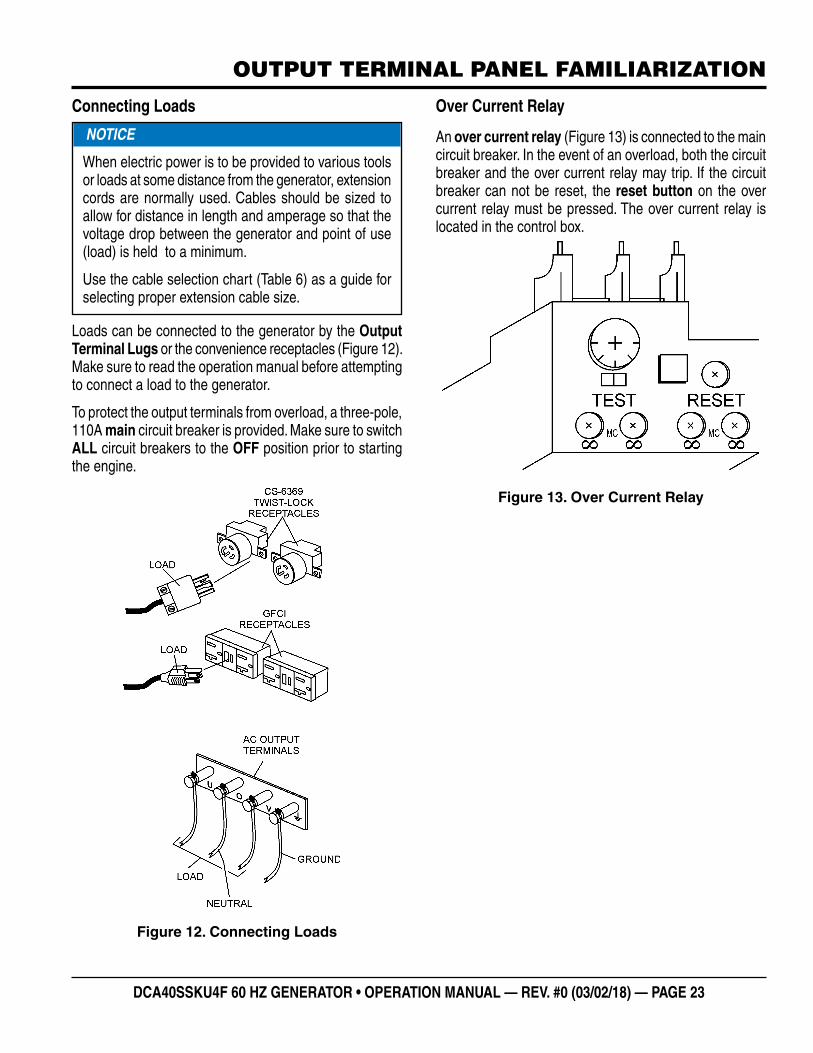
Over Current Relay
An over current relay (Figure 13) is connected to the main circuit breaker. In the event of an overload, both the circuit breaker and the over current relay may trip. If the circuit breaker can not be reset, the reset button on the over current relay must be pressed. The over current relay is located in the control box.
Figure 13. Over Current Relay

PAGE 24 — DCA40SSKU4F 60 HZ GENERATOR • OPERATION MANUAL — REV. #0 (03/02/18)
LOAD APPLICATION
SINGLE PHASE LOAD
Always be sure to check the nameplate on the generator and equipment to insure the wattage, amperage, frequency and voltage requirements are satisfactorily supplied by the generator for operating the equipment.
Generally, the wattage listed on the nameplate of the equipment is its rated output. Equipment may require 130—150% more wattage than the rating on the nameplate, as the wattage is influenced by the efficiency, power factor and starting system of the equipment.
WATTS = VOLTAGE x AMPERAGE
The power factor of this generator is 0.8. SeeTable 5 below when connecting loads.
Table 6. Cable Selection (60 Hz, Single Phase Operation)
Current in
Amperes
Load in Watts Maximum Allowable Cable Length
At 100 Volts
At 200 Volts #10 Wire #12 Wire #14 Wire #16 Wire
2.5 300 600 1000 ft. 600 ft. 375 ft. 250 ft.
5 600 1200 500 ft. 300 ft. 200 ft. 125 ft.
7.5 900 1800 350 ft. 200 ft. 125 ft. 100 ft.
10 1200 2400 250 ft. 150 ft. 100 ft.
15 1800 3600 150 ft. 100 ft. 65 ft.
20 2400 4800 125 ft. 75 ft. 50 ft.
CAUTION: Equipment damage can result from low voltage
NOTICE
If wattage is not given on the equipment’s name plate, approximate wattage may be determined by multiplying nameplate voltage by the nameplate amperage.
Table 5. Power Factor By LoadType of Load Power Factor
Single-phase induction motors 0.4-0.75
Electric heaters, incandescent lamps 1.0Fluorescent lamps, mercury lamps 0.4-0.9Electronic devices, communication equipment 1.0
Common power tools 0.8
THREE PHASE LOAD
When calculating the power requirements for three-phase power, use the following equation:
An inadequate size connecting cable which cannot carry the required load can cause a voltage drop which can burn out the appliance or tool and overheat the cable. See Table 6.
�When connecting a resistance load such as an incandescent lamp or electric heater, a capacity of up to the generating set’s rated output (kW) can be used.
�When connecting a fluorescent or mercury lamp, a capacity of up to the generating set’s rated output (kW) multiplied by 0.6 can be used.
�When connecting an electric drill or other power tools, pay close attention to the required starting current capacity.
When connecting ordinary power tools, a capacity of up to the generating set’s rated output (kW) multiplied by 0.8 can be used.
NOTICE
Motors and motor-driven equipment draw much greater current for starting than during operation.
NOTICE
If 3Ø load (kVA) is not given on the equipment nameplate, approximate 3Ø load may be determined by multiplying voltage by amperage by 1.732.
DANGER
Before connecting this generator to any building’s electrical system, a licensed electrician must install an isolation (transfer) switch. Serious damage to the building’s electrical system may occur without this transfer switch.

DCA40SSKU4F 60 HZ GENERATOR • OPERATION MANUAL — REV. #0 (03/02/18) — PAGE 25
GENERATOR OUTPUTS
GENERATOR OUTPUT VOLTAGES
A wide range of voltages are available to supply voltage for many different applications. Voltages are selected by using the voltage selector switch (Figure 14). To obtain some of the voltages as listed in Table 7 (see below) will require a fine adjustment using the voltage regulator (VR) control knob located on the control panel.
Voltage Selector Switch
The voltage selector switch (Figure 14) is located above the output terminal panel’s Hard Wire Hook-up Panel. It has been provided for ease of voltage selection.
Figure 14. Voltage Selector Switch
Voltage Selector Switch Locking Button
To lock the voltage selector switch, press and hold the red button located at the bottom of the switch. While holding the red button down, insert a pad lock into the hole next to the button to retain it in the inward locked position. When the lock is removed, the red button is spring loaded and will return to its normal outward unlocked position.
CAUTION
NEVER change the position of the voltage selector switch while the engine is running. ALWAYS place circuit breaker in the OFF position before selecting voltage.
Table 7. Voltages AvailableUVWO Output Terminal Lugs
Voltage Selector Switch3-Phase 240/139V Position
Voltage Selector Switch3-Phase 480/270V Position
3Ø Line-Line 208V 220V 240V 416V 440V 480V
1Ø Line-Neutral 120V 127V 139V 240V 254V 277V
Voltage Selector Switch Single-Phase 240/120V Position
1Ø Line-Neutral/Line-Line
120V Line-Neutral N/A N/A 240V
Line-Line N/A N/A
Generator Amperage
Table 8 shows the maximum amps the generator can provide. DO NOT exceed the maximum amps as listed.
GFCI Receptacle Load Capability
The load capability of the GFCI receptacles is directly related to the voltage being supplied at either the output terminals or the two twist lock auxiliary receptacles.
Table 9 and Table 10 show what amount of current is available at the GFCI receptacles when the output terminals and twist lock receptacles are in use. Be careful that your load does not exceed the available current capability at the receptacles.
Table 8. Generator Maximum Amps
Rated Voltage Maximum Amps
1Ø 120 Volt 80 amps (4 wire) 108A x 2 (Zigzag)
1Ø 240 Volt 40 amps (4 wire) 108A (Zigzag)
3Ø 240 Volt 86 amps
3Ø 480 Volt 43 amps
Main Line Circuit Breaker Rating 110 amps
Table 9. 1Ø GFCI Receptacle Load Capacity
KW in Use Twist Lock (C6369)
Available Load Current (Amps)
1Ø 240/120V GFCI Duplex 5-20R 120V
26.0 024.8 5 amps/receptacle
23.6 10 amps/receptacle
22.4 15 amps/receptacle
21.2 20 amps/receptacle
Table 10. 3Ø Generator Maximum Amps
KVA in Use (UVWO Terminals)
Available Load Current (Amps)
3Ø 240/480V GFCI Duplex 5-20R 120V
36 0 amps/receptacle
31.8 5 amps/receptacle
27.7 10 amps/receptacle
23.5 15 amps/receptacle
19.4 20 amps/receptacle

PAGE 26 — DCA40SSKU4F 60 HZ GENERATOR • OPERATION MANUAL — REV. #0 (03/02/18)
GENERATOR OUTPUTS/GAUGE READING
HOW TO READ THE AC AMMETER AND AC VOLTAGE GAUGES
The AC ammeter and AC voltmeter gauges are controlled by the AC ammeter and AC voltmeter change-over switches.
Both of these switches are located on the control panel and DO NOT effect the generator output. They are provided to help observe how much power is being supplied, produced at the UVWO terminal lugs.
Before taking a reading from either gauge, set the Voltage Selector Switch (Figure 15) to the position which produces the required voltage (For example, for 3Ø 240V, choose the center 3Ø 240/139V position on the voltage selector switch).
Figure 15. Voltage Selector Switch 240/139V 3Ø Position
AC Voltmeter Gauge Reading
Place the AC Voltmeter Change-Over Switch (Figure 16) in the W-U position and observe the phase to phase voltage reading between the W and U terminals as indicated on the AC Voltmeter Gauge (Figure 17).
NOTICE
For 3Ø 208V/1Ø,120V, place the Voltage Selector Switch in the 3 Phase 240/139 position.
Figure 16. AC Voltmeter Change-Over Switch
Figure 17. AC Voltmeter Gauge
120
AC Ammeter Gauge Reading
Place the AC Ammeter Change-Over Switch (Figure 18) in the U position and observe the current reading (load drain) on the U terminal as indicated on the AC Ammeter Gauge (Figure 19). This process can be repeated for terminals V and W.
Figure 18. AC Ammeter Change-Over Switch
Figure 19. AC Ammeter (Amp Reading on U Lug)
NOTICE
The ammeter gauge will only show a reading when the Output Terminal Lugs are connected to a load and in use.

DCA40SSKU4F 60 HZ GENERATOR • OPERATION MANUAL — REV. #0 (03/02/18) — PAGE 27
OUTPUT TERMINAL PANEL CONNECTIONS
UVWO TERMINAL OUTPUT VOLTAGES
Various output voltages can be obtained using the UVWO output terminal lugs. The voltages at the terminals are dependent on the position of the Voltage Selector Switch and the adjustment of the Voltage Regulator Control Knob.
Remember, the voltage selector switch determines the range of the output voltage. The voltage regulator (VR) allows the user to increase or decrease the selected voltage.
3Ø-240/139 UVWO Terminal Output Voltages
1. Place the voltage selector switch in the 3Ø 240/139 position as shown in Figure 20.
Figure 20. Voltage Selector Switch 3Ø-240/139V Position
2. Connect the load wires to the UVWO terminals as shown in Figure 21.
Figure 21. UVWO Terminal Lugs 3Ø-240/139V Connections
3. Turn the voltage regulator knob (Figure 22) clockwise to increase voltage output, turn counterclockwise to decrease voltage output. Use the voltage regulator adjustment knob whenever fine tuning of the output voltage is required.
Figure 22. Voltage Regulator Knob
3Ø-208V/1Ø-120V UVWO Terminal Output Voltages1. Place the voltage selector switch in the 3Ø 240/139
position as shown in Figure 23.
Figure 23. Voltage Selector Switch 3Ø-240/139V Position
2. Connect the load wires to the UVWO terminals as shown in Figure 24.
Figure 24. UVWO Terminal Lugs 3Ø-208/1Ø-120V Connections Connections
NOTICE
To achieve a 3Ø 208V output the voltage selector switch must be in the 3Ø-240/139 position and the voltage regulator must be adjusted to 208V.

PAGE 28 — DCA40SSKU4F 60 HZ GENERATOR • OPERATION MANUAL — REV. #0 (03/02/18)
OUTPUT TERMINAL PANEL CONNECTIONS
3Ø-480/277V UVWO Terminal Output Voltages
1. Place the voltage selector switch in the 3Ø 480/277 position as shown in Figure 25.
Figure 25. Voltage Selector Switch 3Ø-480/277V Position
2. Connect the load wires to the UVWO terminals as shown in Figure 26.
Figure 26. UVWO Terminal Lugs 3Ø-440/254V Connections
3. Turn the voltage regulator knob (Figure 22) clockwise to increase voltage output, turn counterclockwise to decrease voltage output. Use voltage regulator adjustment knob whenever fine tuning of the output voltage is required.
1Ø-240/120V UVWO Terminal Output Voltages
1. Place the voltage selector switch in the 1Ø 240/120 position as shown in Figure 27.
Figure 27. Voltage Selector Switch 1Ø-240/120V Position
2. Connect the load wires to the UVWO terminals as shown in Figure 28.
Figure 28. UVWO Terminal Lugs 1Ø-200/100V Connections
3. Turn the voltage regulator knob (Figure 22) clockwise to increase voltage output, turn counterclockwise to decrease voltage output. Use voltage regulator adjustment knob whenever fine tuning of the output voltage is required.
NOTICE
ALWAYS make sure that the connections to the UVWO terminals are secure and tight. The possibility of arcing exists, that could cause a fire.

DCA40SSKU4F 60 HZ GENERATOR • OPERATION MANUAL — REV. #0 (03/02/18) — PAGE 29
INSPECTION/SETUP
CIRCUIT BREAKERSTo protect the generator from an overload, a three-pole, 110 amp, main circuit breaker is provided to protect the U,V, and W output terminals from overload. In addition, two single-pole, 20 amp duplex circuit breakers are provided to protect the GFCI receptacles from overload. Two 50 amp circuit breakers have also been provided to protect the auxiliary receptacles from overload. Make sure to switch ALL circuit breakers to the OFF position prior to starting the engine.
LUBRICATION OILFill the engine crankcase with lubricating oil through the filler hole, but DO NOT overfill. Make sure the generator is level and verify that the oil level is maintained between the two notches (Figure 29) on the dipstick. See Table 11 for proper selection of engine oil.
Figure 29. Engine Oil Dipstick
When checking the engine oil, be sure to check if the oil is clean. If the oil is not clean, drain the oil by removing the oil drain plug, and refill with the specified amount of oil as outlined in the KUBOTA Engine Owner’s Manual. Oil should be warm before draining.Other types of motor oils may be substituted if they meet the following requirements:
� API Service Classification CC/SC �API Service Classification CC/SD �API Service Classification CC/SE �API Service Classification CC/SF
Table 11. Recommended Motor Oil
FUEL CHECK
Refilling the Fuel System
This generator has an internal fuel tank located inside the generator enclosure frame and may also be equipped with an environmental fuel tank (Figure 30). ALWAYS fill the fuel tanks with clean fresh #2 diesel fuel. DO NOT fill the fuel tanks beyond their capacities.
Pay attention to the fuel tank capacity when replenishing fuel. The fuel tank cap must be closed tightly after filling. Handle fuel in a safety container. If the container does not have a spout, use a funnel. Wipe up any spilled fuel immediately.
Figure 30. Internal Fuel Tank System
DANGER
Fuel spillage on a hot engine can cause a fire or explosion. If fuel spillage occurs, wipe up the spilled fuel completely to prevent fire hazards. NEVER smoke around or near the generator.
CAUTION
ONLY properly trained personnel who have read and understand this section should refill the fuel tank system.
INTERNALFUEL TANK
FUELCAP
40

PAGE 30 — DCA40SSKU4F 60 HZ GENERATOR • OPERATION MANUAL — REV. #0 (03/02/18)
INSPECTION/SETUP
Refueling Procedure:
1. Level Tanks — Make sure fuel cells are level with the ground. Failure to do so will cause fuel to spill from the tank before reaching full capacity (Figure 31).
Figure 31. Only Fill on Level Ground
WARNING
Diesel fuel and its vapors are dangerous to your health and the surrounding environment. Avoid skin contact and/or inhaling fumes.
CAUTION
ALWAYS place trailer on firm level ground before refueling to prevent spilling and to maximize the amount of fuel that can be pumped into the tank.
Level GroundUnlevel Ground =
Level GroundUnlevel Ground
DO NOT fill onunlevel ground
!!
15040
NOTICE
ONLY use low sulfur or ultra low sulfur diesel fuel when refueling.
2. Open cabinet doors on the “right side” of the generator (from generator control panel position). Remove fuel cap and fill tank as shown in Figure 32.
Figure 32. Fueling the Generator
3. NEVER overfill fuel tank — It is important to read the fuel gauge when filling trailer fuel tank. DO NOT wait for fuel to rise in filler neck (Figure 33).
Figure 33. Full Fuel Tank
Figure 34. Fuel Expansion
DIESELFUEL
CAUTION
DO NOT OVERFILL fuel system. Leave room for fuel expansion. Fuel expands when heated (Figure 34).

DCA40SSKU4F 60 HZ GENERATOR • OPERATION MANUAL — REV. #0 (03/02/18) — PAGE 31
COOLANT (ANTIFREEZE/SUMMER COOLANT/WATER)
KUBOTA recommends antifreeze/summer coolant for use in their engines, which can be purchased in concentrate (and mixed with 50% demineralized water) or pre-diluted. See the KUBOTA Engine Owner’s Manual for further details.
Day-to-day addition of coolant is done from the recovery tank. When adding coolant to the radiator, DO NOT remove the radiator cap until the unit has completely cooled. See Table 12 for engine, radiator, and recovery tank coolant capacities. Make sure the coolant level in the recovery tank is always between the “H” and the “L” markings.
Operation in Freezing Weather
When operating in freezing weather, be certain the proper amount of antifreeze (Table 13) has been added.
WARNING
If adding coolant/antifreeze mix to the radiator, DO NOT remove the radiator cap until the unit has completely cooled. The possibility of hot! coolant exists which can cause severe burns.
Table 12. Coolant CapacityEngine and Radiator 4.75 gal (18 liters)
Reserve Tank N/A
Table 13. Anti-Freeze Operating Temperatures
Vol % Anti-
Freeze
Freezing Point Boiling Point
°C °F °C °F
50 -37 -34 108 226
NOTICE
When the antifreeze is mixed with water, the antifreeze mixing ratio must be less than 50%.
CLEANING THE RADIATOR
The engine may overheat if the radiator fins become overloaded with dust or debris. Periodically clean the radiator fins with compressed air. Cleaning inside the machine is dangerous, so clean only with the engine turned off and the negative battery terminal disconnected.
AIR CLEANER
Periodic cleaning/replacement is necessary. Inspect it in accordance with the KUBOTA Engine Owner’s Manual.
FAN BELT TENSION
A slack fan belt may contribute to overheating or insufficient charging of the battery. Inspect the fan belt for damage and wear. Adjust fan belt in accordance with the KUBOTA Engine Owner’s Manual.
The fan belt tension is proper if the fan belt bends 10 to 15 mm (Figure 35) when depressed with the thumb as shown below.
Figure 35. Fan Belt Tension
0.4~0.6 IN.(10~15MM)
DEFLECTION
CAUTION
NEVER place hands near the belts or fan while the generator set is running.
INSPECTION/SETUP

PAGE 32 — DCA40SSKU4F 60 HZ GENERATOR • OPERATION MANUAL — REV. #0 (03/02/18)
BATTERY
This unit is of negative ground, DO NOT connect in reverse. Always maintain battery fluid level between the specified marks. Battery life will be shortened if the fluid levels are not properly maintained. Add only distilled water when replenishment is necessary.
DO NOT over fill. Check to see whether the battery cables are loose. Poor contact may result in poor starting or malfunctions. Always keep the terminals firmly tightened. Coat the terminals with an approved battery terminal treatment compound. Replace battery only with recommended type battery.
The battery is sufficiently charged if the specific gravity of the battery fluid is 1.28 (at 68° F). If the specific gravity should fall to 1.245 or lower, it indicates that the battery is dead and needs to be recharged or replaced.
Before charging the battery with an external electric source, be sure to disconnect the battery cables.
Battery Cable Installation
ALWAYS be sure the battery cables (Figure 36) are properly connected to the battery terminals as shown below. The red cable is connected to the positive terminal of the battery and the black cable is connected to the negative terminal of the battery.
Figure 36. Battery Connections
CAUTION
ALWAYS disconnect the negative terminal FIRST and reconnect the negative terminal LAST.
POSITIVE
NEGATIVE
When connecting battery do the following:
1. NEVER connect the battery cables to the battery terminals when the MPEC Control Switch is in the MANUAL position. ALWAYS make sure that the MPEC Control Switch is in the OFF/RESET position when connecting the battery.
2. Place a small amount of battery terminal treatment compound around both battery terminals. This will ensure a good connection and will help prevent corrosion around the battery terminals.
ALTERNATOR
The polarity of the alternator is negative grounding type. When an inverted circuit connection takes place, the circuit will be in short circuit instantaneously resulting in alternator failure.
DO NOT put water directly on the alternator. Entry of water into the alternator can cause corrosion and damage the alternator.
WIRING
Inspect the entire generator for bad or worn electrical wiring or connections. If any wiring or connections are exposed (insulation missing), replace wiring immediately.
PIPING AND HOSE CONNECTION
Inspect all piping, oil hose and fuel hose connections for wear and tightness. Tighten all hose clamps and check hoses for leaks.
If any hose (fuel or oil) lines are defective, replace them immediately.
NOTICE
If the battery cable is connected incorrectly, electrical damage to the generator will occur. Pay close attention to the polarity of the battery when connecting the battery.
CAUTION
Inadequate battery connections may cause poor starting of the generator and create other malfunctions.
INSPECTION/SETUP

DCA40SSKU4F 60 HZ GENERATOR • OPERATION MANUAL — REV. #0 (03/02/18) — PAGE 33
GENERATOR START-UP PROCEDURE (MANUAL)
BEFORE STARTING
1. Place the Main, Aux. and Duplex circuit breakers (Figure 37) in the OFF position prior to starting the engine.
Figure 37. Main, Aux. and Duplex Circuit Breakers (OFF)
2. Connect the load to the receptacles or the output terminal lugs as shown in Figure 12. These load connection points can be found on the output terminal panel and the output terminal panel’s hard wire hookup panel.
3. Tighten terminal nuts securely to prevent load wires from slipping out.
4. Close all engine enclosure doors (Figure 38).
Figure 38. Engine Enclosure Doors
CAUTION
The engine’s exhaust contains harmful emissions. ALWAYS have adequate ventilation when operating. Direct exhaust away from nearby personnel.
WARNING
NEVER manually start the engine with the main, duplex or auxiliary circuit breakers in the ON (closed) position.
MAINCIRCUIT
BREAKER
DUPLEXCIRCUIT
BREAKERS
CS-6369AUX. CIRCUIT
BREAKERS
OF
F
OF
F
OF
F
OF
F
OF
F
OF
F
OF
F
INCORRECTCORRECT
STARTING (MANUAL)1. Place the voltage selector switch in the desired
voltage position (Figure 39).
Figure 39. Voltage Selector Switch
2. Place the engine speed switch (Figure 40) in the LOW (down) position.
Figure 40. Engine Speed Switch (Low)
3. Place the Auto-Off/Reset Manual Switch in the MANUAL position to start the engine (Figure 41).
Figure 41. Auto-Off/Reset Manual;Switch (Manual Position)
4. Depending on the temperature of the coolant (cold weather conditions), the pre-heat LED (Figure 42) will light (ON) and remain on until the pre-heating cycle has been completed. After completion of the pre-heating cycle, the LED will go OFF and the engine will start.
Figure 42. Pre-Heat LED Engine Warning Unit
LOW (DOWN)
AUTO MANUAL
OFF/RESET
PRE-HEATLED

PAGE 34 — DCA40SSKU4F 60 HZ GENERATOR • OPERATION MANUAL — REV. #0 (03/02/18)
GENERATOR START-UP PROCEDURE (MANUAL)
5. In warm weather conditions, let the engine run for 1-2 minutes. Listen for any abnormal noises. If any abnormalities exist, shut down the engine and correct the problem.
6. Verify that the engine started status LED on the ECU controller is on (Figure 43).
Figure 43. ECU Controller (Engine Started LED)
7. If the engine is running smoothly, place the engine speed switch (Figure 44) in the HIGH (up) position.
Figure 44. Engine Speed Switch (High)
NOTICE
In cold weather conditions, warm up the engine 5-7 minutes before placing into operation.
Low Oil Pressure
High Temp.
Over Crank
Over Speed
Engine Started
ECU Intergrated Gauge Control
R
NOTICE
If the engine fails to start after three attempts, the over-crank LED on the ECU controller will turn on and the Auto-Off/Reset Switch must be placed in the Off/Reset position before the engine can be restarted.
HIGH (UP)
8. The generator’s frequency meter (Figure 45) should be displaying the 60 cycle output frequency in HERTZ.
Figure 45. Frequency Meter
9. The generator’s AC-voltmeter (Figure 46) will display the generator’s output in VOLTS.
Figure 46. Voltmeter Meter
10. If the voltage is not within the specified tolerance, use the voltage adjustment control knob (Figure 47) to increase or decrease the desired voltage.
Figure 47. Voltage Adjust Control Knob
11. The ammeter (Figure 48) will indicate zero amps with no load applied. When a load is applied, the ammeter will indicate the amount of current that the load is drawing from the generator.
Figure 48. Ammeter (No Load)
60 Hz
120

DCA40SSKU4F 60 HZ GENERATOR • OPERATION MANUAL — REV. #0 (03/02/18) — PAGE 35
12. Place the Main, Aux. and Duplex circuit breakers in the ON position (Figure 49).
Figure 49. Main, Aux. and Duplex Circuit Breakers (ON)
13. Observe the generator’s ammeter (Figure 50) and verify it reads the anticipated amount of current with respect to the load. The ammeter will only display a current reading if a load is in use.
Figure 50. Ammeter (Load)
14. The generator will run until manually stopped or an abnormal condition occurs.
MAINCIRCUIT
BREAKER
DUPLEXCIRCUIT
BREAKERS
CS-6369AUX. CIRCUIT
BREAKERS
ON
ON
ON
ON
ON
ON
ON
GENERATOR START-UP PROCEDURE (MANUAL)

PAGE 36 — DCA40SSKU4F 60 HZ GENERATOR • OPERATION MANUAL — REV. #0 (03/02/18)
DANGER
Before connecting this generator to any building’s electrical system, a licensed electrician must install an isolation (transfer) switch. Serious damage to the building’s electrical system may occur without this transfer switch.
NOTICE
When connecting the generator to a isolation (transfer) switch, ALWAYS have power applied to the generator’s internal battery charger. This will ensure that the engine will not fail due to a dead battery.
NOTICE
When the Auto Off/Reset Manual switch is placed in the AUTO mode, the generator will automatically start in the event of commercial power falling below a prescribed level by means of a contact closure that is generated automatically by a transfer switch.
In this position (AUTO), should an outage occur, the automatic transfer switch (ATS) will start the generator automatically via the generator's auto-start contacts connected to the ATS's start contacts.
Please refer to your ATS installation manual for further instructions for the correct installation of the auto-start contacts of the generator to the ATS.
WARNING
When running the generator in the AUTO mode, remember the generator can start up at any time without warning. NEVER attempt to perform any maintenance when the generator is in the auto mode.
NOTICE
When the Auto Off/Reset Manual switch is placed in the AUTO position, the engine glow plugs will be warmed and the engine will start automatically.
GENERATOR START-UP PROCEDURE (AUTO)
STARTING (AUTO MODE)
When starting the generator in AUTO mode, use the “Manual Start-up” procedure except where noted (see below).
1. Perform steps 1 through 5 in the Before Starting section as outlined in the Manual Starting Procedure.
2. Place the Auto Off/Reset Manual Switch (Figure 51) in the AUTO position.
Figure 51. Auto Off/Reset Manual Switch (AUTO)
3. Continue operating the generator as outlined in the Manual Start-up procedure (start at step 8).
NOTICE
The engine speed switch must be set to the “High” (up)position when running in the auto-start mode. Failing to set the switch in the proper position can result in damage to your generator when it turns on.
AUTO MANUAL
OFF/RESET

DCA40SSKU4F 60 HZ GENERATOR • OPERATION MANUAL — REV. #0 (03/02/18) — PAGE 37
NORMAL SHUTDOWN PROCEDURE
To shutdown the generator, use the following procedure:
1. Place the Main, Aux. and Duplex circuit breakers (Figure 52) in the OFF position.
Figure 52. Main, Aux. and Duplex Circuit Breakers (OFF)
2. Place the engine speed control switch (Figure 53) in the Start/Idle position (down).
Figure 53. Engine Speed Switch Start/Idle Position
3. Let the engine cool by running it at low speed for 3-5 minutes with no load applied.
4. Place the Auto-Off/Reset Manual Switch in the OFF/Reset position (Figure 54) to start the engine.
Figure 54. Auto-Off/Reset Manual Switch (Off/Reset Position)
5. Remove all loads from the generator.
6. Inspect entire generator for any damage or loosening of components that may have occurred during operation.
NOTICE
NEVER stop the engine suddenly except in an emergency.
MAINCIRCUIT
BREAKER
DUPLEXCIRCUIT
BREAKERS
CS-6369AUX. CIRCUIT
BREAKERS
OF
F
OF
F
OF
F
OF
F
OF
F
OF
F
OF
F
LOW (DOWN)
AUTO MANUAL
OFF/RESET
EMERGENCY SHUTDOWN PROCEDURE
1. If equipped (option), push the Emergency Stop Pushbutton Switch (Figure 55).
Figure 55. Emergency Stop Button
2. If unit is not equipped with an emergency stop switch, place the Auto Off/Reset Manual Switch (Figure 51) in the Off/Reset position.
AUTOMATIC SHUT-DOWN SYSTEM
This unit is equipped with safety devices to automatically stop the engine in the event of low oil pressure, approximately 14.2 psi (96.5 kPa), or high water temperature, approximately 212° F (100° C). The LED alarm indicators on the Engine Control Unit (ECU) illuminate to signify the reason for the shutdown.
NOTICE
Before inspecting, place all circuit breakers in the OFF position and allow sufficient time for adequate cooling. When ready to restart, complete all steps in the Generator Startup Procedure section of this manual.
GENERATOR SHUT-DOWN PROCEDURES

PAGE 38 — DCA40SSKU4F 60 HZ GENERATOR • OPERATION MANUAL — REV. #0 (03/02/18)
Table 14. Inspection/Maintenance10 Hrs DAILY
250 Hrs500 Hrs or Every
12 Months
3000 Hrs or Every
36 MonthsOTHER
Engine
Check Engine Oil and Coolant Levels X
Check Fuel Filter/Water Separator Bowl X
Check Air Cleaner X
Check Air Cleaner Element X
Check for Leaks/Hoses/Clamps X
Check for Loosening of Parts X
Change Engine Oil and Oil Filter * 1 X
Clean Unit, Inside and Outside X
Replace Fuel Filter Elements X
Check Engine Mounts X
Service Battery X
Check Air Intake Hoses X
Check Fan Belt Condition X
Check Automatic Belt Tensioner X
Check Electrical Ground Connection X
Clean Radiator, Check Cooling System X
Coolant Solution Analysis, Add SCA's As Required X
Pressure Test Cooling System X
Check Engine Speed X
Test Thermostat 6000 hrs.
Check and Adjust Engine Valve Clearance X
Test Glow Plugs X
Replace Diesel Oxidation Catalyst (DOC) * 2 4500 hrs.
Flush and Refill Cooling System 2 yrs. or 2000 hrs.
Clean Inside of Fuel Tank 1000 hrs.
Check Crankcase Ventilation Filter X .
Replace Air Cleaner Elements * 3 As Required
GeneratorMeasure Insulation Resistance Over 3M ohms X
Check Rotor Rear Support Bearing X s
*1 During initial operation of a new engine, change oil and filter between a minimum of 100 hrs. and a maximum of 500 hrs. Service interval depends on type of oil.
*2 Expectation for minimal service interval will be at least 4500 hrs. based on engine power. However, actual service should take place when indicated by diagnostic gauge. Please contact nearest authorized Multiquip Service Center for DOC Cleaning.
*3 Replace primary air filter element when restriction indicator shows a vacuum of 625 mm (25 in. H20).
MAINTENANCE

DCA40SSKU4F 60 HZ GENERATOR • OPERATION MANUAL — REV. #0 (03/02/18) — PAGE 39
MAINTENANCE
GENERAL INSPECTIONPrior to each use, the generator should be cleaned and inspected for deficiencies. Check for loose, missing or damaged nuts, bolts or other fasteners. Also check for fuel, oil, and coolant leaks. Use Table 14 as a general maintenance guideline Engine Side (Refer to the Engine Instruction Manual).
AIR CLEANER
Every 250 hours: Remove air cleaner element (Figure 56) and clean the heavy duty paper element with light spray of compressed air. Replace the air cleaner as needed. This Kubota diesel engine is equipped with a replaceable, high-density paper air cleaner element. This air cleaner is also equipped with an inner element (secondary) that is used as a backup filter should the primary element becomes damaged.
Primary and Secondary Air Cleaner Elements
1. Release the latches (Figure 56) that secures the cover to the air cleaner body.
2. Remove the air cleaner cover and set aside.
3. Remove both the primary and secondary air cleaner elements.
4. Check the air cleaner daily or before starting the engine.
5. Check for and correct heavy buildup of dirt and debris along with loose or damaged components.
NOTICE
If the engine is operating in very dusty or dry grass conditions, a clogged air cleaner will result. This can lead to a loss of power, excessive carbon buildup in the combustion chamber and high fuel consumption. Change air cleaner more frequently if these conditions exist.
CAUTION
Wear protective equipment such as approved safety glasses or face shields and dust masks or respirators when cleaning air filters with compressed air.
6. To clean the primary element (paper air filter) as referenced in (Figure 56), tap the filter element several times on a hard surface to remove dirt or blow compressed air not to exceed 30 psi (207 kPa, 2.1 kgf/cm2) through the filter element from the inside out.
Figure 56. Air Cleaner
7. Clean the secondary element (paper air filter) as referenced in step 6.
8. Replace both elements if they are damaged or excessively dirty.
9. Clean the inside of the air cleaner body.
10. Reinstall the primary and secondary air filter elements back into air cleaner body.
11. Reinstall the air cleaner cover and secure with latches.
NOTICE
Operating the engine with loose or damaged air cleaner components could allow unfiltered air into the engine causing premature wear and failure.
EVACUATORVALVE
PRIMARYAIR FILTERELEMENT
BLOW COMPRESSEDAIR FROM THE
INSIDE OUT
SECONDARYAIR FILTERELEMENT
LATCHCOVER
BODY

PAGE 40 — DCA40SSKU4F 60 HZ GENERATOR • OPERATION MANUAL — REV. #0 (03/02/18)
ENGINE FUEL FILTER REPLACEMENT
1. Clean the area around the lubricating fuel filter head.2. Using an oil filter wrench (Figure 57), remove fuel filter.
Figure 57. Fuel Filter Removal
3. Coat the rubber seal (gasket) surface of the fuel filter with clean 15W-40 engine oil.
4. Install new oil filter first by hand until it makes contact with the filter head surface. Tighten it another 3/4 turn using the filter wrench.
FUEL FILTER/WATER SEPARATOR
Inspect the fuel filter water separator daily. If the fuel filter/water separator (Figure 58) has collected a significant amount of water and sediment at the bottom of the cup (indicator mark), it should be drained off.
Draining Of Fuel Water Separator
1. Place the Open/Close fuel valve lever (Figure 58) in the CLOSED position.
ENGINEFUEL FILTERCARTRIDGE
COAT SEALWITH THIN
LAYER OF OIL
OIL
FUEL FILTERHEAD
NOTICE
As water is collected, the red float goes up. When the float has reached the indicator mark (Figure 58), immediately drain the fuel water separator.
2. Loosen the screw at the top of the filter head and also loosen the drain cock located at the bottom of the filter.
3. Let the residue or foreign substances inside the cup flow into a suitable container.
4. Tighten screw and place fuel valve lever in the OPEN position.
Figure 58. Fuel Filter/Water Separator
Cleaning Fuel Water Separator
1. Place the fuel valve lever in the CLOSED position.
2. Remove cup from filter head assembly.
3. Clean inside of cup with a light oil.
4. Clean the area around the fuel filter water separator head.
5. Reattach cup to filter head assembly.
6. Place the fuel valve lever in the OPEN position.
7. Air-bleed fuel system before starting engine.
FLOAT
CUP
SCREW
INDICATORMARK
DRAINCOCK
FUEL VALVELEVER
CLOSED FILTER HEAD
NOTICE
If air enters the fuel injection system of a diesel engine, starting becomes impossible. After running out of fuel or after disassembling the fuel system, air-bleed the fuel system in accordance with the KUBOTA Engine Service Manual.
To restart engine after running out of fuel, place the Auto-Off/Reset Manual Switch in the MANUAL position. Try again, if needed.
MAINTENANCE

DCA40SSKU4F 60 HZ GENERATOR • OPERATION MANUAL — REV. #0 (03/02/18) — PAGE 41
Removing Water from the Fuel Tank
After prolonged use, water and other impurities accumulate in the bottom of the tank. Occasionally, inspect the fuel tank for water contamination and drain the contents if required.
During cold weather, the more empty volume inside the tank, the easier it is for water to condense. This can be reduced by keeping the tank full with diesel fuel.
Cleaning Inside the Fuel Tank
If necessary, drain the fuel inside the fuel tank completely. Using a spray washer (Figure 59), wash out any deposits or debris that have accumulated inside the fuel tank.
Figure 59. Fuel Tank Cleaning
FUEL TANK INSPECTION
In addition to cleaning the fuel tank, the following components should be inspected for wear:
�Rubber Suspension — look for signs of wear or deformity due to contact with oil. Replace the rubber suspension if necessary.
� Fuel Hoses — inspect nylon and rubber hoses for signs of wear, deterioration and hardening.
� Fuel Tank Lining — inspect the fuel tank lining for signs of excessive amounts of oil or other foreign matter.
FUEL TANK
V-BELT (DAILY)
Visually examine the V-belt (Figure 60) and determine if it is full of tiny cracks, frayed, has pieces of rubber missing, is peeling or is otherwise damaged.
Also, examine the belt and determine if it is oil soaked or "glazed " (hard shiny appearance on the sides of the belt). Either of these two conditions can cause the belt to run hot, which can weaken it and increase the danger of it breaking.
If the V-belt exhibits any of the above wear conditions, replace the V-belt immediately.
Figure 60. V-Belt Inspection
ENGINE OIL (CHECK DAILY)
1. When checking or adding oil, place the machine so the engine is level.
2. Pull the engine oil dipstick from its holder.3. Determine if engine oil is low. Oil level should be
between the upper and lower limit (Figure 61) on the dipstick.
Figure 61. Dipstick Engine Oil Level
GLAZED
OIL SOAKED
BROKEN
CORD FAILURE
CRACKSMISSING RUBBER
SIDEWALLWEAR
WORN BACKCOVER
H (UPPER LIMIT)
L (LOWER LIMIT)
DO NOTOVERFILL
MAINTENANCE

PAGE 42 — DCA40SSKU4F 60 HZ GENERATOR • OPERATION MANUAL — REV. #0 (03/02/18)
4. If oil level is low, add correct amount of engine oil to bring oil level to a normal safe level (See Recommended Viscosity Grades), Table 15.
5. Allow enough time for any added oil to make its way to the oil pan before rechecking.
Table 15. Oil Selection Chart
DRAINING ENGINE OIL
1. Run the engine until the engine coolant reaches a temperature of 140° (60°C). Turn the engine off.
2. Remove the oil dipstick from its holder.3. Next, remove oil drain bolt and sealing washer to allow
the oil to drain into a suitable container.
Figure 62. Draining Engine Oil
4. After engine oil has been completely drained, reinstall drain bolt with sealing washer and tighten securely.
-40
-30
-10
-20
-22
-40
-4
-14
032
50
68
86
104
122
10
20
30
40
50
F C
5W
/30
5W
/40
10W
10W
/30
10W
/40
15W
/40
20W
/20 3
0 40
OIL: SAE
DRAINBOLT
SEALINGWSHER
NOTICE
For composite oil pans, always install a new sealing washer.
MAINTENANCE
ENGINE OIL FILTER REPLACEMENT
1. Clean the area around the lubricating oil filter head.2. Using an oil filter wrench (Figure 63), remove engine
oil filter.
Figure 63. Engine Oil Filter Removal
3. Coat the rubber seal (gasket) surface of oil filter (Figure 63), with clean 15W-40 engine oil.
4. Install new oil filter first by hand until it makes contact with the filter head surface. Tighten it another 3/4 turn using the filter wrench.
5. Fill engine crankcase with high quality detergent oil classified "For Service CJ-4". Fill to the upper limit of dipstick but DO NOT overfill. Reference Table 2 for engine crankcase oil capacity.
6. Run the engine for several minutes. Watch for oil leakage. Shut the engine down and allow it to sit for several minutes. Top off the oil to the upper limit on the dipstick.
ENGINEOIL FILTER
CARTRIDGE
RUBBERSEAL
COAT SEALWITH THIN
LAYER OF OILOIL FILTER WRENCH
OIL

DCA40SSKU4F 60 HZ GENERATOR • OPERATION MANUAL — REV. #0 (03/02/18) — PAGE 43
FLUSHING OUT RADIATOR AND REPLACING COOLANT
1. Remove the coolant (Figure 64), OPEN the drain bolt or OPEN the drain valve on the radiator and allow the coolant to drain into a suitable container.
Figure 64. Draining Engine Coolant
2. Check hoses for softening and kinks. Check clamps for signs of leakage.
3. Tighten water cock and replace the overflow tank.
4. Replace with coolant as recommended by the engine manufacturer.
5. Close radiator cap tightly.
6. Flush the radiator by running clean tap water through radiator until signs of rust and dirt are removed. DO NOT clean radiator core with any objects, such as a screwdriver.
WARNING
DO NOT remove the pressure cap from the radiator when the engine is hot! Wait until the coolant temperature is below 120°F (50°C) before removing pressure cap.
Heated coolant spray or steam can cause severe scalding and personal injury.
DRAINBOLT
RADIATOR CLEANING
The radiator (Figure 65), should be sprayed (cleaned) with a high pressure washer when excessive amounts of dirt and debris have accumulated on the cooling fins or tube. When using a high pressure washer, stand at least 5 feet (1.5 meters) away from the radiator to prevent damage to the fins and tube.
Figure 65. Radiator Cleaning
WARNING
Allow engine to cool when flushing out radiator. Flushing the radiator while hot could cause serious burns from water or steam.
MAINTENANCE

PAGE 44 — DCA40SSKU4F 60 HZ GENERATOR • OPERATION MANUAL — REV. #0 (03/02/18)
ENGINE BLOCK HEATING ELEMENT AND INTERNAL BATTERY CHARGER 120 VAC INPUT RECEPTACLES (OPTIONAL)
This generator can be equipped as an option with a engine block heating element and an internal battery charger. They are provided with electric cords to connect to a commercial power source.
The engine block heating element and internal battery charger both require 120 VAC in order to operate. A receptacle (Figure 66) has been provided on the output terminal panel to allow commercial power to be applied.
These units will ONLY function when commercial power has been supplied to them. When using extension cords, refer to Table 6 for the correct size and length.
When using the generator in hot climates, there is no need to apply power to jacket water heater. However, if the generator will be used in cold climates, it is best to apply power to the jacket water heater at all times.
If the generator will be used daily, the battery should normally not require charging. If the generator will be idle (not used) for long periods of time, apply power to the battery charger receptacle via commercial power using a power cord of adequate size.
Figure 66. Battery Charger and Jacket Water Heater (Option)
GENERATOR STORAGE
For long term storage of the generator the following is recommended:
�Drain the fuel tank completely. Treat with a fuel stabilizer if necessary.
�Completely drain the oil from the crankcase and refill if necessary with fresh oil.
�Clean the entire generator, internal and external.
�Cover the generating set and store in a clean, dry place.
�Disconnect the battery.
�Make sure engine coolant is at proper level.
� If generator is mounted on a trailer, jack trailer up and place on blocks so tires do not touch the ground or block and completely remove the tires.
NOTICE
If the generator will be idle (not used) for long periods of time and to ensure adequate starting capability, always have power applied to the generator's internal battery charger.
BATTERY CHARGER
BATTERY CHARGER/ENGINE BLOCK
HEATING ELEMENT120 VAC INPUTRECEPTACLE
OUTPUT TERMINALPANEL ASSEMBLY
ENGINE BLOCKHEATING ELEMENT
DCAM
PERES
TO STARTER “B”TERMINAL
RED 16 AWG.
TO CHASSISGROUND
GREEN 16 AWG.
MAINTENANCE

DCA40SSKU4F 60 HZ GENERATOR • OPERATION MANUAL — REV. #0 (03/02/18) — PAGE 45
EMISSION CONTROL
The emission control system employed with this Kubota diesel engine consists of a Diesel Oxidation Catalyst (DOC).
The DOC device (Figure 67), helps in filtering out large amounts of harmful Nitrogen Oxides (NOx) and Particulate Matter (PM) which are emitted by diesel engines. These exhaust emissions pose serious environmental and health risks. It is important to maintain and service the DOC emission safety device on a periodic basis.
Diesel Oxidation Catalyst (DOC)
The DOC does not filter particles, it oxidizes them. This catalyst (honeycomb like structure), uses a chemical process to break down pollutants in the exhaust stream into less harmful components. In general, this catalyst collects/burns accumulated particulates. The DOC contains palladium and platinum which serves as a catalyst to
oxidize hydrocarbons and carbon monoxide.
EMISSION CARBON CHECK
Deposition of carbon (soot, unburned fuel) in the exhaust pipe line and muffler, could cause not only system derates but also could lead to fires.
To reduce soot and unburned fuel, run the unit at rated power until the exhaust gas becomes mostly colorless every 250 hours of operation time. More carbon will be generated when the unit operates at less then 30% of rated power. In this case, perform the above procedures more frequently.
NOTICE
Applying a large load suddenly to the unit when the carbon deposition is generated in the exhaust system, could produce sparks and will lead to abnormal combustion. Therefore, apply load gradually and observe the exhaust gas color during the process.
NOTICE
Sparks may come out of the exhaust gas outlet during load operation. Make sure the area surrounding the unit is free from any flammable material.
Figure 67. Diesel Oxidation Catalyst (DOC)
MAINTENANCE

PAGE 46 — DCA40SSKU4F 60 HZ GENERATOR • OPERATION MANUAL — REV. #0 (03/02/18)
MAINTENANCE
MANUAL REGENERATION PROCEDURE
If the manual regeneration request LED (Figure 68) illuminates during operation, indicates that a manual regeneration process is required. Perform the following:
Figure 68. Manual Regen LED
1. Place the Main, Aux. and Duplex circuit breakers (Figure 69) in the OFF position.
Figure 69. Main, Aux. and Duplex Circuit Breakers (OFF/Regen)
NOTICE
DO NOT perform regeneration in conditions where it may be unsafe due to high exhaust temperatures.
NOTICE
The area above and around the generator during the regeneration process should be free of any type of debris, flammable or combustible materials, as temperatures during the regeneration process can reach as high as 1,022 °F (550 °C).
MANUAL REGENREQUEST LED
MAINCIRCUIT
BREAKER
DUPLEXCIRCUIT
BREAKERS
CS-6369AUX. CIRCUIT
BREAKERS
OF
F
OF
F
OF
F
OF
F
OF
F
OF
F
OF
F
2. Remove all loads from the generator.
3. Press the regen start pushbutton and verify that the regeneration request LED remains on.
Figure 70. Regen Start Pushbutton
4. The manual regeneration process will automatically run for at least 30 minutes. Verify that manual regeneration request LED is OFF at the completion of the regeneration process.
NOTICE
The manual regeneration process will stop if a load is applied to the generator.
REGEN STARTPUSHBUTTON
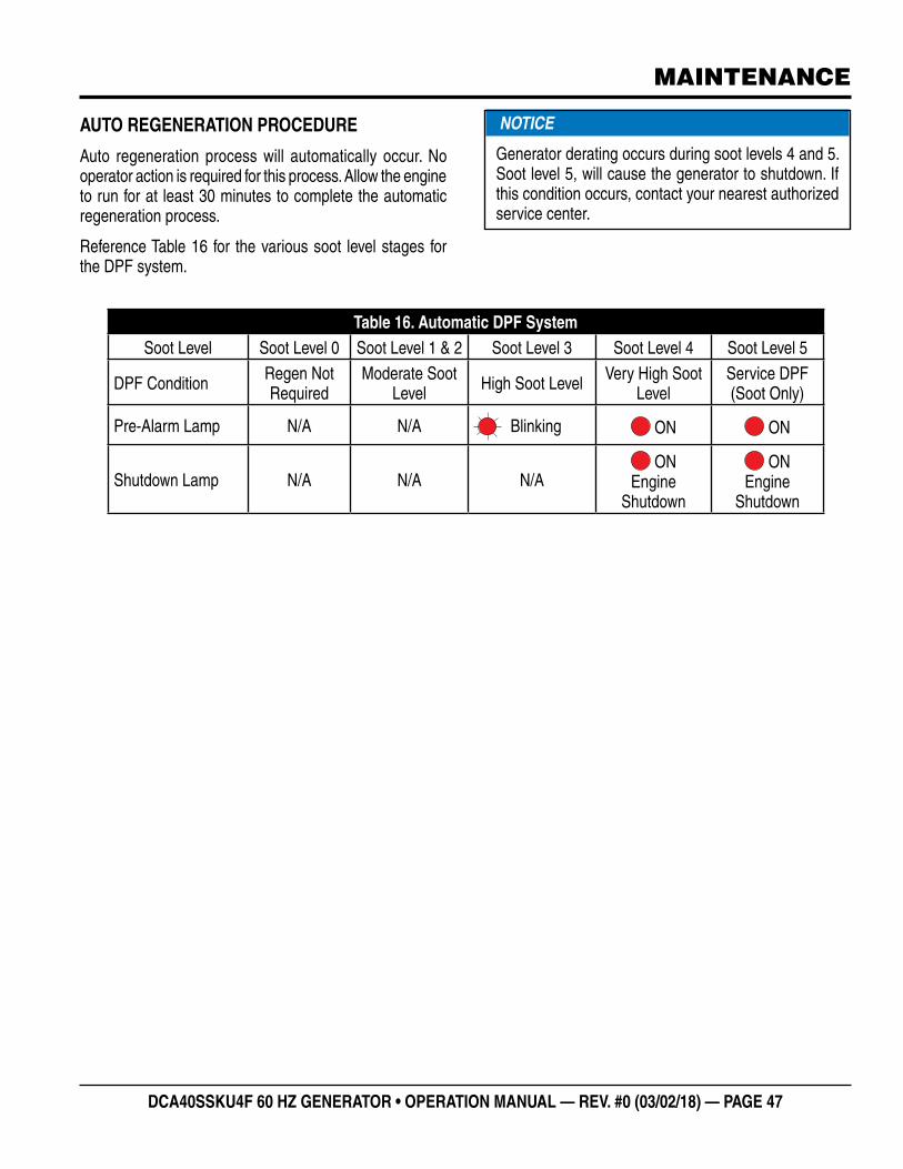
DCA40SSKU4F 60 HZ GENERATOR • OPERATION MANUAL — REV. #0 (03/02/18) — PAGE 47
MAINTENANCE
AUTO REGENERATION PROCEDURE
Auto regeneration process will automatically occur. No operator action is required for this process. Allow the engine to run for at least 30 minutes to complete the automatic regeneration process.
Reference Table 16 for the various soot level stages for the DPF system.
NOTICE
Generator derating occurs during soot levels 4 and 5. Soot level 5, will cause the generator to shutdown. If this condition occurs, contact your nearest authorized service center.
Table 16. Automatic DPF SystemSoot Level Soot Level 0 Soot Level 1 & 2 Soot Level 3 Soot Level 4 Soot Level 5
DPF Condition Regen Not Required
Moderate Soot Level High Soot Level Very High Soot
LevelService DPF (Soot Only)
Pre-Alarm Lamp N/A N/A Blinking ON ON
Shutdown Lamp N/A N/A N/A ON
Engine Shutdown
ON Engine
Shutdown
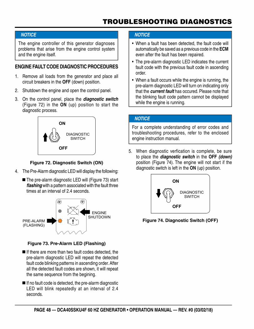
PAGE 48 — DCA40SSKU4F 60 HZ GENERATOR • OPERATION MANUAL — REV. #0 (03/02/18)
TROUBLESHOOTING DIAGNOSTICS
ENGINE FAULT CODE DIAGNOSTIC PROCEDURES
1. Remove all loads from the generator and place all circuit breakers in the OFF (down) position.
2. Shutdown the engine and open the control panel.
3. On the control panel, place the diagnostic switch (Figure 72) in the ON (up) position to start the diagnostic process.
Figure 72. Diagnostic Switch (ON)
4. The Pre-Alarm diagnostic LED will display the following:
� The pre-alarm diagnostic LED will (Figure 73) start flashing with a pattern associated with the fault three times at an interval of 2.4 seconds.
Figure 73. Pre-Alarm LED (Flashing)
� If there are more than two fault codes detected, the pre-alarm diagnostic LED will repeat the detected fault code blinking patterns in ascending order. After all the detected fault codes are shown, it will repeat the same sequence from the begining.
� If no fault code is detected, the pre-alarm diagnostic LED will blink repeatedly at an interval of 2.4 seconds.
NOTICE
The engine controller of this generator diagnoses problems that arise from the engine control system and the engine itself.
ON
OFF
DIAGNOSTICSWITCH
PRE-ALARM(FLASHING)
ENGINESHUTDOWN
5. When diagnostic verfication is complete, be sure to place the diagnostic switch in the OFF (down)position (Figure 74). The engine will not start if the diagnostic switch is left in the ON (up) position.
Figure 74. Diagnostic Switch (OFF)
NOTICE
• When a fault has been detected, the fault code will automatically be saved as a previous code in the ECM even after the fault has been repaired.
• The pre-alarm diagnostic LED indicates the current fault code with the previous fault code in ascending order.
• When a fault occurs while the engine is running, the pre-alarm diagnostic LED will turn on indicating only that the current fault has occured. Please note that the blinking fault code pattern cannot be displayed while the engine is running.
NOTICE
For a complete understanding of error codes and troubleshooting procedures, refer to the enclosed engine instruction manual.
ON
OFF
DIAGNOSTICSWITCH

DCA40SSKU4F 60 HZ GENERATOR • OPERATION MANUAL — REV. #0 (03/02/18) — PAGE 49
TROUBLESHOOTING (GENERATOR)
Practically all breakdowns can be prevented by proper handling and maintenance inspections, but in the event of a breakdown, use Table 17 shown below for diagnosis of the Generator. If the problem cannot be remedied, consult our company’s business office or service plant.
When the Emergency/Malfunction shutdown system has been activated, the engine will be stopped and the pre-alarm LED will indicate the malfunction by a series of flashing patterns. The flashing patterns and corrective action are shown below in Table 18. The flashing patterns consist of combinations of one or more long flashes and one or more short flashes.
Table 17. Generator TroubleshootingSymptom Possible Problem Solution
No Voltage Output
AC Voltmeter defective? Check output voltage using a voltmeter.Is wiring connection loose? Check wiring and repair.Is AVR defective? Replace if necessary.Defective Rotating Rectifier? Check and replace.Defective Exciter Field? Check and replace.
Low Voltage OutputIs engine speed correct? Turn engine throttle lever to “High”.Is wiring connections loose? Check wiring and repair.Defective AVR? Replace if necessary.
High Voltage OutputIs wiring connections loose? Check wiring and repair.Defective AVR? Replace if necessary.
Circuit Breaker Tripped
Short Circuit in load? Check load and repair.Over current? Confirm load requirements and reduce.Defective circuit breaker? Check and replace.Over current Relay actuated? Confirm load requirement and replace.
Table 18. Engine/Generator Troubleshooting (Pre-Alarm LED)
Type of Fault Possible Fault Pre-Alarm LED
IndicationSolution
Engine Overspeed 115% or more rated RPM speed? Long 1 Short 1 Check electronic governor
Low Oil Pressure Oil pressure 7 psi (49 kPa) or greater? Long 1 Short 2 Check oil level.
Insufficient Charge No Voltage of Charging Genset? Long 1 Short 3 Check wiring and repair.
High Water TemperatureEngine Overheat, 230° F (110° C)? Long 1 Short 4 Check cooling system.Engine Overheat, 248° F (120° C)? Long 1 Short 6 Check cooling system.
Emergency Stop Emergency Stop signal detected? Long 1 Short 5 Check and repair fault
Starter Motor Protection Starter motor run for 12 seconds or more? Long 1 Short 7 Check wiring and repair.
Rotation Sensor Defective sensor, short circuit? Long 2 Short 1 Check wiring and repair.Solenoid Defective solenoid, short circuit? Long 2 Short 2 Check wiring and repair.
Water Temperature Sensor
Disconnection Long 2 Short 4 Check connection.Short Circuit Long 2 Short 5 Check sensor. Replace.
Charging Gen. Terminal Disconnection Long 2 Short 6 Check connections.Over Voltage VCC 18 volts or greater Long 3 Short 1 Check overcurrent relay.

PAGE 50 — DCA40SSKU4F 60 HZ GENERATOR • OPERATION MANUAL — REV. #0 (03/02/18)
GENERATOR WIRING DIAGRAM
21
CN1
CN3
V2V2 - +A J C
DKB
U V W
3
1 2 3
4321
CN5
CN4 1 3
1 2
CONNECTOR ARRANGEMENT(WIRING VIEW)
CN9 4 2
2 1
3 2 1
V1 U1W1
U2
W23
CN11
V1U1 W1
U2
W2 3
1 2 3
CN12
6
3
1
1
2 1
CN7 B B
CN8
1 2
41 98
CN10 R S T
1 2 3
kl
X1
KL
REF. DES. MARK AT CT
CURRENT TRANSFORMERS (CT1 ~ 3)
NO MARKH1
NO MARK
NOTE: EACH CABLE IS PASSED TWICE THROUGHCURRENT TRANSFORMERS CT1, CT2 AND CT3.
ArFg
ExArExFg
AVRVR
Re
AS
CB1
SW
OC
CT 1,2,3
F
MAIN GENERATOR ARMATURE WINDING
MAIN GENERATOR FIELD WINDING
EXCITER ARMATURE WINDING
EXCITER FIELD WINDING
RECTIFIER
AUTOMATIC VOLTAGE REGULATOR
VOLTAGE REGULATOR (RHEOSTAT)
CURRENT TRANSFORMER
CHANGE-OVER SWITCH,AMMETERAC.AMMETER
AC.VOLTMETER
FREQUENCY METER
CIRCUIT BREAKER, 3P 110A
CIRCUIT BREAKER, 2P 50A
CIRCUIT BREAKER, 1P 20A
RECEPTACLE, CS6369, 250 VAC@ 50 AMPS
RECEPTACLE, GFCI, 125 VAC @ 20 AMPS X 2
OVER CURRENT RELAY
SELECTOR SWITCH
RELAY UNIT
CB2, 3
CON1, 2
CB4, 5
CON3, 4
A~V~
RY1RELAY UNITRY2
SYMBOL DESIGNATION
125: 125 mm2
100: 100 mm2
80: 80 mm2
22: 22 mm2
14: 14 mm2
mm2
BLBRGGRVP
BLACKBLUEBROWNGREENGRAYVIOLETPINK
RWYLBLGO
REDWHITEYELLOWLIGHT BLUELIGHT GREENORANGE
WIRE SIZE CODE/WIRE COLOR
5.5: 5.5 mm2
8: 8 mm2
NO MARK WIRE SIZE: 1.25

DCA40SSKU4F 60 HZ GENERATOR • OPERATION MANUAL — REV. #0 (03/02/18) — PAGE 51
ENGINE WIRING DIAGRAM
154156
155153
151
152149
150 250
251
2522 4 9
255
256253
254
BL
G
VP
RWY
O
BR
GRLBLG
WIRE COLORBLACKBLUEBROWNGREENGRAYVIOLETPINK
ORANGELIGHT GREENLIGHT BLUEYELLOWWHITERED
SYM. SYM. WIRE COLOR
COLOR CODE
155
154
150
151
156
153
250
253
255
256
254
252
251
152
149
SH2
SH1
GND
VB
S H 2S H 1
V B G N D
1 1 21 1 1
1 2 31 2 4

PAGE 52 — DCA40SSKU4F 60 HZ GENERATOR • OPERATION MANUAL — REV. #0 (03/02/18)
BATTERY CHARGER WIRING DIAGRAM
TO STARTER “B”TERMINAL
RED 16 AWG.
TO CHASSISGROUND
GREEN 16 AWG.
NEMA 5-15, 15A, 120 VAC, P/N HBL5278C/HUBBLE RECEPTACLE.
NOTES:
1
2 RECEPTACLE IS MOUNTED ON OUTPUT TERMINAL PANEL ASSY.
20 AMP, 5-20R RECEPTACLE, P/N HBL5369C/HUBBLE RECEPTACLE.3
4 CORD, CAROL 3/C 14 AWG., P/N EE56557.
120 VAC INPUT, INSERT EXTERNALPOWER CORD HERE.
3
1 2
4
BLACK 14 AWG. LINE (L)120VAC INPUT
WHITE 14 AWG. NEUTRAL (N)
GREEN 14 AWG. GROUND (G)1 2
3 4
A
B
A B

DCA40SSKU4F 60 HZ GENERATOR • OPERATION MANUAL — REV. #0 (03/02/18) — PAGE 53
ENGINE BLOCK HEATER WIRING DIAGRAM
HEATINGELEMENT
GROUND
120 VAC
TEMP.SWITCH
ENGINEBLOCK HEATER
NEMA 5-15, 15A, 120 VAC, P/N HBL5278C/HUBBLE RECEPTACLE.
BLACK 14 AWG.LINE (L)120VAC INPUT
WHITE 14 AWG.NEUTRAL (N)
GREEN 14 AWG.GROUND (G)
NOTES:
1
2 RECEPTACLE IS MOUNTED ON OUTPUT TERMINAL PANEL ASSY.
20 AMP, 5-20R RECEPTACLE, P/N HBL5369C/HUBBLE RECEPTACLE.3
4 CORD, CAROL 3/C 14 AWG., P/N EE56557.
120 VAC INPUT, INSERT EXTERNALPOWER CORD HERE.
3
1 2
4
BLACK 14 AWG. LINE (L)120VAC INPUT
WHITE 14 AWG. NEUTRAL (N)
GREEN 14 AWG. GROUND (G)1 2
3 4
A
B
A B

OPERATION MANUAL
Your Local Dealer is:
HERE’S HOW TO GET HELPPLEASE HAVE THE MODEL AND SERIAL
NUMBER ON-HAND WHEN CALLING
UNITED STATESMultiquip Corporate Office MQ Parts Department
18910 Wilmington Ave.Carson, CA 90746 Contact: [email protected]
Tel. (800) 421-1244Fax (310) 537-3927
800-427-1244310-537-3700
Fax: 800-672-7877
Service Department Warranty Department
800-421-1244310-537-3700
800-421-1244310-537-3700
Fax: 310-943-2249
Technical Assistance
800-478-1244 Fax: 310-943-2238
CANADA UNITED KINGDOM
Multiquip Multiquip (UK) Limited Head Office
4110 Industriel Boul.Laval, Quebec, Canada H7L 6V3Contact: [email protected]
Tel: (450) 625-2244 Tel: (877) 963-4411Fax: (450) 625-8664
Unit 2, Northpoint Industrial Estate, Globe Lane,Dukinfield, Cheshire SK16 4UJContact: [email protected]
Tel: 0161 339 2223 Fax: 0161 339 3226
© COPYRIGHT 2018, MULTIQUIP INC.
Multiquip Inc , the MQ logo and the MQ Power logo are registered trademarks of Multiquip Inc. and may not be used, reproduced, or altered without written permission. All other trademarks are the property of their respective owners and used with permission.
This manual MUST accompany the equipment at all times. This manual is considered a permanent part of the equipment and should remain with the unit if resold.
The information and specifi cations included in this publication were in effect at the time of approval for printing. Illustrations, descriptions, references and technical data contained in this manual are for guidance only and may not be considered as binding. Multiquip Inc. reserves the right to discontinue or change specifi cations, design or the information published in this publication at any time without notice and without incurring any obligations.
Manufactured for MQ Power Inc.
byDENYO CO., LTD, JAPAN