Embed Size (px)
Citation preview
MNPV2-1000, MNPV4-1000,
MNPV3 and MNPV6 Instructions
The MNPV3 and 6 combiners are rated for outdoor use. Designed for combining PV strings up to 150VDC and 120 amps total using breakers, or high voltage strings up to 600VDC using 10mm x 38mm fuses up to 80 amps total (MNPV6). The use of touch safe din rail mount fuse holders and fuses allow operation up to 600 Volts. The MNPV2-1000 and MNPV4-1000 are designed for 1000vdc strings using 1000 volt fuse holders The MNPV6 combiner comes with two copper bus bars. One for circuit breakers and one for fuses. The MNPV3 busbar is designed for circuit breakers or fuses. The MNPV3 busbar is rated for 60 amps total.
Applications: PV combiner up to six strings using MNEPV breakers rated for 150VDC. 120 amps total output
PV combiner up to three strings using MNEPV breakers rated for 300VDC. 120 amps total output
PV combiner up to four strings using 600VDC fuses and MNTS touch safe fuse holders rated for 600VDC
DC load center using MNPV breakers
Features: All aluminum powder coated housing that won’t rust
Flip up cover that can stay in the open position during installation
PV Negative bus bar with 14 useable openings (10 #14-6 and 4#1/0-14)
Chassis ground bus bar with 14 useable openings (10 #14-6 and 4#1/0-14)
Standard din rail to mount up to 6 breakers or 4 fuse holders (MNPV6)
Tin plated copper bus bar to combine breaker outputs (MNPV6 busbar may be split in two)
Dead front cover snaps into place after wiring is complete for safety
Knockouts for PV in and PV out on bottom and sides
Top surface is available to bring conduit in from directly above the enclosure

MNPV Instructions (continued)
2 | P a g e 1 0 - 0 1 0 - 1 R E V : H
IMPORTANT SAFETY INSTRUCTIONS
SAVE THESE INSTRUCTIONS! - These instructions contain important safety and operating instructions for the MidNite
Solar MNPV2-1000, MNPV4-1000, MNPV3 and MNPV6 solar combiner boxes. If you do not fully understand any of the concepts, terminology, or hazards outlined in these instructions, please refer installation to a qualified dealer, electrician or installer. These instructions are not meant to be a complete explanation of a renewable energy system.
GENERAL PRECAUTIONS WORKING WITH OR IN THE VICINITY OF A LEAD ACID BATTERY, SEALED OR VENTED IS DANGEROUS. VENTED BATTERIES GENERATE EXPLOSIVE GASES DURING NORMAL OPERATION. FOR THIS REASON, IT IS VERY IMPORTANT THAT BEFORE SERVICING EQUIPMENT IN THE VICINITY OF LEAD-ACID BATTERIES YOU REVIEW AND FOLLOW THESE INSTRUCTIONS CAREFULLY.
If service or repair should become necessary, contact MidNite Solar Inc. Improper servicing may result in a risk of shock, fire or explosion. To reduce these risks, disconnect all wiring before attempting any maintenance or cleaning. Turning off the inverter will not reduce these risks. Solar modules produce power when exposed to light. When it is not possible to disconnect the power coming from the Photovoltaics by an external means such as a combiner, cover the modules with an opaque material before servicing any connected equipment.
Never attempt to charge a frozen battery. When it is necessary to remove a battery, make sure that the battery bank disconnect breaker is in the off position and that the PV breakers, grid breakers and any other sources of power to the inverter are in the off position. Then remove the negative terminal from the battery first.
To reduce risk of battery explosion follow these instructions and those published by the battery manufacturer as well as the manufacturer of any additional equipment used in the vicinity of the batteries. Before installing the battery enclosure, read all instructions and cautionary markings in or on any connected electrical equipment.
Avoid producing sparks in the vicinity of the batteries when using vented batteries. Provide ventilation to clear the area of explosive gases. Sealed AGM and Gel batteries do not under normal conditions create explosive gases. Be especially cautious when using metal tools. Dropping a metal tool onto batteries can short circuit them. The resulting spark can lead to personal injury or damage to the equipment. Provide ventilation to outdoors from the battery compartment when installing vented batteries such as golf cart T-105 batteries. The addition of a spill tray is also a good idea.
Clean all battery terminals. Very high currents are drawn from the batteries; even a small amount of electrical resistance can result in overheating, poor performance, premature failure or even fire.
Have plenty of fresh water and soap nearby in case battery acid contacts skin, clothing or eyes. Wear complete eye and clothing protection. Always avoid touching eyes while working near batteries. If battery acid or battery terminal corrosion contacts skin or clothing, wash immediately with soap and water. If acid enters the eyes, immediately flood with cool running water for at least 15 minutes and get medical attention immediately. Baking soda neutralizes battery acid electrolyte. Keep a supply near the batteries.
Do not work alone. Someone should be in the range of your voice or close enough to come to your aid when you work with or near electrical equipment.
Remove rings, bracelets, necklaces, watches etc. when working with batteries, photovoltaic modules or other electrical equipment. Power from an illuminated photovoltaic array makes a very effective arc welder with dire consequences if one of the welded pieces is on your person. To reduce the risk of injury, connect only deep cycle lead acid type rechargeable batteries. Other types of batteries may leak or burst, causing personal injury or damage.
Symbols used in this manual Ground Indicates an earth ground connection
MNPV Instructions (continued)
3 | P a g e 1 0 - 0 1 0 - 1 R E V : H
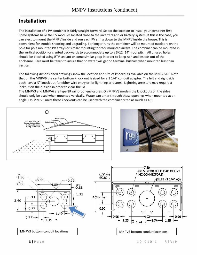
Installation The installation of a PV combiner is fairly straight forward. Select the location to install your combiner first. Some systems have the PV modules located close to the inverters and or battery system. If this is the case, you can elect to mount the MNPV inside and run each PV string down to the MNPV inside the house. This is convenient for trouble shooting and upgrading. For longer runs the combiner will be mounted outdoors on the pole for pole mounted PV arrays or similar mounting for rack mounted arrays. The combiner can be mounted in the vertical position or slanted backwards to accommodate up to a 3/12 (14°) roof pitch. All unused holes should be blocked using RTV sealant or some similar goop in order to keep rain and insects out of the enclosure. Care must be taken to insure that no water will get on terminal busbars when mounted less than vertical. The following dimensioned drawings show the location and size of knockouts available on the MNPV3&6. Note that on the MNPV6 the center bottom knock out is sized for a 1 1/4” conduit adapter. The left and right side each have a ½” knock out for either wire entry or for lightning arrestors. Lightning arrestors may require a locknut on the outside in order to clear the lid. The MNPV3 and MNPV6 are type 3R rainproof enclosures. On MNPV3 models the knockouts on the sides should only be used when mounted vertically. Water can enter through these openings when mounted at an angle. On MNPV6 units these knockouts can be used with the combiner tilted as much as 45°.
MNPV3 bottom conduit locations MNPV6 bottom conduit locations

MNPV Instructions (continued)
4 | P a g e 1 0 - 0 1 0 - 1 R E V : H
Note: The plastic dead front fits very tight. You must first remove the lid in order to remove the deadfront. Remove the deadfront: Pry off the lid as shown using something like a screwdriver as a lever. The dead front will then come out easily. MNPV6 shown with breakers & MNSPD Surge Suppressor MNPV3 with 3 breakers The MNPV6 enclosure can be split into two sections making it equivalent to 2 MNPV3 combiners in one. This is sometimes done in 12 and 24V systems where more controllers are required for additional power. For instance in a 24 volt system using a 60 amp charge controller, you are limited to about 1600 watts of PV per controller. If using Kyocera KC130 modules, you can make three strings of 4 modules in series. This adds up to 1560 watts per controller. That is a good match of PV vs. controller capability. The MNPV3 can accommodate this arrangement directly, but the MNPV6 can accommodate two of these systems, thus saving wiring, space and money. See the following figure on splitting the busbar into two systems.
Torque –Fuseholder / Circuit Breaker QY Circuit breakers 20 in-lbs (2.3Nm) USM1 Fuseholders 15 in-lbs (1.7Nm)
Torque – Terminal Bus Bar
10AWG 20 in-lbs (2.3Nm) 8AWG 25 in-lbs (2.8Nm) 6AWG 35 in-lbs (4.0Nm) 4AWG 45 in-lbs (5.1Nm) 2AWG – 1/0 50 in-lbs (5.6Nm)
MNPV Instructions (continued)
5 | P a g e 1 0 - 0 1 0 - 1 R E V : H
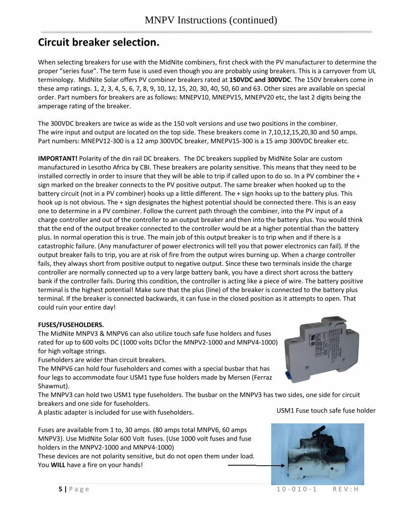
Circuit breaker selection. When selecting breakers for use with the MidNite combiners, first check with the PV manufacturer to determine the proper “series fuse”. The term fuse is used even though you are probably using breakers. This is a carryover from UL terminology. MidNite Solar offers PV combiner breakers rated at 150VDC and 300VDC. The 150V breakers come in these amp ratings. 1, 2, 3, 4, 5, 6, 7, 8, 9, 10, 12, 15, 20, 30, 40, 50, 60 and 63. Other sizes are available on special order. Part numbers for breakers are as follows: MNEPV10, MNEPV15, MNEPV20 etc, the last 2 digits being the amperage rating of the breaker. The 300VDC breakers are twice as wide as the 150 volt versions and use two positions in the combiner. The wire input and output are located on the top side. These breakers come in 7,10,12,15,20,30 and 50 amps. Part numbers: MNEPV12-300 is a 12 amp 300VDC breaker, MNEPV15-300 is a 15 amp 300VDC breaker etc. IMPORTANT! Polarity of the din rail DC breakers. The DC breakers supplied by MidNite Solar are custom manufactured in Lesotho Africa by CBI. These breakers are polarity sensitive. This means that they need to be installed correctly in order to insure that they will be able to trip if called upon to do so. In a PV combiner the + sign marked on the breaker connects to the PV positive output. The same breaker when hooked up to the battery circuit (not in a PV combiner) hooks up a little different. The + sign hooks up to the battery plus. This hook up is not obvious. The + sign designates the highest potential should be connected there. This is an easy one to determine in a PV combiner. Follow the current path through the combiner, into the PV input of a charge controller and out of the controller to an output breaker and then into the battery plus. You would think that the end of the output breaker connected to the controller would be at a higher potential than the battery plus. In normal operation this is true. The main job of this output breaker is to trip when and if there is a catastrophic failure. (Any manufacturer of power electronics will tell you that power electronics can fail). If the output breaker fails to trip, you are at risk of fire from the output wires burning up. When a charge controller fails, they always short from positive output to negative output. Since these two terminals inside the charge controller are normally connected up to a very large battery bank, you have a direct short across the battery bank if the controller fails. During this condition, the controller is acting like a piece of wire. The battery positive terminal is the highest potential! Make sure that the plus (line) of the breaker is connected to the battery plus terminal. If the breaker is connected backwards, it can fuse in the closed position as it attempts to open. That could ruin your entire day! FUSES/FUSEHOLDERS. The MidNite MNPV3 & MNPV6 can also utilize touch safe fuse holders and fuses rated for up to 600 volts DC (1000 volts DCfor the MNPV2-1000 and MNPV4-1000) for high voltage strings. Fuseholders are wider than circuit breakers. The MNPV6 can hold four fuseholders and comes with a special busbar that has four legs to accommodate four USM1 type fuse holders made by Mersen (Ferraz Shawmut). The MNPV3 can hold two USM1 type fuseholders. The busbar on the MNPV3 has two sides, one side for circuit breakers and one side for fuseholders. A plastic adapter is included for use with fuseholders. Fuses are available from 1 to, 30 amps. (80 amps total MNPV6, 60 amps MNPV3). Use MidNite Solar 600 Volt fuses. (Use 1000 volt fuses and fuse holders in the MNPV2-1000 and MNPV4-1000) These devices are not polarity sensitive, but do not open them under load. You WILL have a fire on your hands!
USM1 Fuse touch safe fuse holder
MNPV Instructions (continued)
6 | P a g e 1 0 - 0 1 0 - 1 R E V : H
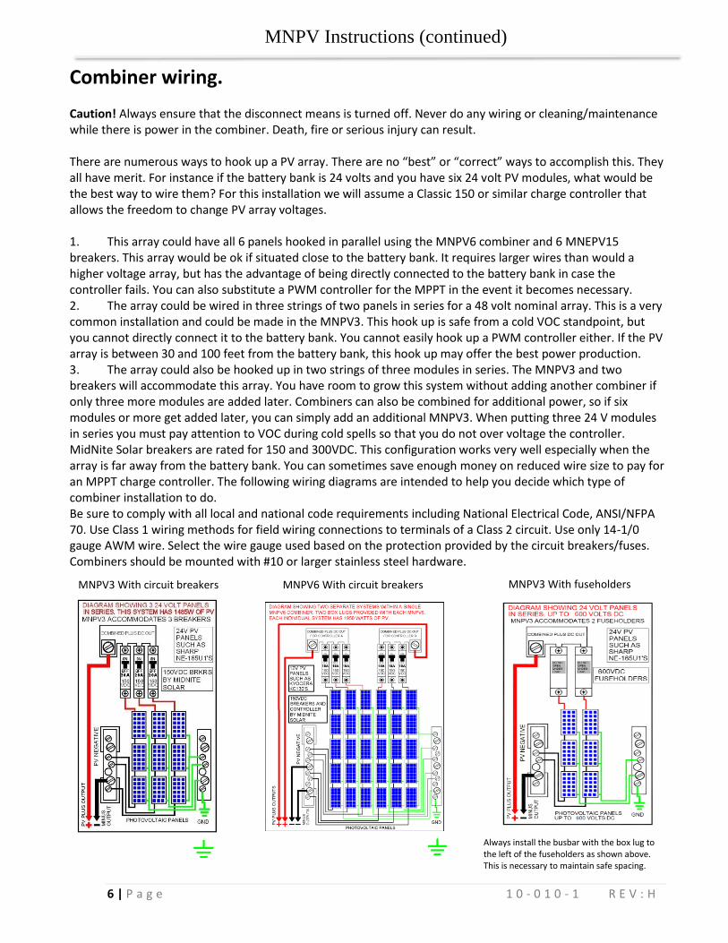
Combiner wiring. Caution! Always ensure that the disconnect means is turned off. Never do any wiring or cleaning/maintenance while there is power in the combiner. Death, fire or serious injury can result. There are numerous ways to hook up a PV array. There are no “best” or “correct” ways to accomplish this. They all have merit. For instance if the battery bank is 24 volts and you have six 24 volt PV modules, what would be the best way to wire them? For this installation we will assume a Classic 150 or similar charge controller that allows the freedom to change PV array voltages. 1. This array could have all 6 panels hooked in parallel using the MNPV6 combiner and 6 MNEPV15 breakers. This array would be ok if situated close to the battery bank. It requires larger wires than would a higher voltage array, but has the advantage of being directly connected to the battery bank in case the controller fails. You can also substitute a PWM controller for the MPPT in the event it becomes necessary. 2. The array could be wired in three strings of two panels in series for a 48 volt nominal array. This is a very common installation and could be made in the MNPV3. This hook up is safe from a cold VOC standpoint, but you cannot directly connect it to the battery bank. You cannot easily hook up a PWM controller either. If the PV array is between 30 and 100 feet from the battery bank, this hook up may offer the best power production. 3. The array could also be hooked up in two strings of three modules in series. The MNPV3 and two breakers will accommodate this array. You have room to grow this system without adding another combiner if only three more modules are added later. Combiners can also be combined for additional power, so if six modules or more get added later, you can simply add an additional MNPV3. When putting three 24 V modules in series you must pay attention to VOC during cold spells so that you do not over voltage the controller. MidNite Solar breakers are rated for 150 and 300VDC. This configuration works very well especially when the array is far away from the battery bank. You can sometimes save enough money on reduced wire size to pay for an MPPT charge controller. The following wiring diagrams are intended to help you decide which type of combiner installation to do. Be sure to comply with all local and national code requirements including National Electrical Code, ANSI/NFPA 70. Use Class 1 wiring methods for field wiring connections to terminals of a Class 2 circuit. Use only 14-1/0 gauge AWM wire. Select the wire gauge used based on the protection provided by the circuit breakers/fuses. Combiners should be mounted with #10 or larger stainless steel hardware.
MNPV3 With circuit breakers
MNPV3 With fuseholders MNPV6 With circuit breakers
Always install the busbar with the box lug to the left of the fuseholders as shown above. This is necessary to maintain safe spacing.
MNPV Instructions (continued)
7 | P a g e 1 0 - 0 1 0 - 1 R E V : H
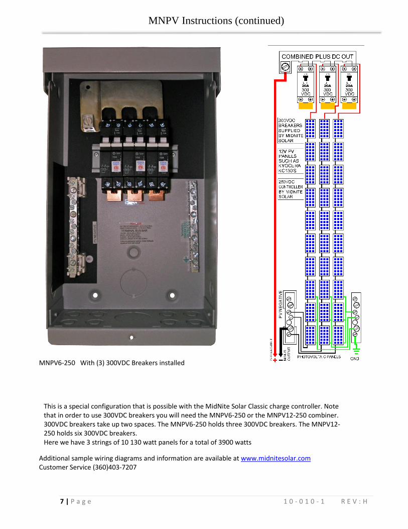
This is a special configuration that is possible with the MidNite Solar Classic charge controller. Note that in order to use 300VDC breakers you will need the MNPV6-250 or the MNPV12-250 combiner. 300VDC breakers take up two spaces. The MNPV6-250 holds three 300VDC breakers. The MNPV12-250 holds six 300VDC breakers. Here we have 3 strings of 10 130 watt panels for a total of 3900 watts
MNPV6-250 With (3) 300VDC Breakers installed
Additional sample wiring diagrams and information are available at www.midnitesolar.com Customer Service (360)403-7207
MNPV Instructions (continued)
8 | P a g e 1 0 - 0 1 0 - 1 R E V : H
Typical install.
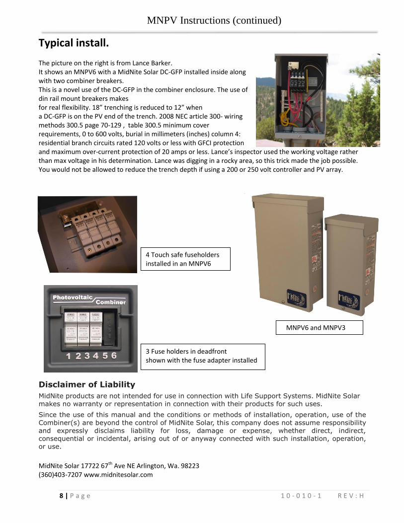
The picture on the right is from Lance Barker. It shows an MNPV6 with a MidNite Solar DC-GFP installed inside along with two combiner breakers. This is a novel use of the DC-GFP in the combiner enclosure. The use of din rail mount breakers makes for real flexibility. 18” trenching is reduced to 12” when a DC-GFP is on the PV end of the trench. 2008 NEC article 300- wiring methods 300.5 page 70-129 , table 300.5 minimum cover requirements, 0 to 600 volts, burial in millimeters (inches) column 4: residential branch circuits rated 120 volts or less with GFCI protection and maximum over-current protection of 20 amps or less. Lance’s inspector used the working voltage rather than max voltage in his determination. Lance was digging in a rocky area, so this trick made the job possible. You would not be allowed to reduce the trench depth if using a 200 or 250 volt controller and PV array.
Disclaimer of Liability
MidNite products are not intended for use in connection with Life Support Systems. MidNite Solar makes no warranty or representation in connection with their products for such uses.
Since the use of this manual and the conditions or methods of installation, operation, use of the
Combiner(s) are beyond the control of MidNite Solar, this company does not assume responsibility and expressly disclaims liability for loss, damage or expense, whether direct, indirect, consequential or incidental, arising out of or anyway connected with such installation, operation, or use.
MidNite Solar 17722 67th Ave NE Arlington, Wa. 98223 (360)403-7207 www.midnitesolar.com
MNPV6 and MNPV3
3 Fuse holders in deadfront shown with the fuse adapter installed
4 Touch safe fuseholders installed in an MNPV6