Embed Size (px)
Citation preview

Includes INTELLICODE® 2 Remote Control. Safe-T-Beam® System must be installed to close door.For use only with residential sectional or one piece overhead garage doors.
Homelink® and Car2U® compatible.
For Answers and Assistance:1.800.354.3643
or visit www.geniepro.com
SAVE THIS MANUAL FOR FUTURE REFERENCE. INSTALLER: LEAVE THIS MANUAL WITH HOMEOWNER.
IntelliG™ 1000Model 3024
GARAGE DOOR OPENER
Homelink® is a registered trademark of Johnson Controls Technology Company. Car2U® is a registered trademark of Lear Corporation. © 2010 The Genie Company PN# 37066500118, 01/27/2010
©2010 The Genie Company 01/27/20102
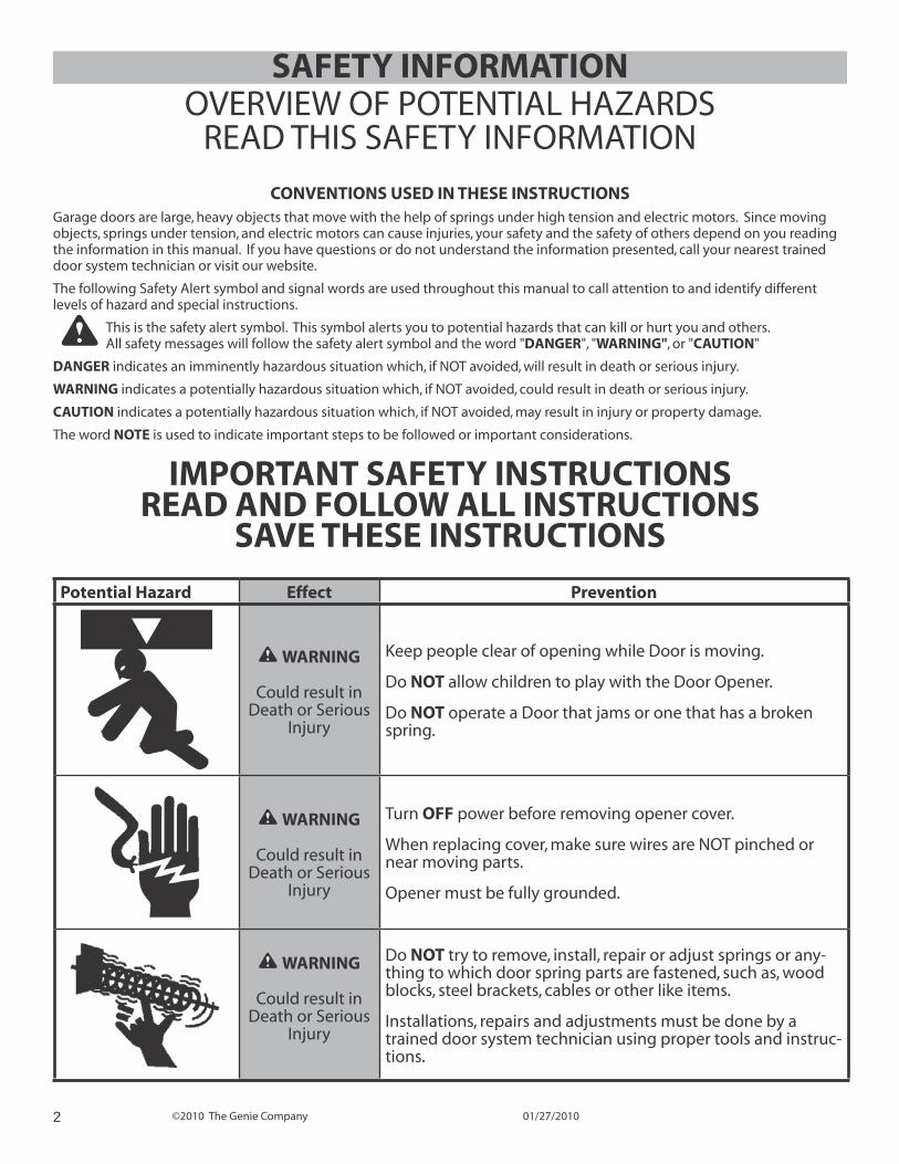
SAFETY INFORMATION
IMPORTANT SAFETY INSTRUCTIONSREAD AND FOLLOW ALL INSTRUCTIONS
SAVE THESE INSTRUCTIONS
CONVENTIONS USED IN THESE INSTRUCTIONSGarage doors are large, heavy objects that move with the help of springs under high tension and electric motors. Since moving objects, springs under tension, and electric motors can cause injuries, your safety and the safety of others depend on you reading the information in this manual. If you have questions or do not understand the information presented, call your nearest trained door system technician or visit our website.
The following Safety Alert symbol and signal words are used throughout this manual to call attention to and identify different levels of hazard and special instructions.
This is the safety alert symbol. This symbol alerts you to potential hazards that can kill or hurt you and others. All safety messages will follow the safety alert symbol and the word "DANGER", "WARNING", or "CAUTION"
DANGER indicates an imminently hazardous situation which, if NOT avoided, will result in death or serious injury.
WARNING indicates a potentially hazardous situation which, if NOT avoided, could result in death or serious injury.
CAUTION indicates a potentially hazardous situation which, if NOT avoided, may result in injury or property damage.
The word NOTE is used to indicate important steps to be followed or important considerations.
Potential Hazard Effect Prevention
WARNING
Could result in Death or Serious
Injury
Keep people clear of opening while Door is moving.
Do NOT allow children to play with the Door Opener.
Do NOT operate a Door that jams or one that has a broken spring.
WARNING
Could result in Death or Serious
Injury
Turn OFF power before removing opener cover.
When replacing cover, make sure wires are NOT pinched or near moving parts.
Opener must be fully grounded.
WARNING
Could result in Death or Serious
Injury
Do NOT try to remove, install, repair or adjust springs or any-thing to which door spring parts are fastened, such as, wood blocks, steel brackets, cables or other like items.
Installations, repairs and adjustments must be done by a trained door system technician using proper tools and instruc-tions.
OVERVIEW OF POTENTIAL HAZARDSREAD THIS SAFETY INFORMATION
©2010 The Genie Company 01/27/2010 3
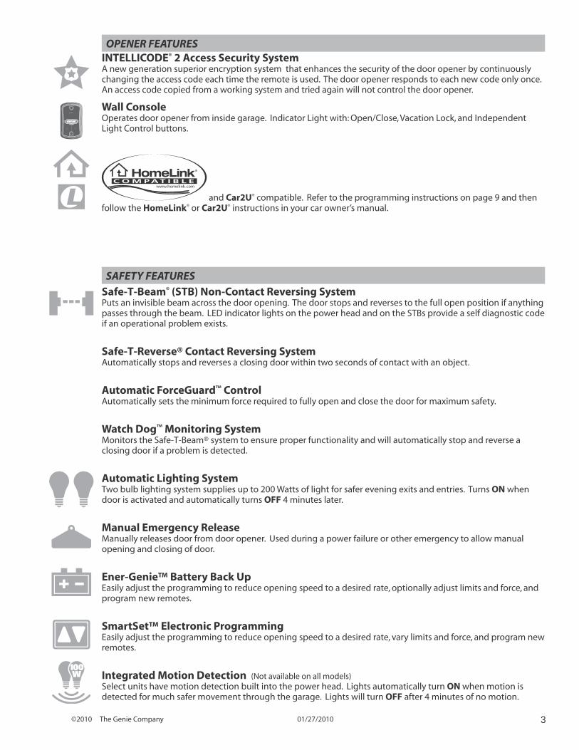
INTELLICODE® 2 Access Security SystemA new generation superior encryption system that enhances the security of the door opener by continuously changing the access code each time the remote is used. The door opener responds to each new code only once. An access code copied from a working system and tried again will not control the door opener.
OPENER FEATURES
Wall ConsoleOperates door opener from inside garage. Indicator Light with: Open/Close, Vacation Lock, and Independent Light Control buttons.
and Car2U® compatible. Refer to the programming instructions on page 9 and then follow the HomeLink® or Car2U® instructions in your car owner’s manual.
SAFETY FEATURESSafe-T-Beam® (STB) Non-Contact Reversing SystemPuts an invisible beam across the door opening. The door stops and reverses to the full open position if anything passes through the beam. LED indicator lights on the power head and on the STBs provide a self diagnostic code if an operational problem exists.
Safe-T-Reverse® Contact Reversing SystemAutomatically stops and reverses a closing door within two seconds of contact with an object.
Automatic ForceGuard™ ControlAutomatically sets the minimum force required to fully open and close the door for maximum safety.
Watch Dog™ Monitoring SystemMonitors the Safe-T-Beam® system to ensure proper functionality and will automatically stop and reverse a closing door if a problem is detected.
Automatic Lighting SystemTwo bulb lighting system supplies up to 200 Watts of light for safer evening exits and entries. Turns ON when door is activated and automatically turns OFF 4 minutes later.
Manual Emergency ReleaseManually releases door from door opener. Used during a power failure or other emergency to allow manual opening and closing of door.
Ener-Genie™ Battery Back UpEasily adjust the programming to reduce opening speed to a desired rate, optionally adjust limits and force, and program new remotes.
SmartSet™ Electronic ProgrammingEasily adjust the programming to reduce opening speed to a desired rate, vary limits and force, and program new remotes.
Integrated Motion Detection (Not available on all models)Select units have motion detection built into the power head. Lights automatically turn ON when motion is detected for much safer movement through the garage. Lights will turn OFF after 4 minutes of no motion.
©2010 The Genie Company 01/27/20104
TABLE OF CONTENTSSection ....................................................................................Page
Safety Information .................................................................................................... 2Opener Features & Safety Features ................................................................... 3Table of Contents ....................................................................................................... 4
Installation Important Installation Instructions ........................................................51 Programming Limits & Force .............................................................6-72 Program IntelliCode® 2 Remote to Power Head ..........................8
Programming HomeLink®, Car2U®, IntelliCode® 1 remotes or wireless keypads .................................................................................................................. 9
Reference 3 Typical Installed Illustrations ................................................................ 10-12
Typical Sectional Door Installation ............................................................10Typical One Piece Door Installation ...........................................................11Power Head & Rail Assembled View ...........................................................12
4 Overview of Power Head Controls .............................................................135 Overview of Remotes and Options ...................................................... 14-16
Panic Button .......................................................................................................14IntelliCode® Features ........................................................................................15Previously Installed Openers ..........................................................................1Lost or Stolen Remote - Clearing Memory ..................................................16
6 Maintenance & Troubleshooting ......................................................... 17-25 Important Safety Instructions ........................................................................17Routine Monthly Maintenance .....................................................................17Door Balance (Spring Tension) ......................................................................17Safe-T-Beam® System Check ..........................................................................17Contact Reverse Test .........................................................................................18Motion Detector - Overview ...........................................................................18Reset - Open/Close Travel Limit .....................................................................18Carriage Engage/Disengage ..........................................................................18Wall Console - Overview ..................................................................................19Change Light Bulbs ...........................................................................................19Optional Dual Wall Console - Installation .................................................19Chain or Belt Tension Adjustment ................................................................20Remote Battery Replacement ........................................................................20Wiring Diagram ................................................................................................21Speed Adjustment ............................................................................................22Force Adjustment ..............................................................................................23Troubleshooting Guide - Operation ..................................................... 24-25Troubleshooting Guide - Power Head LEDs ...............................................25
Warranty ......................................................................................................................26
PATENT STATEMENTPatents Pending
©2010 The Genie Company 01/27/2010 5
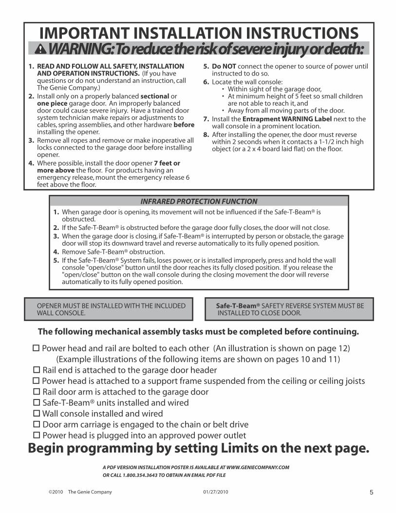
IMPORTANT INSTALLATION INSTRUCTIONS WARNING: To reduce the risk of severe injury or death:
1. READ AND FOLLOW ALL SAFETY, INSTALLATION AND OPERATION INSTRUCTIONS. (If you have questions or do not understand an instruction, call The Genie Company.)
2. Install only on a properly balanced sectional or one piece garage door. An improperly balanced door could cause severe injury. Have a trained door system technician make repairs or adjustments to cables, spring assemblies, and other hardware before installing the opener.
3. Remove all ropes and remove or make inoperative all locks connected to the garage door before installing opener.
4. Where possible, install the door opener 7 feet or more above the floor. For products having an emergency release, mount the emergency release 6 feet above the floor.
5. Do NOT connect the opener to source of power until instructed to do so.
6. Locate the wall console:• Within sight of the garage door,• At minimum height of 5 feet so small children
are not able to reach it, and• Away from all moving parts of the door.
7. Install the Entrapment WARNING Label next to the wall console in a prominent location.
8. After installing the opener, the door must reverse within 2 seconds when it contacts a 1-1/2 inch high object (or a 2 x 4 board laid flat) on the floor.
OPENER MUST BE INSTALLED WITH THE INCLUDED WALL CONSOLE.
Safe-T-Beam® SAFETY REVERSE SYSTEM MUST BE INSTALLED TO CLOSE DOOR.
INFRARED PROTECTION FUNCTION1. When garage door is opening, its movement will not be influenced if the Safe-T-Beam® is
obstructed.2. If the Safe-T-Beam® is obstructed before the garage door fully closes, the door will not close.3. When the garage door is closing, if Safe-T-Beam® is interrupted by person or obstacle, the garage
door will stop its downward travel and reverse automatically to its fully opened position.4. Remove Safe-T-Beam® obstruction.5. If the Safe-T-Beam® System fails, loses power, or is installed improperly, press and hold the wall
console "open/close" button until the door reaches its fully closed position. If you release the "open/close" button on the wall console during the closing movement the door will reverse automatically to its fully opened position.
A PDF VERSION INSTALLATION POSTER IS AVAILABLE AT WWW.GENIECOMPANY.COM
OR CALL 1.800.354.3643 TO OBTAIN AN EMAIL PDF FILE
The following mechanical assembly tasks must be completed before continuing.
Power head and rail are bolted to each other (An illustration is shown on page 12)(Example illustrations of the following items are shown on pages 10 and 11)
Rail end is attached to the garage door header Power head is attached to a support frame suspended from the ceiling or ceiling joists Rail door arm is attached to the garage door Safe-T-Beam® units installed and wired Wall console installed and wired Door arm carriage is engaged to the chain or belt drive Power head is plugged into an approved power outlet
Begin programming by setting Limits on the next page.
©2010 The Genie Company 01/27/20106
PROGRAM
SET
—
+ 5 SE
CS
SET
TIN
G &
TES
TIN
G L
IMIT
S A
ND
FO
RC
E
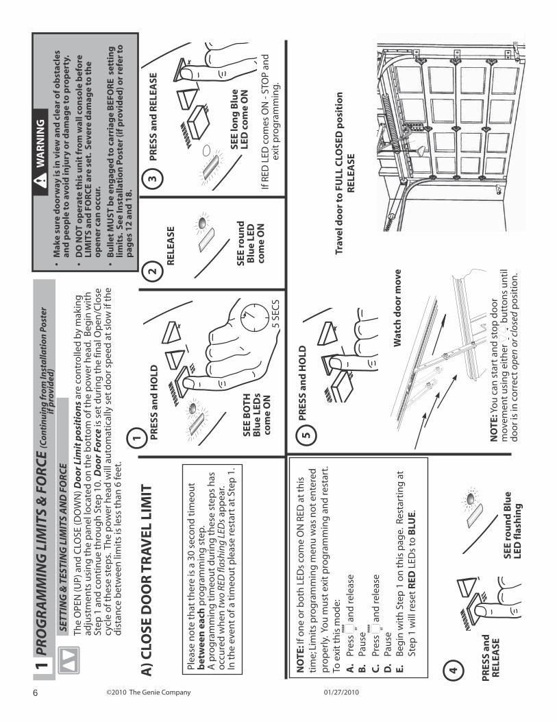
The
OPE
N (U
P) a
nd
CLO
SE (D
OW
N) D
oo
r Li
mit
po
siti
on
s ar
e co
ntr
olle
d b
y m
akin
g
adju
stm
ents
usi
ng
th
e p
anel
loca
ted
on
th
e b
ott
om
of t
he
po
wer
hea
d.
Beg
in w
ith
St
ep 1
an
d c
on
tin
ue
thro
ug
h S
tep
10.
Do
or
Forc
e is
set
du
rin
g t
he
final
Op
en/C
lose
cy
cle
of t
hes
e st
eps.
Th
e p
ow
er h
ead
will
au
tom
atic
ally
set
do
or s
pee
d a
t sl
ow
if t
he
dis
tan
ce b
etw
een
lim
its
is le
ss t
han
6 fe
et.
A) C
LOSE
DO
OR
TR
AV
EL L
IMIT
NO
TE: Y
ou
can
sta
rt a
nd
sto
p d
oo
r m
ovem
ent
usi
ng
eit
her
bu
tto
ns
un
til
do
or i
s in
co
rrec
t op
en o
r clo
sed
po
siti
on
.
Wat
ch d
oo
r m
ove
PR
OG
RA
MM
ING
LIM
ITS
& F
OR
CE
(Co
nti
nu
ing
fro
m In
sta
llati
on
Po
ster
if p
rovi
ded
)1
GRAM
SE
—
+
PR
ESS
and
HO
LD5
PROGRAM
SET
—
+
PR
ESS
and
HO
LD
SEE
BO
TH
Blu
e LE
Ds
com
e O
N
SEE
rou
nd
B
lue
LED
co
me
ON
PROGRAM
SET
—
SEE
rou
nd
Blu
e LE
D fl
ash
ing
REL
EASE
12
3
4NO
TE: I
f on
e o
r bo
th L
EDs
com
e O
N R
ED a
t th
is
tim
e; L
imit
s p
rog
ram
min
g m
enu
was
no
t en
tere
d
pro
per
ly. Y
ou
mu
st e
xit
pro
gra
mm
ing
an
d re
star
t.
To e
xit
this
mo
de:
A.
Pres
s PROGRAM
SET a
nd
rele
ase
B.
Pau
se
C.
Pres
s PROGRAM
SET a
nd
rele
ase
D.
Pau
seE.
B
egin
wit
h S
tep
1 o
n t
his
pag
e. R
esta
rtin
g a
t St
ep 1
will
rese
t R
ED L
EDs
to B
LUE.
PR
ESS
and
REL
EASE
WA
RN
ING
• M
ake
sure
do
orw
ay is
in v
iew
an
d c
lear
of o
bst
acle
s an
d p
eop
le t
o a
void
inju
ry o
r d
amag
e to
pro
per
ty.
• D
O N
OT
op
erat
e th
is u
nit
fro
m w
all c
on
sole
bef
ore
LI
MIT
S an
d F
OR
CE
are
set.
Sev
ere
dam
age
to t
he
op
ener
can
occ
ur.
• B
ulle
t M
UST
be
eng
aged
to
car
riag
e B
EFO
RE
set
tin
g
limit
s. S
ee In
stal
lati
on
Po
ster
(if p
rovi
ded
) or
refe
r to
p
ages
12
an
d 1
8.
Plea
se n
ote
th
at t
her
e is
a 3
0 se
con
d t
imeo
ut
bet
wee
n e
ach
pro
gra
mm
ing
ste
p.
A p
rog
ram
min
g t
imeo
ut
du
rin
g t
hes
e st
eps
has
o
ccu
red
wh
en tw
o RE
D fl
ashi
ng L
EDs
app
ear.
In
th
e ev
ent
of a
tim
eou
t p
leas
e re
star
t at
Ste
p 1
.
NO
TC
E O
R C
M
UCD
U O
N N H
D
Trav
el d
oo
r to
FU
LL C
LOSE
D p
osi
tio
nR
ELEA
SE
PR
ESS
and
R
ELEA
SE
SEE
lon
g B
lue
LED
co
me
ON
If RE
D L
ED c
om
es O
N -
STO
P an
d
exit
pro
gra
mm
ing.
©2010 The Genie Company 01/27/2010 7
PROGRAM
SET
—
PR
ESS
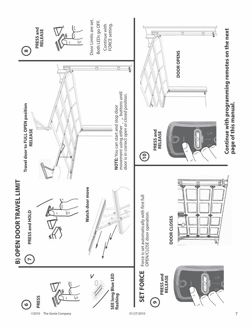
SEE
lon
g B
lue
LED
fl
ash
ing
6
Wat
ch d
oo
r m
ove
RAM
SET
—
+
B) O
PEN
DO
OR
TR
AV
EL L
IMIT
NO
TE
OR
M O
RC
D O
W O
AD
DO
OR
CLO
SES
DO
OR
OP
ENSDo
or L
imit
s ar
e se
t.
Bo
th L
EDs
go
OFF
.
Co
nti
nu
e w
ith
FO
RCE
sett
ing.
SET
FOR
CE
Forc
e is
set
au
tom
atic
ally
wit
h fi
rst
full
OPE
N/C
LOSE
do
or o
per
atio
n.
78
9
10 C
on
tin
ue
wit
h p
rog
ram
min
g r
emo
tes
on
th
e n
ext
pag
e o
f th
is m
anu
al.
PR
ESS
and
R
ELEA
SE
PR
ESS
and
HO
LD
PR
ESS
and
R
ELEA
SEP
RES
S an
d
REL
EASE
PROGRAM
SET
—Tr
avel
do
or
to F
ULL
OP
EN p
osi
tio
nR
ELEA
SE
NO
TE: Y
ou
can
sta
rt a
nd
sto
p d
oo
r m
ovem
ent
usi
ng
eit
her
bu
tto
ns
un
til
do
or i
s in
co
rrec
t op
en o
r clo
sed
po
siti
on
.
©2010 The Genie Company 01/27/20108
PROGRAM
SET
—
+ 5 SE
CS
PROGRAM
SET
—
+
PR
OG
RA
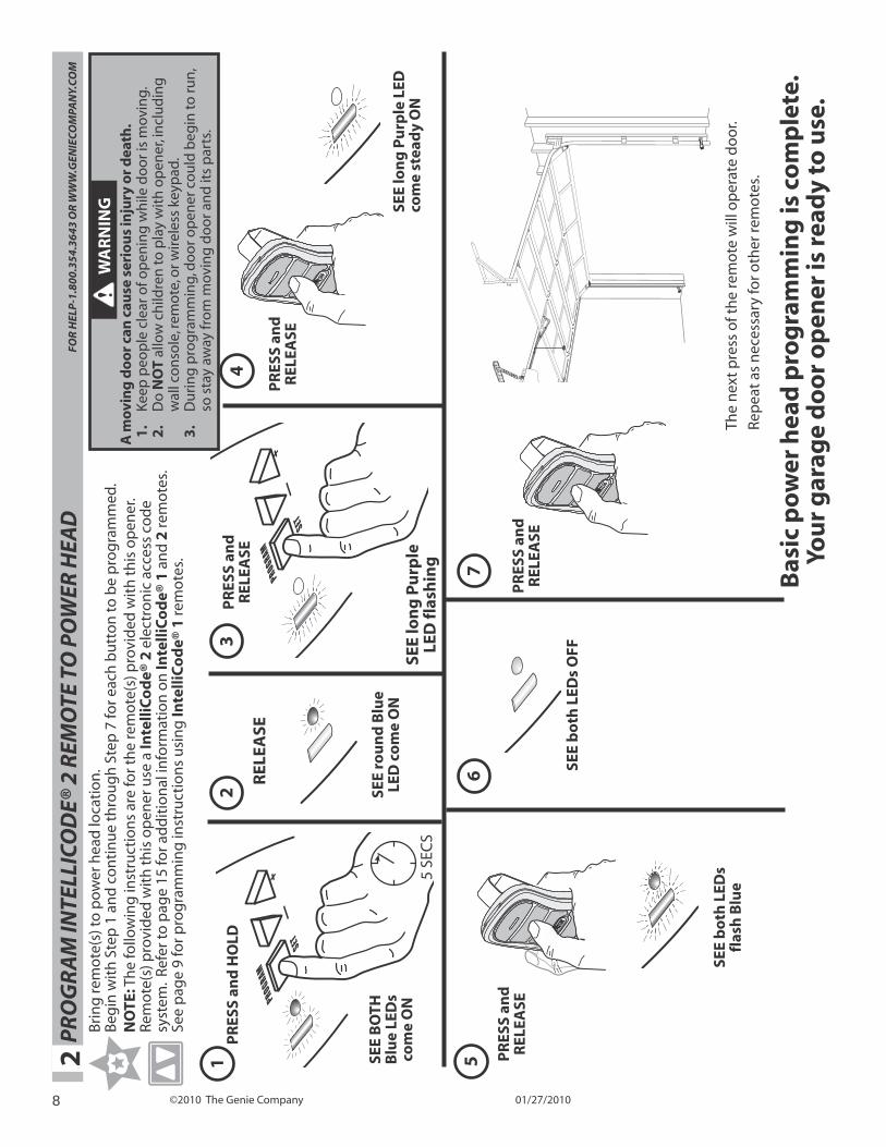
M IN
TELL
ICO
DE®
2 R
EMO
TE T
O P
OW
ER H
EAD
FO
R H
ELP
-1.8
00.3
54.3
643
OR
WW
W.G
ENIE
CO
MPA
NY.
CO
M2
PR
ESS
and
HO
LD
SEE
BO
TH
Blu
e LE
Ds
com
e O
N
SEE
rou
nd
Blu
e LE
D c
om
e O
NSE
E lo
ng
Pu
rple
LE
D fl
ash
ing
SEE
lon
g P
urp
le L
ED
com
e st
ead
y O
N
REL
EASE
12
34
56
7
The
nex
t p
ress
of t
he
rem
ote
will
op
erat
e d
oo
r.
Rep
eat
as n
eces
sary
for o
ther
rem
ote
s.
Bri
ng
rem
ote
(s) t
o p
ow
er h
ead
loca
tio
n.
Beg
in w
ith
Ste
p 1
an
d c
on
tin
ue
thro
ug
h S
tep
7 fo
r eac
h b
utt
on
to b
e p
rog
ram
med
.N
OTE
: Th
e fo
llow
ing
inst
ruct
ion
s ar
e fo
r th
e re
mo
te(s
) pro
vid
ed w
ith
th
is o
pen
er.
Rem
ote
(s) p
rovi
ded
wit
h t
his
op
ener
use
a In
telli
Co
de®
2 e
lect
ron
ic a
cces
s co
de
syst
em.
Refe
r to
pag
e 15
for a
dd
itio
nal
info
rmat
ion
on
Inte
lliC
od
e® 1
an
d 2
rem
ote
s.
See
pag
e 9
for p
rog
ram
min
g in
stru
ctio
ns
usi
ng
Inte
lliC
od
e® 1
rem
ote
s.
PR
ESS
and
R
ELEA
SE
PR
ESS
and
R
ELEA
SE
PR
ESS
and
R
ELEA
SE
Bas
ic p
ow
er h
ead
pro
gra
mm
ing
is c
om
ple
te.
You
r g
arag
e d
oo
r o
pen
er is
rea
dy
to u
se.
W
AR
NIN
G
A m
ovi
ng
do
or
can
cau
se s
erio
us
inju
ry o
r d
eath
.1
. K
eep
peo
ple
cle
ar o
f op
enin
g w
hile
do
or i
s m
ovin
g.2
. D
o N
OT
allo
w c
hild
ren
to p
lay
wit
h o
pen
er, i
ncl
ud
ing
w
all c
on
sole
, rem
ote
, or w
irel
ess
keyp
ad.
3.
Du
rin
g p
rog
ram
min
g, d
oo
r op
ener
co
uld
beg
in to
run
, so
sta
y aw
ay fr
om
mov
ing
do
or a
nd
its
par
ts.
SEE
bo
th L
EDs
OFF
SEE
bo
th L
EDs
flas
h B
lue
PR
ESS
and
R
ELEA
SE
©2010 The Genie Company 01/27/2010 9
PROGRAM
SET
—
+ 5 SE
CS
PROGRAM
SET
—
+
PR
ESS
and
HO
LD
SEE
BO
TH
Blu
e LE
Ds
com
e O
N
SEE
on
e B
lue
LED
co
me
ON
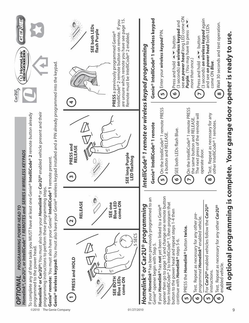
PR
ESS
a p
revi
ou
sly
pro
gra
mm
ed G
enie
® In
telli
Co
de®
2 re
mo
te b
utt
on
on
rem
ote
. If
you
ar
e u
nsu
re w
hic
h re
mo
te y
ou
hav
e se
e p
age
15.
Rem
ote
mu
st b
e In
telli
Co
de®
2 e
nab
led
.
REL
EASE
12
34
OP
TIO
NA
L
PR
OG
RA
MM
ING
PO
WER
HEA
D T
OH
om
elin
k®, C
ar2
U®,
or
Inte
lliC
od
e® 1
REM
OTE
S a
nd
SER
IES
II W
IREL
ESS
KEY
PAD
S
To c
om
ple
te a
ny
of t
hes
e ta
sks
you
MU
ST h
ave
at le
ast
on
e G
enie
® In
telli
Co
de®
2 re
mo
te b
utto
n al
read
y p
rog
ram
med
to t
he
po
wer
hea
d.
Ho
mel
ink®
or
Car
2U
®: Y
ou
mu
st a
lso
hav
e yo
ur H
om
elin
k® o
r Ca
r2U
® en
able
d v
ehic
le p
rese
nt
and
th
eir
pro
gra
mm
ing
inst
ruct
ion
s to
per
form
th
ese
pro
gra
mm
ing
ste
ps.
Gen
ie®
rem
ote
: Yo
u m
ust
als
o h
ave
you
r Gen
ie®
Inte
lliC
od
e® 1
rem
ote
pre
sen
t. G
enie
® w
irel
ess
keyp
ad: Y
ou
mu
st a
lso
hav
e yo
ur G
enie
® w
irel
ess
keyp
ad in
stal
led
an
d a
PIN
alr
ead
y p
rog
ram
med
into
th
e ke
ypad
.
PR
ESS
and
R
ELEA
SE
5O
n t
he
Inte
lliC
od
e® 1
rem
ote
PRE
SS
a b
utt
on
an
d R
ELEA
SE.
6SE
E b
oth
LED
s fla
sh B
lue.
Inte
lliC
od
e® 1
rem
ote
or
wir
eles
s ke
ypa
d p
rog
ram
min
g
7O
n t
he
Inte
lliC
od
e® 1
rem
ote
PRE
SS
the
sam
e b
utt
on
an
d R
ELEA
SE.
The
nex
t p
ress
of t
he
rem
ote
will
o
per
ate
do
or.
5En
ter y
ou
r wir
eles
s ke
ypa
d P
IN.
6Pr
ess
and
ho
ld
bu
tto
n
(3 s
eco
nd
s) o
n w
irel
ess
keyp
ad a
nd
se
e o
n p
ower
hea
d lo
ng
LED
co
me
ON
P
urp
le.
(Yo
u m
ay h
ave
to p
ress
mor
e th
an o
nce.
)
8Te
st.
Rep
eat
as n
eces
sary
for a
ny
oth
er In
telli
Co
de®
1 re
mo
tes.
7Pr
ess
and
ho
ld
bu
tto
n
(3 s
eco
nd
s) o
n w
irel
ess
keyp
ad
ag
ain
an
d s
ee o
n p
ower
hea
d b
oth
LED
s co
me
ON
Blu
e.
8W
ait
30 s
eco
nd
s an
d te
st o
per
atio
n.
Gen
ie®
Inte
lliC
od
e® 1
rem
ote
Gen
ie®
Inte
lliC
od
e® 1
wir
eles
s ke
ypad
SEE
lon
g P
urp
le
LED
flas
hin
g
SEE
bo
th L
EDs
flas
h P
urp
le
All
op
tio
nal
pro
gra
mm
ing
is c
om
ple
te.
You
r g
arag
e d
oo
r o
pen
er is
rea
dy
to u
se.
5Fo
r Ca
r2U
® en
able
d v
ehic
les
follo
w t
he
Ca
r2U
® in
stru
ctio
ns.
6Te
st.
Rep
eat
as n
eces
sary
for a
ny
oth
er C
ar2
U®
enab
led
veh
icle
.
Ho
mel
ink®
or
Car
2U
® p
rog
ram
min
gIf
you
r Ho
mel
ink®
has
bee
n p
revi
ou
sly
pro
gra
mm
ed to
an
G
enie
® o
pen
er b
egin
wit
h S
tep
5.
If yo
ur H
om
elin
k® h
as n
ot
yet b
een
lin
ked
to a
Gen
ie®
op
ener
then
go
to p
age
15 a
nd
ch
ang
e o
ne
rem
ote
bu
tto
n
fro
m In
telli
Co
de®
2 to
Inte
lliC
od
e® 1
, th
en p
rog
ram
that
b
utt
on
to th
e p
ower
hea
d a
nd
rep
eat s
tep
s 1-
4 th
en
con
tin
ue
wit
h H
om
elin
k® s
tep
s 5-
6.
5 6
PRES
S th
e H
om
elin
k® b
utt
on
tw
ice.
Test
. Re
pea
t as
nec
essa
ry fo
r an
y o
ther
pre
-pr
ogra
mm
ed H
om
elin
k® e
nab
led
veh
icle
.
©2010 The Genie Company 01/27/201010
NOTICE O R B C M S O S R C EDU L OW ON A D E
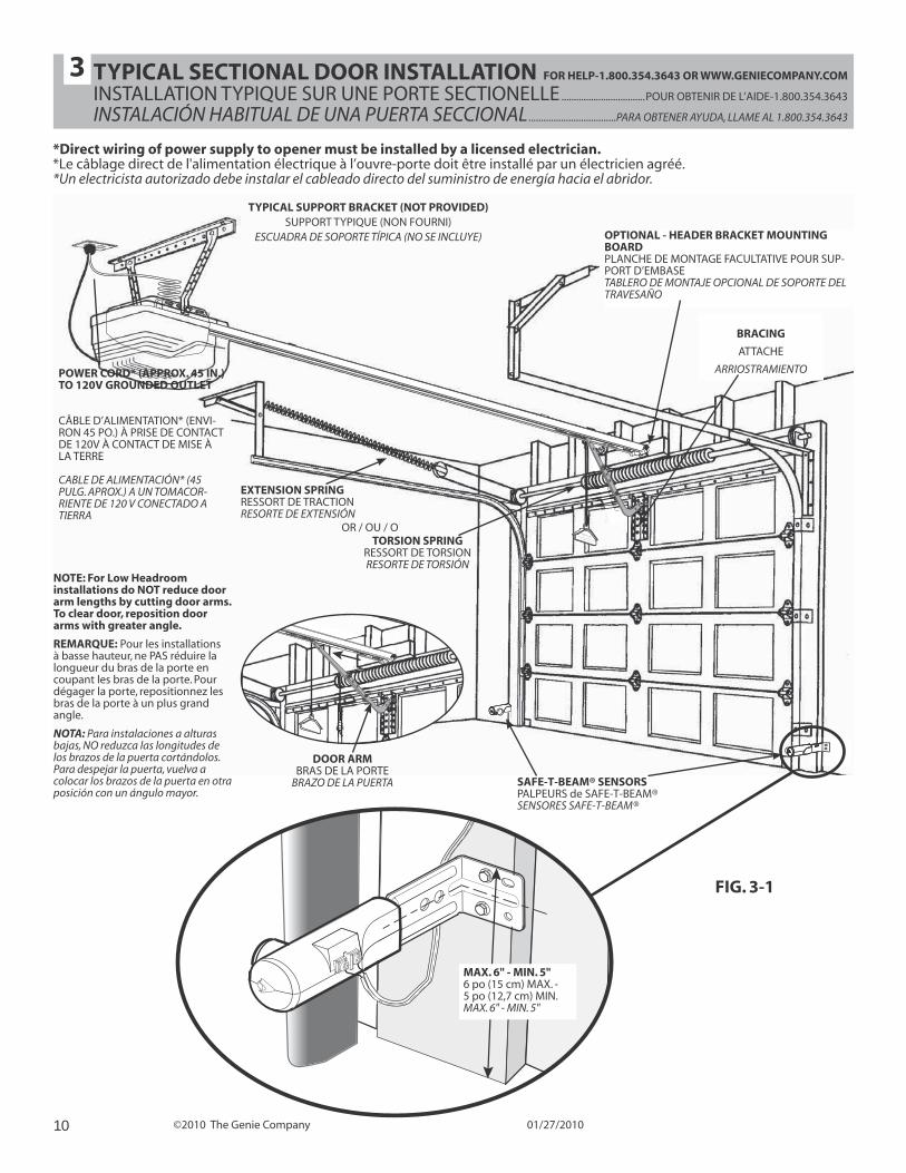
TYPICAL SECTIONAL DOOR INSTALLATION FOR HELP-1.800.354.3643 OR WWW.GENIECOMPANY.COM
INSTALLATION TYPIQUE SUR UNE PORTE SECTIONELLE ..................................POUR OBTENIR DE L’AIDE-1.800.354.3643
INSTALACIÓN HABITUAL DE UNA PUERTA SECCIONAL ...................................PARA OBTENER AYUDA, LLAME AL 1.800.354.3643
SAFE-T-BEAM® SENSORSPALPEURS de SAFE-T-BEAM® SENSORES SAFE-T-BEAM®
OPTIONAL - HEADER BRACKET MOUNTING BOARDPLANCHE DE MONTAGE FACULTATIVE POUR SUP-PORT D’EMBASE TABLERO DE MONTAJE OPCIONAL DE SOPORTE DEL TRAVESAÑO
BRACING
ATTACHE
ARRIOSTRAMIENTOPOWER CORD* (APPROX. 45 IN.) TO 120V GROUNDED OUTLET
CÂBLE D’ALIMENTATION* (ENVI-RON 45 PO.) À PRISE DE CONTACT DE 120V À CONTACT DE MISE À LA TERRE
CABLE DE ALIMENTACIÓN* (45 PULG. APROX.) A UN TOMACOR-RIENTE DE 120 V CONECTADO A TIERRA
EXTENSION SPRINGRESSORT DE TRACTION RESORTE DE EXTENSIÓN
TORSION SPRINGRESSORT DE TORSION RESORTE DE TORSIÓN
OR / OU / O
TYPICAL SUPPORT BRACKET (NOT PROVIDED) SUPPORT TYPIQUE (NON FOURNI)
ESCUADRA DE SOPORTE TÍPICA (NO SE INCLUYE)
*Direct wiring of power supply to opener must be installed by a licensed electrician.*Le câblage direct de l'alimentation électrique à l’ouvre-porte doit être installé par un électricien agréé.*Un electricista autorizado debe instalar el cableado directo del suministro de energía hacia el abridor.
3
FIG. 3-1
DOOR ARMBRAS DE LA PORTE
BRAZO DE LA PUERTA
NOTE: For Low Headroom installations do NOT reduce door arm lengths by cutting door arms. To clear door, reposition door arms with greater angle.
REMARQUE: Pour les installations à basse hauteur, ne PAS réduire la longueur du bras de la porte en coupant les bras de la porte. Pour dégager la porte, repositionnez les bras de la porte à un plus grand angle.
NOTA: Para instalaciones a alturas bajas, NO reduzca las longitudes de los brazos de la puerta cortándolos. Para despejar la puerta, vuelva a colocar los brazos de la puerta en otra posición con un ángulo mayor.
MAX. 6" - MIN. 5"6 po (15 cm) MAX. -5 po (12,7 cm) MIN.MAX. 6" - MIN. 5"
©2010 The Genie Company 01/27/2010 11
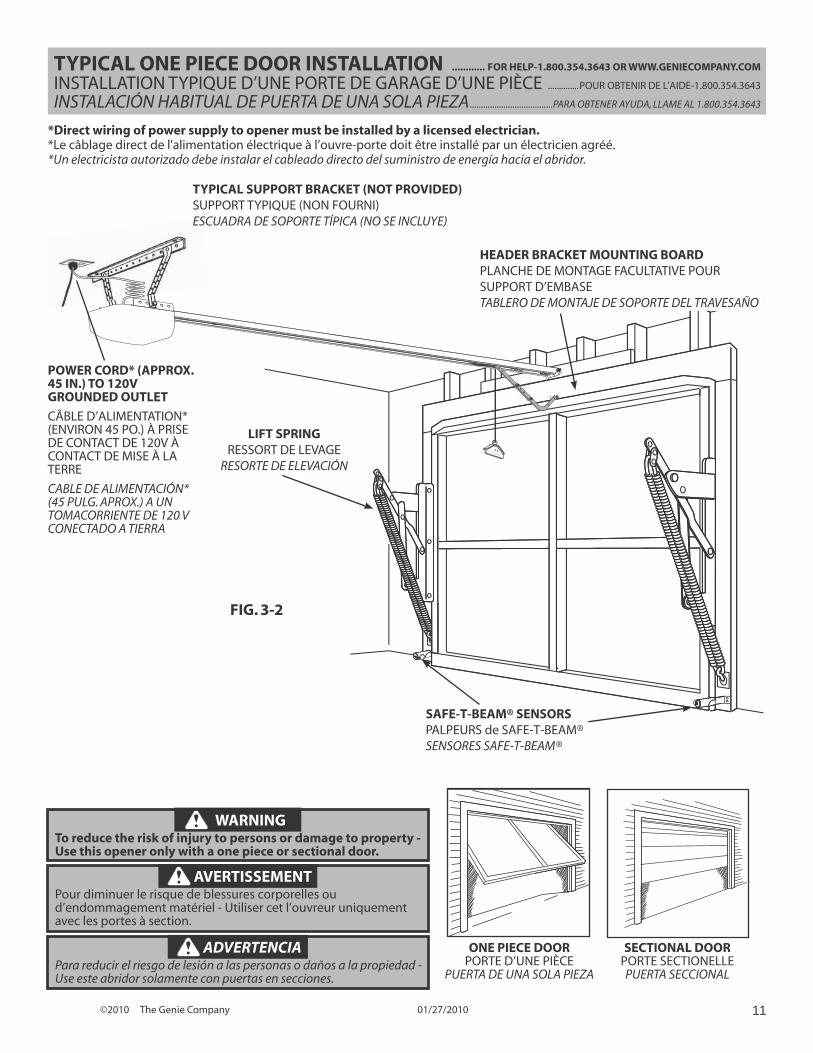
SECTIONAL DOORPORTE SECTIONELLEPUERTA SECCIONAL
ONE PIECE DOORPORTE D’UNE PIÈCE
PUERTA DE UNA SOLA PIEZA
O R E OM S BST U TEDU DO N O H N LE
LIFT SPRINGRESSORT DE LEVAGE
RESORTE DE ELEVACIÓN
*Direct wiring of power supply to opener must be installed by a licensed electrician.*Le câblage direct de l'alimentation électrique à l’ouvre-porte doit être installé par un électricien agréé.*Un electricista autorizado debe instalar el cableado directo del suministro de energía hacia el abridor.
TYPICAL ONE PIECE DOOR INSTALLATION ............ FOR HELP-1.800.354.3643 OR WWW.GENIECOMPANY.COM
INSTALLATION TYPIQUE D’UNE PORTE DE GARAGE D’UNE PIÈCE ..............POUR OBTENIR DE L’AIDE-1.800.354.3643
INSTALACIÓN HABITUAL DE PUERTA DE UNA SOLA PIEZA .....................................PARA OBTENER AYUDA, LLAME AL 1.800.354.3643
FIG. 3-2
WARNINGTo reduce the risk of injury to persons or damage to property - Use this opener only with a one piece or sectional door.
AVERTISSEMENTPour diminuer le risque de blessures corporelles ou d’endommagement matériel - Utiliser cet l’ouvreur uniquement avec les portes à section.
ADVERTENCIAPara reducir el riesgo de lesión a las personas o daños a la propiedad - Use este abridor solamente con puertas en secciones.
SAFE-T-BEAM® SENSORSPALPEURS de SAFE-T-BEAM® SENSORES SAFE-T-BEAM®
POWER CORD* (APPROX. 45 IN.) TO 120V GROUNDED OUTLET
CÂBLE D’ALIMENTATION* (ENVIRON 45 PO.) À PRISE DE CONTACT DE 120V À CONTACT DE MISE À LA TERRE
CABLE DE ALIMENTACIÓN* (45 PULG. APROX.) A UN TOMACORRIENTE DE 120 V CONECTADO A TIERRA
HEADER BRACKET MOUNTING BOARDPLANCHE DE MONTAGE FACULTATIVE POUR SUPPORT D’EMBASE TABLERO DE MONTAJE DE SOPORTE DEL TRAVESAÑO
TYPICAL SUPPORT BRACKET (NOT PROVIDED) SUPPORT TYPIQUE (NON FOURNI)ESCUADRA DE SOPORTE TÍPICA (NO SE INCLUYE)
©2010 The Genie Company 01/27/201012
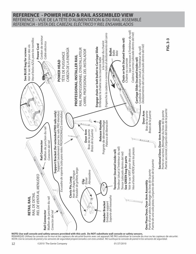
REFERENCE - POWER HEAD & RAIL ASSEMBLED VIEW RÉFÉRENCE – VUE DE LA TÊTE D’ALIMENTATION & DU RAIL ASSEMBLÉREFERENCIA - VISTA DEL CABEZAL ELÉCTRICO Y RIEL ENSAMBLADOS
NOTE: Use wall console and safety sensors provided with this unit. Do NOT substitute wall console or safety sensors.REMARQUE: Utilisez la console sur le mur et les capteurs de sécurité fournis avec cet appareil. NE PAS substituer la console du mur ou les capteurs de sécurité.NOTA: Use la consola de pared y los sensores de seguridad proporcionados con esta unidad. NO sustituya la consola de pared ni los sensores de seguridad.
FIG
. 3-3
Ten
sio
ner
(lo
cate
d in
sid
e ra
il)Te
nd
eur (
situ
é à
l'in
téri
eur d
u ra
il)
Tens
or (u
bica
do d
entr
o de
l rie
l)
Rel
ease
Han
dle
Poig
née
de
dév
erro
uill
age
Pala
nca
de li
bera
ción
PO
WER
HEA
DTÊ
TE D
E PU
ISSA
NC
EC
ABE
ZA D
E LA
EN
ERG
ÍA
Po
wer
Co
rdC
ord
on
de
sect
eur
Cab
le e
léct
rico
Do
or
Arm
Bra
s d
e la
po
rte
Braz
o de
la p
uert
a
On
e P
iece
Do
or,
Do
or
Arm
Ass
emb
lyPo
rte
d’u
ne
piè
ce, M
on
tag
e d
u b
ras
de
la p
ort
ePu
erta
de
una
sola
pie
za, C
onju
nto
del b
razo
de
la p
uert
a
Se
ctio
nal
Do
or,
Do
or
Arm
Ass
emb
lyPo
rte
en s
ecti
on
, Mo
nta
ge
du
bra
s d
e la
po
rte
Puer
ta s
ecci
onal
, Con
junt
o de
l bra
zo d
e la
pue
rta
Sup
po
rt B
rack
et (f
or
exte
nd
ed P
RO
rai
ls o
nly
)Su
pp
ort
(seu
lem
ent
po
ur l
es ra
ils P
RO é
ten
du
s)Es
cuad
ra d
e so
port
e (s
ólo
para
riel
es P
ROFE
SIO
NA
LES
exte
ndid
os)
Hea
der
Bra
cket
Emb
ase
sup
po
rtSo
port
e de
l tra
vesa
ñoCle
vis
Pin
, Lo
ng
A
xe d
e ch
ape,
lon
gu
ePa
sado
r de
grill
ete,
larg
o
Clip
Étri
erA
braz
ader
a
Eng
age
chai
n o
r b
elt
bu
llet
to C
arri
age
Slid
eEm
bra
yez
la c
haî
ne
ou
la c
ou
rro
ie b
alle
à
la c
ou
lisse
du
ch
ario
t
Enga
nche
la c
aden
a o
corr
ea b
ala
al d
esliz
amie
nto
del c
arro
Do
or
Arm
Bra
s d
e la
po
rte
Braz
o de
la p
uert
a
See
BLU
E b
ag fo
r sc
rew
sVo
ir le
sac
BLE
U p
ou
r des
vis
Vea
el b
olso
AZU
L pa
ra lo
s to
rnill
os
See
GR
EEN
bag
for
par
tsVo
ir le
sac
VER
T p
ou
r des
piè
ces
Vea
el b
olso
VER
DE
para
las
piez
as
OT
CE
DOOR
OM
OR
C
W
A
Ch
ain
or
bel
t (l
oca
ted
insi
de
rail)
Ch
aîn
e o
u c
ou
rro
ie
(q
ui s
e tr
ou
ve à
l'in
téri
eur d
u ra
il)
Cad
ena
o co
rrea
(ubi
cada
den
tro
del r
iel)
Car
riag
e Sl
ide
(lo
cate
d in
sid
e ra
il)C
ou
lisse
du
ch
ario
t (s
itu
é à
l'in
téri
eur d
u ra
il)D
esliz
amie
nto
del c
arro
(ubi
cado
den
tro
del r
iel)
Bu
llet
Bal
leBa
la
RET
AIL
RA
ILRA
IL D
E D
ETA
ILRI
EL D
E VE
NTA
AL
MEN
UD
EO
Rai
l Co
nn
ecto
rM
aillo
n d
e ju
nct
ion
du
rail
Con
ecto
r del
riel
PR
OFE
SSIO
NA
L IN
STA
LLER
RA
IL
RAIL
PRO
FESS
ION
NEL
D'IN
STA
LLAT
EUR
CA
RRIL
PRO
FESI
ON
AL
DEL
INST
ALA
DO
R
Rai
l Co
nn
ecto
rM
aillo
n d
e ju
nct
ion
du
rail
Con
ecto
r del
riel
©2010 The Genie Company 01/27/2010 13
SET
PROGRAM
Open TravelButton
ROUNDLED Indicator
(Light)Facing
Garage Door
LONGLED Indicator
(Light)
CloseTravelButton
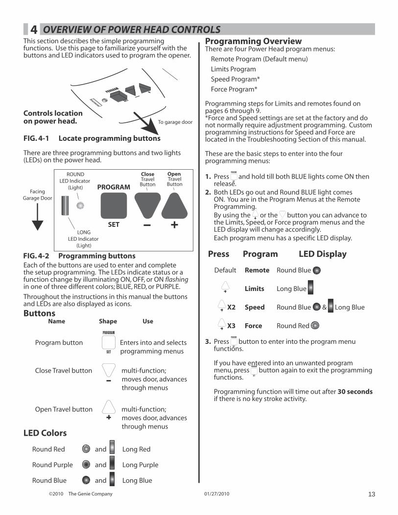
OVERVIEW OF POWER HEAD CONTROLSThis section describes the simple programming functions. Use this page to familiarize yourself with the buttons and LED indicators used to program the opener.
PROGRAM
SET—
+
To garage door
FIG. 4-1 Locate programming buttons
Controls location on power head.
FIG. 4-2 Programming buttons
There are three programming buttons and two lights (LEDs) on the power head.
Each of the buttons are used to enter and complete the setup programming. The LEDs indicate status or a function change by illuminating ON, OFF, or ON flashing in one of three different colors; BLUE, RED, or PURPLE.
Throughout the instructions in this manual the buttons and LEDs are also displayed as icons.
ButtonsName Shape Use
Program button
PROGRAM
SET
Enters into and selects programming menus
Close Travel button multi-function; moves door, advances through menus
Open Travel button multi-function; moves door, advances through menus
LED Colors
Round Red and Long Red
Round Purple and Long Purple
Round Blue and Long Blue
Programming OverviewThere are four Power Head program menus:
Remote Program (Default menu)
Limits Program
Speed Program*
Force Program*
Programming steps for Limits and remotes found on pages 6 through 9.*Force and Speed settings are set at the factory and do not normally require adjustment programming. Custom programming instructions for Speed and Force are located in the Troubleshooting Section of this manual.
These are the basic steps to enter into the four programming menus:
1. Press PROGRAM
SET
and hold till both BLUE lights come ON then release.
2. Both LEDs go out and Round BLUE light comes ON. You are in the Program Menus at the Remote Programming.
By using the or the button you can advance to the Limits, Speed, or Force program menus and the LED display will change accordingly.
Each program menu has a specific LED display.
Press Program LED Display
Default Remote Round Blue
Limits Long Blue
X2 Speed Round Blue & Long Blue
X3 Force Round Red
3. Press PROGRAM
SET
button to enter into the program menu functions.
If you have entered into an unwanted program menu, press
PROGRAM
SET
button again to exit the programming functions.
Programming function will time out after 30 seconds if there is no key stroke activity.
4
©2010 The Genie Company 01/27/201014
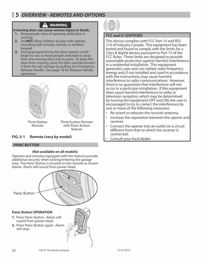
OVERVIEW - REMOTES AND OPTIONS 5
FCC and IC CERTIFIEDThis device complies with FCC Part 15 and RSS 210 of Industry Canada. This equipment has been tested and found to comply with the limits for a Class B digital device, pursuant to Part 15 of the FCC Rules. These limits are designed to provide reasonable protection against harmful interference in a residential installation. This equipment generates, uses and can radiate radio frequency energy and, if not installed and used in accordance with the instructions, may cause harmful interference to radio communications. However, there is no guarantee that interference will not occur in a particular installation. If this equipment does cause harmful interference to radio or television reception, which may be determined by turning the equipment OFF and ON, the user is encouraged to try to correct the interference by one or more of the following measures:• Re-orient or relocate the receiver antenna.• Increase the separation between the opener and
receiver.• Connect the opener into an outlet on a circuit
different from that to which the receiver is connected.
• Consult your local dealer.FIG. 5-1 Remote (vary by model)
WARNING A moving door can cause serious injury or death.
1. Keep people clear of opening while door is moving.
2. Do NOT allow children to play with opener, including wall console, remote, or wireless keypad.
3. During programming, the door opener could begin to run, so keep people and objects away from the moving door and its parts. To keep the door from moving, close the door and disconnect it from the rail carriage by pulling the Emergency Release Handle. See page 18 for Release Handle operation.
Three Button Remote
Three button Remote with Panic Button
feature
Panic Button OPERATION
1. Press Panic Button. Alarm will sound from power head.
2. Press Panic Button again. Alarm will stop.
Panic Button
PANIC BUTTON
(Not available on all models)Openers and remotes equipped with this feature provide additional security when exiting/entering the garage area. The Panic Button is located on the remote as shown below. Alarm will sound from power head.
©2010 The Genie Company 01/27/2010 15
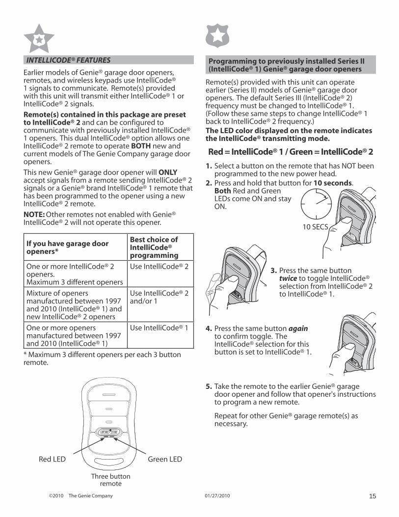
3. Press the same button twice to toggle IntelliCode® selection from IntelliCode® 2 to IntelliCode® 1.
INTELLICODE® FEATURES
Earlier models of Genie® garage door openers, remotes, and wireless keypads use IntelliCode® 1 signals to communicate. Remote(s) provided with this unit will transmit either IntelliCode® 1 or IntelliCode® 2 signals.
Remote(s) contained in this package are preset to IntelliCode® 2 and can be configured to communicate with previously installed IntelliCode® 1 openers. This dual IntelliCode® option allows one IntelliCode® 2 remote to operate BOTH new and current models of The Genie Company garage door openers.
This new Genie® garage door opener will ONLY accept signals from a remote sending IntelliCode® 2 signals or a Genie® brand IntelliCode® 1 remote that has been programmed to the opener using a new IntelliCode® 2 remote.
NOTE: Other remotes not enabled with Genie® IntelliCode® 2 will not operate this opener.
If you have garage door openers*
Best choice of IntelliCode® programming
One or more IntelliCode® 2 openers. Maximum 3 different openers
Use IntelliCode® 2
Mixture of openers manufactured between 1997 and 2010 (IntelliCode® 1) and new IntelliCode® 2 openers
Use IntelliCode® 2 and/or 1
One or more openers manufactured between 1997 and 2010 (IntelliCode® 1)
Use IntelliCode® 1
* Maximum 3 different openers per each 3 button remote.
Programming to previously installed Series II(IntelliCode® 1) Genie® garage door openers
Remote(s) provided with this unit can operate earlier (Series II) models of Genie® garage door openers. The default Series III (IntelliCode® 2) frequency must be changed to IntelliCode® 1. (Follow these same steps to change IntelliCode® 1 back to IntelliCode® 2 frequency.)The LED color displayed on the remote indicates the IntelliCode® transmitting mode.
Red = IntelliCode® 1 / Green = IntelliCode® 2
1. Select a button on the remote that has NOT been programmed to the new power head.
2. Press and hold that button for 10 seconds. Both Red and Green LEDs come ON and stay ON.
10 SECS
4. Press the same button again to confirm toggle. The IntelliCode® selection for this button is set to IntelliCode® 1.
5. Take the remote to the earlier Genie® garage door opener and follow that opener's instructions to program a new remote.
Repeat for other Genie® garage remote(s) as necessary.
Red LED Green LED
Three button remote
©2010 The Genie Company 01/27/201016
TRANSMITTER COMPLIANCE STATEMENTTransmitters comply with all United States and Canadian legal requirements as of the date of manufacture. No warranty is made that they comply with all legal requirements of any other jurisdiction. If transmitters are to be used in another country, the importer must determine compliance with any local laws and regulations which may differ from United States and Canadian requirements prior to use.
Los transmisores cumplen con todas las reglamentaciones legales de los Estados Unidos y del Canadá, en la fecha de fabricación. Ninguna garantía se da que cumplan con todas las reglamentaciones legales de ninguna otra jurisdicción. Si los transmisores se van a utilizar en otro país, el importador debe determinar si cumplen con las reglamentaciones y leyes locales que puedan ser diferentes a las reglamentaciones de los Estados Unidos y del Canadá, antes de usar los mismos.
Les émetteurs sont conformes à la réglementation américaine et canadienne à compter de leur date de fabrication. Aucune garantie n’est stipulée indiquant qu’ils sont conformes à toutes les prescriptions juridiques d’autres autorités. Si les émetteurs sont utilisés dans d’autres pays, il incombe à l’importateur d’en déterminer leur conformité aux lois et règles locales pouvant différer de celles des États-Unis et du Canada avant toute utilisation desdits émetteurs.
Sendegeräte entsprechen allen gesetzlichen Bestimmungen in den USA und Kanada zum Zeitpunkt der Herstellung. Wir übernehmen keine Gewährleistung für die Einhaltung aller gesetzlichen Bestimmungen in anderen Ländern. Sollen Sendegeräte in anderen Ländern eingesetzt werden, so muss der Importeur vor dem Gebrauch sicherstellen, dass die Sendegeräte auch solchen lokalen Bestimmungen entsprechen, welche von den Bestimmungen der USA und Kanadas abweichen.
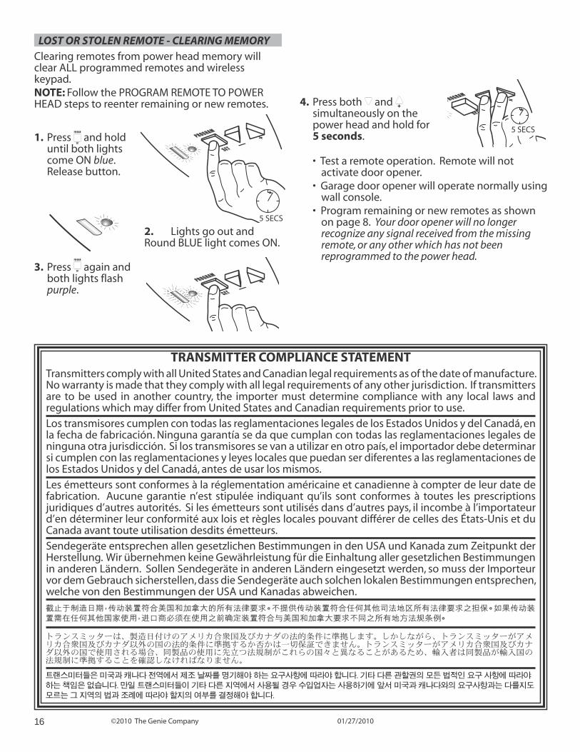
LOST OR STOLEN REMOTE - CLEARING MEMORYClearing remotes from power head memory will clear ALL programmed remotes and wireless keypad.NOTE: Follow the PROGRAM REMOTE TO POWER HEAD steps to reenter remaining or new remotes.
1. Press PROGRAM
SET and hold
until both lights come ON blue. Release button.
2. Lights go out and Round BLUE light comes ON.
3. Press PROGRAM
SET again and both lights flash purple.
PROGRAM
SET—
+
4. Press both and simultaneously on the power head and hold for 5 seconds.
• Test a remote operation. Remote will not activate door opener.
• Garage door opener will operate normally using wall console.
• Program remaining or new remotes as shown on page 8. Your door opener will no longer recognize any signal received from the missing remote, or any other which has not been reprogrammed to the power head.
PROGRAM
SET—
+
5 SECSPROG
RAM
SET—
+
5 SECS
©2010 The Genie Company 01/27/2010 17
MAINTENANCE & TROUBLESHOOTING FOR HELP-1.800.354.3643 OR WWW.GENIECOMPANY.COM6
WARNING • Garage door hardware (springs, cables, brackets,
pulleys, etc.) are under extreme pressure and tension.
• DO NOT attempt to repair or adjust door springs or any hardware, and DO NOT OPERATE garage door automatically or manually if door is improperly balanced or springs are broken.– CONTACT A TRAINED DOOR SYSTEM
TECHNICIAN.
ROUTINE MONTHLY MAINTENANCEBasic monthly maintenance tasks.
• Door balance• Safe-T-Beam® System Check• Contact reverse
Instructions for these tasks and others are found on the following pages.
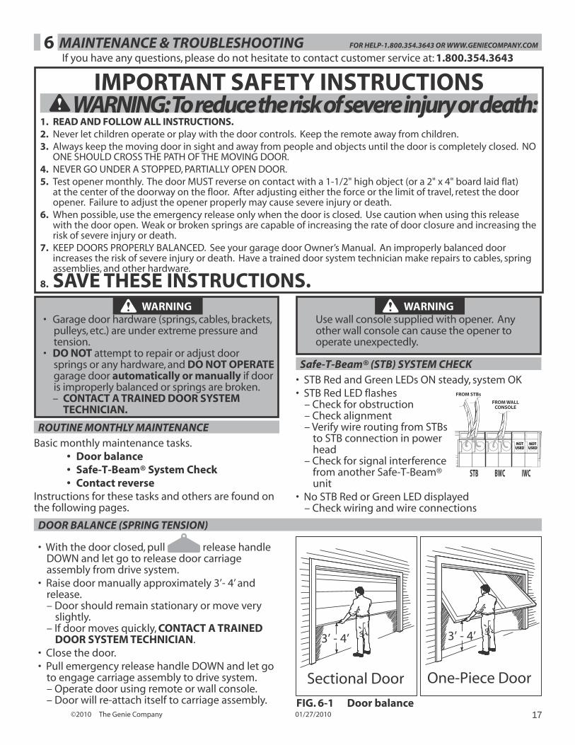
DOOR BALANCE (SPRING TENSION)
• With the door closed, pull release handle DOWN and let go to release door carriage assembly from drive system.
• Raise door manually approximately 3’- 4’ and release.– Door should remain stationary or move very
slightly.– If door moves quickly, CONTACT A TRAINED
DOOR SYSTEM TECHNICIAN.• Close the door.• Pull emergency release handle DOWN and let go
to engage carriage assembly to drive system.– Operate door using remote or wall console.– Door will re-attach itself to carriage assembly.
If you have any questions, please do not hesitate to contact customer service at: 1.800.354.3643
3’ - 4’
Sectional Door
3’ - 4’
One-Piece Door
FIG. 6-1 Door balance
WARNING Use wall console supplied with opener. Any other wall console can cause the opener to operate unexpectedly.
Safe-T-Beam® (STB) SYSTEM CHECK• STB Red and Green LEDs ON steady, system OK• STB Red LED flashes
– Check for obstruction– Check alignment– Verify wire routing from STBs
to STB connection in power head
– Check for signal interference from another Safe-T-Beam® unit
• No STB Red or Green LED displayed– Check wiring and wire connections
STB BWC IWC
NOTUSED
NOTUSED
NOTUSED
NOTUSED
FROM STBs
FROM WALLCONSOLE
IMPORTANT SAFETY INSTRUCTIONS WARNING: To reduce the risk of severe injury or death:
1. READ AND FOLLOW ALL INSTRUCTIONS.2. Never let children operate or play with the door controls. Keep the remote away from children.3. Always keep the moving door in sight and away from people and objects until the door is completely closed. NO
ONE SHOULD CROSS THE PATH OF THE MOVING DOOR.4. NEVER GO UNDER A STOPPED, PARTIALLY OPEN DOOR.5. Test opener monthly. The door MUST reverse on contact with a 1-1/2" high object (or a 2" x 4" board laid flat)
at the center of the doorway on the floor. After adjusting either the force or the limit of travel, retest the door opener. Failure to adjust the opener properly may cause severe injury or death.
6. When possible, use the emergency release only when the door is closed. Use caution when using this release with the door open. Weak or broken springs are capable of increasing the rate of door closure and increasing the risk of severe injury or death.
7. KEEP DOORS PROPERLY BALANCED. See your garage door Owner’s Manual. An improperly balanced door increases the risk of severe injury or death. Have a trained door system technician make repairs to cables, spring assemblies, and other hardware.
8. SAVE THESE INSTRUCTIONS.
©2010 The Genie Company 01/27/201018
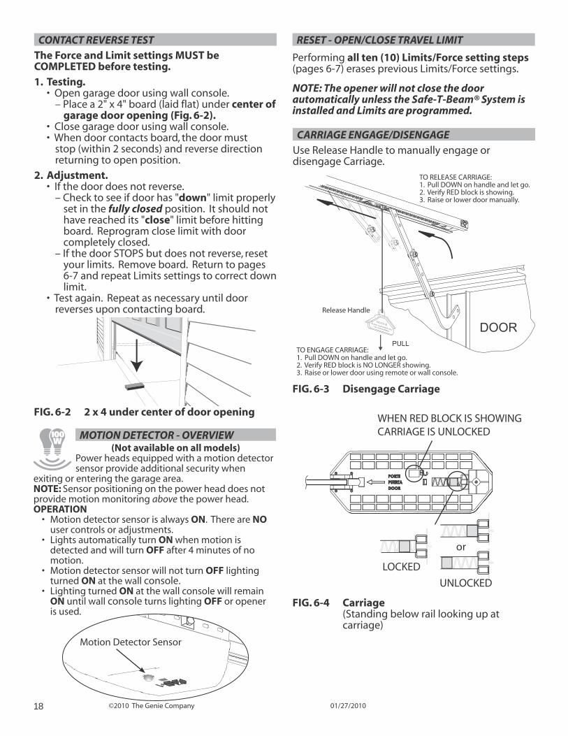
CARRIAGE ENGAGE/DISENGAGEUse Release Handle to manually engage or disengage Carriage.
RESET - OPEN/CLOSE TRAVEL LIMIT
Performing all ten (10) Limits/Force setting steps (pages 6-7) erases previous Limits/Force settings.
NOTE: The opener will not close the door automatically unless the Safe-T-Beam® System is installed and Limits are programmed.
MOTION DETECTOR - OVERVIEW(Not available on all models)
Power heads equipped with a motion detector sensor provide additional security when
exiting or entering the garage area.NOTE: Sensor positioning on the power head does not provide motion monitoring above the power head. OPERATION
• Motion detector sensor is always ON. There are NO user controls or adjustments.
• Lights automatically turn ON when motion is detected and will turn OFF after 4 minutes of no motion.
• Motion detector sensor will not turn OFF lighting turned ON at the wall console.
• Lighting turned ON at the wall console will remain ON until wall console turns lighting OFF or opener is used.
PROGRAMT — +
Motion Detector Sensor
CONTACT REVERSE TESTThe Force and Limit settings MUST be COMPLETED before testing.1. Testing.
• Open garage door using wall console.– Place a 2" x 4" board (laid flat) under center of
garage door opening (Fig. 6-2).• Close garage door using wall console.• When door contacts board, the door must
stop (within 2 seconds) and reverse direction returning to open position.
2. Adjustment.• If the door does not reverse.
– Check to see if door has "down" limit properly set in the fully closed position. It should not have reached its "close" limit before hitting board. Reprogram close limit with door completely closed.
– If the door STOPS but does not reverse, reset your limits. Remove board. Return to pages 6-7 and repeat Limits settings to correct down limit.
• Test again. Repeat as necessary until door reverses upon contacting board.
FIG. 6-2 2 x 4 under center of door opening
NOTICEF DOOR B COMES OBSTRUCTED
PULL DOWN ON HANDLE
TO RELEASE CARRIAGE:1. Pull DOWN on handle and let go.2. Verify RED block is showing.3. Raise or lower door manually.
DOORPULL
TO ENGAGE CARRIAGE:1. Pull DOWN on handle and let go.2. Verify RED block is NO LONGER showing.3. Raise or lower door using remote or wall console.
Release Handle
FIG. 6-3 Disengage Carriage
LOCKED
UNLOCKED
WHEN RED BLOCK IS SHOWINGCARRIAGE IS UNLOCKED
or
FIG. 6-4 Carriage (Standing below rail looking up at carriage)
©2010 The Genie Company 01/27/2010 19
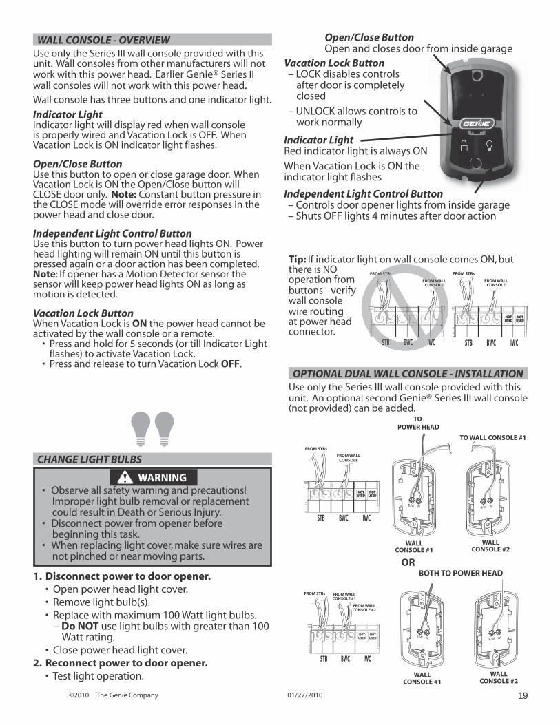
Independent Light Control Button– Controls door opener lights from inside garage– Shuts OFF lights 4 minutes after door action
Vacation Lock Button– LOCK disables controls after door is completely closed
– UNLOCK allows controls to work normally
Indicator LightRed indicator light is always ON
When Vacation Lock is ON the indicator light flashes
Open/Close ButtonOpen and closes door from inside garage
WALL CONSOLE - OVERVIEWUse only the Series III wall console provided with this unit. Wall consoles from other manufacturers will not work with this power head. Earlier Genie® Series II wall consoles will not work with this power head.Wall console has three buttons and one indicator light.
Indicator LightIndicator light will display red when wall console is properly wired and Vacation Lock is OFF. When Vacation Lock is ON indicator light flashes.
Open/Close ButtonUse this button to open or close garage door. When Vacation Lock is ON the Open/Close button will CLOSE door only. Note: Constant button pressure in the CLOSE mode will override error responses in the power head and close door.
Independent Light Control ButtonUse this button to turn power head lights ON. Power head lighting will remain ON until this button is pressed again or a door action has been completed. Note: If opener has a Motion Detector sensor the sensor will keep power head lights ON as long as motion is detected.
Vacation Lock ButtonWhen Vacation Lock is ON the power head cannot be activated by the wall console or a remote.
• Press and hold for 5 seconds (or till Indicator Light flashes) to activate Vacation Lock.
• Press and release to turn Vacation Lock OFF. OPTIONAL DUAL WALL CONSOLE - INSTALLATION
Use only the Series III wall console provided with this unit. An optional second Genie® Series III wall console (not provided) can be added.
OR
STB BWC IWC
NOTUSED
NOTUSED
FROM STBs FROM WALLCONSOLE #1
FROM WALLCONSOLE #2
TO POWER HEAD
WALLCONSOLE #1
WALLCONSOLE #2
TO WALL CONSOLE #1
WB/W WB/W
WB/W WB/W
BOTH TO POWER HEAD
WALLCONSOLE #1
WALLCONSOLE #2
STB BWC IWC
NOTUSED
NOTUSED
NOTUSED
NOTUSED
FROM STBs
FROM WALLCONSOLE
Tip: If indicator light on wall console comes ON, but there is NO operation from buttons - verify wall console wire routing at power head connector.
STB BWC IWC
NOTUSED
NOTUSED
NOTUSED
NOTUSED
FROM STBs
FROM WALLCONSOLE
STB BWC IWC
FRO STBs
FROM WALLCONSOLE
STB BWC IWC
OM STBs
ROM WAOM WOLEONSO
CHANGE LIGHT BULBS
WARNING • Observe all safety warning and precautions!
Improper light bulb removal or replacement could result in Death or Serious Injury.
• Disconnect power from opener before beginning this task.
• When replacing light cover, make sure wires are not pinched or near moving parts.
1. Disconnect power to door opener.• Open power head light cover.• Remove light bulb(s).• Replace with maximum 100 Watt light bulbs.
– Do NOT use light bulbs with greater than 100 Watt rating.
• Close power head light cover.2. Reconnect power to door opener.
• Test light operation.
©2010 The Genie Company 01/27/201020
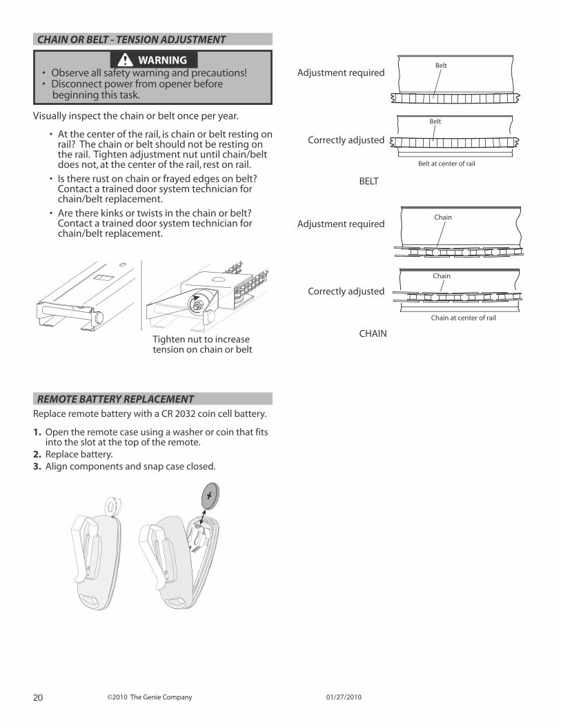
CHAIN OR BELT - TENSION ADJUSTMENT
WARNING • Observe all safety warning and precautions!• Disconnect power from opener before
beginning this task.
Visually inspect the chain or belt once per year.
• At the center of the rail, is chain or belt resting on rail? The chain or belt should not be resting on the rail. Tighten adjustment nut until chain/belt does not, at the center of the rail, rest on rail.
• Is there rust on chain or frayed edges on belt? Contact a trained door system technician for chain/belt replacement.
• Are there kinks or twists in the chain or belt? Contact a trained door system technician for chain/belt replacement.
Tighten nut to increase tension on chain or belt
Chain
Chain
Chain at center of rail
Adjustment required
Correctly adjusted
Belt
Belt
Belt at center of rail
Adjustment required
Correctly adjusted
BELT
CHAIN
REMOTE BATTERY REPLACEMENTReplace remote battery with a CR 2032 coin cell battery.
1. Open the remote case using a washer or coin that fits into the slot at the top of the remote.
2. Replace battery.3. Align components and snap case closed.
©2010 The Genie Company 01/27/2010 21
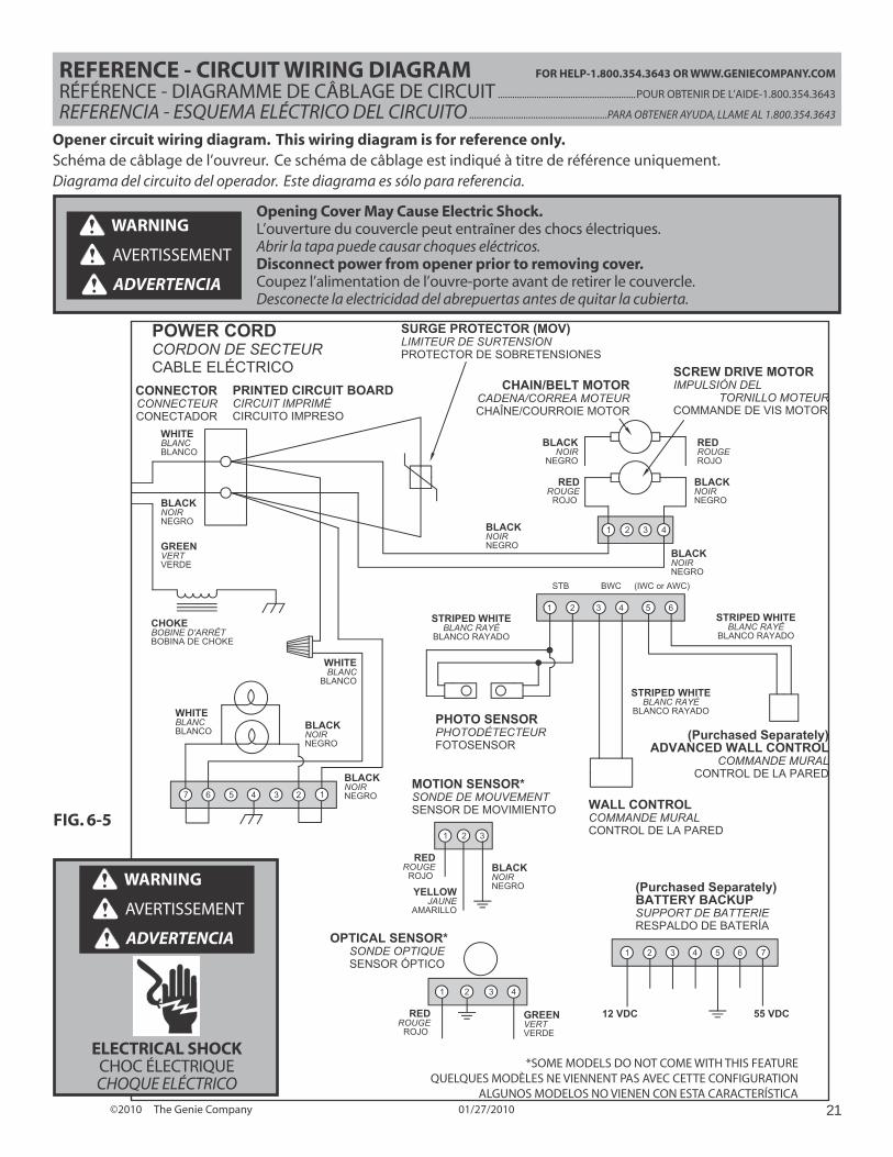
REFERENCE - CIRCUIT WIRING DIAGRAM FOR HELP-1.800.354.3643 OR WWW.GENIECOMPANY.COM
RÉFÉRENCE - DIAGRAMME DE CÂBLAGE DE CIRCUIT .........................................................POUR OBTENIR DE L’AIDE-1.800.354.3643
REFERENCIA - ESQUEMA ELÉCTRICO DEL CIRCUITO ........................................................PARA OBTENER AYUDA, LLAME AL 1.800.354.3643
Opener circuit wiring diagram. This wiring diagram is for reference only.Schéma de câblage de l’ouvreur. Ce schéma de câblage est indiqué à titre de référence uniquement.Diagrama del circuito del operador. Este diagrama es sólo para referencia.
Opening Cover May Cause Electric Shock.L’ouverture du couvercle peut entraîner des chocs électriques.Abrir la tapa puede causar choques eléctricos.Disconnect power from opener prior to removing cover.Coupez l’alimentation de l’ouvre-porte avant de retirer le couvercle.Desconecte la electricidad del abrepuertas antes de quitar la cubierta.
WARNING
AVERTISSEMENT
ADVERTENCIA
654321
1 2 3
7 6
POWER CORDCORDON DE SECTEURCABLE ELÉCTRICO
CONNECTORCONNECTEURCONECTADOR
WHITEBLANCBLANCO
BLACKNOIRNEGRO
GREENVERTVERDE
SURGE PROTECTOR (MOV)LIMITEUR DE SURTENSIONPROTECTOR DE SOBRETENSIONES
BLACKNOIRNEGRO
BLACKNOIRNEGRO
WHITEBLANCBLANCO
WHITEBLANC
BLANCO
BLACKNOIRNEGRO
REDROUGE
ROJO
BLACKNOIRNEGRO
STRIPED WHITEBLANC RAYÉ
BLANCO RAYADO
WALL CONTROLCOMMANDE MURALCONTROL DE LA PARED
SCREW DRIVE MOTORIMPULSIÓN DEL TORNILLO MOTEURCOMMANDE DE VIS MOTOR
STRIPED WHITEBLANC RAYÉ
BLANCO RAYADO
PHOTO SENSORPHOTODÉTECTEURFOTOSENSOR
5 4 3 2 1
(Purchased Separately)ADVANCED WALL CONTROL
COMMANDE MURALCONTROL DE LA PARED
STRIPED WHITEBLANC RAYÉ
BLANCO RAYADO
4
BLACKNOIRNEGRO
REDROUGEROJO
BLACKNOIR
NEGRO
CHAIN/BELT MOTORCADENA/CORREA MOTEURCHAÎNE/COURROIE MOTOR
1 2 3
1 2 3 4 5 6 7
(Purchased Separately)BATTERY BACKUPSUPPORT DE BATTERIERESPALDO DE BATERÍA
MOTION SENSOR*SONDE DE MOUVEMENTSENSOR DE MOVIMIENTO
REDROUGE
ROJO BLACKNOIRNEGROYELLOW
JAUNEAMARILLO
1 2 3 4
OPTICAL SENSOR*SONDE OPTIQUE SENSOR ÓPTICO
GREENVERTVERDE
REDROUGE
ROJO
12 VDC 55 VDC
PRINTED CIRCUIT BOARDCIRCUIT IMPRIMÉ CIRCUITO IMPRESO
CHOKEBOBINE D'ARRÊT BOBINA DE CHOKE
*SOME MODELS DO NOT COME WITH THIS FEATUREQUELQUES MODÈLES NE VIENNENT PAS AVEC CETTE CONFIGURATION
ALGUNOS MODELOS NO VIENEN CON ESTA CARACTERÍSTICA
(IWC or AWC)BWCSTB
WARNING
AVERTISSEMENT
ADVERTENCIA
ELECTRICAL SHOCKCHOC ÉLECTRIQUECHOQUE ELÉCTRICO
FIG. 6-5
©2010 The Genie Company 01/27/201022
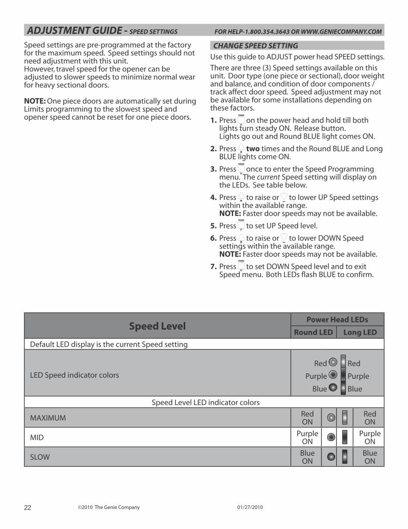
ADJUSTMENT GUIDE - SPEED SETTINGS FOR HELP-1.800.354.3643 OR WWW.GENIECOMPANY.COM
Speed settings are pre-programmed at the factory for the maximum speed. Speed settings should not need adjustment with this unit.However, travel speed for the opener can be adjusted to slower speeds to minimize normal wear for heavy sectional doors.
NOTE: One piece doors are automatically set during Limits programming to the slowest speed and opener speed cannot be reset for one piece doors.
CHANGE SPEED SETTINGUse this guide to ADJUST power head SPEED settings.
There are three (3) Speed settings available on this unit. Door type (one piece or sectional), door weight and balance, and condition of door components / track affect door speed. Speed adjustment may not be available for some installations depending on these factors.
1. Press PROGRAM
SET on the power head and hold till both
lights turn steady ON. Release button. Lights go out and Round BLUE light comes ON.
2. Press two times and the Round BLUE and Long BLUE lights come ON.
3. Press PROGRAM
SET once to enter the Speed Programming
menu. The current Speed setting will display on the LEDs. See table below.
4. Press to raise or to lower UP Speed settings within the available range. NOTE: Faster door speeds may not be available.
5. Press PROGRAM
SET to set UP Speed level.
6. Press to raise or to lower DOWN Speed settings within the available range. NOTE: Faster door speeds may not be available.
7. Press PROGRAM
SET to set DOWN Speed level and to exit
Speed menu. Both LEDs flash BLUE to confirm.
Speed LevelPower Head LEDs
Round LED Long LED
Default LED display is the current Speed setting
LED Speed indicator colors
Red Red
Purple Purple
Blue Blue
Speed Level LED indicator colors
MAXIMUM RedON
RedON
MID PurpleON
PurpleON
SLOW BlueON
BlueON
©2010 The Genie Company 01/27/2010 23
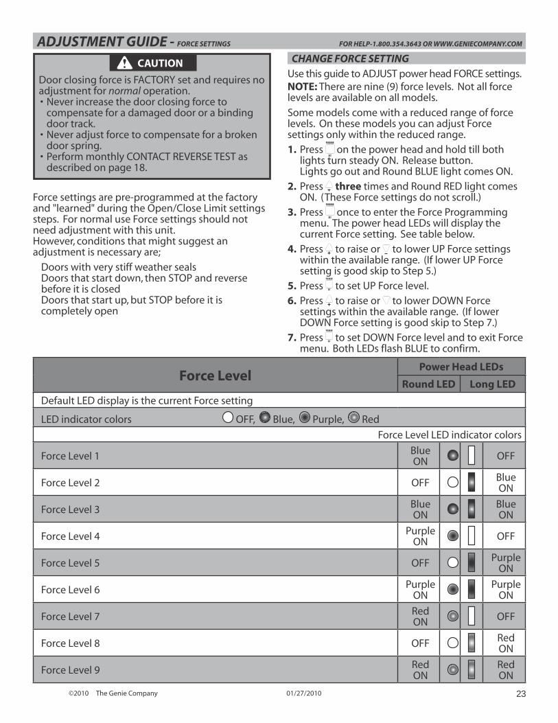
ADJUSTMENT GUIDE - FORCE SETTINGS FOR HELP-1.800.354.3643 OR WWW.GENIECOMPANY.COM
Force settings are pre-programmed at the factory and "learned" during the Open/Close Limit settings steps. For normal use Force settings should not need adjustment with this unit.However, conditions that might suggest an adjustment is necessary are;
Doors with very stiff weather sealsDoors that start down, then STOP and reverse before it is closedDoors that start up, but STOP before it is completely open
Force LevelPower Head LEDs
Round LED Long LED
Default LED display is the current Force setting
LED indicator colors OFF, Blue, Purple, Red
Force Level LED indicator colors
Force Level 1 BlueON OFF
Force Level 2 OFF BlueON
Force Level 3 BlueON
BlueON
Force Level 4 PurpleON OFF
Force Level 5 OFF Purple
ON
Force Level 6 PurpleON
PurpleON
Force Level 7 RedON OFF
Force Level 8 OFF RedON
Force Level 9 RedON
RedON
CAUTION
Door closing force is FACTORY set and requires no adjustment for normal operation.• Never increase the door closing force to
compensate for a damaged door or a binding door track.
• Never adjust force to compensate for a broken door spring.
• Perform monthly CONTACT REVERSE TEST as described on page 1 .
CHANGE FORCE SETTINGUse this guide to ADJUST power head FORCE settings.NOTE: There are nine (9) force levels. Not all force levels are available on all models.
Some models come with a reduced range of force levels. On these models you can adjust Force settings only within the reduced range.
1. Press PROGRAM
SET on the power head and hold till both
lights turn steady ON. Release button. Lights go out and Round BLUE light comes ON.
2. Press three times and Round RED light comes ON. (These Force settings do not scroll.)
3. Press PROGRAM
SET once to enter the Force Programming
menu. The power head LEDs will display the current Force setting. See table below.
4. Press to raise or to lower UP Force settings within the available range. (If lower UP Force setting is good skip to Step 5.)
5. Press PROGRAM
SET to set UP Force level.
6. Press to raise or to lower DOWN Force settings within the available range. (If lower DOWN Force setting is good skip to Step 7.)
7. Press PROGRAM
SET to set DOWN Force level and to exit Force menu. Both LEDs flash BLUE to confirm.
©2010 The Genie Company 01/27/201024
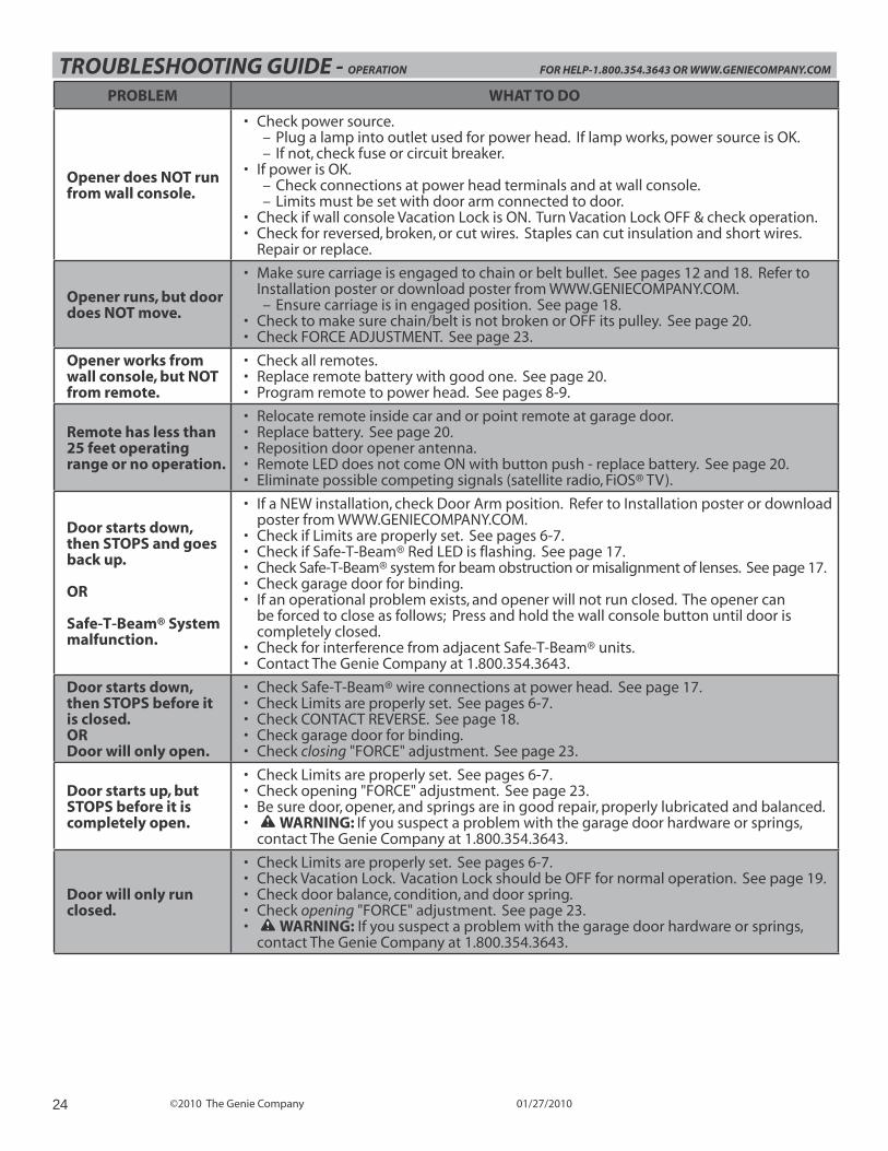
TROUBLESHOOTING GUIDE - OPERATION FOR HELP-1.800.354.3643 OR WWW.GENIECOMPANY.COM
PROBLEM WHAT TO DO
Opener does NOT run from wall console.
• Check power source.– Plug a lamp into outlet used for power head. If lamp works, power source is OK.– If not, check fuse or circuit breaker.
• If power is OK.– Check connections at power head terminals and at wall console.– Limits must be set with door arm connected to door.
• Check if wall console Vacation Lock is ON. Turn Vacation Lock OFF & check operation.• Check for reversed, broken, or cut wires. Staples can cut insulation and short wires.
Repair or replace.
Opener runs, but door does NOT move.
• Make sure carriage is engaged to chain or belt bullet. See pages 12 and 18. Refer to Installation poster or download poster from WWW.GENIECOMPANY.COM.– Ensure carriage is in engaged position. See page 18.
• Check to make sure chain/belt is not broken or OFF its pulley. See page 20.• Check FORCE ADJUSTMENT. See page 23.
Opener works from wall console, but NOT from remote.
• Check all remotes.• Replace remote battery with good one. See page 20.• Program remote to power head. See pages 8-9.
Remote has less than 25 feet operating range or no operation.
• Relocate remote inside car and or point remote at garage door.• Replace battery. See page 20.• Reposition door opener antenna.• Remote LED does not come ON with button push - replace battery. See page 20.• Eliminate possible competing signals (satellite radio, FiOS® TV).
Door starts down, then STOPS and goes back up.
OR
Safe-T-Beam® System malfunction.
• If a NEW installation, check Door Arm position. Refer to Installation poster or download poster from WWW.GENIECOMPANY.COM.
• Check if Limits are properly set. See pages 6-7.• Check if Safe-T-Beam® Red LED is flashing. See page 17.• Check Safe-T-Beam® system for beam obstruction or misalignment of lenses. See page 17.• Check garage door for binding.• If an operational problem exists, and opener will not run closed. The opener can
be forced to close as follows; Press and hold the wall console button until door is completely closed.
• Check for interference from adjacent Safe-T-Beam® units.• Contact The Genie Company at 1.800.354.3643.
Door starts down, then STOPS before it is closed.ORDoor will only open.
• Check Safe-T-Beam® wire connections at power head. See page 17.• Check Limits are properly set. See pages 6-7.• Check CONTACT REVERSE. See page 18.• Check garage door for binding.• Check closing "FORCE" adjustment. See page 23.
Door starts up, but STOPS before it is completely open.
• Check Limits are properly set. See pages 6-7.• Check opening "FORCE" adjustment. See page 23.• Be sure door, opener, and springs are in good repair, properly lubricated and balanced.• WARNING: If you suspect a problem with the garage door hardware or springs,
contact The Genie Company at 1.800.354.3643.
Door will only run closed.
• Check Limits are properly set. See pages 6-7.• Check Vacation Lock. Vacation Lock should be OFF for normal operation. See page 19.• Check door balance, condition, and door spring.• Check opening "FORCE" adjustment. See page 23.• WARNING: If you suspect a problem with the garage door hardware or springs,
contact The Genie Company at 1.800.354.3643.
©2010 The Genie Company 01/27/2010 25
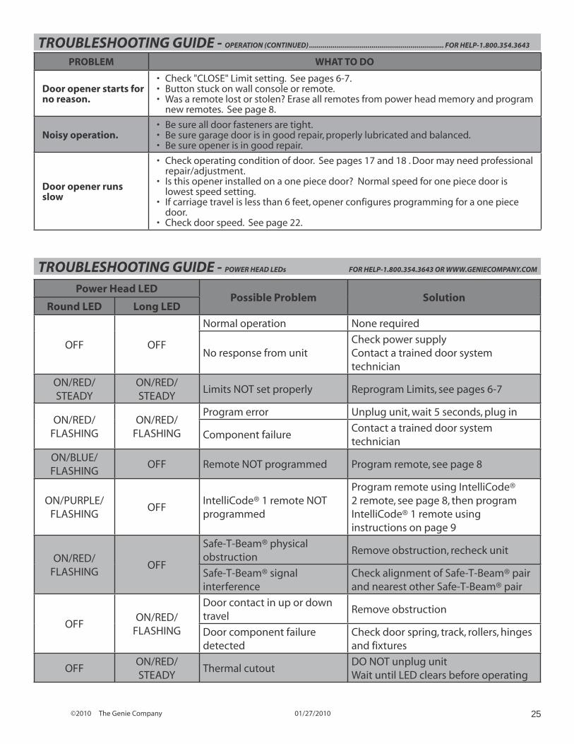
TROUBLESHOOTING GUIDE - POWER HEAD LEDs FOR HELP-1.800.354.3643 OR WWW.GENIECOMPANY.COM
Power Head LEDPossible Problem Solution
Round LED Long LED
OFF OFF
Normal operation None required
No response from unitCheck power supplyContact a trained door system technician
ON/RED/STEADY
ON/RED/STEADY
Limits NOT set properly Reprogram Limits, see pages 6-7
ON/RED/FLASHING
ON/RED/FLASHING
Program error Unplug unit, wait 5 seconds, plug in
Component failureContact a trained door system technician
ON/BLUE/FLASHING
OFF Remote NOT programmed Program remote, see page 8
ON/PURPLE/FLASHING
OFFIntelliCode® 1 remote NOT programmed
Program remote using IntelliCode® 2 remote, see page 8, then program IntelliCode® 1 remote using instructions on page 9
ON/RED/FLASHING
OFF
Safe-T-Beam® physical obstruction
Remove obstruction, recheck unit
Safe-T-Beam® signal interference
Check alignment of Safe-T-Beam® pair and nearest other Safe-T-Beam® pair
OFFON/RED/
FLASHING
Door contact in up or down travel
Remove obstruction
Door component failure detected
Check door spring, track, rollers, hinges and fixtures
OFFON/RED/STEADY
Thermal cutoutDO NOT unplug unit Wait until LED clears before operating
TROUBLESHOOTING GUIDE - OPERATION (CONTINUED) ..................................................................... FOR HELP-1.800.354.3643
PROBLEM WHAT TO DO
Door opener starts for no reason.
• Check "CLOSE" Limit setting. See pages 6-7.• Button stuck on wall console or remote.• Was a remote lost or stolen? Erase all remotes from power head memory and program
new remotes. See page 8.
Noisy operation.• Be sure all door fasteners are tight.• Be sure garage door is in good repair, properly lubricated and balanced.• Be sure opener is in good repair.
Door opener runs slow
• Check operating condition of door. See pages 17 and 18 . Door may need professional repair/adjustment.
• Is this opener installed on a one piece door? Normal speed for one piece door is lowest speed setting.
• If carriage travel is less than 6 feet, opener configures programming for a one piece door.
• Check door speed. See page 22.

P900-787
Limited Warranty