Embed Size (px)
Citation preview
1 | P a g e
ASSEMBLY INSTRUCTIONS
T-1000
&
T-2000
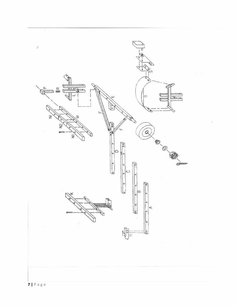
All instructions reference the exploded diagram of the T-2000 trailer shown
on page 7 and the rear bunk assembly diagram on page 8.
Before beginning the assembly, review all the instructions and identify all
the parts. A list of fasteners is provided on page 10. Washers have been
provided for your convenience and can be used at all locations where bolt
heads and nuts touch painted surfaces.
Recommended tools for assembly include 1/2 inch and 9/16 inch open end
wrenches (or adjustable wrench), a set of American standard sockets, a
pliers and a hammer.
During initial assembly, tighten all fasteners finger tight only. Fully tighten
only after all the components have been assembled. References to right
hand and left hand sides are as you stand behind the trailer facing forward.
2 | P a g e
TONGUE SECTIONS
Identify tongue sections A, B, C and D by referencing the diagram on page
10. Sections A & C are 2” x 2” galvanized square tube and sections B & D
are 1 ¾” x 1 ¾” galvanized square tube.
Standard Trailer
If you have ordered a standard trailer you will have tongue sections A and
D.
Trailer with Tongue Extension
If you have ordered a trailer with tongue extensions you will have tongue
sections A, B, C, and D.
Accessories
Instructions for any accessories that you may have ordered can be found
on page 12.
ASSEMBLY
1) The wiring harness can either be attached externally to the tongue or
can be run inside the tongue. If you choose to run the wiring inside
the tongue, lay the sections out as they will be when completely
assembled. REMEMBER: THE HOLES IN THE TONGUE
SECTIONS ARE DRILLED OFF-CENTER. THE HOLES
NEED TO BE ON THE SIDES BUT CLOSEST TO THE
BOTTOM.
Feed the wiring harness through the tongue leaving the “Plug End”
of the harness extending one (1) foot past the coupler end of tongue
section “A”. You will want to leave NO MORE THAN three (3) feet of
wiring out of the axle end of tongue section “D”. If more wiring is
needed you will be able to pull more out of the tongue which is easier
3 | P a g e
than pushing it back in. The white wire is attached by the ring terminal
to the bolts that attach the coupler to the tongue section.
If you place the wiring “OVER” the bolts that attach the coupler it will
protect the wiring from the edges of the tongue section.
The axle is pre-drilled to allow the wiring harness to exit the tongue.
A rubber grommet is provided to protect the wire as it passes through
the axle. The yellow/brown wires will extend to the left rear light and
the green/brown wires will extend to the right rear light. The wiring
should go under or inside the axle and out on each side through the
rubber grommets provided on each side. It should then be routed
through the fender brackets and snugly attached with the 8” cable ties
provided. Wiring instructions and helpful hints can be found on pages
13 & 14.
2) Attach tongue section (D) to the axle (E) using two (2) 3/8 inch X 3
inch cap screws with nylon insert nuts (washers optional). Attach
coupler to section (A) using two (2) 3/8 inch X 3 inch cap screws with
nylon insert nuts. The two (2) safety chains and the white ground wire
are also attached during this step. Attach the non-hook end of each
safety chain to a separate bolt. A safety chain should be attached to
each side of the coupler. Section (A) will now slip over section (D).
Adjust the tongue to your desired length. Securely connect each
tongue section to its adjoining section using two (2) each 3/8” x 3 inch
cap screw with nylon insert nuts.
A ONE (1) FOOT OVERLAP IS REQUIRED AT EACH
SECTION.
If you have ordered a trailer with tongue extensions you will have
sections (A), (B), (C) and (D) to connect together and secure with
bolts.
3) The stiffener bars (F) are installed at this point. Refer to the diagram
on page 7. The longer of the two is used to diagonally attach the
tongue to the axle on the right side and remaining (shorter) one
4 | P a g e
attaches on the left side. Place each on top of the axle and the
tongue and align the holes. Insert a 3/8” X 3 ½” cap screw in each
where they attach to the tongue and secure with nylon insert nuts.
The axle end will be attached in step 4 below.
4) Slide fender brackets (L) over the axle at each end. Line up the hole
in the top of the axle with the diagonal stiffener and with the hole in
the fender bracket. Attach with the 3/8” X 2” cap screws with the
nylon insert nuts. Insert the 3/8” X 5” cap screw (washer optional)
through the holes in the bottom-most part of the fender bracket (it will
pass through both pieces of the fender bracket under the axle.
Secure with a nylon insert nut (washer optional).
5) Mount the forward bunk (J) to a (A) or (C) section of the tongue with
one (1) 3/8” X 3” cap screw and nylon insert nut previously installed in
step two (2)(washers optional). This forward bunk can be moved
forward or backward to a point that best satisfies your requirements.
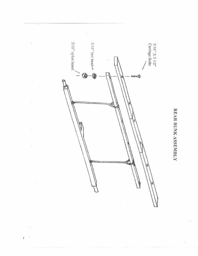
6) Attach rear bunk (M) as shown on pages 7 & 8. You will be using the
front (of forward) of the two (2) square tubes on the fender bracket
(L). First insert the coil springs (R) with the ground (or flattened) end
up. Now is the best time to apply a small amount of grease
(included). Apply some to the inside walls of the square tube you just
installed the spring and a little to the bottom half (1/2) of the bunk
support T-posts (P). Insert T-posts (P). Bar (M) is now installed
laterally through these T-posts (P) and through the 1” black nylon
webbing loops that are attached to the axle as shown on pages 8.
Carpet covered wooden bunks are now installed using 5/16” X 3 ½”
carriage bolts. The holes are pre-drilled but may be hard to see
through the carpet.
T-2000 has two (2) “N1” pieces and one (1) “N2” piece.
T-1000 has only two (2) “N1” pieces.
5 | P a g e
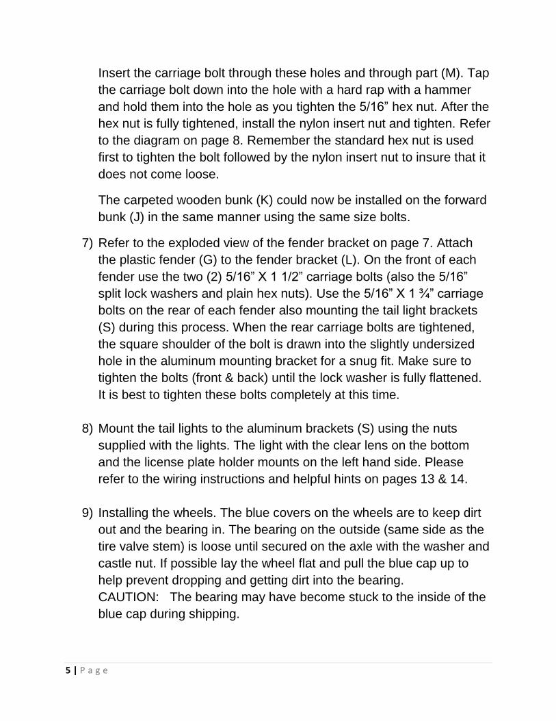
Insert the carriage bolt through these holes and through part (M). Tap
the carriage bolt down into the hole with a hard rap with a hammer
and hold them into the hole as you tighten the 5/16” hex nut. After the
hex nut is fully tightened, install the nylon insert nut and tighten. Refer
to the diagram on page 8. Remember the standard hex nut is used
first to tighten the bolt followed by the nylon insert nut to insure that it
does not come loose.
The carpeted wooden bunk (K) could now be installed on the forward
bunk (J) in the same manner using the same size bolts.
7) Refer to the exploded view of the fender bracket on page 7. Attach
the plastic fender (G) to the fender bracket (L). On the front of each
fender use the two (2) 5/16” X 1 1/2” carriage bolts (also the 5/16”
split lock washers and plain hex nuts). Use the 5/16” X 1 ¾” carriage
bolts on the rear of each fender also mounting the tail light brackets
(S) during this process. When the rear carriage bolts are tightened,
the square shoulder of the bolt is drawn into the slightly undersized
hole in the aluminum mounting bracket for a snug fit. Make sure to
tighten the bolts (front & back) until the lock washer is fully flattened.
It is best to tighten these bolts completely at this time.
8) Mount the tail lights to the aluminum brackets (S) using the nuts
supplied with the lights. The light with the clear lens on the bottom
and the license plate holder mounts on the left hand side. Please
refer to the wiring instructions and helpful hints on pages 13 & 14.
9) Installing the wheels. The blue covers on the wheels are to keep dirt
out and the bearing in. The bearing on the outside (same side as the
tire valve stem) is loose until secured on the axle with the washer and
castle nut. If possible lay the wheel flat and pull the blue cap up to
help prevent dropping and getting dirt into the bearing.
CAUTION: The bearing may have become stuck to the inside of the
blue cap during shipping.
6 | P a g e
The wheel is placed on the axle with the installed bearing and
bearing seal facing inward (tire valve stem out), gently slide it onto
the axle. Install the washer and castle nut. The castle nut is installed
with the slotted end facing outward and is installed finger tight. The
nut should be tightened enough to restrict side play when the wheel
is spun but not produce noticeable drag.
10) Install the cotter pin between the castle nut slots and through
the hole at the end of the axle. Bend the extending halves of the
cotter pin to provide permanent attachment. Install the bearing wheel
dust cap. The cap has a very tight fit to the wheel. It is suggested to
be sure that there are no burs on the lip of the dust cap. The cap
installation is most easily accomplished by carefully aligning the cap
with the wheel assembly and then either tapping it in place with a
rubber mallet or by placing a piece of lumber against the cap face
and very solidly tapping it with a hammer. Repeat the procedure for
the other wheel.
If the trailer is to be repeatedly immersed in the water it is advisable
to purchase and install inexpensive “bearing protectors”.
BE SURE TO TIGHTEN ALL NUTS AND BOLTS
ON THE TRAILER PRIOR TO USE
Thank you for purchasing a Portage Pal trailer. If at anytime during the
assembly process you have any questions, please call us for assistance.
All of us here at Portage Pal hope you enjoy your trailer. If you have any
questions, concerns, problems or comments (good or bad) with your
Portage Pal , please feel free to contact us.
1-800-577-5080 [email protected]
7 | P a g e
8 | P a g e
9 | P a g e
Vehicle Identification Number Decal
&
Tire Information Decal
The “Vehicle Identification Number” “VIN” decal and the “Tire Information
Decal” should be attached after the trailer is completely assembled and the
front bunk bracket at the location on the tongue you have chosen. The
“VIN” and “Tire” decal should be affixed to the tongue towards the front on
the driver side. The intent is for them to be visible from the driver side
without removing any parts.
REGISTRATION
Your trailer can be registered and licensed. We provide a “Certificate of
Origin for a Vehicle” to your dealer for this purpose that will complete it with
their information and forward it on to you. Every state is different but this
should meet any requirements and allow you to license your trailer in your
state.
If you do not receive this “Certificate” contact your dealer first. If they are
unable to assist you please contact Portage Pal.
10 | P a g e
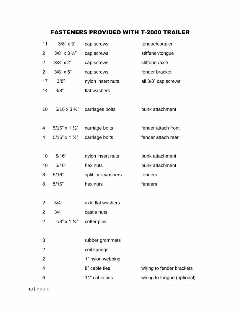
FASTENERS PROVIDED WITH T-2000 TRAILER
11 3/8” x 3” cap screws tongue/coupler
2 3/8” x 3 ½” cap screws stiffener/tongue
2 3/8” x 2” cap screws stiffener/axle
2 3/8” x 5” cap screws fender bracket
17 3/8” nylon insert nuts all 3/8” cap screws
14 3/8” flat washers
10 5/16 x 3 ½” carriages bolts bunk attachment
4 5/16” x 1 ½” carriage bolts fender attach front
4 5/16” x 1 ¾” carriage bolts fender attach rear
10 5/16” nylon insert nuts bunk attachment
10 5/16” hex nuts bunk attachment
8 5/16” split lock washers fenders
8 5/16” hex nuts fenders
2 3/4” axle flat washers
2 3/4" castle nuts
2 1/8” x 1 ¾” cotter pins
3 rubber grommets
2 coil springs
2 1” nylon webbing
4 8” cable ties wiring to fender brackets
6 11” cable ties wiring to tongue (optional)
11 | P a g e
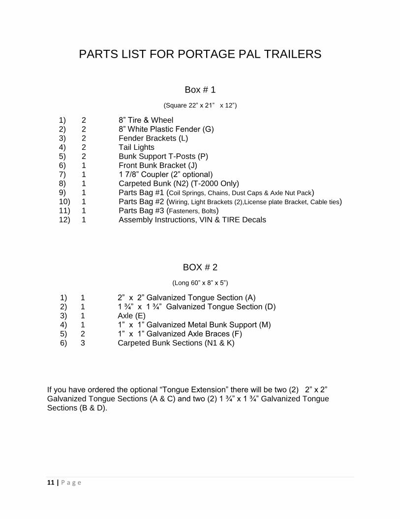
PARTS LIST FOR PORTAGE PAL TRAILERS
Box # 1
(Square 22” x 21” x 12”)
1) 2 8” Tire & Wheel 2) 2 8” White Plastic Fender (G) 3) 2 Fender Brackets (L) 4) 2 Tail Lights 5) 2 Bunk Support T-Posts (P) 6) 1 Front Bunk Bracket (J) 7) 1 1 7/8” Coupler (2” optional) 8) 1 Carpeted Bunk (N2) (T-2000 Only) 9) 1 Parts Bag #1 (Coil Springs, Chains, Dust Caps & Axle Nut Pack) 10) 1 Parts Bag #2 (Wiring, Light Brackets (2),License plate Bracket, Cable ties) 11) 1 Parts Bag #3 (Fasteners, Bolts) 12) 1 Assembly Instructions, VIN & TIRE Decals
BOX # 2
(Long 60” x 8” x 5”)
1) 1 2” x 2” Galvanized Tongue Section (A) 2) 1 1 ¾” x 1 ¾” Galvanized Tongue Section (D) 3) 1 Axle (E) 4) 1 1” x 1” Galvanized Metal Bunk Support (M) 5) 2 1” x 1” Galvanized Axle Braces (F) 6) 3 Carpeted Bunk Sections (N1 & K)
If you have ordered the optional “Tongue Extension” there will be two (2) 2” x 2” Galvanized Tongue Sections (A & C) and two (2) 1 ¾” x 1 ¾” Galvanized Tongue Sections (B & D).
12 | P a g e
ACCESSORIES
EZ LIFT HANDLE
If you have ordered an EZ Lift Handle there will be two (2) 3/8” x 3 ½” caps screws to be used to attach the EZ Lift handle, coupler and safety chains to the tongue section in place of the two (2) 3/8” x 3” cap screws.
2” COUPLER
If you have ordered a 2” coupler there will be two (2) ½” x 3 ½” cap screws to be used to attach the coupler and safety chains to the tongue section in place of the two (2) 3/8” x 3” cap screws.
2” COUPLER W/EZ LIFT HANDLE
If you have ordered a 2” coupler and an EZ lift handle there will be two (2) ½” x 4” cap screws to be used to attach them to the tongue section in place of the two (2) 3/8” x 3” cap screws.
SPARE TIRE CARRIER
If you have ordered a spare tire carrier there will be an extra castle nut, cotter pin and dust cap to hold the spare tire to the bracket. An axle washer is not used on the spare tire carrier.
TONGUE STAND
If you have ordered a tongue stand it needs to be mounted on and is designed to fit tongue section “A” which is the 2” x 2” square galvanized tube. It should be mounted 6” to 12” behind the coupler and so that when it is folded up it is pointing towards the rear of the trailer or backwards.
13 | P a g e
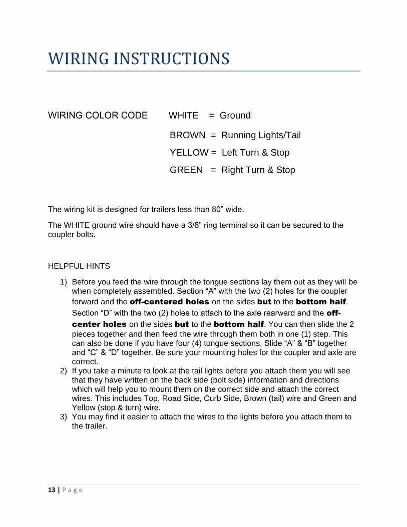
WIRING INSTRUCTIONS
WIRING COLOR CODE WHITE = Ground
BROWN = Running Lights/Tail
YELLOW = Left Turn & Stop
GREEN = Right Turn & Stop
The wiring kit is designed for trailers less than 80” wide.
The WHITE ground wire should have a 3/8” ring terminal so it can be secured to the coupler bolts.
HELPFUL HINTS
1) Before you feed the wire through the tongue sections lay them out as they will be when completely assembled. Section “A” with the two (2) holes for the coupler
forward and the off-centered holes on the sides but to the bottom half.
Section “D” with the two (2) holes to attach to the axle rearward and the off-
center holes on the sides but to the bottom half. You can then slide the 2
pieces together and then feed the wire through them both in one (1) step. This can also be done if you have four (4) tongue sections. Slide “A” & “B” together and “C” & “D” together. Be sure your mounting holes for the coupler and axle are correct.
2) If you take a minute to look at the tail lights before you attach them you will see that they have written on the back side (bolt side) information and directions which will help you to mount them on the correct side and attach the correct wires. This includes Top, Road Side, Curb Side, Brown (tail) wire and Green and Yellow (stop & turn) wire.
3) You may find it easier to attach the wires to the lights before you attach them to the trailer.
14 | P a g e
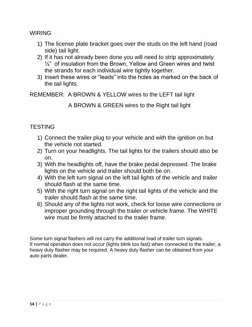
WIRING
1) The license plate bracket goes over the studs on the left hand (road side) tail light.
2) If it has not already been done you will need to strip approximately ½” of insulation from the Brown, Yellow and Green wires and twist the strands for each individual wire tightly together.
3) Insert these wires or “leads” into the holes as marked on the back of the tail lights.
REMEMBER: A BROWN & YELLOW wires to the LEFT tail light
A BROWN & GREEN wires to the Right tail light
TESTING
1) Connect the trailer plug to your vehicle and with the ignition on but the vehicle not started.
2) Turn on your headlights. The tail lights for the trailers should also be on.
3) With the headlights off, have the brake pedal depressed. The brake lights on the vehicle and trailer should both be on.
4) With the left turn signal on the left tail lights of the vehicle and trailer should flash at the same time.
5) With the right turn signal on the right tail lights of the vehicle and the trailer should flash at the same time.
6) Should any of the lights not work, check for loose wire connections or improper grounding through the trailer or vehicle frame. The WHITE wire must be firmly attached to the trailer frame.
Some turn signal flashers will not carry the additional load of trailer turn signals. If normal operation does not occur (lights blink too fast) when connected to the trailer, a heavy duty flasher may be required. A heavy duty flasher can be obtained from your auto parts dealer.