Embed Size (px)
Citation preview
INSTRUCTION MANUAL
One Jake Brown Road Old Bridge, NJ 08857-1000 USA
(800) 523-6049 • (732) 679-4000 • FAX: (732) 679-4353 www.blondertongue.com
©2013 Blonder Tongue Laboratories, Inc. All rights reserved. Specifications are subject to change without notice. Trademarks are the property of their respective owner.
BTPRO-1000 QAM/8VSB/Analog Signal AnalyzerModel Stock No. DescriptionBTPRO-1000 4230 QAM/8VSB/Analog Signal Analyzer 4230 RK Signal Analyzer with Pro:Idiom™ Key Recovery Option
Status Date Document No. Issue No. Author
Active May 7th 2014 651233900C 3 KK
Obsolete July 25, 2013 651233900B 2 KK
Obsolete July 10, 2013 651233900A 1 KK
2 BTPRO-1000 Instruction Manual
We recommend that you write the following information in the spaces provided below.
The information contained herein is subject to change without notice. Revisions may be issued to advise of such changes and/or additions.
Correspondence regarding this publication should be addressed directly to:
Blonder Tongue Laboratories, Inc.
One Jake Brown Road
Old Bridge, NJ 08857 USA
Document Number: 651233900C
Printed in the United States of America.
All product names, trade names, or corporate names mentioned in this document are acknowledged to be the proprietary property of the registered owners.
This product incorporates copyright protection technology that is protected by U.S. patents and other intellectual property rights. Reverse engineering or disassembly is prohibited.
Purchase Location Name:
Purchase Location Telephone Number:
BTPRO-1000 Serial Number:
3BTPRO-1000 Instruction Manual
Table of Contents
SECTION 1 – GENERAL & SAFETY INSTRUCTIONS ........................................................................................................................5
SECTION 2 – PRODUCT SUMMARY ................................................................................................................................................72.1 REVISION HISTORY & REASON ......................................................................................................................................................72.2 PRODUCT APPLICATION & DESCRIPTION .....................................................................................................................................72.3 PRODUCT SPECIFICATION .............................................................................................................................................................9
SECTION 3 – INSTALLATION & POWER-UP ...................................................................................................................................103.1 UNPACKING .................................................................................................................................................................................103.2 TURNING THE METER ON ............................................................................................................................................................103.3 TURNING THE METER OFF ...........................................................................................................................................................103.4 CHECK THE BATTERY CHARGE STATUS .........................................................................................................................................103.5 STANDARD NAVIGATION MODE ..................................................................................................................................................11
SECTION 4 – METER CONFIGURATION ..........................................................................................................................................124.1 METER MAIN SETUP ....................................................................................................................................................................12 4.1.1 BATTERY SAVING - SELF POWER OFF (TIMER OFF) .........................................................................................................12 4.1.2 FIELD AND CHANNEL POWER MEASUREMENT UNIT (UNIT) .........................................................................................12 4.1.3 LANGUAGE ......................................................................................................................................................................12 4.1.4 KEYS BEEP VOLUME SETUP .............................................................................................................................................12 4.1.5 DISPLAY BACKLIGHT (DISP. LIGHT) ..................................................................................................................................12 4.1.6 LCD BACKLIGHT BRIGHTNESS ADJUSTMENT ..................................................................................................................12
SECTION 5 – SIGNAL TUNING ........................................................................................................................................................135.1 NAVIGATE INTO THE SELECTED MEMORY PLAN .........................................................................................................................13 5.1.1 SURFING THE CHANNELS ................................................................................................................................................13 5.1.2 MODIFY AND FINE-TUNE THE RECEPTION FREQUENCY .................................................................................................13 5.1.3 MODIFY THE SIGNAL TYPE ..............................................................................................................................................13 5.1.4 MODIFY THE AUDIO FREQUENCY (ANALOG SIGNALS) ...................................................................................................14 5.1.5 MODIFY THE QAM MODULATION TYPE (QAM SIGNALS) ...............................................................................................14 5.1.6 MODIFY THE SYMBOL RATE (QAM SIGNALS) .................................................................................................................14
SECTION 6 – PERFORMING MEASUREMENTS: MEAS ...................................................................................................................156.1 THE SELECTED CHANNEL CARRIER ON A DIGITAL CATV SIGNAL (QAM) .....................................................................................15 6.1.1 CHANNEL POWER MEASUREMENT ................................................................................................................................15 6.1.2 NOISE MARGIN, QUALITY TEST, MER AND BLOCK ERROR MEASUREMENTS .................................................................15 6.1.3 BER MEASUREMENT BEFORE AND AFTER ERROR CORRECTION ...................................................................................16 6.1.4 CARRIERS CONSTELLATION AND QAM PARAMETERS DISPLAY .......................................................................................16 6.1.4a ZOOMING THE CONSTELLATION IN/OUT ............................................................................................................16 6.1.5 SPECTRUM ANALYSIS OF THE TUNED CHANNEL ............................................................................................................166.2 THE SELECTED CHANNEL CARRIER ON AN ANALOG TV/CATV SIGNAL........................................................................................17 6.2.1 VIDEO SIGNAL PEAK LEVEL MEASUREMENT ..................................................................................................................17 6.2.2 VIDEO VS. AUDIO PEAK LEVEL RATIO AND SIGNAL TO NOISE RATIO .............................................................................17 6.2.3 SPECTRUM ANALYSIS OF THE TUNED CHANNEL ............................................................................................................176.3 FM AUDIO MEASUREMENT (INCLUDED FM RADIO 87.5 - 108.00 MHZ) ....................................................................................17 6.3.1 AUDIO LEVEL MEASUREMENT ........................................................................................................................................17 6.3.2 SPECTRUM ANALYSIS OF THE TUNED CHANNEL ............................................................................................................17
SECTION 7 – SPECTRUM ANALYZER MODE ...................................................................................................................................187.1 SURFING THE CHANNELS .............................................................................................................................................................187.2 MOVING THE MARKER (FREQUENCY VALUE) ..............................................................................................................................197.3 EDITING THE SIGNAL LEVEL END OF SCALE .................................................................................................................................197.4 EDITING THE SPAN VALUE............................................................................................................................................................19
4 BTPRO-1000 Instruction Manual
7.5 FULL BAND MAPPING ..................................................................................................................................................................19 7.5.1 WIDE BAND MAPPING DISPLAY CONFIGURATION ..........................................................................................................19 7.5.1a EDITING THE DB/DIV VALUE ................................................................................................................................20 7.5.1b EDITING THE END-OF-SCALE VALUE ....................................................................................................................20 7.5.1c ZOOMING THE CONSTELLATION IN/OUT .............................................................................................................20 7.5.2 SIGNAL LEVEL COMPARISON (TILT) BETWEEN TWO USER-DEFINED CHANNELS .............................................................20
SECTION 8 – CABLE SYSTEM MEASUREMENTS .............................................................................................................................218.1 VOLTMETER MODE (AC MEASURE AT RF TEST POINT) ...............................................................................................................218.2 CABLE LEAKAGE SETUP ................................................................................................................................................................21 8.2.1 AREA AND MEASUREMENT UNIT STANDARD SETUP .....................................................................................................21 8.2.2 ANTENNA TYPE SETUP ....................................................................................................................................................22 8.2.3 ANTENNA FACTOR SETUP ...............................................................................................................................................22 8.2.4 DISTANCE SETUP .............................................................................................................................................................22 8.2.5 THRESHOLD SETUP .........................................................................................................................................................228.3 CABLE LEAKAGE MEASUREMENT ................................................................................................................................................228.4 INGRESS MODE SETUP (MEASUREMENTS ON THE FREQUENCY RANGE 4 - 66 MHZ) ...............................................................23 8.4.1 INGRESS MODE MEASUREMENTS ..................................................................................................................................23 8.4.1a MOVING THE MARKER (FREQUENCY VALUE) ......................................................................................................24 8.4.1b EDITING THE SWEEP TIME ...................................................................................................................................24 8.4.1c EDITING THE SIGNAL LEVEL END OF SCALE .........................................................................................................24 8.4.1d MAXHOLD ............................................................................................................................................................248.5 PRO:IDIOM™ RECOVERY OPTION ................................................................................................................................................24 8.5.1 PLAN SETUP.....................................................................................................................................................................24 8.5.2 CHANNEL SETUP .............................................................................................................................................................24 8.5.3 MODE SETUP ...................................................................................................................................................................24 8.5.4 SET PARAMETERS? ..........................................................................................................................................................24 8.5.5 COMMAND SETUP ..........................................................................................................................................................24 8.5.6 SEND COMMAND ............................................................................................................................................................24 8.5.7 STATUS .............................................................................................................................................................................24
SECTION 9 – CREATING MEMORY PLANS ......................................................................................................................................259.1 CREATING A MEMORY PLAN BY AUTO SEEK & STORE OF RECEIVABLE SIGNALS ........................................................................25 9.1.1 SELECT A SOURCE MEMORY PLAN .................................................................................................................................25 9.1.2 SELECT A TARGET AUTOMEMORY PLAN .........................................................................................................................25 9.1.3 SELECT THE SIGNAL TYPE ................................................................................................................................................25 9.1.4 ANALOG SIGNALS: VIDEO SIGNAL LEVEL THRESHOLD SETUP ........................................................................................26 9.1.5 DIGITAL SIGNALS: CHANNEL POWER LEVEL THRESHOLD SETUP ...................................................................................26 9.1.6 SEEK&STORE START .........................................................................................................................................................269.2 MANUALLY CREATING A MEMORY PLAN .....................................................................................................................................26 9.2.1 SELECT A SOURCE MEMORY PLAN .................................................................................................................................26 9.2.2 SELECT A TARGET AUTOMEMORY PLAN .........................................................................................................................26 9.2.3 CREATE A BRAND NEW MEMORY PLAN .........................................................................................................................27 9.2.3a CHANNEL SELECTION ...........................................................................................................................................27 9.2.3b DISABLE/SPECIFY STANDARD ...............................................................................................................................27 9.2.3c FREQUENCY ..........................................................................................................................................................27 9.2.3d SYMBOL RATE (DIGITAL SIGNALS ONLY) ..............................................................................................................279.3 DELETING A MEMORY PLAN ........................................................................................................................................................28 9.3.1 DELETING A MEMORY CHANNEL PLAN ..........................................................................................................................28 9.3.2 DELETING A LOGGER FILE (LOGGER MEMORY PLAN) ....................................................................................................28
SECTION 10 – AUTO MEAS&STORE ON THE CHANNELS INCLUDED IN A CUSTOM MEMORY PLAN (DATA LOGGER) ...............2910.1 AUTO MEAS&STORE ..................................................................................................................................................................2910.2 RECALL A PREVIOUSLY STORED LOGGER MEMORY PLAN .........................................................................................................30
SECTION 11 – MAINTAINING THE METER .....................................................................................................................................3111.1 CLEANING THE METER ...............................................................................................................................................................3111.2 MAINTENANCE AND CARE OF THE METER ...............................................................................................................................31
5BTPRO-1000 Instruction Manual
Safety Instructions
➥ Elevated Operating Ambient - If installed in a closed or multi-unit rack assembly, the operating ambient temperature of the rack environment may be greater than room ambient. Therefore, consideration should be given to installing the equipment in an environment compatible with the maximum ambient temperature per Section 2.3.
➥ Reduced Air Flow - Installation of the equipment in a rack should be such that the amount of air flow required for safe operation of the equipment is not compromised.
➥ Mechanical Loading - Mounting of the equipment in the rack should be such that a hazardous condition is not achieved due to uneven mechanical loading.
➥ Circuit Overloading - Consideration should be given to the connection of the equipment to the supply circuit and the effect that overloading of the circuits might have on overcurrent protection and supply wiring. Appropriate consideration of equipment nameplate ratings should be used when addressing this concern.
➥ Reliable Earthing - Reliable earthing of rack-mounted equipment should be maintained. Particular attention should be given to supply connections other than direct connections to the branch circuit (e.g. use of power strips).
➥ Read all safety and operating instructions before you operate the unit.
➥ Retain all safety and operating instructions for future reference.
➥ Heed all warnings on the unit and in the safety and operating instructions.
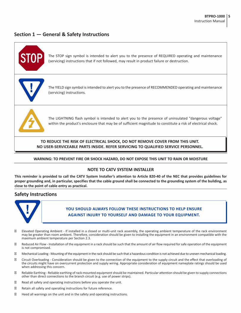
WARNING: TO PREVENT FIRE OR SHOCK HAZARD, DO NOT EXPOSE THIS UNIT TO RAIN OR MOISTURE
NOTE TO CATV SYSTEM INSTALLERThis reminder is provided to call the CATV System Installer’s attention to Article 820-40 of the NEC that provides guidelines for proper grounding and, in particular, specifies that the cable ground shall be connected to the grounding system of the building, as close to the point of cable entry as practical.
The STOP sign symbol is intended to alert you to the presence of REQUIRED operating and maintenance (servicing) instructions that if not followed, may result in product failure or destruction.
TO REDUCE THE RISK OF ELECTRICAL SHOCK, DO NOT REMOVE COVER FROM THIS UNIT. NO USER-SERVICEABLE PARTS INSIDE. REFER SERVICING TO QUALIFIED SERVICE PERSONNEL.
Section 1 — General & Safety Instructions
The YIELD sign symbol is intended to alert you to the presence of RECOMMENDED operating and maintenance (servicing) instructions.
The LIGHTNING flash symbol is intended to alert you to the presence of uninsulated "dangerous voltage" within the product's enclosure that may be of sufficient magnitude to constitute a risk of electrical shock.
YOU SHOULD ALWAYS FOLLOW THESE INSTRUCTIONS TO HELP ENSUREAGAINST INJURY TO YOURSELF AND DAMAGE TO YOUR EQUIPMENT.
6 BTPRO-1000 Instruction Manual
Safety Instructions - continued➥ Follow all installation, operating, and use instructions.
➥ Unplug the unit from the AC power outlet before cleaning. Use only a damp cloth for cleaning the exterior of the unit.
➥ Do not use accessories or attachments not recommended by Blonder Tongue, as they may cause hazards, and will void the warranty.
➥ Do not operate the unit in high-humidity areas, or expose it to water or moisture.
➥ Do not place the unit on an unstable cart, stand, tripod, bracket, or table. The unit may fall, causing serious personal injury and damage to the unit. Install the unit only in a mounting rack designed for 19” rack-mounted equipment.
➥ Do not block or cover slots and openings in the unit. These are provided for ventilation and protection from overheating. Never place the unit near or over a radiator or heat register. Do not place the unit in an enclosure such as a cabinet without proper ventilation. Do not mount equipment in the rack space directly above or below the unit.
➥ Operate the unit using only the type of power source indicated on the marking label. Unplug the unit power cord by gripping the plug, not the cord.
➥ The unit is equipped with a three-wire ground-type plug. This plug will fit only into a ground-type power outlet. If you are unable to insert the plug into the outlet, contact an electrician to replace the outlet. Do not defeat the safety purpose of the ground-type plug.
➥ Route power supply cords so that they are not likely to be walked on or pinched by items placed upon or against them. Pay particular attention to cords at plugs, convenience receptacles, and the point where they exit from the unit.
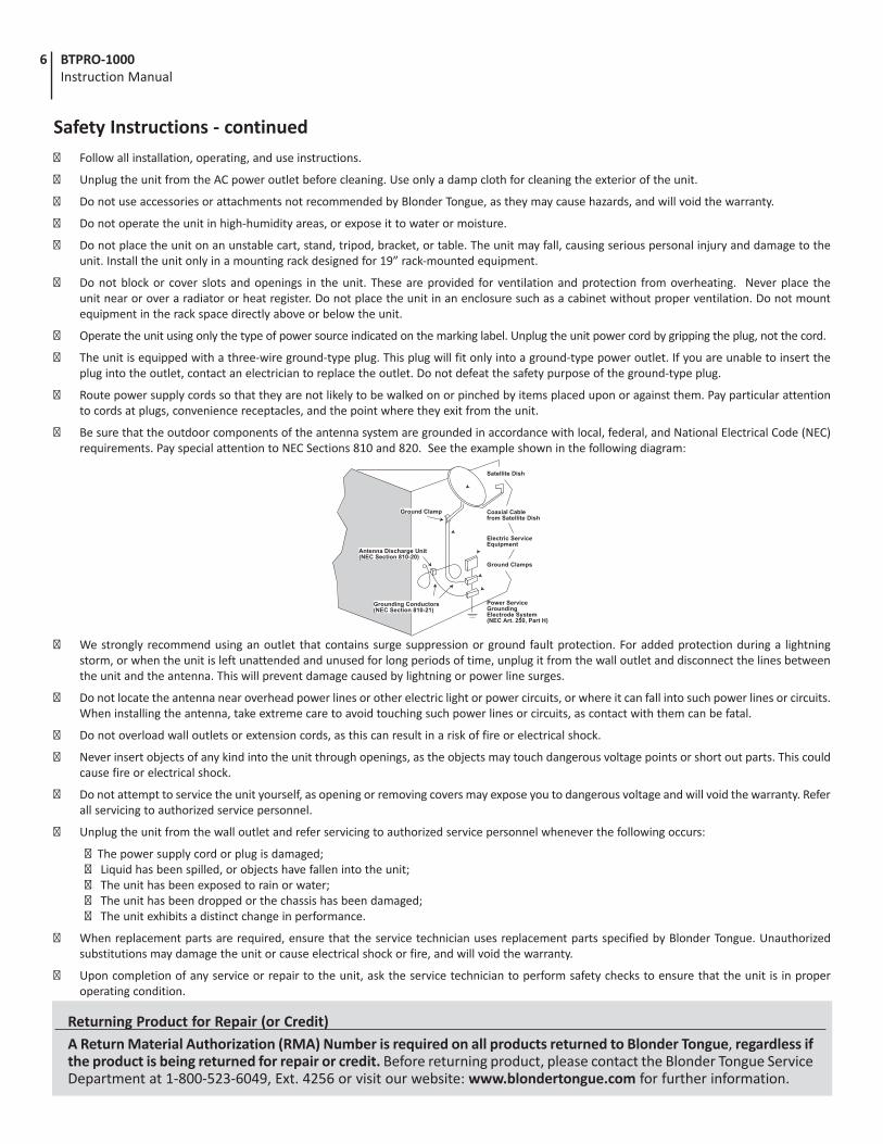
➥ Be sure that the outdoor components of the antenna system are grounded in accordance with local, federal, and National Electrical Code (NEC) requirements. Pay special attention to NEC Sections 810 and 820. See the example shown in the following diagram:
➥ We strongly recommend using an outlet that contains surge suppression or ground fault protection. For added protection during a lightning storm, or when the unit is left unattended and unused for long periods of time, unplug it from the wall outlet and disconnect the lines between the unit and the antenna. This will prevent damage caused by lightning or power line surges.
➥ Do not locate the antenna near overhead power lines or other electric light or power circuits, or where it can fall into such power lines or circuits. When installing the antenna, take extreme care to avoid touching such power lines or circuits, as contact with them can be fatal.
➥ Do not overload wall outlets or extension cords, as this can result in a risk of fire or electrical shock.
➥ Never insert objects of any kind into the unit through openings, as the objects may touch dangerous voltage points or short out parts. This could cause fire or electrical shock.
➥ Do not attempt to service the unit yourself, as opening or removing covers may expose you to dangerous voltage and will void the warranty. Refer all servicing to authorized service personnel.
➥ Unplug the unit from the wall outlet and refer servicing to authorized service personnel whenever the following occurs:
➥ The power supply cord or plug is damaged; ➥ Liquid has been spilled, or objects have fallen into the unit; ➥ The unit has been exposed to rain or water; ➥ The unit has been dropped or the chassis has been damaged; ➥ The unit exhibits a distinct change in performance.
➥ When replacement parts are required, ensure that the service technician uses replacement parts specified by Blonder Tongue. Unauthorized substitutions may damage the unit or cause electrical shock or fire, and will void the warranty.
➥ Upon completion of any service or repair to the unit, ask the service technician to perform safety checks to ensure that the unit is in proper operating condition.
Returning Product for Repair (or Credit)A Return Material Authorization (RMA) Number is required on all products returned to Blonder Tongue, regardless if the product is being returned for repair or credit. Before returning product, please contact the Blonder Tongue Service Department at 1-800-523-6049, Ext. 4256 or visit our website: www.blondertongue.com for further information.
7BTPRO-1000 Instruction Manual
Section 2 — Product Summary2.1 Revision History & Reason
This is the third issue of the Instruction Manual. Update for F/W Version 3.0 with additional test patterns in the Pro:Idiom™ Recovery Option (section 8.5).
The second issue of the Instruction Manual updated the Pro:Idiom™ Recovery Option section 8.5.
2.2 Product Application & Description
Application:
The BTPRO-1000 is a versatile CATV test instrument for measuring both digital and analog CATV and Broadcast TV signals. Robust and easy to use, BTPRO-1000 provides hours of operating time from its high capacity battery. The instrument comes complete with a soft carrying case, AC main and automotive chargers.
An optional Pro:Idiom™ Key Recovery feature is available for Hospitality applications that employ Pro:Idiom™ television sets. The option consists of a built-in frequency agile QAM modulator that connects directly to an affected Pro:Idiom™ TV to provide new encryption key information.
Features:• QAM/8VSB/NTSC Measurements• Extended frequency range of 4-1000 MHz• MER, aBER, bBER, Noise Margin and Level/Power measurements plus Spectrum Analysis• Automatic quality analysis: FAIL-MARGINAL-PASS• Auto Seek & Store Function - an essential feature for creating custom memory channel plans. Scans receivable signals,
determines signal type (QAM,8VSB or analog) and stores only those channels having signal levels above user defined values• Ingress and Leakage Modes• Data Logger Function: Steps through each channel in the “Active” memory plan and stores all related measurements• Alpha-numeric keypad• Optional TV Key Recovery for Hospitality Pro:Idiom™ systems
8 BTPRO-1000 Instruction Manual
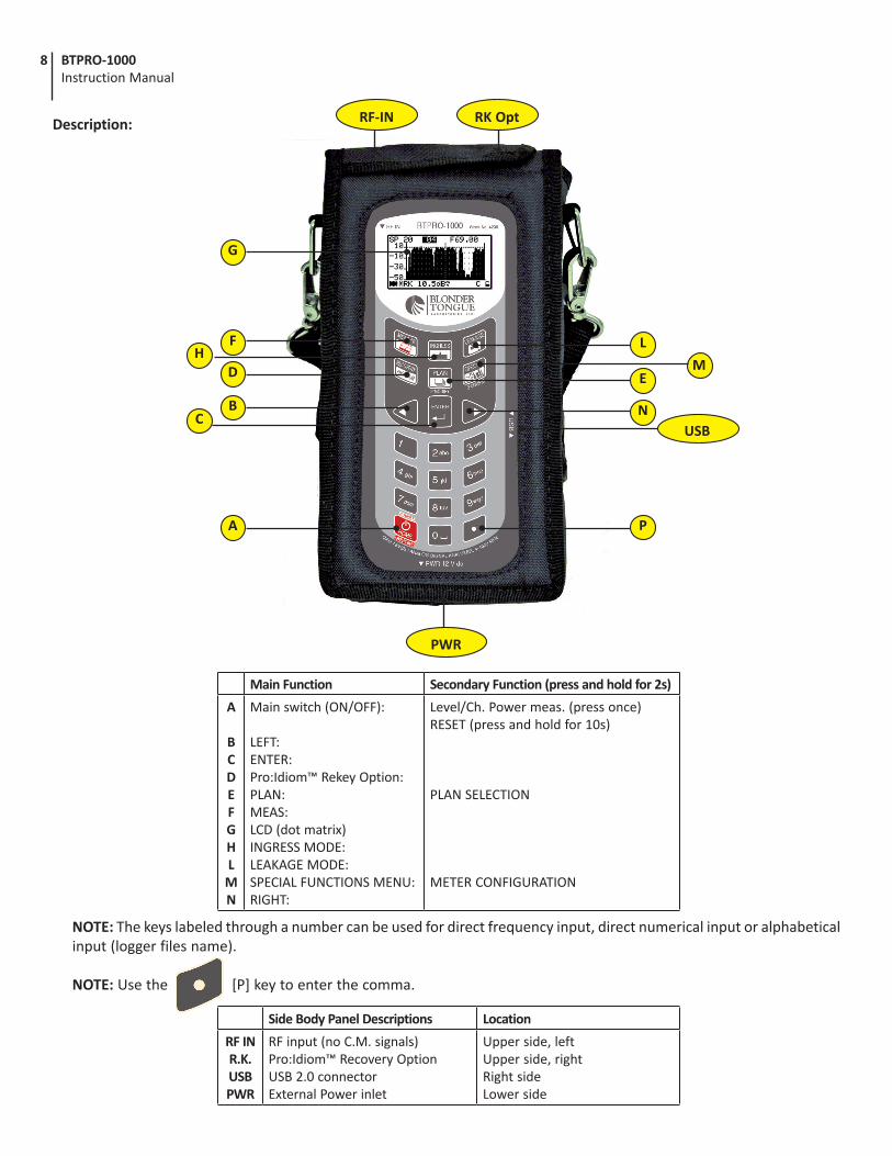
Description:
A
E
G
Main Function Secondary Function (press and hold for 2s)
A
BC D E F G H L M N
Main switch (ON/OFF):
LEFT:ENTER:Pro:Idiom™ Rekey Option:PLAN:MEAS:LCD (dot matrix)INGRESS MODE:LEAKAGE MODE:SPECIAL FUNCTIONS MENU:RIGHT:
Level/Ch. Power meas. (press once) RESET (press and hold for 10s)
PLAN SELECTION
METER CONFIGURATION
NOTE: The keys labeled through a number can be used for direct frequency input, direct numerical input or alphabetical input (logger files name).
NOTE: Use the [P] key to enter the comma.
Side Body Panel Descriptions Location
RF INR.K.USBPWR
RF input (no C.M. signals)Pro:Idiom™ Recovery OptionUSB 2.0 connectorExternal Power inlet
Upper side, leftUpper side, rightRight sideLower side
HL
M
N
RF-IN RK Opt
PWR
USB
F
D
BC
P
9BTPRO-1000 Instruction Manual
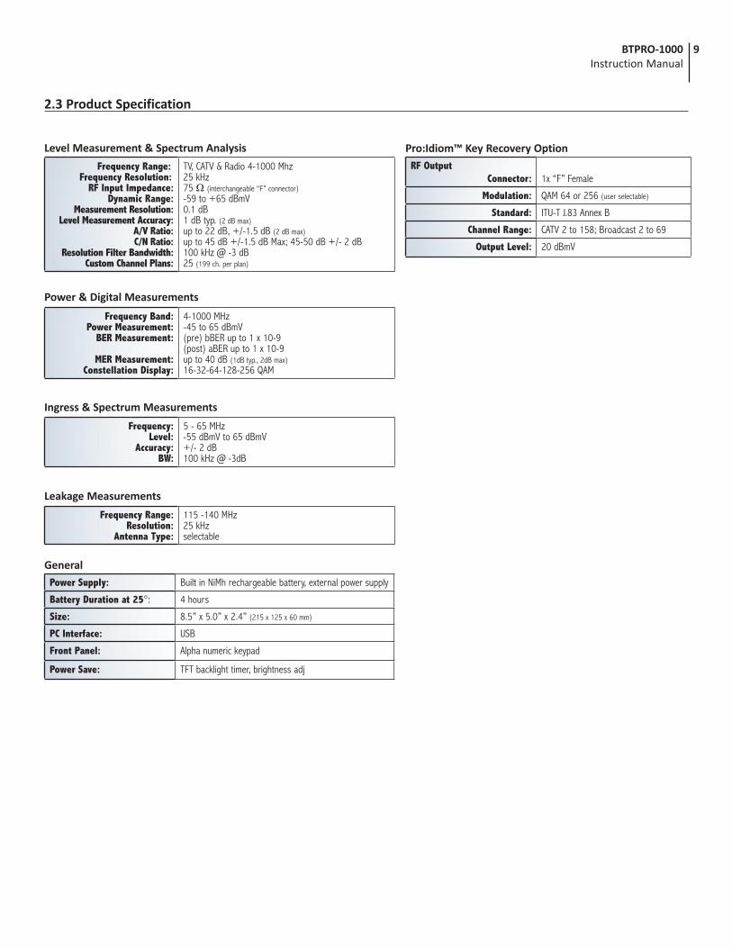
2.3 Product Specification
Level Measurement & Spectrum Analysis
Frequency Range: Frequency Resolution:
RF Input Impedance:Dynamic Range:
Measurement Resolution:Level Measurement Accuracy:
A/V Ratio:C/N Ratio:
Resolution Filter Bandwidth:Custom Channel Plans:
TV, CATV & Radio 4-1000 Mhz25 kHz75 Ω (interchangeable “F” connector)-59 to +65 dBmV0.1 dB1 dB typ. (2 dB max)up to 22 dB, +/-1.5 dB (2 dB max)up to 45 dB +/-1.5 dB Max; 45-50 dB +/- 2 dB100 kHz @ -3 dB25 (199 ch. per plan)
GeneralPower Supply: Built in NiMh rechargeable battery, external power supply
Battery Duration at 25°: 4 hours
Size: 8.5” x 5.0” x 2.4” (215 x 125 x 60 mm)
PC Interface: USB
Front Panel: Alpha numeric keypad
Power Save: TFT backlight timer, brightness adj
Power & Digital Measurements
Frequency Band:Power Measurement:
BER Measurement:
MER Measurement:Constellation Display:
4-1000 MHz-45 to 65 dBmV(pre) bBER up to 1 x 10⁻⁹(post) aBER up to 1 x 10⁻⁹up to 40 dB (1dB typ., 2dB max)16-32-64-128-256 QAM
Frequency:Level:
Accuracy:BW:
5 - 65 MHz-55 dBmV to 65 dBmV+/- 2 dB100 kHz @ -3dB
Ingress & Spectrum Measurements
Frequency Range:Resolution:
Antenna Type:
115 -140 MHz25 kHzselectable
Leakage Measurements
Pro:Idiom™ Key Recovery OptionRF Output
Connector: 1x “F” Female
Modulation: QAM 64 or 256 (user selectable)
Standard: ITU-T J.83 Annex B
Channel Range: CATV 2 to 158; Broadcast 2 to 69
Output Level: 20 dBmV
10 BTPRO-1000 Instruction Manual
Section 3 – Installation & Power-up3.1 Unpacking
You will find the following items in the box:
• BTPRO-1000 Meter (QTY=1)
• AC Adapter (QTY=1)
• 12 V Automotive Adapter (QTY=1)
• USB 2.0 Cable (QTY=1)
• F-81 Connector (QTY=2)
• Soft Carry Case and Strap (QTY=1)
3.2 Turning the Meter On
Press and release the HOME [A] key.
3.3 Turning the Meter Off
Press and hold for 2s the HOME [A] key.
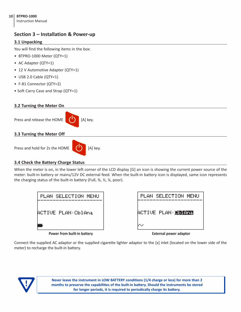
3.4 Check the Battery Charge Status
When the meter is on, in the lower left corner of the LCD display [G] an icon is showing the current power source of the meter: built-in battery or mains/12V DC external feed. When the built-in battery icon is displayed, same icon represents the charging status of the built-in battery (Full, ¾, ½, ¼, poor).
Connect the supplied AC adaptor or the supplied cigarette lighter adaptor to the [x] inlet (located on the lower side of the meter) to recharge the built-in battery.
Power from built-in battery External power adaptor
Never leave the instrument in LOW BATTERY conditions (1/4 charge or less) for more than 2 months to preserve the capabilities of the built-in battery. Should the instruments be stored
for longer periods, it is required to periodically charge its battery.
11BTPRO-1000 Instruction Manual
3.5 Standard Navigation Mode
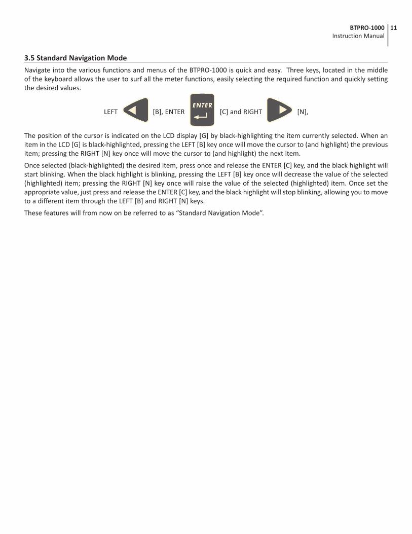
Navigate into the various functions and menus of the BTPRO-1000 is quick and easy. Three keys, located in the middle of the keyboard allows the user to surf all the meter functions, easily selecting the required function and quickly setting the desired values.
LEFT [B], ENTER [C] and RIGHT [N],
The position of the cursor is indicated on the LCD display [G] by black-highlighting the item currently selected. When an item in the LCD [G] is black-highlighted, pressing the LEFT [B] key once will move the cursor to (and highlight) the previous item; pressing the RIGHT [N] key once will move the cursor to (and highlight) the next item.
Once selected (black-highlighted) the desired item, press once and release the ENTER [C] key, and the black highlight will start blinking. When the black highlight is blinking, pressing the LEFT [B] key once will decrease the value of the selected (highlighted) item; pressing the RIGHT [N] key once will raise the value of the selected (highlighted) item. Once set the appropriate value, just press and release the ENTER [C] key, and the black highlight will stop blinking, allowing you to move to a different item through the LEFT [B] and RIGHT [N] keys.
These features will from now on be referred to as “Standard Navigation Mode”.
12 BTPRO-1000 Instruction Manual
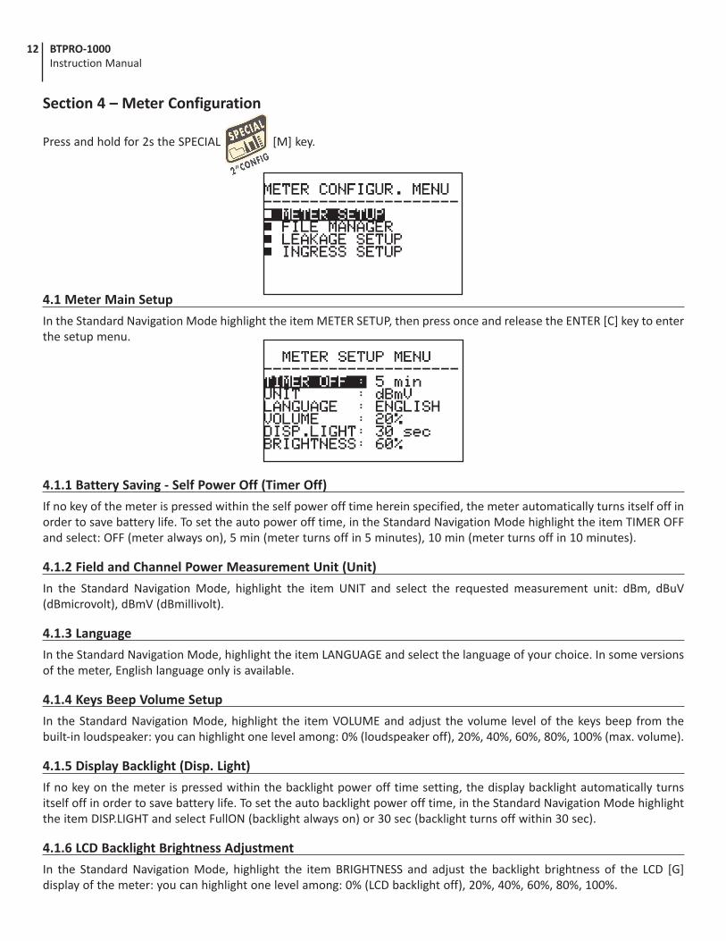
Section 4 – Meter Configuration
Press and hold for 2s the SPECIAL [M] key.
4.1 Meter Main Setup
In the Standard Navigation Mode highlight the item METER SETUP, then press once and release the ENTER [C] key to enter the setup menu.
4.1.1 Battery Saving - Self Power Off (Timer Off)
If no key of the meter is pressed within the self power off time herein specified, the meter automatically turns itself off in order to save battery life. To set the auto power off time, in the Standard Navigation Mode highlight the item TIMER OFF and select: OFF (meter always on), 5 min (meter turns off in 5 minutes), 10 min (meter turns off in 10 minutes).
4.1.2 Field and Channel Power Measurement Unit (Unit)
In the Standard Navigation Mode, highlight the item UNIT and select the requested measurement unit: dBm, dBuV (dBmicrovolt), dBmV (dBmillivolt).
4.1.3 Language
In the Standard Navigation Mode, highlight the item LANGUAGE and select the language of your choice. In some versions of the meter, English language only is available.
4.1.4 Keys Beep Volume Setup
In the Standard Navigation Mode, highlight the item VOLUME and adjust the volume level of the keys beep from the built-in loudspeaker: you can highlight one level among: 0% (loudspeaker off), 20%, 40%, 60%, 80%, 100% (max. volume).
4.1.5 Display Backlight (Disp. Light)
If no key on the meter is pressed within the backlight power off time setting, the display backlight automatically turns itself off in order to save battery life. To set the auto backlight power off time, in the Standard Navigation Mode highlight the item DISP.LIGHT and select FullON (backlight always on) or 30 sec (backlight turns off within 30 sec).
4.1.6 LCD Backlight Brightness Adjustment
In the Standard Navigation Mode, highlight the item BRIGHTNESS and adjust the backlight brightness of the LCD [G] display of the meter: you can highlight one level among: 0% (LCD backlight off), 20%, 40%, 60%, 80%, 100%.
13BTPRO-1000 Instruction Manual
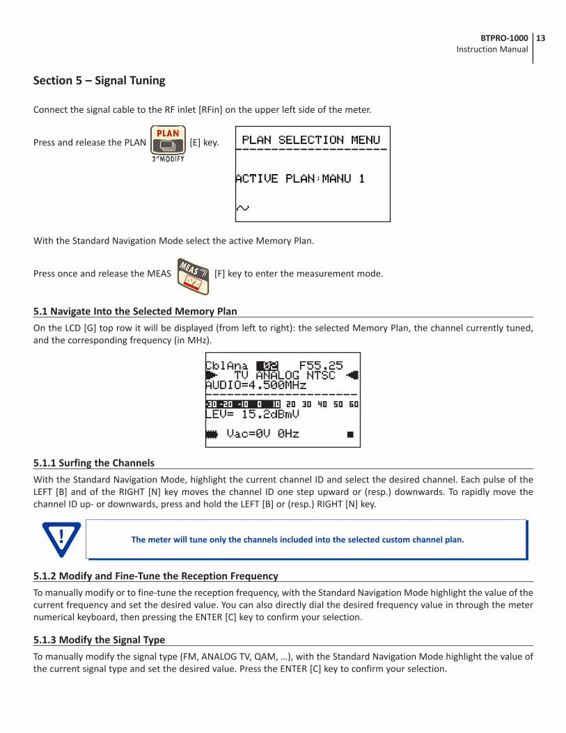
Section 5 – Signal Tuning
Connect the signal cable to the RF inlet [RFin] on the upper left side of the meter.
Press and release the PLAN [E] key.
With the Standard Navigation Mode select the active Memory Plan.
Press once and release the MEAS [F] key to enter the measurement mode.
5.1 Navigate Into the Selected Memory Plan
On the LCD [G] top row it will be displayed (from left to right): the selected Memory Plan, the channel currently tuned, and the corresponding frequency (in MHz).
5.1.1 Surfing the Channels
With the Standard Navigation Mode, highlight the current channel ID and select the desired channel. Each pulse of the LEFT [B] and of the RIGHT [N] key moves the channel ID one step upward or (resp.) downwards. To rapidly move the channel ID up- or downwards, press and hold the LEFT [B] or (resp.) RIGHT [N] key.
5.1.2 Modify and Fine-Tune the Reception Frequency
To manually modify or to fine-tune the reception frequency, with the Standard Navigation Mode highlight the value of the current frequency and set the desired value. You can also directly dial the desired frequency value in through the meter numerical keyboard, then pressing the ENTER [C] key to confirm your selection.
5.1.3 Modify the Signal Type
To manually modify the signal type (FM, ANALOG TV, QAM, …), with the Standard Navigation Mode highlight the value of the current signal type and set the desired value. Press the ENTER [C] key to confirm your selection.
The meter will tune only the channels included into the selected custom channel plan.
14 BTPRO-1000 Instruction Manual
5.1.4 Modify the Audio Frequency (Analog Signals)
To manually modify the audio carrier frequency, with the Standard Navigation Mode highlight the value of the current audio carrier frequency and set the desired value. Press the ENTER [C] key to confirm your selection.
5.1.5 Modify the QAM Modulation Type (QAM Signals)
To manually modify the QAM modulation type, with the Standard Navigation Mode highlight the value of the current QAM type and set the desired value. Press the ENTER [C] key to confirm your selection.
5.1.6 Modify the Symbol Rate (QAM Signals)
To manually modify the Symbol Rate, with the Standard Navigation Mode highlight the value of the current S.R. and set the desired value. Press the ENTER [C] key to confirm your selection.
15BTPRO-1000 Instruction Manual
Section 6 – Performing Measurements: MEAS
6.1 The Selected Channel Carrier On A Digital CATV Signal (QAM)
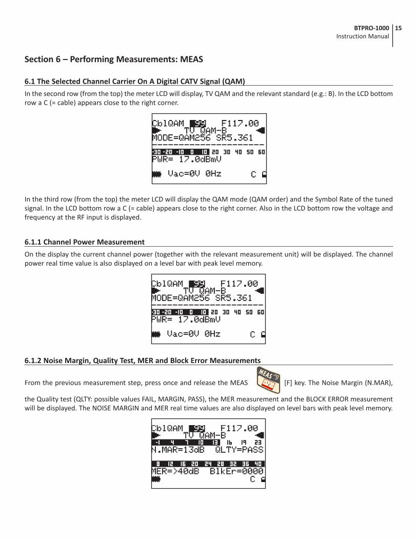
In the second row (from the top) the meter LCD will display, TV QAM and the relevant standard (e.g.: B). In the LCD bottom row a C (= cable) appears close to the right corner.
In the third row (from the top) the meter LCD will display the QAM mode (QAM order) and the Symbol Rate of the tuned signal. In the LCD bottom row a C (= cable) appears close to the right corner. Also in the LCD bottom row the voltage and frequency at the RF input is displayed.
6.1.1 Channel Power Measurement
On the display the current channel power (together with the relevant measurement unit) will be displayed. The channel power real time value is also displayed on a level bar with peak level memory.
6.1.2 Noise Margin, Quality Test, MER and Block Error Measurements
From the previous measurement step, press once and release the MEAS [F] key. The Noise Margin (N.MAR),
the Quality test (QLTY: possible values FAIL, MARGIN, PASS), the MER measurement and the BLOCK ERROR measurement will be displayed. The NOISE MARGIN and MER real time values are also displayed on level bars with peak level memory.
16 BTPRO-1000 Instruction Manual
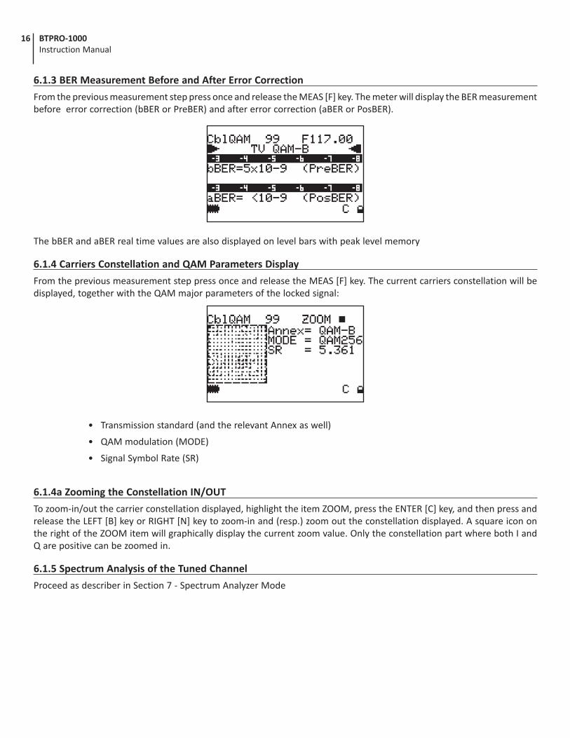
6.1.3 BER Measurement Before and After Error Correction
From the previous measurement step press once and release the MEAS [F] key. The meter will display the BER measurement before error correction (bBER or PreBER) and after error correction (aBER or PosBER).
The bBER and aBER real time values are also displayed on level bars with peak level memory
6.1.4 Carriers Constellation and QAM Parameters Display
From the previous measurement step press once and release the MEAS [F] key. The current carriers constellation will be displayed, together with the QAM major parameters of the locked signal:
• Transmission standard (and the relevant Annex as well)
• QAM modulation (MODE)
• Signal Symbol Rate (SR)
6.1.4a Zooming the Constellation IN/OUT
To zoom-in/out the carrier constellation displayed, highlight the item ZOOM, press the ENTER [C] key, and then press and release the LEFT [B] key or RIGHT [N] key to zoom-in and (resp.) zoom out the constellation displayed. A square icon on the right of the ZOOM item will graphically display the current zoom value. Only the constellation part where both I and Q are positive can be zoomed in.
6.1.5 Spectrum Analysis of the Tuned Channel
Proceed as describer in Section 7 - Spectrum Analyzer Mode
17BTPRO-1000 Instruction Manual
6.2 The Selected Channel Carrier On an Analog TV/CATV Signal
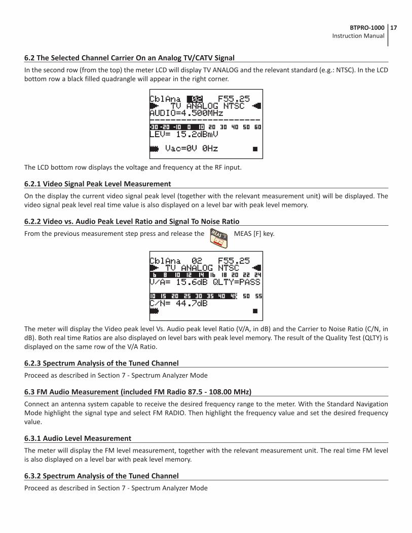
In the second row (from the top) the meter LCD will display TV ANALOG and the relevant standard (e.g.: NTSC). In the LCD bottom row a black filled quadrangle will appear in the right corner.
The LCD bottom row displays the voltage and frequency at the RF input.
6.2.1 Video Signal Peak Level Measurement
On the display the current video signal peak level (together with the relevant measurement unit) will be displayed. The video signal peak level real time value is also displayed on a level bar with peak level memory.
6.2.2 Video vs. Audio Peak Level Ratio and Signal To Noise Ratio
From the previous measurement step press and release the MEAS [F] key.
The meter will display the Video peak level Vs. Audio peak level Ratio (V/A, in dB) and the Carrier to Noise Ratio (C/N, in dB). Both real time Ratios are also displayed on level bars with peak level memory. The result of the Quality Test (QLTY) is displayed on the same row of the V/A Ratio.
6.2.3 Spectrum Analysis of the Tuned Channel
Proceed as described in Section 7 - Spectrum Analyzer Mode
6.3 FM Audio Measurement (included FM Radio 87.5 - 108.00 MHz)
Connect an antenna system capable to receive the desired frequency range to the meter. With the Standard Navigation Mode highlight the signal type and select FM RADIO. Then highlight the frequency value and set the desired frequency value.
6.3.1 Audio Level Measurement
The meter will display the FM level measurement, together with the relevant measurement unit. The real time FM level is also displayed on a level bar with peak level memory.
6.3.2 Spectrum Analysis of the Tuned Channel
Proceed as described in Section 7 - Spectrum Analyzer Mode
18 BTPRO-1000 Instruction Manual
Section 7 – Spectrum Analyzer Mode
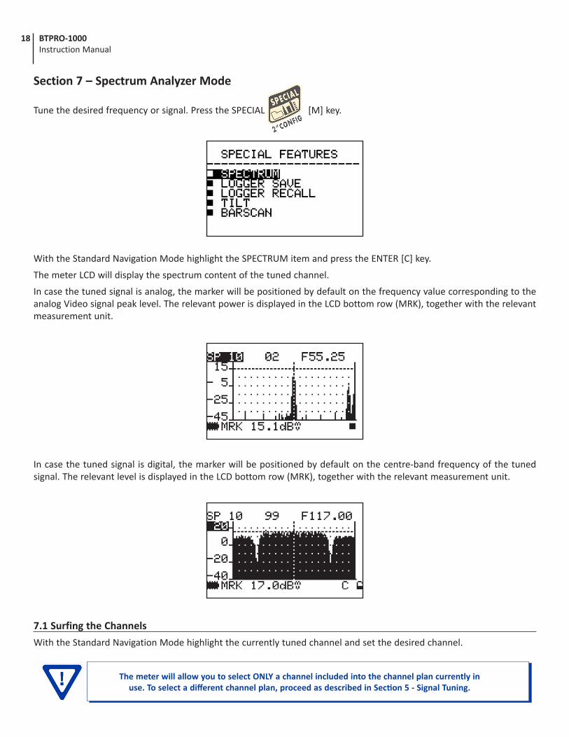
Tune the desired frequency or signal. Press the SPECIAL [M] key.
With the Standard Navigation Mode highlight the SPECTRUM item and press the ENTER [C] key.
The meter LCD will display the spectrum content of the tuned channel.
In case the tuned signal is analog, the marker will be positioned by default on the frequency value corresponding to the analog Video signal peak level. The relevant power is displayed in the LCD bottom row (MRK), together with the relevant measurement unit.
In case the tuned signal is digital, the marker will be positioned by default on the centre-band frequency of the tuned signal. The relevant level is displayed in the LCD bottom row (MRK), together with the relevant measurement unit.
7.1 Surfing the Channels
With the Standard Navigation Mode highlight the currently tuned channel and set the desired channel.
The meter will allow you to select ONLY a channel included into the channel plan currently in use. To select a different channel plan, proceed as described in Section 5 - Signal Tuning.
19BTPRO-1000 Instruction Manual
7.2 Moving the Marker (Frequency Value)
With the Standard Navigation Mode highlight the current frequency value and modify the marker position (current frequency value). To rapidly move the frequency value LEFT- or RIGHT, press and hold the LEFT [B] or (resp.) RIGHT [N] key. The meter LCD will at any time display the current frequency value (first row, top right) and the relevant signal level measurement (bottom row, MRK).
7.3 Editing the Signal Level End of Scale
With the Standard Navigation Mode highlight the top level (end of scale) value on the y-axis and increase or decrease the end of scale value.
7.4 Editing the Span Value
With the Standard Navigation Mode highlight the item span (SP…) and increase or decrease the span value. Only pre-defined span values (from 2 MHz to FULL) can be set. No fine adjustment is possible.
7.5 Full Band Mapping
The meter can display a bar diagram in which each bar displays the signal level detected on a specific channel into the selected memory plan. The bar diagram, the marker, and the display bottom row can display several parameters, depending from the meter configuration.
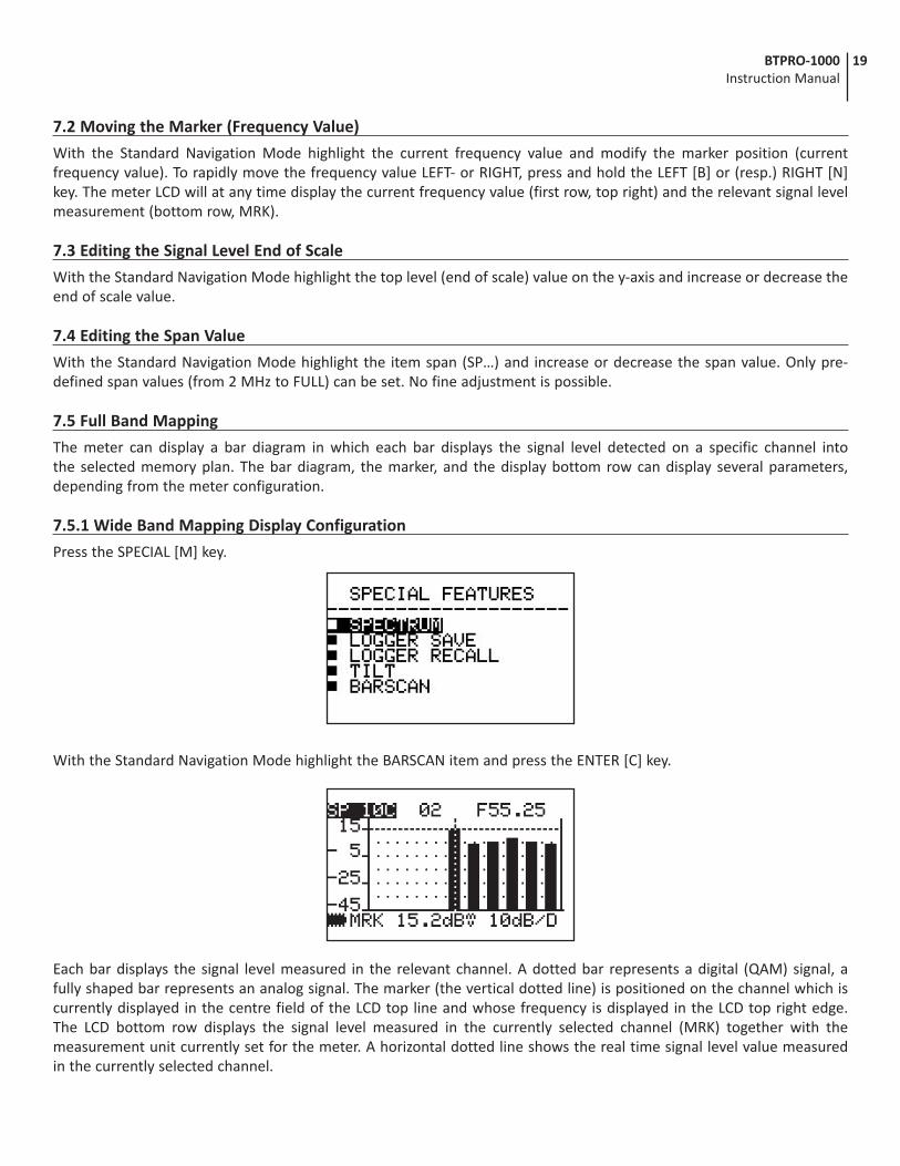
7.5.1 Wide Band Mapping Display Configuration
Press the SPECIAL [M] key.
With the Standard Navigation Mode highlight the BARSCAN item and press the ENTER [C] key.
Each bar displays the signal level measured in the relevant channel. A dotted bar represents a digital (QAM) signal, a fully shaped bar represents an analog signal. The marker (the vertical dotted line) is positioned on the channel which is currently displayed in the centre field of the LCD top line and whose frequency is displayed in the LCD top right edge. The LCD bottom row displays the signal level measured in the currently selected channel (MRK) together with the measurement unit currently set for the meter. A horizontal dotted line shows the real time signal level value measured in the currently selected channel.
20 BTPRO-1000 Instruction Manual
7.5.1a Surfing the Channels
With the Standard Navigation Mode highlight the channel number which is currently displayed in the centre field of the LCD top line, press the ENTER [C] key and move the marker on the desired channel.
7.5.1b Editing the End-of-Scale Value
With the Standard Navigation Mode highlight the top level (end of scale) value on the y-axis and select the desired end of scale value.
7.5.1c Editing the dB/DIV Value
With the Standard Navigation Mode highlight the dB/DIV value on the bottom right corner of the LCD, and set 5 dB/DIV or 10 dB/DIV.
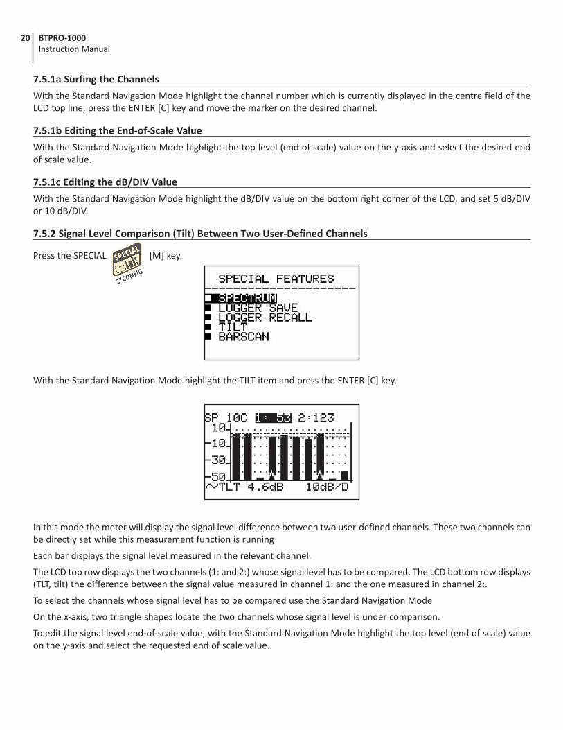
7.5.2 Signal Level Comparison (Tilt) Between Two User-Defined Channels
Press the SPECIAL [M] key.
With the Standard Navigation Mode highlight the TILT item and press the ENTER [C] key.
In this mode the meter will display the signal level difference between two user-defined channels. These two channels can be directly set while this measurement function is running
Each bar displays the signal level measured in the relevant channel.
The LCD top row displays the two channels (1: and 2:) whose signal level has to be compared. The LCD bottom row displays (TLT, tilt) the difference between the signal value measured in channel 1: and the one measured in channel 2:.
To select the channels whose signal level has to be compared use the Standard Navigation Mode
On the x-axis, two triangle shapes locate the two channels whose signal level is under comparison.
To edit the signal level end-of-scale value, with the Standard Navigation Mode highlight the top level (end of scale) value on the y-axis and select the requested end of scale value.
21BTPRO-1000 Instruction Manual
Section 8 – Cable System Measurements
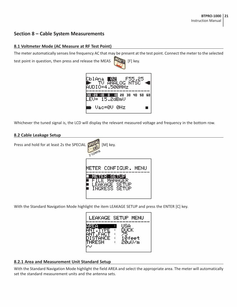
8.1 Voltmeter Mode (AC Measure at RF Test Point)
The meter automatically senses line frequency AC that may be present at the test point. Connect the meter to the selected
test point in question, then press and release the MEAS [F] key.
Whichever the tuned signal is, the LCD will display the relevant measured voltage and frequency in the bottom row.
8.2 Cable Leakage Setup
Press and hold for at least 2s the SPECIAL [M] key.
With the Standard Navigation Mode highlight the item LEAKAGE SETUP and press the ENTER [C] key.
8.2.1 Area and Measurement Unit Standard Setup
With the Standard Navigation Mode highlight the field AREA and select the appropriate area. The meter will automatically set the standard measurement units and the antenna sets.
22 BTPRO-1000 Instruction Manual
8.2.2 Antenna Type Setup
With the Standard Navigation highlight the field ANT.TYPE and select the appropriate antenna type.
8.2.3 Antenna Factor Setup
With the Standard Navigation highlight the field ANT.FACT. and select the appropriate antenna factor.
8.2.4 Distance Setup
With the Standard Navigation highlight the field DISTANCE and select the appropriate distance.
8.2.5 Threshold Setup
With the Standard Navigation highlight the field THRESH and select the appropriate threshold value in the measurement unit displayed on the LCD.
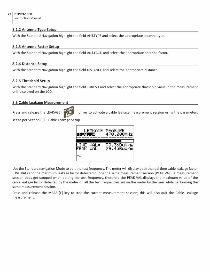
8.3 Cable Leakage Measurement
Press and release the LEAKAGE [L] key to activate a cable leakage measurement session using the parameters
set as per Section 8.2 - Cable Leakage Setup
Use the Standard navigation Mode to edit the test frequency. The meter will display both the real time cable leakage factor (LIVE VAL) and the maximum leakage factor detected during the same measurement session (PEAK VAL). A measurement session does get stopped when editing the test frequency, therefore the PEAK VAL displays the maximum value of the cable leakage factor detected by the meter on all the test frequencies set on the meter by the user while performing the same measurement session.
Press and release the MEAS [F] key to stop the current measurement session; this will also quit the Cable Leakage measurement.
23BTPRO-1000 Instruction Manual
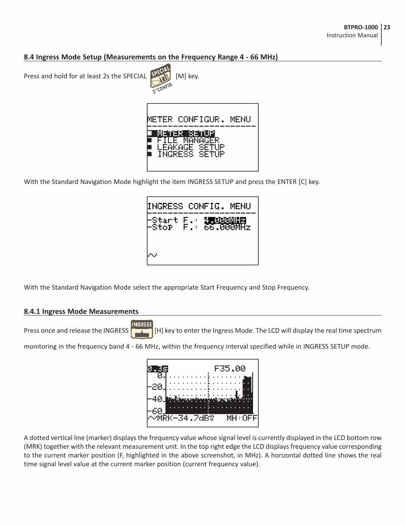
8.4 Ingress Mode Setup (Measurements on the Frequency Range 4 - 66 MHz)
Press and hold for at least 2s the SPECIAL [M] key.
With the Standard Navigation Mode highlight the item INGRESS SETUP and press the ENTER [C] key.
With the Standard Navigation Mode select the appropriate Start Frequency and Stop Frequency.
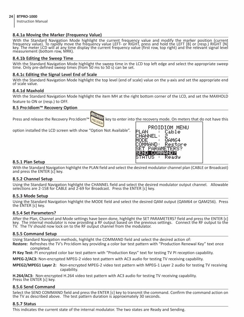
8.4.1 Ingress Mode Measurements
Press once and release the INGRESS [H] key to enter the Ingress Mode. The LCD will display the real time spectrum
monitoring in the frequency band 4 - 66 MHz, within the frequency interval specified while in INGRESS SETUP mode.
A dotted vertical line (marker) displays the frequency value whose signal level is currently displayed in the LCD bottom row (MRK) together with the relevant measurement unit. In the top right edge the LCD displays frequency value corresponding to the current marker position (F, highlighted in the above screenshot, in MHz). A horizontal dotted line shows the real time signal level value at the current marker position (current frequency value).
24 BTPRO-1000 Instruction Manual
8.4.1a Moving the Marker (Frequency Value)With the Standard Navigation Mode highlight the current frequency value and modify the marker position (current frequency value). To rapidly move the frequency value LEFT- or RIGHT, press and hold the LEFT [B] or (resp.) RIGHT [N] key. The meter LCD will at any time display the current frequency value (first row, top right) and the relevant signal level measurement (bottom row, MRK).
8.4.1b Editing the Sweep TimeWith the Standard Navigation Mode highlight the sweep time in the LCD top left edge and select the appropriate sweep time. Only pre-defined sweep times (from 50 ms to 50 s) can be set.
8.4.1c Editing the Signal Level End of ScaleWith the Standard Navigation Mode highlight the top level (end of scale) value on the y-axis and set the appropriate end of scale value.
8.4.1d MaxholdWith the Standard Navigation Mode highlight the item MH at the right bottom corner of the LCD, and set the MAXHOLD feature to ON or (resp.) to OFF.8.5 Pro:Idiom™ Recovery Option
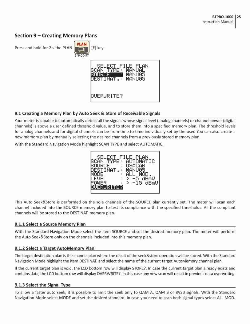
Press and release the Recovery Pro:Idiom™ key to enter into the recovery mode. On meters that do not have this
option installed the LCD screen with show “Option Not Available”.
8.5.1 Plan SetupWith the Standard Navigation highlight the PLAN field and select the desired modulator channel plan (CABLE or Broadcast) and press the ENTER [c] key.
8.5.2 Channel SetupUsing the Standard Navigation highlight the CHANNEL field and select the desired modulator output channel. Allowable selections are 2-158 for CABLE and 2-69 for Broadcast. Press the ENTER [c] key.
8.5.3 Mode SetupUsing the Standard Navigation highlight the MODE field and select the desired QAM output (QAM64 or QAM256). Press the ENTER [c] key.
8.5.4 Set Parameters?After the Plan, Channel and Mode settings have been done, highlight the SET PARAMETERS? field and press the ENTER [c] key. The internal modulator is now providing a RF output based on the previous settings. Connect the RF output to the TV. The TV should now lock on to the RF output channel from the modulator.
8.5.5 Command SetupUsing Standard Navigation methods, highlight the COMMAND field and select the desired action of:Restore: Refreshes the TV’s Pro:Idiom key providing a color bar test pattern with “Production Renewal Key” text once completed.PI Key Test: PI encrypted color bar test pattern with “Production Keys” text for testing TV PI reception capability. MPEG-2/AC3: Non-encrypted MPEG-2 video test pattern with AC3 audio for testing TV receiving capability.MPEG2/MPEG1 Layer 2: Non-encrypted MPEG-2 video test pattern with MPEG-1 Layer 2 audio for testing TV receiving capability. H.264/AC3: Non-encrypted H.264 video test pattern with AC3 audio for testing TV receiving capability.Press the ENTER [c] key.
8.5.6 Send CommandSelect the SEND COMMAND field and press the ENTER [c] key to transmit the command. Confirm the command action on the TV as described above. The test pattern duration is approximately 30 seconds.
8.5.7 StatusThis indicates the current state of the internal modulator. The two states are Ready and Sending.
25BTPRO-1000 Instruction Manual
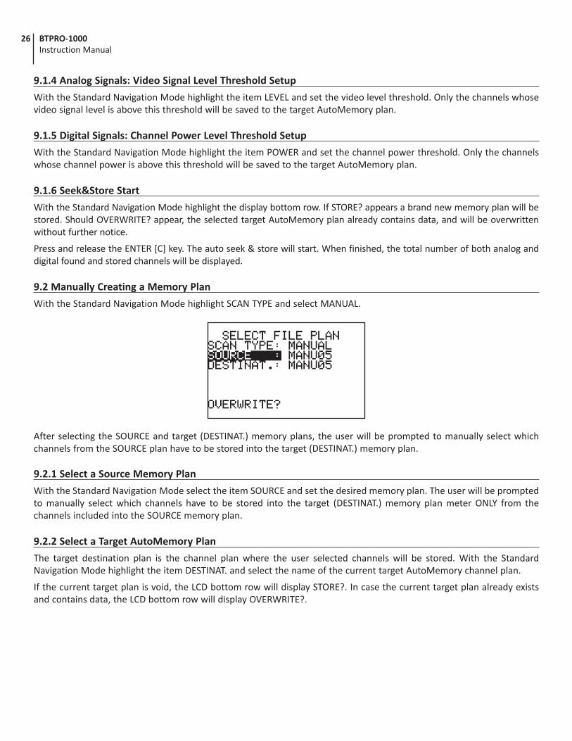
Section 9 – Creating Memory Plans
Press and hold for 2 s the PLAN [E] key.
9.1 Creating a Memory Plan by Auto Seek & Store of Receivable Signals
Your meter is capable to automatically detect all the signals whose signal level (analog channels) or channel power (digital channels) is above a user defined threshold value, and to store them into a specified memory plan. The threshold levels for analog channels and for digital channels can be from time to time individually set by the user. You can also create a new memory plan by manually selecting the desired channels from a previously stored memory plan.
With the Standard Navigation Mode highlight SCAN TYPE and select AUTOMATIC.
This Auto Seek&Store is performed on the sole channels of the SOURCE plan currently set. The meter will scan each channel included into the SOURCE memory plan to test its compliance with the specified thresholds. All the compliant channels will be stored to the DESTINAT. memory plan.
9.1.1 Select a Source Memory Plan
With the Standard Navigation Mode select the item SOURCE and set the desired memory plan. The meter will perform the Auto Seek&Store only on the channels included into this memory plan.
9.1.2 Select a Target AutoMemory Plan
The target destination plan is the channel plan where the result of the seek&store operation will be stored. With the Standard Navigation Mode highlight the item DESTINAT. and select the name of the current target AutoMemory channel plan.
If the current target plan is void, the LCD bottom row will display STORE?. In case the current target plan already exists and contains data, the LCD bottom row will display OVERWRITE?. In this case any new scan will result in previous data overwriting.
9.1.3 Select the Signal Type
To allow a faster auto seek, it is possible to limit the seek only to QAM A, QAM B or 8VSB signals. With the Standard Navigation Mode select MODE and set the desired standard. In case you need to scan both signal types select ALL MOD.
26 BTPRO-1000 Instruction Manual
9.1.4 Analog Signals: Video Signal Level Threshold Setup
With the Standard Navigation Mode highlight the item LEVEL and set the video level threshold. Only the channels whose video signal level is above this threshold will be saved to the target AutoMemory plan.
9.1.5 Digital Signals: Channel Power Level Threshold Setup
With the Standard Navigation Mode highlight the item POWER and set the channel power threshold. Only the channels whose channel power is above this threshold will be saved to the target AutoMemory plan.
9.1.6 Seek&Store Start
With the Standard Navigation Mode highlight the display bottom row. If STORE? appears a brand new memory plan will be stored. Should OVERWRITE? appear, the selected target AutoMemory plan already contains data, and will be overwritten without further notice.
Press and release the ENTER [C] key. The auto seek & store will start. When finished, the total number of both analog and digital found and stored channels will be displayed.
9.2 Manually Creating a Memory Plan
With the Standard Navigation Mode highlight SCAN TYPE and select MANUAL.
After selecting the SOURCE and target (DESTINAT.) memory plans, the user will be prompted to manually select which channels from the SOURCE plan have to be stored into the target (DESTINAT.) memory plan.
9.2.1 Select a Source Memory Plan
With the Standard Navigation Mode select the item SOURCE and set the desired memory plan. The user will be prompted to manually select which channels have to be stored into the target (DESTINAT.) memory plan meter ONLY from the channels included into the SOURCE memory plan.
9.2.2 Select a Target AutoMemory Plan
The target destination plan is the channel plan where the user selected channels will be stored. With the Standard Navigation Mode highlight the item DESTINAT. and select the name of the current target AutoMemory channel plan.
If the current target plan is void, the LCD bottom row will display STORE?. In case the current target plan already exists and contains data, the LCD bottom row will display OVERWRITE?.
27BTPRO-1000 Instruction Manual
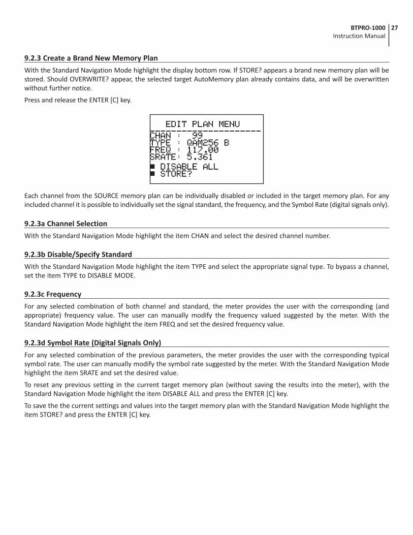
9.2.3 Create a Brand New Memory Plan
With the Standard Navigation Mode highlight the display bottom row. If STORE? appears a brand new memory plan will be stored. Should OVERWRITE? appear, the selected target AutoMemory plan already contains data, and will be overwritten without further notice.
Press and release the ENTER [C] key.
Each channel from the SOURCE memory plan can be individually disabled or included in the target memory plan. For any included channel it is possible to individually set the signal standard, the frequency, and the Symbol Rate (digital signals only).
9.2.3a Channel Selection
With the Standard Navigation Mode highlight the item CHAN and select the desired channel number.
9.2.3b Disable/Specify Standard
With the Standard Navigation Mode highlight the item TYPE and select the appropriate signal type. To bypass a channel, set the item TYPE to DISABLE MODE.
9.2.3c Frequency
For any selected combination of both channel and standard, the meter provides the user with the corresponding (and appropriate) frequency value. The user can manually modify the frequency valued suggested by the meter. With the Standard Navigation Mode highlight the item FREQ and set the desired frequency value.
9.2.3d Symbol Rate (Digital Signals Only)
For any selected combination of the previous parameters, the meter provides the user with the corresponding typical symbol rate. The user can manually modify the symbol rate suggested by the meter. With the Standard Navigation Mode highlight the item SRATE and set the desired value.
To reset any previous setting in the current target memory plan (without saving the results into the meter), with the Standard Navigation Mode highlight the item DISABLE ALL and press the ENTER [C] key.
To save the the current settings and values into the target memory plan with the Standard Navigation Mode highlight the item STORE? and press the ENTER [C] key.
28 BTPRO-1000 Instruction Manual
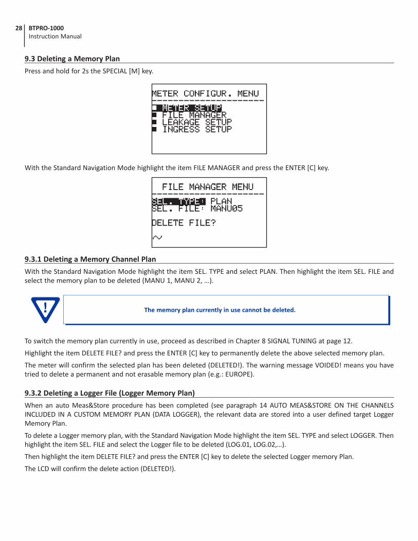
9.3 Deleting a Memory Plan
Press and hold for 2s the SPECIAL [M] key.
With the Standard Navigation Mode highlight the item FILE MANAGER and press the ENTER [C] key.
9.3.1 Deleting a Memory Channel Plan
With the Standard Navigation Mode highlight the item SEL. TYPE and select PLAN. Then highlight the item SEL. FILE and select the memory plan to be deleted (MANU 1, MANU 2, …).
To switch the memory plan currently in use, proceed as described in Chapter 8 SIGNAL TUNING at page 12.
Highlight the item DELETE FILE? and press the ENTER [C] key to permanently delete the above selected memory plan.
The meter will confirm the selected plan has been deleted (DELETED!). The warning message VOIDED! means you have tried to delete a permanent and not erasable memory plan (e.g.: EUROPE).
9.3.2 Deleting a Logger File (Logger Memory Plan)
When an auto Meas&Store procedure has been completed (see paragraph 14 AUTO MEAS&STORE ON THE CHANNELS INCLUDED IN A CUSTOM MEMORY PLAN (DATA LOGGER), the relevant data are stored into a user defined target Logger Memory Plan.
To delete a Logger memory plan, with the Standard Navigation Mode highlight the item SEL. TYPE and select LOGGER. Then highlight the item SEL. FILE and select the Logger file to be deleted (LOG.01, LOG.02,…).
Then highlight the item DELETE FILE? and press the ENTER [C] key to delete the selected Logger memory Plan.
The LCD will confirm the delete action (DELETED!).
The memory plan currently in use cannot be deleted.
29BTPRO-1000 Instruction Manual
Section 10 – Auto MEAS&STORE on the Channels Included in a Custom Memory Plan (Data Logger)
This meter can automatically tune all of the channels included in any memory plan (whichever the type) and therefore automatically perform all the available measurements on each of the tuned channels. The measurements results are stored into a user selected target file (LOGGER files).
Any LOGGER file can be downloaded to a PC in MS Excel® format using SMART® connection software.
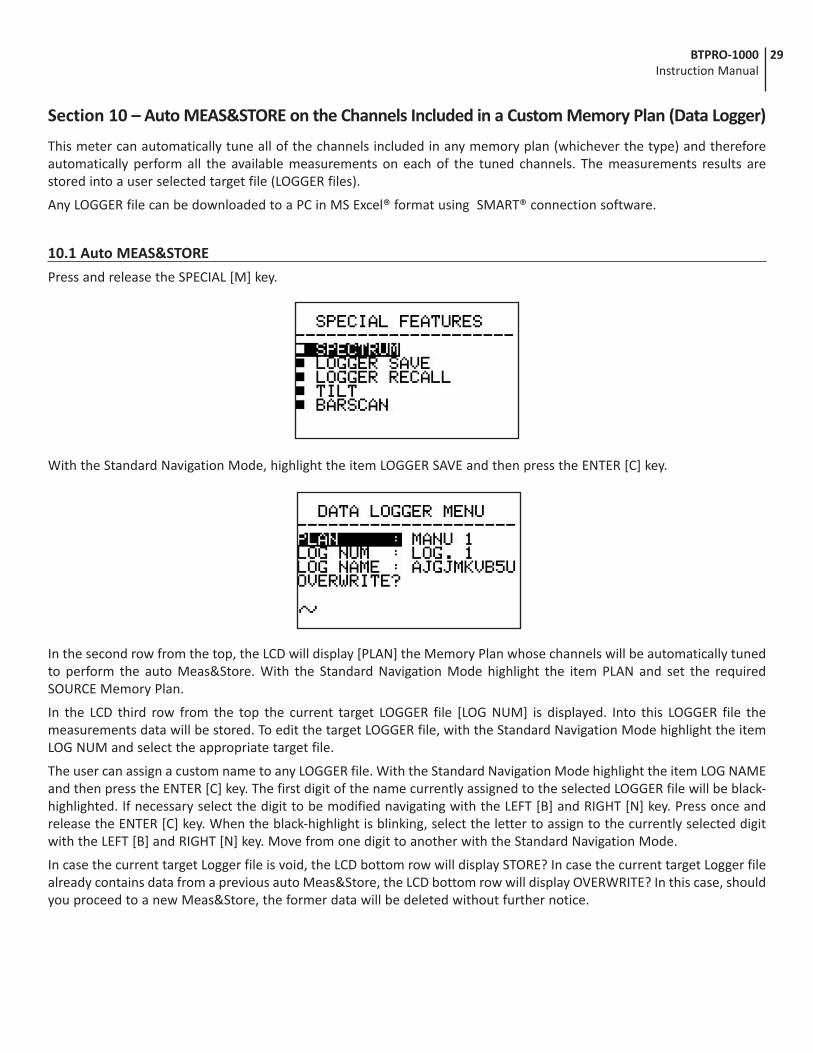
10.1 Auto MEAS&STORE
Press and release the SPECIAL [M] key.
With the Standard Navigation Mode, highlight the item LOGGER SAVE and then press the ENTER [C] key.
In the second row from the top, the LCD will display [PLAN] the Memory Plan whose channels will be automatically tuned to perform the auto Meas&Store. With the Standard Navigation Mode highlight the item PLAN and set the required SOURCE Memory Plan.
In the LCD third row from the top the current target LOGGER file [LOG NUM] is displayed. Into this LOGGER file the measurements data will be stored. To edit the target LOGGER file, with the Standard Navigation Mode highlight the item LOG NUM and select the appropriate target file.
The user can assign a custom name to any LOGGER file. With the Standard Navigation Mode highlight the item LOG NAME and then press the ENTER [C] key. The first digit of the name currently assigned to the selected LOGGER file will be black-highlighted. If necessary select the digit to be modified navigating with the LEFT [B] and RIGHT [N] key. Press once and release the ENTER [C] key. When the black-highlight is blinking, select the letter to assign to the currently selected digit with the LEFT [B] and RIGHT [N] key. Move from one digit to another with the Standard Navigation Mode.
In case the current target Logger file is void, the LCD bottom row will display STORE? In case the current target Logger file already contains data from a previous auto Meas&Store, the LCD bottom row will display OVERWRITE? In this case, should you proceed to a new Meas&Store, the former data will be deleted without further notice.
30 BTPRO-1000 Instruction Manual
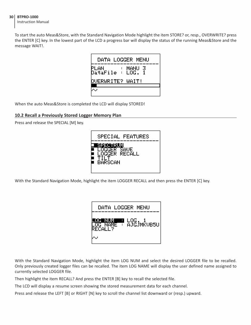
To start the auto Meas&Store, with the Standard Navigation Mode highlight the item STORE? or, resp., OVERWRITE? press the ENTER [C] key. In the lowest part of the LCD a progress bar will display the status of the running Meas&Store and the message WAIT!.
When the auto Meas&Store is completed the LCD will display STORED!
10.2 Recall a Previously Stored Logger Memory Plan
Press and release the SPECIAL [M] key.
With the Standard Navigation Mode, highlight the item LOGGER RECALL and then press the ENTER [C] key.
With the Standard Navigation Mode, highlight the item LOG NUM and select the desired LOGGER file to be recalled. Only previously created logger files can be recalled. The item LOG NAME will display the user defined name assigned to currently selected LOGGER file.
Then highlight the item RECALL? And press the ENTER [B] key to recall the selected file.
The LCD will display a resume screen showing the stored measurement data for each channel.
Press and release the LEFT [B] or RIGHT [N] key to scroll the channel list downward or (resp.) upward.

31BTPRO-1000 Instruction Manual
Section 11 – Maintaining the Meter
11.1 Cleaning the Meter
Cleaning the meter from dust and dirt is easy and helps to maintain it in optimal working conditions. The cleaning procedure is simple and quick and requires only minor attention.
Never use chemical aggressive products (diluent) and/or abrasive or rough clothes which may damage plastics and displays.
Always use a soft cloth, damped with a simple water and alcohol solution or a de-greasing not abrasive liquid soap.
Keyboard and display should be gently cleaned. Rubbing the keyboard and/or the display(s) may seriously damage their functions.
11.2 Maintenance and Care of the Meter
This meter has been designed to withstand severe conditions of use. Even so, its life may be prolonged by respecting some simple and effective rules:
• The meter has not been designed to withstand high temperatures (over 60°C or 140°F). Those temperatures can be easily reached when the meter is left in a car, especially behind the windshield, or in the trunk. The LCD display and/or other details may easily be damaged by the extreme temperature.
• The internal battery may rapidly loose its efficiency if exposed to high or low temperatures. This will result in reduced autonomy of the meter when powered by internal battery.
• When recharging the internal battery, allow good air circulation around the meter and the adapter.
• The meter is not waterproof, even if it is protected against incidental water drops. In case of contact with water, when electronic circuits may be damaged, allow the meter to dry thoroughly before trying to turn it on. Do not use a hairdryer or other strong heating sources.
• The graphic display is protected by a special glass screen. If hit, this protective screen may adhere to the actual display, causing a stain effect. The result will be a reduced visibility and blind spots on the screen. It is possible to solve this inconvenience by applying a strip of mild paper-masking tape to the display and gently pulling it out. Do not use any kind of strong adhesive tape (electrical tape, duct tape or even scotch tape) which may leave glue stains on the display. In case of doubt, please contact the Blonder Tongue Technical Solutions Department.
Limited WarrantyBlonder Tongue Laboratories, Inc. (BT) will at its sole option, either repair or replace (with a new or factory reconditioned product, as BT may determine) any product manufactured by BT which proves to be defective in materials or workmanship or fails to meet the specifications which are in effect on the date of shipment or such other specifications as may have been expressly agreed upon in writing (i) for a period of one (1) year from the date of original purchase (or such shorter period of time as may be set forth in the license agreement specific to the particular software being licensed), with respect to iCentral™ (hardware and software) and all other software products (including embedded software) licensed from BT, (ii)) for a period of one (1) year from the date of original purchase, with respect to all MegaPort, IPTV products and fiber optics receivers, transmitters, couplers and integrated receivers/distribution amplifiers (including TRAILBLAZER™, RETRO-LINX™ and TWIN STAR™ products) as well as for VideoCipher® & DigiCipher® satellite receivers, and (iii) for a period of three (3) years from the date of original purchase, with respect to all other BT products. Notwithstanding the foregoing, in some cases, the warranty on certain proprietary sub-assembly modules manufactured by third party vendors and contained in BT products and on certain private-label products manufactured by third parties for resale by BT are of shorter duration or otherwise more limited than the standard BT limited warranty. In such cases, BT’s warranty with respect to such third party proprietary sub-assembly modules and private-label products will be limited to the duration and other terms of such third party vendor’s warranty. In addition, certain products, that are not manufactured but are resold by BT, carry the original OEM warranty for that product. The limited warranty set forth in this paragraph does not apply to any product sold by BT, which at the time of sale constituted a Closeout Product.
BT will at its sole option, either repair or replace (with a new or factory reconditioned product, as BT may determine) any product sold by BT which at the time of sale constituted a refurbished or closeout items (“Refurbished Product” and “Closeout Product”), which proves to be defective in materials or workmanship or fails to meet the specifications which are in effect on the date of shipment or such other specifications as may have been expressly agreed upon in writing, for a period of ninety (90) days from the date of original purchase. Notwithstanding the foregoing, in some cases, the warranty on third party software and on certain proprietary sub-assembly modules manufactured by third party vendors and contained in BT products and on certain private-label products manufactured by third parties for resale by BT are of shorter duration or otherwise more limited than the BT limited warranty for Closeout Products. In such cases, BT’s warranty for Closeout Products constituting such third party software, third party proprietary sub-assembly modules and private-label products will be limited to the duration and other terms of such third party vendor’s warranty. In addition, notwithstanding the foregoing, (i) certain Closeout Products that are not manufactured (but are resold) by BT, carry the original OEM warranty for such products, which may be longer or shorter than the BT limited warranty for Refurbished or Closeout Products. All sales of Refurbished or Closeout Products are final.
To obtain service under this warranty, the defective product, together with a copy of the sales receipt or other satisfactory proof of purchase and a brief description of the defect, must be shipped freight prepaid to: Blonder Tongue Laboratories, Inc., One Jake Brown Road, Old Bridge, New Jersey 08857.
This warranty does not cover damage resulting from (i) use or installation other than in strict accordance with manufacturer’s written instructions, (ii) disassembly or repair by someone other than the manufacturer or a manufacturer-authorized repair center, (iii) misuse, misapplication or abuse, (iv) alteration, (v) lack of reasonable care or (vi) wind, ice, snow, rain, lightning, or any other weather conditions or acts of God.
OTHER THAN THE WARRANTIES SET FORTH ABOVE, BT MAKES NO OTHER WARRANTIES OR REPRESENTA-TIONS OF ANY KIND, EXPRESS OR IMPLIED, AS TO THE CONDITION, DESCRIPTION, FITNESS FOR A PARTIC-ULAR PURPOSE, MERCHANTABILITY OR AS TO ANY OTHER MATTER, AND SUCH WARRANTIES SUPERSEDE ANY ORAL OR WRITTEN WARRANTIES OR REPRESENTATIONS MADE OR IMPLIED BY BT OR BY ANY OF BT’S EMPLOYEES OR REPRESENTATIVES, OR IN ANY OF BT’S BROCHURES, MANUALS, CATALOGS, LITERATURE OR OTHER MATERIALS. IN ALL CASES, BUYER’S SOLE AND EXCLUSIVE REMEDY AND BT’S SOLE OBLIGA-TION FOR ANY BREACH OF THE WARRANTIES CONTAINED HEREIN SHALL BE LIMITED TO THE REPAIR OR REPLACEMENT OF THE DEFECTIVE PRODUCT F.O.B. SHIPPING POINT, AS BT IN ITS SOLE DISCRETION SHALL DETERMINE. BT SHALL IN NO EVENT AND UNDER NO CIRCUMSTANCES BE LIABLE OR RESPONSIBLE FOR ANY CONSEQUENTIAL, INDIRECT, INCIDENTAL, PUNITIVE, DIRECT OR SPECIAL DAMAGES BASED UPON BREACH OF WARRANTY, BREACH OF CONTRACT, NEGLIGENCE, STRICT TORT LIABILITY OR OTHERWISE OR ANY OTHER LEGAL THEORY ARISING DIRECTLY OR INDIRECTLY FROM THE SALE, USE, INSTALLATION OR FAILURE OF ANY PRODUCT ACQUIRED BY BUYER FROM BT.
All claims for shortages, defects and non-conforming goods must be made by Buyer in writing within five (5) days of receipt of merchandise, which writing shall state with particularity all material facts, concerning the claim then known to Buyer. Upon any such complaint, Buyer shall hold the goods complained of intact and duly protected, for a period of up to sixty (60) days. Upon the request of BT, Buyer shall ship such allegedly nonconforming or defective goods, freight prepaid to BT for examination by BT’s inspection department and verification of the defect. BT, at its option, will either repair, replace or issue a credit for products determined to be defective. BT’s liability and responsibility for defective products is specifically limited to the defective item or to credit towards the original billing. All such replacements by BT shall be made free of charge f.o.b. the delivery point called for in the original order. Products for which replacement has been made under the provisions of this clause shall become the property of BT. Under no circumstances are products to be returned to BT without BT’s prior written authorization. BT reserves the right to scrap any unauthorized returns on a no-credit basis. Any actions for breach of this contract must be commenced by Buyer within thirteen (13) months after the cause of action has accrued. A copy of BT’s standard terms and conditions of sale, including the limited warranty, is available from BT upon request. Copies of the limited warranties covering third party proprietary sub-assembly modules and private label products manufactured by third parties are also available from BT on request. VideoCipher® & DigiCipher® are registered trademarks of Motorola Corp.
Rev 5/6/2009
Blonder Tongue Laboratories, Inc.
Limited Warranty
Blonder Tongue Laboratories, Inc. (BT) will at its sole option, either repair or replace (with a new or factory reconditioned product, as BT may determine) any product manufactured by BT which proves to be defective in materials or workmanship or fails to meet the specifications which are in effect on the date of shipment or such other specifications as may have been expressly agreed upon in writing (i) for a period of one (1) year from the date of original purchase (or such shorter period of time as may be set forth in the license agreement specific to the particular software being licensed), with respect to iCentral™ (hardware and software) and all other software products (including embedded software) licensed from BT, (ii) ) for a period of one (1) year from the date of original purchase, with respect to all MegaPort™, IPTV products, and fiber optics receivers, transmitters, couplers and integrated receiver/distribution amplifiers (including TRAILBLAZER™, RETRO-LINX™ and TWIN STAR™ products) as well as for DigiCipher ® satellite receivers, and (iii) for a period of three (3) years from the date of original purchase, with respect to all other BT products. Notwithstanding the foregoing, in some cases, the warranty on certain proprietary sub-assembly modules manufactured by third-party vendors and contained in BT products and on certain private–label products manufactured by third-parties for resale by BT are of shorter duration or otherwise more limited than the standard BT limited warranty. In such cases, BT's warranty with respect to such third-party proprietary sub-assembly modules and private-label products will be limited to the duration and other terms of such third-party vendor's warranty. In addition, certain products, that are not manufactured but are resold by BT, carry the original OEM warranty for such products. The limited warranty set forth in this paragraph does not apply to any product sold by BT, which at the time of sale constituted a Refurbished/Closeout Product.
(b) BT will at its sole option, either repair or replace (with a new or factory-reconditioned product, as BT may determine) any product sold by BT which at the time of sale constituted a refurbished or closeout item (“Refurbished/Closeout Product”), which proves to be defective in materials or workmanship or fails to meet the specifications which are in effect on the date of shipment or such other specifications as may have been expressly agreed upon in writing, for a period of ninety (90) days from the date of original purchase. Notwithstanding the foregoing, in some cases the warranty on third party software and on certain proprietary sub-assembly modules manufactured by third-party vendors and contained in BT products and on certain private–label products manufactured by third-parties for resale by BT are of shorter duration or otherwise more limited than the BT limited warranty for Refurbished/Closeout Products. In such cases, BT's warranty for Refurbished/Closeout Products constituting such third party software, third-party proprietary sub-assembly modules and private-label products will be limited to the duration and other terms of such third-party vendor's warranty. In addition, notwithstanding the foregoing, (i) certain Refurbished/Closeout Products that are not manufactured (but are resold) by BT, carry the original OEM warranty for such products, which may be longer or shorter than the BT limited warranty for Refurbished/Closeout Products. All sales of Refurbished/Closeout Products are final.
To obtain service under this warranty, the defective product, together with a copy of the sales receipt or other satisfactory proof of purchase and a brief description of the defect, must be shipped freight prepaid to: Blonder Tongue Laboratories, Inc., One Jake Brown Road, Old Bridge, New Jersey 08857.
This warranty does not cover damage resulting from (i) use or installation other than in strict accordance with manufacturer's written instructions, (ii) disassembly or repair by someone other than the manufacturer or a manufacturer-authorized repair center, (iii) misuse, misapplication or abuse, (iv) alteration, (v) lack of reasonable care or (vi) wind, ice, snow, rain, lightning, or any other weather conditions or acts of God.
OTHER THAN THE WARRANTIES SET FORTH ABOVE, BT MAKES NO OTHER WARRANTIES OR REPRESENTATIONS OF ANY KIND, EXPRESS OR IMPLIED, AS TO THE CONDITION, DESCRIPTION, FITNESS FOR A PARTICULAR PURPOSE, MERCHANTABILITY, OR AS TO ANY OTHER MATTER, AND SUCH WARRANTIES SUPERSEDE ANY ORAL OR WRITTEN WARRANTIES OR REPRESENTATIONS MADE OR IMPLIED BY BT OR BY ANY OF BT’S EMPLOYEES OR REPRESENTATIVES, OR IN ANY OF BT’S BROCHURES MANUALS, CATALOGS, LITERATURE OR OTHER MATERIALS. IN ALL CASES, BUYER’S SOLE AND EXCLUSIVE REMEDY AND BT’S SOLE OBLIGATION FOR ANY BREACH OF THE WARRANTIES CONTAINED HEREIN SHALL BE LIMITED TO THE REPAIR OR REPLACEMENT OF THE DEFECTIVE PRODUCT F.O.B. SHIPPING POINT, AS BT IN ITS SOLE DISCRETION SHALL DETERMINE. BT SHALL IN NO EVENT AND UNDER NO CIRCUMSTANCES BE LIABLE OR RESPONSIBLE FOR ANY CONSEQUENTIAL, INDIRECT, INCIDENTAL, PUNITIVE, DIRECT OR SPECIAL DAMAGES BASED UPON BREACH OF WARRANTY, BREACH OF CONTRACT, NEGLIGENCE, STRICT TORT LIABILITY OR OTHERWISE OR ANY OTHER LEGAL THEORY, ARISING DIRECTLY OR INDIRECTLY FROM THE SALE, USE, INSTALLATION OR FAILURE OF ANY PRODUCT ACQUIRED BY BUYER FROM BT.
All claims for shortages, defects, and non-conforming goods must be made by the customer in writing within five (5) days of receipt of merchandise, which writing shall state with particularity all material facts concerning the claim then known to the customer. Upon any such claim, the customer shall hold the goods complained of intact and duly protected, for a period of up to sixty (60) days. Upon the request of BT, the customer shall ship such allegedly non-conforming or defective goods, freight prepaid to BT for examination by BT's inspection department and verification of the defect. BT, at its option, will either repair, replace or issue a credit for products determined to be defective. BT's liability and responsibility for defective products is specifically limited to the defective item or to credit towards the original billing. All such replacements by BT shall be made free of charge f.o.b. the delivery point called for in the original order. Products for which replacement has been made under the provisions of this clause shall become the property of BT. Under no circumstances are products to be returned to BT without BT's prior written authorization. BT reserves the right to scrap any unauthorized returns on a no-credit basis. Any actions for breach of a contract of sale between BT and a customer must be commenced by the customer within thirteen (13) months after the cause of action has accrued. A copy of BT's standard terms and conditions of sale, including the limited warranty, is available from BT upon request. Copies of the limited warranties covering third-party proprietary sub-assembly modules and private-label products manufactured by third-parties are also available from BT on request. DigiCipher ® is a registered trademark of Motorola Corp. (Rev 0509)
Seller will at its sole option, either repair or replace (with a new or factory reconditioned product, as Seller may determine) any product manufactured or sold (or in the case of software, licensed) by Seller which is defective in materials or workmanship or fails to meet the applicable specifications that are in effect on the date of shipment or such other specifications as may have been expressly agreed upon in writing: (i) for a period of three (3) years from the date of original purchase for all stock hardware products (other than those specifically referenced herein below having a shorter warranty period); (ii) for a period of one (1) year from the date of original purchase, with respect to all MegaPort™, IPTV products, test equipment and fiber optics receivers, transmitters, couplers and integrated receiver/distribution amplifiers; (iii) for a period of one (1) year from the date of original purchase (or such shorter period of time as may be set forth in the license agreement specific to the particular software being licensed from Seller) with respect to all software products licensed from Seller (other than Core Product Software) that is (a) developed for a specific function or application, (b) complimentary to and does not function without the Core Product Software, and (c) listed with a specific model number and stock number in Seller’s Price List (“Non-Core Software”); (iv) for a period of ninety (90) days from the date of original purchase, with respect to non-serialized products and accessories, such as parts, sub-assemblies, splitters and all other products sold by Seller (other than Core Product Software and Refurbished/Closeout Products) not otherwise referred to in clauses (i) through (iii) above. The warranty period for computer programs in machine-readable form included in a hardware product, which are essential for the functionality thereof as specifically stated in the published product specifications (“Core Product Software”) will be coincident with the warranty period of the applicable hardware product within which such Core Product Software is installed.
Software patches, bug fixes, updates or workarounds do not extend the original warranty period of any Core Product Software or Non-Core Software.
Notwithstanding anything herein to the contrary,
(i) Seller’s sole obligation for software that when properly installed and used does not substantially conform to the published specifications in effect when the software is first shipped by Seller, is to use commercially reasonable efforts to correct any reproducible material non-conformity (as determined by Seller in its sole discretion) by providing the customer with: (a) telephone or e-mail access to report non-conformance so that Seller can verify reproducibility, (b) a software patch or bug fix, if available or a workaround to bypass the issue if available, and (c) where applicable, replacement or damaged or defective external media, such as CD-ROM disk, on which the software was originally delivered;
(ii) Seller does not warrant that the use of any software will be uninterrupted, error-free, free of security vulnerabilities or that the software will meet the customer’s particular requirements; and the customer’s sole and exclusive remedy for breach of this warranty is, at Seller’s option, to receive (a) suitably modified software, or part thereof, or (b) comparable replacement software or part thereof;
(iii) Seller retains all right, title and interest in and to and ownership of all software (including all Core Product Software and Non-Core Software) including any and all enhancements, modifications and updates to the same; and
(iv) in some cases, the warranty on certain proprietary sub-assembly modules manufactured by third-party vendors and contained in Seller’s products, third party software installed in certain of Seller’s products, and on certain private–label products manufactured by third-parties for resale by Seller, will be of shorter duration or otherwise more limited than the standard Seller limited warranty. In such cases, Seller's warranty with respect to such third-party proprietary sub-assembly modules, third-party software and private-label products will be limited to the duration and other terms of such third-party vendor's warranty, if any. In addition, certain products, that are not manufactured by Seller, but are resold by Seller, may carry the original OEM warranty for such products, if any. The limited warranty set forth above does not apply to any product sold by Seller, which at the time of sale constituted a Refurbished/Closeout Product, the limited warranty for which is provided in the following paragraph.
Seller will at its sole option, either repair or replace (with a new or factory-reconditioned product, as Seller may determine) any product sold by Seller which at the time of sale constituted a refurbished or closeout item (“Refurbished/Closeout Product”), which is defective in materials or workmanship or fails to meet the applicable specifications that are in effect on the date of shipment of that product or fails to meet such other specifications as may have been expressly agreed upon in writing between the parties, for a period of ninety (90) days from the date of original purchase. Notwithstanding the foregoing, in some cases the warranty on certain proprietary sub-assembly modules manufactured by third-party vendors and contained in Seller products, third party software installed in certain of Seller’s products, and on certain private–label products manufactured by third-parties for resale by Seller will be of shorter duration or otherwise more limited than Seller limited warranty for Refurbished/Closeout Products. In such cases, Seller's warranty for Refurbished/Closeout Products constituting such third party proprietary sub-assembly modules, third party software, and private-label products will be limited to the duration and other terms of such third-party vendor's warranty, if any. In addition, notwithstanding the foregoing, (i) certain Refurbished/Closeout Products that are not manufactured (but are resold) by Seller, may carry the original OEM warranty for such products, if any, which may be longer or shorter than Seller’s limited warranty for Refurbished/Closeout Products. All sales of Refurbished/Closeout Products are final.
To obtain service under this warranty, the defective product, together with a copy of the sales receipt, serial number if applicable, or other satisfactory proof of purchase and a brief description of the defect, must be shipped freight prepaid to Seller at the following address: One Jake Brown Road, Old Bridge, New Jersey 08857.
This warranty does not cover failure of performance or damage resulting from (i) use or installation other than in strict accordance with manufacturer's written instructions, (ii) disassembly or repair by someone other than the manufacturer or a manufacturer-authorized repair center, (iii) misuse, misapplication or abuse, (iv) alteration, (v) exposure to unusual physical or electrical stress, abuse or accident or forces or exposure beyond normal use within specified operational or environmental parameters set forth in applicable product specifications, (vi) lack of reasonable care or (vii) wind, ice, snow, rain, lightning, or any other weather conditions or acts of God.
OTHER THAN THE WARRANTIES SET FORTH ABOVE, SELLER MAKES NO OTHER WARRANTIES OR REPRESENTATIONS OF ANY KIND, EXPRESS OR IMPLIED, AS TO THE CONDITION, DESCRIPTION, FITNESS FOR A PARTICULAR PURPOSE, MERCHANTABILITY, OR AS TO ANY OTHER MATTER, AND SUCH WARRANTIES SET FORTH ABOVE SUPERSEDE ANY ORAL OR WRITTEN WARRANTIES OR REPRESENTATIONS MADE OR IMPLIED BY SELLER OR BY ANY OF SELLER’S EMPLOYEES OR REPRESENTATIVES, OR IN ANY OF SELLER’S BROCHURES MANUALS, CATALOGS, LITERATURE OR OTHER MATERIALS. IN ALL CASES, BUYER’S SOLE AND EXCLUSIVE REMEDY AND SELLER’S SOLE OBLIGATION FOR ANY BREACH OF THE WARRANTIES CONTAINED HEREIN SHALL BE LIMITED TO THE REPAIR OR REPLACEMENT OF THE DEFECTIVE PRODUCT F.O.B. SHIPPING POINT, AS SELLER IN ITS SOLE DISCRETION SHALL DETERMINE. SELLER SHALL IN NO EVENT AND UNDER NO CIRCUMSTANCES BE LIABLE OR RESPONSIBLE FOR ANY CONSEQUENTIAL, INDIRECT, INCIDENTAL, PUNITIVE, DIRECT OR SPECIAL DAMAGES BASED UPON BREACH OF WARRANTY, BREACH OF CONTRACT, NEGLIGENCE, STRICT TORT LIABILITY OR OTHERWISE OR ANY OTHER LEGAL THEORY, ARISING DIRECTLY OR INDIRECTLY FROM THE SALE, USE, INSTALLATION OR FAILURE OF ANY PRODUCT ACQUIRED BY BUYER FROM SELLER.
All claims for shortages, defects, and non-conforming goods must be made by the customer in writing within five (5) days of receipt of merchandise, which writing shall state with particularity all material facts concerning the claim then known to the customer. Upon any such claim, the customer shall hold the goods complained of intact and duly protected, for a period of up to sixty (60) days. Upon the request of Seller, the customer shall ship such allegedly non-conforming or defective goods, freight prepaid to Seller for examination by Seller's inspection department and verification of the defect. Seller, at its option, will either repair, replace or issue a credit for products determined to be defective. Seller's liability and responsibility for defective products is specifically limited to the defective item or to credit towards the original billing. All such replacements by Seller shall be made free of charge f.o.b. the delivery point called for in the original order. Products for which replacement has been made under the provisions of this clause shall become the property of Seller. Under no circumstances are products to be returned to Seller without Seller's prior written authorization. Seller reserves the right to scrap any unauthorized returns on a no-credit basis. Any actions for breach of a contract of sale between Seller and a customer must be commenced by the customer within thirteen (13) months after the cause of action has accrued. A copy of Seller's standard terms and conditions of sale, including the limited warranty, is available from Seller upon request. Copies of the l imited warranties covering third-party proprietary sub-assembly modules and private-label products manufactured by third-parties may also be available from Seller on request. (Rev 0713)
One Jake Brown Road Old Bridge, NJ 08857-1000 USA
(800) 523-6049 • (732) 679-4000 • FAX: (732) 679-4353 www.blondertongue.com
Limited WarrantyBlonder Tongue Laboratories, Inc. (BT) will at its sole option, either repair or replace (with a new or factory reconditioned product, as BT may determine) any product manufactured by BT which proves to be defective in materials or workmanship or fails to meet the specifications which are in effect on the date of shipment or such other specifications as may have been expressly agreed upon in writing (i) for a period of one (1) year from the date of original purchase (or such shorter period of time as may be set forth in the license agreement specific to the particular software being licensed), with respect to iCentral™ (hardware and software) and all other software products (including embedded software) licensed from BT, (ii)) for a period of one (1) year from the date of original purchase, with respect to all MegaPort, IPTV products and fiber optics receivers, transmitters, couplers and integrated receivers/distribution amplifiers (including TRAILBLAZER™, RETRO-LINX™ and TWIN STAR™ products) as well as for VideoCipher® & DigiCipher® satellite receivers, and (iii) for a period of three (3) years from the date of original purchase, with respect to all other BT products. Notwithstanding the foregoing, in some cases, the warranty on certain proprietary sub-assembly modules manufactured by third party vendors and contained in BT products and on certain private-label products manufactured by third parties for resale by BT are of shorter duration or otherwise more limited than the standard BT limited warranty. In such cases, BT’s warranty with respect to such third party proprietary sub-assembly modules and private-label products will be limited to the duration and other terms of such third party vendor’s warranty. In addition, certain products, that are not manufactured but are resold by BT, carry the original OEM warranty for that product. The limited warranty set forth in this paragraph does not apply to any product sold by BT, which at the time of sale constituted a Closeout Product.
BT will at its sole option, either repair or replace (with a new or factory reconditioned product, as BT may determine) any product sold by BT which at the time of sale constituted a refurbished or closeout items (“Refurbished Product” and “Closeout Product”), which proves to be defective in materials or workmanship or fails to meet the specifications which are in effect on the date of shipment or such other specifications as may have been expressly agreed upon in writing, for a period of ninety (90) days from the date of original purchase. Notwithstanding the foregoing, in some cases, the warranty on third party software and on certain proprietary sub-assembly modules manufactured by third party vendors and contained in BT products and on certain private-label products manufactured by third parties for resale by BT are of shorter duration or otherwise more limited than the BT limited warranty for Closeout Products. In such cases, BT’s warranty for Closeout Products constituting such third party software, third party proprietary sub-assembly modules and private-label products will be limited to the duration and other terms of such third party vendor’s warranty. In addition, notwithstanding the foregoing, (i) certain Closeout Products that are not manufactured (but are resold) by BT, carry the original OEM warranty for such products, which may be longer or shorter than the BT limited warranty for Refurbished or Closeout Products. All sales of Refurbished or Closeout Products are final.
To obtain service under this warranty, the defective product, together with a copy of the sales receipt or other satisfactory proof of purchase and a brief description of the defect, must be shipped freight prepaid to: Blonder Tongue Laboratories, Inc., One Jake Brown Road, Old Bridge, New Jersey 08857.
This warranty does not cover damage resulting from (i) use or installation other than in strict accordance with manufacturer’s written instructions, (ii) disassembly or repair by someone other than the manufacturer or a manufacturer-authorized repair center, (iii) misuse, misapplication or abuse, (iv) alteration, (v) lack of reasonable care or (vi) wind, ice, snow, rain, lightning, or any other weather conditions or acts of God.
OTHER THAN THE WARRANTIES SET FORTH ABOVE, BT MAKES NO OTHER WARRANTIES OR REPRESENTATIONS OF ANY KIND, EXPRESS OR IMPLIED, AS TO THE CONDITION, DESCRIPTION, FITNESS FOR A PARTICULAR PURPOSE, MER-CHANTABILITY OR AS TO ANY OTHER MATTER, AND SUCH WARRANTIES SUPERSEDE ANY ORAL OR WRITTEN WAR-RANTIES OR REPRESENTATIONS MADE OR IMPLIED BY BT OR BY ANY OF BT’S EMPLOYEES OR REPRESENTATIVES, OR IN ANY OF BT’S BROCHURES, MANUALS, CATALOGS, LITERATURE OR OTHER MATERIALS. IN ALL CASES, BUYER’S SOLE AND EXCLUSIVE REMEDY AND BT’S SOLE OBLIGATION FOR ANY BREACH OF THE WARRANTIES CONTAINED HEREIN SHALL BE LIMITED TO THE REPAIR OR REPLACEMENT OF THE DEFECTIVE PRODUCT F.O.B. SHIPPING POINT, AS BT IN ITS SOLE DISCRETION SHALL DETERMINE. BT SHALL IN NO EVENT AND UNDER NO CIRCUMSTANCES BE LIABLE OR RESPONSIBLE FOR ANY CONSEQUENTIAL, INDIRECT, INCIDENTAL, PUNITIVE, DIRECT OR SPECIAL DAMAGES BASED UPON BREACH OF WARRANTY, BREACH OF CONTRACT, NEGLIGENCE, STRICT TORT LIABILITY OR OTHERWISE OR ANY OTHER LEGAL THEORY ARISING DIRECTLY OR INDIRECTLY FROM THE SALE, USE, INSTALLATION OR FAILURE OF ANY PRODUCT ACQUIRED BY BUYER FROM BT.
All claims for shortages, defects and non-conforming goods must be made by Buyer in writing within five (5) days of receipt of merchandise, which writing shall state with particularity all material facts, concerning the claim then known to Buyer. Upon any such complaint, Buyer shall hold the goods complained of intact and duly protected, for a period of up to sixty (60) days. Upon the request of BT, Buyer shall ship such allegedly nonconforming or defective goods, freight prepaid to BT for examination by BT’s inspection department and verification of the defect. BT, at its option, will either repair, replace or issue a credit for products determined to be defective. BT’s liability and responsibility for defective products is specifically limited to the defective item or to credit towards the original billing. All such replacements by BT shall be made free of charge f.o.b. the delivery point called for in the original order. Products for which replacement has been made under the provisions of this clause shall become the property of BT. Under no circumstances are products to be returned to BT without BT’s prior written authorization. BT reserves the right to scrap any unauthorized returns on a no-credit basis. Any actions for breach of this contract must be commenced by Buyer within thirteen (13) months after the cause of action has accrued. A copy of BT’s standard terms and conditions of sale, including the limited warranty, is available from BT upon request. Copies of the limited warranties covering third party proprietary sub-assembly modules and private label products manufactured by third parties are also available from BT on request. VideoCipher® & DigiCipher® are registered trademarks of Motorola Corp.
Rev 5/6/2009
Blonder Tongue Laboratories, Inc.
Limited Warranty
Blonder Tongue Laboratories, Inc. (BT) will at its sole option, either repair or replace (with a new or factory reconditioned product, as BT may determine) any product manufactured by BT which proves to be defective in materials or workmanship or fails to meet the specifications which are in effect on the date of shipment or such other specifications as may have been expressly agreed upon in writing (i) for a period of one (1) year from the date of original purchase (or such shorter period of time as may be set forth in the license agreement specific to the particular software being licensed), with respect to iCentral™ (hardware and software) and all other software products (including embedded software) licensed from BT, (ii) ) for a period of one (1) year from the date of original purchase, with respect to all MegaPort™, IPTV products, and fiber optics receivers, transmitters, couplers and integrated receiver/distribution amplifiers (including TRAILBLAZER™, RETRO-LINX™ and TWIN STAR™ products) as well as for DigiCipher ® satellite receivers, and (iii) for a period of three (3) years from the date of original purchase, with respect to all other BT products. Notwithstanding the foregoing, in some cases, the warranty on certain proprietary sub-assembly modules manufactured by third-party vendors and contained in BT products and on certain private–label products manufactured by third-parties for resale by BT are of shorter duration or otherwise more limited than the standard BT limited warranty. In such cases, BT's warranty with respect to such third-party proprietary sub-assembly modules and private-label products will be limited to the duration and other terms of such third-party vendor's warranty. In addition, certain products, that are not manufactured but are resold by BT, carry the original OEM warranty for such products. The limited warranty set forth in this paragraph does not apply to any product sold by BT, which at the time of sale constituted a Refurbished/Closeout Product.
(b) BT will at its sole option, either repair or replace (with a new or factory-reconditioned product, as BT may determine) any product sold by BT which at the time of sale constituted a refurbished or closeout item (“Refurbished/Closeout Product”), which proves to be defective in materials or workmanship or fails to meet the specifications which are in effect on the date of shipment or such other specifications as may have been expressly agreed upon in writing, for a period of ninety (90) days from the date of original purchase. Notwithstanding the foregoing, in some cases the warranty on third party software and on certain proprietary sub-assembly modules manufactured by third-party vendors and contained in BT products and on certain private–label products manufactured by third-parties for resale by BT are of shorter duration or otherwise more limited than the BT limited warranty for Refurbished/Closeout Products. In such cases, BT's warranty for Refurbished/Closeout Products constituting such third party software, third-party proprietary sub-assembly modules and private-label products will be limited to the duration and other terms of such third-party vendor's warranty. In addition, notwithstanding the foregoing, (i) certain Refurbished/Closeout Products that are not manufactured (but are resold) by BT, carry the original OEM warranty for such products, which may be longer or shorter than the BT limited warranty for Refurbished/Closeout Products. All sales of Refurbished/Closeout Products are final.
To obtain service under this warranty, the defective product, together with a copy of the sales receipt or other satisfactory proof of purchase and a brief description of the defect, must be shipped freight prepaid to: Blonder Tongue Laboratories, Inc., One Jake Brown Road, Old Bridge, New Jersey 08857.
This warranty does not cover damage resulting from (i) use or installation other than in strict accordance with manufacturer's written instructions, (ii) disassembly or repair by someone other than the manufacturer or a manufacturer-authorized repair center, (iii) misuse, misapplication or abuse, (iv) alteration, (v) lack of reasonable care or (vi) wind, ice, snow, rain, lightning, or any other weather conditions or acts of God.
OTHER THAN THE WARRANTIES SET FORTH ABOVE, BT MAKES NO OTHER WARRANTIES OR REPRESENTATIONS OF ANY KIND, EXPRESS OR IMPLIED, AS TO THE CONDITION, DESCRIPTION, FITNESS FOR A PARTICULAR PURPOSE, MERCHANTABILITY, OR AS TO ANY OTHER MATTER, AND SUCH WARRANTIES SUPERSEDE ANY ORAL OR WRITTEN WARRANTIES OR REPRESENTATIONS MADE OR IMPLIED BY BT OR BY ANY OF BT’S EMPLOYEES OR REPRESENTATIVES, OR IN ANY OF BT’S BROCHURES MANUALS, CATALOGS, LITERATURE OR OTHER MATERIALS. IN ALL CASES, BUYER’S SOLE AND EXCLUSIVE REMEDY AND BT’S SOLE OBLIGATION FOR ANY BREACH OF THE WARRANTIES CONTAINED HEREIN SHALL BE LIMITED TO THE REPAIR OR REPLACEMENT OF THE DEFECTIVE PRODUCT F.O.B. SHIPPING POINT, AS BT IN ITS SOLE DISCRETION SHALL DETERMINE. BT SHALL IN NO EVENT AND UNDER NO CIRCUMSTANCES BE LIABLE OR RESPONSIBLE FOR ANY CONSEQUENTIAL, INDIRECT, INCIDENTAL, PUNITIVE, DIRECT OR SPECIAL DAMAGES BASED UPON BREACH OF WARRANTY, BREACH OF CONTRACT, NEGLIGENCE, STRICT TORT LIABILITY OR OTHERWISE OR ANY OTHER LEGAL THEORY, ARISING DIRECTLY OR INDIRECTLY FROM THE SALE, USE, INSTALLATION OR FAILURE OF ANY PRODUCT ACQUIRED BY BUYER FROM BT.
All claims for shortages, defects, and non-conforming goods must be made by the customer in writing within five (5) days of receipt of merchandise, which writing shall state with particularity all material facts concerning the claim then known to the customer. Upon any such claim, the customer shall hold the goods complained of intact and duly protected, for a period of up to sixty (60) days. Upon the request of BT, the customer shall ship such allegedly non-conforming or defective goods, freight prepaid to BT for examination by BT's inspection department and verification of the defect. BT, at its option, will either repair, replace or issue a credit for products determined to be defective. BT's liability and responsibility for defective products is specifically limited to the defective item or to credit towards the original billing. All such replacements by BT shall be made free of charge f.o.b. the delivery point called for in the original order. Products for which replacement has been made under the provisions of this clause shall become the property of BT. Under no circumstances are products to be returned to BT without BT's prior written authorization. BT reserves the right to scrap any unauthorized returns on a no-credit basis. Any actions for breach of a contract of sale between BT and a customer must be commenced by the customer within thirteen (13) months after the cause of action has accrued. A copy of BT's standard terms and conditions of sale, including the limited warranty, is available from BT upon request. Copies of the limited warranties covering third-party proprietary sub-assembly modules and private-label products manufactured by third-parties are also available from BT on request. DigiCipher ® is a registered trademark of Motorola Corp. (Rev 0509)