Embed Size (px)
Citation preview
L25-055 Rev. 0 (05/12)
Installation & Operation ManualMKG24, MKG36, MKG48, MKG60 & MKG72
All Options
D
EIFITRE
C
DE S I G
N
C IRE T IF E D
IMPORTANT FOR FUTURE REFERENCE
Please complete this information and retain this manualfor the life of the equipment:
Model #: ___________________________
Serial #: ___________________________
Date Purchased: ___________________
EN
GL
ISH
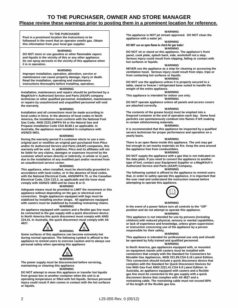
TO THE PURCHASER, OWNER AND STORE MANAGERPlease review these warnings prior to posting them in a prominent location for reference.
L25-055 Rev. 0 (05/12)2
TO THE PURCHASERPost in a prominent location the instructions to befolloweed in the event that an operator smells gas. Obtainthis information from your local gas supplier.
WARNINGDO NOT store or use gasoline or other flammable vaporsand liquids in the vicinity of this or any other appliance.Do not spray aerosols in the vicinity of this appliance whenit is in operation.
WARNINGImproper installation, operation, alteration, service ormaintenance can cause property damage, injury or death.Read the installation, operating and maintenanceinstructions thoroughly before installing, operation,
WARNINGInstallation, maintenance and repairs should be performed by aMagiKitch’n Authorized Service and Parts (ASAP) companytechnician or other qualified personnel. Installation, maintenanceor repairs by unauthorized and unqualified personnel will voidthe warranty.
WARNINGInstallation and all connections must be made according tolocal codes in force. In the absence of local codes in NorthAmerica, the installation must conform with the National FuelGas Code, ANSI Z223.1/NFPA 54 or the Natural Gas andPropane Installation Code CSA B149.1 as applicable. InAustralia, the appliance must installed in compliance withAS/NZS 5601.
WARNINGDuring the warranty period if a customer elects to use a non-original part or modifies an original part purchased from Pitcoand/or its Authorized Service and Parts (ASAP) companies, thiswarranty will be void. In addition, Pitco and its affiliates will notbe liable for any claims, damages or expenses incurred by thecustomer which arises directly or indirectly, in whole or in part,due to the installation of any modified part and/or received froman unauthorized service center.
WARNINGThis appliance, when installed, must be electrically grounded inaccordance with local codes, or in the absence of local codes,with the National Electrical Code, ANSI/NFPA 70, or the CanadianElectrical Code, CSA C22.2, as applicable and the hose mustcomply with AS/NZS 1869 and be class B or D.
WARNINGAdequate means must be provided to LIMIT the movement or thisappliance without depending on the gas or electrical cordconnection. Single appliances equipped with legs must bestabilized by installing anchor straps. All appliances equippedwith casters must be stabilized by installing restraining chains.
WARNINGAn appliance equipped with casters and a flexible gas line mustbe connected to the gas supply with a quick disconnect device.In North America this quick disconnect must comply with ANSIZ24.41. In Australia, the quick disconnect must comply with AS4627.
WARNINGSome surfaces of this appliance can become extremely hotduring normal operation. The following symbol is affixed to theappliance to remind users to exercise caution and to always usepersonal safety when operating this appliance
WARNINGThe power supply must be disconnected before servicing,maintaining or cleaning this appliance.
WARNINGDO NOT attempt to move this appliance or transfer hot liquidsfrom grease box to another container when the unit is atoperating temperature or filled with hot liquids. Serious personalinjury could result if skin comes in contact with the hot surfacesor liquids.
WARNINGThe appliance is NOT jet stream approved. DO NOT clean theappliance with a water jet.
WARNINGDO NOT use an open flame to check for gas leaks!
WARNINGDO NOT sit or stand on this appliance. The appliance’s frontpanel, cook plate, splash back, side, workshelf not a step.Serious injury could result from slipping, falling or contact withhot surfaces or liquids.
WARNINGNEVER use the appliance as a step for cleaning or accessing theventilation hood. Serious injury could result from slips, trips orfrom contacting hot surfaces or liquids.
WARNINGDO NOT use the appliance unless it is properly secured to atable, stand or freezer / refrigerated base suited to handle theweight of the entire appliance.
WARNINGThis appliance is intended for indoor use only.
WARNINGDO NOT operate appliance unless all panels and access coversare attached correctly.
WARNINGThe contents of the grease box(s) must be emptied into afireproof container at the end of operation each day. Some foodparticles can spontaneously combust into flames if left soakingin certain oil/shortening materials.
WARNINGIt is recommended that this appliance be inspected by a qualifiedservice technician for proper performance and operation on ayearly basis.
WARNINGThere is an open flame inside this appliance. The unit may gethot enough to set nearby materials on fire. Keep the area aroundthe appliance free from combustibles.
WARNINGDO NOT supply the appliance with a gas that is not indicated onthe data plate. If you need to convert the appliance to anothertype of fuel, contact your Equipment Supplier or a MagiKitch’nAuthorized Service and Parts (ASAP) Company.
WARNINGThe following symbol is affixed to the appliance to remind usersthat, in order to safely operate this appliance, it is important thatthe user read and understand the instruction manual beforeattempting to operate this appliance.
WARNINGIn the event of a power failure turn all controls to the “Off”position and do not attempt to operate this appliance.
WARNINGThis appliance is not intended for use by persons (includingchildren) with reduced physical, sensory or mental capabilities,or lack of experience and knowledge, unless given supervisionor instruction concerning use of the appliance by a personresponsible for their safety.
WARNINGThis appliance is intended for professional use only and shouldbe operated by fully trained and qualified personnel.
WARNINGIn North America, gas appliances equipped with, or mountedon equipment stands with casters must be installed withconnectors that comply with the Standard for Connectors forMovable Gas Appliances, ANSI Z21.69.CSA 6.16 Latest Edition.This connection should include a quick disconnect device thatcomplies with the Standard for Quick Disconnect Devices forUse With Gas Fuel ANSI Z221.41.CSA 6.9 Latest Edition. InAustralia, an appliance equipped with casters and a flexiblegas line must be connected to the gas supply with a quickdisconnect device that complies with AS 4627 and arestraining cable. The restraining cable must not exceed 80%of the length of the flexible gas line.
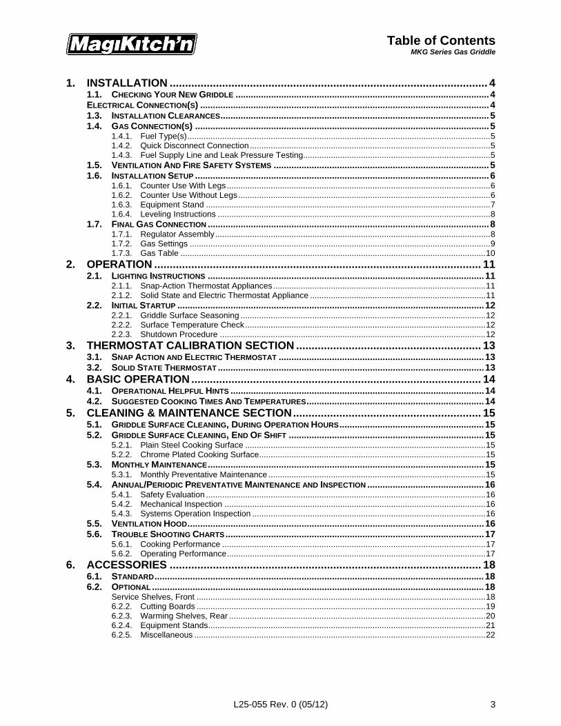
Table of ContentsMKG Series Gas Griddle
L25-055 Rev. 0 (05/12) 3
1. INSTALLATION ....................................................................................................... 41.1. CHECKING YOUR NEW GRIDDLE ....................................................................................................4ELECTRICAL CONNECTION(S) ..................................................................................................................41.3. INSTALLATION CLEARANCES..........................................................................................................51.4. GAS CONNECTION(S) ....................................................................................................................5
1.4.1. Fuel Type(s)...................................................................................................................................51.4.2. Quick Disconnect Connection ........................................................................................................51.4.3. Fuel Supply Line and Leak Pressure Testing.................................................................................5
1.5. VENTILATION AND FIRE SAFETY SYSTEMS .....................................................................................51.6. INSTALLATION SETUP ....................................................................................................................6
1.6.1. Counter Use With Legs..................................................................................................................61.6.2. Counter Use Without Legs .............................................................................................................61.6.3. Equipment Stand ...........................................................................................................................71.6.4. Leveling Instructions ......................................................................................................................8
1.7. FINAL GAS CONNECTION ...............................................................................................................81.7.1. Regulator Assembly.......................................................................................................................81.7.2. Gas Settings ..................................................................................................................................91.7.3. Gas Table ....................................................................................................................................10
2. OPERATION .......................................................................................................... 112.1. LIGHTING INSTRUCTIONS .............................................................................................................11
2.1.1. Snap-Action Thermostat Appliances............................................................................................112.1.2. Solid State and Electric Thermostat Appliance ............................................................................11
2.2. INITIAL STARTUP .........................................................................................................................122.2.1. Griddle Surface Seasoning ..........................................................................................................122.2.2. Surface Temperature Check ........................................................................................................122.2.3. Shutdown Procedure ...................................................................................................................12
3. THERMOSTAT CALIBRATION SECTION ............................................................ 133.1. SNAP ACTION AND ELECTRIC THERMOSTAT .................................................................................133.2. SOLID STATE THERMOSTAT .........................................................................................................13
4. BASIC OPERATION .............................................................................................. 144.1. OPERATIONAL HELPFUL HINTS ....................................................................................................144.2. SUGGESTED COOKING TIMES AND TEMPERATURES......................................................................14
5. CLEANING & MAINTENANCE SECTION............................................................. 155.1. GRIDDLE SURFACE CLEANING, DURING OPERATION HOURS.........................................................155.2. GRIDDLE SURFACE CLEANING, END OF SHIFT .............................................................................15
5.2.1. Plain Steel Cooking Surface ........................................................................................................155.2.2. Chrome Plated Cooking Surface..................................................................................................15
5.3. MONTHLY MAINTENANCE.............................................................................................................155.3.1. Monthly Preventative Maintenance ..............................................................................................15
5.4. ANNUAL/PERIODIC PREVENTATIVE MAINTENANCE AND INSPECTION ..............................................165.4.1. Safety Evaluation .........................................................................................................................165.4.2. Mechanical Inspection .................................................................................................................165.4.3. Systems Operation Inspection .....................................................................................................16
5.5. VENTILATION HOOD.....................................................................................................................165.6. TROUBLE SHOOTING CHARTS......................................................................................................17
5.6.1. Cooking Performance ..................................................................................................................175.6.2. Operating Performance................................................................................................................17
6. ACCESSORIES ..................................................................................................... 186.1. STANDARD..................................................................................................................................186.2. OPTIONAL ...................................................................................................................................18
Service Shelves, Front .............................................................................................................................186.2.2. Cutting Boards .............................................................................................................................196.2.3. Warming Shelves, Rear ...............................................................................................................206.2.4. Equipment Stands........................................................................................................................216.2.5. Miscellaneous ..............................................................................................................................22

InstallationMKG Series Gas Griddle
L25-055 Rev. 0 (05/12)4
WARNINGIf the appliance is equipped with a power cord and it is damaged, it must be replaced by a
MagiKitch’n Authorized Service and Parts (ASAP) company technician, or a similarly qualifiedperson in order to avoid a hazard. A replacement, oil resistant cord must be provided by the
manufacturer.
WARNINGThe electrical connection used by this appliance must comply with local codes. If there are no
local codes that apply, refer to the National Electrical Code (NEC), ANSI/NFPA 70 forinstallation in the US. In Canada, refer to CSA Standard C22.2 and local codes. In all other
cases, refer to local and national codes and regulations.
WARNINGThis equipment must be installed so that the plug is accessible unless other means for
disconnection from the power supply (e.g. a circuit breaker) is provided.
WARNINGIf your appliance uses line current, it is equipped with an oil proof, electrical supply cord with athree-prong safety plug. This is to protect operators from electrical shock hazard in the event
of an equipment malfunction. DO NOT cut or remove the grounding (third) prong from thisplug; it should be plugged into a properly grounded three-prong receptacle.
CAUTIONConnecting the appliance to an electrical supply other than that indicated on the data plate.
may damage the appliance and void the warranty.
Figure 1
1. Installation
1.1. Checking Your New GriddleYour new MagiKitch’n appliance has been carefully packed into one crate. Every effort has been made toensure that it is delivered to you in perfect condition. As you unpack your new appliance, inspect each ofthe pieces for damage. If something is damaged, DO NOT sign the bill of lading. Contact the shipperimmediately; the shipper is only responsible for 15 days after delivery. Check the packing list enclosedwith your appliance to ensure that you have received all the parts to the appliance. If you are missing anyparts, contact the dealer from whom the appliance was purchased.Locate the MagiKitch’n Model Number and Serial Number from the information plate on the inside wall,see Figure 1. Write this information and the date the appliance was purchased on the front of this manual.
If you have completed the abovesteps that are applicable to the applianceyou purchased, the appliance is nowready to be installed. Although it may bepossible for you to install and set up yournew appliance, it is STRONGLY advisedthat you have this done by qualifiedservice professionals. A qualifiedprofessional will ensure that theinstallation is safe and meets localbuilding and fire codes.
1.2. Electrical Connection(s)It is advised that this appliance beplugged into a wall receptacle that iscontrolled by the ventilation control. This will prevent the appliance from being operated without theventilator on. A schematic is behind the front access panel. The power requirements are listed below.
North America InternationalInput Voltage 120 Vac 50/60 Hz 220,230, or 240 Vac 50/60 Hz
Current/Control 0.22 Amps 0.11 Amps
Electrical Requirements
InstallationMKG Series Gas Griddle
L25-055 Rev. 0 (05/12) 5
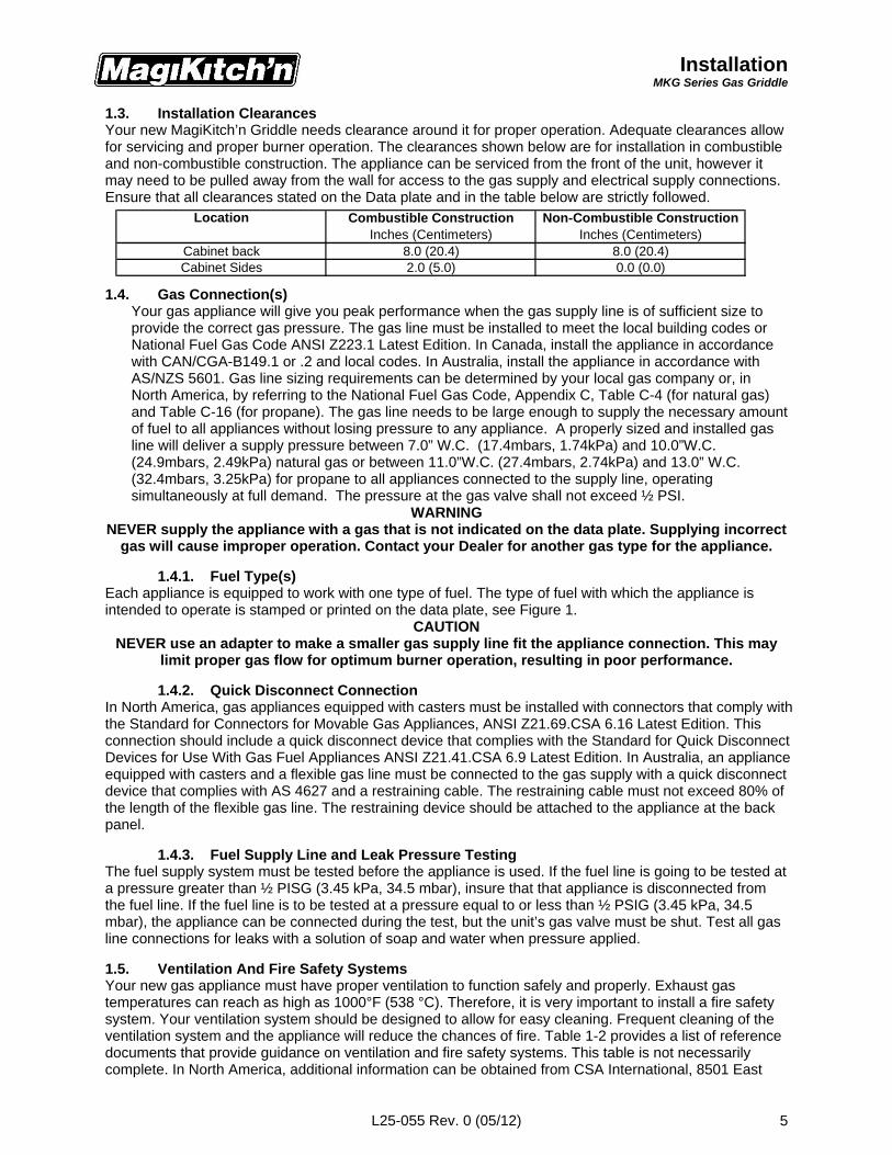
Location Combustible ConstructionInches (Centimeters)
Non-Combustible ConstructionInches (Centimeters)
Cabinet back 8.0 (20.4) 8.0 (20.4)Cabinet Sides 2.0 (5.0) 0.0 (0.0)
1.3. Installation ClearancesYour new MagiKitch’n Griddle needs clearance around it for proper operation. Adequate clearances allowfor servicing and proper burner operation. The clearances shown below are for installation in combustibleand non-combustible construction. The appliance can be serviced from the front of the unit, however itmay need to be pulled away from the wall for access to the gas supply and electrical supply connections.Ensure that all clearances stated on the Data plate and in the table below are strictly followed.
1.4. Gas Connection(s)Your gas appliance will give you peak performance when the gas supply line is of sufficient size toprovide the correct gas pressure. The gas line must be installed to meet the local building codes orNational Fuel Gas Code ANSI Z223.1 Latest Edition. In Canada, install the appliance in accordancewith CAN/CGA-B149.1 or .2 and local codes. In Australia, install the appliance in accordance withAS/NZS 5601. Gas line sizing requirements can be determined by your local gas company or, inNorth America, by referring to the National Fuel Gas Code, Appendix C, Table C-4 (for natural gas)and Table C-16 (for propane). The gas line needs to be large enough to supply the necessary amountof fuel to all appliances without losing pressure to any appliance. A properly sized and installed gasline will deliver a supply pressure between 7.0” W.C. (17.4mbars, 1.74kPa) and 10.0”W.C.(24.9mbars, 2.49kPa) natural gas or between 11.0”W.C. (27.4mbars, 2.74kPa) and 13.0” W.C.(32.4mbars, 3.25kPa) for propane to all appliances connected to the supply line, operatingsimultaneously at full demand. The pressure at the gas valve shall not exceed ½ PSI.
WARNINGNEVER supply the appliance with a gas that is not indicated on the data plate. Supplying incorrect
gas will cause improper operation. Contact your Dealer for another gas type for the appliance.
1.4.1. Fuel Type(s)Each appliance is equipped to work with one type of fuel. The type of fuel with which the appliance isintended to operate is stamped or printed on the data plate, see Figure 1.
CAUTIONNEVER use an adapter to make a smaller gas supply line fit the appliance connection. This may
limit proper gas flow for optimum burner operation, resulting in poor performance.
1.4.2. Quick Disconnect ConnectionIn North America, gas appliances equipped with casters must be installed with connectors that comply withthe Standard for Connectors for Movable Gas Appliances, ANSI Z21.69.CSA 6.16 Latest Edition. Thisconnection should include a quick disconnect device that complies with the Standard for Quick DisconnectDevices for Use With Gas Fuel Appliances ANSI Z21.41.CSA 6.9 Latest Edition. In Australia, an applianceequipped with casters and a flexible gas line must be connected to the gas supply with a quick disconnectdevice that complies with AS 4627 and a restraining cable. The restraining cable must not exceed 80% ofthe length of the flexible gas line. The restraining device should be attached to the appliance at the backpanel.
1.4.3. Fuel Supply Line and Leak Pressure TestingThe fuel supply system must be tested before the appliance is used. If the fuel line is going to be tested ata pressure greater than ½ PISG (3.45 kPa, 34.5 mbar), insure that that appliance is disconnected fromthe fuel line. If the fuel line is to be tested at a pressure equal to or less than ½ PSIG (3.45 kPa, 34.5mbar), the appliance can be connected during the test, but the unit’s gas valve must be shut. Test all gasline connections for leaks with a solution of soap and water when pressure applied.
1.5. Ventilation And Fire Safety SystemsYour new gas appliance must have proper ventilation to function safely and properly. Exhaust gastemperatures can reach as high as 1000°F (538 °C). Therefore, it is very important to install a fire safetysystem. Your ventilation system should be designed to allow for easy cleaning. Frequent cleaning of theventilation system and the appliance will reduce the chances of fire. Table 1-2 provides a list of referencedocuments that provide guidance on ventilation and fire safety systems. This table is not necessarilycomplete. In North America, additional information can be obtained from CSA International, 8501 East
InstallationMKG Series Gas Griddle
L25-055 Rev. 0 (05/12)6
Figure 2
Figure 3
Pleasant Valley Rd., Cleveland, OH 44131. In Australia, the ventilation system must comply with AS/NZS5601.1.
CAUTIONExcessive ventilation causes drafts, which will interfere with the operation of the appliance. Leave
at least 18 inches of open space between the flue opening and the intake of the exhaust hood.CAUTION
Ensure that your ventilation system does not cause a down draft at the appliance’s flue opening.Down drafts will not allow the appliance to exhaust properly and will cause overheating which
may cause permanent damage. Damage caused by down drafts will not be covered underequipment warranty. NEVER allow anything to obstruct the flow of combustibles or ventilation
exiting the appliance flue.1.6. Installation SetupThe installation of this appliance MUST conform tolocal codes. In the absence of local codes in NorthAmerica, the installation must conform with theNational Fuel Gas Code, ANSI Z223.1/NFPA 54 orthe Natural Gas and Propane Installation CodeCSA B149.1 as applicable. In Australia, theappliance must installed in compliance withAS/NZS 5601 (current revision).To Start uncrate appliance and locate installationaccessories.
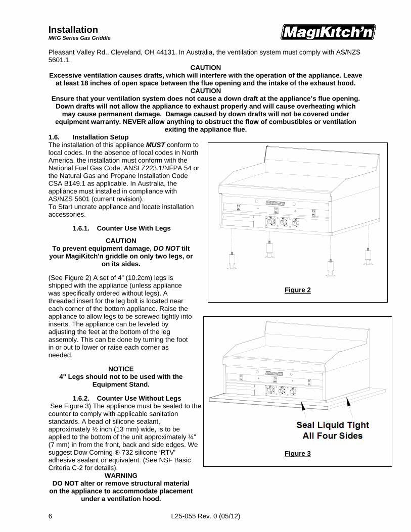
1.6.1. Counter Use With Legs
CAUTIONTo prevent equipment damage, DO NOT tilt
your MagiKitch'n griddle on only two legs, oron its sides.
(See Figure 2) A set of 4” (10.2cm) legs isshipped with the appliance (unless appliancewas specifically ordered without legs). Athreaded insert for the leg bolt is located neareach corner of the bottom appliance. Raise theappliance to allow legs to be screwed tightly intoinserts. The appliance can be leveled byadjusting the feet at the bottom of the legassembly. This can be done by turning the footin or out to lower or raise each corner asneeded.
NOTICE4" Legs should not to be used with the
Equipment Stand.
1.6.2. Counter Use Without Legs See Figure 3) The appliance must be sealed to thecounter to comply with applicable sanitationstandards. A bead of silicone sealant,approximately ½ inch (13 mm) wide, is to beapplied to the bottom of the unit approximately ¼”(7 mm) in from the front, back and side edges. Wesuggest Dow Corning ® 732 silicone ‘RTV’adhesive sealant or equivalent. (See NSF BasicCriteria C-2 for details).
WARNINGDO NOT alter or remove structural material
on the appliance to accommodate placementunder a ventilation hood.
InstallationMKG Series Gas Griddle
L25-055 Rev. 0 (05/12) 7
BRACKET (2)
MOUNT FLUSHTO FRONT
(SUPPLIED)
(SUPPLIED)
NUTS & BOLTSINCLUDED
WITH STAND
REAR
Figure 4
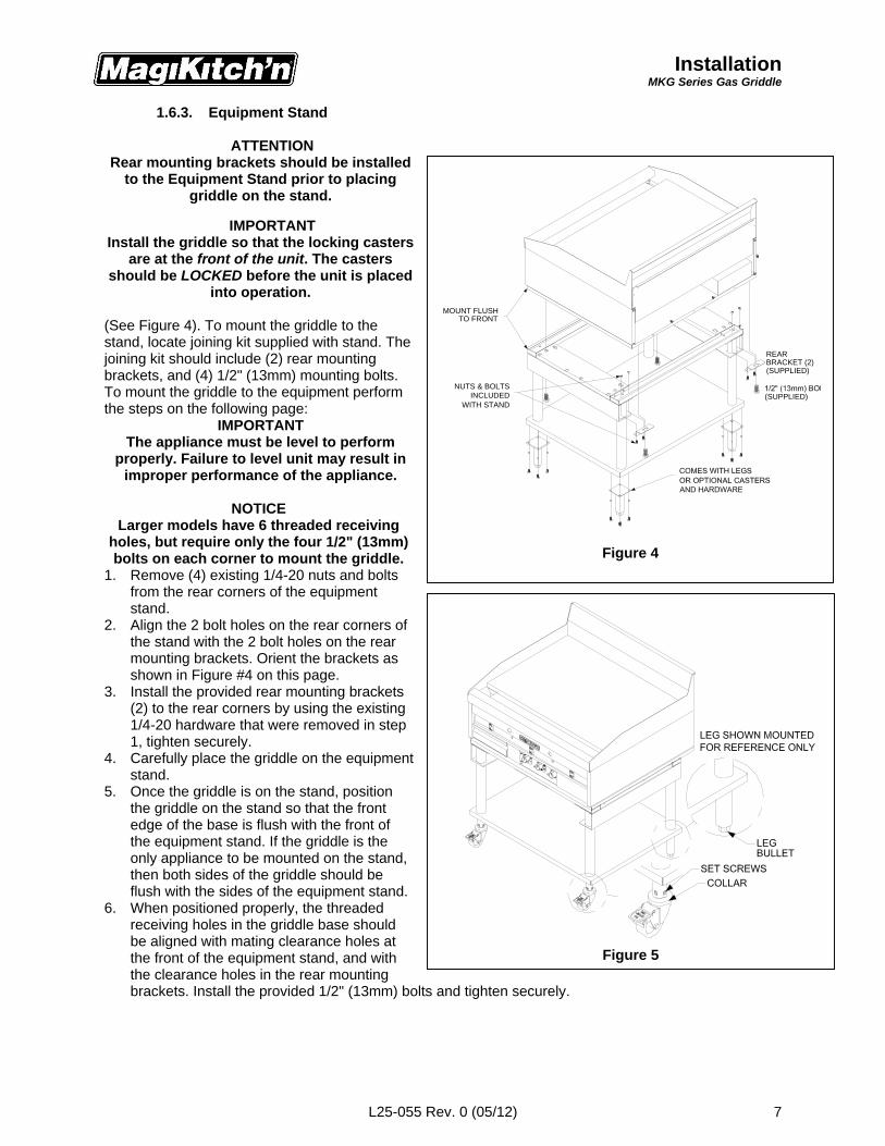
1.6.3. Equipment Stand
ATTENTIONRear mounting brackets should be installed
to the Equipment Stand prior to placinggriddle on the stand.
IMPORTANTInstall the griddle so that the locking casters
are at the front of the unit. The castersshould be LOCKED before the unit is placed
into operation.
(See Figure 4). To mount the griddle to thestand, locate joining kit supplied with stand. Thejoining kit should include (2) rear mountingbrackets, and (4) 1/2" (13mm) mounting bolts.To mount the griddle to the equipment performthe steps on the following page:
IMPORTANTThe appliance must be level to perform
properly. Failure to level unit may result inimproper performance of the appliance.
NOTICELarger models have 6 threaded receiving
holes, but require only the four 1/2" (13mm)bolts on each corner to mount the griddle.
1. Remove (4) existing 1/4-20 nuts and boltsfrom the rear corners of the equipmentstand.
2. Align the 2 bolt holes on the rear corners ofthe stand with the 2 bolt holes on the rearmounting brackets. Orient the brackets asshown in Figure #4 on this page.
3. Install the provided rear mounting brackets(2) to the rear corners by using the existing1/4-20 hardware that were removed in step1, tighten securely.
4. Carefully place the griddle on the equipmentstand.
5. Once the griddle is on the stand, positionthe griddle on the stand so that the frontedge of the base is flush with the front ofthe equipment stand. If the griddle is theonly appliance to be mounted on the stand,then both sides of the griddle should beflush with the sides of the equipment stand.
6. When positioned properly, the threadedreceiving holes in the griddle base shouldbe aligned with mating clearance holes atthe front of the equipment stand, and withthe clearance holes in the rear mountingbrackets. Install the provided 1/2" (13mm) bolts and tighten securely.
Figure 5
InstallationMKG Series Gas Griddle
L25-055 Rev. 0 (05/12)8
1.6.4. Leveling InstructionsNOTICE
Equipment stands are shipped from the factory with the legs or casters set to the minimum heightadjustment. Units should be leveled at time of installation, failure to do so could cause the griddle to
operate improperly.
1. Identify the corner of the stand that needs to be adjusted, remove the weight load from the corner to beleveled.
2. Legs- using a wrench, or pliers turn the leg bullet, See Figure 5, CCW to raise the height of the equipmentstand. There is ½” (13mm) to ¾” (19mm) of adjustment.Casters- Using a Flat Head screwdriver, loosen the set screws of the caster to be leveled, See Figure5.Turn the collar of the caster CCW to raise the height of the equipment stand. There is ¾” (19mm) ofadjustment.After leveling adjustment is complete, re-tighten set screws.
3. Check the levelness of the equipment, if necessary Repeat steps 1 and 2.NOTICE
This appliance may only be installed with casters provided by the manufacturer. When installed withcasters in North America, a gas connection complying with ANSI Z21.69/CGA-6.16 and a quick disconnectdevice complying with ANSI Z21.41/CAN 1-6.9. It must also be installed with a restraining device to guard
against putting any strain on the gas connections when the unit is moved. In Australia the quickdisconnect device must comply with AS4627. The restraining device must not exceed 80% of the length
of the flexible gas line.1.7. Final Gas Connection
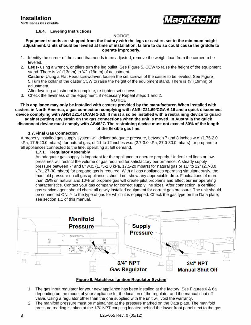
A properly installed gas supply system will deliver adequate pressure, between 7 and 8 inches w.c. (1.75-2.0kPa, 17.5-20.0 mbars) for natural gas, or 11 to 12 inches w.c. (2.7-3.0 kPa, 27.0-30.0 mbars) for propane toall appliances connected to the line, operating at full demand.
1.7.1. Regulator AssemblyAn adequate gas supply is important for the appliance to operate properly. Undersized lines or low-pressures will restrict the volume of gas required for satisfactory performance. A steady supplypressure between 7” and 8” w.c. (1.75-2.0 kPa, 17.5-20 mbars) for natural gas or 11” to 12” (2.7-3.0kPa, 27-30 mbars) for propane gas is required. With all gas appliances operating simultaneously, themanifold pressure on all gas appliances should not show any appreciable drop. Fluctuations of morethan 25% on natural and 10% on propane gas will create pilot problems and affect burner operatingcharacteristics. Contact your gas company for correct supply line sizes. After connection, a certifiedgas service agent should check all newly installed equipment for correct gas pressure. The unit shouldbe connected ONLY to the type of gas for which it is equipped. Check the gas type on the Data plate;see section 1.1 of this manual.
Figure 6, Matchless Ignition Regulator System
1. The gas input regulator for your new appliance has been installed at the factory, See Figures 6 & 6adepending on the model of your appliance for the location of the regulator and the manual shut offvalve. Using a regulator other than the one supplied with the unit will void the warranty.
2. The manifold pressure must be maintained at the pressure marked on the Data plate. The manifoldpressure reading is taken at the 1/8” NPT coupling located behind the lower front panel next to the gas
InstallationMKG Series Gas Griddle
L25-055 Rev. 0 (05/12) 9
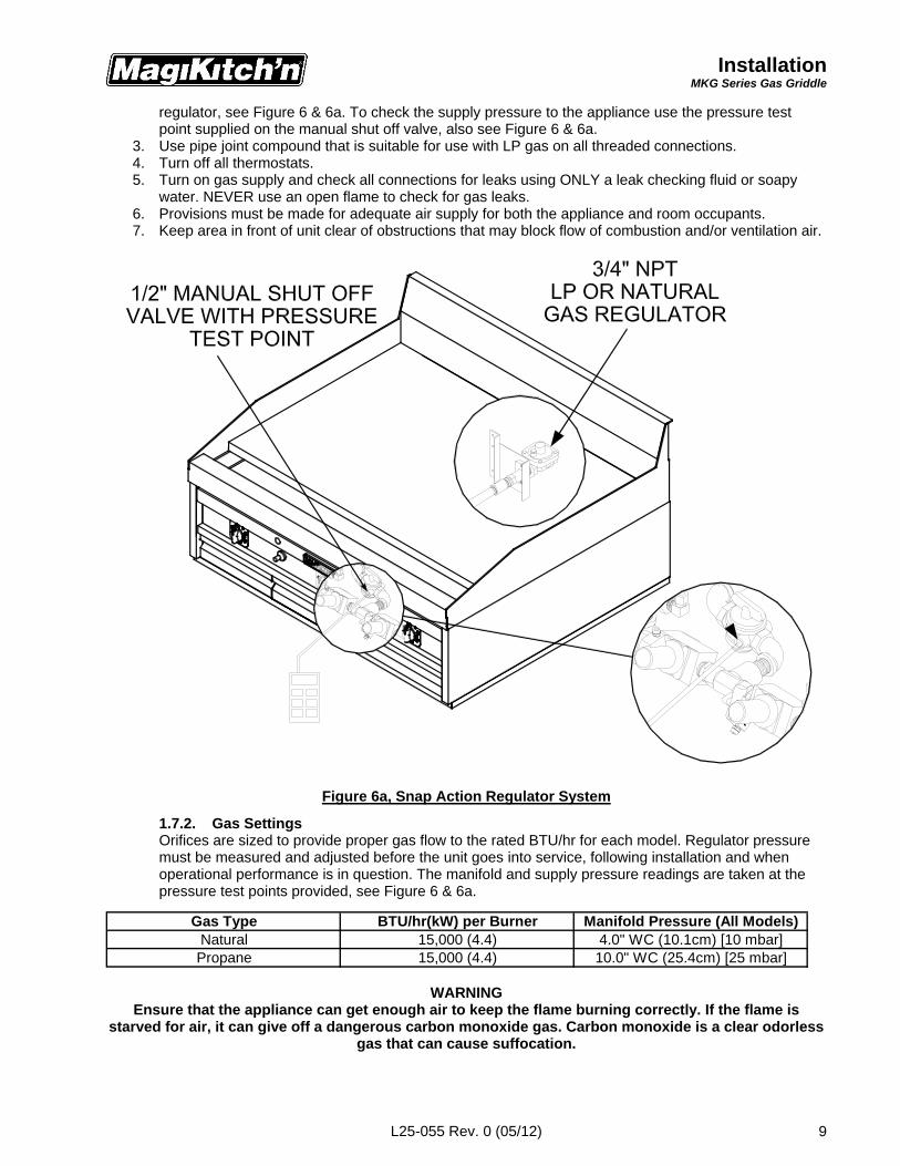
regulator, see Figure 6 & 6a. To check the supply pressure to the appliance use the pressure testpoint supplied on the manual shut off valve, also see Figure 6 & 6a.
3. Use pipe joint compound that is suitable for use with LP gas on all threaded connections.4. Turn off all thermostats.5. Turn on gas supply and check all connections for leaks using ONLY a leak checking fluid or soapy
water. NEVER use an open flame to check for gas leaks.6. Provisions must be made for adequate air supply for both the appliance and room occupants.7. Keep area in front of unit clear of obstructions that may block flow of combustion and/or ventilation air.
Figure 6a, Snap Action Regulator System
1.7.2. Gas SettingsOrifices are sized to provide proper gas flow to the rated BTU/hr for each model. Regulator pressuremust be measured and adjusted before the unit goes into service, following installation and whenoperational performance is in question. The manifold and supply pressure readings are taken at thepressure test points provided, see Figure 6 & 6a.
WARNINGEnsure that the appliance can get enough air to keep the flame burning correctly. If the flame is
starved for air, it can give off a dangerous carbon monoxide gas. Carbon monoxide is a clear odorlessgas that can cause suffocation.
Gas Type BTU/hr(kW) per Burner Manifold Pressure (All Models)Natural 15,000 (4.4) 4.0" WC (10.1cm) [10 mbar]Propane 15,000 (4.4) 10.0" WC (25.4cm) [25 mbar]
OperationsMKG Series Gas Griddle
L25-055 Rev. 0 (05/12)10
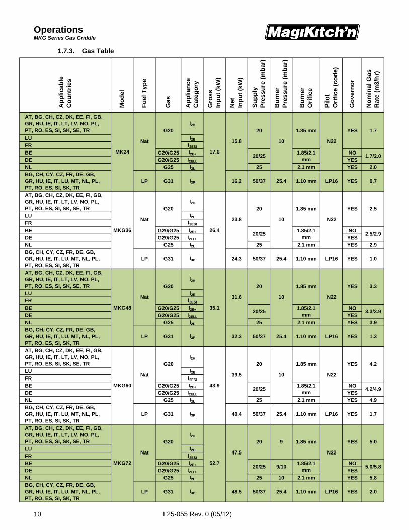
1.7.3. Gas Table
AT, BG, CH, CZ, DK, EE, FI, GB,GR, HU, IE, IT, LT, LV, NO, PL,PT, RO, ES, SI, SK, SE, TR
I2H
LU I2E
FR I2ESI
BE G20/G25 I2E+ NODE G20/G25 I2ELL YESNL G25 I2L 25 2.1 mm YES 2.0
BG, CH, CY, CZ, FR, DE, GB,GR, HU, IE, IT, LU, MT, NL, PL,PT, RO, ES, SI, SK, TR
LP G31 I3P 16.2 50/37 25.4 1.10 mm LP16 YES 0.7
AT, BG, CH, CZ, DK, EE, FI, GB,GR, HU, IE, IT, LT, LV, NO, PL,PT, RO, ES, SI, SK, SE, TR
I2H
LU I2E
FR I2ESI
BE G20/G25 I2E+ NODE G20/G25 I2ELL YESNL G25 I2L 25 2.1 mm YES 2.9
BG, CH, CY, CZ, FR, DE, GB,GR, HU, IE, IT, LU, MT, NL, PL,PT, RO, ES, SI, SK, TR
LP G31 I3P 24.3 50/37 25.4 1.10 mm LP16 YES 1.0
AT, BG, CH, CZ, DK, EE, FI, GB,GR, HU, IE, IT, LT, LV, NO, PL,PT, RO, ES, SI, SK, SE, TR
I2H
LU I2E
FR I2ESI
BE G20/G25 I2E+ NODE G20/G25 I2ELL YESNL G25 I2L 25 2.1 mm YES 3.9
BG, CH, CY, CZ, FR, DE, GB,GR, HU, IE, IT, LU, MT, NL, PL,PT, RO, ES, SI, SK, TR
LP G31 I3P 32.3 50/37 25.4 1.10 mm LP16 YES 1.3
AT, BG, CH, CZ, DK, EE, FI, GB,GR, HU, IE, IT, LT, LV, NO, PL,PT, RO, ES, SI, SK, SE, TR
I2H
LU I2E
FR I2ESI
BE G20/G25 I2E+ NODE G20/G25 I2ELL YESNL G25 I2L 25 2.1 mm YES 4.9
BG, CH, CY, CZ, FR, DE, GB,GR, HU, IE, IT, LU, MT, NL, PL,PT, RO, ES, SI, SK, TR
LP G31 I3P 40.4 50/37 25.4 1.10 mm LP16 YES 1.7
AT, BG, CH, CZ, DK, EE, FI, GB,GR, HU, IE, IT, LT, LV, NO, PL,PT, RO, ES, SI, SK, SE, TR
I2H
LU I2E
FR I2ESI
BE G20/G25 I2E+ NODE G20/G25 I2ELL YESNL G25 I2L 25 10 2.1 mm YES 5.8
BG, CH, CY, CZ, FR, DE, GB,GR, HU, IE, IT, LU, MT, NL, PL,PT, RO, ES, SI, SK, TR
LP G31 I3P 48.5 50/37 25.4 1.10 mm LP16 YES 2.0
Nat
G20
MKG48 35.1
MKG60 43.9
MKG72 52.7
YES
1.85 mm YES 1.7
N22
1.7/2.0
10
1.85/2.1 mm
A
pp
lica
ble
Co
un
trie
s
Nat
20
20/25MK24 17.6
15.8
G
as
A
pp
lia
nce
C
ate
go
ry
G
ros
s
Inp
ut
(kW
)
N
om
ina
l G
as
R
ate
(m
3/h
r)
M
od
el
F
uel
Typ
e
N
et
In
pu
t (k
W)
S
up
ply
P
res
su
re (
mb
ar)
B
urn
er
P
res
su
re (
mb
ar)
B
urn
er
O
rifi
ce
P
ilo
t
Ori
fic
e (c
od
e)
G
ove
rno
r
MKG36 26.4
Nat
G20
G20
G20
Nat
Nat
G20
39.5
20
20/25
2.5
1.85/2.1 mm
2.5/2.9
31.6 10 N22
YES1.85 mm
23.8 10
1.85 mm
N22
YES 4.2
1.85/2.1 mm
4.2/4.9
N22
20
20/25
20
20/25
10
1.85 mm
1.85/2.1 mm
3.3
3.3/3.9
5.0
47.5
20/25 9/101.85/2.1
mm5.0/5.8
20 9 1.85 mm
N22
YES
OperationsMKG Series Gas Griddle
L25-055 Rev. 0 (05/12) 11
2. OperationEnsure that a proper installation has been performed on the appliance and that all warnings, cautions, andnotices contained in this manual have been read, understood and adhered to before proceeding.
2.1. Lighting Instructions
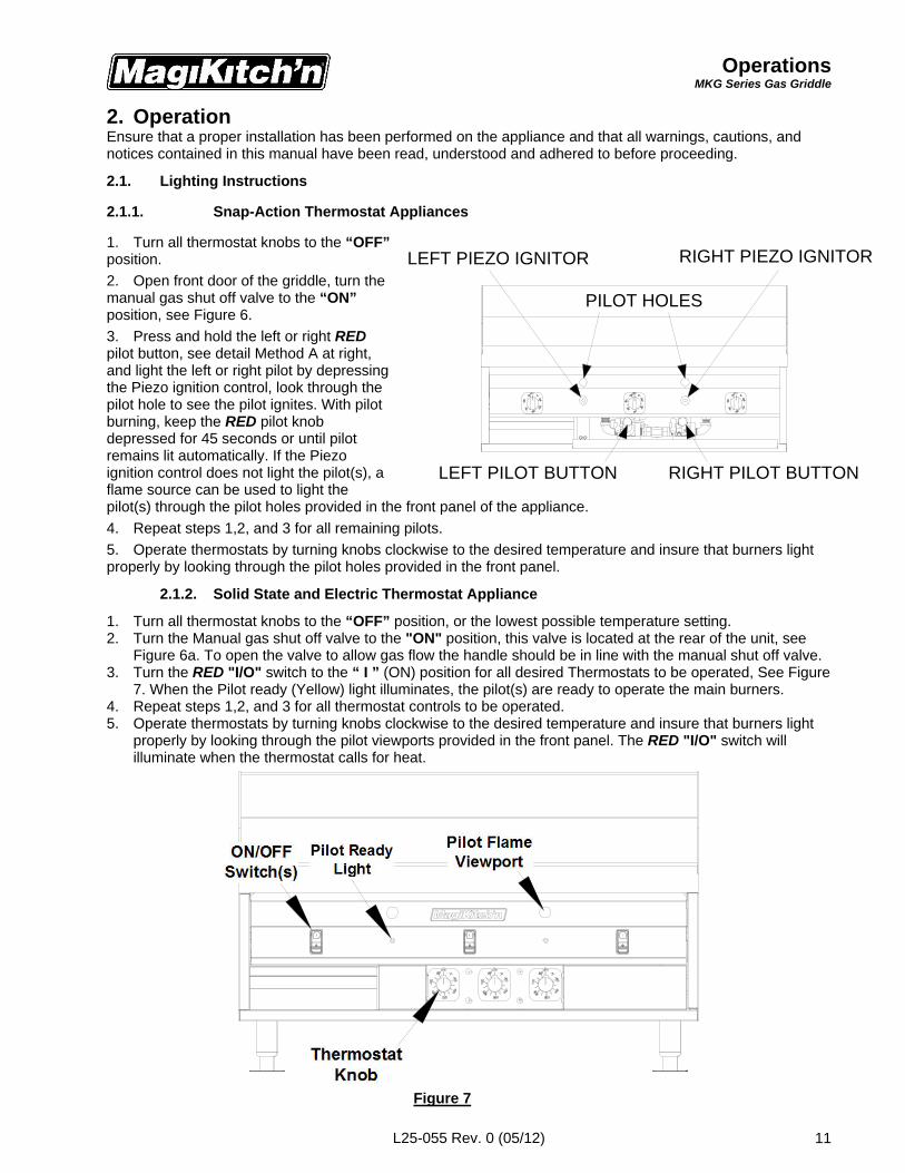
2.1.1. Snap-Action Thermostat Appliances
1. Turn all thermostat knobs to the “OFF”position.
2. Open front door of the griddle, turn themanual gas shut off valve to the “ON”position, see Figure 6.
3. Press and hold the left or right REDpilot button, see detail Method A at right,and light the left or right pilot by depressingthe Piezo ignition control, look through thepilot hole to see the pilot ignites. With pilotburning, keep the RED pilot knobdepressed for 45 seconds or until pilotremains lit automatically. If the Piezoignition control does not light the pilot(s), aflame source can be used to light thepilot(s) through the pilot holes provided in the front panel of the appliance.
4. Repeat steps 1,2, and 3 for all remaining pilots.
5. Operate thermostats by turning knobs clockwise to the desired temperature and insure that burners lightproperly by looking through the pilot holes provided in the front panel.
2.1.2. Solid State and Electric Thermostat Appliance
1. Turn all thermostat knobs to the “OFF” position, or the lowest possible temperature setting.2. Turn the Manual gas shut off valve to the "ON" position, this valve is located at the rear of the unit, see
Figure 6a. To open the valve to allow gas flow the handle should be in line with the manual shut off valve.3. Turn the RED "I/O" switch to the “ I ” (ON) position for all desired Thermostats to be operated, See Figure
7. When the Pilot ready (Yellow) light illuminates, the pilot(s) are ready to operate the main burners.4. Repeat steps 1,2, and 3 for all thermostat controls to be operated.5. Operate thermostats by turning knobs clockwise to the desired temperature and insure that burners light
properly by looking through the pilot viewports provided in the front panel. The RED "I/O" switch willilluminate when the thermostat calls for heat.
Figure 7
LEFT PIEZO IGNITOR RIGHT PIEZO IGNITOR
LEFT PILOT BUTTON RIGHT PILOT BUTTON
PILOT HOLES
OperationsMKG Series Gas Griddle
L25-055 Rev. 0 (05/12)12
CAUTIONIf Pilot Ready light(s) does not illuminate, Turn all Thermostat "I/O" switches for that pilot to
“O”(OFF), wait five minutes before attempting to re-light.WARNING
If the gas supply and/or the electrical power is interrupted, or if pilot(s) extinguish, turn thethermostat knobs and the gas shut off valve to the "OFF" position and wait five (5) minutes
before attempting to re-light the pilot. Do not attempt to operate this appliance during a powerfailure.
2.2. Initial StartupNOTICE
New griddles should be carefully tempered and cared for in order to avoid possible damage.
Wipe the griddle surface clean. A mild soapy water solution may be used to clean the surface, be sure to rinsecooking surface thoroughly with fresh water to eliminate any soap residue. It is also important to wipe thegriddle surface and surrounding areas to dry up any standing water. Never allow water on a hot griddlesurface.
Seasoning is not required on a Chrome Plated Cooking surface, but the following procedure may beperformed to improve the non-stick qualities of the chrome plated cooking surface.
2.2.1. Griddle Surface Seasoning1. To season the griddle, Light all pilots and turn all the thermostat controls to 200°F, (93°C). As the
unit heats up to 200°F, (93°C), apply a light film of cooking oil or beef suet over the entire cookingsurface, wiping off any excess build up. This step may be repeated as necessary to apply an evencoating on the griddle surface. Seasoning will help create and maintain a non-stick cookingsurface on your griddle.
2. Allow the seasoned surface to idle for one hour at 200°F, (93°C), Then set the thermostats to yourdesired cooking temperature, once your griddle surface has reached temperature, apply anothercoating of seasoning oil, wiping off any excess that may cause build up.
2.2.2. Surface Temperature Check1. If available, place grill surface thermometer over each thermostat sensing probe 12", (30.5cm),
from the front edge of the griddle surface, See Figure 8 below. The sensing probes are located inline with the thermostat knobs on snap action models, or the ON/OFF switch(s) on matchlessignition models. Align your measuring device with the respective location on your appliance andmonitor the temperature at all the controls that are to be adjusted.
2. Heat the griddle up to the desired cooking temperature; check the surface temperature reading onthe grill thermometer. If necessary, adjust the thermostats that control any area of the surface thatare not within ± 15°F (± 8.3°C) of the thermostat setting. The procedure for adjusting thethermostats is in Section 3.
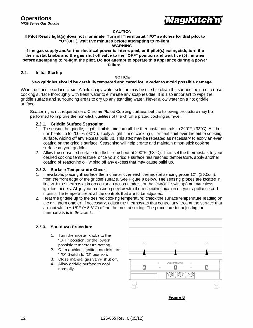
2.2.3. Shutdown Procedure
1. Turn thermostat knobs to the“OFF” position, or the lowestpossible temperature setting.
2. On matchless ignition models turn“I/O” Switch to “O” position.
3. Close manual gas valve shut off.4. Allow griddle surface to cool
normally.
Figure 8
CalibrationMKG Series Gas Griddle
L25-055 Rev. 0 (05/12) 13
220140220140
250
200
150 °C
°F
250
200 100
80
120
550
260500
280
240450
550150 °C
°F
100
80
120
500260
280
CAP LINE
240450
160300
350180 400200
350180
300160
400200
5/16" NUT
ALIGNED WITH ACTUAL TEMP.TEMP. INDICATOR IS ROTATE KNOB UNTIL
ON AND OFFTHIS CAP SNAPS
THERMOSTAT STEM
TURN CCW TO INCREASE TEMPERATURETURN CW TO DECREASE TEMPERATURE
THERMOSTAT ADJUSTMENT SCREW
ELECTRIC THERMOSTATS SHOWN FOR REFERENCE
REMOVED, SNAP ACTIONTHERMOSTAT KNOB
3. Thermostat Calibration SectionEach control typically operates a pair of burners with a Snap action, Electric or Solid State. The controls wereset at the factory. However, if the griddle’s surface temperature varies greatly from the setting on thethermostat knob, adjust the thermostat using the following procedure:
3.1. Snap Action and Electric Thermostat
1 Light pilots as described in section(s) 2.1.1 and2.1.2.
2 Turn all the control knobs to the desiredtemperature setting.
3 Wait 30 minutes (or 1 hour if griddle was cold)for surface to stabilize.
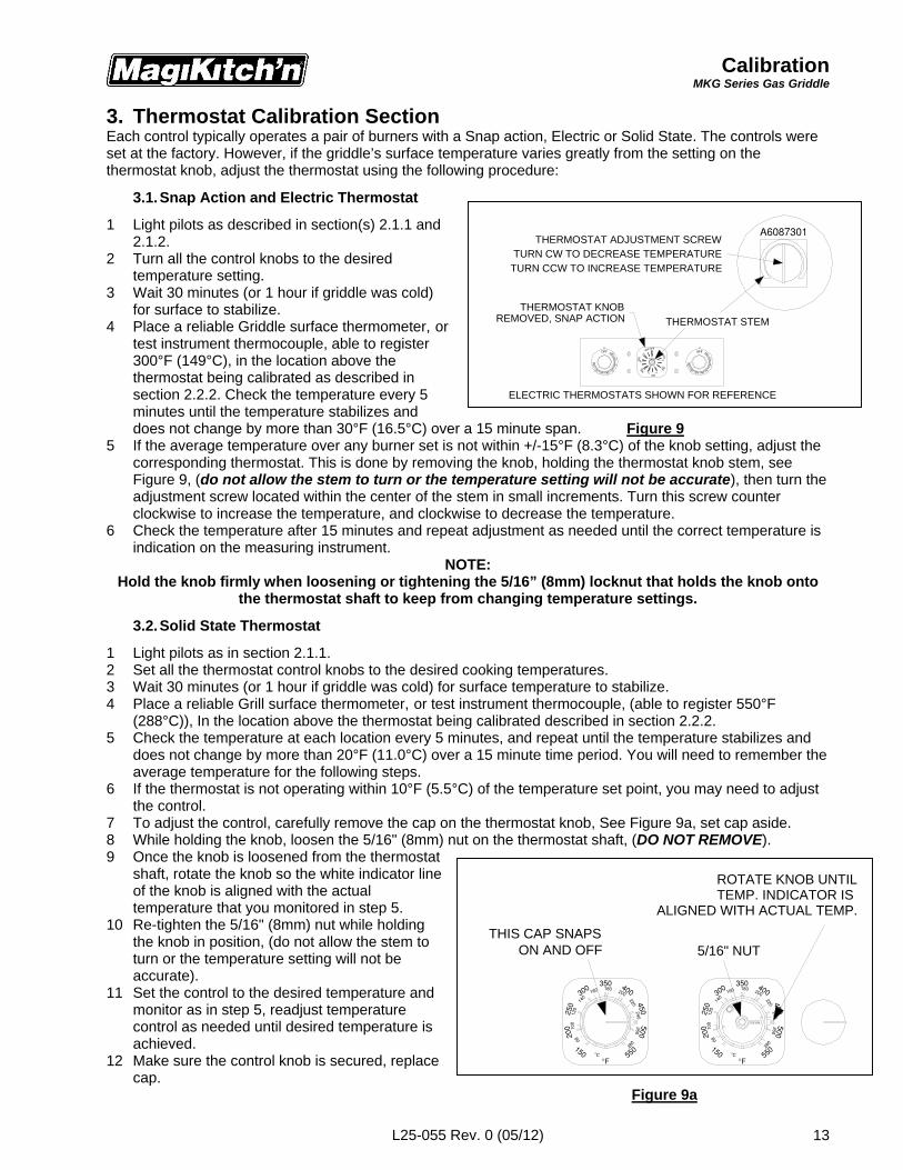
4 Place a reliable Griddle surface thermometer, ortest instrument thermocouple, able to register300°F (149°C), in the location above thethermostat being calibrated as described insection 2.2.2. Check the temperature every 5minutes until the temperature stabilizes anddoes not change by more than 30°F (16.5°C) over a 15 minute span. Figure 9
5 If the average temperature over any burner set is not within +/-15°F (8.3°C) of the knob setting, adjust thecorresponding thermostat. This is done by removing the knob, holding the thermostat knob stem, seeFigure 9, (do not allow the stem to turn or the temperature setting will not be accurate), then turn theadjustment screw located within the center of the stem in small increments. Turn this screw counterclockwise to increase the temperature, and clockwise to decrease the temperature.
6 Check the temperature after 15 minutes and repeat adjustment as needed until the correct temperature isindication on the measuring instrument.
NOTE:Hold the knob firmly when loosening or tightening the 5/16” (8mm) locknut that holds the knob onto
the thermostat shaft to keep from changing temperature settings.
3.2. Solid State Thermostat
1 Light pilots as in section 2.1.1.2 Set all the thermostat control knobs to the desired cooking temperatures.3 Wait 30 minutes (or 1 hour if griddle was cold) for surface temperature to stabilize.4 Place a reliable Grill surface thermometer, or test instrument thermocouple, (able to register 550°F
(288°C)), In the location above the thermostat being calibrated described in section 2.2.2.5 Check the temperature at each location every 5 minutes, and repeat until the temperature stabilizes and
does not change by more than 20°F (11.0°C) over a 15 minute time period. You will need to remember theaverage temperature for the following steps.
6 If the thermostat is not operating within 10°F (5.5°C) of the temperature set point, you may need to adjustthe control.
7 To adjust the control, carefully remove the cap on the thermostat knob, See Figure 9a, set cap aside.8 While holding the knob, loosen the 5/16" (8mm) nut on the thermostat shaft, (DO NOT REMOVE).9 Once the knob is loosened from the thermostat
shaft, rotate the knob so the white indicator lineof the knob is aligned with the actualtemperature that you monitored in step 5.
10 Re-tighten the 5/16" (8mm) nut while holdingthe knob in position, (do not allow the stem toturn or the temperature setting will not beaccurate).
11 Set the control to the desired temperature andmonitor as in step 5, readjust temperaturecontrol as needed until desired temperature isachieved.
12 Make sure the control knob is secured, replacecap.
Figure 9a
Basic OperationMKG Series Gas Griddle
L25-055 Rev. 0 (05/12)14
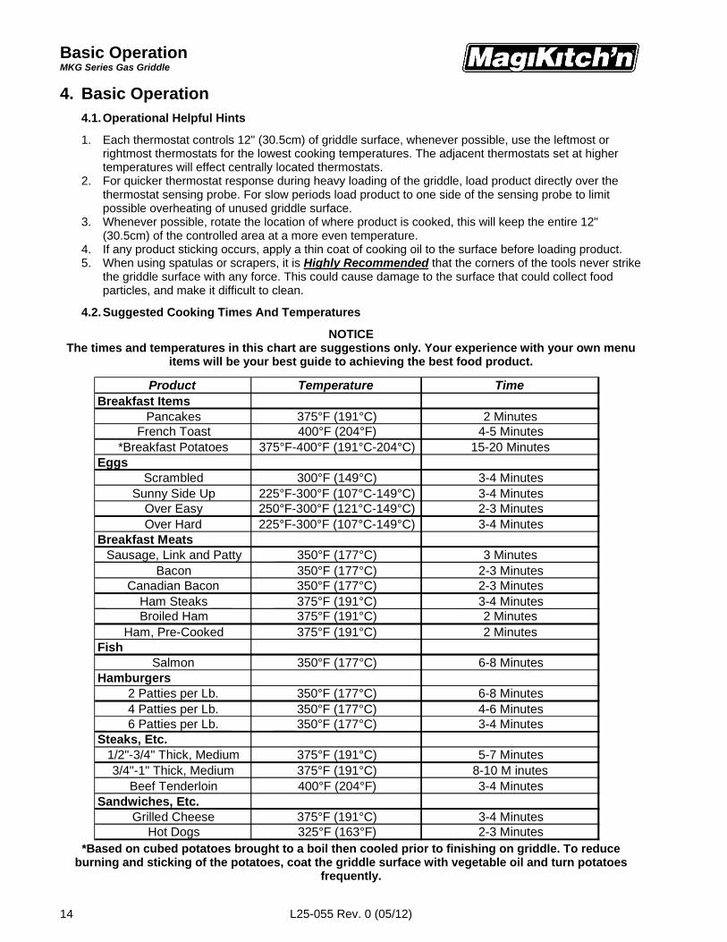
Product Temperature TimeBreakfast Items
Pancakes 375°F (191°C) 2 MinutesFrench Toast 400°F (204°F) 4-5 Minutes
*Breakfast Potatoes 375°F-400°F (191°C-204°C) 15-20 MinutesEggs
Scrambled 300°F (149°C) 3-4 MinutesSunny Side Up 225°F-300°F (107°C-149°C) 3-4 Minutes
Over Easy 250°F-300°F (121°C-149°C) 2-3 MinutesOver Hard 225°F-300°F (107°C-149°C) 3-4 Minutes
Breakfast MeatsSausage, Link and Patty 350°F (177°C) 3 Minutes
Bacon 350°F (177°C) 2-3 MinutesCanadian Bacon 350°F (177°C) 2-3 Minutes
Ham Steaks 375°F (191°C) 3-4 MinutesBroiled Ham 375°F (191°C) 2 Minutes
Ham, Pre-Cooked 375°F (191°C) 2 MinutesFish
Salmon 350°F (177°C) 6-8 MinutesHamburgers
2 Patties per Lb. 350°F (177°C) 6-8 Minutes4 Patties per Lb. 350°F (177°C) 4-6 Minutes6 Patties per Lb. 350°F (177°C) 3-4 Minutes
Steaks, Etc.1/2"-3/4" Thick, Medium 375°F (191°C) 5-7 Minutes3/4"-1" Thick, Medium 375°F (191°C) 8-10 M inutes
Beef Tenderloin 400°F (204°F) 3-4 MinutesSandwiches, Etc.
Grilled Cheese 375°F (191°C) 3-4 MinutesHot Dogs 325°F (163°F) 2-3 Minutes
4. Basic Operation4.1. Operational Helpful Hints
1. Each thermostat controls 12" (30.5cm) of griddle surface, whenever possible, use the leftmost orrightmost thermostats for the lowest cooking temperatures. The adjacent thermostats set at highertemperatures will effect centrally located thermostats.
2. For quicker thermostat response during heavy loading of the griddle, load product directly over thethermostat sensing probe. For slow periods load product to one side of the sensing probe to limitpossible overheating of unused griddle surface.
3. Whenever possible, rotate the location of where product is cooked, this will keep the entire 12"(30.5cm) of the controlled area at a more even temperature.
4. If any product sticking occurs, apply a thin coat of cooking oil to the surface before loading product.5. When using spatulas or scrapers, it is Highly Recommended that the corners of the tools never strike
the griddle surface with any force. This could cause damage to the surface that could collect foodparticles, and make it difficult to clean.
4.2. Suggested Cooking Times And Temperatures
NOTICEThe times and temperatures in this chart are suggestions only. Your experience with your own menu
items will be your best guide to achieving the best food product.
*Based on cubed potatoes brought to a boil then cooled prior to finishing on griddle. To reduceburning and sticking of the potatoes, coat the griddle surface with vegetable oil and turn potatoes
frequently.
Cleaning & MaintenanceMKG Series Gas Griddle
L25-055 Rev. 0 (05/12) 15
5. Cleaning & Maintenance Section5.1. Griddle Surface Cleaning, During Operation Hours1. Keep the griddle surface clean to prevent sticking and poor food product quality.2. Scrape the griddle plate regularly through out the day with a scraper intended for your type of griddle
surfaces to remove all surface grease and food debris.NOTICE
Do not use Grill Bricks, Grill Screens, or any other type of abrasive material on yourMagiKitch'n Chrome Griddle Surface. USING ABRASIVE MATERIALS WILL VOID YOUR WARRANTY.
3. Clean and wipe out grease chutes.4. Wipe down the exterior with a clean rag or towel to keep grease and food debris from building up on
the stainless steel exterior, thermostat controls and switches.5. At the end of the daily operation hours a degreaser, or stainless steel cleaner can be used to wipe
down all the exterior surfaces. Care should be taken to rinse any cleaning solvent residue from anysurfaces that may come in contact with food.
6. Remove and empty grease box(es) of any and all debris, also wipe down the inside of the grease boxcompartment for food particles that may have come free from the grease box.
NOTICEThe grease box is designed to contain grease run off from the griddle surface. The grease box shouldNEVER be allowed to overfill, and should be emptied accordingly, and grease disposed of properly.
5.2. Griddle Surface Cleaning, End Of ShiftNOTICE
Wear protective gloves and clothing when cleaning the appliance, HOT Surfacesmay cause personal injury.
5.2.1. Plain Steel Cooking Surface1. Scrape griddle surface completely with a scraper to remove grease and food debris.2. Use a grill brick or grill screen to clean any heavy build up of carbon from the griddle surface.
Never use steel wool pads, small fibers may be left behind on the cooking surface.3. When griddle surface is cool, Clean the cooking surface with a solution of water and Magi
Kleans'r, or similar type non-abrasive, non-caustic cleaners that are approved for stainlesssteel.
4. When the cooking surface is cleaned of all foreign debris, rinse all surfaces completely withclean water and wipe dry with a clean towel.
5. It may be necessary to season the grill again after this cleaning.
5.2.2. Chrome Plated Cooking Surface1. Scrape griddle surface completely with supplied scraper to remove grease and food debris.
NOTICEDo not use Grill Bricks, Grill Screens, or any other type of abrasive material on your
MagiKitch'n Chrome Griddle Surface. USING ABRASIVE MATERIALS WILL VOID YOUR WARRANTY.
2. When griddle surface is cool, Scrub the Chrome surface with the supplied palmetto cleaningbrush and cool water.
3. Shine the Chrome griddle cooking surface with Magi Kleans'r, water and a soft cloth.4. Rinse with clean water and wipe away any residue with a dry cloth.
5.3. Monthly MaintenanceNOTICE
Regular maintenance of your MagiKitch'n griddle is Recommended to keep the appliance operatingproperly.
5.3.1. Monthly Preventative MaintenanceFood debris and grease can buildup in and around the griddle . Performing the monthly preventativemaintenance steps below will keep your equipment safe and at peak performance. If you areproducing high quantities of grilled foods, it may be necessary to clean these components more thenonce a month Use a grill surface thermometer to make sure thermostats are operating properly. Visually check that the pilot(s) flame(s) are strong and light the main burners properly. Visually check the appearance of the main burners, all burners should have a nice blue flame.
Cleaning & MaintenanceMKG Series Gas Griddle
L25-055 Rev. 0 (05/12)16
Make sure that all gas connections have not been tampered with or damaged, check for leaks witha soapy water solution. Never use an open flame to check for leaks.
Check to see that the flue exhaust area has no food debris, or blocked in any way. Never allow theflue to become excessively dirty. The flue being free of obstruction is imperative to proper burneroperation.
Check to see that the ventilation hood and make up air systems are working properly. Any makeup air system should not be directed as to impede the flow of combustion air to the griddle, or flueexhaust from the griddle.
Inspect griddle surface for any visible damage. Inspect exterior cabinet for damage, loose parts, or sharp edges. Check the function of all controls, lights, and switches.
5.4. Annual/Periodic Preventative Maintenance and InspectionThis section should ONLY be performed by a qualified service technician as part of a regular kitchenmaintenance program. This inspection should take place a minimum of once a year by an AuthorizedService Technician recommended by MagiKitch’n. It may be necessary perform this inspection more thenonce a year.
5.4.1. Safety Evaluation
Check all gas connections, and verify that the griddle retention/lanyard system is in place. Check for food debris and grease migration in and around the cabinet of the appliance. Check legs/casters, and ensure all nuts and bolts are secured. (If Equipped) Check the power cord and plug. Check all exposed wiring connections, switches and indicator lights.
5.4.2. Mechanical Inspection
Check griddle surface for damage, rust, and any cracks in the chrome plating if applicable. Check grease box for leaks. Check for grease and water migration, clean as necessary. Check ventilation hood drain cup and filters, clean as necessary. Check flue for foreign debris and hood down draft currents. Check for loose parts. Check for missing parts and fasteners, replace as necessary.
5.4.3. Systems Operation Inspection
Check incoming gas pressure when all gas appliances are operating. Check burner manifold gas pressure, adjust as necessary to Data plate information. Check Ignition system and pilot flame, clean and adjust as necessary.
Matchless ignition units inspect spark gap, and spark electrode for damage. Check and clean vent opening on manual shut off valve. Check main gas valves for mechanical and electrical functionality. Check all wire terminations, check for broken, or frayed wires. Check temperature calibration. Check thermostat operation and features for proper operation. Verify all components are in good physical condition. Ensure that all components are clean, and do not have any grease or water damage.
5.5. Ventilation Hood
Proper ventilation hood operation is very important for the correct operation of this appliance and thesafety of personnel. The ventilation hood should be inspected at the time of installation of this appliance toinsure that it will operate properly in conjunction with the appliance. A regular schedule of examination, inaccordance with ANSI/NFPA 96 latest edition and/or local codes must be followed.
Trouble ShootingMKG Series Gas Griddle
L25-055 Rev. 0 (05/12) 17
Possible Cause
HeatSet Too
High
MoistureIn FoodTurning
To Steam
GriddleSurfaceDirty Or
Un-Seasoned
Cooking TimesToo Short
Product ShelfLife Expired
ImproperlyStored
Product
Excessive OilOr GreaseOn Griddle
Surface
Heat Set TooLow
ExcessiveSmoke From
FatX X
ProductSticking X X X
Pr
Product EdgesBurning X X X
obl
Product CentersUnderdone X X
em
Greasy OrUn-desirable
FlavorX X X
Grease Build UpOn Griddle
SurfaceX X X
Possible Cause
Manual Gas Valve Or
Gas SupplyTurned Off/
Disconnected
Unit Not Plugged In
Faulty Ignition Module Or
Flame Sense Circuit
Power Switch(s) Off / Faulty
Control Transformer
ThermostatsTurned To
"Off"
Low Gas Pressure
ThermostatsNot Calibrated
Thermostat Or Gas Valve
Failure
Faulty Lamp/Switch
Pilot(s)Will Not Light X X X X X X
Pr
Pilot Ready Light Will Not Illuminate X X X X X X
obl
Power Switch Will Not Illuminate X X X X X
em
Griddle Will Not Heat Up X X X XInconsistent Surface
Temperatures X X X
Griddle Stays Hot Or Overheats X X
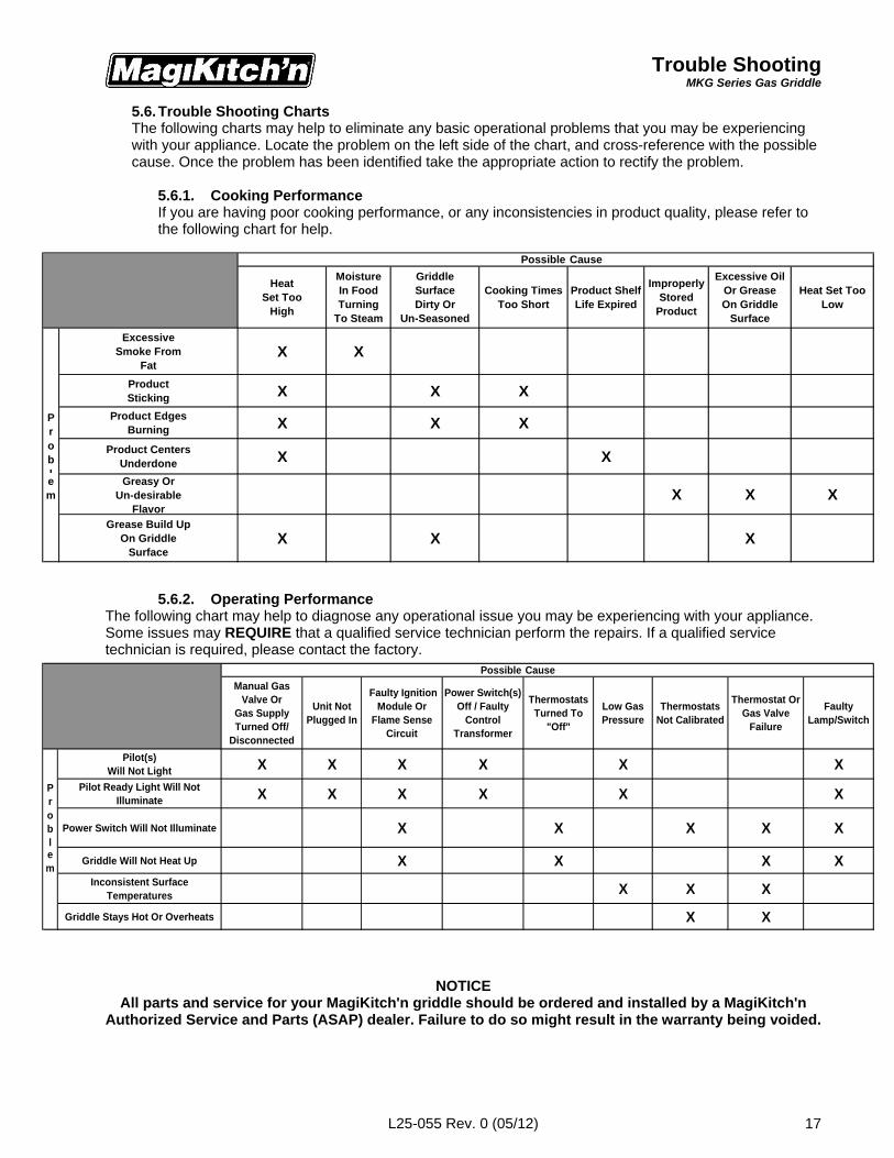
5.6. Trouble Shooting ChartsThe following charts may help to eliminate any basic operational problems that you may be experiencingwith your appliance. Locate the problem on the left side of the chart, and cross-reference with the possiblecause. Once the problem has been identified take the appropriate action to rectify the problem.
5.6.1. Cooking PerformanceIf you are having poor cooking performance, or any inconsistencies in product quality, please refer tothe following chart for help.
5.6.2. Operating PerformanceThe following chart may help to diagnose any operational issue you may be experiencing with your appliance.Some issues may REQUIRE that a qualified service technician perform the repairs. If a qualified servicetechnician is required, please contact the factory.
NOTICEAll parts and service for your MagiKitch'n griddle should be ordered and installed by a MagiKitch'n
Authorized Service and Parts (ASAP) dealer. Failure to do so might result in the warranty being voided.
AccessoriesMKG Series Gas Griddle
L25-055 Rev. 0 (05/12)18
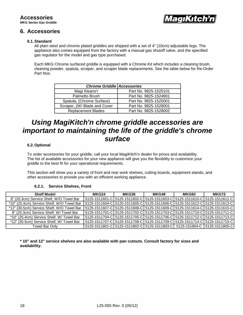
Shelf Model MKG24 MKG36 MKG48 MKG60 MKG728" (20.3cm) Service Shelf, W/O Towel Bar 5125-1511601-C 5125-1511602-C 5125-1511603-C 5125-1511610-C 5125-1511611-C
*10" (25.4cm) Service Shelf, W/O Towel Bar 5125-1511604-C 5125-1511605-C 5125-1511606-C 5125-1511612-C 5125-1511613-C*12" (30.5cm) Service Shelf, W/O Towel Bar 5125-1511607-C 5125-1511608-C 5125-1511609-C 5125-1511614-C 5125-1511615-C
8" (20.3cm) Service Shelf, W/ Towel Bar 5125-1511701-C 5125-1511702-C 5125-1511703-C 5125-1511710-C 5125-1511711-C*10" (25.4cm) Service Shelf, W/ Towel Bar 5125-1511704-C 5125-1511705-C 5125-1511706-C 5125-1511712-C 5125-1511713-C*12" (30.5cm) Service Shelf, W/ Towel Bar 5125-1511707-C 5125-1511708-C 5125-1511709-C 5125-1511714-C 5125-1511715-C
Towel Bar Only 5125-1511801-C 5125-1511802-C 5125-1511803-C 5125-151804-C 5125-1511805-C
6. Accessories
6.1. StandardAll plain steel and chrome plated griddles are shipped with a set of 4” (10cm) adjustable legs. Theappliance also comes equipped from the factory with a manual gas shutoff valve, and the specifiedgas regulator for the model and gas type purchased.
Each MKG Chrome surfaced griddle is equipped with a Chrome Kit which includes a cleaning brush,cleaning powder, spatula, scraper, and scraper blade replacements. See the table below for Re-OrderPart Nos.
Using MagiKitch'n chrome griddle accessories areimportant to maintaining the life of the griddle's chrome
surface6.2. Optional
To order accessories for your griddle, call your local MagiKitch’n dealer for prices and availability.The list of available accessories for your new appliance will give you the flexibility to customize yourgriddle to the best fit for your operational requirements.
This section will show you a variety of front and rear work shelves, cutting boards, equipment stands, andother accessories to provide you with an efficient working appliance.
6.2.1. Service Shelves, Front
* 10” and 12” service shelves are also available with pan cutouts. Consult factory for sizes andavailability.
Chrome Griddle AccessoriesMagi Kleans'r Part No. 9825-1525101
Palmetto Brush Part No. 9825-1524901Spatula, (Chrome Surface) Part No. 9825-1525001
Scraper, (W/ Blade and Cover Part No. 9825-1528001Replacement Blades Part No. 9825-1528002
AccessoriesMKG Series Gas Griddle
L25-055 Rev. 0 (05/12) 19
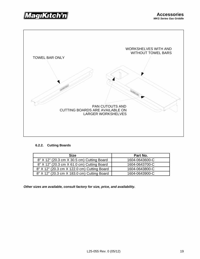
TOWEL BAR ONLY
CUTTING BOARDS ARE AVAILABLE ONLARGER WORKSHELVES
WORKSHELVES WITH ANDWITHOUT TOWEL BARS
PAN CUTOUTS AND
Size Part No.8" X 12" (20.3 cm X 30.5 cm) Cutting Board 1604-0643600-C8" X 12" (20.3 cm X 61.0 cm) Cutting Board 1604-0643700-C8" X 12" (20.3 cm X 122.0 cm) Cutting Board 1604-0643800-C8" X 12" (20.3 cm X 183.0 cm) Cutting Board 1604-0643900-C
6.2.2. Cutting Boards
Other sizes are available, consult factory for size, price, and availability.
AccessoriesMKG Series Gas Griddle
L25-055 Rev. 0 (05/12)20
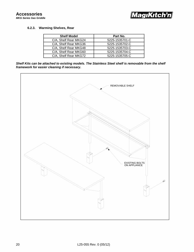
6.2.3. Warming Shelves, Rear
Shelf Kits can be attached to existing models. The Stainless Steel shelf is removable from the shelfframework for easier cleaning if necessary.
Shelf Model Part No.C/A, Shelf Rear MKG24 5225-1535701-CC/A, Shelf Rear MKG36 5225-1535702-CC/A, Shelf Rear MKG48 5225-1535703-CC/A, Shelf Rear MKG60 5225-1535704-CC/A, Shelf Rear MKG72 5225-1535705-C
EXISTING BOLTSON APPLIANCE
REMOVABLE SHELF

AccessoriesMKG Series Gas Griddle
L25-055 Rev. 0 (05/12) 21
vvvv
6.2.4. Equipment Stands
Equipment stands can be ordered with legs or casters (stands with casters shipped after May 2006 areequipped with adjustable casters).
NOTE:It should also be noted that when ordering an equipment stand for your MKG appliance, you will also
need to order and MKG Joining Kit, Part No. 7225-1512101.
Equipment stands may be used to hold multiple MKG Griddles. They are also compatible withMagiKitch’n Series 600 APM Charbroilers.
Equipment Stand Model Part No.MKG24, W/ Legs 5225-1512001-C
MKG24, W/ Casters 5225-1512002-CMKG36, W/ Legs 5225-1512005-C
MKG36, W/ Casters 5225-1512006-CMKG48, W/ Legs 5225-1512007-C
MKG48, W/ Casters 5225-1512008-CMKG60, W/ Legs 5225-1512009-C
MKG60, W/ Casters 5225-1512010-CMKG72, W/ Legs 5225-1512011-C
MKG72, W/ Casters 5225-1512012-C
AccessoriesMKG Series Gas Griddle
L25-055 Rev. 0 (05/12)22
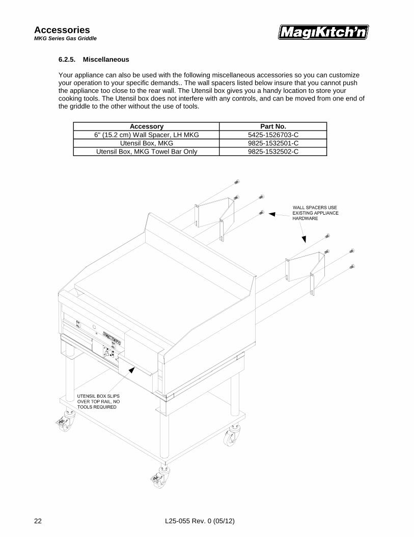
6.2.5. Miscellaneous
Your appliance can also be used with the following miscellaneous accessories so you can customizeyour operation to your specific demands.. The wall spacers listed below insure that you cannot pushthe appliance too close to the rear wall. The Utensil box gives you a handy location to store yourcooking tools. The Utensil box does not interfere with any controls, and can be moved from one end ofthe griddle to the other without the use of tools.
Accessory Part No.6" (15.2 cm) Wall Spacer, LH MKG 5425-1526703-C
Utensil Box, MKG 9825-1532501-CUtensil Box, MKG Towel Bar Only 9825-1532502-C


L25-055 Rev. 0 (05/12)
In the event of problems with or questionsabout your order, please contact theMagiKitch’n factory at:
PH- (603) 225-6684 World WideWebsite- www.magikitchn.com
In the event of problems with or questionsabout your equipment, please contact theMagiKitch’n Authorized Service and Partsrepresentative (ASAP) covering your area,or contact Pitco at the numbers listed to theleft.
MAILING ADDRESS – P.O. BOX 501, CONCORD, NH 03302-0501SHIPPING ADDRESS – 10 FERRY ST., CONCORD, NH 03301