Embed Size (px)
Citation preview
Minnesota Wing Advanced Aircrew Training
Introduction to G1000 Search Patterns
Introduction and Planning Steps
Introduction
Some G1000 Integrated Flight Decks (none in Minnesota yet) have the capability to program search patterns in a similar fashion as the GX55
The G1000 provides – 10 inch multi-colored moving map– Terrain– Obstructions– Inset map on PFD– Course deviation Indicator (CDI) for search pattern
in an HSI format on the PFD– Coupling to autopilot
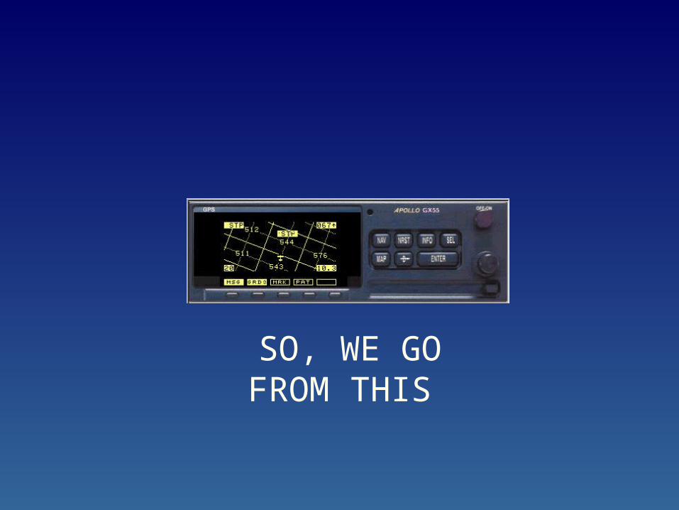
SO, WE GO FROM THIS
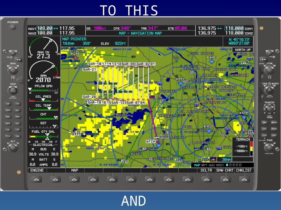
AND
TO THIS
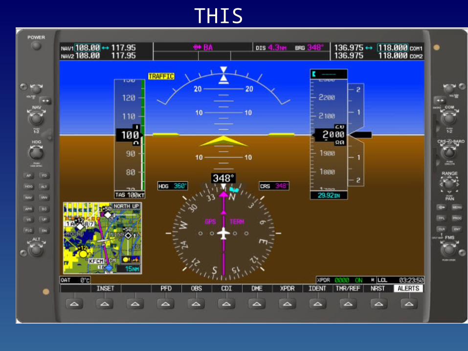
THIS

But….
Although the G1000 will guide the pilot through the search area safely and accurately, it does require more planning and work before programming
Why?
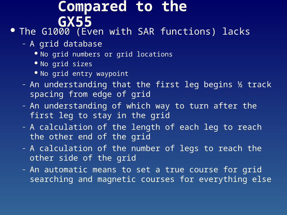
Compared to the GX55 The G1000 (Even with SAR functions) lacks
– A grid database No grid numbers or grid locations No grid sizes No grid entry waypoint
– An understanding that the first leg begins ½ track spacing from edge of grid
– An understanding of which way to turn after the first leg to stay in the grid
– A calculation of the length of each leg to reach the other end of the grid
– A calculation of the number of legs to reach the other side of the grid
– An automatic means to set a true course for grid searching and magnetic courses for everything else
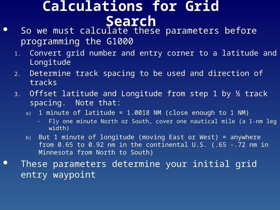
Calculations for Grid Search So we must calculate these parameters before
programming the G1000 1. Convert grid number and entry corner to a latitude and
Longitude
2. Determine track spacing to be used and direction of tracks
3. Offset latitude and Longitude from step 1 by ½ track spacing. Note that:
a) 1 minute of latitude = 1.0018 NM (close enough to 1 NM)– Fly one minute North or South, cover one nautical mile (a 1-nm leg width)
b) But 1 minute of longitude (moving East or West) = anywhere from 0.65 to 0.92 nm in the continental U.S. (.65 -.72 nm in Minnesota from North to South)
These parameters determine your initial grid entry waypoint
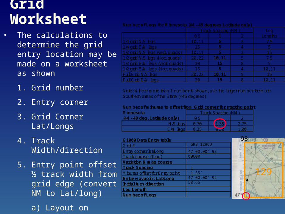
Grid Worksheet Number of Legs for Minnesota (44 - 49 degrees Latitude only)Track Spacing (NM) Leg
0.5 1 2 Lengths1/4 grid N/S legs 10, 11 5 3 7.51/4 grid E/W legs 15 8 4 51/2 grid N/S legs (vert. quads) 10, 11 5 3 151/2 grid N/S legs (Hor. quads) 20, 22 10, 11 5 7.51/2 grid E/W legs (vert. quads) 30 15 8 51/2 grid E/W legs (Hor. quads) 15 8 4 10, 11Full Grid N/S legs 20, 22 10, 11 5 15Full Grid E/W legs 30 15 8 10, 11
Note: Where more than 1 number is shown, use the larger number for more Southern areas of the State (<46 degrees)
Number of minutes to offset from Grid corner for starting pointMinnesota Track Spacing (NM)(44 - 49 deg. Latitude only) 0.5 1 2
N/S legs 0.70 1.35 2.75E/W legs 0.25 0.50 1.00
G1000 Data Entry tableGrid #Entry corner lat/LongTrack course (True)Variation & mag courseTrack SpacingMinutes offset for Entry pointEntry waypoint Lat/LongInitial turn directionLeg LengthNumber of Legs
• The calculations to determine the grid entry location may be made on a worksheet as shown
1. Grid number
2. Entry corner
3. Grid Corner Lat/Longs
4. Track Width/direction
5. Entry point offset ½ track width from grid edge (convert NM to Lat/long)
a) Layout on gridded sectional or
b) use sheet shown
GRB 129CD
47 00.00’ 93 00.00’360
11.35’
47 00.00’ 92 58.65’129
93
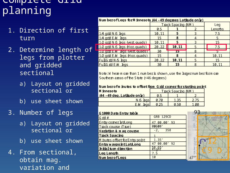
Complete Grid planning
1. Direction of first turn
2. Determine length of legs from plotter and gridded sectional
a) Layout on gridded sectional or
b) use sheet shown
3. Number of legs
a) Layout on gridded sectional or
b) use sheet shown
4. From sectional, obtain mag. variation and convert true course to magnetic course
Number of Legs for Minnesota (44 - 49 degrees Latitude only)Track Spacing (NM) Leg
0.5 1 2 Lengths1/4 grid N/S legs 10, 11 5 3 7.51/4 grid E/W legs 15 8 4 51/2 grid N/S legs (vert. quads) 10, 11 5 3 151/2 grid N/S legs (Hor. quads) 20, 22 10, 11 5 7.51/2 grid E/W legs (vert. quads) 30 15 8 51/2 grid E/W legs (Hor. quads) 15 8 4 10, 11Full Grid N/S legs 20, 22 10, 11 5 15Full Grid E/W legs 30 15 8 10, 11
Note: Where more than 1 number is shown, use the larger number for more Southern areas of the State (<46 degrees)
Number of minutes to offset from Grid corner for starting pointMinnesota Track Spacing (NM)(44 - 49 deg. Latitude only) 0.5 1 2
N/S legs 0.70 1.35 2.75E/W legs 0.25 0.50 1.00
G1000 Data Entry tableGrid #Entry corner lat/LongTrack course (True)Variation & mag courseTrack SpacingMinutes offset for Entry pointEntry waypoint Lat/LongInitial turn directionLeg LengthNumber of Legs
GRB 129CD
47 00.00’ 93 00.00’360-2, 358
11.35’
47 00.00’ 92 58.65’ 129
93
C DRight7.510
Other Search Patterns The G1000 will also perform other searches
– Creeping line Planning and programming similar to (long skinny) grid search
– Triangular sector No converting from grids to miles required in planning Simply determine initial waypoint lat/long, and initial leg length,
direction and turn direction
– Expanding Square Similar to GX55 planning No converting from grids to miles required in planning Simply determine initial waypoint lat/long, and initial leg direction, turn
direction, spacing, and number of legs
– Parallel course route search Programmed outside of search and Rescue menu Program normal flight plan and input offset distance
G1000 Controls (for SAR functions)
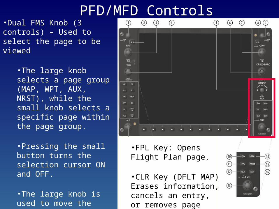
•Dual FMS Knob (3 controls) – Used to select the page to be viewed
•The large knob selects a page group (MAP, WPT, AUX, NRST), while the small knob selects a specific page within the page group.
•Pressing the small button turns the selection cursor ON and OFF.
•The large knob is used to move the cursor on the page, while the small knob is used to select individual characters for the highlighted cursor location.
PFD/MFD Controls
•FPL Key: Opens Flight Plan page.
•CLR Key (DFLT MAP) Erases information, cancels an entry, or removes page menus.
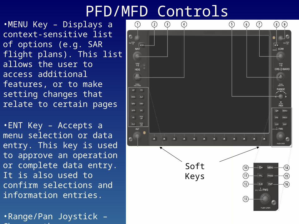
•MENU Key – Displays a context-sensitive list of options (e.g. SAR flight plans). This list allows the user to access additional features, or to make setting changes that relate to certain pages
•ENT Key – Accepts a menu selection or data entry. This key is used to approve an operation or complete data entry. It is also used to confirm selections and information entries.
•Range/Pan Joystick – Changes the map range (distance top to bottom of map display) when rotated. Activates the map pointer when pressed.
PFD/MFD Controls
Soft Keys
G1000 Set-up and Hints
Set-up and Hints
To enable the Search and Rescue functions on the G1000, the software must be recent enough to contain the search pattern features, and
The features must be enabled with a SD unlock card that is inserted into the top SD card slot on the MFD
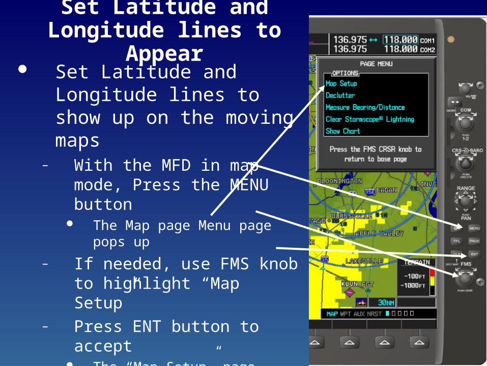
Set Latitude and Longitude lines to Appear
Set Latitude and Longitude lines to show up on the moving maps
– With the MFD in map mode, Press the MENU button
The Map page Menu page pops up
– If needed, use FMS knob to highlight “Map Setup”
– Press ENT button to accept The “Map Setup” page appears
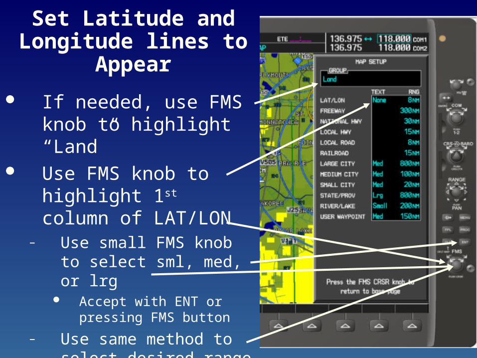
Set Latitude and Longitude lines to
Appear
If needed, use FMS knob to highlight “Land”
Use FMS knob to highlight 1st column of LAT/LON
– Use small FMS knob to select sml, med, or lrg
Accept with ENT or pressing FMS button
– Use same method to select desired range
Press FMS button to exit
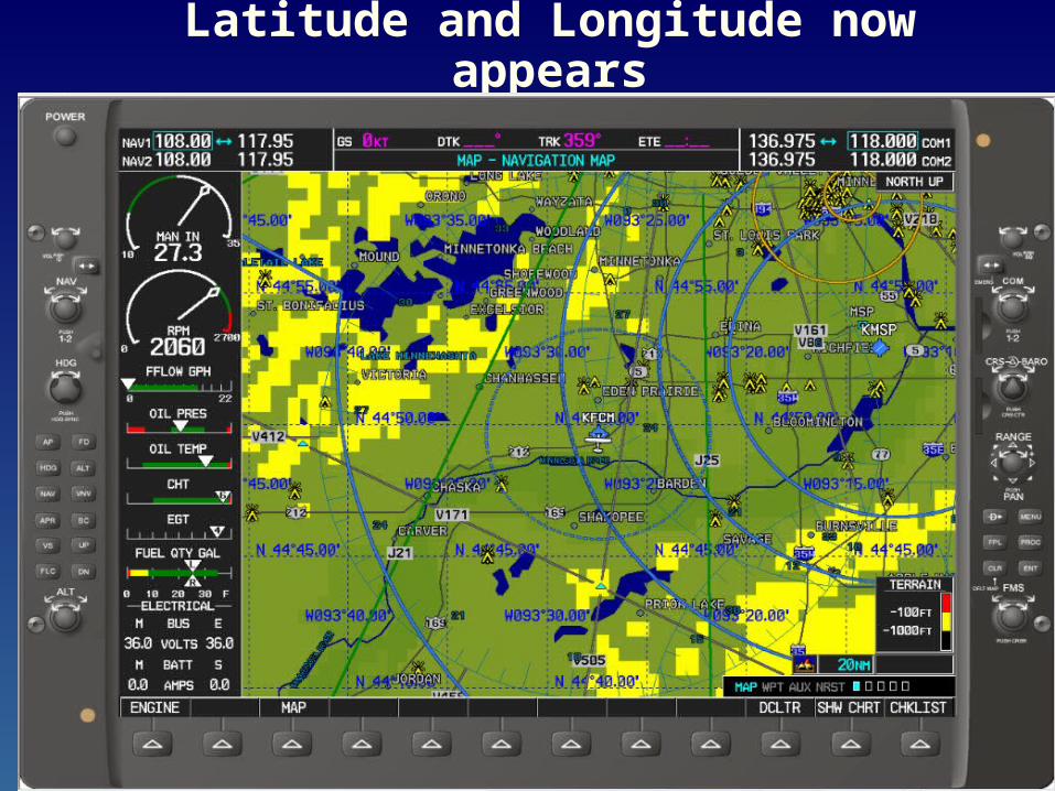
Latitude and Longitude now appears
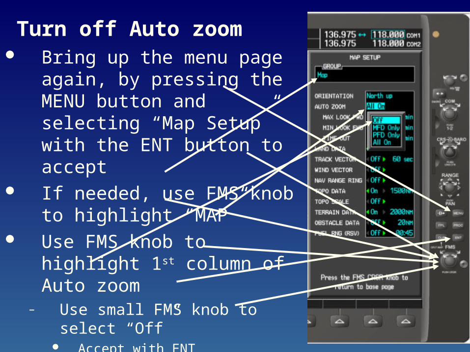
Turn off Auto zoom Bring up the menu page again,
by pressing the MENU button and selecting “Map Setup” with the ENT button to accept
If needed, use FMS knob to highlight “MAP”
Use FMS knob to highlight 1st column of Auto zoom
– Use small FMS knob to select “Off”
Accept with ENT
– Press FMS button to exit
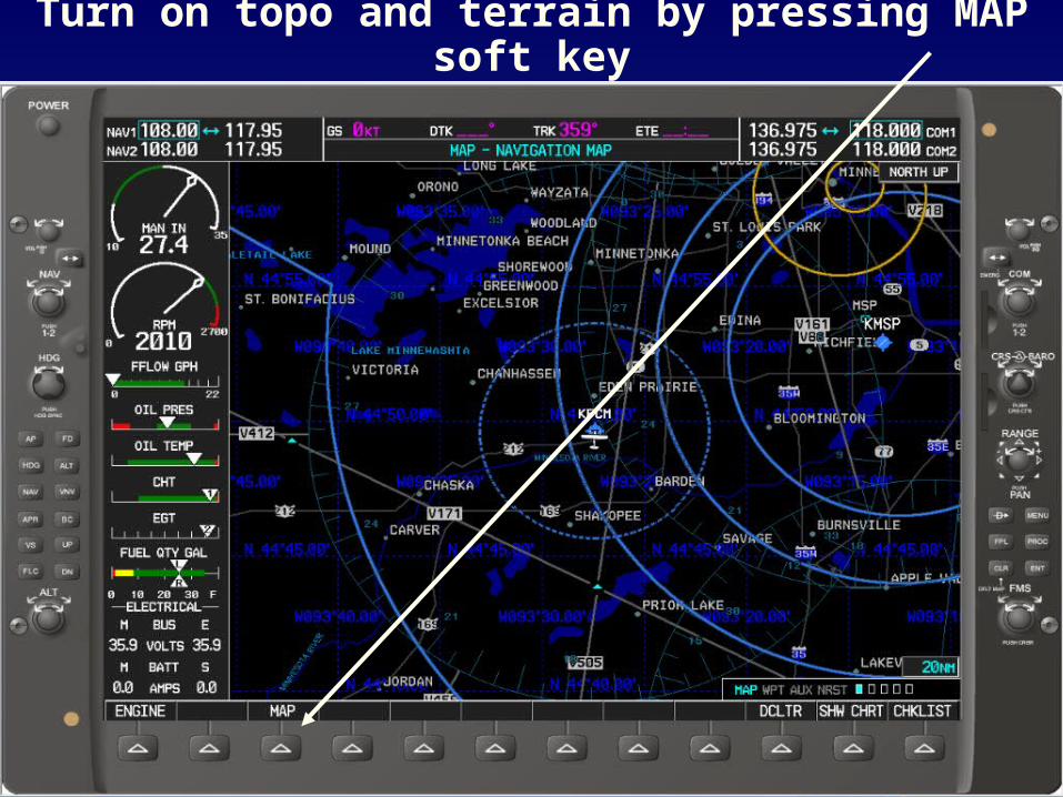
Turn on topo and terrain by pressing MAP soft key
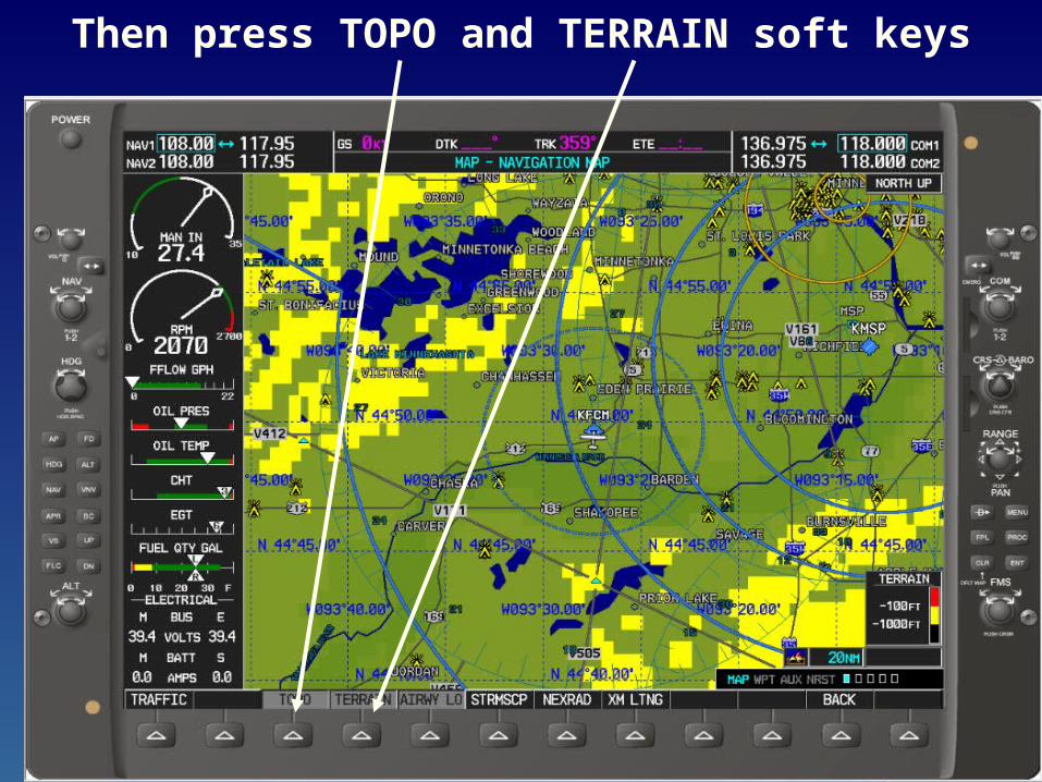
Then press TOPO and TERRAIN soft keys

Create User Defined Waypoint
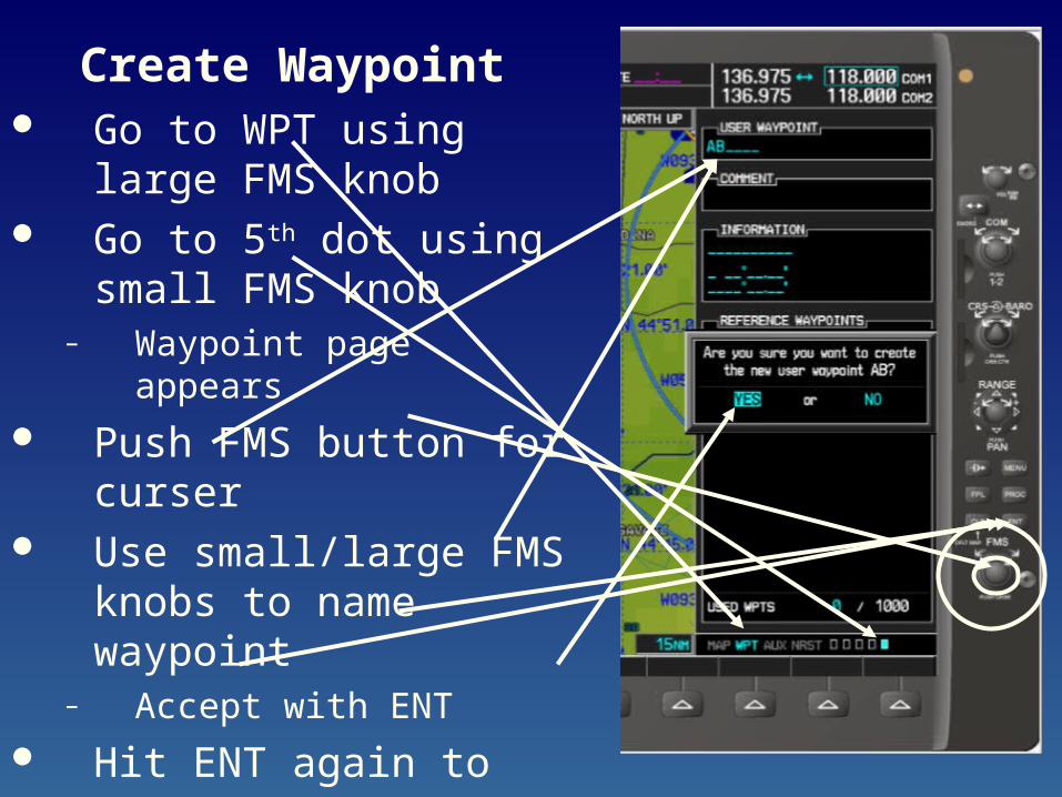
Create Waypoint Go to WPT using large
FMS knob Go to 5th dot using small
FMS knob– Waypoint page appears
Push FMS button for curser
Use small/large FMS knobs to name waypoint
– Accept with ENT
Hit ENT again to say Yes– Jumps you down to ref
section
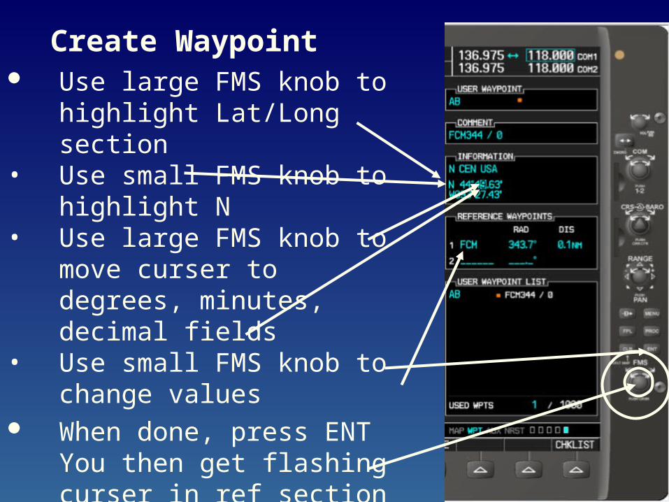
Create Waypoint Use large FMS knob to
highlight Lat/Long section• Use small FMS knob to
highlight N• Use large FMS knob to move
curser to degrees, minutes, decimal fields
• Use small FMS knob to change values
When done, press ENT You then get flashing curser in ref section
Press FMS button to finish
Program SAR Pattern into G1000
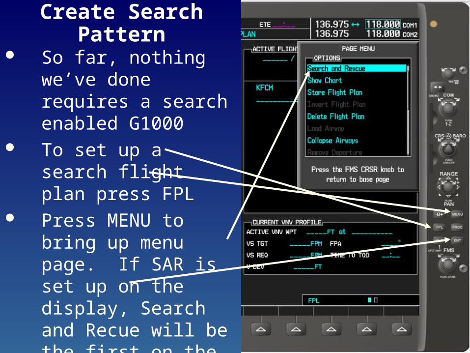
Create Search Pattern
So far, nothing we’ve done requires a search enabled G1000
To set up a search flight plan press FPL
Press MENU to bring up menu page. If SAR is set up on the display, Search and Recue will be the first on the list
Press ENT to select – This Brings up the SAR pattern page
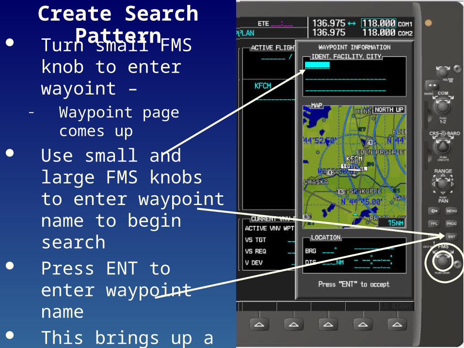
Create Search Pattern Turn small FMS knob to
enter wayoint – – Waypoint page comes up
Use small and large FMS knobs to enter waypoint name to begin search
Press ENT to enter waypoint name
This brings up a waypoint page. Press ENT to accept
– Brings up SAR page again
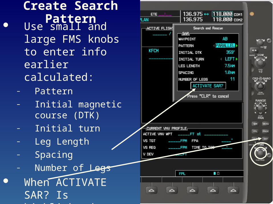
Create Search Pattern Use small and large
FMS knobs to enter info earlier calculated:
– Pattern– Initial magnetic course
(DTK)– Initial turn– Leg Length– Spacing– Number of Legs
When ACTIVATE SAR? Is highlighted, press ENT– flight plan is now activated
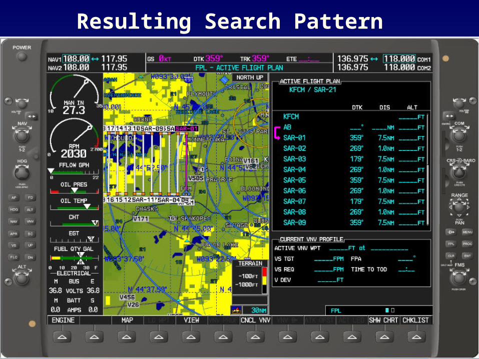
Resulting Search Pattern
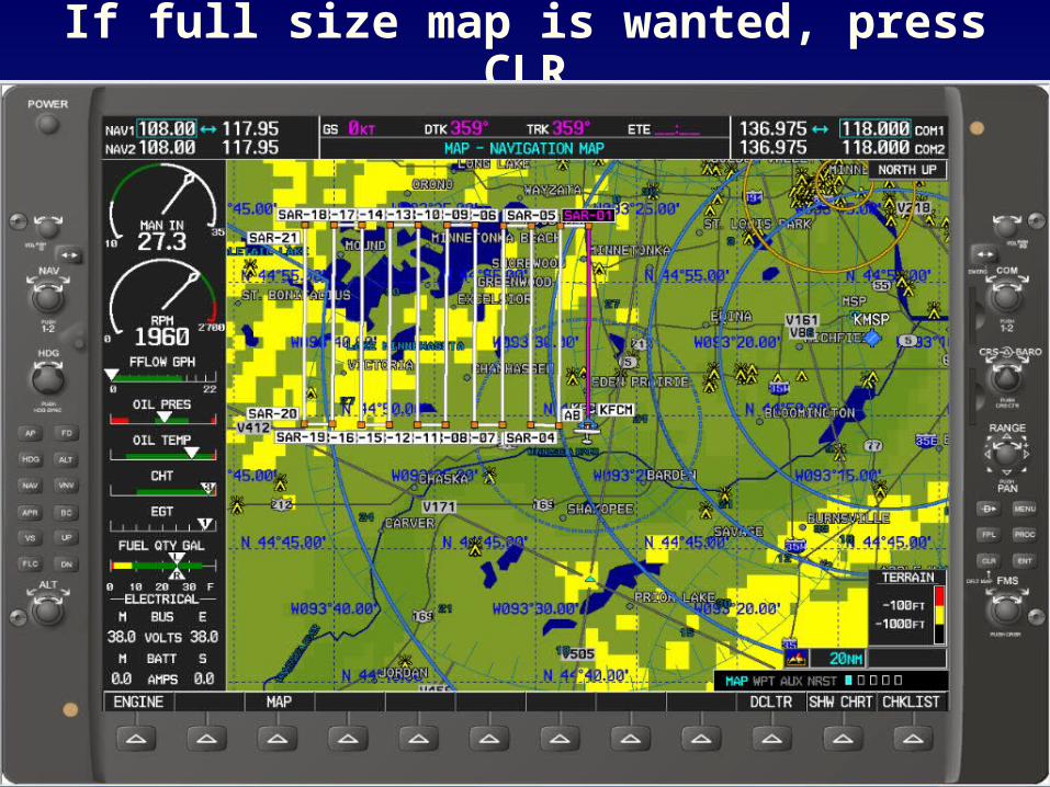
If full size map is wanted, press CLR
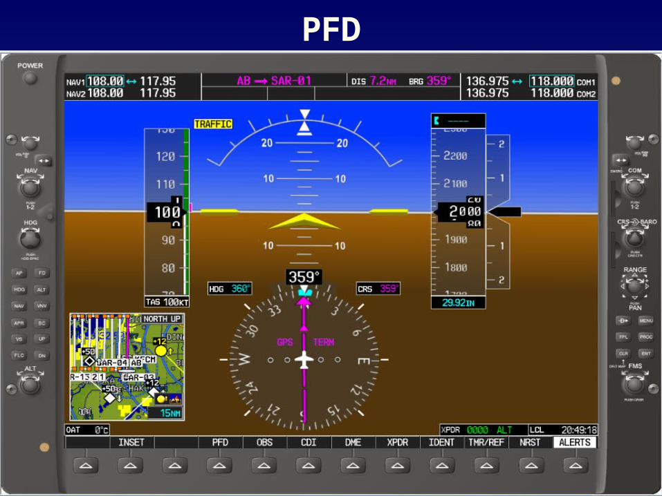
PFD
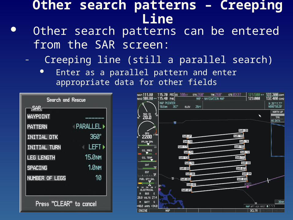
Other search patterns – Creeping Line Other search patterns can be entered from the
SAR screen:– Creeping line (still a parallel search)
Enter as a parallel pattern and enter appropriate data for other fields
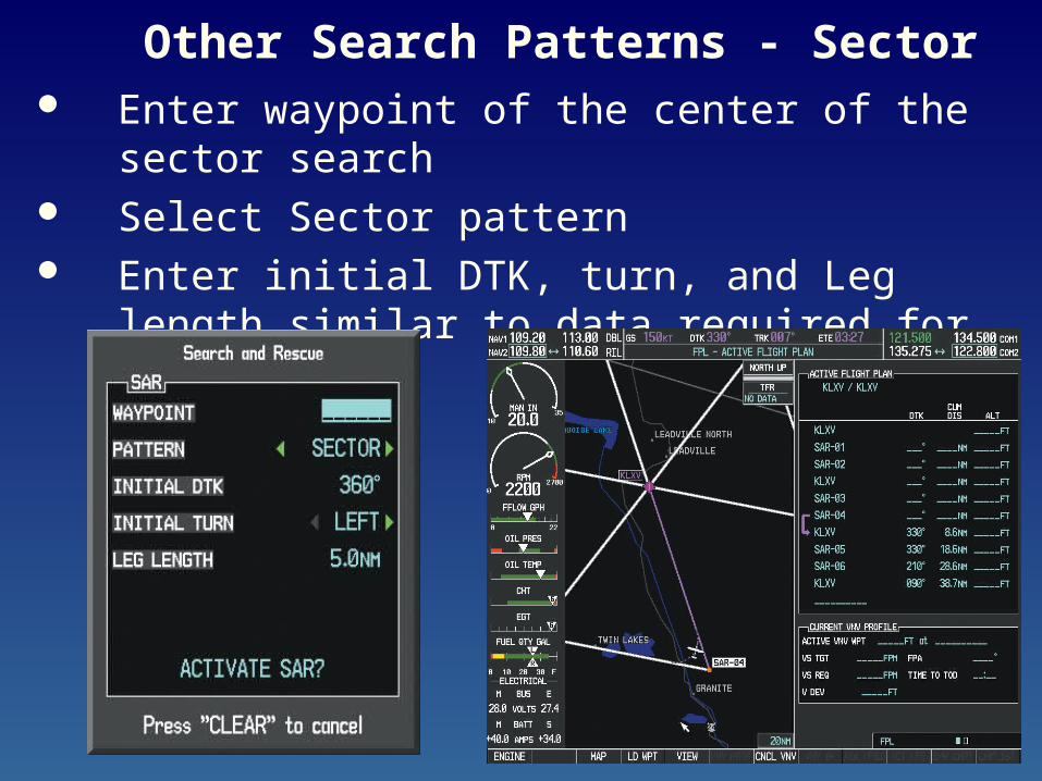
Other Search Patterns - Sector Enter waypoint of the center of the sector search Select Sector pattern Enter initial DTK, turn, and Leg length similar to
data required for GX-55
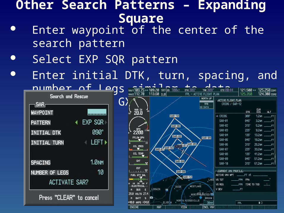
Other Search Patterns – Expanding Square Enter waypoint of the center of the search pattern Select EXP SQR pattern Enter initial DTK, turn, spacing, and number of
Legs similar to data required for GX-55
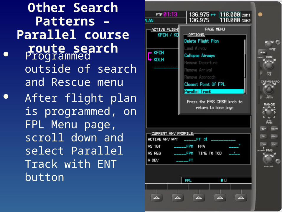
Other Search Patterns – Parallel course route
search Programmed outside of
search and Rescue menu
After flight plan is programmed, on FPL Menu page, scroll down and select Parallel Track with ENT button
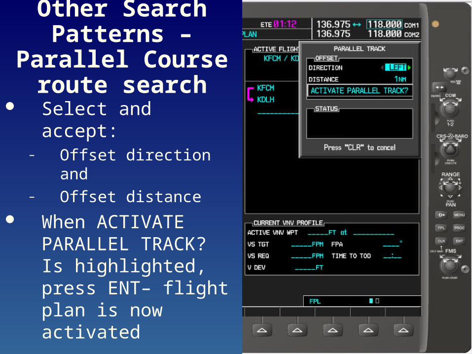
Other Search Patterns – Parallel
Course route search Select and accept:
– Offset direction and – Offset distance
When ACTIVATE PARALLEL TRACK? Is highlighted, press ENT– flight plan is now activated
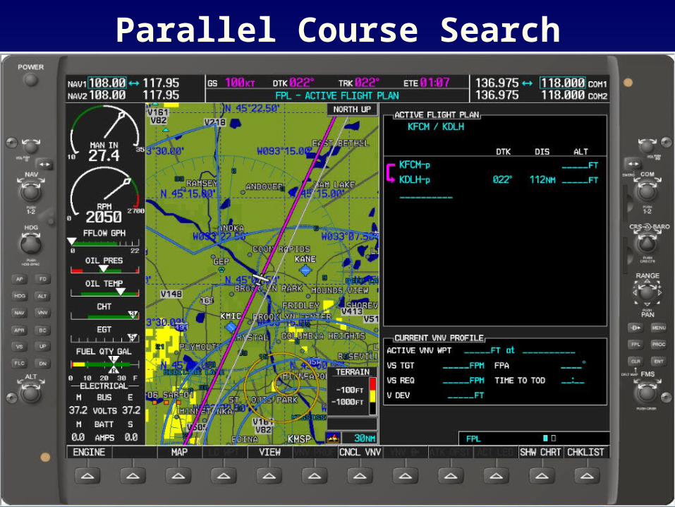
Parallel Course Search
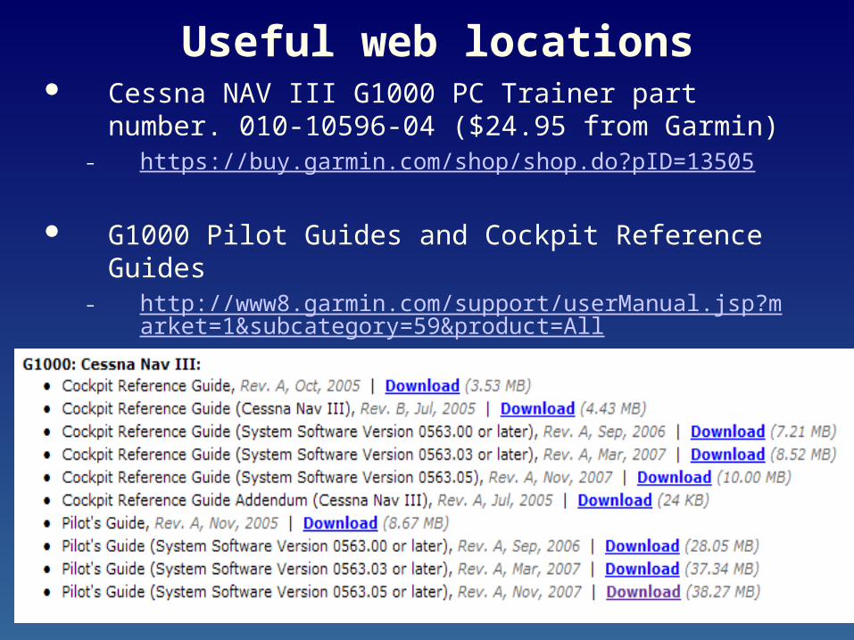
Useful web locations Cessna NAV III G1000 PC Trainer part number. 010-
10596-04 ($24.95 from Garmin)– https://buy.garmin.com/shop/shop.do?pID=13505
G1000 Pilot Guides and Cockpit Reference Guides– http://www8.garmin.com/support/userManual.jsp?market=1&s
ubcategory=59&product=All
Useful web locations
G1000 Search and Rescue Pilot’s Guide– http://www.mncap.org/es/reference_aircrew.cfm
This Presentation– http://www.mncap.org/es/reference_aircrew.cfm