Embed Size (px)
Citation preview
8/3/2019 Minimax Diagrams
http://slidepdf.com/reader/full/minimax-diagrams 1/10
MiniMax
Diagrams and Table Page 1 of 3
1.8m x 0.7m
3.7 m
Safe Working Height 2.60m
Platform Height 0.60m
Base Pack
Safe Working Height 3.70m
Platform Height 1.70m
Base Pack + Guardrails + 2 x Small Stabiliser Packs
2.6 m
MiniMax Pack Details
8/3/2019 Minimax Diagrams
http://slidepdf.com/reader/full/minimax-diagrams 2/10
MiniMax
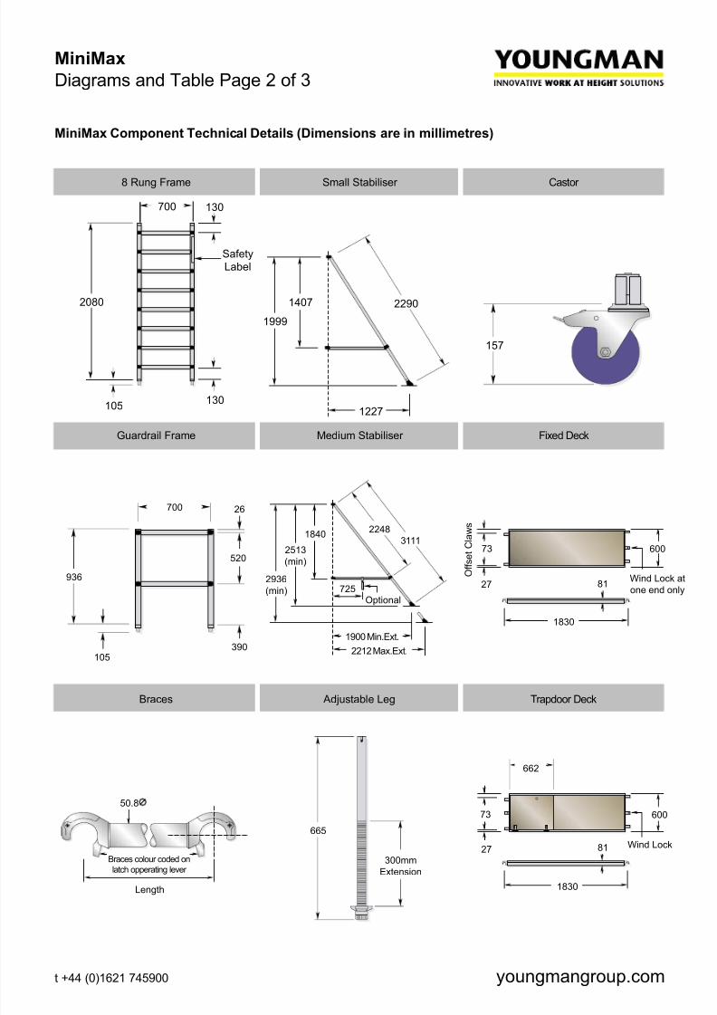
Diagrams and Table Page 2 of 3
MiniMax Component Technical Details (Dimensions are in millimetres)
130
130700
2080
105130
SafetyLabel
8 Rung Frame Small Stabiliser Castor
1227
22901407
1999
157
Guardrail Frame Medium Stabiliser Fixed Deck
8/3/2019 Minimax Diagrams
http://slidepdf.com/reader/full/minimax-diagrams 3/10
MiniMax
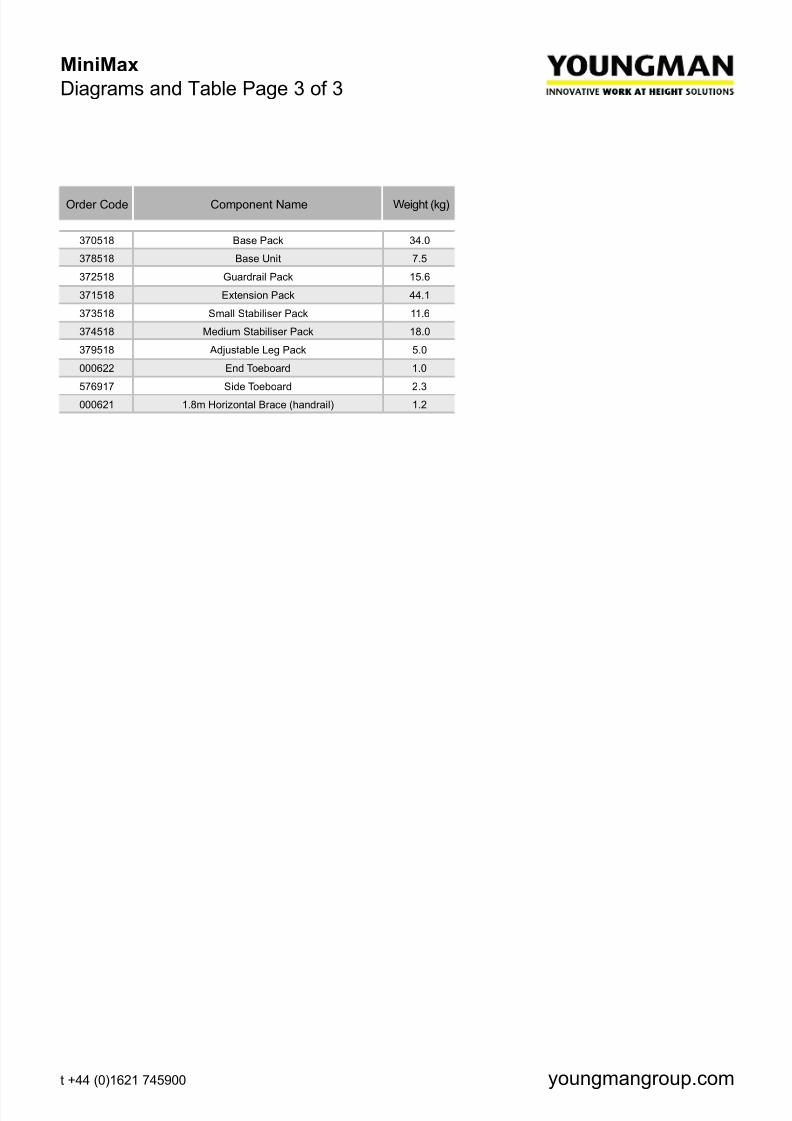
Diagrams and Table Page 3 of 3
Order Code Component Name Weight (kg)
370518 Base Pack 34.0
378518 Base Unit 7.5
372518 Guardrail Pack 15.6
371518 Extension Pack 44.1
373518 Small Stabiliser Pack 11.6
374518 Medium Stabiliser Pack 18.0
379518 Adjustable Leg Pack 5.0
000622 End Toeboard 1.0
576917 Side Toeboard 2.3
000621 1.8m Horizontal Brace (handrail) 1.2
8/3/2019 Minimax Diagrams
http://slidepdf.com/reader/full/minimax-diagrams 4/10
MiniMax
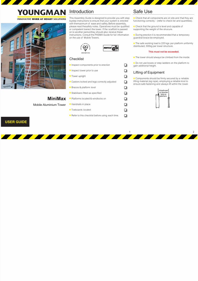
Mobile Aluminium Tower
USER GUIDE
Introduction Safe Use
This Assembly Guide is designed to provide you with step
bystep instructions to ensure that your system is erected
with themaximum of ease and safety. Before assembly,
please read thesafety notes. Operatives must be qualified
or competent toerect the tower. If the scaffold is passed
on to another personthey should also receive these
instructions. Consult the PASMA Guide for full informationon the use of Mobile Towers.
Checklist
Inspect components prior to erection
Inspect tower prior to use
Tower upright
Castors locked and legs correctly adjusted
Braces & platform level
Stabilisers fitted as specified
Platforms located & windlocks on
Handrails in place
Toeboards located
Refer to this checklist before using each time.
Check that all components are on site and that they are
functioning correctly – (refer to check list and quantities).
Check that the ground is level and capable of
supporting the weight of the strucure.
During erection it is recommended that a temporaryguardrail brace be employed.
The safe working load is 220 kgs per platform uniformly
distributed, 500kg per tower structure.
This must not be exceeded.
The tower should always be climbed from the inside.
Do not use boxes or step ladders on the platform to
gain additional height.
Lifting of Equipment
Components should be firmly secured by a reliable
lifting material (eg rope), employing a reliable knot to
ensure safe fastening and always lift within the tower.
1 2
8/3/2019 Minimax Diagrams
http://slidepdf.com/reader/full/minimax-diagrams 5/10
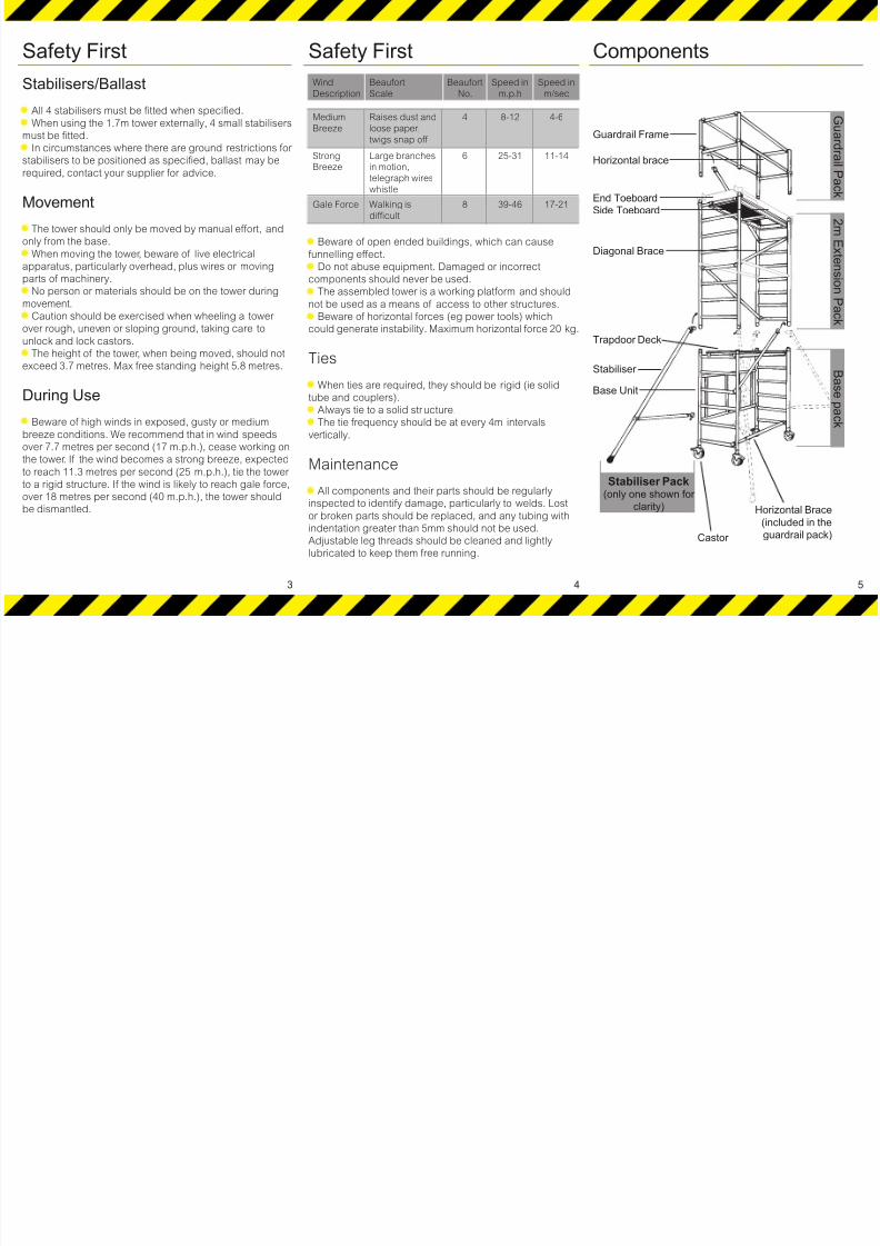
Safety First
Stabilisers/Ballast
All 4 stabilisers must be fitted when specified.
When using the 1.7m tower externally, 4 small stabilisers
must be fitted.
In circumstances where there are ground restrictions for
stabilisers to be positioned as specified, ballast may be
required, contact your supplier for advice.
Movement
The tower should only be moved by manual effort, and
only from the base.
When moving the tower, beware of live electrical
apparatus, particularly overhead, plus wires or moving
parts of machinery.
No person or materials should be on the tower during
movement.Caution should be exercised when wheeling a tower
over rough, uneven or sloping ground, taking care to
unlock and lock castors.
The height of the tower, when being moved, should not
exceed 3.7 metres. Max free standing height 5.8 metres.
During Use
Beware of high winds in exposed, gusty or medium
breeze conditions. We recommend that in wind speeds
over 7.7 metres per second (17 m.p.h.), cease working on
the tower. If the wind becomes a strong breeze, expectedto reach 11.3 metres per second (25 m.p.h.), tie the tower
to a rigid structure. If the wind is likely to reach gale force,
over 18 metres per second (40 m.p.h.), the tower should
be dismantled.
Safety First
Wind
Description
Beaufort
Scale
Beaufort
No.
Speed in
m.p.h
Speed in
m/sec
Medium
Breeze
Raises dust and
loose paper,
twigs snap off
4 8-12 4-6
StrongBreeze
Large branchesin motion,
telegraph wires
whistle
6 25-31 11-14
Gale Force Walking is
difficult
8 39-46 17-21
Beware of open ended buildings, which can cause
funnelling effect.
Do not abuse equipment. Damaged or incorrect
components should never be used.
The assembled tower is a working platform and should
not be used as a means of access to other structures.Beware of horizontal forces (eg power tools) which
could generate instability. Maximum horizontal force 20 kg.
Ties
When ties are required, they should be rigid (ie solid
tube and couplers).
Always tie to a solid structure.
The tie frequency should be at every 4m intervals
vertically.
Maintenance
All components and their parts should be regularly
inspected to identify damage, particularly to welds. Lost
or broken parts should be replaced, and any tubing with
indentation greater than 5mm should not be used.
Adjustable leg threads should be cleaned and lightly
lubricated to keep them free running.
3 4
Components
5
Horizontal Brace
(included in the
guardrail pack)Castor
Stabiliser Pack(only one shown for
clarity)
Base Unit
Stabiliser
Diagonal Brace
End ToeboardSide Toeboard
Horizontal brace
Guardrail Frame
G u ar d r ai l P a c k
2 m E x t en s i on
P a c k
B a s e p a c k
Trapdoor Deck
8/3/2019 Minimax Diagrams
http://slidepdf.com/reader/full/minimax-diagrams 6/10
Correctw ay to climbonto
platform
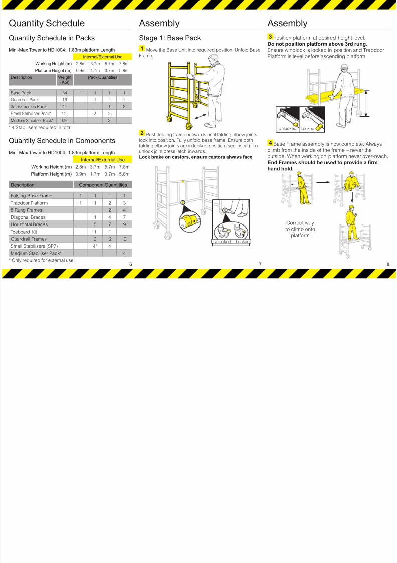
Assembly
Stage 1: Base Pack
Move the Base Unit into required position. Unfold Base
Frame.
Push folding frame outwards until folding elbow joints
lock into position. Fully unfold base frame. Ensure bothfolding elbow joints are in locked position (see inser t). To
unlock joint press latch inwards.
Lock brake on castors, ensure castors always face
Quantity Schedule
Quantity Schedule in Packs
Mini-Max Tower to HD1004: 1.83m platform Length
Internal/External Use
Working Height (m) 2.8m 3.7m 5.7m 7.8m
Platform Height (m) 0.9m 1.7m 3.7m 5.8m
Description Weight
(KG)
Pack Quantities
Base Pack 34 1 1 1 1
Guardrail Pack 16 1 1 1
2m Extension Pack 44 1 2
Small Stabiliser Pack* 12 2 2
Medium Stabiliser Pack* 09 2
* 4 Stabilisers required in total.
Quantity Schedule in Components
Mini-Max Tower to HD1004: 1.83m platform Length
Internal/External Use
Working Height (m) 2.8m 3.7m 5.7m 7.8m
Platform Height (m) 0.9m 1.7m 3.7m 5.8m
Description Component Quantitiies
Folding Base Frame 1 1 1 1
Trapdoor Platform 1 1 2 3
8 Rung Frames 2 4
Diagonal Braces 1 4 7
Horizontal Braces 5 7 9
Toeboard Kit 1 1
Guardrail Frames 2 2 2
Small Stabilisers (SP7) 4* 4
Medium Stabiliser Pack* 4
* Only required for external use.
Assembly
3 Position platform at desired height level.
Do not position platform above 3rd rung.
Ensure windlock is locked in position and Trapdoor
Platform is level before ascending platform.
4 Base Frame assembly is now complete. Always
climb from the inside of the frame – never the
outside. When working on platform never over-reach.
End Frames should be used to provide a firm
hand hold.
6
1
2UN LOCKED LOCK ED
7
Unlocked Locked
Unlocked Locked
Correct way
to climb onto
platform
8
8/3/2019 Minimax Diagrams
http://slidepdf.com/reader/full/minimax-diagrams 7/10
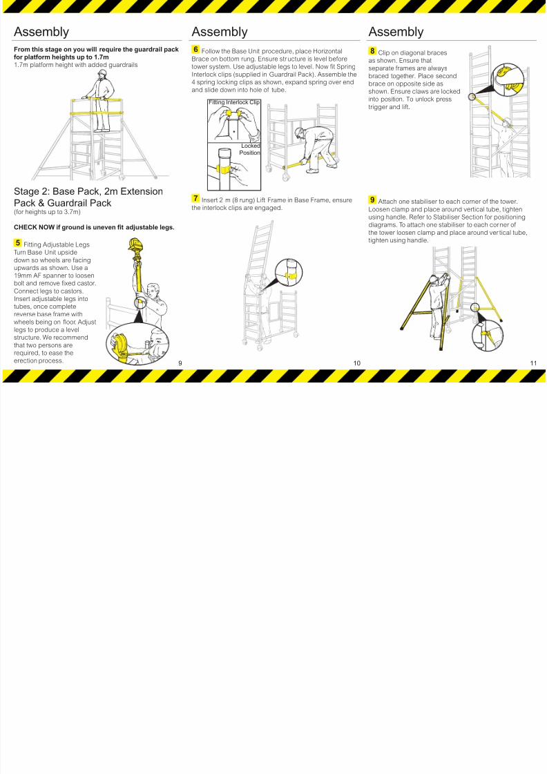
Assembly
From this stage on you will require the guardrail pack
for platform heights up to 1.7m1.7m platform height with added guardrails
Stage 2: Base Pack, 2m ExtensionPack & Guardrail Pack
(for heights up to 3.7m)
CHECK NOW if ground is uneven fit adjustable legs.
5 Fitting Adjustable Legs
Turn Base Unit upside
down so wheels are facing
upwards as shown. Use a
19mm AF spanner to loosen
bolt and remove fixed castor.Connect legs to castors.
Insert adjustable legs into
tubes, once complete
reverse base frame with
wheels being on floor. Adjust
legs to produce a level
structure. We recommend
that two persons are
required, to ease the
erection process.
Assembly
6 Follow the Base Unit procedure, place Horizontal
Brace on bottom rung. Ensure structure is level before
tower system. Use adjustable legs to level. Now fit Spring
Interlock clips (supplied in Guardrail Pack). Assemble the
4 spring locking clips as shown, expand spring over end
and slide down into hole of tube.
7 Insert 2 m (8 rung) Lift Frame in Base Frame, ensure
the interlock clips are engaged.
9
Fitting Interlock Clip
Locked
Position
10
Assembly
8 Clip on diagonal braces
as shown. Ensure that
separate frames are always
braced together. Place second
brace on opposite side as
shown. Ensure claws are locked
into position. To unlock press
trigger and lift.
9 Attach one stabiliser to each corner of the tower.
Loosen clamp and place around vertical tube, tighten
using handle. Refer to Stabiliser Section for positioning
diagrams. To attach one stabiliser to each corner of
the tower loosen clamp and place around ver tical tube,
tighten using handle.
11
8/3/2019 Minimax Diagrams
http://slidepdf.com/reader/full/minimax-diagrams 8/10
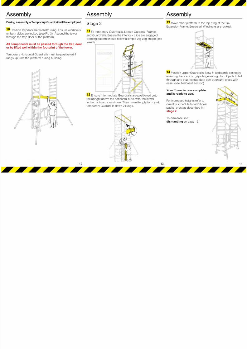
Assembly
During assembly a Temporary Guardrail will be employed.
10 Position Trapdoor Deck on 8th rung. Ensure windlocks
on both sides are locked (see Fig 3). Ascend the tower
through the trap door of the platform.
All components must be passed through the trap door or be lifted well within the footprint of the tower.
Temporary Horizontal Guardrails must be positioned 4
rungs up from the platform during building.
Assembly
Stage 3
11 Fit temporary Guardrails. Locate Guardrail Frames
and Guardrails. Ensure the interlock clips are engaged.
Bracing pattern should follow a simple zig-zag shape (see
insert).
12 Ensure Intermediate Guardrails are positioned onto
the upright above the horizontal tube, with the claws
locked outwards as shown. Then move the platform and
temporary Guardrails down 2 rungs.
12 13
Assembly
13 Move other platform to the top rung of the 2m
Extension Frame. Ensure all Windlocks are locked.
14 Position upper Guardrails. Now fit toeboards cor rectly,
ensuring there are no gaps large enough for objects to fall
through and that the trap door can open and close with
ease. (see Toeboard section).
Your Tower is now complete
and is ready to use.
For increased heights refer to
quantity schedule for additional
packs, erect as described in
stage 2.
To dismantle see
dismantling on page 16.
14
8/3/2019 Minimax Diagrams
http://slidepdf.com/reader/full/minimax-diagrams 9/10
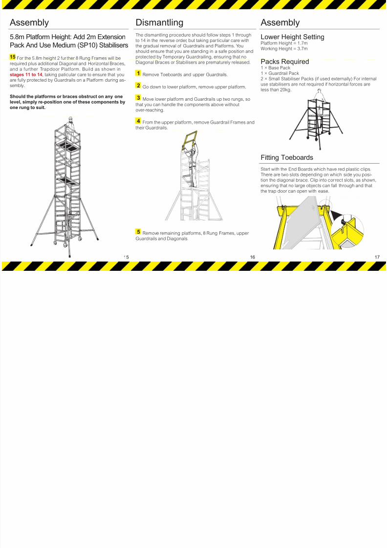
Assembly
5.8m Platform Height: Add 2m Extension
Pack And Use Medium (SP10) Stabilisers
15 For the 5.8m height 2 fur ther 8 Rung Frames will be
required plus additional Diagonal and Horizontal Braces,
and a further Trapdoor Platform. Build as shown instages 11 to 14, taking paticular care to ensure that you
are fully protected by Guardrails on a Platform during as-
sembly.
Should the platforms or braces obstruct on any one
level, simply re-position one of these components by
one rung to suit.
Dismantling
The dismantling procedure should follow steps 1 through
to 14 in the reverse order, but taking par ticular care with
the gradual removal of Guardrails and Platforms. You
should ensure that you are standing in a safe position and
protected by Temporary Guardrailing, ensuring that no
Diagonal Braces or Stabilisers are prematurely released.
1 Remove Toeboards and upper Guardrails.
2 Go down to lower platform, remove upper platform.
3 Move lower platform and Guardrails up two rungs, so
that you can handle the components above without
over-reaching.
4 From the upper platform, remove Guardrail Frames and
their Guardrails.
5 Remove remaining platforms, 8 Rung Frames, upper
Guardrails and Diagonals.
15 16
Assembly
Lower Height SettingPlatform Height = 1.7m
Working Height = 3.7m
Packs Required1 × Base Pack1 × Guardrail Pack
2 × Small Stabiliser Packs (if used externally) For internal
use stabilisers are not required if horizontal forces are
less than 20kg.
Fitting Toeboards
Start with the End Boards which have red plastic clips.
There are two slots depending on which side you posi-
tion the diagonal brace. Clip into correct slots, as shown,
ensuring that no large objects can fall through and that
the trap door can open with ease.
17
8/3/2019 Minimax Diagrams
http://slidepdf.com/reader/full/minimax-diagrams 10/10
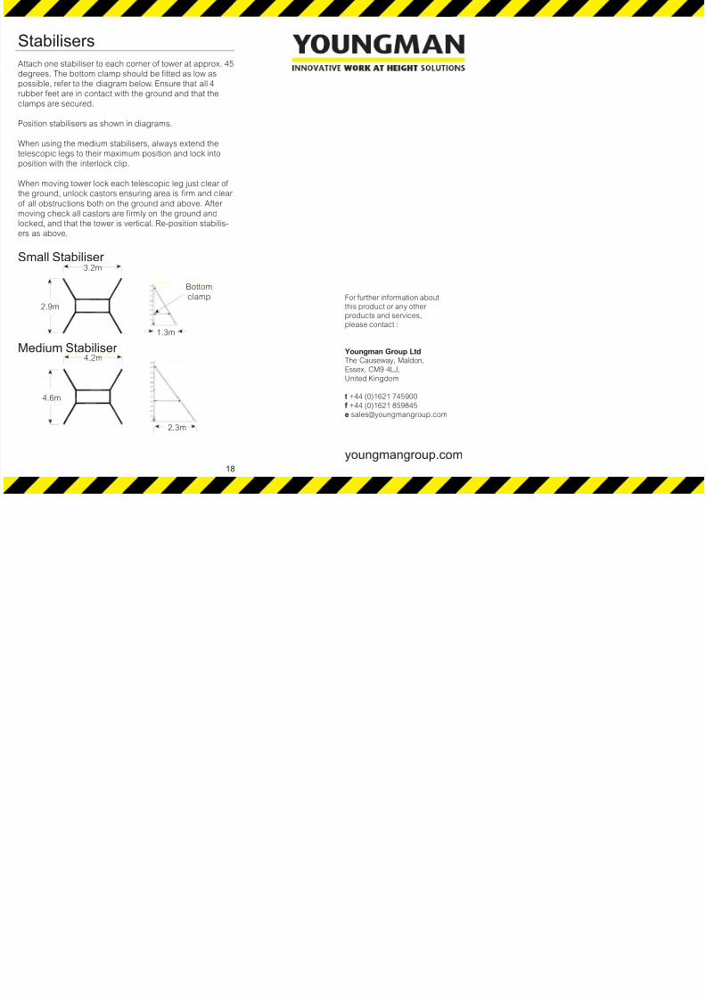
Stabilisers
Attach one stabiliser to each corner of tower at approx. 45
degrees. The bottom clamp should be fitted as low as
possible, refer to the diagram below. Ensure that all 4
rubber feet are in contact with the ground and that the
clamps are secured.
Position stabilisers as shown in diagrams.
When using the medium stabilisers, always extend the
telescopic legs to their maximum position and lock into
position with the interlock clip.
When moving tower lock each telescopic leg just clear of
the ground, unlock castors ensuring area is firm and clear
of all obstructions both on the ground and above. After
moving check all castors are firmly on the ground and
locked, and that the tower is vertical. Re-position stabilis-
ers as above.
Small Stabiliser
Medium Stabiliser
18
2.3m
4.6m
4.2m
2.9m
3.2m
1.3m
Bottom
clamp For further information about
this product or any other
products and services,
please contact :
Youngman Group LtdThe Causeway, Maldon,
Essex, CM9 4LJ,United Kingdom
t +44 (0)1621 745900
f +44 (0)1621 859845
youngmangroup.com