Embed Size (px)
DESCRIPTION
US Goverment Mil standard for the M-1 Helmet as used by parachutiss.
Citation preview
MIL-H-1998G30 March 1988SUPERSEDINGMIL-H-1988F18 April 1975
MILITARYSPECIFICATION
HELMET, GROUNDTROOPS‘; PARACHUTISTS,STEEL,M-1
This specificationis approvedfor use by all Departmentsand AgenciesOfthe Departmentof Defense.
1. SCOPE
1.1 Scope....,~~s”documentcoverssteelhelmetsidentifiedas M-1, with chinetrap.—
1.2 Classification.The helmetsshallbe of the’followingtypes,asspecified(see6.2).
Type I - Helmet,Type II - Helmet,
groundtroops’, steel,F1-1Parachutists,steelM-1
2. APPLICABLEDOCUMENTS
2.1 Governmentdocuments.
# 2.1.1 Specificat,$ons,standards,and handbooks. The followingspecifications,standards,and handbooksforma part of this specificationtothe extentspecifiedherein. Unlessotherwisespecified,the issuesof thesedocumenteehallbe thoselistedin the issueof the Departmentof DefenseIndexof Specificationsand Standards(DODISS) and supplementthereto, citedin the solicitation.
SPECIFICATIONS
FEDERAL
w-s-766 - SteelPlates,Sheets,and Strip - CorrosionRasisting
Beneficialcomments(recommendations,additions,deletions)andany pertinent data which may be of uee in improving thisdocumentehouldbe addreesedto: 0.S. Rrmy Natick Research,Development,and EngineeringCenter,Natick,MA 01760-5014byusing the Self-addressedStandardizationDocument ImprovementtPropoeal (DD Form 1426) appearingat the end of this documentor by letter.
AMSC NIA FSC 8470
DISTRIBUTIONSTATEMENTA. Approvedfor publicrelease;distributionis unlimited
Source: http://www.assistdocs.com -- Downloaded: 2013-07-11T06:56ZCheck the source to verify that this is the current version before use.
PPP-B,-636 .-‘“”PPP-C-1797 ‘-
;MILITARY
MIL-T-704 -MIL-A-13259 -
?iIL-L-35078 -
MIL+-43841 -MIL-S-43912 -MIL-c-46168 -
STANDARDS
‘FEDERAL’
!?ED-STD-595 -
MILITARY
MIL-STD-105 -
““.HIL-STD-129 -. MILJ3TJjL147 -
.,MIL+STD-414 -
MIL-H-1988G
Boxes, Shipping,FiberboardCushioningMaterial, Resilient,Low Density, ~Unicellular,PolypropyleneFoam
Treatmentand Painti!Iqof Material “Armor, Steel: Sheet, Strip, and FabricatedForms; Rolled, Non-Magnetic;for H.elmets.and‘PersonnelArmor RequirementsLoads, Unit: Preparationof Semiperishable“ .....Subsistence Tt8ms;’Clothing, Personal Equipmantanfl;E@page; General SpecificationForStrap, Chin; Ground Troops’ Helmet, Steel,!4-’1:.Strap, Chin, Parachutist’s;Helmet, Steel, %.,’Costing, AliphatlcPolyurethane,Chemical Agent’Resistant
Colors
Sampling Proceduresand Tables for Inspection”by”AttributesMarking for Shipment and StoragePalletizedUnit LoadsSampling Proceduresand Tables for InspectionbyVariables for Percent @feCtive
MIC-STD-65-2.- Ballistic Test for Armor
~~~‘:(Copie$of ’e@ecifications,standards, and handbooks requiredby Contract.o+$;?<‘~noonnecti~n”with specific acquisitionfunctionsshould be obtained from the ~~:;contirac”tingactivity or es direoted by the contractingactivity.) .. ./:;
.,,, .,. .
““ 2,1.2 ,Other Governmentdocuments,drawings,and publications.The ; “’,;:fOllOwin&qtherGovernmentdoouments,drawings, and publications form a P@ .“.‘“bf,thiS “s”iwciffcaticnto the extent aPeciSied herein. Unless otherwise‘g~clfiedi the ‘issuesshall be those in effect on the date of theaolici~tion.
2Source: http://www.assistdocs.com -- Downloaded: 2013-07-11T06:56ZCheck the source to verify that this is the current version before use.
DRAWINGS
U.S. ARMY NATICK
2-1-87 -
2-1-88 -
4-1-438 -
MIL-H-1988G
RESEARCH,DEVELOPMENT,AND ENGINEERINGCENTER
Helmet,Ground Troops’;Parachutists,Types I and 11 AssembliesHelmet,Ground Troops’;Parachutists,Contourand DimensionsHelmet,GroundTroops’;Parachutists,
Steel, M-1;
Steel, M-1;
Steel,M-1;Hinge Loop Assembly
(Copiesof drawings,publications,and other Governmentdocumentsrequiredbycontractorsin connectionwith specificacquisitionfunctionsshouldbe obtainedfrom the contractingactivityor as directedby the contractingactivity.)
2.2 Other publications. The followingdocumentsform a part of thisspecificationto the extent specifiedherein. Unless otherwisespecified,theissuesof the documentswhich are DOD adoptedshall be thoee listed.in the issueof the DODISS specifiedin the solicitation. Unless otherwisespecified,theissuesof documentsnot listedin the DODISSshall be the issuesof thenongovernmentdocumentswhich are currenton the date of the solicitation.
A 580 -
c 117 -
C 136 -
AMERICANSOCIETYFOi TESTINGAND MATERIALS
Stainlessand Heat ResistingSteel Wire
MaterialsFiner Than 75- m (No. 200) Sieve inMineralAggregatesby Washing
Sieve Analysisof Fine and Coarse Aggregates
(Copiesshouldbe obtainedfrom AmericanSocietyfor Testingand Materials,1916 Race Street,Philadelphia,PA 19103-1187.)
(Nongovernmentstandardsand other publicationsare normallyavailablefromthe organizationswhich prepareor which distributethe documents. Thesedocumentsalso may be availablein o? throughlibrariesor other informationalservicee.)
2.3 Order of precedence. In the event of a conflictbetweenthe text of thisspecificationand thepreferencescited herein,the text of this specificationshall take precedence. Nothingin this specification,however,shall supereedeapplicablelaws and regulationsunlessa specificexemptionhas been obtained.
3. R~QIJIREmNTs
3.1sample
First article. When specifiedin the contractshall be subjected to firstarticle inspection
3
or purchaseorder,a(see 4.3, 6.2, and 6.3).
Source: http://www.assistdocs.com -- Downloaded: 2013-07-11T06:56ZCheck the source to verify that this is the current version before use.
MIL-H-1988G
“n 3.2’’MatePtalsand components. All materials~“s,peclfiedhereinor on the applicabledrawings.
and componentsshall”be as
!..:
3.2.1 Armor,steel. The steel armor for the helmet shelI and edging’s~all’‘-conform.to.MIL-A-13259.The thicknessfor the helmet shell shall be a,e ~~ :
specifiedin 3.3~2.land for the edging as speciFiedon.Drawing2-1.-87.“. <:”
*.‘‘3.2.2Wire, corrosion-resisting.The corrosion-reeistingsteel wire’.fo+.”’;’“{the hlnge:loop.shall be stainleassteel conditionA, round, type 4300f’, j :ASTM A 580..’The diametershall be as apeoitledon Drawing4-1-438. ~ ~~:;,,,.~
,. ,,,. ..
,..3.2.3 Sheet and,strip, corrosion-resistingeteel..,.,,.
The loop hin~,sh?ll~bej~..:fatkicated:from corrosion-resistingsteeI sheet or strip. The steel’sheet”;’.“j
,‘shall conform”to class 430, conditionA, finishnumber 2D of’QQ-s-766. l%ej:$;;steel gtiip shall conformto class 430, conditionA, cold rolled, finish’, ““number 1 of QQ-S-766. The thicknessshall be as specifiedon Drawing,4-l;-~36./
,..l,’.
.!::“3.2.4 Strap,“chin,type I helmet. The chin strap awiemblyforthe.type’X “:helmet shall,conformto MIL-S-43B4f. ,.~~~
..3.2.5 ,St?ap,chin, parachutist’s,type 11 helmet. Theohin +trap asse;bly’”“,.
~~~~forthe type helmet shall conformto MIL-S-43912. ,.,..,.,.:
:,:.,
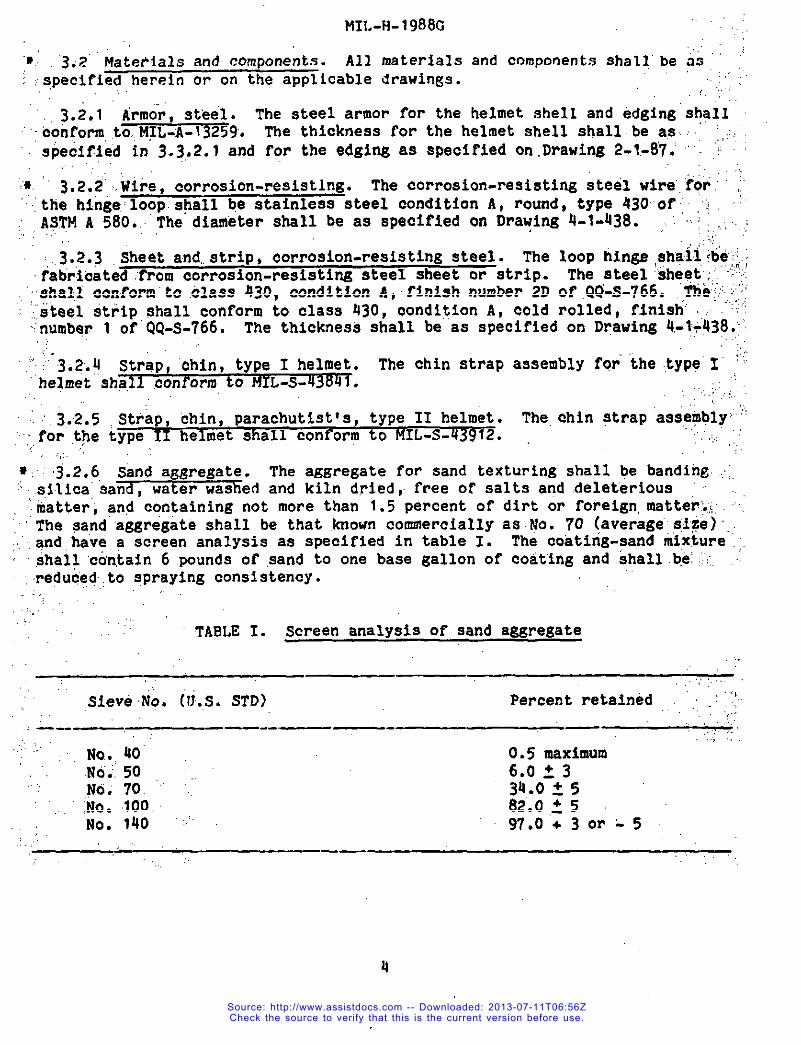
~ 3.2.6, Sand aggregate. The aggregatefor sand texturingshall be bsndihe..;:..silica”sand, water washed and kiln dried, free of salts and deleterious ~~ ...
hatter;and containingnot more than 1.5 percentof dirt or foreign,mstter:.i;‘.::The gand’aggregateshall be that .knOWnCommerciallyaSNO. 70 <aVeraS@:8fZe)”,..snd have a screen analysisae specifiedin table I. The ooating-sandmixture,;.shall ctin,tain6 pounds of sand to one base gallon of coatingand shallb.e!(:;..-~reduc”edtosprayingconsistency....
.,, TABLE 1. Screen analysis of sand aggregate
SieveNo. i~j.s.STD) Percentretained ,<<:..,
, ———— —-.——-
No,. UO 0.5 maximum.NQ;50 6.0 ~ 3.yo;70. “:’ 34.025No. 100. 02.0,25No. 140 ““ 97.0+30r-5
4
Source: http://www.assistdocs.com -- Downloaded: 2013-07-11T06:56ZCheck the source to verify that this is the current version before use.
MIL-H-1!X18G
f 3.7.7 (Wat.{nfl.The coat,in~ for finishingthe helmetshell (see 3.4.?)—.nhal1 t?onrormto MT1.-C-4fil(jfl,CO1or 01iVP Drab 34087or FEf)-3TD-’i9L.
3.3 Construction.The constructionshall conformin all respectsto thedrawingslistedin section2 and as specifiedherein. The finishedhelmetshellbe free of cracks, checks,wrinkles,dents,depressions,and rough andsharpedges. The type I and type II helmetsshall consistof the following:
a. Type I helmet - Assemblyof helmetshell,edgingand 2-hingeloop assemblies,togetherwith the attachedchin strapassemblyconformingto 3.2.4.
b. Type II helmet - Assemblyof helmet shell, edging and 2-hingeloop assemblies, togetherwith the attachedchin strapassemblyconformingto 3.2.5.
3.3.1 Spot welding. All spotweldingshall be as specifiedon thedrawings. Materialsto be weldedshall be clean and free of rust, scale,corrosion,oil, water,and othar foreignmatter. Spot welds ehall be freefrom pits,burn through,and flash. When testedin accordancewith 4.h.3. JJ,the spot welds shall pull a nuggetor buttonfrom the spot welded testspecimenswithoutany evidenceof failureof the veld.
3.3.2 Helmetshell. Prior to assemblingthe edging to the helmetshell,the helmetshell brim edge shallbe trimmedand groundsquareto the shapeshown on Drawings2-1-87and 2-1-88. The helmetshellsshall be formedso asto be free Prom stressrisersand stressconcentratedareas. When testedinaccordancewith 11.u.3.1, the helmetshellsshall show no evidenceof splittingor cracking.
3.3.2.1 Helmetshell thickness. The averagethicknessof the helmetshellprior to fi~ e not ess than 0.033 inchwith no singlethicknessm=surement less than 0.031 inch when tested ae specified in 4.4.3.1.Helmetshellsconformingto the above ehallmeet the ballisticresistancerequirementspecifiedin 3.5.
3.3.2.1,1 Alternatehelmetshell thickness. As an alternative,the averagethicknessof the helmetshell prior to finishingshall be not less than O.O34inch with no singlethicknessmeasurementless than 0.029inch,when testedasspecifiedin 4.4.3.1. Helmetshellsconformingto the above are not requiredto be ballisticallytested.
3.3.2.2 Helmetshellheat treatmentlot numberidentification.Thesuppliershall inciseor Indentthe steel suppliers heat treatmentlot numberon each helmetshell. The charactersshallbe legibleand visibleon theinsidesurfaceof the finishedhelmet.
Source: http://www.assistdocs.com -- Downloaded: 2013-07-11T06:56ZCheck the source to verify that this is the current version before use.
.:, :.,., ., MIL-H-1988G
:.,.::.”3.”3~~”Helmet shell edging. The helmet shell edging shall “conformto the>:,;,thicknesk;.w,i~th:;and configurationshown on Drawing 2-1-87. The edgiri,ahal~,’beepanked “tothe”helmetshell as shown”onDrawing 2-1-87with the inside“and’,outside;,$nne+edgeq:,fiiwnlypressed against thehelmet shell so that the ‘e.@@$~’~,are ~n”contact’k?i.hh.thehelmet shell around the entire periphery.
,’;,3.4,:,Fln$shof helmet shell.
+“.,,~g~.l:gupfl,ace..$reparation.The inside and outside surface of the.helm$..~”;“:she~~and edging and:’the>surfacesof the,hingeloops shall be cleaned, .’,,;.’“&&at.ed,, and primed in accordancewith tYPe F of UIL-T-704. The final ~rYl!M:.,””:.operationshall be conduotedin such a manner as to ensure thoroughdrylri&’ :’:,within .theedgingand hinge 100PS.
.,
,,:,., ,.
~.:.3.4.2 .Finish. Following the surface preparatlohand priming specified,iri’.’;:.3.4,1,. thxre helmet shall be coated with the coating speoi~ied,ih,3c2j7.’;A“coat of.the same coating containingthe aggregatespecifiedin 3.2.6.shall..””then bq;applieduniformlyon the outside ?urface of the helmetstkll and” :’::‘,
edging. ‘There’shallbe no sand Particlesonthe inside of the helmet shell...or,:edg$pg.,After drying and curing, the finish shall.beUniformin texture ..arid,;’;’.:’
:!ap~e;ranceandf?ee of=ags,,runs, wrinkles~chips, blistering~”flakingp”o?k:,‘peeling’. .’
“ ~.~,galli.gtio.resistance..,.,
Helmet shells conformingto the,thickness”,’ ,’”:+,,.requ’iti.e~ntof-3i.3*2..lshafl have a VP 50 bsllisticresi8@nce’1imit’ofnot:,”:...,.le”i&:;.than’’9OOfeet,pir s“econdwhen tested as specifiedin 4.4.30’?.!elmet” ;Y..“shells conforming,”to.,thealternatethicknessrequirement..of 3.3.2.1.1.arenot.””,“L..requi,redto.be teg”tedfor ballisticresistance.
,.
,: “3.6 Weight. The weight of the finishedhelmet, cOMPletewith chin.etr.aP’,;.:‘assernblzll.not exceed the weights indicatedbelow.&ijeirnetS.hall.be determinedby means of a scale that’has.tiinimtim’and is accurate to 1/8ounce minimum.
Type I Helmet’ - QO_l/4 ounces?ype II,Hel,met-40-1/8 ounces,..
The weight:of$th.e,.:{.,l/8ounce”gra@atfons’,.~,
!,
.3;7.’Workmanship.. The Finished helmet shall conform to the qualityof”,,j $~duct establishedb~.:,th$sdocumantand:’exceedthe a~pli~ble ,,aoceptablequality
the occurrenceof defiotsShall not,levels.
6Source: http://www.assistdocs.com -- Downloaded: 2013-07-11T06:56ZCheck the source to verify that this is the current version before use.
MIL-H-1988G
● u. QIJALITYASSURANCE PROVISIONS
4.1 Responsibilityfor inspection. Unless otherwise specified in theContractor Durchase order. the contractoris reSDOILSiblefor the Performanceof all inspe&.ionrequirementsas specifiedherei~. Except as otherwisespecified in the contract or purchase order, the contractormay use his ownor any other facilitiessuitable for the performanceof the inspectionrequirementsspecifiedherein, unless disapprovedby the Government. TheGovernment reserves the right to perform any of the inspectionsset forth inthis document.where wch inspectionsare deemed necessary to assure suppliesand services conform to prescribedrequirements.
4.?.1 Responsibility For compliance. All items ❑ust meet all requirementsof sections 3 and 5. The inspectionset forth in this document shall become apart of the contractor’soverall inspectionsystem or quality program. Theabsence of any inspectionrequirementin the document shall not relieve thecontractorof the responsibilityof assuring that all products or suppliessubmitted to the Government for acceptance comply with all requirementsof thecontract. Sampling in quality conformancedoes not authorize submissionofknown defectivematerial, either indicatedor actual, nor does it commit theGovernment to acceptanceof defective material.
4.1.2 Responsibilityfor dimensionalrequirements. Unless otherwieespecified in the contract or purchase order, the contractor is responsible foraseuring that all specified dimensionshave been net. Uhen dimensionscannotbe examined on the end item, inspectionshall be made at any pointpo~nt.sin the manufacturingprocens necesn,aryto assure compliancedimen.ninn:llrequlroment.t.
4.2herein
a.b.
4.3
ClassificationOr inspections. The inspectionrequirementsare classifiedas follows:
First article inspection (see 4..3).Quality conformance inspection (see 4.4).
First article inspection. when a first article is requiredit shall be examined for the defects specirled in 4.4.4 and 4.U.5.
or at allwith all
speciried
(see 6.2),The
presence of any defect shall be cause for rejection of the first article.
4.4 Quality conformanceinspection. Unless otherwise specified,samplingfor inspectionshall be performed in accordance with MIL-STD-105.
U.Q.I Component and material inspection. In accordance with 4.1,components and materials shall be inspected in accordancewith all therequirementsof referenceddocumentsunless otherwise excluded, amended,❑edified, or qualified in this document or applicable purchase document.
Source: http://www.assistdocs.com -- Downloaded: 2013-07-11T06:56ZCheck the source to verify that this is the current version before use.
MIL-H-1988G,,
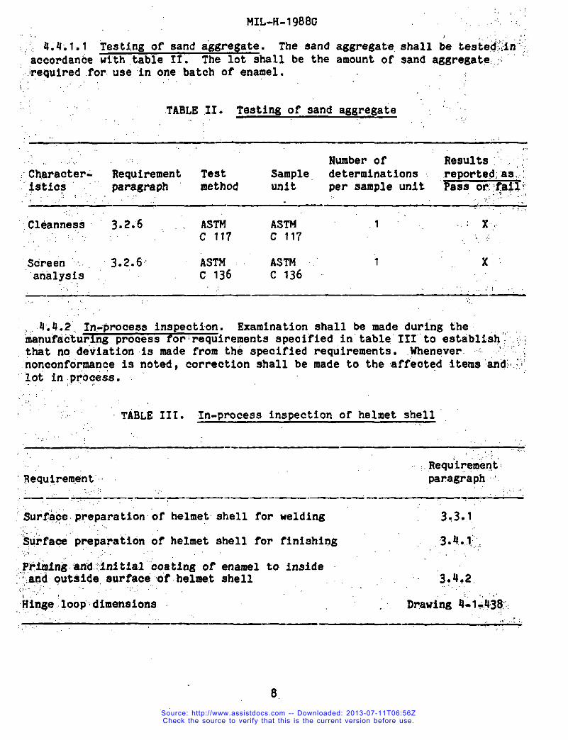
~~~~~4.4:.1.1Testi,ngof sand.a’aregate.The eand aggregate,shall be tested:;;in’”accordance with table II. The lot shall be the amount of sandaggregate.:
~requiredfor.use in onebatch of’enamel.,:,
.TABLE.11. Testingof sand aggregate . “ .,.,
,..,
. ... Number of Results:‘““.;~~”Ch,aracter- Requirement Test Sample determinations. .reporte@;:as.:,$$tia$ ““’ para~raph method Unit per sample unit pass on::faZl~-,... ..>.,...,,
,.. ,..
.Cleanness 3-2.6 ASTM ASTMc 117 c 11’?
3.2.6Screen .. . Mm! ASTM .’ i x’analysis c 136 C 136
.— — ,. -,.:,
.4.4.2”. In-process inspection. Examinationshall be made during the‘knuflicturimgprooessforrequirements speoifiedin’table’111’to estibliih,~”:j}that no,,deviationis made from the specified requirements. .,~enqver.nonconformance is noted, correctionshall be made to the affeoted items”and!.~~,..
‘~ot in,process.~~
TABLE 111. In-proceseinspectionof helmet shell
.,:...,-.— — ,,
.Requi:ernerit:“Requirernmt’ paragraph‘.
-— --__—.--— .,,!.——.—.—.— . ;.,
Sur.$aceireparationof helmetshell for welding 3.3.1,
‘&j;fa~ preparationof helmet shell for finishing‘.:..,PF~fng”an~.’?~nitfal”’co~tingof enamel to inside?:!jaridouttiide,surface”of.heln?e.tshell,:;,,.,:,,:..
,3.4....1::,
3~4,2.
Uin4eloop’dimensions Drawing 4-li,43&
8.
Source: http://www.assistdocs.com -- Downloaded: 2013-07-11T06:56ZCheck the source to verify that this is the current version before use.
MIL-H-1988G
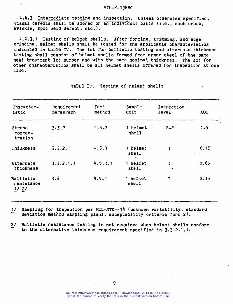
4.4.3 Intermediatetestingand inspection. Unless otherwisespecified,visual defectsshall be scored on an individualtiasis(i.e.,each crack’,wrfnkls,spot weld defect, etc.).
4.4.3.1 Testing of helmet shells. After forming,trimming,and edgegrinding,helmet shells shall be tested for the applicablecharacteristicsindicatedin table IV. The lot for ballistictestingand alternatethicknesstestingshall consfatof helmet shells formed from armor steel of the sameheat treatmentlot number and with the same nominal thickness. The lot forother characteristicsshall be all helmet shells offered for inspectionat onetime.
TABLE IV. Testingof helmet shells
—. ———- _— .——
Character- Requirement Test Sample Inspectionistic paragraph method unit level AQL
Stressconcen-tration
Thickness
Alternatethickness
Ballisticresistance1/ 2/——
.
3.3.2 4.5.2 1 helmet s-2 1.5shell
3.3.2.1 4.5.3 1 helmet I 0.15shell
3.3.2.1.1 4.5.3.1 1 helmet I 0.65shell
3.5 0.5.4 1 helmet I 0.15shell
Al Sampling for inspectionper MIL-STD-414(unknownvariability,standarddeviationmethod samplingplans, acceptabilitycriteriaform 2).
21 Ballisticresistancetestingto the alternativethickness
is not requiredwhen helmet shells conformrequirementspecifiedin 3.3.2.1.1.
9
Source: http://www.assistdocs.com -- Downloaded: 2013-07-11T06:56ZCheck the source to verify that this is the current version before use.
MIL-H-1988G., ,.
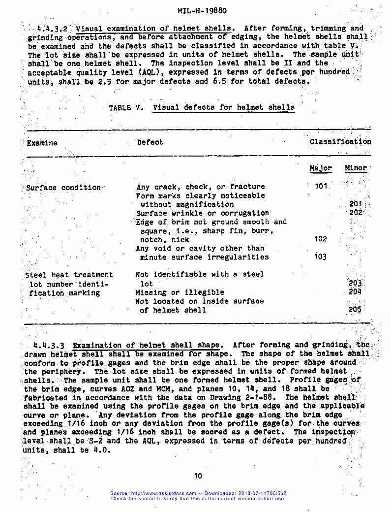
4.4..3c2’’Visual examinationof helmet shells. After forming,,trimmingand “,:.gri,ndin~operakionsl’ and beFore attachmentof edging,the hel@iStshells+ha.l!:‘..beexarninedand the defects shall be classifiedin accordance.with:,tab~p,,’?.$iThe”’lot’size shsll’beexpressedin units of helmet shells. Theaample unit:!
‘ shall”’beone.helrnetehell. The inspectionlevel shall be II and the “ “ “:,‘ acceptable.“quality”level (AQL),exwesaed in terms of defects per hun@?;;ij’units;stidl be 2.5 “formajor defectsand 6.5 for total de,fec$s.
,,. ,,:.,.,.
TABLE V. Vlsualdefects for helmet shells “.,”,
- ——.— .-,.,,
“:Exarnine Def’ect ,Classificat~on
—-.. —.— .— —
. .. ..
,:’.,.Surface condition:,,.
“iteel,he,attreatmentlot number’identi-
;,.ficati.on.marking
Major Minor;—,.
Any crack, check, or fracture ‘ 101. “; .’”Form marks clearlynoticeablewithout magnification ‘~oj:,
Surfacewrinkle or corrugation 2(32;,;
‘“Edgeof.brim not ground smooth andsquare, I.e., sharp fin, burr,notch, nick 102 .’”Any void or cavity other thanminute surface irregularities 103 ““
Not identifiablewith a steellot ‘~03;/
Missing or illegible 209Not locatedon inside surfaceof helmet shell 205~
~~ 4.4.3.3 Examinationof helmet shell shape. After formingand grinditii:‘<$$;:’.,drawr”.helrnetshell shall be examined for shape. The shape of the helmet;sh~~l;,::,eonfotimtoprofile gages and the brim edge shall be the proper”sbapearourid “’the.pe”riphi?r~.The lot size shall be expressedin units of formedhelmet; ,.,shellsi”.’,The sample unit shall be one formedhelmet shell. Profilegiiges’:ofthe brlrnedge, curves AOZ and MOM, and planes 10, 14, and 18 shall be “ “ ““fabricated in accordance with the data on Drawing 2-1-98. The helmet sheli:’”shall be examinedusing the profilegages,on the brim edge and the applicable“:curvecir.plane;‘“Anydeviationfrom the Profilegage along the Brim.edge..”ex6eedi~.1/16 inoh or any deviationfrom the profilegage(a) for.theourvesand plane’sexceeding 1/16 inch shell be scored aa a defect. The f*pect*o~,;lqye,lahall,,be’S-2and the AQL, expressedIn terms of defects per.hundred, ,,units,shall be 4.0.
.,,,,;,,
10
Source: http://www.assistdocs.com -- Downloaded: 2013-07-11T06:56ZCheck the source to verify that this is the current version before use.
MIL-?{-1988G,
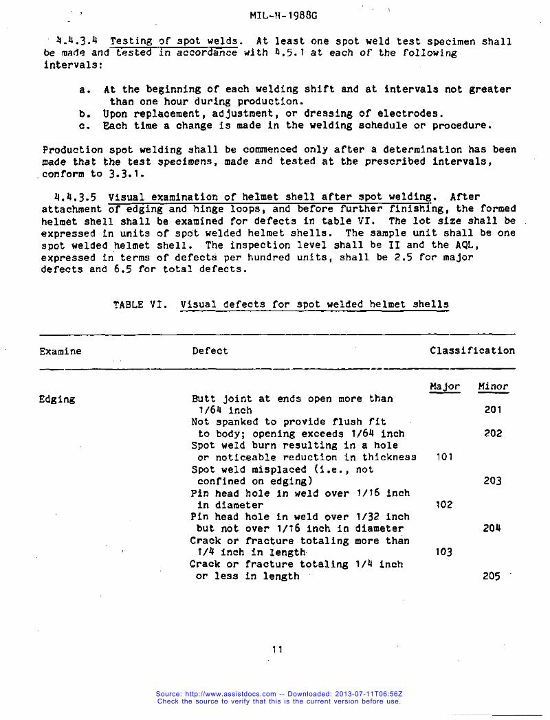
4.4.3.4 Testingof spot welds. At leastone spot weld test specimenshallbe made and testedin accordanceuith 4.5.1at each of the following
intervals:
a. At the beginningOf each weldingshift and at intervalsnot greaterthan one hour during production.
b. Upon replacement,adjustment,or dressingof electrodes.c. Each time a change is ❑ade in the weldingscheduleor procedure.
Productionepot weldingshallmade that the test specimens,conformto 3.3.1.
be commencedonly after a determinationhas beenmade and testedat the prescribedintervals,
ti.4.3.5Visual examinationof helmet sheIlafter spot welding. Afterattachment~ng, the formedhelmet shell shall be examinedfor defectsin tableVI. The lot size shsll beexpressedin units of spot weldedhelmetshells. The sampleunit shall be onespot welded,helmetshell. The inspectionlevel shall be II and the AQL,expressedin terms of defectsper hundredunits,shall be 2,5 for majordefectsand 6.5 for total defects.
TABLE VI. Visual defectsfor spot weldedhelmet shells
Examine Defect Classification
Edging Butt jointat ends open more than1/64 inch
Not spankedto provideflush fitto body; openingexceeds 1/64 inchSpot weld burn resulting in s holeor noticeablereductionin thicknessSpot weld misplaced(i.e.,notconfinedon edging)Pin head hole in ueld over 1/16 inchin diameter
Pin head hole in weld over 1/32 inchbut not over 1/16 inch in diameterCrack or fracturetotalingmore than1/4 inch in Iength
Crack or fracturetotaling1/4 inchor less in length
Major
101
102
103
Minor
201
202
203
204
205
11
Source: http://www.assistdocs.com -- Downloaded: 2013-07-11T06:56ZCheck the source to verify that this is the current version before use.
MII,-}1-1988C‘i
TABLE vi.:,,.Visual derect~ for spot welded helmet shells - Continued.,..... “ .,. ,,,..,..
Examine ‘,:: , ,. Defect Classiffatl.kii,,,.: ,.,. ., .,,.. -,
..:,.’.:!’:.,.,
Edgitig’- ‘eoht$n’u’ed
,.,.
Hinge.’loop” ~assembly ~
,,,
-“— .—, .—
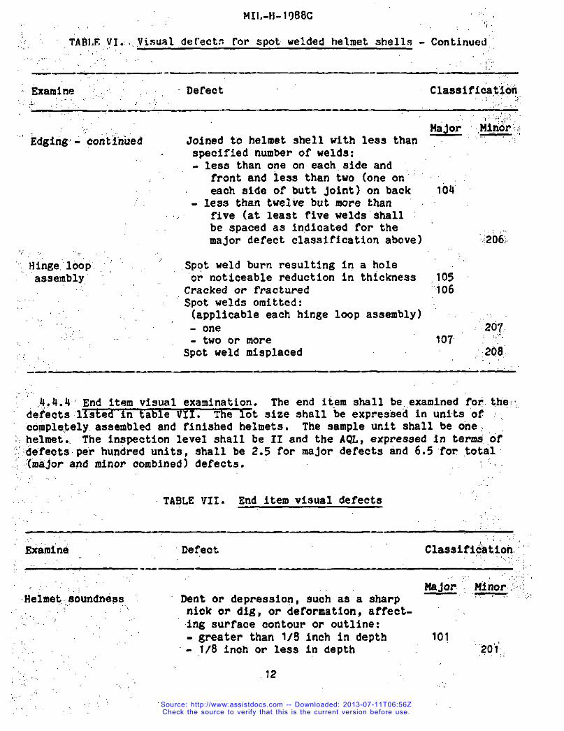
14Ej@ ,.,*::~Joined to helmet shell with less thanspecifiednumber of welds:- less than one on each,side and
front and lese than two (oneon’each aide of butt joint)on back 104less than twelirebut more than
,, five (at least five welds’ehell ~be spaced as indicatedfor the ,..,major defect classificationabove) :206;
.Spqtweld burn resultingin a hole ““‘or noticeablereductionin thickness .105Crackedor fractured “106Spot welds omitted:
, (applicableeach hinge looP assembly)- one 207:- two or more 107’ : “(-”Spot weld misplaced :,208
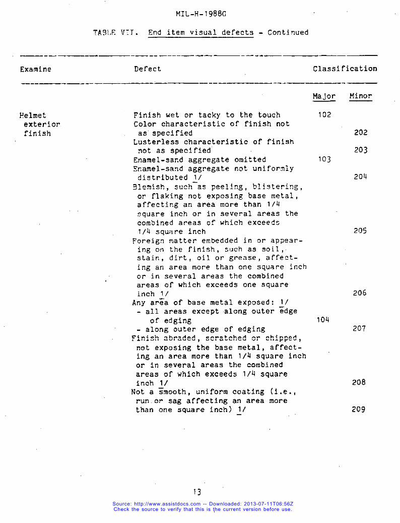
‘,.;“ ,4,.4.4”End item visual examination. The end item shell be..examinedfor.t,he.:defectslisted in’table VII. The lot size shall be expressedin Units of :,.cornple,tely.assembledand finishedhelmets. The eampleunit shall be one,
, helmet...The Inspectionlevel shall be II and the AQL, expressedin termti‘of~defectaper hundredunits, shall be 2.5 for major defectsand 6.5for .tOtal
‘:(rnajor and minor combined)defects. ,.,.
TABLE VII. End item visual defects
— —.,!,
‘&amine Defeot., Claaaificat:ion.’
.——,..
:. Major.’Mirror..;;:Heimet,.:,60undnea:,, Dent or depressio~,such as a sharp — ‘-.’ .,..!
:,”.’ ., niok OF dig, or deformation,affect-ing surfacecontouror outline:- greater than 1/9 inch in depth 101
- 1/8 inch or less in depth,:.;201,.
,.
12,,, ,’ .,,
,..,.: Source: http://www.assistdocs.com -- Downloaded: 2013-07-11T06:56Z
Check the source to verify that this is the current version before use.
MIL-H-1988G
TA91,EVIT. End item visual defects - Continued
—.—— —.—— -—-.—.--————-.--— —.—
Examine Defect Classification
._-—.—.-—.——- —- ——— ——-. .— .—
Major Minor——
Helmet Finish wet or tacky to the touchexterior Color characteristicof finish notfinish as”specified
Lusterlesscharacteristicof finishnot as specifiedEnamel-sandaggregateomittedSnamel-sandaggregate not uniformlydistributed1/
~lemish, such-as peeling, blistering,or flaking not exposing base metal,affeCtingan area more than I/q$quare inch or in several areas thecombinedareas of which exceedsl/Q square inch
Foreigz matter embedded in or appear-ing on the finish, such as soil,stain, dirt, oil or grease, affect-ing an area more than one square inchor in several areas the combinedareas of which exceeds one squareinch 1/Any ar=a of base metal exposed: 1/
all areas exceptalong outer =dgeof edgingalong outer edge of edging
Finish abraded, scratchedor chipped,not exposing the base metal, aFfect-ing an area more than 1/4 square inchOr in SeVeral areas the combinedareas of which exceeds 1/4 squareinch 1/Not a =mooth, uniform coating (i.e.,run.or sag affectingan area morethan one square inch) 1/—
102
202
203103
20U
205
206
104207
208
209
13Source: http://www.assistdocs.com -- Downloaded: 2013-07-11T06:56ZCheck the source to verify that this is the current version before use.

MIL-H.l~98G ...:
TAgLE VII, End item visual defects - Continued.
., ,, ,.,..,,-—..—. —. —.- ——...—--- —
.:..;’Examine‘ ~~.. Defect classifiaat~o~’
?,i,.,—- ..—,.,..:..’..,.:.,,.,:,.
,Heimet..”“’.ipteriok.ritiisti,, ,. ,
,.
,.
‘Edging ,’
..,’:,... ... .
~‘Hinge’loopa’ss”embl,y
,.
Finish wet or tacky to the touchEnamel finish omittedAny area of base metal exposed~1Blemish, such as peeling,blisteringor flaking,or abracle.d,scratchedorchipped’finish,not exposing base “’“metal,affecting’anarea more than”one square inch or in several.areasthe combinedareas of which exceedsone square inchForeign matter embeddedin or appear-ing on the finish, such as soil, :.:stain, dirt, oil or grease.,aFfect-ing an area more than one square’inch 1/
“EnamelZsandaggregateoverrun affect-ing an area which extends beyondthe edge 3/8 inch ormore inanyone area?Jota smooth, uniform coating (’i.e.,run or sag affectingan area morethan one square inch) 1/
OmittedSharp or rough edge (includingweldflash not removed)
Om+ttedAny componentdamagedor malformed,affectingproper functioningLoop does not move freely within“hingewhen manual force is applied
.Sharp or rough edge (includingweldflash not removed)
Area of no finish,exposingbasemetal for an area greater than1/4 inch in longestdimension,exceptat moving joint surfaces that aresubject to friction
Major :.Uiikr’”— . -.
105 ‘“106, :107.~~
,’2:10
,21i
:;;21.2
.21:3.
Ioa. :“:”
109
110
Ill
,,21,4,,,
.:>1,5.:,
216
,,
14
Source: http://www.assistdocs.com -- Downloaded: 2013-07-11T06:56ZCheck the source to verify that this is the current version before use.
!41L-H-1988G
TA9LE VII. End item visual defects - Continued
.—— — —.————— .---— ——. —-- -—
Examine Defect Classification
——— -———
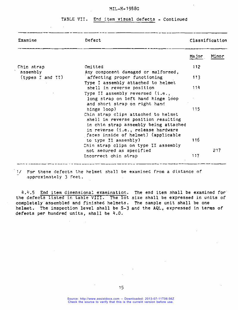
Chin strap omitted‘ assembly Any componentdamagedor malformed,
(typesI and 11) affectingproper functioningType I assemblyattachedto helmetshell in reversepositionType II assemblyreversed (i.~.,long strap on left hand hinge loopand short strap on right handhinge loop)Chin strap clips attachedto helmetshell in reverse positionresultingin chin strap assemblybeing attachedin reverse (i.e., releasehardwarefaces insideof helmet) (applicableto type 11 assembly)Chin strap clips on type 11 assemblynot secureda.sspecifiedKncorrectchin strap
Major Minor—.—
112
113
114
115
116
217117
—- .—_— _____ .-._____—___—-—__ —.--——-———.—
1/ For these defects the helmet shall be examined from a distanceofapproximately3 feet.
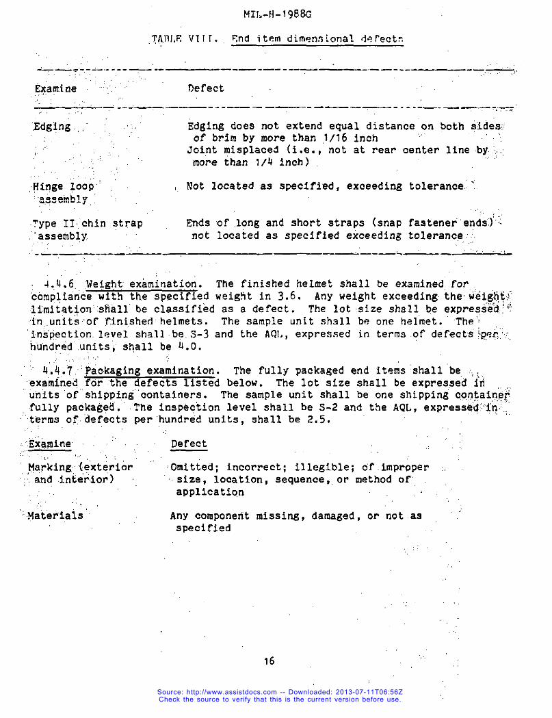
4.4.5 End item dimensionalexamination. The end item shall be examinedfor’the defects listed in table VIII. The lot size shall be expressedin units ofcompletely’assembledand finishedhelmets. The sample unit shall be onehelmet. The inspectionlevel shall be S-3 and the AQL, expressedin terms ofdefects per hundred units, shall be 4.0.
Source: http://www.assistdocs.com -- Downloaded: 2013-07-11T06:56ZCheck the source to verify that this is the current version before use.
MIL-H-1988G
,~JilI,F,v~lr. F,nditem dimensionaldeKectn
_~ .....--...--—-—— ———-—.—----—— —-. —— ___~—- —--,
Ex,arn.ine .‘’:“ “‘ Defect
-r ----— ——---——— —--— ———--- .---—-— —- —.-.,, . ..
Edging.,,” ~ .’
,. ,.
,-iinge~ooi’‘a.+seinbly,~
Type IIchin strap.<assembly
Edging does not extend equal distanceon both iides;of brim by more than ,1/16inch “Joint misplaced (i.e.,not at rear center line by.:more than 1/4 inch)
Rot locatedas specified,exceedingtolerance.-’.
Ends of.long and short straps (snap fastener’endi”)not locatedas specifiedexceedingtoleranc~,:j
- —.——-.-—— ———-—. -— ‘, ,.
.,,;
4.,4.6.:Weightexamination. The finishedhelmet shall be examinedfor,.,compliai,cewith the specifiedweig!itin 3.6. Any weight exceedingthew’eigti&Ifmitation”siiall’be classifiedas a defect. The lot.sfzeshall be expre:ied,::~‘in,,units$of”~ini,shedhelmets. The sample unit sh~ll be one helmet. The’“ins’pecti,on.level shallb~.5-3 and the AOL, expressed in terms.ofdefects!P&.,
huhdrid’.unitsishall be 4.0.
““ 4’~4.~’fackagingexamination. The fully packagedend items:shallbe,.,1,‘exami”ne~forthe defectslisted below. The lot size shall be expressediriunits of”’shipping”containers.The sample uni”tshall be one ShiPpingCOg,@ip+~fully packaged”.The inspectionlevel shall be S-2 and the AQL, exPress&d!’’+n..
“terms ofdefects per”’hundredunits, shall be 2.5.
:,;:Exarnine : Defect..!.,,,..,..,,,Marking(:exterior ““ Omitted; incorrect;illegible;of.improper :.:;.and interior) size, location,sequence,,or method of”
application.:,.,
‘.Materials’ Any componentmissing,damaged,or not.as “specified
16
Source: http://www.assistdocs.com -- Downloaded: 2013-07-11T06:56ZCheck the source to verify that this is the current version before use.
MIL-H-1988G
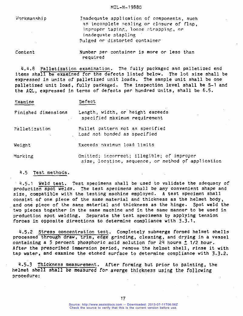
i!orkmanship Inadequateapplicationof components,suchas incompletesealing or closure of flap,impropertapinfl,loose r.trappinfl,orinadequ.st.estapling
Pulged w distortedcontainer
Content Number per container is more or less thanrequired
4.U,8 palletizationexamination. The fully packaged and palletizedenditems shall be examined for the defects listed below. The lot size shall beexpressed in units of palletizedunit loads. The sample unit shall be one’palletizedunit load, fully packaged. The inspectionlevel shall be S-1 andthe AQL, expressed in terms of defects per hundred Units, shall be 6.5.
Examine Defect
Finished dimensions Length, width, or height exceedsspeci?iedm~ximurorequirement
PdlletIzation ?allet pattern not as s?ecifiedLoad not bqnded as specified
Weight F.xceedsmaximum load limits
qarking Omitted; incorrect;illegible;of impropersize, .loc2tion,sequence , .or method of application
4.5 Test methods.
4,5.1 Weld test. Test specimens shall be used to validate the adequacy ofproductionspot welds. The test specimens shall be any convenientshape andsize, compatiblewith the testing machine employed. A test specimen shallconsist of one piece of the same material and thickness as the helmet body,and one piece of the same material and thicknessas the hinge. Spot weld thetwo pieces together in the same machine and in the same manner to be used inproductionspot welding. Separate t-hetest specimens by applying tensionforces in opposite directions to determine compliancewith 3.3.1.
4.5.2 Stress concentrationtest. Completely submerge formed helmet shellsprocessed through draw, trim, edge grinding, cleaning, and drying in a vesselcontaininga 5 percent phosphoricacid solution for 24 hours Z 1/2 hour.After the prescribed immersionperiod, remove the helmet shell, rinse it withtap water, and examine the etched surface to determine compliancewith 3.3.2.
4.5.3 Thickness measurement. After forming but prior to painting, thehelmet shell shall be measured for averge thicknessusing the following
procedure:
17Source: http://www.assistdocs.com -- Downloaded: 2013-07-11T06:56ZCheck the source to verify that this is the current version before use.
,...
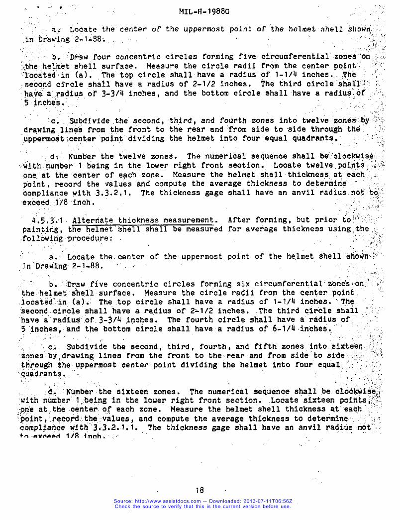
.,, ,.. a. Locate the
flinDFaw~ng’2”-l-98...
MIL-H-1988G.’,,,,.
,,... .,,..’,
center of the uppermost point of the helmetshell .,shown~.:.,...:,,,.::::
.’,.;.:,,,,.,,;,<,,. ,..,,.-:, b,’”:Drawfour c~ncentriccircles forming five Circumferential’.zone”..ononj<.::.;<~tie:he,lrnetshell ,surface. !.leasu~ethe circle radii from the center point”, ‘;fl’“~ocatedin (a). The”top circle shailhave a radius of 1-1/4 inches, ,The,:.,secondcircle shall have a radius of 2-1/2 inches. The third.circlesh~~~’.;”j;~,
:ha,vea::r.adius,o~3-3/Q snches,and the bottom circle shallhave a radiuS’O:f”’:::.5incheS”.:..,,
‘c. Subdividethe”second,drawing line% from ,thefront to.uppermo$t;.center‘pcint’dividing
,. . ....
third, and fourthzones into twelve’%one%.by~~<’;the rear and ‘fromside to side through ttje. :;the helmet into four equal quadrants. ‘-,..,,’:.L
.
. d; Number the twelve zones. The numerical sequence shallbe”!clockw:se(~.wi.th.,pumber1 being in the lower right front section.,Locate twelve,~iq,tS:S::y,.oneat the‘centerof each zone. Measure the helmet shellthickness,ateach,,,obint. record the values and oomvute the average thicknessto detemiirie’- ..::,~ornpl~an.cewith 3.3.2.1. The thicknessgage shall have an anvi~”radiu&no&to~~exc@ed:lj8inch.
,4.5.3.1 Altertiatethicknessmeasurement.pain.tirig,the helmet’$hellshall be measuredfollowitigprocedu,re:
,,.,,,. ,a..’Locate theeenter of the uppermost.iri’’DrawIng2-l-88, “ . ~
,: ,.
After forming,but prior to~;’”:~’for average thicknessu%ing.{t,he,;,
,;;’::,,!,,,..
point of the helmet Shell ‘shown;:’i”
,. ,.:,,,,”‘:,.,:
b’.Draw five concentriccircles formingSix circumferential’Zon’e’suon,:“~~j‘~he’helrne~shell’surface.Measure the circle radii from the center’PoinE. ‘“’”.locat”ed’’+n:(a. );, The top circle shall havesecond.,c,ircl.e?hallhavea ‘radiusof 2-1/2tja.vea“rad’iu+[.oC.3-3/~inches. The fourth5’inches,anclthe bottom circle shall have.: ::::(~~ . :,
C:O Subdivide the second, third, fourth,and fifth zones “intosix~ti$n:~~~~izones’by,,drawing,linea‘fromthe front to the.rearand from sidi‘tos,tde”:::;:i”’~;throyghth~gppermtist centerpoint dividing the helmet into !’ourequal;’;i~~~~~.“:quadrant?.,, “, . .
.. ..... ,..
a radius of 1-1./4inches.‘“T:he ‘“inches. .’fhethird circle shall.,;’~”,”circle shall have a“radiuso~:;.”:a radius of 6-1/4ineh~s. .,;’’,.:,
{:;.,’:
... .,. ,. ...,,. ‘, :,,..,.,
,d..Nu,mberthe sixteen zonea. The numericalsequencea@ll be.cloc~i$$~with ‘number”~;belngin the lower right f’rent$ection. Locate sixteen p,oint,a;;;..~oneat,the .center.of each zone. Measure the helmet shell thich%$s at”’e+?h.’:.’?$o~nt,’..~ecordthe:values,s,and compute the average thicknessto determine,~,::;compl$an.cewith”3Y3.2:.l.l.,,The thicknessgage shall have an anvil ?ad$Usnot’””:,‘+.o..eveeed1/8 .i.neh,:
,..,
18Source: http://www.assistdocs.com -- Downloaded: 2013-07-11T06:56ZCheck the source to verify that this is the current version before use.
. .. .MIL-!-I-1988G
G.5.4 Ballistictest. After forming,trimming,and edge grindingof helmetshells has been done, tests to determinecompliancewith the ballisticresistancerequirementof 3.5 shall be performedin accordancewithMIL-STD-662,except that the weight of armor test material requirementin”MIL-STD-662shall not apply. Testing shall be accomplishedby ‘firingone shoteach into at least ten of twelve sections,startingwith the lower right Frontsectionand continuingclockwisearound the lower zone and proceedingwitheach next higher zone in the same manner until the requirednumber of sectionshave been tested. If additionalshots are required;testing shall becontinuedby repeatingthe firing sequenceand stoppingwhen sufficientdatahave been obtained to per~it calculationof the Vp 50 limit.
4.5.4.1 Target area. Rigidlymount the helmet so that the area subjectedto impact shall be normal to the line of fire. The area to be tested isdesignatedas follows: Using as a center the uppermost point of the helmet asshown on Drawing 2-1-88, draw four concentriccircles 1-1/4 inches apart,measured along the surface. The top zone is not to be fired. Furthersubdivideeach of the remainingthree zones into four sectionsby drawingmeridionallines through the uppermostcenter point. This will divide thehelmet into quadrants.
4.5.4.2 yp 50 calculations.The Vp 50 limit for each test helmet shall bethe average of the velocitiesrecorded for ten fair impacts,consistingofrive lowest velocitiesrecorded for complete penetration,and of the fivehighest velocitiesrecorded for partial penetration,provided the spread forthe ten velocitiesused is not greater than 125 feet per second. In caseswhere the spread is greater than 125 feet per second, the Vp 50 limit shall bethe average of fourteenfair impactvelocities, consistingof seven lowestcomplete penetrationvelocitiesand.the seye.nhighest partial penetrationvelocities. All velocitiesused in these’’calculationsshall be strikingvelocitiescalculatedat the point of initial contact with the test helmet. Afair impact results when a projectilestrikes an.unsupportedarea of the testhelmet at a distance of at least 1-1/4 inches from any other point of impact.
5. PACKAGING
5.1 Preservation. Preservationshall be level A.
5.1.1 Level A. Five helmets of one type only, with the long and short chinstraps placed on the outside of each helmet except t,hestraps shall be insidefor the bottom helmet, shall be nested compactly,together in a stack with aseparatorbetween each helmet. The separatorshall be made of embossedorindentedpaperboardhaving a basis weight of not less than 48 pounds per 1,000square feet after embossingor indentation,or the equivalent (i.e.,Shocksorb,Waffleboarc!,or Trunk Wrapper). The separatormay ‘alsobe made ofl/8-inchminimum thicknesscushionin~material confortninRto PPP-C-1797. Theseparator90-degree
shall-bea disc of approxi~ately17 inches in ~iameter,slottedatintervalsaround the perimeterso that the disc will fold to the
19
Source: http://www.assistdocs.com -- Downloaded: 2013-07-11T06:56ZCheck the source to verify that this is the current version before use.
:etia.pe.”of”the helmet.’insideo.!:”eachhelmet
:sensitivetape., ..,.,’:’: ,’
MIL-tI-1988G
Prior to nesting, the hingeshall be completelycovered
loopwith
assemblieson t~~.’ ‘;;,,clothbacked pres”sure
,5.2”Pae:ing. Packing shall be level A or B, as specified(see’6.2)..... ...... .k,,:..5.~.,7,LevelApaoking. Twenty helmets of one type only, DreSerVedas,?Spectf.ied’in”5.1;ahall be packed in a fiberboardsl?ipPingcontaine~ :[con~ormlngto style RSC-L, grade V2S of PPP-B-636. The insideof each,.t,. ...,.j:flb,erboardcontainershall be.Pittedwith a box liner conforming,totype’!CF,.””;(,:,.,cl~s.q,:weather.resistant,varietySW, grade V3C of PPP-B-636. In additignp:{““”;~””~’
,~’each.:c,on.tainershall beprovided with a full-height,half-slottedstyle.“:’ ,,inteb,loc”kingpartitionor full-heightscoredand folded fiberboardsheets’.:,<;j~:
“fabricated of the’same materialas the box liner to form fourc.ellskikh.~rikhe.?~doritainer.Each nested stack of five helmetsshall be Packed uPrif3ht’(ctioufis’:@oF,h@lrnets””up)’within each of the four cells. The,insidedimensionsof.the~,;,:,:jihipp”ing’cotitiainer shall be approximately23 inches in length, 19-3/4inch6k”’:;:j:;in.wid.th,.and. 13-3/4inches in depth, Approximatedimensionsare”furni?h,ed.:a;s,.a,’guldeonly.. Each fiberboardcontainershall be closed inaccordance wi~~~::’’”}~rnektiod111,”.wat’erproofedin.accordancewith methodV, and reinfo.rced;agy):’.$;~;’!“~pecifjedin the appendixof PPP-B-636excePt that [email protected]’be;im::,:~‘accord$ncew.ith4.4.’7.’Shippingcontainersshall be ar~anged‘inunit loads.tn:i~{.,’accordance’with MIL-L-35078for the type and class of load speciiied(se~:::v’::”;fj.2). When unitlga~s are strapped;strappingshall be limited to nontiet~l~ic~.’~~9t:rappingi.except.”for type 11, clasg F loads.-
,,
● 5.2.2Level ,8‘pack~qg..’Specified,.in5.1, shall be
Twenty helmetsof one type only, preserved:aspacked in a fiberboardoontainerconformirigto
.“’e.t,yleRSC-L, t.ypeCF (varietySW) or SF, class domestic, grade,350of ,“:;P?P-B-636.:’’?tieinsideof each fiberboardcontainershallbe fittedwith ’a,,box..linercoriform’~ngto type CF, class domestic,variety W, grade 200 of .“:’::;:!.Pl?P-B-636.,.In’.addition,each containershall be providedwith a full-h”eigh~’~;half-slottedstyle interlockingpartitionor full-heightscoredand folded” ~~~
‘:fiberboardaheetifabricated of the same material as the box ‘linerto”’forin~totir.tiells ‘within‘thecontainer. Each nested stack of five helmets.shall:,,be,packed,,,upr+ght:(cnowns of helmetsup) within each of the four cells..In.@de ,..dimension?of each shipping’containershall be approximately23 inches,~ri, ~’length, 19-3/~.,inchesin width, and 13-31Q inches in depth. Approximate ~
:,dimensionsa~e furnishedas a“guide”only. Each Fiberboardcontainer?hfill..be’‘~.”’closedln:accordance with method II as specifiedin the appendixof PPP-B-63’6~:,exce’pt.that”the inspectionshall be in accordancewith b.4.7.‘ .,
* 5.2;2..l:’Weather-res$btantcontainer. When specified(ace 6.2), the.:chip.pingtiontaig?r.:ehall be a grade V3C, V3S, or V~s Fiberboardbox fabr$ea.t@k!A:In’accordancewfth’PPP-B-636and closed in accordancewith method’111 asspecifi80f,n”the ‘appendixof .PPP-B-636except that the inspectionshal”lbe @
;accot?daricewith.,4.U.7.,
:.,.:20
I Source: http://www.assistdocs.com -- Downloaded: 2013-07-11T06:56ZCheck the source to verify that this is the current version before use.
MIL-H-1998G
5.3packed
Palletization. When specified (see 6.2), helmets of one typeonly,as specifiedin5.2.2, shall be palletizedon a 4.way entry pallet in
accordancewith load type Ia”of MIL-STD-1U7. Pallet type shall b~ type I (4-way entry), type”IV or type V in accordancewith MIL-ST9-147. Each preparedload shall be bonded with primaryand secondarystraps in accordancewithbondingmeans K and L or film bondingmeans O or P. Pallet patternshall benumber 90 in accordancewith the appendixof MI~-STD-147.
5.U Marking. In addition to any specialmarking requiredby thecontractcm purchaseorder,“shippingcontainers,and palletizedunit loads shall bemarked in.accordancewith MIL-STD-129.
6. NOTES
6,1 Intendeduse. The helmets are intendedfor use with the Liner, GroundTroops’Helmet (Combat)per MIL-L-41800. The type I helmet is for use byground troops and the type 11 helmet is for use by parachutists.
6.2 Orderingdat~. Acquisitiondocumentsshould specify the following:
a. Title, number, and date OF this document.b. Type required !see 1.2).
When a ?irst article is required (see 3.1,.4.3, and 6.3).:. Selectionof applicablelevel of packing (see 5.2).e. Type and class of unit load required (see 5.?.1).r.. When weather’-resi.stantgrade fiberboardshippingcontainersare
requiredfor level 3 packing (see 5.2.2.1).E. When p~lletizationis required (see 5.3).
6.3 First article. When a first article is required,it shall be inspectedand approvedunder the appropriateprovisionsof FAR 52.209. The firstarticle should be a preproductionsample. The contractingofficer shouldspecify,theappropriatetype of first article and the number of units to befurnished. The contractingofficer should includespecific instructionsinall acquisitioninstrumentsregardingarrangementsfor selection,inspection,and approvalof the first article.
6.4 Subject term (keyword) listing.
Body armorHeadgearHelmet
Source: http://www.assistdocs.com -- Downloaded: 2013-07-11T06:56ZCheck the source to verify that this is the current version before use.
MIL-H-1988C
.“.,&~5 ,Change~”’&ompreviousissue. The marginsof this document’areaia@ec&!v~with an asteri,sk(?) to indicatewhere changes(additions,m?di”fications+.’!;i;..-:,.:cor.rect.ions~’de~etlons.,),from the previousissuewere made. This was.,dcvi~+$,$~~~.conveniencegnlii.arid..the“Governmentassumesno liabilitywhats?”everFor: a~x“:inaccuraciesin thesenotations. Biddersand contractorsare caqtioned’’’ti&l&flflevaltite ‘there.guirernentsof thi? document baeed on the.entire.com~e?ti~a?’;!’j:
...;;
:’.titiitten’,.i~re,sp,~ctiveof the mar8inal notations and. relationsh,i~ @th’s.,l~:!,.~$re~$ouais?ue’.’?,. !..,,..:,,.,:.,,,,.,,,,.., ,...clls$,ti~i,an~:““”‘.’.1 Preparingactivity
&Ar;$’’-:ck””’.““’“ Army - CL:;;.’Najy..-’,,Nu.!’ ,.,i.’”:Air.Force.- 99 ProjectNO. 8Q70-0122,..,-,...... .
;,;:Re:viewactiv~.ties:,: :,.,.,,.:.
~~~:,Army -:,MDAir Foqc.e-.82.,’:’.DPSC’:;-!Fs,,
.Usei,a’ctiv’iti~k:‘,,, ,
:..:,:.,Navy-“ MC,’:YD’i !,,;.AjrFoq.ce - Q5
,,
22
Source: http://www.assistdocs.com -- Downloaded: 2013-07-11T06:56ZCheck the source to verify that this is the current version before use.
t . -., -STANDAF!DIZATION DOCUMENT IMPROVEMENT PROPOSAL——— --
{Seehutmctium - R~ .Wc)
WCWWNT NuMBEP ‘2.DOCUMENTTITLE
MIL-H-1988G Helmet; Ground Troops ‘; Parachutists, Steel, M-1,NAMEOPSUeW1l’llHGO*C+!zAT~ON ●,Tv*COF0nG4NlZA110MlmaraWI
❑ VENDOR
•1 uSEn
A00nE6s(sm.:.city.EJ1.*.21?C*J
c1 MAN UFACTUfiEfl
n OTMEn (s-cm).
..— — .— —-. —-PFIOBLEM AREAS
. P.omra!l! N.w!bw ,fld W.xdlw
b. R9cOf,.m.d.a Wc.dne:
. %.xo”fn.,lo..l. 10?%.xm”u”d..w. ”
REMARKS
—-NAME OF .9uBMlT1En -I, ~lnl,Ml)- Ogti~d b.WORM TELEPMONENUMBER (l-dudAIW
Ca) - Op,lom.1
IAILINOADDnE5 (3Tmd.Clb,8ab.2/?Cd} - 00,10.uI t DATE O@ SUaMISBlON/YYMM/JD,
In m.- . .AmIll-!Rm.la71i wwwow ED1710MIS 0-OLETE.
Source: http://www.assistdocs.com -- Downloaded: 2013-07-11T06:56ZCheck the source to verify that this is the current version before use.