Embed Size (px)
Citation preview
MIL-C-85485A10 May 1983SUPERSEDINGMIL-C-8548516 September 1981
CABLE, ELECTRIC,
MILITARY SPECIFICATION
FILTER LINE, RADIO FREQUENCY ABSORPTIVE
This specification is approved for use by all Departments andAgencies of the Department of Defense.
1. SCOPE
* 1.1 EsQE!2” This specification covers the requirements for radiofrequency absorptive component wires and finished cables which function electri-cally as distributed low-pass filters. Materials and construction details arespecified in the applicable specification sheet.
1.2 Classification. Products in accordance with this specifi-cation shall be of the following types, as specified in the applicable specifi-cation sheet.
Component Wire A single conductor, insulated as specified in theapplicable specification sheet.
Finished Cable Any construction other than comp&ent wire, utilizinga wire or wires with or without shielding, or with orwithout an outer jacket.
1.2.1 Current ratinq. Theaccordance with MIL-W-5088.
1.2.2 Temperature ratinq.the component wire or finished cable forthe applicable specification sheet.
1.2.3 voltage rating. The
current rating shall be determined in
The maximum conductor temperature ofcontinuous use shall be as specified in
maximum voltage rating of the componentwire or finished cabl-efor continuous use shall be as specified in theappli-cable specification:sheet. .,
Beneficial comments (recommendations, additions, deletions) and any pertinentdata which may be of use in improving this document should be addressed to:Commanding Officer, Naval Air Engineering Center, ESSD, Code 93, Lakehurst,NJ 08733, by using the self-addressed Standardization Document ImprovementProposal (DD Form 1426) appearing at the end of this document or by letter.
FSC .6145
1:
Downloaded from http://www.everyspec.com
MIL-C-85485A
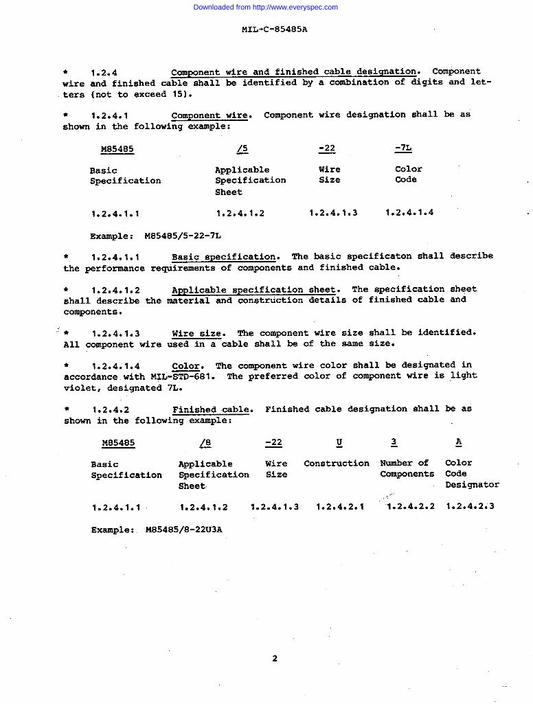
● 1.2.4 Component wire and finished cable designation. Componentwire and finished cable shall be identified by a combination of digits and let-ters (not to exceed 15).
● 1.2.4.1 Component wire. Component wire designation shall be asshown in the following example:
M85485 /5 -22 -7L—
Basic Applicable Wire ColorSpecification Specification Size Code
1.2.4.1.1
Example:
* 1.2.4.1.1
Sheet
1.2.4.1.2 1.2.4.1.3 1.2.4.1.4
M8548515-22-7L
Basic specification. The basic specification shall describethe performance requirements of components and finished cable.
● 1.2.4.1.2 Applicable specification sheet. The specification sheetshall describe the material and construction details of finished cable andcomponents.
;’● 1.2.4.1.3 Wire size. The component wire size shall be identified.All component wire used in a cable shall be of the same size.
* 1.2.4.1.4 Color. The component wire color shall be designated inaccordance.with M>L-STD-681. The preferred color of component wire is lightviolet, designated 7L.
● 1.2.4.2 Finished cable. Finished cable designation shall be asshown in the following example:
M85485 /8 -22 Q ~ A—
Basic Applicable Wire Construction Number of ColorSpecification Specification Size Components Code
1.2.4.1.1
Example:
Sheet Designator....-
1.2.4.1.2 1.2040103 1.2.4.2.1 ‘lo20402e2 1*2D402.3
M85485/8-22U3A
2
Downloaded from http://www.everyspec.com
MIL-C-85485A
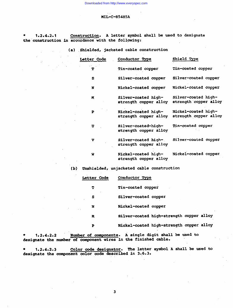
Construction. A letter symbol shall be used to designateaccordance with the following:
* 1.2.4.2.1the”constructlon in
Shield Type
(a) Shielded, jacketed cable construction
Letter Code Conductor Type,..
T
s
N
M
Tin-coated-copper Tin-coated copper
Silver-coated copperSilver-coated copper
Nickel-coated copper Nickel-coated copper
Silver-coated high-strength copper alloy
Silver-coated high-strength ”copper alloy
Nickel-coated high-strength copper alloy
Nickel-coated high-strength,copper alloy
P
Silver-coated-high-strength copper alloy
Tin-coated copperu
Silver-coated copper
Nickel-coated copper
v Silver-coated high-strength copper alloy
Nickel-coated high-strength copper alloy
w
(b) Unshielded, unjacketed cable construction
Letter Code Conductor Type
T Tin-coated copper
s Silver-coated copper
copper
high-strength
high-strength
N Nickel-coated
M Silver-coated copper alloy
copper alloyP Nickel-coated
● 1.2.4.2.2 Number of components. A single digit shalldesignate the number of component wires in the finished cable.
be used to
toshall be used● 1.2.4.2.3 color code designator. The letter symbol Adesignate the component color code described in 3.6.3.
Downloaded from http://www.everyspec.com
MIL-C-85485A
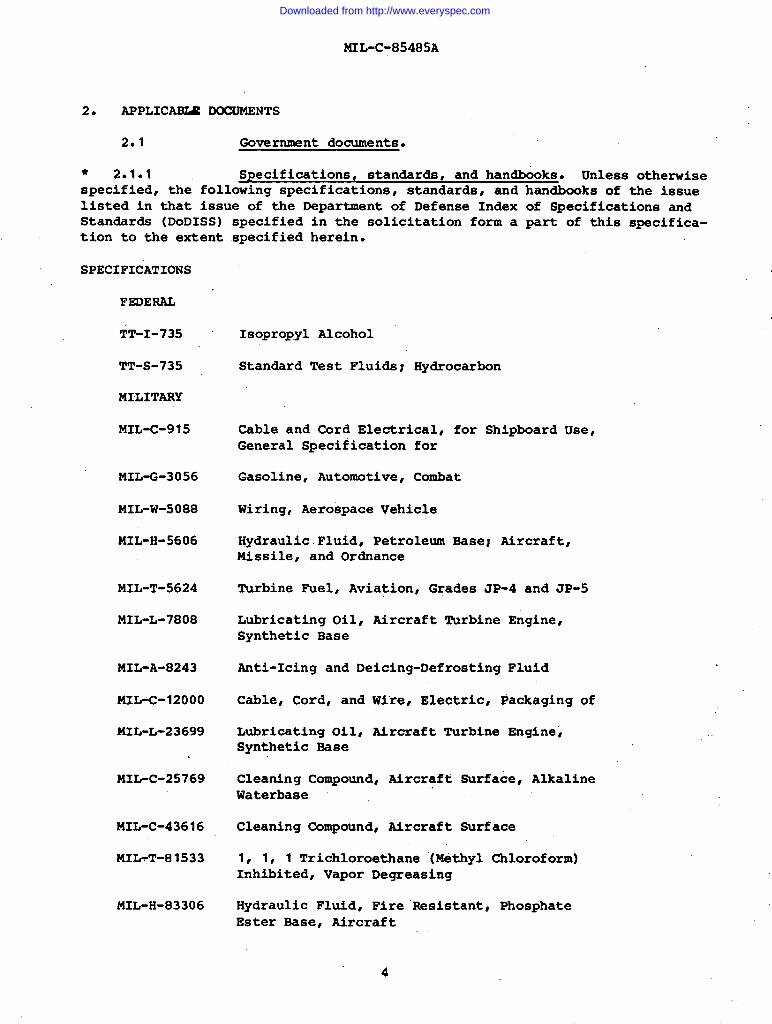
2. APPLIC~ DOCUMENTS
2*1 Government documents.
● 2*1*1 Specifications, standards, and handbooks. Unless otherwisespecified, the following specifications, standards, andlisted in that issue of the Department of Defense IndexStandards (DODISS)tion to the extent
specified in the solicitation form aspecified herein.
handbooks of the issueof Specifications andpart of this specifica-
SPECIFICATIONS
FEDERAL
‘TT-I-735
TT-S-735
MILITARY
MIL-C-915
MIL-G-3056
MIL-w-5088
MIL-H-5606
MIL-T-5624
MIL-L-7808
MIL-A-8243
MIL-C-12000
MIL-L-23699
MIL-C-25769
MIL-C-43616
MIL-T-81533
MIL-H-83306
Isopropyl Alcohol
Standard Test Fluids; Hydrocarbon
Cable and Cord Electrical, for Shipboard Use,General Specification for
Gasoline, Automotive, Combat
Wiring, Aerospace Vehicle
Hydraulic.Fluid, Petroleum Base; Aircraft,Missile, and Ordnance
Turbine Fuel, Aviation, Grades JP-4 and JP-5
Lubricating Oil, Aircraft Turbine Engine,Synthetic Base
Anti-Icing and Deicing-Defrosting Fluid
Cable, Cord, and Wire, Electric, Packaging of
Lubricating Oilv Aircraft Turbine Engine8Synthetic Base
Cleaning Compound, Aircraft Surface, AlkalineWaterbase
Cleaning Compound, fircraft Surface
1, 1, 1 Trichloroethane (Methyl Chloroform)Inhibited, Vapor Decreasing
Hydraulic Fluid, Fire Resistant, PhosphateEster Base, Aircraft
4
I
Downloaded from http://www.everyspec.com

STANDARDS
FEDERAL
FED-STD-228
MILITARY
MIL-STD-104
MIL-STD-105
MIL-STD-109
MIL-STD-129
MIL-STD-681
SUPPLEMENT
MIL-C-85485A
Cable and Wire, Insulated; Methods of Testing
Limits for Electrical Insulation COIOr
Sampling Procedures and Tables for Inspectionby Attributes
Quality Assurance Terms and Definitions
Marking for Shipment and Storage
Identification Coding and Application ofHook Up and Lead Wire
See Supplement 1 for list of applicable specification sheets.
2*1*2 Other Government documents, drawings, and publications. Thefollowing other Government documents, drawings, and publications form a part ofthis specification to the extent specified herein.
PUBLICATIONS
Defense Logi sties Agency Handbooks
H4-1 Federal Supply Code
H4-2 Federal Supply Code
for
for
Manufacturers
Manufacturers
Part 1, Name to dode
Part 2, Code to Name
(Copies of specifications, standards, drawings, and publications required bymanufacturers .in connection with specific acquisition funct$o,ns should be obtainedfrom the acquiring activity or as directed by the contracting officer.)
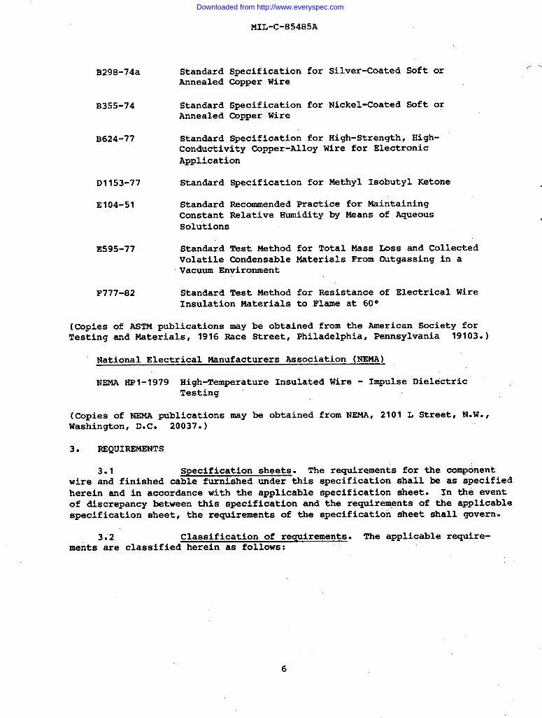
● 2.2 Other publications. The following documents form a part ofthis specification to the extent specified herein. The issues of,the documentswhich are indicated as DoD adopted shall be the issue listed in the currentDoDISS and the supplement thereto, if applicable.
American society for Testing and Materials (ASTM)
B33-78 Standard Specification for Tinned Soft orAnnealed Copper Wire for Electrical PUrpOS43S
B63-49 (1975) Standard Test Method for Resistivity of MetallicallyConducting Resistance and Contact Materials
5
..
I
I
Downloaded from http://www.everyspec.com
MIL-C-85485A
B298-74a StandardAnnealed
B355-74 StandardAnnealed
B624-77 Standard
Specification for Silver-Coated Soft orCopper Wire
Specification for Nickel-Coated Soft orCopper Wire
Specification for High-Strength, High-Conductivity Copper-Alloy Wire for ElectronicApplication
D1153-77 Standard Specification for Methyl Isobutyl Ketone
E104-51 Standard Recommended Practice for MaintainingConstant Relative Humidity by MeansSolutions
E595-77 Standard Test Method for Total MassVolatile Condensable Naterials FromVacuum Environment
F777-82 Standard Test Method for Resistance
of Aqueous
Loss and CollectedOutgassing in a
of Electrical WireInsulation Materials to Flame at 60°
(Copies of ASTM publications may be obtained from the American Society forTesting and Materials, 1916 Race Street, Philadelphia, Pennsylvania 19103.)
National Electrical Manufacturers Association (NEMA)
NEMA HP1-1979 High-Temperature Insulated Wire - Impulse DielectricTesting
(Copies of NEMA publications may be obtained from NEMA, 2101 L Street, N.W.,Washington, D.C. 20037. )
3. REQUIREMENTS
3.1 Specification sheets. The requirements for the componentwire and finished cable furnished under this specification shall be as specifiedherein and in accordance with the applicable specification sheet. In the eventof discrepancy between this specification and the requirements of the applicablespecification sheet, “the requirements of the specification sheet shall govern.
3*2 Classification of requirements. The applicable, require-ments are classified herein as follows:
Downloaded from http://www.everyspec.com
MIL-C-85485A
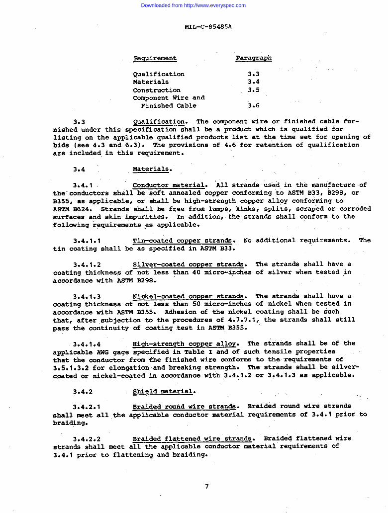
mquirefnent Paragraph
Qualification 3.3Materials 3*4Construction 3*5Component Wire and
Finished -ble 3.6
3.3 ~alification. The component wire or finished cable fur-nished under this specification shall be a product which is qualified forlisting on the applicable ~alified products list at the time set for opening ofbids (see 4.3 and 6.3). The provisions of 4.6 for retention of qualificationare included in this requirement.
3.4 Materials.
3*4.1 Conductor material. ‘All strands us’edin Ae manufacture oftheconductors shall be soft annealed copper conforming to ASTM B33, B298, orB355, as applicable, or shall be high-strength copper alloy conforming toASTM s624. Strands shall be free from lumps, kinks, splits, scraped “or corrodedsurfaces and skin impurities. In addition,. the strands shall conform to thefollowing requirements as applicable.
3.4.1*I Tin-coated COPPer strands. Notin coating shall be as specified in ASTM B33.
3.4.1.2 Silver-coated copper strands.coating thickness of not less than 40 micro-ipchesaccordance with ASTM B298.
3.4.1*3 Nickel-coated copper strands.coating thickness of not less than 50 micro-inchesaccordance with ASTM B355. Adhesion of the nickel
additional requirements. The
I
The strands shall have aof silver when tested in
The strands shall have aof nickel when tested incoating shall be such
that, after .subjection to the procedures of 4.7.7.1, the strands shall stillpass the continuity of coating test in ASTM B355.
3.4.1.4 High-strength copper alloy. The strands shall be of theapplicable AWG gage specified in Table I and of such tensile propertiesthat the conductor from ~e finished wire conforms to the-requirements of3.5.1.3.2 for elongation and breaking strength. The strands shall be silver-c~ted or nickel-coated in accordance with .3.4.1.2 or 3.4.1.3 as applicable.
3.4.2 Shield nvaterial.
3.4.2.1 Braided round wire strands. Braided round wire strandsshall meet all ,the applicable conductor mterial requirements of 3.4.1 prior tobraid+ng.
3.4.2.2 Braided flattened wire”strands. Braided flattened wirestrands sh”allmeet all the applicable conductor material requirements of3.4.1 prior to flattening and braiding.
7
Downloaded from http://www.everyspec.com
MIL-C-85485A
3*4.3 Insulation material.materials shall be in accordance with theshall meet all applicable requirements ofcation sheet.
All insulating and filter layerapplicable specification sheet andTable III and the applicable specifi-
3.5 Construction. Construction of thefinished cable shall be as specified herein and in thesheet.
3.5*1 Conductor.
3.5*1.1 Strandinq.
component wire andapplicable specification
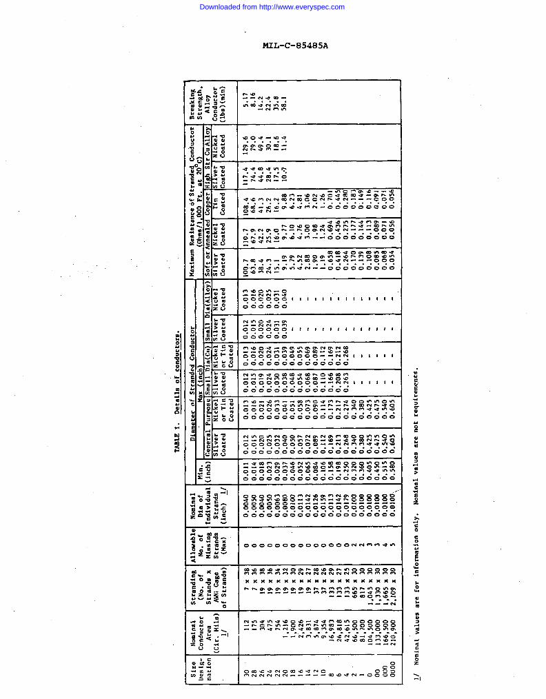
3.591.1.1 Concentric-lay stranding. The conductors of wire sizes 30through 10 shall be concentric-lay conductors constructed as specified in Table 1.Concentric-lay shall be interpreted to be a central strand surrounded by one ormore layers of helically wound strands. It is optional for the direction of layof the successive layers to be alternately reversed (true concentric lay) or tobe in the same direction (unidirectional lay). The strands shall be assembledin a geometric arrangement of concentric layers, so as to produce a smooth anduniform conductor, circular in cross-section and free of any crossovers, highstrands, or other irregularities. The direction of lay of the individualstrands in the outer layer of the concentrically stranded conductors shall beleft hand. The length of lay of the outer layer shall not be less than 8 normore than 16 times the maximum conductorspecification sheet.** 3.5.1.2 Splices. Splices inbe butt brazed. There shall not be morelay lengths of a stranded concentric-layconductor be spliced at one point.
3.5.1.3 Conductor elongation
diameter as specified in the applicable
individual strands or members shallthan one strand-splice in any twoconductor. In no case shall the whole
and breaking strength.
3.5.1.3.1 Soft or annealed copper. The individual strands removedfrom component wires with soft or annealed copper conductors, wire sizes 20and larger, or the whole soft or annealed copper conductor removed from com-ponent wire, sizes 22 and smaller,. shall have the following minimum elongationwhen tested in accordance with 4.7.6.1:
..,,-
Sizes 24 and smaller - 6 percent (minimum)Sizes 22 and larger - 10 percent (minimum)
There shall be no breaking strength requirements for soft or annealed copperconductors.
3.5.1.3.2 High-strength copper alloy. The whole conductor removedfrom component wires with high-strength copper alloy conductors shall exhibitelongation of 6 percent, minimum’, and a breaking strength conforming with TableI, when tested.in accordance with 4.7.6.2.
I
8
L
Downloaded from http://www.everyspec.com
Nominal
Conductor
Area
:ir.
Mlls)
~1
——
TABLE
1.Detailsof
conductors.
Strand@
(No.
ofStrands
xAW
Gage
IfStrands]
1Min.
inch)
Diameter
Of u
Itrund
m lmall
- ,llver
:oated
IConductor
iaximum
Resistance
ofStranded.
mduct
ox
* :oated
129.6
79.0
49..4
30.1
18,6
11.4
Breaking
Strength,
Al10Y
:onductor
lbs)(min)
Size
)esig-
mtion
,llauable
No.of
Missing
Strands
(f4ax)
o 0 0 0 0 0 o“ o 0 0 0 0 0 0 2 2 3 3 4 5
Nominal
Diaof
:ndividual
Strands
;inch)~/
- G :oated
Mmaf1
Inealea
Iickel
:oated
DOFt.
- :oated
It20C
m ~ oated
I m m jrTtr
:oatet
B(A11oY)
~ :oated
- ‘ur
os
c._
& orTin
Coated
- .eneral
- ~llver
:oated
30 28 26 24 22 20 18 16 14 12 10 8 6 4 2 1 0
112
175
304
4?5
754
1,216
1,900
2’,426
3*831
5,074
9,354
16,983
26,818
42,615
66,500
81,700
104,500
133,000
166,500
210,900
7x38
7x36
19X38
]9X36
19x34
19X32
19x30
19X29
19X27
37X28
31X26
133X29
133X27
133X25
665’X30
817X30
1,045
x30
1,330
x30
1,665
X30
2,109
X30
0.0040
0.0050
0.0040
0.0050
0.0063
0.0080
0.0100
0.0113
0.0142
0.0126
0.0159
0.0113
0.0142
0.0179
0.0100
0.0100
0.0100
0.0100
0,0100
0.0100,,
0.01
10.014
0.018
0.02
30.02
90.03
70.04
60.05
20.06
50.08
fI0.106
0.158
0.198
o+250
0.32
00.36
00.40
50.45
00.515
0.580
0.012
0.015
0.02
(70,02
50.03
20.04
00.05
00.05
70.072
0.08
90.112
0.169
0.213
0.26
80.34
00.38
00.Ii25
0.475
0.54
00.60
5
0.013
0.016
0.02
10.02
60.03
30.04
10.05
10.05
80.073
0.09
00.114
0.173
0.21
70.274
0.3.40
0.38
00.42
50..475
0.54
00.60
5
0.012
0.015
0.019
0.024
0.030
0.038
0.048
0.054
0.068
0.087
0.110
0.166
0.208
0.263
0.013
0.016
0.020
0.024
0.031
0.039
0.049
0.055
0.069
0.089
0.112
0.169
0.212
0.268
3.012
?.015
D.020
o.02h
D.031
D.039 .
0.013
0.016
0.020
0.025
0.031
0.0.40
00,7
63.8
38.4
24.3
15,1 9.19
5.79
4.52
2.88 1.90
1.19
0.658
0.418
0.264
0.170
0.139
0.108
0.085
o,06a
0.054
10.7
67.9
42.2
25.9
16.0 9.71
6.10
4.76 3.00
1.98
1.24
0.694
0.436
0,275
0,177
0.144
0.11?
0.085
0.071
o.05t
08.4
68.6
41.3
26.2
16.2 9.886.23
4.81 3.06
2.02 1.26
0.701
0.44!
o.2tu
0.18’
0.14<
0.11
(0.091
0.07
10.05
1
117.4
74.4
44.8
28.4
17.5
10..7
5.178.16
14.2
22.4
35.8
58.1
00 0[)0
O(J
OO
~/Nominal
values
arefor
information
only.
Nominal
values
arenotrequfrements.
Downloaded from http://www.everyspec.com
MIL-C-85485A
3.5.1.4 Conductor diameter. The diameter of the conductor shall beas specified in Table I. Applicability of the “general purpose” or of the“small diameter’*Table I requirements for maximum conductor diameter shall be asindicated in the specification sheet.
3.5.2 Shield. The shield shall be constructed as specified in theapplicable specification sheet.
● 3.5*3 Insulation. The insulating and filter layers shall beconstructed as specified in the applicable specification sheet. All componentinsulation shali be readily removable by conventional wire stripping deviceswithout damage to the conductor.
3.6 Component wire and finished cable. The component wire andfinished cable shall conform to the requirements of Table III and those ofthe applicable specification sheet. The requirements of 3.6.1 through 3.6.10also apply. Unless otherwise specified, component wire shall conform to allapplicable requirements prior to assembly into the finished cable.
● 3.6*1 Blocking. Adjacent turns or layers of the component wire orcable jacket shall not stick to one another when tested as specified in 4.7.4 atthe temperature specified in the applicable specification sheet.
* 3.6.2 Cabling. The required number of component wires as.speci-fied in the applicable specification sheet shall be cabled together with a lefthand lay. For cables having multiple layers, the outer layer shall be left handand the inner layer or layers may be either right hand or left hand lay. Thelength of the individual component wires shall be not less than 8 times normore than 16 times the diameter of the applicable layer. Fillers and bindersshall be used only ‘as specified in the applicable specification sheet.
● 3.6.3 Color. Unless otherwise specified in the contract orpurchase order, the color of component wire shall be light violet, designated7L. The preferred colors for components in a finished cable shall be lightviolet for component number 1 and light violet with stripe designators forremaining component wires as follows:
Component number 1 2 3 4 5 6 7Color designation 7L 7L6 7L3 7L5 7L2 7L0 7L4
ml solid colors and the colors of all striping shall be in accordance withMIL-STD-104, Class 1, unless otherwise specified. Color striping, if appli-cable, shall conform to MIL-sTD-681 and shall be capable of withstanding thestriping durability test of 4.7.11 for the number of strokesweight specified in the applicable specification sheet.
● 3.6.4 Crosslinking proof test and life cycle.tested in accordance with 4.7.10, there shall be no crackingor jacket and no dielectric breakdown, as applicable.
10
and with the
When samples areof the insulation
lay
by
‘..,
\
Downloaded from http://www.everyspec.com
* 3.6.5all finished cable
MIL-C-85485A
Conductor and shield continuity. One hundred percent ofshall be tested for continuity prior to shipment. There
shall be no indication of discontinuity in any of the component wires orshields.
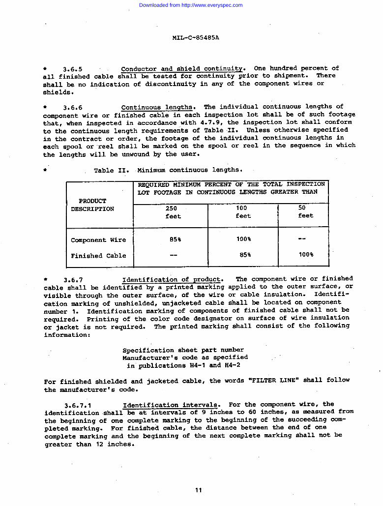
* 3.6.6 continuous lengths. The individual continuous lengths ofcomponent wire or finished cable in each inspection lot shall be of such footagethat, when inspected in accordance with 4.7.9, the inspection lot shall conformto the continuous length requirements of Table II. Unless otherwise specifiedin the contract or order, the footage of the individual continuous lengths ineach spool or reel shall be Mrked on the spool or reel in the sequence in which—the lengths will be unwound by the user.
● Table II. Minimum continuous lengths.
REQUIRED MINIMUM PERCENT OF THE TOTAL INSPECTIONLOT FOOTAGE IN CONTINUOUS LENGTHS GREATER THAN
PRODUCTDESCRIPTION 250 I 100 I 50
feet feet feet
IComponent Wire I 85%I
100% I --Finished Cable -- 85% 100%
● 3.6.7 Identification of product. The component wire or finishedcable shall be identified by a printed marking applied to the outer surface, orvisible through the outer surface, of the wire or cable insulation. Identifi-cation marking of unshielded unjacketed cable shall be located on componentnumber 1. Identification marking of components of finished cable shall not berequired. Printing of the color code designator on surface of wire insulationor jacket is not required. The printed marking shall consist of the followinginformation:
Specification sheet part numberManufacturercs code as specifiedin publications X4-1 and H4-2
For finished shielded and jacketed cable, the words “FILTER LINE” shall followthe manufacturers code.
3.6.7.1 Identification intervals, For the component wire, theidentification shall be at intervals of 9 inches to 60 inches, as measured fromthe beginning of one complete marking to the beginning of the succeeding com-pleted marking. For finished cable, the distance between the end of onecomplete marking and the beginning of the next complete marking shall not begreater than 12 inches.
11
Downloaded from http://www.everyspec.com
MIL-C-85485A
● 3.6.7.2 Identification color. The printing shall be white in color ‘--”in accordance with MIL-STD-104, Class 1. Identification printing shall beapplied with the vertical axes of the printed characters lengthwise of the com-ponent wire or finished cable when the nominal diameter is 0.050 inch orsmaller. The vertical axes of the printed characters may be either crosswise orlengthwise of the component wire or finished cable when the nominal diameterexceeds 0.050 inch. All printed characters shall be complete and legible.
3.6.7.3 Durability of identification. Identification printing,when applied to the outer surface of the component wire or finished cable,where applicable, shall be capable of withstanding the durability testspecified in 4.7.11 for the number of cycles and with the weight specifiedin the applicable specification sheet.
● 3.6.8 Insulation and jacket flaws. When required by the appli-cable specification sheet, one hundred percent of the component wire andfinished cable shall pass the spark test of 4.7.17.1 or the impulse dielectrictest of 4.7.17.2, Testing of finished component wire or cable shall be per-formed during the final winding on shipment spools or reels. Component wireintended for finished cable shall be tested prior to cabling.
3.6.9 Workmanship. All details of workmanship shall be in accor-dance with high grade wire and cable manufacturing practice. The insulationshall be free of crackst splits, irregularities, and imbedded foreign material.
* 3.6-10 Wrap test. When component wires are tested in accordancewith 4.7.29, there shall be no cracking of insulation.●
* 3.6.11 Jacket resistivity. “When tested in accordance with 4.7.1,the jacket resistivity for conductive jackets shall be 150 ohm-cm, maximum.
● 3.6.12 Low temperature (cold bend). When samples are tested inaccordance with 4.7.19, there shall be no cracking of the insulation or jacketand no dielectric breakdmn.
4.0 QUALITY ASSURANCE PROVISIONS
4.1 Responsibility for inspection. Unless otherwise specifiedin the contract or purchase order~ the supplier is responsible for the perfor-mance of all inspection requirements as specified herein. --”Exceptas otherwisespecified in the contract or order, the supplier may use his own or any other”””facilities suitable for the performance of the inspection requirements speci-fied herein, unless disapproved by the Government. The Government reservesthe right to perforh any of the inspections set forth in the specificationwhere such inspections are deemed necessary to assure that ,supplies and ser-vices conform to prescribed requirements.
I
I
I
I
4.2. Classification of inspections. The examinations and testsof component wire and finished cable under this specification shall be dividedinto the following classifications:
12
Downloaded from http://www.everyspec.com
-. .
MIL-c-85485A
Classification Paragraph
Qualification inspection 4.3Quality conformance inspection 4.4Process control inspection 4*5Periodic qualification re-evaluation 4.6
* 4.3 ~alification inspection. Qualification inspection shallconsist of the examination and tests listed in Tables III and IV of this speci-fication as applicable to the component wire or finished cable. Qualificationapproval for finished cable must be obtained both for the components and forthe finished construction.
I* 4.3.1 Sampling for qualification inspection. Except as providedin 4.3.1.1, a component wire or finished cable sample of the required lengthshall be tested for each range of component wire or finished cable sizes forwhich qualification is desired. The sample may be any size of component wireor finished cable within the size range specified below. Within each sizerange for which qualification is desired for shielded, jacketed cable, both asingle-conductor and a multiple-conductor finished cable sample must be testedif they fall within that size range.strand used in the manufacture of thewith the finished wire sample.
Component WireSize Range
24 and smiler22 through 1816 and larger
Ten linear feet of the coatedfinished wire sample shall be
conductorsubmitted
IRequired Lengthof Sample (Feet)
200
200
200
Finished Cable Size Range Required LengthNominal Overall Diameter (Inch) of Sample (Feet)
< 0.100 100
> 0.100 and <0.150 100> 0.150 and <0.225 100
> 0.225 100
* 4.3.101 Optional qualification samples. In cases where two ormore specification sheets cover component wire or finished cable identical inmaterials and construction except for conductor and/or shield material (i.e.,the specified conductor’or shield may be tin-coated copper, silver-coated highstrength copper alloy or as specified in the applictile specification sheet),the component wire or finished cable sample in accordance with 4.3.1 mayqualify any one of the specification sheets. For those sheets so qualified bysimilarity, a conductor and/or strand shall be tested in accordance with theapplicable conductor and/or strand requirements of Table 111. One conductorand/or strand shall be tested for each size range specified in 4.3.1.Approval of the qualification sample shall also qualify the same componentwire or finished cable size range or ranges in each of the other specificationsheets. Ten linear feet of the conductor strand and shield strand applicable
13
Downloaded from http://www.everyspec.com
MIL-C-85485A
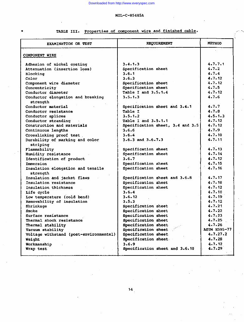
* TASLE III. Properties of component wire and finished cable. ,,.......,
L
EXAMINATION OR TEST REQUIREMENT METHOD
COMPONENT WIRE
Adhesion of nickel coating 3.4.1.3 4.7.7.1Attenuation (insertion loss) Specification sheet 4.7.2Blocking 3.6.1 4.7.4Color 3.6.3 4.7.12Component wire diameter Specification sheet 4.7.12Concentricity Specification sheet 4.7.5Conductor .diameter Table I and 3.5.1.4 4.7.12Conductor elongation and breaking 3.5.1.3 4.7.6
strengthConductor material Specification sheet and 3.4.1 4.7.7Conductor resistance Table I 4.7.8Conductor splices 3.5.1.2 4.5.1.3Conductor stranding Table I and 3.5.1.1 4.7.12Construction and materials Specification sheet, 3.4 and 3.5 4.7.12Continuous lengths 3.6.6 4.7.9Crosslinking proof test 3.6.4 4.7.10Durability of marking and color 3.6.3 and 3.6.7.3 4.7.11
stripingFlammability Specification sheet 4.7:13Humidity resistance Specification sheet 4.7.14Identification of product 3.6.7 4.7.12Immersion Specification sheet 4.7.15Insulation elongation and tensile Specification sheet 4.7.16strength
Insulation and jacket flaws Specification sheet and 3.6.8 4.7.17Insulation resistance Specification sheet 4.7.18Insulation thickness Specification sheet 4.7.12Life cycle 3.6.4 4.7.10LOW temperature (cold bend) 3.6.12 4.7.19Removability of insulation 3.5.3 4.7.12Shrinkage Specification sheet 4.7.21Smoke Specification sheet 4.7.22Surface resistance Specification sheet 4.7.23Thermal shock resistance” Specification sheet 4.7.25Thermal stability Specification sheet .. 4.7.26Vacuum stability Specification sheet ““ ASTM E595-77Voltage withstand (post-environmental) Specification sheet 4.7.27.2Weight Specification sheet 4.7.28Workmanship 3.6.9 4.7.12Wrap test Specification sheet and 3.6.10 4.7.29
14
Downloaded from http://www.everyspec.com
MIL-C-85485A
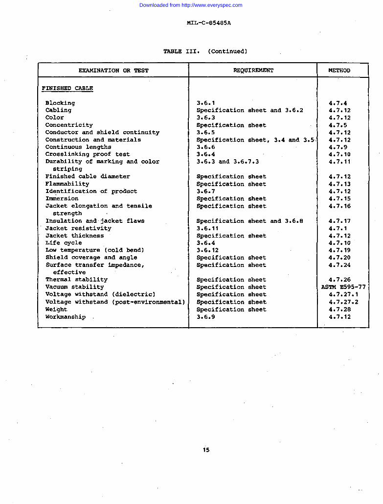
TABLE III. (Continued)
EXAMINATION OR TEST REQUIREMENT METHOD
FINISHED CABLE
Blocking 3.6.1 4.7*4Cabling Specification sheet and 3.6.2 4.7.12Co”lor 3.6.3 4.7.12Concentricity Specification sheet 4.7.5Conductor and shield continuity 3.6.5 4.7.12Construction and materials Specification sheet, 3.4 and 3.5. 4.7.12Continuous lengths 3.6.6 4.7.9Crosslinking proof test 3.6.4 4*7.1ODurability of marking and color 3.6.3 and 3.6.7.3 4.7.11
stripingFinished cable diameter Specification sheet 4.7.12Flammability Specification sheet 4.7.13Identification of product 3.6.7 4.7.12I&ersion Specification sheet 4.7.15Jacket elongation and tensile Specification sheet 4.7.16strength
Insulation and jacket flaws Specification sheet and 3.6.8 4.7.17Jacket resistivity 3.6.11 4.7.1Jacket thickness Specification sheet 4.7.12Life cycle 3.6.4 4.7.10Low temperature ‘(coldbend) 3.6.12 4.7.19Shield coverage and angle Specification sheet 4.7.20Surface transfer impedance, Specification sheet 4.7.24effective
Thermal stability Specification sheet 4.7.26Vacuum stability Specification sheet ASTM E595-77Voltage withstand (dielectric) Specification sheet 4.7.27.1Voltage withstand (post-environmental) Specification sheet 4.7.27.2Weight Specification sheet 4.7.28Workmanship . 3.6.9 4.7.12
,,
1 5
Downloaded from http://www.everyspec.com
MIL-C-85485A
to the same wire or cable size range as the finished wire or cableshall be submitted when qualification by similarity is requested.
samples(Note: For
purposes of determining identity of construction in specification sheets underthis provision, small differences in specified component wire or finishedcable diameter or weight which are due to differences in the specified conduc-tor or shield shall not be considered as constituting differences in construc-tion of the component wire or finished cable.)
* 4.3.2 Forwarding of qualification samples. Samples and themanufacturer’s certified test reports shall be forwarded to the testing labora-tory designated in the letter of authorization from the activity responsible forqualification (see 6.3), plainly identified by securely attached, durable tagsmarked with the following information:
Sample for qualification testCABXIE,ELECTRIC, FILTER LINE,
RADIO FREQUENCY ABSORPTIVESpecification sheet part numberManufacturer’s name and code number
(Publications H4-I and H4-2)Manufacturer’s part numberComprehensive description and manufacturer’s name
and’formulation number of the base materials fromwhich the product is made. (This information willnot be divulged by the Government.)
Place and date of manufacture of sampleSubmitted by (name) (date) for qualification tests
in accordance with the requirements of MIL-C-85485Aunder authorization (reference authorizing letter).
The tags or spools must be stamped by the government inspector as represent-ative samples of the manufacturer’s normal production capability. Samplessubmitted without the stamp will not be accepted.
4.4 $)uality conformance inspection. Quality conformance in-spection shall consist of the examinations and tests listed in Table IV anddescribed under “Test Methodsct (4.7). Quality conformance inspection shallbe performed on every lot of component wire or finished cable procuredunder this specification.
..-”
4.4.1 Sampling for quality conformance inspection. MIL-STD-109shall apply for definitions of inspection terms used herein. For purposesof this specification, the following shall apply.
4.4*1.1 Lot . The inspection lot shall include all component wire orfinished cable of on=~rt number subjected to inspection at one time.
size forcable as
4.4.1.2 Unit of product. The unit of product for determining lotsampling shall be one continuous length of component wire or finishedoffered for inspection.
16
Downloaded from http://www.everyspec.com
MIL-c-85485A
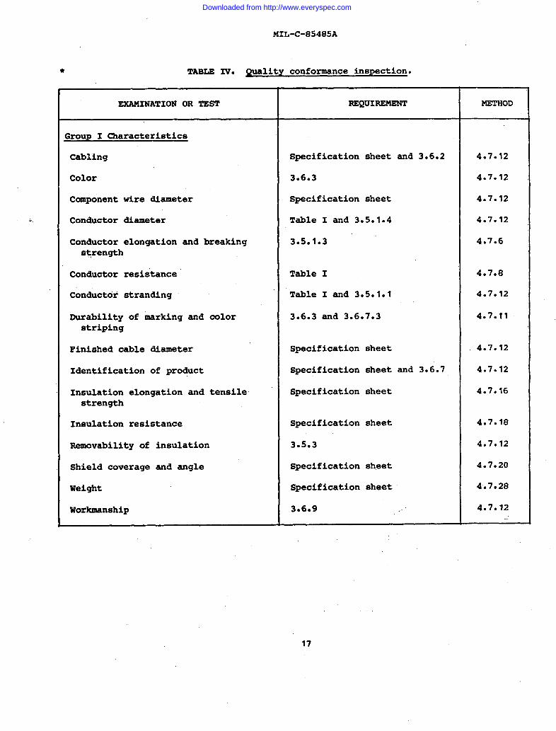
● TABLE IV. Quality conformance inspection.
,.
EXAMINATIONORTEST lUZQUI~ METHOD I
Group I Characteristics
Cabling Specification sheet and 3.6.2 4.7.12
Color 3.6.3 4.7.12
Component wire diameter Specification sheet 4.7.12
Conductor diameter Table I and 3.5.1.4 4.7.12
Conductor elongation and breaking 3.5.193 4.7.6strength
Conductor resistance’ Table I 4.7.8
Conductor stranding Table I and 3.5.1.1 4.7.12
Curability of marking and color 3.6.3 and 3.6.7.3 4.7011striping
Finished cable diameter Specification sheet 4.7.12
Identification of product Specification sheet and 3.6.7 4.7.12
Insulation elongation and tensile Specification sheet 4.7.16strength
Insulation resistance Specification sheet 4.7.18
Removability of insulation 3.5.3 4.7.12
Shield coverage and angle Specification sheet 4.7.20
Weight Specification sheet 4.7.28
Workmanship 3.6.9 4.7.12
I
I
1 7
Downloaded from http://www.everyspec.com
MIL-C-85485A
“L”_ti5 .L V \ L-VU GLIIU=U J
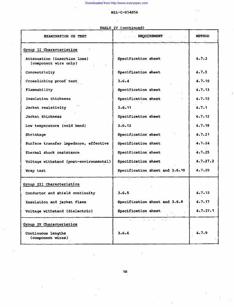
EXAMINATION OR TEST REQUIREMENT METHOD
Group II Characteristics ~~
Attenuation (insertion loss) Specification sheet 4..7.2(component wire only)
Concentricity Specification sheet 4.7.5
Crosslinking proof test 3.6.4 4*7*1O
Flammability Specification sheet 4.7.13
Insulation thickness Specification sheet 4.7.12
Jacket resistivity 3.6.11 4.7.1
Jacket thickness Specification sheet 4.7.12
LOw temperature (cold bend) 3.’6.12 4.7.19
Shrinkage Specification”sheet 4.7.21
Surface transfer impedance, effective Specification sheet 4.7.24
Thermal shock resistance Specification sheet 4.7.25
Voltage withstand (post-environmental) Specification sheet 4.7.27.2
Wrap test Specification sheet and 3.6.10 4.7.29
Group III Characteristics
Conductor and shield continuity 3.6.5 4.7.12
Insulation and jacket flaws Specification sheet and 3.6.8 4.7.,17
Voltage withstand (dielectric) Specification sheet 4.7,27.1
Group IV Characteristics
Continuous lengths 3.6.6 4.7.9(component wires)
18
I
Downloaded from http://www.everyspec.com
MIL-C-85485A
404.1.3 Sample unit (Groups I and II tests). The sample unit forGroups I and II tests, except for the Group I insulation resistance test, shall—consist of a single piece of component wire or finished cable chosen at randomfrom the inspection lot and of sufficient length to permit all applicable exami-nations and tests. Unless otherwise specified, the length of the sample unitfor Group I tests of Table IV, other than insulation resistance, shall be 20feet and the length of the sample unit for Group II tests shall be 25 feet. Notmore than one sample unit for each group of tests shall be taken from a singleunit of product.
4.4*1.3.1 Sample unit for insulation resistance te~t (Group I). Thesample unit for the Group I insulation resistance test shall be a specimen atleast 26 feet in length selected at random from component wire which has passedthe Group III insulation flaws test. It is optional whether the specimen istested on the reel or removed from the reel for the test, provided the lengthof the specimen can be determined.
4.4.1.4 Inspection levels and acceptable quality levels (AQL)(Groups I an II tests). For Group I characteristics, including the insulationresistance test, the inspection level shall be S-2 and the AQL shall be 6.5percent defective units in accordance with MIL-STD-105. For Group II charac-teristics, the inspection level shall be S-3 and the AQL shall be 1.5 percentdefective units.
* 4.4.1.5 Sampling and acceptance for the Group III tests. Thesample for the Group III tests shall be 100 percent of the component wire orfinished cable and every length of the wire or cable shall be subjected fullyto these tests. Insulation breakdowns resulting from the test and ends orportions not subjected to the test shall be cut out of the component wire orfinished cable.
4.4.1.6 Sampling and acceptability for Group IV examination. Theinspection level and acceptable quality level for continuous lengths examina-tion shall be as required by 4.7.9.
4.4.2 Nonconforming inspection lots. Disposition of inspectionlots found unacceptable under initial quality conformance inspection shall bein accordance with MIL-STD-105.
4“.5 Process control inspection. This inspection comprisestests and examinations of”such a nature that they cannot be performed on thecomponent wire or finished cable as submitted for inspection and thereforemust be conducted at the most appropriate stage of the manufacturing opera-tions. The process control ”tests shall consist of the tests listed”in Table V.Process control inspection shall be performed on every lot of component wireor finished cable procured under this specification.
19
Downloaded from http://www.everyspec.com
“., . . .
MIL-C-85485A
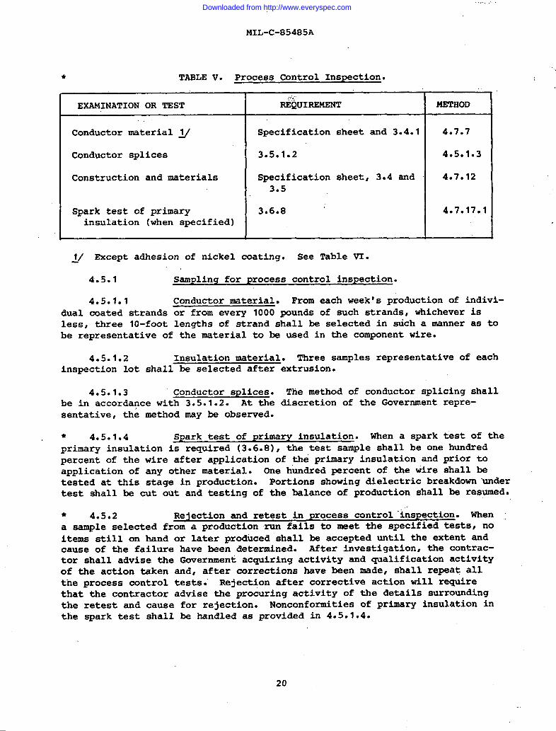
● TABLE V. Process Control Inspection....
,-,,,,,EXAMINATION OR TEST
,.REQUIREMENT METHOD
Conductor material ~/ Specification sheet and 3.4.1 4.7*7
Conductor splices 3.5.1.2 4.5.1.3
Construction and materials Specification sheet, 3.4 and 4.7.123.5
Spark test of primary 3.6.8 ~ 4.7.17.1insulation (when specified)
~/ Except adhesion of nickel coating. See Table VI.
4.5.1 Sampling for process control inspection.
4.5.1.1 Conductor material. From each week’s production of indivi-. . .
dual coated strands or from every 1000 pounds of such strands, whichever 1sless, three 10-foot lengths of strand shall be selected in such a manner as tobe representative of the material to be used in the component wire.
4.5.1.2 Insulation material. Three samples representative of eachinspection lot shall be selected after
4.5.1.3 Conductor splices.be in accordance with 3.5.1.2. At thesentative, the method may be observed.
extrusion.
The method of conductor splicing shalldiscretion of the Government repre-
* 4.5.1.4 Spark test of primary insulation. When a spark test of theprimary insulation is required (3.6.8), the test sample shall be one hundredpercent of the wire after application of the primary insulation and prior toapplication of any other material. One hundred percent of the wire shall betested at this stage in production. Portions showing dielectric breakdown “undertest shall be cut out and testing of the balance of production shall be resumed.
* 4.5.2 Rejection and retest in process control ‘inspection. Whena sample selected from a production run fails to meet the specified testsr noitems still on hand or later produced shall be accepted until the extent andcause of the failure have been determined. After investigation, the contrac-tor shall advise the Government acquiring activity and qualification activityof the action taken and, after corrections have been made, shall repeat allthe process control tests. Rejection after corrective action will requirethat the contractor advise the procuring activity of the details surroundingthe retest and cause for rejection. Nonconformities of primary insulation inthe spark test shall be handled as provided in 4.5.1.4.
I
20
Downloaded from http://www.everyspec.com
MIL-C-85485A
4.5.2.1 Effect of process control failure on quality conformancetesting. Quality conformance testing may be continued during the investigationof the failure of a process control sample8 but final acceptance of the materialshall not be made until it is detetined that the lot meets all the Processcontrol requirements and quality conformance requirements of the specification.
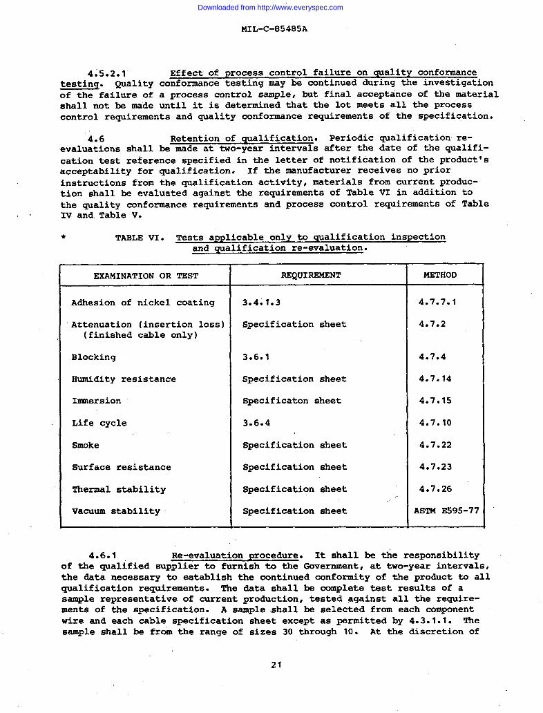
4.6 Retention of qualification. Periodic qualification re-evaluations shall be made at two-year intervals after the date of the qualifi-cation test reference specified in the letter of notification of the product’sacceptability for qualification. If the manufacturer receives no priorinstructions from the qualification activity, materials from current produc-tion shall be evaluated against the requirements of Table VI in addition tothe quality conformance requirements and process control requirements of Table
. . IV and.Table V.
TAELE VI. Tests applicable only to qualification inspectionand qualification re-evaluation.
EXAMINATION OR TEST REQUIREMENT METHOD
Adhesion of nickel coating 3.401.3 4.7.7.1
Attenuation (insertion loss) Specification sheet 4.7.2(finished cable only)
Blocking 3.6.1 4.7.4
Humidity resistance Specification sheet 4.7.14
Immersion Specification sheet 4.7.15
Life cycle 3.6.4 4.7.10
Smoke Specification sheet 4.7.22
Surface resistance Specification sheet 4.7.23
Thermal stability Specification sheet 4.7.26.,...
Vacuum stability Specification sheet ASTME595-77
4.6.1 Re-evaluation procedure. It shall be the responsibilityof the qualified supplier to furnish to the Government, at two-year intervals~the data necessary to establish the continued conformity of the product to allqualification requirements. The data shall be complete test results of asample representative of current production, tested against all the require-ments of the specification. A sample shall be selected from each componentwire and each cable specification sheet except as permitted by 4.3.1.1. Thesample shall be from the range of sizes 30 through 10. At the discretion of
21
I
Downloaded from http://www.everyspec.com

MIL-C-85485A
the qualifying activity, test recorw from current production E@Y be accepted ~ ~:/,.-.,
for the re-evaluation to the extent they are available and samples fromcurrent production need be subjected to only the tests for which no productiontest records are available. The samples, each 200 feet long, and test reportswith supporting data shall be submitted to the qualifying activity as speci-fied in 4.3.2. IUl conductor and strand samples shall be 10 feet long. Ifa failure occurs, no product represented by the sample nor any other productmanufactured with the same materials and processes, which has not already beensubmitted for quality conformance inspection, shall be offered for acceptanceuntil the cause for failure has been determined and concurred in by thequalifying activity as not affecting the ability of the product to pass quali-fication inspection requirements. In the event the date for re-evaluation haspassed, the supplier shall still be eligible for contract award, but finalacceptance of product from such a supplier is contingent upon his productmeeting all the qualifying requirements’ of the specification.
4.7 Test methods.
● 4.7.1 Jacket resistivity.
* 4.7.1.1 Specimen preparation. A six-inch specimen of conductivejacket material shall be prepared by removing the jacket from the cable. Thejacket may be pulled from the end of the cable as a tube, or it may be slitlongitudinally-and removed.
* 4.7.1.2 Measurement procedure.material shall be determined in accordanceabove.
4.7.2 Attenuation (insertion
TheWith
resistivity of the jacket
ASTM B63 except as described
loss) ●
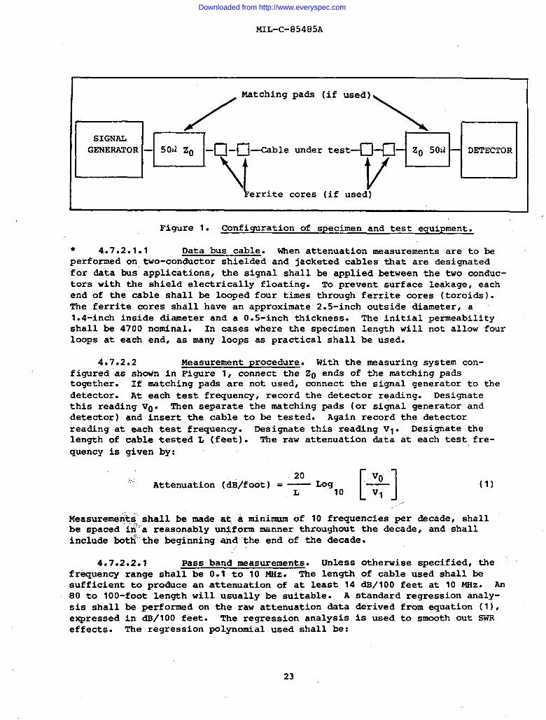
4.7c2el Configuration. me configuration of specimen and testequipment for determining attenuation is shown in Figure 1. Matching padsshall be used, when specified, to reduce measurement SWR. The cable undertest and the matching pads, if required, are connected between a signalgenerator and a detector. The matching pads should have a characteristicimpedance of so t 2 ohms on one end, and Z. k 10% on the other end~ where20 is the characteristic impedance of the cable configuration under test, asdetermined by MIL-C-915. Unless otherwise specified, single conductor cablesshall be measured between conductor and shield and cables of two or more con-ductors shall be tested between one conductor, and all other shields and con- ‘“ductors grounded together at both ends of &e cable specimen.
.
22
Downloaded from http://www.everyspec.com
MIL-c-85485A
cSIGNALGENERATOR
/
Matching
n- ‘O” z“ -Ci-cl-ble
\t
pads (if used )
~~m
under test— z“ soil DETECTOR
l?errite cores (if use~)
Figure 1. Confi guration of specixnen and test equipment.
● 4.70201el Data bus cable. When attenuation measurements are to beperformed on two-conductor shielded and jacketed cables that are designatedfor data bus applications, the signal shall be applied between the two conduc-tors with the shield electrically floating. To prevent surface leakage, eachend of the cable shall be looped four times through ferrite cores (toroids).The ferrite cores shall have an approximate 2.5-inch outside diameter, a1.4-inch inside diameter and a O.S-inch “thickness. The initial permeabilityshall be 4700 nominal. In cases where the specimen length will not allow fourloops at each end, as many loops as practical shall be used.
4.7.2.2 Measurement procedure. With the measuring system con-figured as shown in Figure 1, connect the 20 ends of the matching padstogether. If matching pads are not used, connect the signal generator to thedetector. At each test frequency, record the detector reading. Designatethis reading V“. Then separate the ~tching pads (or signal generator anddetector) and insert the cable to be tested. Again record the detectorreading at each test frequency. Designate this reading V1. Designate thelength of cable tested L (feet). The raw attenuation data at each test fre-quency is given by:
20
[ 1..
v“Attenuation (dB/foot) =—Log ‘—
L 10 V1(1)
,.Measuremen>s,shall be made at,a minimum of 10 frequencies per decade, shallbe spaced ’ifi’areasonably -form manner throughout the decade, and shallinclude botfi’the beginning ahd”the end of the decade.
,.
4.7.2.2.1 Pass band measurements. Unless otherwise specified, thefrequency range shall be 0.1 to 10 MHZ. The length of cable used shall besufficient to produce an attenuation of at least 14 dB/100 feet at 10 MHz. An80 to 100-foot length will usually be suitable. A standard regression analy-sis shallexpressedeffects.
be performed on the raw attenuation data derived from equation (11,in dB/100 feet. The regression analysis is used to smooth out SWRThe regression polynomial used shall be:
23
Downloaded from http://www.everyspec.com
MIL-C-85485A
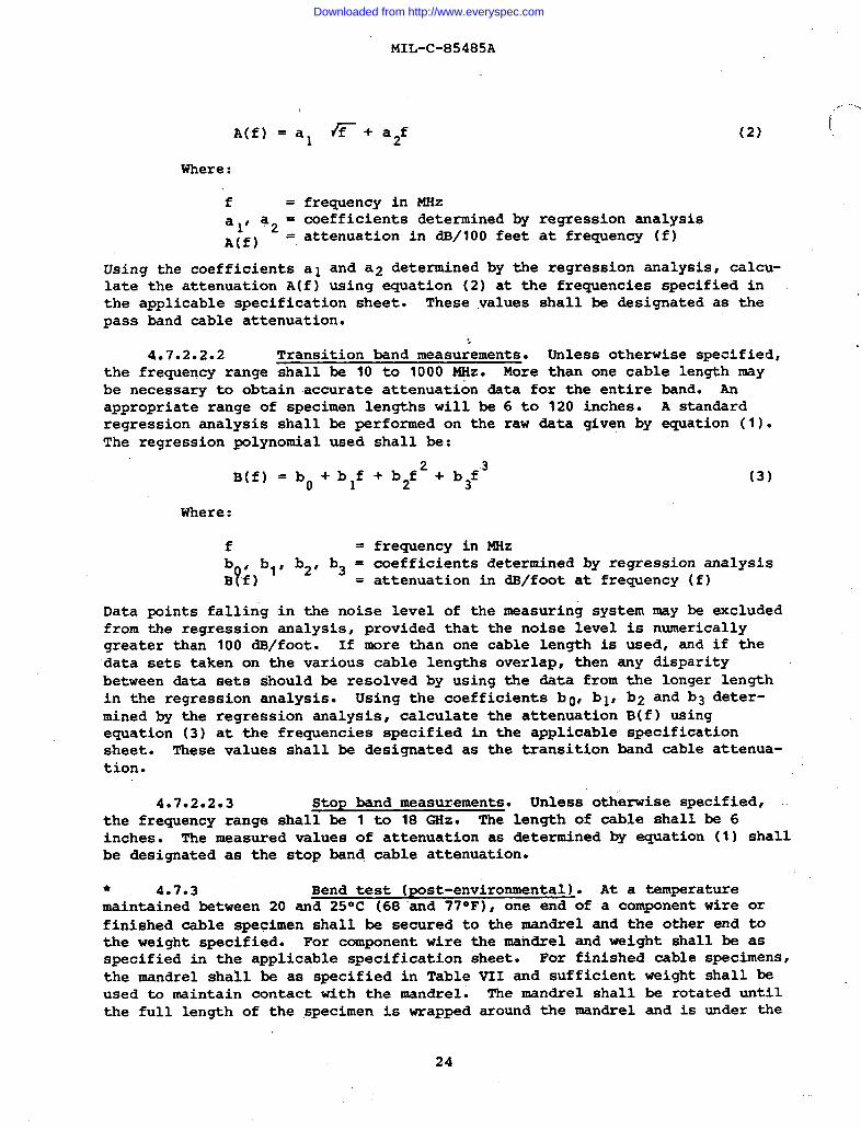
A(f) = al ~+ a2f
Where:
f = frequency inalt a. = coefficients
(2)
MHzdetermined by regression analysis
L
Aif) = attenuation in dB/100 feet at frequency (f)
Using the coefficients al and a2 determined by the regression analysis, calcu-late the attenuation A(f) using equation (2) at the frequencies specified inthe applicable specification sheet. These values shall be designated as thepass band cable attenuation.
‘,
4.7.2.2.2 Transition band measurements. Unless otherwise specified,the frequency range shall be 10 to 1000 MHz. More than one cable length maybe necessary to obtain accurate attenuation data for the entire band. Anappropriate range of specimen lengths will be 6 to 120 inches. A standardregression analysis shall be performed on the raw data given by equation (1).The regression polynomial used shall be:
B(f) = bO +blf + b2f2+ b3f3 (3)
Where:
f = frequency in MHz
:?~)b” b2’ b3= coefficients determined by regression analysis= attenuation in dB/foot at frequency (f)
Data points falling in the noise level of the measuring system may be excludedfrom the regression analysis, provided that the noise level is numericallygreater than 100 dB/foot. If more than one cable length is used, and if thedata sets taken on the various cable lengths overlap, then any disparitybetween data sets should be resolved by using the data from the longer lengthin the regression analysis. Using the coefficients bo, bl, b2 and b3 deter-mined by the regression analysis, calculate the attenuation B(f) usingequation (3) at the frequencies specified in the applicable specificationsheet. These values shall be designated as the transition band cable attenua-tion.
4.7.2.2.3 Stop band measurements. Unless otherwise specified,the frequency range shall be 1 to 18 GHz. The length of cable shall be 6inches. The measured values of attenuation as determined by equation (1) shallbe designated as the stop band cable attenuation.
* 4.7.3 Bend test (POst-environmental). At a temperaturemaintained between 20 and 250c (68 ‘and 77° F), one end of a component wire orfinished cable specimen shall be secured to the mandrel and the other end tothe weight specified. For component wire the mandrel and weight shall be asspecified in the applicable specification sheet. For finished cable specimens,the mandrel shall be as specified in Table VII and sufficient weight shall beused to maintain contact with the mandrel. The mandrel shall be rotated untilthe full length of the specimen is wrapped around the mandrel and is under the
24
I
Downloaded from http://www.everyspec.com
MIL-C-85485A
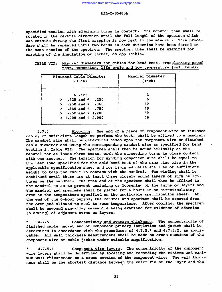
specified tension withrotated in the reversewas outside during thedure shall be repeated
adjoining turns in contact. The mandrel then shall bedirection until the full length of the specimen whichfirst wrapping is now next to the mandrel. This proce-until two bends in each direction have been formed in
the same section of the specimen. The specimen then shall be examined forcracking of the insulation or jacket, as applicable.
TABLE VII. Mandrel diameters for cables for bend test, crosslinking prooftest, immersion, life cycle and low temperature (cold bend).
Finished Cable Diameter(Inch)
< .125> .125 and < .250> .250 and < .360> .360 and < ..750> .750 and < 1.200> 1.200 and < 2.000
Mandrel Diameter(Inch)
3610183048
4*7.4 Blocking. One end of a piece of component wire or finishedcable, of sufficient length to perform the test, shall be affixed to a mandrel.The mandrel size shall be determined based upon the component wire or finishedcable diameter and using the corresponding mandrel size as specified for bendtesting in Table VII. The specimen shall then be wound helically on themandrel for at least three turns~ with the succeeding turns in close contactwith one another. The tension for winding component wire shall be equal tothe test load specified for the cold bend test of the same size wire in theapplicable specification sheet and for finished cable shall be of sufficientweight to keep the cable in contact with the mandrel. The winding shall becontinued until there are at least three closely wound layers of such helicalturns on the mandrel. The free end of the specimen shall then be affixed tothe mandrel so as to prevent unwinding or loosening of the turns or layers andthe mandrel and specimen shall be placed for 6 hours in an air-circulatingoven at the temperature specified on the applicable specification sheet. Atthe end of the 6-hour period, the mandrel and specimen shall be removed fromthe oven and allowed to cool to room temperature. After cooling, the specimenshall be unwound manually~ meanwhile being examined for evidence of adhesion(blocking.)of adjacent turns or layers.
● 4*7.5 Concentricity and average thickness. The concentricity offinished cable jacket and of component primary insulation and jacket shall bedetermined in accordance with the procedures of 4.7.5.1 and 4.7.5.2, as appli-cable. All wall thickness measurements shall be made on cross sections of thecomponent wire or cable jacket under suitable magnification.
I
● 4.7.5.1 Component wire layers. The concentricity of the component
wire layers shall be determined by locating and recording the minimum and maxi-mum wall thicknesses on a cross section of the component wire. The wall thick-ness shall be the shortest distance between the outer rim of the layer and the
25
Downloaded from http://www.everyspec.com
MIL-C-85485A
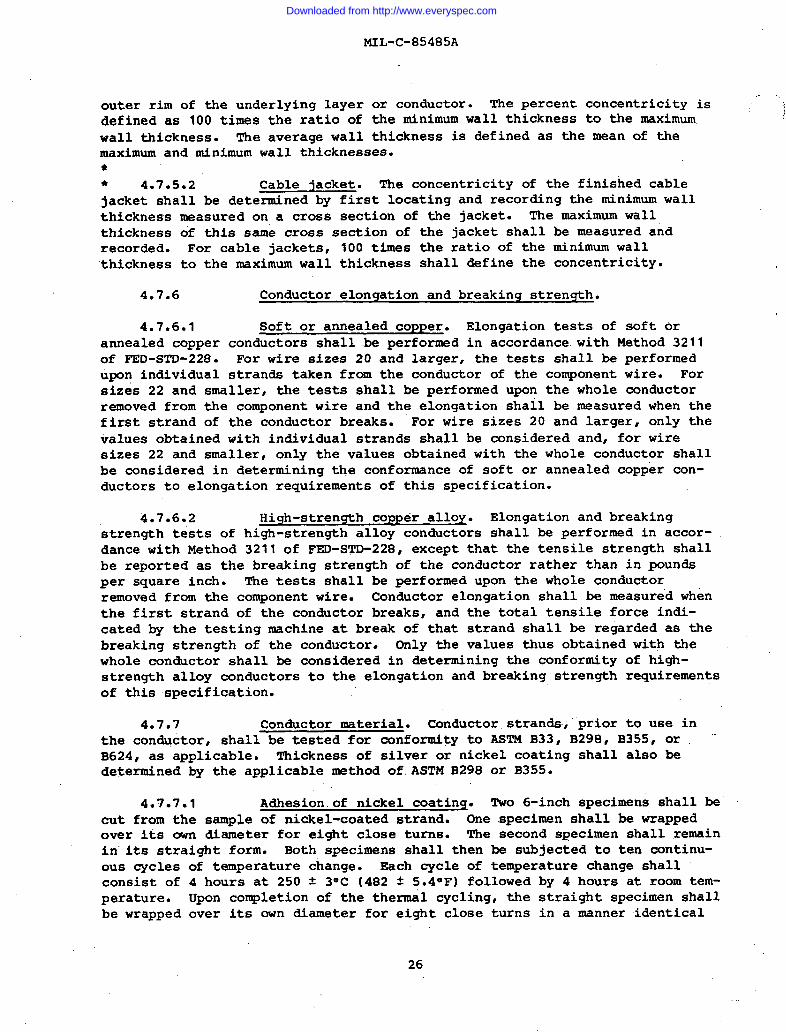
outer rim of the underlying layer or conductor. The percent concentricity is ;‘- “;defined as 100 times the ratio of the minimum wall thickness to the maximum j
wall thickness. The average wall thickness is defined as the mean of themaximum and minimum wall thicknesses.●
* 4.7.5.2 Cable jacket. The concentricity of the finished cablejacket shall be determined by first locating and recording the minimum wallthickness measured on a cross section of the jacket. The maximum wallthickness of this same cross section of the jacket shall be measured andrecorded. For cable jackets, 100 times the ratio of the minimum wall‘thickness to the maximum wall thickness shall define the concentricity.
4.7.6 Conductor elongation and breaking strength.
4.7.6.1 Soft or annealed copper. Elongation tests of soft orannealed copper conductors shall .beperformed in accordance with Method 3211of FED-sTD-228. For wire sizes 20 and larger, the tests shall be performedupon individual strands taken from the conductor of the component wire. Forsizes 22 and smaller~ the tests shall be performed upon the whole conductorremoved from the component wire and the elongation shall be measured when thefirst strand of the conductor breaks. For wire sizes 20 and larger, only thevalues obtained with individual strands shall be considered and, for wiresizes 22 and smaller, only the values obtained with the whole conductor shallbe considered in determining the conformance of soft or annealed copper con-ductors to elongation requirements of this specification.
4.7.6.2 High-strength copper alloy. Elongation and breakingstrength t@sts of high-strength alloy conductors shall be performed in accor-dance with Method 3211 of FED-STD-228, except that the tensile strength shallbe reported as the breaking strength of the conductor rather than in poundsper square inch. The tests shall be performed upon the whole conductorremoved from the component wire. Conductor elongation shall be measured whenthe first strand of the conductor breaks, and the total tensile force indi-cated by the testing machine at break of that strand shall be regarded as thebreaking strength of the conductor. Only the values thus obtained with thewhole conductor shall be considered in determining the conformity of high-strength alloy conductors to the elongation and breaking strength requirementsof this specification.
4.7.7 Conductor material. Conductor stranda;”prior to use inthe conductor, shall be tested for conformity to ASTM B33, B298, B355, or ‘“B624, as applicable. Thickness of silver or nickel coating shall also bedetermined by the applicable method of.ASTM B298 or B3SS.
4.7.7*1 Adhesion of nickel coatinq. TWO 6-inch specimens shall becut from the sample of nickel-coated strand. One specimen shall be Wappedover its own diameter for eight close turns. The second specimen shall remainin”its straight form. Both specimens shall then be subjected to ten continu-ous cyclesconsist ofperature.be wrapped
of temperature change. Each cycle of temperature change shall4 hours at 250 t 3° C (482 f 5.4° F) followed by 4 hours at room tem-Upon completion of the thermal cycling, the straight specimen shallover its own diameter for eight close turns in a manner identical
26
Downloaded from http://www.everyspec.com
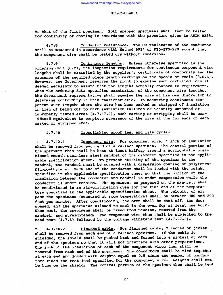
to that of the first specimen.
MIL-C-85485A
Both wrapped specimens shall then be testedfor continuity of coating in accordance with the procedure given in ASTM B355.
4.7.8 Conductor resistance. The DC resistance of the conductorshall be measured in accordance with Method 6021 of FED-STD-228 except thatthe component wire shall be tested dry without immersion.
4.7.9 Continuous lengths. Unless otherwise specified in theordering data (6.2), the inspection requirements for continuous component wirelengths shall be satisfied by tke supplier’s certificate of conformity and thepresence of the required piece length markings on the spools or reels (3.6.6).However, the Government reserves the right to exaxni.ne such certified lots ifdeemed necessary to assure that the lengths actually conform to requirement.when the ordering data specifies examination of the component wire lengths,the Government representative shall examine the wire at his own discretion todetermine conformity in this characteristic. In measuring continuous com-ponent wire lengths where the wire has been marked or stripped of insulationin lieu of being cut to mark insulation failures or identify untested orimproperly tested areas (4.7.17.2), such marking or stripping shall be con-idered equivalent to complete severance of the wire at the two ends of each
marked or stripped area.
4.7.10 Crosslinking proof test and life cycle.
4.7.10.1 Component wire. For component wire, 1 inch of insulationshall be removed from each end of a 24-inch specimen. The central portion ofthe specimen. then shall be bent at least halfway around a horizontally posi-tioned smooth stainless steel mandrel of the diameter specified in the appli-cable specification “sheet. .Toprevent sticking of the specimen to themandrel, the mandrel shall be covered with a dispersion coating of polytetra-fluoroethylene. Each end of the conductor shall be loaded with the weightspecified in the applicable specification sheet so that the portion of theinsulation between the conductor and mandrel is under compression while theconductor is under tension. The specimen, so prepared on the mandrel, shallbe conditioned in an air-circulating oven for the time and at the tempera-ture specified in the applicable specification sheet. The velocity of airpast the specimens (measured at room temperature) shall be between 100 and 200feet per minute. After conditioning, the oven shall be shut off, the dooropened, and the specimens allowed to cool in the oven for at least one hour.When cool, the specimens shall be freed from tension~ removed from themandrel, and straightened. The couponent wire then shall be subjected to-thebend test (4.7.3) followed by the voltage withstand test (4.7.27.2).
● 4.7.10.2 Finished cable. For finished cable, 2 inches of jacketshall be removed from each end of a 24-inch specimen. If the cable isshielded, the shield shall be pushed ba~ and formed into a pigtail at eachend of the specimen so that it will not interfere with other preparations.One inch of the insulation of each of the component wires then shall-beremoved from each end of the specimen. The conductors shall be tied togetherat each end and loaded with weights equal to 0.5 times the number of conduc-tors times the test load specified for the component wire. Weights shall notbe hung on the shield. The central portion of the specimen then shall be bent
27
Downloaded from http://www.everyspec.com
MIL-c-85485A
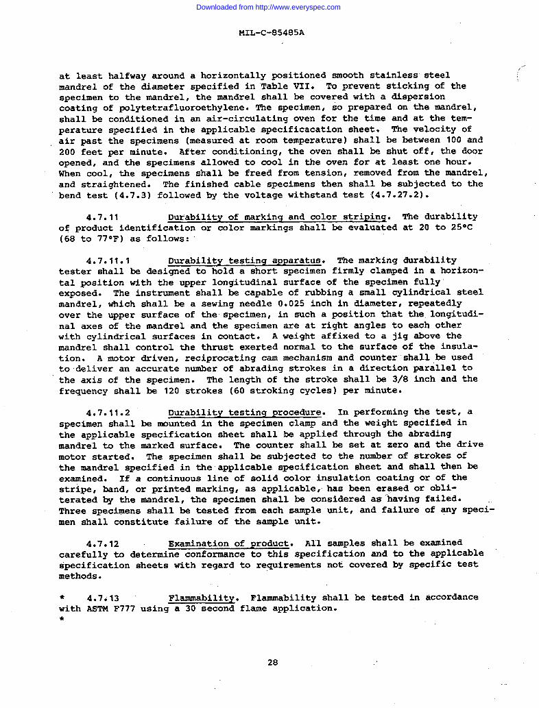
at least halfway around a horizontally positioned smooth stainless steelmandrel of the diameter specified in Table VII. To prevent sticking of thespecimen to the mandrel, the mandrel shall be covered with a dispersioncoating of Polytetrafluoroethylene. The specimen, so prepared on the mandrel,shall be conditioned in an air-circulating oven for the time and at the tem-perature specified in the applicable specificacation sheet. The velocity ofair past the specimens (measured at room temperature) shall be between 100 and200 feet per minute. After conditioning, the oven shall be shut off, the dooropened, and the specimens allowed to cool in the oven for at least one hour.When cool, the specimens shall be freed from tension, removed from the mandrel,and straightened. The finished cable specimens then shall be subjected to thebend test (4.7.3) followed by the voltage withstand test (4.7.27.2).
4.7.11 Durability of marking and color stripinq. The durabilityof product identification or color markings shall be evaluated at 20 to 25° C(68 to 77”F) as follows:
4.7.11.1 Durability testing apparatus. The marking durabilitytester shall be designed to hold a short specimen firmly clamped in a horizon-tal posit$on with the upperlongitudinal surface of the specimen fully’exposed. The instrument shall be capable of rubbing a small cylindrical steelmandrel, which shall be a sewing needle 0.025 inch in diameter, repeatedlyover the upper surface of the specimen, in such a position that the.longitudi-nal axes of the mandrel and the specimen are at right angles to each otherwith cylindrical surfaces in contact. A weight affixed to a jig above themandrel shall control the thrust exerted normal to the surface of the insula-tion. A motor driven, reciprocating cam mechanism and counter-shall be usedto deliver an accurate number of abrading strokes in a direction parallel tothe axis of the specimen. The length of the stroke shall be 3/8 inch and thefrequency shall be 120 strokes (60 stroking cycles) per minute.
4.7.11.2 Durability testing procedure. In performing the test, aspecimen shall be mounted in the specimen clamp and the weight specified inthe applicable specification sheet shall be applied through the abradingmandrel to the marked surface. The counter shall be set at zero and the drivemotor started. The specimen shall be subjected to the number of strokes ofthe mandrel specified in theapplicable specification sheet and shall then beexamined. If a continuous line of solid color insulation coating or of thestripe, band, or printed marking, as applicable, has been erased or obli-terated by the mandrel, the specimen shall be considered as-having failed.Three specimens shall be tested from each sample unit, and failure of qny speci-men shall constitute failure of the sample unit.
4.7.12 Examination of product. All samples shall be examinedcarefully to determine conformance to this specification and to the applicablespecification sheets with regard to requirements not covered by specific testmethods.
● 4.7.13 Flammability. Flammability shall be tested in accordance<with ASTM F777 using a 30 second●
flame application.
28
Downloaded from http://www.everyspec.com
MIL-C-85485A
4.7.14 Humidity resistance. A 52-foot specimen of component wireshall be subjected to the following:
4.7.14.1 Test apparatus. The apparatus shall consist of a testchamber capable of maintaining an internal temperature of 70 + 2° C (158 * 3.6° Fand an internal relative humidity of 95 2 5 percent. The test chamber shallbe capable of being so sealed as to retain the total moisture content in thetest space. The heat loss from the chamber shall be sufficient to reduce theinternal temperature from the above specified operating temperature to notmore than 38° C (1OO.4”F) within a period of 16 hours from the time of removalof the source of heat. Distilled or demineralized water shall be used toobtain the required humidity.
4.7.14.2 Test procedure. The specimen shall be placed in the testchamber and the temperature and relative humidity raised over a 2-hour periodto the values specified in 4.7.14.1 and maintained at such for a period of 6hours. At the end of the 6-hour period the heat shall be shut off. Duringthe following 16-hour period, the temperature must drop to 38°C (100.4°F) orlower. At the end of the 16-hour period, heat shall be again supplied for a2-hour period to stabilize at 70 * 2°C (158 * 3.6”F). This cycle (2 hoursheating, 6 hours at high temperature, 16 hours cooling) shall be repeated asufficient number of times to extend the total t~rne of tie test @ 360 hours(fifteen cycles). At the end of the fifteenth cycle, the 50-foot center sec-tion of the specimen shall be immersed in a 5 percent, by weight, solution ofsodium chloride in water at room temperature. The.insulation resistance ofthe specimen shall be measured with the outer surface of the specimengrounded, through an electrode in the electrolyte, and with a potential of 250to 500 volts DC applied to the conductor of the specimen after 1 minute ofelectrification at this potential. The insulation resistance shall be con-verted to megohms for 1000 feet by the calculation shown in 4.7.18.
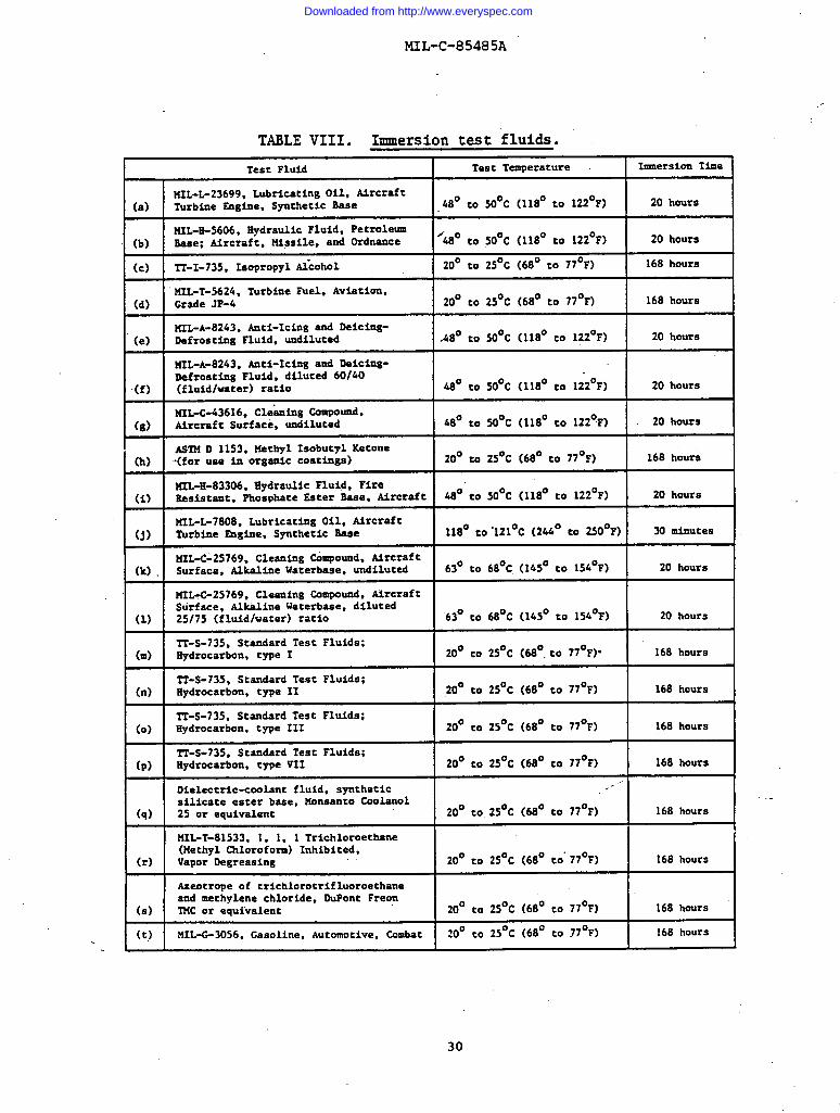
4.7015 Immersion. Specimens of component wire or finished cableof sufficient length to perforia the subsequent tests shall be measured “attheir midpoints to determine their initial diameters and then shall beimmersed to within 6 inches of their ends in each of the fluids (using aseparate specimen for each fluid) for the time and at the temperature speci-fied in Table VIII. During immersion, the radius of bend of the specimensshall be not less than 14 times, nor more than 35 times, the specified maximumdiameter of the component wire or finished cable under test. Upon removalfrom the fluids, the specimens shall remain for one hour in’-freeair at roomtemperature. The diameter’s then shall be remeasured at the original point of”measurement and compared to the initial diameters. The percent change indiameter then shall be calculated. For component wire, 1 inch of insulationshall be removed from each end of a 24-inch length of each specimen. Forfinished cable, 2 inches of the jacket shall be removed from “~ch end of a24-inch length of each specimen. If applicable, the shield shall be pushedback and fo,med into a pigtail at each end of the specimen. One inch of theinsulation of each of the component wires then shall be removed from each endof the specimen. The specimens then shall be subjected to the bend test(4.7.3), followed by the voltage withstand test (4.7.27.2).
29
)
I
Downloaded from http://www.everyspec.com
MIL-C-85485A
,., .
TABLE VIII. Immersion test fluids.
Test Fluid Test Temperature Inmiersion Time
M2L-L-23699, Lubricating Oil, Aircraft(a) Turbine Sngine, Synthetic Base 48° to 50° C (118° to 122° F) 20hours
H2L-S-5606, EydrauLic Fluid, Petroleum(b) Seee: Aircraft, Missile, and Ordnance ’48° to 50°C (118° CO 122° F) 20houre
(c) TT-I-735, Isopropyl A&ohol 20° to 2S°C (68° to 77°F) 168 hours
u2L_T-5621i, Turbine Fuel, Aviation,(d) Grade 1P-4 20° to 25° C (68° to 77° F) 168 hours
ML-A-8243, Anti-Icing and Deicing-(e) Defrosting Fluid, undiluted .48° to 50° C (118° CO 122° F) 20 hours
UIL-A-8243, Anti-Icing and Deicing-Defroeting Fluid, diluted 601k0
(f) (fluid/water) ratio 48° to SO°C (118° to 122° F) 20 hours
141-3616, CleAtig CO=POUI&(8) Aircraft Surface,uodiluted 48° to 50° C (118° CO 122° F) 20 hours
ASTM D 1153,MethylIsobucylKetone(h) -(foruae inurgemic coatinga) 20° to 25° c(68° to 77° F) 16S hours
t42L-11-83306,Ilydraulic Fluid, Fire(i) ltaaia~ant,Pho8phateSecer 8aae, Aircraft 48° to 50° C (118° to 122° F) 20 hours
M2L-L-7808,LubricatingOil, Aircraft(j) Turbine Eugine, Synthetic Seee 118° to”121° C (244°CO 250°F) 30 minutes
u2L-C-25769, Cleaning &mpound, Urcraft(k) Surface, ALkaLine Waterbaee, undiluted 63° to 68° C. (145° to 154° F) 20hours
UIL-C-25769, Cleaning Campound, AircraftSurface, Alkaline Waterbeee, diluted
(1) 25175 (fluid/water) ratio 63° to 68° C (145° to 154° F) 20 hours
IT-S-735, Standard Test Fluide;(m) Hydrocarbon, type I 20° to 25° C (68°. to 77°F)” 168 hours
~-S-735, Standard Test Fluids;(n) Iiydrocarbon, type 11 20° to 25° C (68° to 77° F) 168 houre
TT-S-735, Standard Test Fluids;(0) Hydrocarbon. type III 20° to 2S° C (68° to 77° F) 168 hours
TT-S-735,Standard Test Fluide;(p) Hydrocarbon, type VII 20° to 25° C (68° to 77° F) 168 hours
Dielectric-coolant fluid, synthetic.-
silicate ester base, Monsanto CooLanol(q) 25 or equtvalenc 20° to.25° C (68° to 77° F) 168 hours
NIL-T-81533, 1, 1, 1 Trichloroethane(Methyl Chloroform) Inhibited,
(r) Vapor Degreaeing ,. 20° CO 25° C(68°tO”770F) 168hours
Aseotrope of trichlorotrifluoroethaneand mechylene chloride, DuPont Freon
(s) TUC or equivalent 20° to 2S° C(68°to 77° F) 168hours
(t) t41L-G-3056, Gasoline,Automotive,Combat..
20° to 25° C (68° CO 77°F) 168 hoursi
30
Downloaded from http://www.everyspec.com
MIL-C-85485A
4.7.16 Insulation elongation and tensile strength.the entire component insulation shall be carefully removed from
Specimens ofthe conductor
and tested for tensile strength and elongation in accordance with FED-STD-228,Methods 3021 and 3031, respectively, using l-inch bench marks, a l-inch initialjaw separation, and a jaw separation speed of 2 inches per minute. Forfinished cable insulation, the method shall be the same, but only the cablejacket shall be tested.
4.7.17 Insulation and jacket flaws.
4.7.17.1 Spark test of comporientinsulation or cable jacket. Thecomponent wire or finished cable shall be passed through a bead chain elec-trode spark test device using the voltage and frequency specified in theapplicable specification sheet. The conductor and shield, as applicable,shall be grounded at one or both ends. The electrode shall be of a suitablebead chain or fine mesh construction that will give intimate metallic contactwith practically all the insulation surface. Electrode length and speed ofspecimen movement .shall be such that the insulation is subjected to the testvoltage for”a minimum of 0.2 second. lmy portion showing insulation breakdownshall be cut out including at least 2 inches of wire or cable on each side ofthe failure.
4.7.17.2 Impulse dielectric test of component insulation or cablejacket. Component wire or finished cable shall be tested in accordance withNEMA HP1-1979 at the voltage specified in the applicable specification sheet.For finished cable the conductor and shield, as applicable, shall be groundedat one or both ends. When specified in the c&tract or order (6.2) dielectricfailure, untested portions, or portions which have been exposed to fewer ormore than the specified number of pulses may be marked by stripping the insu-lation or by any other suitable method of marking as specified in the contractin lieu of being cut out of the wire or cable.
4.7.18 Insulation resistance. The uninsulated ends of a componentwire specimen at least 26 feet in length shall be connected to a positive DC -terminal and the specimen shall be immersed to within 6 inches of its ends ina water @th, at 25 * 5*C (77 * 9°F) , containing 0.5 to 1.0 percent of ananionic wetting agent. The specimen shall remain immersed for not less than 4hours, after which a potential of not less than 250 volts nor more than 500volts shall be applied between the conductor and the water bath which servesas the second electrode. The insulation resistance shall be determined after1 minute of electrification at this potential, and shall be expressed asmegohms for 1000 feet by the following calculation:
Megohms for 1000 feet =Specimen resistance (megohms) x immersed length (feet)
1000
4.7.19 Low temperature (cold bend). One end of the componentwire or finished cable specimen 36 inches in length shall be secured to arotatable mandrel in a cold chamber and the other end to the load weightspecified in the applicable specification sheet for component wire and to aload weight sufficient to keep the cable vertical and tangent for finished
31
Downloaded from http://www.everyspec.com
MIL-c-85485A
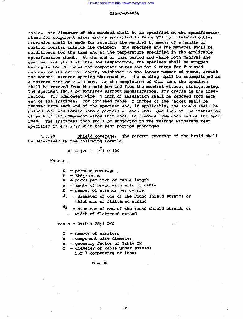
cable. The diameter of the mandrel shall be as specified in the specificationsheet for component wire~ and as specified in Table VII for finished cable.Provision shall be made for rotating the mandrel by means of a handle orcontrol located outside the chamber. The specimen and the mandrel shall beconditioned for the time and at the temperature specified in the applicablespecification sheet. At the end of this period and while both mandrel andspecimen are still at this low temperature the specimen shall be wrappedhelically for 20 turnsfor component wires and for 5 turns for finishedcables, or its entire length, whichever is the lesser number of turnst aroundthe mandrel without opening the chamber. The bending shall be accomplished ata uniform rate of 2 f 1 RPM. At the completion of this test the specimenshall be removed from the cold box and from the mandrel without straightening.The specimen shall be examined without magnification, for cracks in the insu-lation. For component wire, 1 inch of insulation shall be removed from eachend of the specimen. For finished cable, 2 inches of the jacket shall beremoved fro~ each end of the specimen and, if applicable, the shield shall bepushed back and formed into a pigtail at each end. One inch of the insulationof each of the component wires then shall be removed from each end of the spec-imen. The specimens then shall be subjected to the voltage withstand testspecified in 4.7.27.2 with the bent portion submerged.
4.7.20 Shield coverage. The percent coverage of the braid shallbe determined by the following formula:
K
Where:
K=F =.P =a =
E=
=(2F- ‘FZ) X 100
percent coverageEPd2/sin apicks per inch of cable lengthangle of braid with axis of cablenumber of strands per carrier
dl = diameter of one of the roundthickness of flattened strand
d~ = diameter of one of the roundwidth of flattened strand
tan a = 2T(D + 2dl) P/C
number of carrierscomponent wire diametergeometry factor of Table IXdiamete; of cable under shield;for 7 components or less:
D = Bb
shield strands or
shield strands or
32
Downloaded from http://www.everyspec.com
MIL-c-85485A
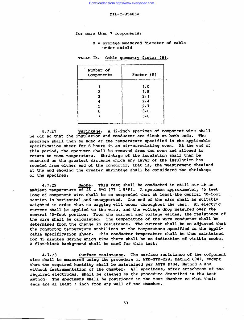
for more than 7 components:
D = average measured diameter of cableunder shield
TABLE IX. Cable geometry factor (B).
I Number ofComponents
L_1234567
Factor (B)
1*O1.82*12.42.73.03*O
4.7.21 Shrinkage. A 12-inch specimen of component wire shallbe cut so that the insulation and conductor are flush at both ends. Thespecimen shall then be aged at the temperature specified in the applicablespecification sheet for 6 hours in an air-circulating oven. At the end ofthis period, the specimen shall be removed from the oven and allowed toreturn to room temperature. Shrinkage of the insulation shall then bemeasured as the greatest distance which any layer of the insulation hasreceded from either end of the conductor; that is, the measurement obtainedat the end showing”the greater shrinkage shall be considered the shrinkageof the specimen.
4.7.22 Smoke. This test shall be conducted in still air at anambient temperature of 25 t 5° C (77 ~ 9“F). A specimen approximately 15 feetlong of component wire shall be so suspended that at least the central 10-footsection is horizontal and unsupported. One end of the wire shall be suitablyweighted in order that no sagging will occur throughout the test. An electriccurrent shall be applied to the wire, and the voltage drop measured over thecentral 10-foot portion. From the current and voltage values, the resistance ofthe wire shall’be calculated. The temperature of the wire ~nductor shall bedetermined from the change in resistance. The current shall be so adjusted thatthe conductor temperature stabilizes at the temperature specified in the appli-cable specification sheet. This conductor temperature shall be thus maintainedfor 15 minutes during which time there shall be no indication of visible smoke.A flat-black background shall ’be used for this test.
4.7.23 Surface resistance. The surface resistance of the componentwire shall be measured using the procedure of FED-STD-228, Method 6041~ exceptthat the required humidity shall be maintained per ASTM E104, Method A andwithout instrumentation of the chamber. All specimens, after attachment of therequired electrodes, shall be cleaned by the procedure described in the testmethod. The specimens shall be positioned in the test chamber so ~at theirends are at least 1 inch from any wall of the chamber.
I
I
33
Downloaded from http://www.everyspec.com
I
MIL-C-85485A
I * 4.7.24 Surface transfer impedance, effective.
* 4.7.24.1 ESQX!!%*The method to be described is a modification ofMethod 1, Section 5, of IEC Standard 96-1A. The modifications are for experi-mental convenience, and to extend the usable frequency range. The effectivesurface transfer impedance is determined upon a 1 t 0.01 m length of cable.
* 4.7.24.2 Sample preparation. Approximately 4 feet of the cableshall be prepared in the following manner. Approximately 3 inches of thecable jacket shall be removed from one end of the cable and the shield pushedback to expose the insulated conductor. The insulation shall be removed fromthe conductor to within 1 inch of the pushed back shield as shown in Figure 2,step 1. For a multiconductor cable, all the conductors shall be connectedtogether and these connected wires shall be referred to as “the conductor.”
,, The shield shall then be pulled forward over the remaining insulation andsoldered to the conductor. The shield shall completely enclose the insulatedconductor, shall be soldered around 3600 of the conductor and all disturbedportions of the shield shall be well soldered. The conductor shall extendbeyond the soldered joint and shall be formed and trimmed so as to be able tobe soldered into the center pin of a TNC female-female adapter (see Figure 2,step 2). Excess shield, beyond the solder joint, shall be removed and thecenter pin of the adapter shall be attached to the conductor so that the pinis within 1/2 inch of the soldered joint. A piece of shrink tubing or otherappropriate material shall be applied over the soldered joint to insulate thejoint (see Figure 2, step 3). The adapter pin shall then be inserted into theTNC adapter as shown in Figure 2, step 4. A metallic outer braid shall bepulled over the entire length of the cable and shall extend halfway over the
TNC adapter. The outer braid shall then be soldered to the TNC adap”ter,making sure that a 3600 solder joint is formed (see Figure 2, step 5). Shrinktubing shall be applied over the entire length of the outer braid ensuringthat the outer “braid is pressed firmly and consistently to the jacket of thecable (see Figure 2, step 6). During the application of the joint insulatingtubing, outer braid and overall shrink tubing, the exact location of thesoldered joint between the shield and conductor shall be noted by marking eachlayer at that location in some suitable manner. The other end of the cable,with the outer braid and shrink tubing applied, shall be terminated in thefollowing manner. At a distance of 38 inches from the mark on the tubingwhich indicates the location of the shield to conductor joint, the shrinktubing shall be cut circumferentially and all tubing futher than 38 inchesfrom that mark shall be removed. The outer braid which hasbeen exposed shallbe cut back to within “2inches of the shrink tubing and the severed braidremoved. The remaining 2 inches of outer braid shall then be pushed back toexpose the cable underneath. The cable jacket shall be window stripped toexpose the shield for a distance of 1/2 inch. The center of this window cutin the cable jacket shall be 1.00 t 0.01 meters from the mark on the outershrink tubing which indicates the location of the joint between the shield andthe conductor. The end of the cable shall then be cut and prepared for ter-mination with a TNC male plug such that the distance from the installed plugto the window in the cable jacket is 1/4 to 1/2 inch. The prepared cable will.appear as shown in Figure 3, step 1. The.TNC male plug shall be installed andthe outer braid pulled forward over the exposed cable shield and the shield’andouter braid shall be soldered together for 360° around the cable as shown in
34
Downloaded from http://www.everyspec.com
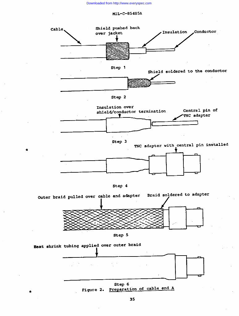
MIL-c-85485A
*
Cable
\
Shield pushed back
/1nsu17c0nd.”or
fI
Step 1Shield soldered to the conductor
Step 2
Insulation overshield/contictor termination Central pin
I/
TNC adapter
1
of
Step 3TNC adapter with central pin
. n
installed
Step 4
Outer braid pulled over cable and adapter Braid soldered to adapterI /
Step 5
Heat shrink tubing applied over outer braid
Step 6Figure 2. Preparation of cable end A*
35
Downloaded from http://www.everyspec.com
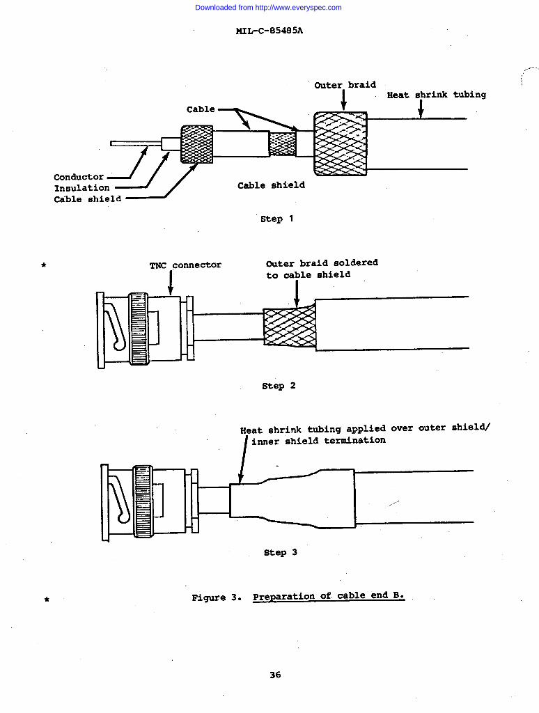
*
MIL-C-85485A
Outer bral,dHeat shrink tubing
Cable
I
J?ConductorInsulation Cable shield~ble shield
Step 1
TNC connector Outer braid solderedto cable shield
Step 2
Heat shrink tubing applied over outer shield/
I
inner shield termination
1 I
,
h --+/
,...-”’
Step 3
Figure 3. Preparation of cable end B.
36
,,-”””’..
Downloaded from http://www.everyspec.com
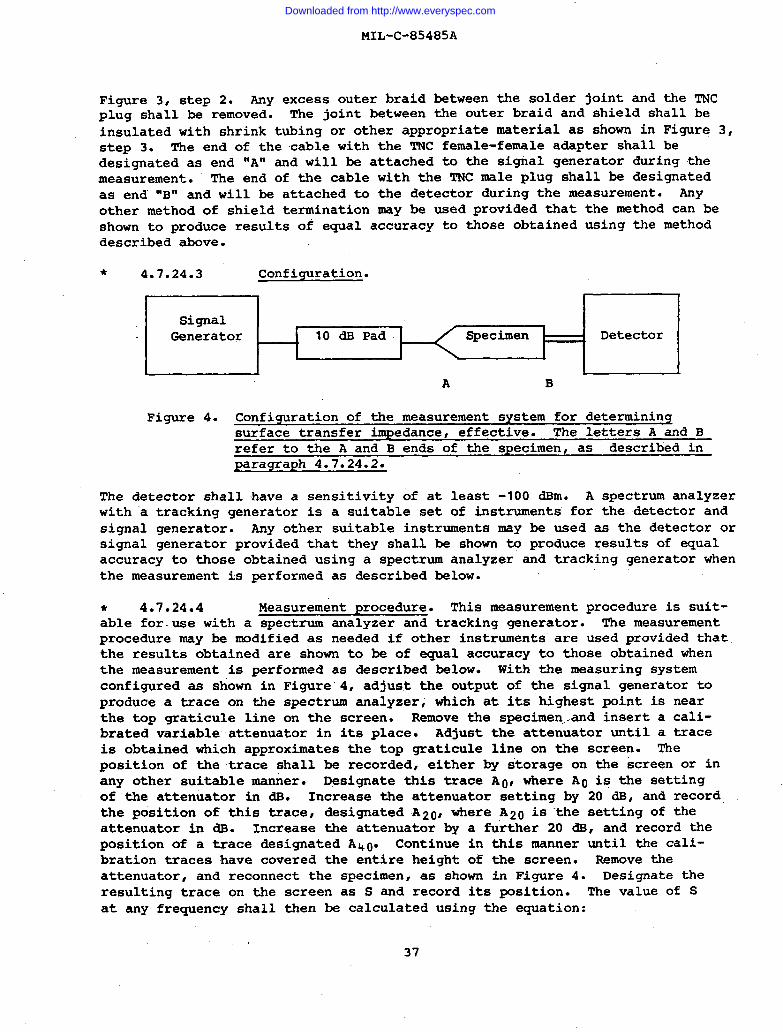
MIL-C-85485A
Figure 3, step 2. WY excess outer braid between the solder joint and the TNCplug shall be removed. The joint between the outer braid and shield shall beinsulated with shrink tubing or other appropriate material as shown in Figure 3,step 3. The end of the cable with the TNC female-female adapter shall bedesignated as end “A” and will be attached to the signal generator during themeasurement. The end of the cable with the TNC male plug shall be designatedas end “B” and will be attached to the detector during the measurement. myother method of shield termination may be used provided thatshown to produce results of equal accuracy to those obtaineddescribed above.
* 4.7.24.3 Configuration.
m
the method can beusing the method
I I“1Generator
1---10 ~ Pad
ISpecimen
HDetector I
l——__.l ————— —------~A B
Figure 4. Configuration of the measurement system for determiningsurface transfer impedance, effective. The letters A and Brefer to the A and B ends of the specimen, as described inparagr aph 4.7.24.2.
The detector shall have a sensitivity of at least -100 dBm. A spectrum analyzerwith ‘a tracking generator is a suitable set of instruments for the detector andsignal generator. my other suitable instruments may be used as the detector orsignal generator provided that they shall be shown to produce results of equalaccuracy to those obtained using a spectrum analyzer and tracking generator whenthe measurement is performed as described below.
* 4.7.24.4 Measurement procedure. This measurement procedure is suit-able for.use with a spectrum analyzer and tracking generator. The measurementprocedure may be modified as needed if other instruments are used provided thatthe results obtained are shown to be of equal accuracy to those obtained whenthe measurement is performed as described below. With the measuring systemconfigured as shown in Figure”4, adjust the output of the signal generator toproduce a trace on the spectrum analyzer, which at its highest point is nearthe top graticule line on the screen. Remove the specimen.and insert a cali-brated variable attenuator in its place. Adjust the attenuator until a traceis obtained which approximates the top graticule line on the screen. Theposition of the trace shall be recorded, either by storage on the ‘screenor inany other suitable mafier. Designate this trace A~, where AO is the settingof the attenuator in dB. Increase the attenuator setting by 20 m, and recordthe position of this trace, designated A2~, where A20 is ““thesetting of theattenuator in dB. Increase the attenuator by a further 20 d8, and record theposition of a trace designated A40. Continue in this manner until the cali-bration traces have covered the entire height of the screen. Remove theattenuator, and reconnect the specimen, as shown in Figure 4. Designate theresulting trace on the screen as S and record its position. The value of Sat any frequency shall then be calculated using the equation:
37
Downloaded from http://www.everyspec.com
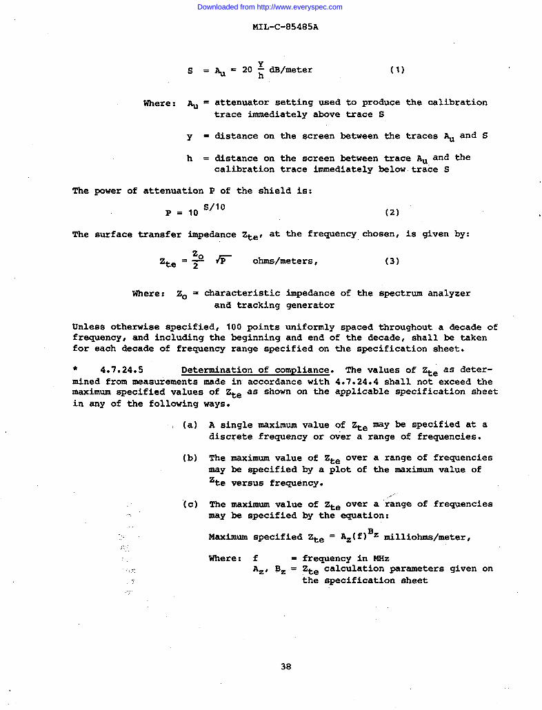
Where: AU’
Y =
h=
MIL-C-85485A
Au =20: dB/meter (1)
attenuator setting used to producetrace immediately above trace S
distance on the screen between the
the calibration
traces & and S
distance on the screen between trace ~ and thecalibration trace immediately below trace S
The power of attenuation P of the shield is:
P= ,0 s/lo
(2)
The surface transfer impedance Zte, at the frequency chosen, is given by:
20Zte = ~ Jr ohms/meters, (3)
Where: 20 = characteristic impedance of the spectrum analyzerand tracking generator
Unless otherwise specified, 100 points uniformly spaced throughout a decade offrequency, and including the beginning and end of the decade, shall be takenfor each decade of frequency range specified on the specification sheet.
● 4.7.24.5 Determination of compliance. The values of Zte as deter-mined from measurements made in accordance with 4.7.24.4 shall not exceed themaximum specified values of ~e as shown on the applicable specification sheetin any of the following ways.
...
...-,
(a)
(b)
(c)
...,.!
A single maximun value of ~e may be specified at adiscrete frequency or over a range of frequencies.
The maximum value of Zte over a range of frequenciesmay be specified by a plot of the maximum value of
‘te versus frequency.,...
The maximum value of ~e over a ‘range of frequencies-y be specified by the equation:
Maximum specified !+e = Az(f)Bz milliohms/meter,
Where: f = frequency in MHzA=, B= = Zte calculation parameters given on
the specification sheet
38
Downloaded from http://www.everyspec.com
MIL-C-85485A
4.7.25 Thermal shock resistance.
● 4.7.25.1 Preparation of specimen. A specimenfive feet long shall be prepared by carefully removing 1from each end of the wire. A specimen of finished cable
of component wireinch of insulationfive feet long shall
be prepared by cutting the component wires, shield and jacket flush at eachend, then carefully removing one inch of jacket from each end of the cable.A razor blade or equivalent, held perpendicular to the axis of the wire, shallbe used to cut the insulation or jacket for the removal operation. Thedistance between the end of the conductor and the insulation or jacket at eachend of the specimen shall be measured to the nearest 0.01 inch. The specimenshall be formed into a loose coil not less than 1 foot in diameter and shallbe laid on a wire screen for handling throughout the test.
● 4.7.25.2 Test procedure. The specimen shall be placed for 30 minu-tes in a preheated air-circulating oven at the temperature specified in theapplicable specification sheet. The specimen shall then be removed from theoven and, within two minutes, placed in a chamber which has been precooledto -55 f 20C (-67 * 3.60F). It shall be exposed to this temperature for 30minutes, after which it shall be removed and allowed a minimum of 30 minutesto return to room temperature, ’20to 25° C (68 to 77”F). At the conclusion ofthis cycle, the distance from the end of each layer of insulation, or jacketfor finished cable specimens, to the end of the conductor shall be measured tothe nearest O.Ol”inch. This thermal shock cycle and the measurements shall berepeated for an additional three cycles (a total of four cycles). Any measure-ment varying from the original measurement by more than the amount specifiedin the applicable specification sheet shall constitute failure. Any flaringof any layer shall also constitute failure.
4.7.26 Thermal stability. A 10-foot sample of cable shall beformed into a loose coil approximately 1 foot in diameter and aged in a cir-culating air oven for the time and temperature specified in the applicablespecification sheet. The velocity of air past the sample (measured at roomtemperature) shall be between 100 and 200 feet per minute. After aging, thesample shall be allowed to cool to room temperature and shall then be sub-jected to the voltage withstand test of 4.7.27.1. A 6-inch specimen shallthen be cut from the center of the 10-foot sample. This 6-inch specimenshall be used to determine the stop band attenuation of the aged cable inaccordance with 4.7.2.
4.7.27 Voltage withstand.
4.7..27.1 Voltage withstand (dielectric). Voltage withstand(dielectric) tests shall be performed upon 100 percent of all finishedcable by applying the specified voltage between each conductor or shield inturn and all the other conductors and shields which shall be tied togetherand grounded. The test voltage shall be as specified in the applicablespecification sheet and the time of electrification shall be not less than15 seconds nor more than 30 seconds.
4.7.27.2 Voltage withstand (post-environmental). The specimenshall be immersed in a 5 percent, by weight, solution of sodium chloride inwater at 20 to 25° C (68 to 77° F) , except that the uninsulated ends and 1.5
39
Downloaded from http://www.everyspec.com
MIL-C-85485A
inches of insulated wire or cable at each end of the specimen shall protrudeabove the surface of the solution. After immersion for 5 hours, the voltagespecified in the applicable specification sheet shall be applied between theconductor, or the shield as applicable, and an electrode in contact with theliquid. The voltage shall be gradually increased at a uniform rate from zeroto the specified voltage in 0.5 minute, maintained at that voltage for aperiod of 5 minutes for component wire specimens and 1 minute for finishedcable specimens, and, gradually reduced to zero in 0.5 minute.
4.7.28 @!3&” The weight of each lot of component wire orfinished cable shall be determined by Procedure I (4.7.28.1). Lots failingto meet the weight requirement of the applicable specification sheet whentested in accordance with Procedure I shall be subjected to Procedure II.All reels or spools failing to meet the requirements of the applicablespecification sheet when tested by Procedure II shall be rejected. Thesampling plans of 4.4.1 are not applicable in Procedure 11.
4.7.28.1 Procedure I. The length and weight of a specimen at least10 feet long shall be accurately measured and the resultant measurements con-verted to pounds per 1000 feet.
4.7.28.2 Procedure II. The net weight of the component wire orfinished cable on each reel or spool shall be obtained by subtracting thetare weight of the reel or spool from the gross weight of the reel or spoolcontaining the component wire or finished cable. The net weight of componentwire or finished cable on each reel or spool shall be divided by the accu-rately determined length of component wire or finished cable on that reel orspool and the resultant figure converted @ pounds per 1000 feet. “Whenwoodor other moisture absorbent materials are used for reel or spool construction,weight determinations shall be made under substantially uniform conditions ofrelative humidity.
* 4.7.29 Wrap test. A 12-inch specimen of component wire shall bebent back on itself at the mid-portion, on a radius not less than the radiusof the wire, and one end of the specimen shall be wrapped tightly around theother end as a mandrel for a total of four close turns. The specimen shallthen be placed in an air-circulating oven and conditioned for the time and atthe temperature specified in the applicable specification sheet. After con-ditioning, the specimen shall be removed from the oven and,,examined visuallywithout the aid of magnification for cracks.
...
●
5. PREPARATIONFORDELIVERY
* 5.1 Packaginq. Packaging shall be Level A or C in accordancewith MIL-C-12000. Unless otherwise s~ecified in the order (6.2), Level Ashall be applicable.
* 5.1,1 Level A. Packaging shall be in accordance with the Level Arequirements of MIL-C-12000 and as follows:
40
Downloaded from http://www.everyspec.com
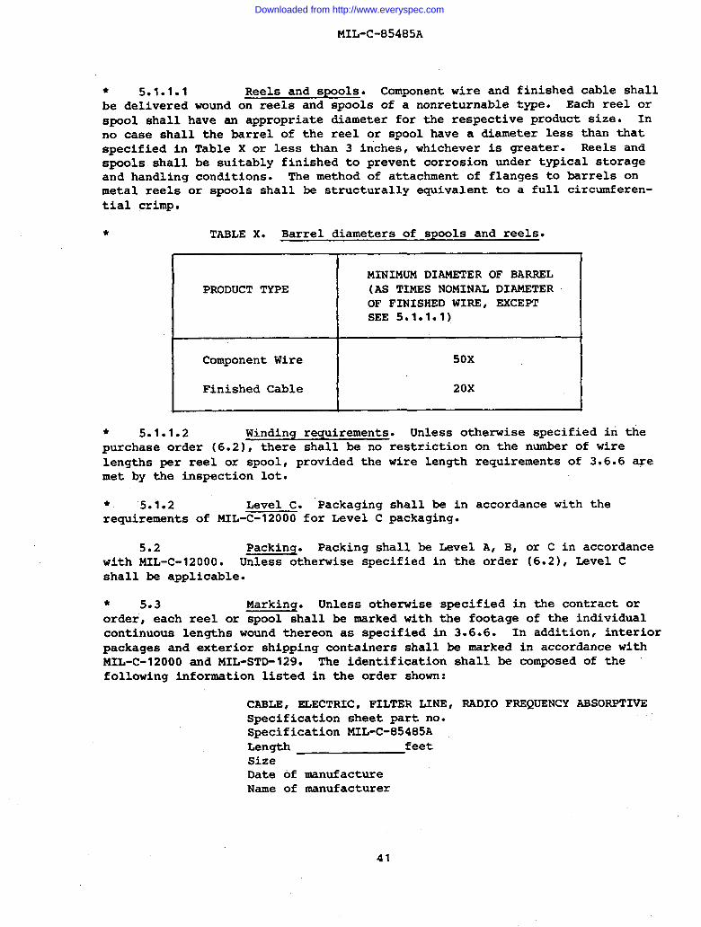
MIL-C-85485A
● 5.1.1.1 Reels and spools. Component wire and finished cable shallbe delivered wound on reels and spools of a nonreturnable type. Each reel orspool shall have an appropriate diameter for the respective product size. Inno case shall the barrel of the reel or spool have a diameter less than thatspecified in Table X or less than 3 inches, whichever is greater. Reels andspools shall be suitably finished to prevent corrosion under typical storageand handling conditions. The method of attachment of flanges to barrels onmetal reels or spools shall be structurally equivalent to a full circumferen-tial crimp.
* TABLE X. Barrel diameters of spools and reels.
PRODUCT TYPE
1’
E
MINIMUM DIAMETER OF BARREL(AS TIMES NOMINAL DIAMETEROF FINISHED WIRE, EXCEPTSEE 5.1.1.1)
50X
20X
* 5.1.1.2 Winding requirements. Unless otherwise specified in thepurchase order (6.2), there shall be no restriction on the nwer of wireiengths per reel or spool, provided the wire length requirements of 3.6.6 wemet by the inspection lot.
*, 5.1.2 Level C. Packaging shall be in accordance with therequirements of MIL-C-12000 for Level C packaging.
5.2 Packing. Packing shall be Level A, B, or C in accordancewith MIL-C-120000 Unless otherwise specified in the order (6.2), Level Cshall be applicable.
* 5.3 Marking. Unless otherwise specified in the contract ororder, each reel or spool shall be marked with the footage of the individualcontinuous lengths wound thereon as specified in 3.6.6. In addition, interiorpackages and exterior shipping containers shall be marked in accordance withMIL-C-12000 and MIL-STD-129. The identification shall be composed of thefollowing information listed in the order shown:
CABLE, ELECTRIC, FILTER LINE, RADIO FREQUENCY ABSORPTIVESpecification sheet part no.Specification MIL-C-85485ALength feetSizeDate of manufactureName of manufacturer
41
Downloaded from http://www.everyspec.com
MIL-C-85485A
6. NOTES
6.1 Intended use.specification are intended for usecharacteristics are required. The
The electric cables covered by thisin any application where their performancecables are suitable for installation on
aerospace electrical systems within the limitations of applicable performancerequirements.
6.1.1 Temperature rating. Temperature ratings as specified inspecification sheets pertaining to this specification represent the maximumpermissible continuous operating temperature of the conductor. The maximumambient temperature should be the rated maximum conductor temperature of thewire diminished by the operating rise”in temperature of the conductor.,
6.1.2 Size designations. The conductor sizes and the corre-sponding size des@nations of this specification are in accordance withestablished usage for.stranded copper conductors for hookup wire in theelectronic and aircraft industries. These sizes and size designations arenot identical with American Wire Gage (AWG) sizes for solid wire and strands.The diameters and cross-sectional areas of the stranded conductors of thisspecification are, in most sizes, only roughly approximate to those of AWGsolid conductors of the same numerical size designation.
* 6.1.3 Installation. Installation technique is critical to per-formance of this product for its intended use. Refer to procuring activityfor proper installation instructions.
6.2 Ordering data. Procurement documents should specify thefollowing:
[a)
(b)
(c)
(d)
(e)
(f)
(g)
Title, number, and date of this specification.
Applicable specification sheet number, title, and date.
Applicable specification sheet part number.
Color required (3.6.3).
Quantity required. ,..,-Levels of packaging and packing required.
Exceptions, if any, to the optional provisions of thisspecification including:
(1) Applicable product identification requirements,if other than specified in 3.6.7.
(2) Applicable minimum length requirements.
(3) Responsibility for inspection, if other thanspecified in 4.1.
42
Downloaded from http://www.everyspec.com
MIL-C-85485A
(4) Marking of dielectric test failures by strippingof insulation or by other method specified inthe contract in lieu of cutting of the componentwire or finished cable, if applicable (4.7.17.2).
(5) Special preparation for delivery requirements, ifapplicable (Section 5).
6.3 Qualification. With respect to products requiring qualifi-cation, awards will be made only for such products as have, prior to thetime set for opening of bids, been tested and approved for inclusion in theapplicable Qualified Products List (QPL) whether or not such products haveactually been so listed by that date. The attention of the suppliers iscalled to this requirement, and manufacturers are urged to arrange to havethe products that they propose to offer to the Government tested for quali-fication in order that they may be eligible to be awarded contracts or ordersfor the products covered by this specification. The activity responsiblefor the Qualified Products List is the Naval Air Systems Command, Washington,DC 20360; however; application for qualification of products should be madeto the Commanding Officer, Naval Avionics Center (Code D/714), 6000 East 21stStreet, Indianapolis, Indiana 46218, who has been designated Naval AirSystems Command agent for establishing this Qualified Products List.
“6.3.1 Conformity to qualified sample. It is understood thatcomponent wire or finished cable supplied under contract shall be identicalin every respect to the qualification sample tested and found satisfactory,except for changes previously approved by the Government. Any unapprovedchanges from the qualification sample shall constitute cause for rejection.
* 6.4 Patent notice. The Government has a royalty-free licenseunder Patent No. 4,347,487 for the benefit of manufacturers of radio frequencyabsorptive, filter line cable having a conductive jacket either for the Govern-ment or for use in equipment to be delivered to the Government,
● 6.5 Changes from previous issue. The paragraphs of thisspecification are marked with an asterisk to indicate where changes from theprevious issue were made. This was done as a convenience only and theGovernment assumes no liability whatsoever for any inaccuracies in these nota-tions. Bidders end contractors are cautioned to evaluate the requirements ofthis document based on the entire content irrespective of.the marginal nota-tions and relationship to the previous issue.
Custodian:AF - 85
Preparing Activity:Navy - AS
(Project No. 6145-0840)Review Activity:
AF - 19
*U.S. GOVERNMENT PRINTING OFFICE: 1983+ 0S+34!2846
43
Downloaded from http://www.everyspec.com
STANDARDIZATION DOCUMENT IMPROVEMENT PROPOSAL(SeeInstructions- ReverseSide)
. DOCUMENT NIJM6EF! 2. DOCUMENT TITLE
b. NAME OF SUBMITTING ORGANIZATION 4. TYPE OF ORGANIZATION (Mark one)
I ❑ VENOOR
❑ USERL ADDRESS (Stwet, City, Stata, ZIP (%da)
m MANUFACTURER
❑ oT”ER,sp@ctfy):
1i. PROBLEM AREASa Paragraph Number and Wordina:
..b. Recommended We-ding:
c. ReaaonIRationale fo? Racommandation:
i. REMARKS
,“
h NAME OF SUBMITTER (Laet, First, Mf) - Optional b. WORK TELEPHONE NUMBER (Jnclda Arcode) - optional
. MAILING ADORESS (Stn?et, City, State,ZIP Code) - OPtiOIId 8. DATE OF SUBMISStON (YYMMDD)
..~
1
J
I \
o~ &Ofl&1426 PREVIOUS EDITION IS OSSOLETE.
Downloaded from http://www.everyspec.com