Embed Size (px)
Citation preview

Methods for reaching ultra-low vertical emittance: the SLS experience
Masamitsu Aiba, Michael Böge, Natalia Milas, Andreas Streun, PSI
1. Vertical emittance
1.1 Quantum limit
1.2 Coupling
2. Machine preparation 2.1 Orbit correction
2.2 Optics correction
2.3 BPM roll measurement
2.4 Knobs for coupling control
2.5 Emittance monitor
Low-e-ring workshop, Iraklion, Oct. 3-5, 2011
3. Girder realignment 3.1 SLS dynamic alignment
3.2 Beam based girder alignment
3.3 Survey based girder alignment
4. Emittance minimization 4.1 Vertical dispersion measurement
4.2 Vertical dispersion suppression
4.3 Coupling correction
4.4 Orbit manipulation
4.5 Emittance achievements
Conclusion & Outlook

1. Vertical emittance
1.1 Quantum limit direct photon recoil,
1/g radiation cone T. O. Raubenheimer, Tolerances to limit the
vertical emittance in future storage rings, SLAC-PUB-4937, Aug.1991
independent of energy!
examples: SLS 0.20 pm MAX-IV 0.05 pm PETRA-III 0.04 pm
lower limit of vertical emittance
quantum emittance << coupling
G(s) =curvature, Cq = 0.384 pm
pm09.0Mag
e
y
y
isomagnetic lattice

Coupling (diff. and sum resonances) from skew quads,
sextupole heaves and quad rolls.
1.2. Vertical emittance with coupling A. Franchi et al., Vertical emittance reduction and
preservation in electron storage rings via resonance drive terms correction, PRSTAB 14, 034002 (2011)
Vertical correctors, bend rolls, quad heaves
Vertical
dispersion Eigen-e (invariant)
Projected e (s)
Apparent e (s)
h10010 & h10100
h01001

Vertical emittance properties
Apparent-e oscillates around the lattice. – oscillation amplitude is lower for low coupling
Projected-e changes at skew quad kicks.
Eigen-e is invariant.
Many monitors average: < App. e > Eigen-e Minimization of apparent
e at one location minimizes eigen-e too:
Simulation (TRACY, 100 seeds,
SLS with 6 skew quads):
Eigen-e results, when optimizing
on beam size at monitor () vs.
optimizing on eigen-e itself ( ).
Å. Andersson et al., NIM A 592
(2008) 437-446

2.1 Orbit correction
Fast orbit feedback (0dB @ 100Hz, 300 nm resolution)
Beam based BPM calibration (“beam based alignment”)
2. Machine preparation
BBA measurement vs. mechanical measurement

2.2 Optics correction
Results on beta beat correction (x / y, RMS) (Measurement vs. model)
QV (tune shift from quad variation) 4.0% / 3.2%
LOCO (fit to response matrix) 2.0% / 2.0%
TBT (turn by turn data) 1.4% / 3.6% Required BPM synchronization upgrade and data reconstruction to eliminate turn-to-turn crosstalk.
M. Aiba, Comparison of linear optics correction means at
the SLS, Proc. IPAC-2011

2.3 BPM roll measurements
Methods: – Local bumps (150 mm) with fast orbit feedback:
get BPM roll from corrector currents.
– LOCO fit to response matrix.
Prerequisite: corrector roll << BPM roll
BPM roll: 17 mrad RMS.
Origin: electronics.
Spoils measurements of vertical dispersion.
Low level implementation as “3rd BBA constant”: BPM sway, heave & roll
M. Böge et al., The Swiss Light Source – a test-bed for damping ring optimization, Proc. IPAC-2010
Correlation of two BPM roll measurements

2.4 Knobs for coupling control
120 sextupoles (9 families) with additional coils:
– 72 wired as horizontal/vertical orbit correctors.
– 12 wired as auxiliary sextupoles for sextupole resonance
suppression (empirical).
– 36 wired as skew quadrupoles:
12 dispersive, 24 non-dispersive.
Skew quads from orbit bumps in 120 sextupoles: 72 dispersive, 48 non-dispersive “skew quads”
a2 = 2b3 yo

2.5 Emittance (beam size) monitor
p-polarization method:
image of vertically
polarized visible-UV
synchrotron radiation.
Get beam height from
“valley”- intensity:
lookup-table of SRW
simulations.
Resolution:
Beam height 0.5 mm
Emittance 0.7 pm (incl. dispersion subtraction)
Åke Andersson’s talk
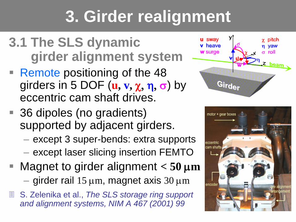
3.1 The SLS dynamic girder alignment system
Remote positioning of the 48 girders in 5 DOF (u, v, c, h, s) by eccentric cam shaft drives.
36 dipoles (no gradients) supported by adjacent girders. – except 3 super-bends: extra supports
– except laser slicing insertion FEMTO
Magnet to girder alignment < 50 mm
– girder rail 15 mm, magnet axis 30 mm
S. Zelenika et al., The SLS storage ring support and alignment systems, NIM A 467 (2001) 99
3. Girder realignment

3.2 Beam based girder alignment
48 girders (shift & angle) = 96 “correctors”
Response & correction matrices for – orbit correction (saves 75% CH, 100% CV strength ! ),
– or, vertical dispersion suppression.
Orbit based remote girder alignment rejected: – Mistrust in girder moving procedures.
– Possible negative impact on user operation.
Vertical dispersion girder response and correction matrices and SVD weights

3.3 Survey based girder realignment
Girder heave and pitch from survey
Align girders to medium line (long wavelength
machine deformation
is not a problem)
Fast orbit
feedback active
correctors
confirm
girder move.
M. Böge et al., SLS vertical emittance tuning, Proc. IPAC-2011

Corrector strengths before and after girder realignment, and
after beam based BPM calibration* (sector 1)
(*girder move causes vacuum chamber deformation)
Factor 4 reduction of rms CV kick in sector (= 4 girders)

Status (Sep.2011) : done, partially done, malfunction
Sector 1 2 3 4 5 6 7 8 9 10 11 12
Vertical corrector kick (all CV) 140 81 mrad rms
(expect 60 mrad rms after repair of sectors 4,9,11)
Re-establishment of “train link” between G06 and G07
G07 pitch 70 mm, confirmed by hydrostatic leveling system
Manual alignment of super-bend between G06/G07
Improvement for beam line too.
reference
heave

4.1 Vertical dispersion measurement
Vertical orbit as function of energy
Upgrade of RF oscillator for fast frequency shift
Prerequisite: determination of BPM roll errors.
4. Emittance minimization
Vertical dispersion
measurement
Energy range ± 0.3%
(-Df = ± 920 Hz)
20 points
10 minutes
65 mm resolution

4.2 Vertical dispersion suppression
12 dispersive skew quadrupoles ( Dx 33 cm )
73 BPMs 73 12 dispersion response matrix
Feed in measured Dy apply measure again.
Best results up to now: Dy 1 mm RMS.
1232 2)(
')'()(cos)'()'(sin2
)()(
aDayDbybsF
dsQssssFQ
ssD
xcoxco
y
C
y
y
y
y
-
-- pmmp
orbit bump in quadrupole vertical dipole
orbit bump in dispersive sextupole dispersive skew quadrupole

4.3 Betatron coupling correction
24 non-dispersive skew quads.
from model: coupled response matrix as function of skew quad strength: Jacobian {RM/ a2k}.
73 BPMs and CH/CV: 146 146 24 tensor.
Rearrange: 21316 24 matrix SVD-inversion. – Alternative: use only coupled RM-quadrants:
73 73 24 tensor 5329 24 matrix.
Feed in measured orbit response matrix.
Fit 24-vector {Da2} of skew quad strengths.
Apply inverse to machine: -{Da2} .
Iterate within model for large errors.
Compensates also betatron coupling increase from previous vertical dispersion suppression.

4.4 Orbit manipulation
“dispersion free steering”
Orbit bumps: – get skew quads from sextupoles
– get vertical dipoles from quadrupoles
Simultaneous suppression of vertical dispersion and betatron coupling.
Individual corrector method: use all correctors with additional constraints on orbit and optics Simone Liuzzo’s talk
3-bump method: closed orbit bumps for compatibility with user operation.
S. Liuzzo et al., Low emittance studies for Super-B, Proc. IPAC-2010.
M. Aiba et al., Coupling and vertical dispersion correction in the SPS, Proc. IPAC-2010

Application of the individual corrector method:
Reduction Dy = 1.4 1.1 mm RMS.
Orbit 310 mm RMS.
Dispersion spikes resistant to correction steps between girders
Recent (Aug. 30) MD-shift (S. Liuzzo, M. Aiba, M.Böge): vertical emittance 3.6 pm with all skew quads off.

4.5 Emittance achievements Best result up to now (March 16, 2011):
a) coupling correction
b) vertical dispersion suppression 1.4 mm RMS
c) 2 iterations of coupling correction
! no orbit manipulations
Beam height 5 0.5 mm RMS ey = 1.9 0.4 pm
a) b)
c) beam height
lifetime
( dispersion not subtracted )

Conclusion
The SLS storage ring is well equipped for ultra-low vertical emittance tuning – orbit feedback, BPM calibration and optics correction
– high resolution emittance monitor
– remote girder alignment system
Methods have been established to control/suppress vertical dispersion and betatron coupling – solving the linear system for 12+24 skew quadrupoles
– 2 methods of orbit manipulation
Vertical emittance < 2 pm has been reached – only factor 10 quantum limit
Outlook
Next steps – repair malfunctioning girder movers and realign
– iterate further dispersion and coupling correction
– orbit manipulation on top of skew quad correction
Emittance monitor upgrades – operate existing monitor at lower wavelength for
higher resolution (Dec. 2011)
– design, construction and commissioning of a new monitor with even higher resolution * (2012).
Recruitment of 2 year post-doc* (Oct. 2011)
* partially funded by the European Commission under the FP7-INFRASTRUCTURES-2010-1/INFRA-2010-2.2.11 project TIARA (CNI-PP). Grant agreement no 261905.