Embed Size (px)
Citation preview
Performance of the New Emittance Monitor at SLS
Jonas Breunlin, Åke Andersson (MAX IV Laboratory) Angela Saa-Hernandez, Masamitsu Aiba, Michael Böge, Natalia Milas, Martin Rohrer, Volker Schlott , Andreas Streun (PSI)
TIARA - PP Final Meeting – STFC Daresbury Laboratory – Nov 26th 2013
• Introduction and motivation
• Diagnostic beamline design
• Working principle
• Theoretical studies
• Beam size mesurement results
• Work ongoing
Jonas Breunlin – TIARA - PP Final Meeting – Nov 26th 2013
Outline
2
Jonas Breunlin – TIARA - PP Final Meeting – Nov 26th 2013
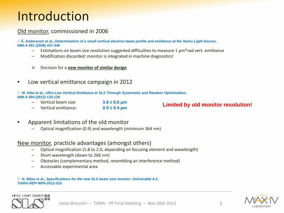
Introduction
Limited by old monitor resolution!
Old monitor, commissioned in 2006 Å. Andersson et al., Determination of a small vertical electron beam profile and emittance at the Swiss Light Source, NIM-A 591 (2008) 437-446
– Estimations on beam size resolution suggested difficulties to measure 1 pm*rad vert. emittance – Modification discarded: monitor is integrated in machine diagnostics! Decision for a new monitor of similar design
• Low vertical emittance campaign in 2012
M. Aiba et al., Ultra Low Vertical Emittance at SLS Through Systematic and Random Optimization, NIM-A 694 (2012) 133-139
– Vertical beam size: 3.6 ± 0.6 µm – Vertical emittance: 0.9 ± 0.4 pm
• Apparent limitations of the old monitor
– Optical magnification (0.9) and wavelength (minimum 364 nm) New monitor, practicle advantages (amongst others)
– Optical magnification (1.8 to 2.0, depending on focusing element and wavelength) – Short wavelength (down to 266 nm) – Obstacles (complementary method, resembling an interference method) – Accessable experimental area
N. Milas et al., Specifications for the new SLS beam size monitor: Deliverable 6.2, TIARA-REP-WP6-2012-015
3
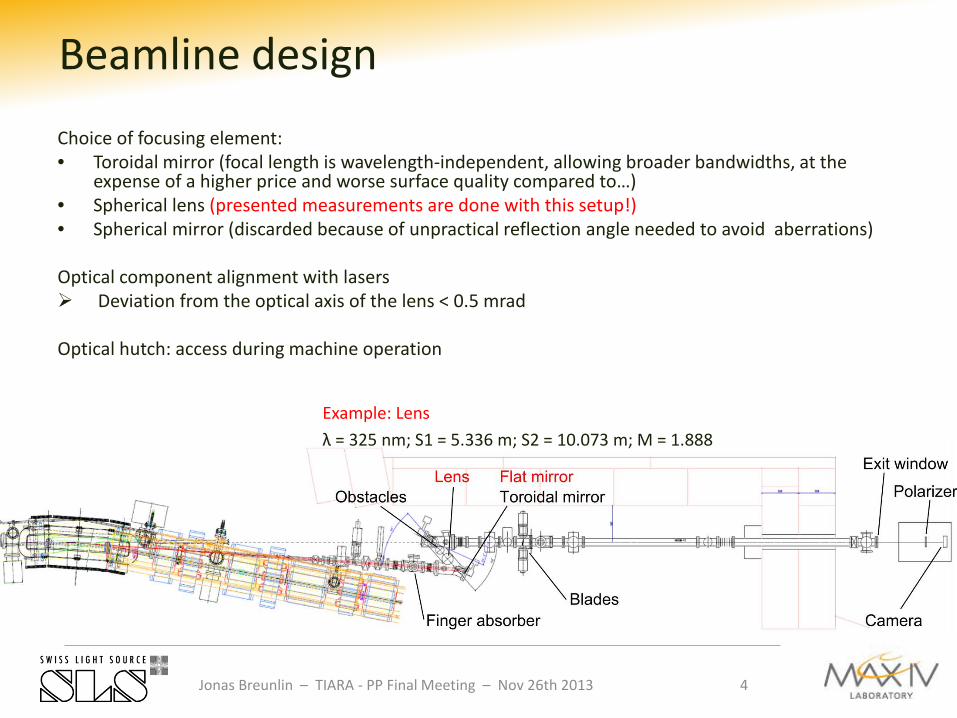
Choice of focusing element: • Toroidal mirror (focal length is wavelength-independent, allowing broader bandwidths, at the
expense of a higher price and worse surface quality compared to…) • Spherical lens (presented measurements are done with this setup!) • Spherical mirror (discarded because of unpractical reflection angle needed to avoid aberrations) Optical component alignment with lasers Deviation from the optical axis of the lens < 0.5 mrad Optical hutch: access during machine operation
Jonas Breunlin – TIARA - PP Final Meeting – Nov 26th 2013
Beamline design
Example: Lens λ = 325 nm; S1 = 5.336 m; S2 = 10.073 m; M = 1.888
4
Jonas Breunlin – TIARA - PP Final Meeting – Nov 26th 2013
Beamline design
5
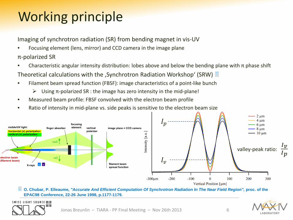
Imaging of synchrotron radiation (SR) from bending magnet in vis-UV • Focusing element (lens, mirror) and CCD camera in the image plane
π-polarized SR • Characteristic angular intensity distribution: lobes above and below the bending plane with π phase shift
Theoretical calculations with the ‚Synchrotron Radiation Workshop‘ (SRW) • Filament beam spread function (FBSF): image characteristics of a point-like bunch
Using π-polarized SR : the image has zero intensity in the mid-plane! • Measured beam profile: FBSF convolved with the electron beam profile • Ratio of intensity in mid-plane vs. side peaks is sensitive to the electron beam size
Jonas Breunlin – TIARA - PP Final Meeting – Nov 26th 2013
Working principle
𝐼𝑝
𝐼𝑣
O. Chubar, P. Elleaume, "Accurate And Efficient Computation Of Synchrotron Radiation In The Near Field Region", proc. of the EPAC98 Conference, 22-26 June 1998, p.1177-1179.
6
valley-peak ratio: 𝐼𝑣𝐼𝑝
Jonas Breunlin – TIARA - PP Final Meeting – Nov 26th 2013
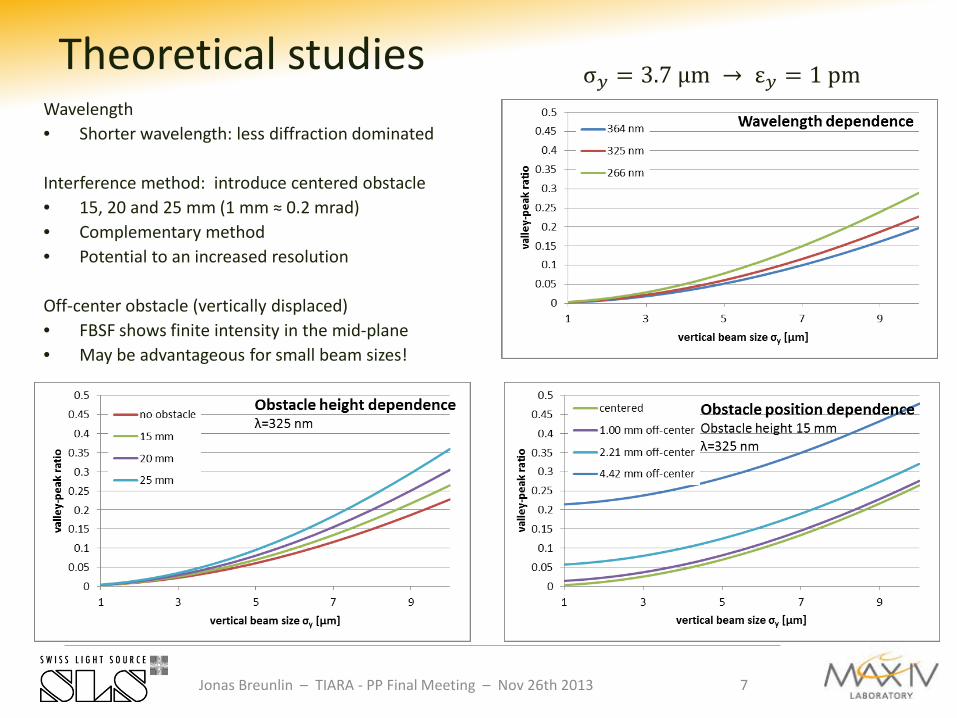
Theoretical studies Wavelength • Shorter wavelength: less diffraction dominated Interference method: introduce centered obstacle • 15, 20 and 25 mm (1 mm ≈ 0.2 mrad) • Complementary method • Potential to an increased resolution
Off-center obstacle (vertically displaced) • FBSF shows finite intensity in the mid-plane • May be advantageous for small beam sizes!
7
σ𝑦 = 3.7 µm → ε𝑦 = 1 pm
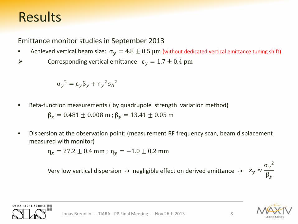
Emittance monitor studies in September 2013 • Achieved vertical beam size: σ𝑦 = 4.8 ± 0.5 µm (without dedicated vertical emittance tuning shift)
Corresponding vertical emittance: ε𝑦 = 1.7 ± 0.4 pm
• Beta-function measurements ( by quadrupole strength variation method) β𝑥 = 0.481 ± 0.008 m ; β𝑦 = 13.41 ± 0.05 m
• Dispersion at the observation point: (measurement RF frequency scan, beam displacement measured with monitor)
η𝑥 = 27.2 ± 0.4 mm ; η𝑦 = −1.0 ± 0.2 mm Very low vertical dispersion -> negligible effect on derived emittance ->
Jonas Breunlin – TIARA - PP Final Meeting – Nov 26th 2013
Results
σ𝑦2 = ε𝑦β𝑦 + η𝑦2σδ2
ε𝑦 ≈σ𝑦2
β𝑦
8
Jonas Breunlin – TIARA - PP Final Meeting – Nov 26th 2013
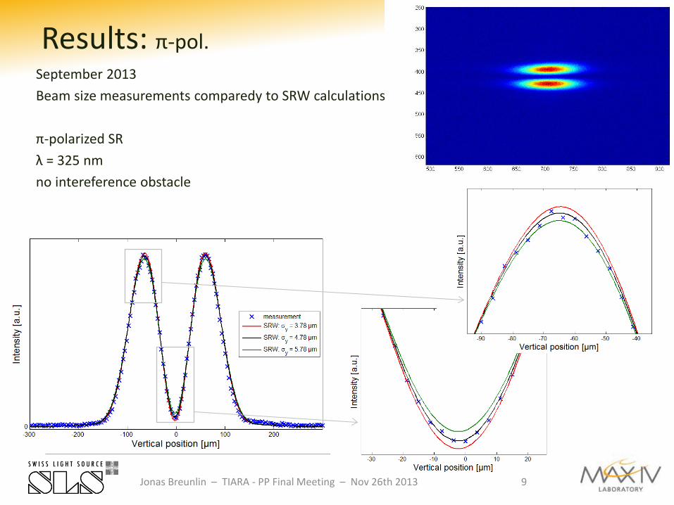
Results: π-pol. September 2013 Beam size measurements comparedy to SRW calculations π-polarized SR λ = 325 nm no intereference obstacle
9
Jonas Breunlin – TIARA - PP Final Meeting – Nov 26th 2013
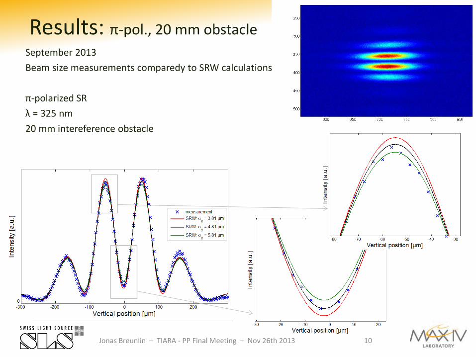
Results: π-pol., 20 mm obstacle
10
September 2013 Beam size measurements comparedy to SRW calculations π-polarized SR λ = 325 nm 20 mm intereference obstacle
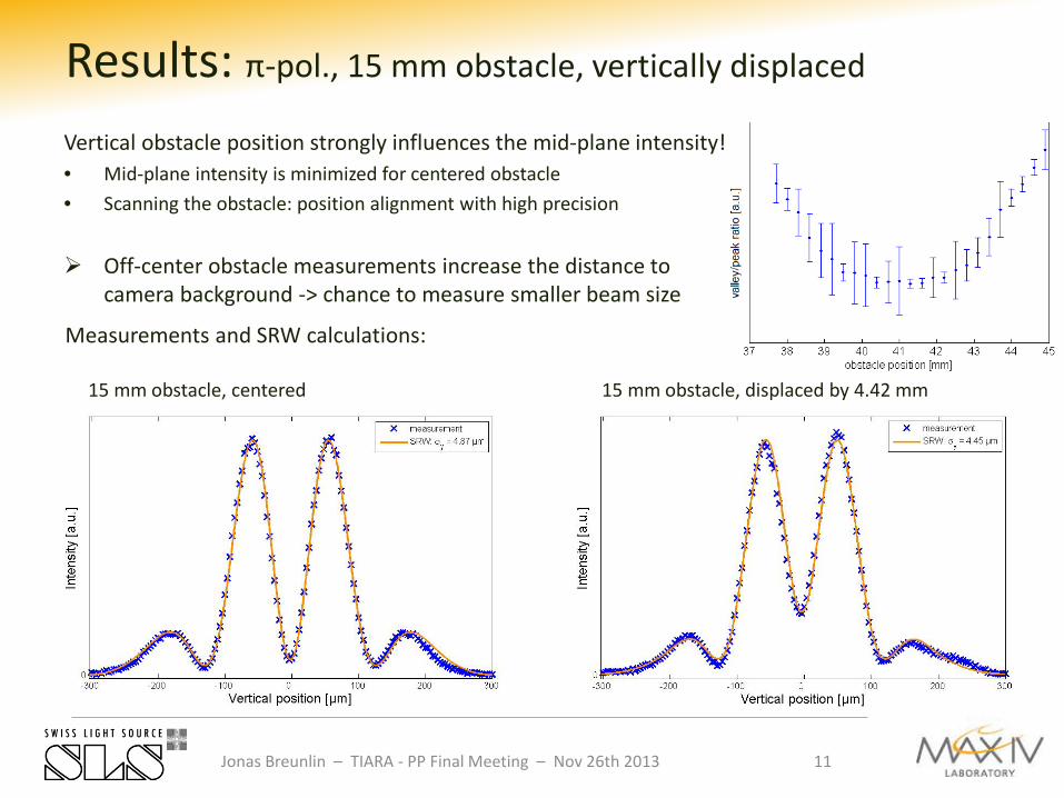
Vertical obstacle position strongly influences the mid-plane intensity! • Mid-plane intensity is minimized for centered obstacle • Scanning the obstacle: position alignment with high precision
Off-center obstacle measurements increase the distance to camera background -> chance to measure smaller beam size
Jonas Breunlin – TIARA - PP Final Meeting – Nov 26th 2013
Results: π-pol., 15 mm obstacle, vertically displaced
11
Measurements and SRW calculations: 15 mm obstacle, centered 15 mm obstacle, displaced by 4.42 mm
• „Camera odyssey 266 nm“ – 1st measurements with old camera at 266 nm, unsatisfactory Measured images show unexplained deviations from theory New camera acquired
• Spots on the exit windows
– Old and new beam size monitor – Unexplained (UV-induced crystalization of Fused Silica?) – For now: change the light path through the exit window time to time
Jonas Breunlin – TIARA - PP Final Meeting – Nov 26th 2013
Work ongoing:
12
We achieved: • Monitor beam line commissioning with lens • Measured beam with σ𝑦 = 4.8 ± 0.5 µm → ε𝑦 = 1.7 ± 0.4 pm • Beam size measurements with complementary methods in good agreement • Measured and simulated vertical beam profiles in good agreement Estimation on resolvable emittance under present monitor condition: σ𝑦 = 3.0 µm → ε𝑦 = 0.6 … 0.7 pm On the way: • Next monitor beamline studies at low ε𝑦 on Dec. 3rd • Systematic studies on monitor resolution • New UV camera for 266 nm • Toroidal mirror will be installed beginning of next year
Jonas Breunlin – TIARA - PP Final Meeting – Nov 26th 2013
Summary
13