Embed Size (px)
Citation preview
Metal casting and Welding (15ME35A)
Dept of Mechanical Engineering, ATMECE, Mysuru Page 1
Metal Casting and Welding
(15ME35A)
Metal casting and Welding (15ME35A)
Dept of Mechanical Engineering, ATMECE, Mysuru Page 2
ATME COLLEGE OF ENGINEERING
VISION
Development of academically excellent, culturally vibrant, socially responsible and globally
competent human resources.
MISSION
To keep pace with advancements in knowledge and make the students competitive
and capable at the global level.
To create an environment for the students to acquire the right physical, intellectual,
emotional and moral foundations and shine as torch bearers of tomorrow's society.
To strive to attain ever-higher benchmarks of educational excellence.
DEPARTMENT OFMECHANICAL ENGINEERING
VISION
To impart excellent technical education in mechanical engineering to develop technically
competent, morally upright and socially responsible mechanical engineering professionals.
MISSION:
To provide an ambience which impart excellent technical education in Mechanical Engineering.
To enable the students to acquire skill development, knowledge of Research and recent trends in
mechanical engineering which will engage them in lifelong learning.
To engage students in co-curricular and extra-curricular activities to impart social & ethical
values and imbibe leadership quality.
Metal casting and Welding (15ME35A)
Dept of Mechanical Engineering, ATMECE, Mysuru Page 3
PROGRAM EDUCATIONAL OBJECTIVES (PEO’S)
After successful completion of program, the graduates will be
PEO 1: Graduates will be able to have successful professional career in the allied
areas and be proficient to perceive higher education.
PEO 2: Graduates will attain the technical ability to understand the need analysis,
design, manufacturing, quality changing and analysis of the product.
PEO 3: Work effectively, ethically and socially responsible in allied fields of
mechanical engineering.
PEO 4: Work in a team to meet personal and organizational objectives and to
contribute to the development of the society in large.
PROGRAM OUTCOMES (PO’S)
The Mechanical engineering program students will attain:
PO1. Engineering knowledge: Apply the knowledge of mathematics, science, engineering
fundamentals, and an engineering specialization to the solution of complex engineering
problems
PO2. Problem analysis: Identify, formulate, research literature, and analyze complex
engineering problems reaching substantiated conclusions using first principles of
mathematics, natural sciences, and engineering sciences
PO3. Design/development of solutions: Design solutions for complex engineering
problems and design system components or processes that meet the specified needs
with appropriate consideration for the public health and safety, and the cultural,
societal, and environmental considerations
PO4. Conduct investigations of complex problems: Use research-based knowledge and
research methods including design of experiments, analysis and interpretation of data,
and synthesis of the information to provide valid conclusions
PO5. Modern tool usage: Create, select, and apply appropriate techniques, resources, and
modern engineering and IT tools including prediction and modeling to complex
engineering activities with an understanding of the limitations
PO6. The engineer and society: Apply reasoning informed by the contextual knowledge
to assess societal, health, safety, legal and cultural issues and the consequent
responsibilities relevant to the professional engineering practice
PO7. Environment and sustainability: Understand the impact of the professional
engineering solutions in societal and environmental contexts, and demonstrate the
knowledge of, and need for sustainable development
Metal casting and Welding (15ME35A)
Dept of Mechanical Engineering, ATMECE, Mysuru Page 4
PO8. Ethics: Apply ethical principles and commit to professional ethics and responsibilities and norms of the
engineering practice
PO9. Individual and team work: Function effectively as an individual, and as a member or leader in diverse
teams, and in multidisciplinary settings
PO10. Communication: Communicate effectively on complex engineering activities with the engineering
community and with society at large, such as, being able to comprehend and write effective reports and
design documentation, make effective presentations, and give and receive clear instructions
PO11. Project management and finance: Demonstrate knowledge and understanding of the engineering and
management principles and apply these to one’s own work, as a member and leader in a team, to manage
projects and in multidisciplinary environments
PO12. Life-long learning: Recognize the need for, and have the preparation and ability to engage in
independent and life-long learning in the broadest context of technological change
PROGRAM SPECIFIC OUTCOMES (PSO’S)
After successful completion of program, the graduates will be
PSO 1: To comprehend the knowledge of mechanical engineering and apply them to identify, formulate and
address the mechanical engineering problems using latest technology in a effective manner.
PSO 2: To work successfully as a mechanical engineer in team, exhibit leadership quality and provide viable
solution to industrial and societal problems.
PSO 3: To apply modern management techniques and manufacturing techniques to produce products of high
quality at optimal cost.
PSO 4: To exhibit honesty, integrity, and conduct oneself responsibly, ethically and legally, holding the safety
and welfare of the society paramount.
Metal casting and Welding (15ME35A)
Dept of Mechanical Engineering, ATMECE, Mysuru Page 5
METAL CASTING AND WELDING
[AS PER CHOICE ASED CREDIT SYSTEM (CBCS) SCHEME]
SEMESTER – III
Subject Code 15 ME 35 A IA Marks 20
Number of Lecture Hrs / Week 04 Exam Marks 80
Total Number of Lecture Hrs 50 Exam Hours 03
CREDITS – 04
COURSE OBJECTIVE
1) To provide detailed information about the moulding processes.
2) To provide knowledge of various casting process in manufacturing.
3) To impart knowledge of various joining process used in manufacturing.
4) To provide adequate knowledge of quality test methods conducted on welded and casted components.
COURSE OUTCOMES
CO
No.
Course
Outco
mes
Blooms
level
PO
CO1
Describe the casting process, preparation of Green, Core, dry sand
molds and Sweep, Shell, Investment and plaster molds.
U
PO1
CO2
Explain the Pattern, Core, Gating, Riser system and Jolt, Squeeze, Sand Slinger Molding Machines.
U
PO1
CO3 Compare the Gas fired pit, Resistance, Coreless, Electrical and Cupola Metal Furnaces.
U PO1
CO4 Compare the Gravity, Pressure die, Centrifugal, Squeeze, slush and Continuous Metal mold castings.
U PO1
CO5 Explain the Solidification process and Casting of Non-Ferrous
Metals.
U PO1
CO6 Describe the Metal Arc, TIG, MIG, Submerged and Atomic Hydrogen Welding processes used in manufacturing.
U PO1
CO7 Explain the Resistance spot, Seam, Butt , Projection, Friction, Explosive,Thermit, Laser and Electron Beam Special type of welding process used in manufacturing.
U PO1
CO8 Describe the Metallurgical aspects in Welding and inspection methods for the quality U PO1
Metal casting and Welding (15ME35A)
Dept of Mechanical Engineering, ATMECE, Mysuru Page 6
MODULE -1
INTRODUCTION & BASIC MATERIALS USED IN FOUNDRY
Introduction: Definition, Classification of manufacturing processes. Metals cast in the foundry-classification, factors that determine the selection of a casting alloy. Introduction to casting process & steps involved. Patterns: Definition, classification, materials used for pattern, various pattern allowances and their importance. Sand molding: Types of base sand, requirement of base sand. Binder, Additives definition, need
and types
Preparation of sand molds: Molding machines- Jolt type, squeeze type and Sand slinger. Study of important molding process: Green sand, core sand, dry sand, sweep mold, CO2 mold, shell mold, investment mold, plaster mold, cement bonded mold.Cores: Definition, need, types. Method of making cores, concept of gating (top, bottom, parting line, horn gate) and risering (open, blind) Functions and types
MODULE -2
MELTING & METAL MOLD CASTING METHODS
1
0 Hours
Melting furnaces: Classification of furnaces, Gas fired pit furnace, Resistance furnace, Coreless induction furnace, electric arc furnace, constructional features & working principle of cupola furnace. Casting using metal molds: Gravity die casting, pressure die casting, centrifugal casting, squeeze casting, slush casting, thixocasting, and continuous casting processes
1
0 Hours
MODULE -3
SOLIDIFICATION & NON FERROUS FOUNDRY PRACTICE
Solidification: Definition, Nucleation, solidification variables, Directional solidification-need and methods. Degasification in liquid metals-Sources of gas, degasification methods.
Fettling and cleaning of castings: Basic steps involved. Sand Casting defects- causes, features and remedies. Advantages & limitations of casting process
Nonferrous foundry practice: Aluminum castings - Advantages, limitations, melting of aluminum using lift-out type crucible furnace. Hardeners used, drossing, gas absorption, fluxing and flushing, grain refining, pouring temperature. Stir casting set up, procedure, uses, advantages and limitations.
1
0 Hours
MODULE -4
WELDING PROCESS
Welding process: Definition, Principles, Classification, Application, Advantages & limitations of welding. Arc welding: Principle, Metal arc welding (MAW), Flux Shielded Metal Arc Welding (FSMAW), Inert Gas Welding (TIG & MIG) Submerged Arc Welding (SAW) and Atomic Hydrogen Welding (AHW).
Metal casting and Welding (15ME35A)
Dept of Mechanical Engineering, ATMECE, Mysuru Page 7
Special type of welding: Resistance welding principles, Seam welding, Butt welding, Spot welding and Projection welding. Friction welding, Explosive welding, Thermit welding, Laser welding and electron beam welding.
MODULE -5
SOLDERING , BRAZING AND METALLURGICAL ASPECTS IN WELDING
1 0 Hours
Structure of welds, Formation of different zones during welding, Heat Affected Zone (HAZ), Parameters affecting HAZ. Effect of carbon content on structure and properties of steel, Shrinkage in welds& Residual stresses, Concept of electrodes, filler rod and fluxes. Welding defects- Detection, causes & remedy.
Soldering, brazing, gas welding: Soldering, Brazing, Gas Welding: Principle, oxy- Acetylene welding, oxy-hydrogen welding, air-acetylene welding, Gas cutting, powder cutting.
Inspection methods: Methods used for inspection of casting and welding. Visual, magnetic particle, fluorescent particle, ultrasonic.Radiography, eddy current, holography methods of inspection.
1 0 Hours
TEXT BOOKS:
1) “Manufacturing Process-I”, Dr.K.Radhakrishna, Sapna Book House,5th Revised Edition
2009.
2) “Manufacturing & Technology: Foundry Forming and Welding”,P.N.Rao, 3rd Ed., Tata
McGraw Hill, 2003.
REFERENCE BOOKS:
• “Process and Materials of Manufacturing”, Roy A Lindberg, 4th Ed.Pearson Edu.
2006.
• “Manufacturing Technology”, SeropeKalpakjian, Steuen. R. Sechmid,Pearson
Education Asia, 5th Ed. 2006.
• “Principles of metal casting”, Rechard W. Heine, Carl R. LoperJr.,Philip C. Rosenthal, Tata McGraw Hill Education Private Limited Ed.1976.
Question paper pattern:
1) The question paper will have ten questions.
2) Each full question consisting of 16 marks.
3) There will be 2 full questions (with a maximum of 4 sub questions) from each module.
4) Each full question will have sub questions covering all the topics under a module.
The students will have to answer 5 full questions, selecting one full question from each module.
Metal casting and Welding (15ME35A)
Dept of Mechanical Engineering, ATMECE, Mysuru Page 8
MODULE -1 INTRODUCTION & BASIC MATERIALS USED IN FOUNDRY
CONTENTS:
1. Classification of manufacturing processes
2. Basic Manufacturing Processes
3. Patterns
4. Additives
5. Molding Material and Properties
6. No-bake sand molds
7. Investment molding
Course Objectives:
1. To understand different types of manufacturing processes with their comparison.
2. To get enrich with knowledge of casting process and its types, parameters.
3. To understand different types of moulding sand available for cavity preparation.
What is “Manufacturing”?
The English word manufacture is several centuries old. The term manufacture comes from two
Latin words, manus (hand) and factus (make). As per oxford English dictionary manufacture
refers “to make or produce goods in large quantities, using machinery”.
Working definition of manufacturing
There are two types of working definitions available for manufacturing: as a technical process
and as an economic process.
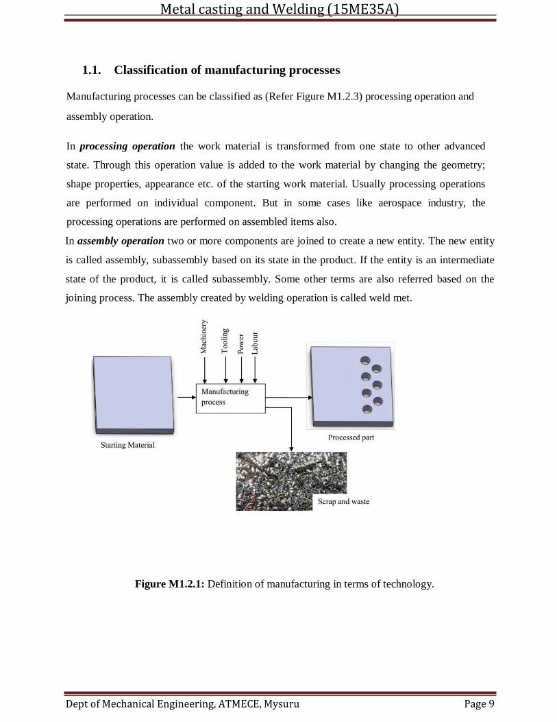
Technologically: Manufacturing is the application of physical and chemical processes to alter
the geometry, properties and or appearance of a given starting material to make parts or product
as shown in Figure M1.2.1.
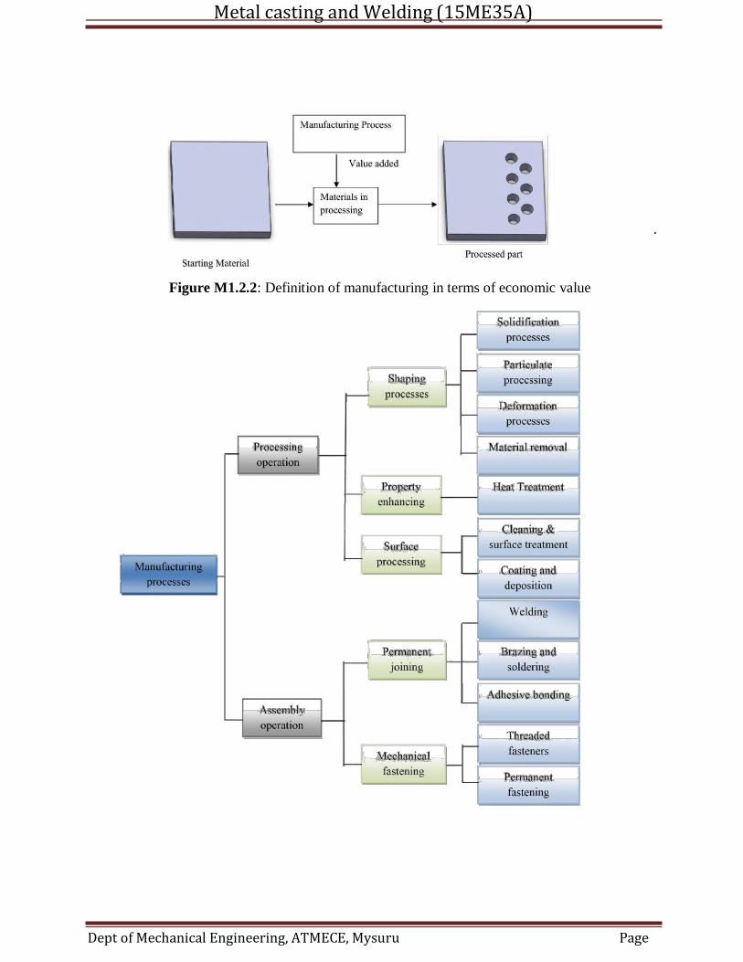
Economically: Manufacturing is the transformation of materials into items of greater value by
means of one or more process and or assembly operation as shown in Figure M1.2.2.
Metal casting and Welding (15ME35A)
Dept of Mechanical Engineering, ATMECE, Mysuru Page 9
1.1. Classification of manufacturing processes
Manufacturing processes can be classified as (Refer Figure M1.2.3) processing operation and
assembly operation.
In processing operation the work material is transformed from one state to other advanced
state. Through this operation value is added to the work material by changing the geometry;
shape properties, appearance etc. of the starting work material. Usually processing operations
are performed on individual component. But in some cases like aerospace industry, the
processing operations are performed on assembled items also.
In assembly operation two or more components are joined to create a new entity. The new entity
is called assembly, subassembly based on its state in the product. If the entity is an intermediate
state of the product, it is called subassembly. Some other terms are also referred based on the
joining process. The assembly created by welding operation is called weld met.
Figure M1.2.1: Definition of manufacturing in terms of technology.
Metal casting and Welding (15ME35A)
Dept of Mechanical Engineering, ATMECE, Mysuru Page 10
.
Figure M1.2.2: Definition of manufacturing in terms of economic value
Metal casting and Welding (15ME35A)
Dept of Mechanical Engineering, ATMECE, Mysuru Page 8
Job and Station
In classical manufacturing, a job is defined as the total work or duties a worker performs. A
station is a location or area where a production worker performs tasks and jobs. A job at an
assembly station may consist of the following tasks:
5) Attach carburetor
6) Connect gas line
7) Connect vacuum line
8) Connect accelerator rod.
Jobs and stations are now applied to unmanned machines also. A simple machine may have only
station. A complex machine may have multiple stations.
Operation
An operation is a distinct action performed to produce a desired result. Operations can be
3) Materials handling and transporting
4) Processing
5) Packaging
6) Inspecting and testing
7) Storing
Treatments
Treatments operate continually on the work piece. These modify the product in process without
tool contact. Some examples include heat treating, curing, galvanizing, plating, finishing,
(chemical) cleaning and painting. These are often done in large tanks or furnaces or rooms, away
from workers as they can be harmful.
1.2. Basic Manufacturing Processes
It is described as the manufacturing processes which create or add value to a product. The
manufacturing processes can be classified as:
Metal casting and Welding (15ME35A)
Dept of Mechanical Engineering, ATMECE, Mysuru Page 9
• Casting, foundry, or moulding processes
• Forming or metalworking processes
• Machining (material removal) processes
• Joining and assembly
• Surface treatments (finishing)
• Rapid prototyping
• Heat treating
• Other
Other manufacturing operations include inspection, testing, transportation, automated material
handling and even packaging. In casting, the metal is heated sufficiently to make it into liquid and
then poured into moulds of desired shapes. Various machining operations are turning, drilling and
milling. Joining processes include welding, soldering, brazing and adhesive bonding. The process
of heat treating is carried out to enhance various properties and include annealing and
strengthening processes for metals and glasses. Surface processing includes cleaning, coating and
thin film deposition, electroplating, anodising etc.
Product Life cycle and life cycle cost
Manufacturing systems are dynamic and liable to change over time. Thus there is a traditional
relation between a product's life cycle and the kind of manufacturing system used to make it. The
life cycle consists of the following steps:
5) Start-up: new product or new company, low volumes
6) Rapid growth: product becomes standardized in the market, higher volumes
7) Maturation: designs become standard, process development becomes important
8) Commodity: long life, standard of the industry type of product
9) Decline: product replaced by improved products.
Manufacturing System Design
A manufacturing system must consider two customers namely, the external that buys that the
product and the internal that makes the product. The external customer may be global in scope,
but the internal customer is critical in determining the design and manufacturing stages.
Metal casting and Welding (15ME35A)
Dept of Mechanical Engineering, ATMECE, Mysuru Page 10
The complexity of the manufacturing system design where choices of system design trade off with
parts variety.
Summary
Manufacturing becomes successful by understanding how the system works, how goods are
controlled, the decision making at the correct level. Engineers must possess a broad fundamental
knowledge of design, metallurgy, processing, economics, accounting and human relations.
1.3. PATTERNS
A pattern is a replica of the object to be cast, used to prepare the cavity into which molten
material will be poured during the casting process.
Typically, materials used for pattern making are wood, metal or plastics. Wax and plaster of
paris are also used, but only for specialized applications. Mahogany is the most commonly used
material for patterns, primarily because it is soft, light, and easy to work, but also once properly
cured it is about as stable as any wood available, not subject to warping or curling. Once the pattern
is built the foundry does not want it changing shape. The downside is that it wears out fast, and is
prone to moisture attack. Metal patterns are more long lasting, and do not succumb to moisture, but
they are heavier and difficult to repair once damaged.
Wax patterns are used in a casting process called investment casting. A combination of paraffin
wax, bees wax and carnauba wax is used for this purpose.[ Plaster of paris is usually used in making
master dies and molds, as it gains hardness quickly, with a lot of flexibility when in the setting stage
Functions of the Pattern
1. A pattern prepares a mold cavity for the purpose of making a casting.
2. A pattern may contain projections known as core prints if the casting requires a core and
need to be made hollow.
3. Runner, gates, and risers used for feeding molten metal in the mold cavity may form a part
of the pattern.
4. Patterns properly made and having finished and smooth surfaces reduce casting defects.
5. A properly constructed pattern minimizes the overall cost of the castings.
Metal casting and Welding (15ME35A)
Dept of Mechanical Engineering, ATMECE, Mysuru Page 11
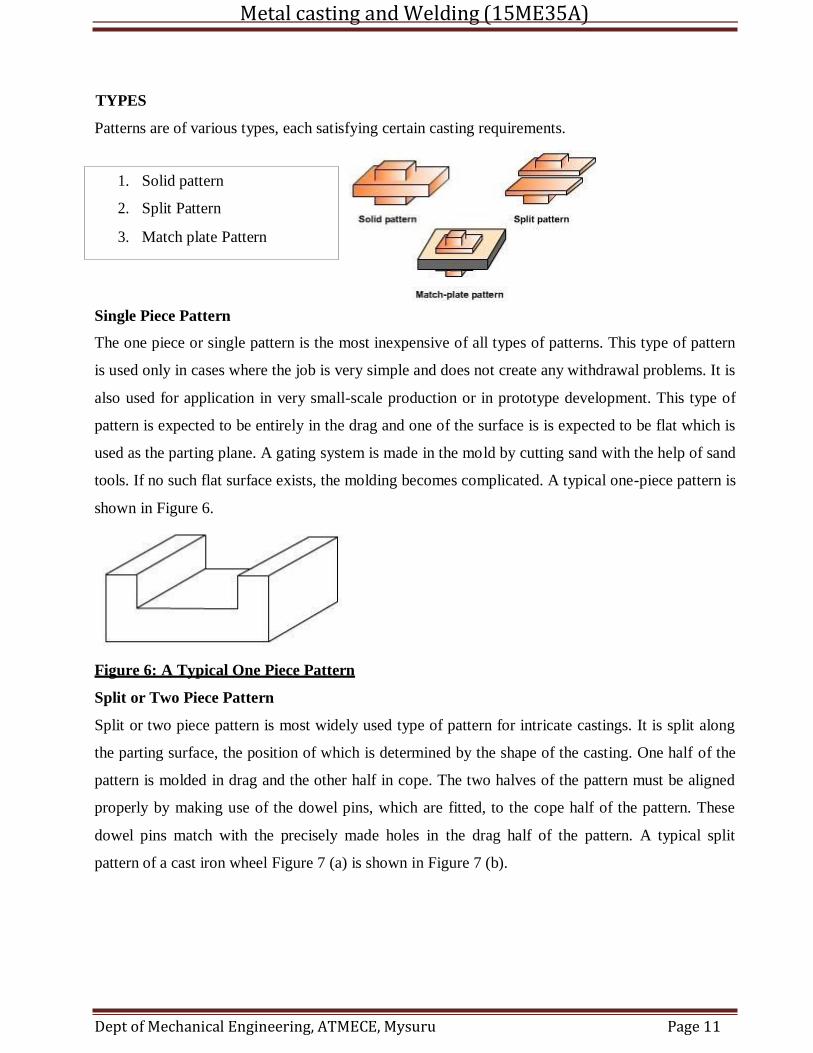
TYPES
Patterns are of various types, each satisfying certain casting requirements.
Single Piece Pattern
The one piece or single pattern is the most inexpensive of all types of patterns. This type of pattern
is used only in cases where the job is very simple and does not create any withdrawal problems. It is
also used for application in very small-scale production or in prototype development. This type of
pattern is expected to be entirely in the drag and one of the surface is is expected to be flat which is
used as the parting plane. A gating system is made in the mold by cutting sand with the help of sand
tools. If no such flat surface exists, the molding becomes complicated. A typical one-piece pattern is
shown in Figure 6.
Figure 6: A Typical One Piece Pattern
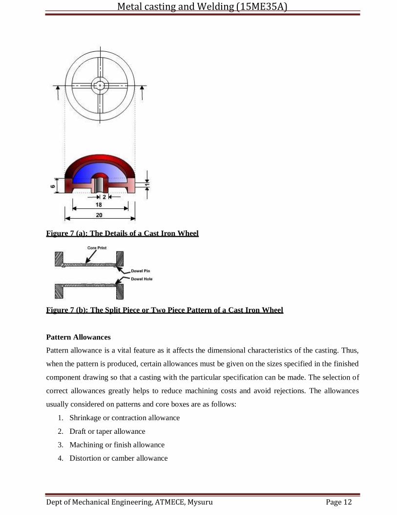
Split or Two Piece Pattern
Split or two piece pattern is most widely used type of pattern for intricate castings. It is split along
the parting surface, the position of which is determined by the shape of the casting. One half of the
pattern is molded in drag and the other half in cope. The two halves of the pattern must be aligned
properly by making use of the dowel pins, which are fitted, to the cope half of the pattern. These
dowel pins match with the precisely made holes in the drag half of the pattern. A typical split
pattern of a cast iron wheel Figure 7 (a) is shown in Figure 7 (b).
1. Solid pattern
2. Split Pattern
3. Match plate Pattern
Metal casting and Welding (15ME35A)
Dept of Mechanical Engineering, ATMECE, Mysuru Page 12
Figure 7 (a): The Details of a Cast Iron Wheel
Figure 7 (b): The Split Piece or Two Piece Pattern of a Cast Iron Wheel
Pattern Allowances
Pattern allowance is a vital feature as it affects the dimensional characteristics of the casting. Thus,
when the pattern is produced, certain allowances must be given on the sizes specified in the finished
component drawing so that a casting with the particular specification can be made. The selection of
correct allowances greatly helps to reduce machining costs and avoid rejections. The allowances
usually considered on patterns and core boxes are as follows:
1. Shrinkage or contraction allowance
2. Draft or taper allowance
3. Machining or finish allowance
4. Distortion or camber allowance
Metal casting and Welding (15ME35A)
Dept of Mechanical Engineering, ATMECE, Mysuru Page 13
5. Rapping allowance
Shrinkage or Contraction Allowance ( click on Table 1 to view various rate of contraction of
various materials)
All most all cast metals shrink or contract volumetrically on cooling. The metal shrinkage is of two
types:
i. Liquid Shrinkage: it refers to the reduction in volume when the metal changes from liquid
state to solid state at the solidus temperature. To account for this shrinkage; riser,
which feed the liquid metal to the casting, are provided in the mold.
ii. Solid Shrinkage: it refers to the reduction in volume caused when metal loses temperature
in solid state. To account for this, shrinkage allowance is provided on the patterns.
Draft or Taper Allowance
By draft is meant the taper provided by the pattern maker on all vertical surfaces of the
pattern so that it can be removed from the sand without tearing away the sides of the sand
mold and without excessive rapping by the molder. Figure 3 (a) shows a pattern having no
draft allowance being removed from the pattern. In this case, till the pattern is completely
lifted out, its sides will remain in contact with the walls of the mold, thus tending to break
it. Figure 3 (b) is an illustration of a pattern having proper draft allowance. Here, the
moment the pattern lifting commences, all of its surfaces are well away from the sand
surface. Thus the pattern can be removed without damaging the mold cavity.
Machining or Finish Allowance
The finish and accuracy achieved in sand casting are generally poor and therefore when the
casting is functionally required to be of good surface finish or dimensionally accurate, it is
generally achieved by subsequent machining. Machining or finish allowances are therefore
added in the pattern dimension. The amount of machining allowance to be provided for is
affected by the method of molding and casting used viz. hand molding or machine molding,
sand casting or metal mold casting. The amount of machining allowance is also affected by
the size and shape of the casting; the casting orientation; the metal; and the degree of
accuracy and finish required.
Metal casting and Welding (15ME35A)
Dept of Mechanical Engineering, ATMECE, Mysuru Page 14
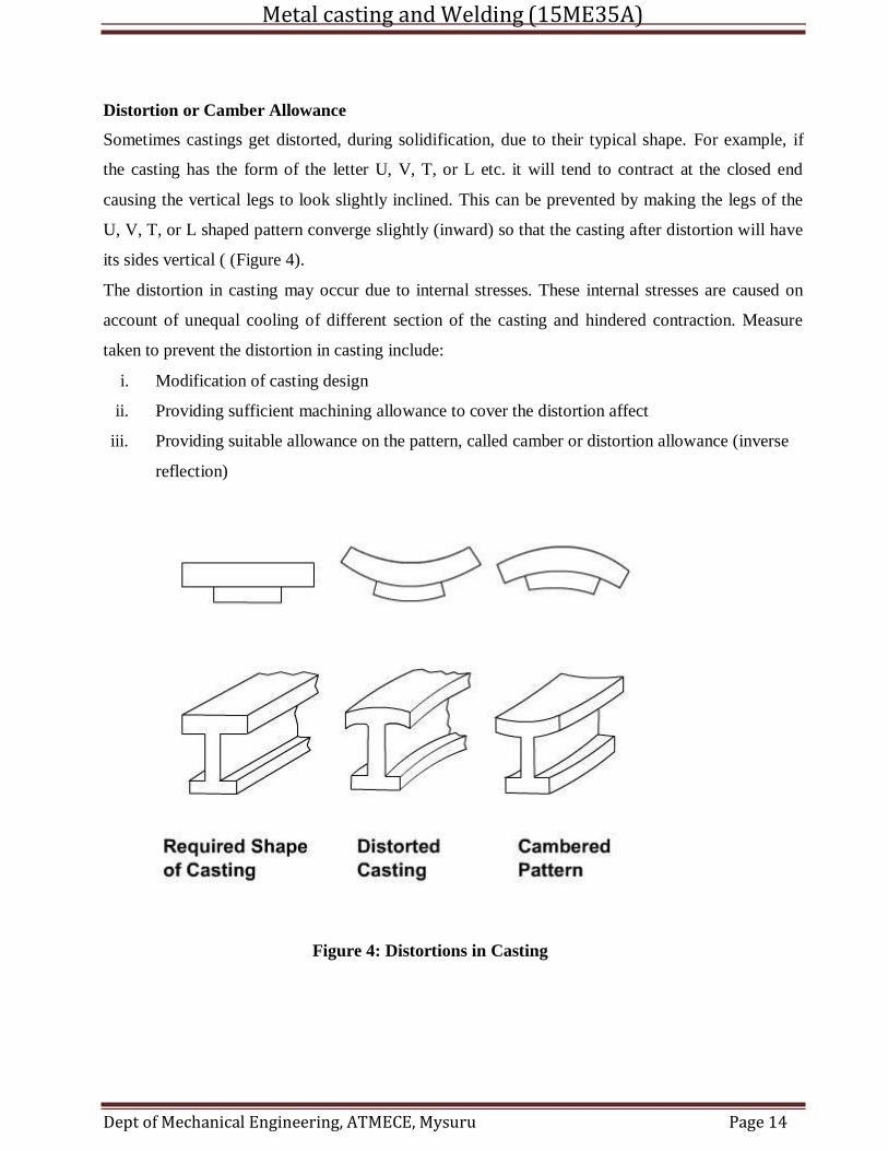
Distortion or Camber Allowance
Sometimes castings get distorted, during solidification, due to their typical shape. For example, if
the casting has the form of the letter U, V, T, or L etc. it will tend to contract at the closed end
causing the vertical legs to look slightly inclined. This can be prevented by making the legs of the
U, V, T, or L shaped pattern converge slightly (inward) so that the casting after distortion will have
its sides vertical ( (Figure 4).
The distortion in casting may occur due to internal stresses. These internal stresses are caused on
account of unequal cooling of different section of the casting and hindered contraction. Measure
taken to prevent the distortion in casting include:
i. Modification of casting design
ii. Providing sufficient machining allowance to cover the distortion affect
iii. Providing suitable allowance on the pattern, called camber or distortion allowance (inverse
reflection)
Figure 4: Distortions in Casting
Metal casting and Welding (15ME35A)
Dept of Mechanical Engineering, ATMECE, Mysuru Page 15
1.4. BINDER: Binders are added to a base sand to bond the sand particle together (i.e. it is
the glue that holds the mold together)
Clay and water
A mixture of clay and water is the most commonly used binder. There are two types of clay
commonly used: bentonite andkaolinite, with the former being the most common
Oil
Oils, such as linseed oil, other vegetable oils and marine oils, used to be used as a binder, however
due to their increasing cost, they have been mostly phased out. The oil also required careful baking
at 100 to 200 °C (212 to 392 °F) to cure (if overheated, the oil becomes brittle, wasting the mold)
Resin
Resin binders are natural or synthetic high melting point gums. The two common types used
are urea formaldehyde (UF) and phenol formaldehyde (PF) resins. PF resins have a higher heat
resistance than UF resins and cost less. There are also cold-set resins, which use a catalyst instead
of a heat to cure the binder. Resin binders are quite popular because different properties can be
achieved by mixing with various additives. Other advantages include good collapsibility, low
gassing, and they leave a good surface finish on the casting.
MDI (methylene diphenyl diisocyanate) is also a commonly used binder resin in the foundry core
process.
Sodium silicate
Sodium silicate [Na2SiO3 or (Na2O)(SiO2)] is a high strength binder used with silica molding sand.
To cure the binder,carbon dioxide gas is used, which creates the following reaction:
The advantage to this binder is that it can be used at room temperature and is fast. The disadvantage
is that its high strength leads to shakeout difficulties and possibly hot tears in the casting.
1.5. Additives
Additives are added to the molding components to improve: surface finish, dry strength,
refractoriness, and "cushioning properties
Up to 5% of reducing agents, such as coal powder, pitch, creosote, and fuel oil, may be added to the
molding material to prevent wetting (prevention of liquid metal sticking to sand particles, thus
leaving them on the casting surface), improve surface finish, decrease metal penetration, and burn-
Metal casting and Welding (15ME35A)
Dept of Mechanical Engineering, ATMECE, Mysuru Page 16
on defects. These additives achieve this by creating gases at the surface of the mold cavity, which
prevent the liquid metal from adhering to the sand. Reducing agents are not used with steel casting,
because they can carburize the metal during casting.
Up to 3% of "cushioning material", such as wood flour, saw dust, powdered husks, peat, and straw,
can be added to reducescabbing, hot tear, and hot crack casting defects when casting high
temperature metals. These materials are beneficial because burn-off when the metal is poured
creates tiny voids in the mold, allowing the sand particles to expand. They also increase
collapsibility and reduce shakeout time.
Up to 2% of cereal binders, such as dextrin, starch, sulphite lye, and molasses, can be used to
increase dry strength (the strength of the mold after curing) and improve surface finish. Cereal
binders also improve collapsibility and reduce shakeout time because they burn off when the metal
is poured. The disadvantage to cereal binders is that they are expensive.
Up to 2% of iron oxide powder can be used to prevent mold cracking and metal penetration,
essentially improving refractoriness. Silica flour (fine silica) and zircon flour also improve
refractoriness, especially in ferrous castings. The disadvantages to these additives is that they
greatly reduce permeability.
Metal casting and Welding (15ME35A)
Dept of Mechanical Engineering, ATMECE, Mysuru Page 17
1.6. Molding Material and Properties
A large variety of molding materials is used in foundries for manufacturing molds and cores.
They include molding sand, system sand or backing sand, facing sand, parting sand, and core
sand. The choice of molding materials is based on their processing properties. The properties that
are generally required in molding materials are:
Refractoriness
It is the ability of the molding material to resist the temperature of the liquid metal to be poured
so that it does not get fused with the metal. The refractoriness of the silica sand is highest.
Permeability
During pouring and subsequent solidification of a casting, a large amount of gases and steam is
generated. These gases are those that have been absorbed by the metal during melting, air
absorbed from the atmosphere and the steam generated by the molding and core sand. If these
gases are not allowed to escape from the mold, they would be entrapped inside the casting and
cause casting defects. To overcome this problem the molding material must be porous. Proper
venting of the mold also helps in escaping the gases that are generated inside the mold cavity.
Green Strength
The molding sand that contains moisture is termed as green sand. The green sand particles must
have the ability to cling to each other to impart sufficient strength to the mold. The green sand
must have enough strength so that the constructed mold retains its shape.
Dry Strength
When the molten metal is poured in the mold, the sand around the mold cavity is quickly
converted into dry sand as the moisture in the sand evaporates due to the heat of the molten
metal. At this stage the molding sand must posses the sufficient strength to retain the exact shape
of the mold cavity and at the same time it must be able to withstand the metallostatic pressure of
the liquid material.
Hot Strength
As soon as the moisture is eliminated, the sand would reach at a high temperature when the metal
in the mold is still in liquid state. The strength of the sand that is required to hold the shape of the
cavity is called hot strength.
Metal casting and Welding (15ME35A)
Dept of Mechanical Engineering, ATMECE, Mysuru Page 18
Collapsibility
The molding sand should also have collapsibility so that during the contraction of the solidified
casting it does not provide any resistance, which may result in cracks in the castings.Besides
these specific properties the molding material should be cheap, reusable and should have good
thermal conductivity.
Molding Sand Composition
The main ingredients of any molding sand are:
Base sand,
Binder, and
Moisture
Base Sand
Silica sand is most commonly used base sand. Other base sands that are also used for making
mold are zircon sand, Chromite sand, and olivine sand. Silica sand is cheapest among all types of
base sand and it is easily available.
Binder
Binders are of many types such as:
1. Clay binders,
2. Organic binders and
3. Inorganic binders
Clay binders are most commonly used binding agents mixed with the molding sands to provide
the strength. The most popular clay types are:
Kaolinite or fire clay (Al2O3 2 SiO2 2 H2O) and Bentonite (Al2O3 4 SiO2 nH2O)
Of the two the Bentonite can absorb more water which increases its bonding power.
Moisture
Clay acquires its bonding action only in the presence of the required amount of moisture. When
water is added to clay, it penetrates the mixture and forms a microfilm, which coats the surface
of each flake of the clay. The amount of water used should be properly controlled. This is
because a part of the water, which coats the surface of the clay flakes, helps in bonding, while
the remainder helps in improving the plasticity. A typical composition of molding sand is given
in (Table 4).
Metal casting and Welding (15ME35A)
Dept of Mechanical Engineering, ATMECE, Mysuru Page 19
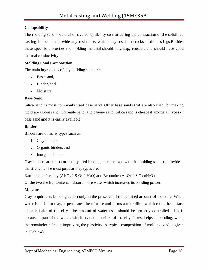
Table 4 : A Typical Composition of Molding Sand
Molding Sand Constituent Weight Percent
Silica sand 92
Clay (Sodium Bentonite) 8
Water 4
Dry Sand Molding
When it is desired that the gas forming materials are lowered in the molds, air-dried molds are
sometimes preferred to green sand molds. Two types of drying of molds are often required.
1. Skin drying and
2. Complete mold drying.
In skin drying a firm mold face is produced. Shakeout of the mold is almost as good as that
obtained with green sand molding.The most common method of drying the refractory mold
coating uses hot air, gas or oil flame. Skin drying of the mold can be accomplished with the aid
of torches, directed at the mold surface.
A core is a device used in casting and moulding processes to produce internal cavities
and reentrant angles. The core is normally a disposable item that is destroyed to get it out of the
piece.
Materials required to make core
core sand
bentonite clay
pulverized coal
water
Types
There are many types of cores available. The selection of the correct type of core depends on
production quantity, production rate, required precision, required surface finish, and the type of
metal being used. For example, certain metals are sensitive to gases that are given off by certain
Metal casting and Welding (15ME35A)
Dept of Mechanical Engineering, ATMECE, Mysuru Page 20
types of core sands; other metals have too low of a melting point to properly break down the
binder for removal during the shakeout.
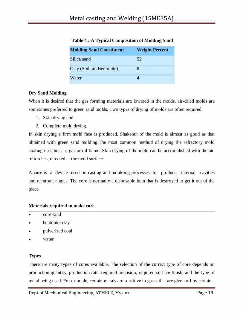
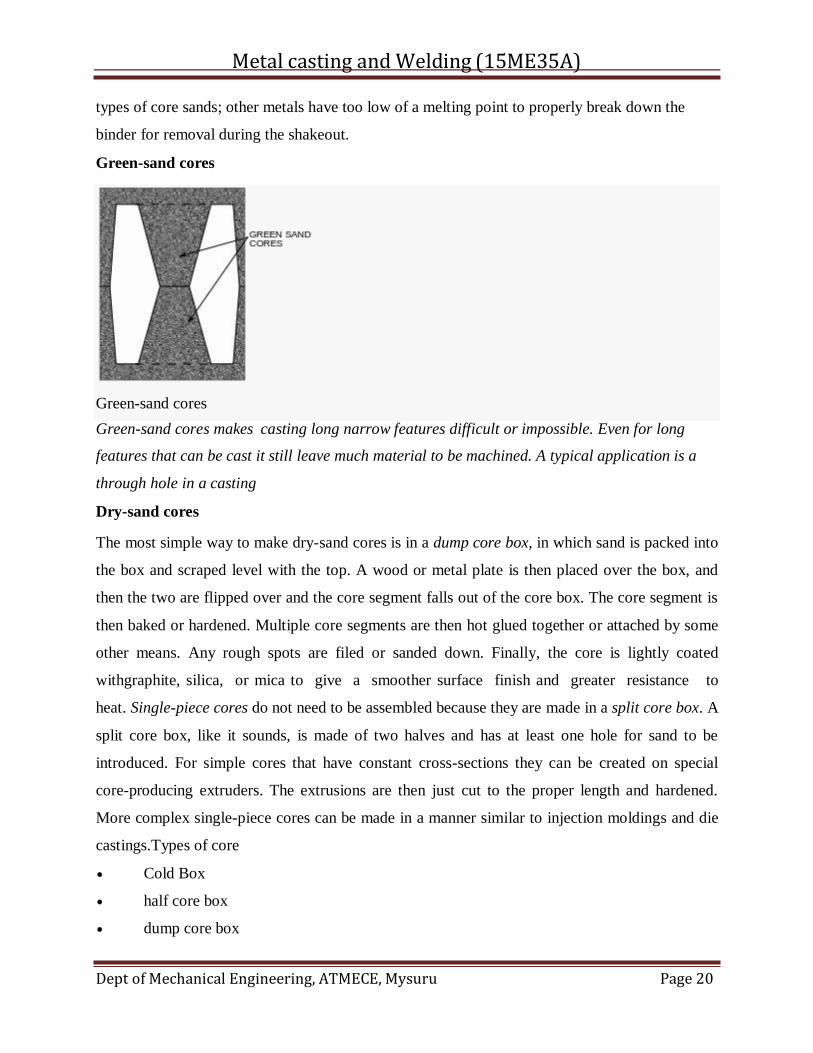
Green-sand cores
Green-sand cores makes casting long narrow features difficult or impossible. Even for long
features that can be cast it still leave much material to be machined. A typical application is a
through hole in a casting
Dry-sand cores
The most simple way to make dry-sand cores is in a dump core box, in which sand is packed into
the box and scraped level with the top. A wood or metal plate is then placed over the box, and
then the two are flipped over and the core segment falls out of the core box. The core segment is
then baked or hardened. Multiple core segments are then hot glued together or attached by some
other means. Any rough spots are filed or sanded down. Finally, the core is lightly coated
withgraphite, silica, or mica to give a smoother surface finish and greater resistance to
heat. Single-piece cores do not need to be assembled because they are made in a split core box. A
split core box, like it sounds, is made of two halves and has at least one hole for sand to be
introduced. For simple cores that have constant cross-sections they can be created on special
core-producing extruders. The extrusions are then just cut to the proper length and hardened.
More complex single-piece cores can be made in a manner similar to injection moldings and die
castings.Types of core
Cold Box
half core box
dump core box
Green-sand cores
Metal casting and Welding (15ME35A)
Dept of Mechanical Engineering, ATMECE, Mysuru Page 21
split core box
left and right core box
gang core box
strickle core box
loose piece core box
Lost cores
Core are used for complex injection moldings in the fusible core injection molding process. First,
a core is made from afusible alloy or low melting temperature polymer. It is then placed inside
the injection mold's dies and the plastic is shot into the mold. The molding is then removed from
the mold with the core still in it. Finally, the core is melted or washed out of the molding in a hot
bath.
Binders
Special binders are introduced into core sands to add strength. The oldest binder was vegetable
oil, however now synthetic oil is used, in conjunction with cereal or clay. The core is then baked
in a convection oven between 200 and 250 °C (392 and 482 °F). The heat causes the binder
to cross-link or polymerize. While this process is simple, the dimensional accuracy is low.
Another type of binder process is called the hot-box process, which uses
a thermoset and catalyst for a binder. The sand with the binder is packed into a core box that is
heated to approximately 230 °C (446 °F) (which is where the name originated from). The binder
that touches the hot surface of the core box begins to cure within 10 to 30 seconds. Depending on
the type of binder it may require further baking to fully cure.[4] Cores produced using this method
are sometimes referred to as "shell-core" because often, only the outside layer of the core is
hardened when in contact with the hot corebox. When the corebox is opened and the core
removed, the uncured sand inside the core is dumped out to be reused. This practice can also be
observed in some cold-box coremaking practices, though cold box shell-core making is much
less common.
In a similar vein, the cold-box process uses a binder that is hardened through the use of special
gases. The binder coated sand is packed into a core box and then sealed so that a curing gas can
be introduced. These gases are often toxic (i.e.amine gas) or odorous (i.e. SO2), so special
handling systems must be used. However, because high temperatures are not required the core
Metal casting and Welding (15ME35A)
Dept of Mechanical Engineering, ATMECE, Mysuru Page 22
box can be made from metal, wood, or plastic. An added benefit is that hollow core can be
formed if the gas is introduced via holes in the core surface which cause only the surface of the
core to harden; the remaining sand is then just dumped out to be used again.[4] For example, a
cold-box sand casting core binder is sodium silicate which hardens on exposure to carbon
dioxide.
Special binders are used in air-set sands to produce core at room temperature. These sands do
not require a gas catalyst because organic binders and a curing catalyst are mixed together in the
sand which initiates the curing process. The only disadvantage with this is that after the catalyst
is mixed in there is a short time to use the sand. A third way to produce room temperature cores
is by shell molding.
1.7. Gating System
The assembly of channels which facilitates the molten metal to enter into the mold cavity is
called the gating system Alternatively, the gating system refers to all passage ways through
which molten metal passes to enter into the mold cavity. The nomenclature of gating system
depends upon the function of different channels which they perform.
Down gates or sprue
Cross gates or runners
Ingates or gates
The metal flows down from the pouring basin or pouring cup into the down gate or sprue and
passes through the cross gate or channels and ingates or gates before entering into the mold
cavity.
Goals of Gating System
The goals for the gating system are
To minimize turbulence to avoid trapping gasses into the mold
To get enough metal into the mold cavity before the metal starts to solidify
To avoid shrinkage
Establish the best possible temperature gradient in the solidifying casting so that the
shrinkage if occurs must be in the gating system not in the required cast part.
Incorporates a system for trapping the non-metallic inclusions
Metal casting and Welding (15ME35A)
Dept of Mechanical Engineering, ATMECE, Mysuru Page 23
Procedure :
The main elements needed for the gating system are as follows:
Pouring basin or bush.
Sprue or downspure.
Sprue Well
Runner
Ingate
Ladle
Slag trap or filter.
The characteristics of each element are mentioned below:
Pouring basin : This is otherwise called as bush or cup. It is circular or rectangular in
shape. It collects the molten metal, which is poured, from the ladle.
Sprue : It is circular in cross section. It leads the molten metal from the pouring basin to
the sprue well.
Sprue Well : It changes the direction of flow of the molten metal to right angle and
passes it to the runner.
Runner : The runner takes the molten metal from sprue to the casting. Ingate: This is the
final stage where the molten metal moves from the runner to the mold cavity.
Slag trap : It filters the slag when the molten metal moves from the runner and ingate. It
is also placed in the runner.
Types of Gating Systems :
The gating system also depends on the direction of the parting plane, which contains the sprue,
runner and the ingate. They are as follows:
Metal casting and Welding (15ME35A)
Dept of Mechanical Engineering, ATMECE, Mysuru Page 24
Horizontal Gating System : This is used most widely. This type is normally applied in ferrous
metal's sand casting and gravity die-casting of non-ferrous metals. They are used for flat casting,
which are filled under gravity.
Vertical Gating System : This is applied in tall castings were high-pressure sand mold, shell
mold and die-casting processes are done. Top Gating System : this is applied in places where the
hot metal is poured form the top of the casting. It helps directional solidification of the casting
from top to bottom. It suits only flat castings to limit the damage of the metal during the initial
filling.
Bottom Gating System : it is used in tall castings where the molten metal enters the casting
through the bottom.
Middle Gating System : It has the characteristics of both the top and bottom.
Riser
Riser is a source of extra metal which flows from riser to mold cavity to compensate for
shrinkage which takes place in the casting when it starts solidifying. Without a riser heavier parts
of the casting will have shrinkage defects, either on the surface or internally.
Risers are known by different names as metal reservoir, feeders, or headers.
Shrinkage in a mold, from the time of pouring to final casting, occurs in three stages.
1. during the liquid state
2. during the transformation from liquid to solid
3. during the solid state
First type of shrinkage is being compensated by the feeders or the gating system. For the second
type of shrinkage risers are required. Risers are normally placed at that portion of the casting
which is last to freeze. A riser must stay in liquid state at least as long as the casting and must be
able to feed the casting during this time.
Functions of Risers
Provide extra metal to compensate for the volumetric shrinkage
Allow mold gases to escape
Metal casting and Welding (15ME35A)
Dept of Mechanical Engineering, ATMECE, Mysuru Page 25
Provide extra metal pressure on the solidifying mold to reproduce mold details more
exact.
Design Requirements of Risers
1. Riser size: For a sound casting riser must be last to freeze. The ratio of (volume / surface
area)2 of the riser must be greater than that of the casting. However, when this condition
does not meet the metal in the riser can be kept in liquid state by heating it externally or
using exothermic materials in the risers.
2. Riser placement: the spacing of risers in the casting must be considered by effectively
calculating the feeding distance of the risers.
3. Riser shape: cylindrical risers are recommended for most of the castings as spherical
risers, although considers as best, are difficult to cast. To increase volume/surface area
ratio the bottom of the riser can be shaped as hemisphere.
Fettling is the means by which a crude casting is turned into a cost effective quality
component that meets all the standards required by the customer. • In context with the casting
process, fettling means the removal of unwanted metal, e.g. Flashings, risers etc. • It can
include processes like chipping, grinding, shot blasting etc. Fettling process • It involves the
removal of the cores, gates, sprues, runners, risers and chipping of any of unnecessary
projections on the surface of the castings. Fettling operations can be divided into different
stages fettling operations Knocking dry sand cores Removal of gates & riser Removal of fins
and unwanted projections. Knocking of dry sand core Knocking out of dry sand cores. Dry
sand cores may be removed by knocking with iron bar. For quick knocking pneumatic or
hydraulic devices are employed, this method is used for small, medium work. For large
castings the hydro blast process is mostly employed. Removal of gate and RISER With
chipping hammer By using cutting saw Flame cutting With abrasive cut off machine. By
using chipping hammer It is particularly suited in case of grey iron castings and brittle
materials. The gates and risers can easily be broken by hitting the hammer. Simple chipping
hammer Pnumetic chipping hammer. With cutting saw These saws may be hand saw and
power saw are used for cutting the ferrous like steel, melable iron and for non ferrous
materials except aluminum. Mostly the hand saws are used for small and medium but when
power and used for large work. Hand saw power operated saw. With flame cutting This type
Metal casting and Welding (15ME35A)
Dept of Mechanical Engineering, ATMECE, Mysuru Page 26
of method is specially used for ferrous materials of large sized castings where the risers and
gates are very heavy. In this the gas cutting flames and arc cutting methods may be
employed. Big casting.jpg. With abrasive cut of machine These machines can work with all
metals but are specially designed for hard metals which can not be saw or sheared & also
where flame cutting and chipping is not feasible. Removal of fins, rough spots and un wanted
projections The casting surface after removal of the gates may still contain some rough
surfaces left at the time of removal of gates. Like. . Sand that is fused with surface. Some fins
and other projections on the surface near the parting line. They are needed to be cleaned
thoroughly before the casting is put to use. The fins and other small projections may easily be
chipped off with the help of either hand tools or pneumatic tools. • But for smoothing the
rough cut gate edges either the pedestal or swing frame grinder is used depends upon the size
of castings. CLEANING TUMBLING Traditional and old process. Casting is put in a
chamber and rotated with 60-70 rpm speed in presence of small pieces of white cast iron
MODERN BLASTING PROCESSES Blast Machine SHOT BLASTING TUMBLING
WITH HYDRO BLAST AIR BLASTING
Metal casting and Welding (15ME35A)
Dept of Mechanical Engineering, ATMECE, Mysuru Page 27
1.8. NO-BAKE SAND MOLDS
The No-Bake Sand Casting process consists of sand molds created using a wood, metal
or plastic pattern. Sand is mixed with a urethane binder and deposited into a box containing the
pattern (and all necessary formers and inserts) for pouring. The sand mixture sets hard in a short
time, and the mold is then removed from the pattern. Cores for forming internal passages in the
castings are made using the same process. The No-Bake casting technique creates molds with
excellent dimensional stability. The casting surface finish is also improved over other sand
casting processes. No-Bake is one of the most efficient and advanced sand casting techniques
currently available. At Morel Industries we use No-Bake Molding for high precision castings in
Brass/Bronze and Aluminum and Iron alloys. No Bake sand casting process used in alloy
castings
Flaskless Molding
One recent innovation in green sand molding has been the introduction of flaskless molding-with
both vertical as well as horizontal partings.
Contrary to any misconceptions, a flask must be used on all green sand molding primarily for
containment of sand while it is compacted about the pattern. In flaskless molding (whether
vertical or horizontal) instead of using "tight" individual flasks for each mold produced, the
master flask is contained as an integral unit of the totally mechanized mold producing system.
Once the mold has been stripped from the integral mold producing unit, it is held against the
other half of the mold with enough pressure to allow pouring of the metal.
Through advanced engineering techniques as well as continuous modification and
improvements, vertical flaskless molding has achieved notable production and casting quality
levels and has attained new heights of casting dimensional tolerance and accuracy. The vertical
flaskless systems are suited to gray, malleable and ductile iron as well as steel, aluminum and
brass castings.
In the vertical flaskless systems, the completely contained molding unit blows and squeezes a
mold against a pattern (or multiple patterns) which has been designed for a vertical gating
system. Molds of this type can be produced in very high quantities per hour, and of high density
(mold hardness ranging from 85-95 B scale) with excellent dimensional reproducibility.
Metal casting and Welding (15ME35A)
Dept of Mechanical Engineering, ATMECE, Mysuru Page 28
Advantages
No expenditure is required for flasks nor is there any cleaning or maintenance of flasks.
Working conditions are improved and there is no handling, storing or shakeout of flasks.
Disadvantages
Restrictions apply to size of casting, use of complicated cores and core assemblies, and
number of castings per mold. Mold handling may be more difficult.
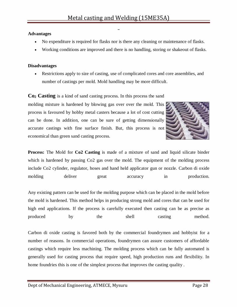
Co2 Casting is a kind of sand casting process. In this process the sand
molding mixture is hardened by blowing gas over over the mold. This
process is favoured by hobby metal casters because a lot of cost cutting
can be done. In addition, one can be sure of getting dimensionally
accurate castings with fine surface finish. But, this process is not
economical than green sand casting process.
Process: The Mold for Co2 Casting is made of a mixture of sand and liquid silicate binder
which is hardened by passing Co2 gas over the mold. The equipment of the molding process
include Co2 cylinder, regulator, hoses and hand held applicator gun or nozzle. Carbon di oxide
molding deliver great accuracy in production.
Any existing pattern can be used for the molding purpose which can be placed in the mold before
the mold is hardened. This method helps in producing strong mold and cores that can be used for
high end applications. If the process is carefully executed then casting can be as precise as
produced by the shell casting method.
Carbon di oxide casting is favored both by the commercial foundrymen and hobbyist for a
number of reasons. In commercial operations, foundrymen can assure customers of affordable
castings which require less machining. The molding process which can be fully automated is
generally used for casting process that require speed, high production runs and flexibility. In
home foundries this is one of the simplest process that improves the casting quality .
Metal casting and Welding (15ME35A)
Dept of Mechanical Engineering, ATMECE, Mysuru Page 29
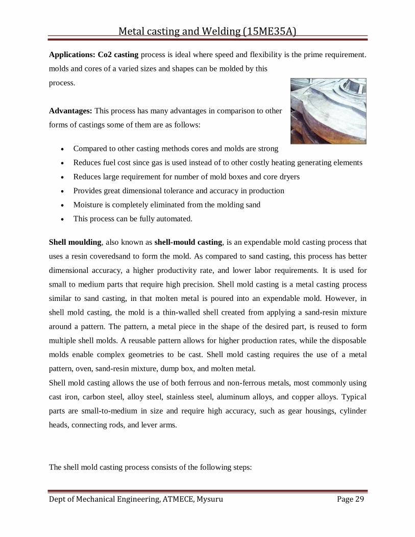
Applications: Co2 casting process is ideal where speed and flexibility is the prime requirement.
molds and cores of a varied sizes and shapes can be molded by this
process.
Advantages: This process has many advantages in comparison to other
forms of castings some of them are as follows:
Compared to other casting methods cores and molds are strong
Reduces fuel cost since gas is used instead of to other costly heating generating elements
Reduces large requirement for number of mold boxes and core dryers
Provides great dimensional tolerance and accuracy in production
Moisture is completely eliminated from the molding sand
This process can be fully automated.
Shell moulding, also known as shell-mould casting, is an expendable mold casting process that
uses a resin coveredsand to form the mold. As compared to sand casting, this process has better
dimensional accuracy, a higher productivity rate, and lower labor requirements. It is used for
small to medium parts that require high precision. Shell mold casting is a metal casting process
similar to sand casting, in that molten metal is poured into an expendable mold. However, in
shell mold casting, the mold is a thin-walled shell created from applying a sand-resin mixture
around a pattern. The pattern, a metal piece in the shape of the desired part, is reused to form
multiple shell molds. A reusable pattern allows for higher production rates, while the disposable
molds enable complex geometries to be cast. Shell mold casting requires the use of a metal
pattern, oven, sand-resin mixture, dump box, and molten metal.
Shell mold casting allows the use of both ferrous and non-ferrous metals, most commonly using
cast iron, carbon steel, alloy steel, stainless steel, aluminum alloys, and copper alloys. Typical
parts are small-to-medium in size and require high accuracy, such as gear housings, cylinder
heads, connecting rods, and lever arms.
The shell mold casting process consists of the following steps:
Metal casting and Welding (15ME35A)
Dept of Mechanical Engineering, ATMECE, Mysuru Page 30
1. Pattern creation - A two-piece metal pattern is created in the shape of the desired
part, typically from iron or steel. Other materials are sometimes used, such as
aluminum for low volume production or graphite for casting reactive materials.
2. Mold creation - First, each pattern half is heated to 175-370 °C (350-700 °F) and
coated with a lubricant to facilitate removal. Next, the heated pattern is clamped
to a dump box, which contains a mixture of sand and a resin binder. The dump
box is inverted, allowing this sand-resin mixture to coat the pattern. The heated
pattern partially cures the mixture, which now forms a shell around the pattern.
Each pattern half and surrounding shell is cured to completion in an oven and then
the shell is ejected from the pattern.
3. Mold assembly - The two shell halves are joined together and securely clamped to
form the complete shell mold. If any cores are required, they are inserted prior to
closing the mold. The shell mold is then placed into a flask and supported by a
backing material.
4. Pouring - The mold is securely clamped together while the molten metal is poured
from a ladle into the gating system and fills the mold cavity.
5. Cooling - After the mold has been filled, the molten metal is allowed to cool and
solidify into the shape of the final casting.
6. Casting removal - After the molten metal has cooled, the mold can be broken and
the casting removed. Trimming and cleaning processes are required to remove
any excess metal from the feed system and any sand from the mold.
1.9. INVESTMENT MOLDING:
Castings can be made from an original wax model (the direct method) or from wax replicas
of an original pattern that need not be made from wax (the indirect method). The following steps
describe the indirect process, which can take two to seven days to complete.
1. Produce a master pattern: An artist or mould-maker creates an original pattern
from wax, clay, wood, plastic, or another material.[4]
2. Create a mould: A mould, known as the master die, is made to fit the master pattern. If
the master pattern was made from steel, the master die can be cast directly from the
pattern using metal with a lower melting point. Rubbermoulds can also be cast directly
Metal casting and Welding (15ME35A)
Dept of Mechanical Engineering, ATMECE, Mysuru Page 31
from the master pattern. Alternatively, a master die can be machined independently—
without creating a master pattern.[4]
3. Produce wax patterns: Although called wax patterns, pattern materials may also include
plastic and frozen mercury.[4]Wax patterns can be produced in one of two ways. In one
process, the wax is poured into the mold and swished around until an even coating,
usually about 3 mm (0.12 in) thick, covers the inner surface of the mould. This is
repeated until the desired pattern thickness is reached. Another method involves filling
the entire mould with molten wax and letting it cool as a solid object.[citation needed]
If a core is required, there are two options: soluble wax or ceramic. Soluble wax cores
are designed to melt out of the investment coating with the rest of the wax pattern;
ceramic cores are removed after the product has hardened.[4]
4. Assemble wax patterns: Multiple wax patterns can be created and assembled into one
large pattern to be cast in one batch pour. In this situation, patterns are attached to a
wax sprue to create a pattern cluster, or tree. To attach patterns, a heating tool is used to
slightly melt designated wax surfaces, which are then pressed against each other and left
to cool and harden. As many as several hundred patterns can be assembled into a
tree.[4][5] Wax patterns can also be chased, which means parting lines or flashings are
rubbed out using the heated metal tool. Finally, patterns are dressed (by removing
imperfections) to look like finished pieces.[6]
5. Apply investment materials: The ceramic mould, known as the investment, is produced by
repeating a series of steps—coating, stuccoing, and hardening—until a desired thickness
is achieved. Coating involves dipping a pattern cluster into a slurry of fine refractory
material and then draining to create a uniform surface coating. Fine materials are used in
this first step, also called a prime coat, to preserve fine details from the
mould. Stuccoing applies coarse ceramic particles by dipping patterns into a fluidised
bed, placing it in a rainfall-sander, or by applying materials by hand. Hardening allows
coatings to cure. These steps are repeated until the investment reaches its required
thickness—usually 5 to 15 mm (0.2 to 0.6 in). Investment moulds are left to dry
completely, which can take 16 to 48 hours. Drying can be accelerated by applying a
vacuum or minimizing environmental humidity. Investment moulds can also be created
by placing the pattern clusters into a flask and then pouring liquid investment material
Metal casting and Welding (15ME35A)
Dept of Mechanical Engineering, ATMECE, Mysuru Page 32
from above. The flask is then vibrated to allow entrapped air to escape and help the
investment material fill any small voids.[4][7] Common refractory materials used to create
the investments are: silica, zircon, various aluminium silicates, and alumina. Silica is
usually used in the fused silica form, but sometimes quartz is used because it is less
expensive. Aluminium silicates are a mixture of alumina and silica, where commonly
used mixtures have an alumina content from 42 to 72%; at 72% alumina the compound is
known as mullite. During the primary coat(s), zircon-based refractories are commonly
used, because zirconium is less likely to react with the molten metal.[7] Prior to silica, a
mixture of plaster and ground up old molds (chamotte) was used.[8] The binders used to
hold the refractory material in place include: ethyl silicate (alcohol-based and chemically
set), colloidal silica (water-based, also known as silica sol, set by drying), sodium
silicate, and a hybrid of these controlled for pH and viscosity.
6. Dewax: Once ceramic moulds have fully cured, they are turned upside-down and placed
in a furnace or autoclave to melt out and/or vaporize the wax. Most shell failures occur at
this point because the waxes used have a thermal expansion coefficient that is much
greater than the investment material surrounding it—as the wax is heated it expands and
introduces stress. To minimize these stresses the wax is heated as rapidly as possible so
that outer wax surfaces can melt and drain quickly, making space for the rest of the wax
to expand. In certain situations, holes may be drilled into the mold before heating to help
reduce these stresses. Any wax that runs out of the mold is usually recovered and reused.
7. Burnout preheating: The mold is then subjected to a burnout, which heats the mold to
between 870 °C and 1095 °C to remove any moisture and residual wax, and to sinter the
mold. Sometimes this heating is also used to preheat the mould before pouring, but other
times the mould is allowed to cool so that it can be tested. Preheating allows the metal to
stay liquid longer so that it can better fill all mould details and increase dimensional
accuracy. If the mold is left to cool, any cracks found can be repaired with ceramic slurry
or special cements.
8. Pouring: The investment mold is then placed open-side up into a tub filled with sand. The
metal may be gravity poured or forced by applying positive air pressure or other
forces. Vacuum casting, tilt casting, pressure assisted pouring and centrifugal casting are
Metal casting and Welding (15ME35A)
Dept of Mechanical Engineering, ATMECE, Mysuru Page 33
methods that use additional forces and are especially useful when moulds contain thin
sections that would be otherwise be difficult to fill
9. Divesting: The shell is hammered, media blasted, vibrated, waterjeted, or chemically
dissolved (sometimes with liquid nitrogen) to release the casting. The sprue is cut off and
recycled. The casting may then be cleaned up to remove signs of the casting process,
usually by grinding.
Course Outcomes:
Students will be able to
1. Use the knowledge of manufacturing processes in selecting suitable and feasible
process to manufacture particular component.
2. Distinguish different verities of casting methods and can select suitable method.
3. Distinguish different types of moulding sands available with their properties.
Questionaire:
1. Explain desirable properties of moulding sand.
2. List and explain types of pattern allowances.
3. List and explain types of patterns
4. Write a note on Binders and additives.
FURTHER READING
1. http://nptel.ac.in/courses/112107084/
2. http://nptel.ac.in/courses/112107144/15
Metal casting and Welding (15ME35A)
Dept of Mechanical Engineering, ATMECE, Mysuru Page 34
MODULE -2
MELTING & METAL MOLD CASTING METHODS
CONTENTS:
2.1. Crucible furnace.
2.2. Cupola
2.3. Operation of cupola
2.4. Pit furnace
2.5. Induction furnace
2.6. Electric arc furnace
2.7. Gravity die casting
2.8. Pressure die casting
2.9. Centrifugal casting
2.10. Squeeze casting process
2.11. Thixocasting
2.12. Continuous casting process
Course Objectives:
1. To understand working principle of different types of furnaces.
2. To get enrich with the knowledge of different metal moulding processes.
Melting is an equally important parameter for obtaining a quality castings. A number of
furnaces can be used for melting the metal, to be used, to make a metal casting. The choice of
furnace depends on the type of metal to be melted. Some of the furnaces used in metal casting
are as following:.
Crucible furnaces
Cupola
Induction furnace
Reverberatory furnace
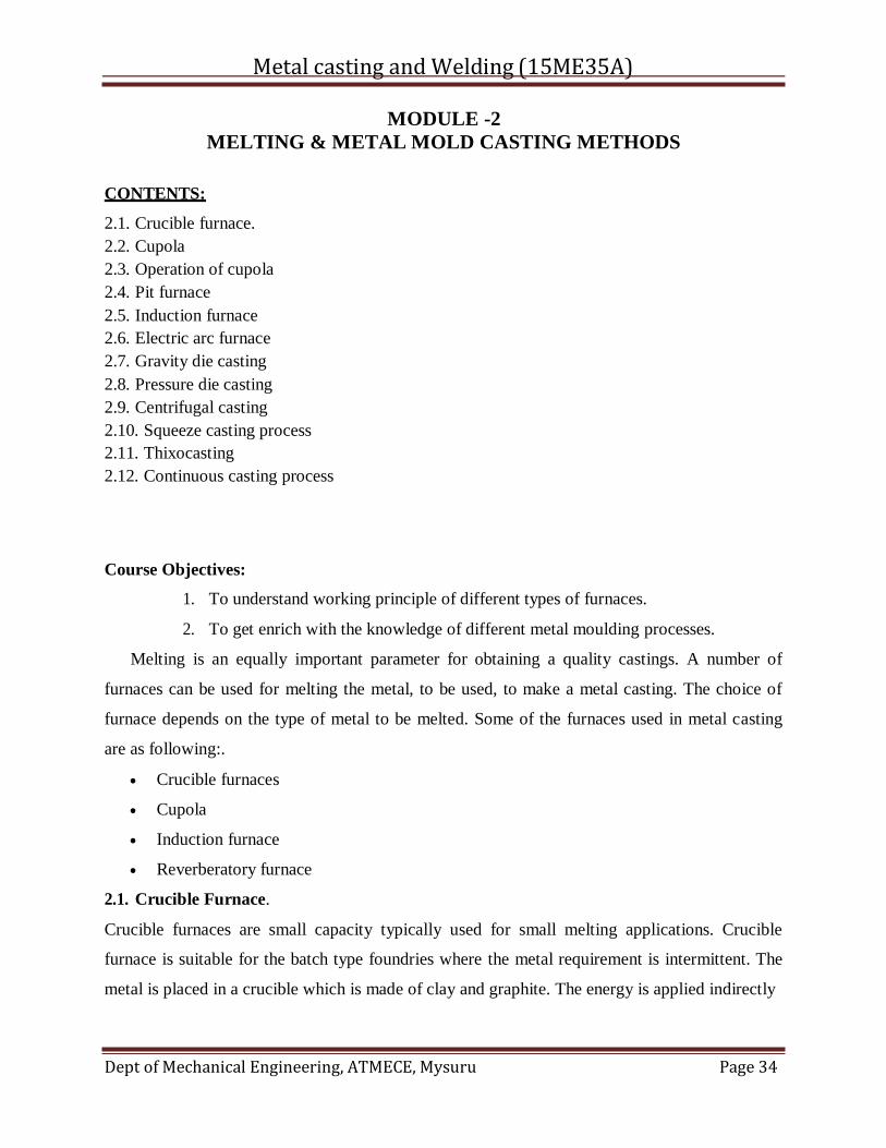
2.1. Crucible Furnace.
Crucible furnaces are small capacity typically used for small melting applications. Crucible
furnace is suitable for the batch type foundries where the metal requirement is intermittent. The
metal is placed in a crucible which is made of clay and graphite. The energy is applied indirectly
Metal casting and Welding (15ME35A)
Dept of Mechanical Engineering, ATMECE, Mysuru Page 35
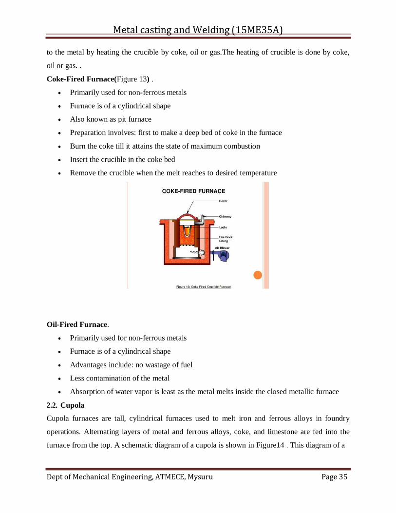
to the metal by heating the crucible by coke, oil or gas.The heating of crucible is done by coke,
oil or gas. .
Coke-Fired Furnace(Figure 13) .
Primarily used for non-ferrous metals
Furnace is of a cylindrical shape
Also known as pit furnace
Preparation involves: first to make a deep bed of coke in the furnace
Burn the coke till it attains the state of maximum combustion
Insert the crucible in the coke bed
Remove the crucible when the melt reaches to desired temperature
Oil-Fired Furnace.
Primarily used for non-ferrous metals
Furnace is of a cylindrical shape
Advantages include: no wastage of fuel
Less contamination of the metal
Absorption of water vapor is least as the metal melts inside the closed metallic furnace
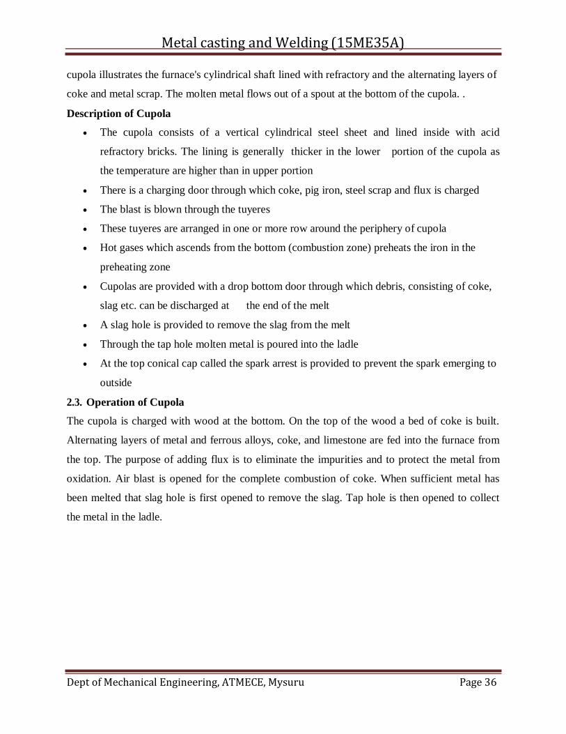
2.2. Cupola
Cupola furnaces are tall, cylindrical furnaces used to melt iron and ferrous alloys in foundry
operations. Alternating layers of metal and ferrous alloys, coke, and limestone are fed into the
furnace from the top. A schematic diagram of a cupola is shown in Figure14 . This diagram of a
Metal casting and Welding (15ME35A)
Dept of Mechanical Engineering, ATMECE, Mysuru Page 36
cupola illustrates the furnace's cylindrical shaft lined with refractory and the alternating layers of
coke and metal scrap. The molten metal flows out of a spout at the bottom of the cupola. .
Description of Cupola
The cupola consists of a vertical cylindrical steel sheet and lined inside with acid
refractory bricks. The lining is generally thicker in the lower portion of the cupola as
the temperature are higher than in upper portion
There is a charging door through which coke, pig iron, steel scrap and flux is charged
The blast is blown through the tuyeres
These tuyeres are arranged in one or more row around the periphery of cupola
Hot gases which ascends from the bottom (combustion zone) preheats the iron in the
preheating zone
Cupolas are provided with a drop bottom door through which debris, consisting of coke,
slag etc. can be discharged at the end of the melt
A slag hole is provided to remove the slag from the melt
Through the tap hole molten metal is poured into the ladle
At the top conical cap called the spark arrest is provided to prevent the spark emerging to
outside
2.3. Operation of Cupola
The cupola is charged with wood at the bottom. On the top of the wood a bed of coke is built.
Alternating layers of metal and ferrous alloys, coke, and limestone are fed into the furnace from
the top. The purpose of adding flux is to eliminate the impurities and to protect the metal from
oxidation. Air blast is opened for the complete combustion of coke. When sufficient metal has
been melted that slag hole is first opened to remove the slag. Tap hole is then opened to collect
the metal in the ladle.
Metal casting and Welding (15ME35A)
Dept of Mechanical Engineering, ATMECE, Mysuru Page 37
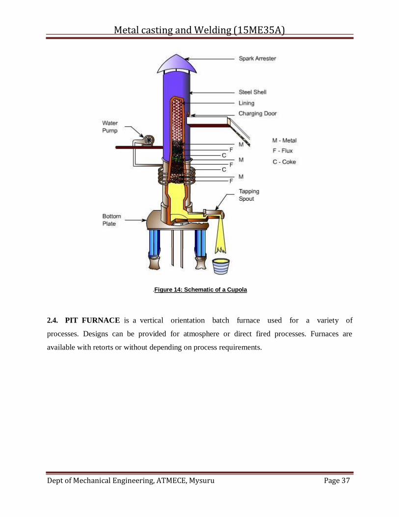
.Figure 14: Schematic of a Cupola
2.4. PIT FURNACE is a vertical orientation batch furnace used for a variety of
processes. Designs can be provided for atmosphere or direct fired processes. Furnaces are
available with retorts or without depending on process requirements.
Metal casting and Welding (15ME35A)
Dept of Mechanical Engineering, ATMECE, Mysuru Page 38
Installed base
Surface Combustion has an installed base of over 200 furnaces worldwide.
Typical processes
Ferritic nitrocarburizing (FNC), nitriding, carburizing, hardening, tempering, stress relieving,
annealing, bluing
Processing atmospheres
Ammonia, disassociated ammonia, endothermic (RX®), exothermic (DX®), nitrogen, air, carbon
dioxide, steam, nitrous oxide, hydrogen or other custom atmosphere mixes
Materials processed
Steel, stainless steel, cast iron, aluminum
Products processed
Gears, bearings, shafts, large components, bars
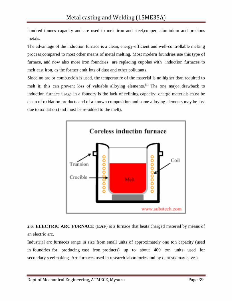
2.5. INDUCTION FURNACE is an electrical furnace in which the heat is applied by induction
heating of metal.[1][2][3] Induction furnace capacities range from less than one kilogram to one
Metal casting and Welding (15ME35A)
Dept of Mechanical Engineering, ATMECE, Mysuru Page 39
hundred tonnes capacity and are used to melt iron and steel,copper, aluminium and precious
metals.
The advantage of the induction furnace is a clean, energy-efficient and well-controllable melting
process compared to most other means of metal melting. Most modern foundries use this type of
furnace, and now also more iron foundries are replacing cupolas with induction furnaces to
melt cast iron, as the former emit lots of dust and other pollutants.
Since no arc or combustion is used, the temperature of the material is no higher than required to
melt it; this can prevent loss of valuable alloying elements.[5] The one major drawback to
induction furnace usage in a foundry is the lack of refining capacity; charge materials must be
clean of oxidation products and of a known composition and some alloying elements may be lost
due to oxidation (and must be re-added to the melt).
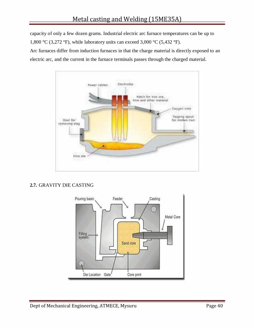
2.6. ELECTRIC ARC FURNACE (EAF) is a furnace that heats charged material by means of
an electric arc.
Industrial arc furnaces range in size from small units of approximately one ton capacity (used
in foundries for producing cast iron products) up to about 400 ton units used for
secondary steelmaking. Arc furnaces used in research laboratories and by dentists may have a
Metal casting and Welding (15ME35A)
Dept of Mechanical Engineering, ATMECE, Mysuru Page 40
capacity of only a few dozen grams. Industrial electric arc furnace temperatures can be up to
1,800 °C (3,272 °F), while laboratory units can exceed 3,000 °C (5,432 °F).
Arc furnaces differ from induction furnaces in that the charge material is directly exposed to an
electric arc, and the current in the furnace terminals passes through the charged material.
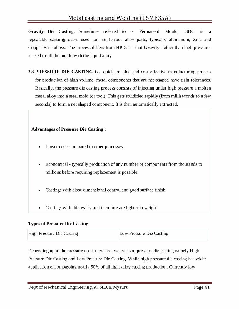
2.7. GRAVITY DIE CASTING
Metal casting and Welding (15ME35A)
Dept of Mechanical Engineering, ATMECE, Mysuru Page 41
Low Pressure Die Casting
Gravity Die Casting. Sometimes referred to as Permanent Mould, GDC is a
repeatable castingprocess used for non-ferrous alloy parts, typically aluminium, Zinc and
Copper Base alloys. The process differs from HPDC in that Gravity- rather than high pressure-
is used to fill the mould with the liquid alloy.
2.8. PRESSURE DIE CASTING is a quick, reliable and cost-effective manufacturing process
for production of high volume, metal components that are net-shaped have tight tolerances.
Basically, the pressure die casting process consists of injecting under high pressure a molten
metal alloy into a steel mold (or tool). This gets solidified rapidly (from milliseconds to a few
seconds) to form a net shaped component. It is then automatically extracted.
Types of Pressure Die Casting
Depending upon the pressure used, there are two types of pressure die casting namely High
Pressure Die Casting and Low Pressure Die Casting. While high pressure die casting has wider
application encompassing nearly 50% of all light alloy casting production. Currently low
Advantages of Pressure Die Casting :
Lower costs compared to other processes.
Economical - typically production of any number of components from thousands to
millions before requiring replacement is possible.
Castings with close dimensional control and good surface finish
Castings with thin walls, and therefore are lighter in weight
High Pressure Die Casting
Metal casting and Welding (15ME35A)
Dept of Mechanical Engineering, ATMECE, Mysuru Page 42
pressure die casting accounts for about 20% of the total production but its use is increasing. High
pressure castings are must for castings requiring tight tolerance and detailed geometry. As the
extra pressure is able to push the metal into more detailed features in the mold. Low pressure die
casting is commonly used for larger and non-critical parts.
However, the machine and its dies are very costly, and for this reason pressure die casting is
viable only for high-volume production.
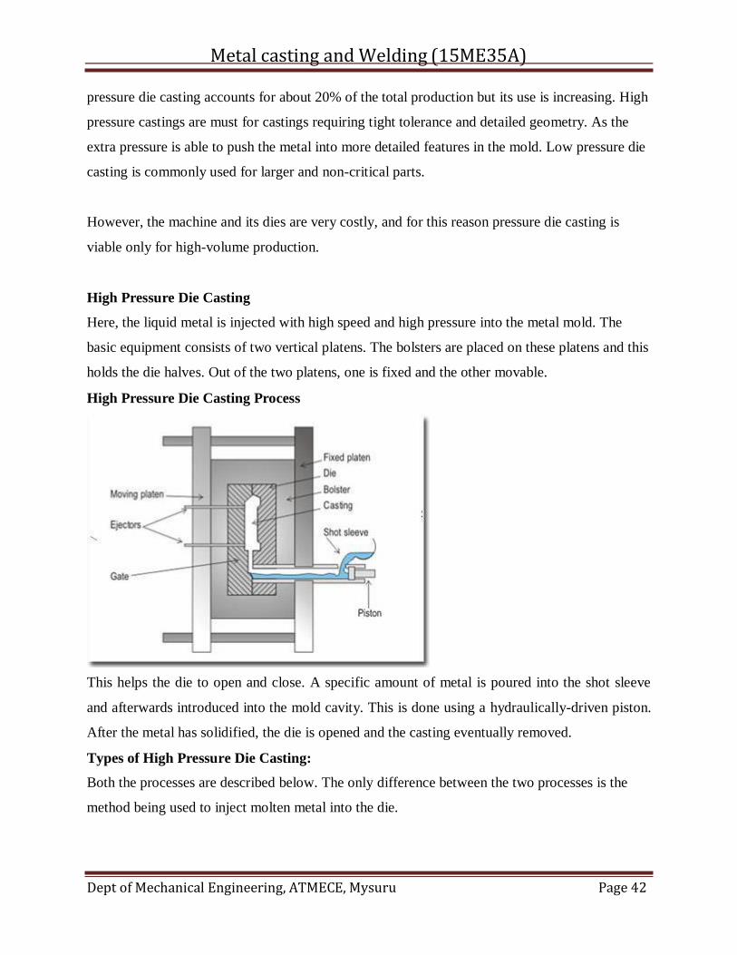
High Pressure Die Casting
Here, the liquid metal is injected with high speed and high pressure into the metal mold. The
basic equipment consists of two vertical platens. The bolsters are placed on these platens and this
holds the die halves. Out of the two platens, one is fixed and the other movable.
High Pressure Die Casting Process
This helps the die to open and close. A specific amount of metal is poured into the shot sleeve
and afterwards introduced into the mold cavity. This is done using a hydraulically-driven piston.
After the metal has solidified, the die is opened and the casting eventually removed.
Types of High Pressure Die Casting:
Both the processes are described below. The only difference between the two processes is the
method being used to inject molten metal into the die.
Metal casting and Welding (15ME35A)
Dept of Mechanical Engineering, ATMECE, Mysuru Page 43
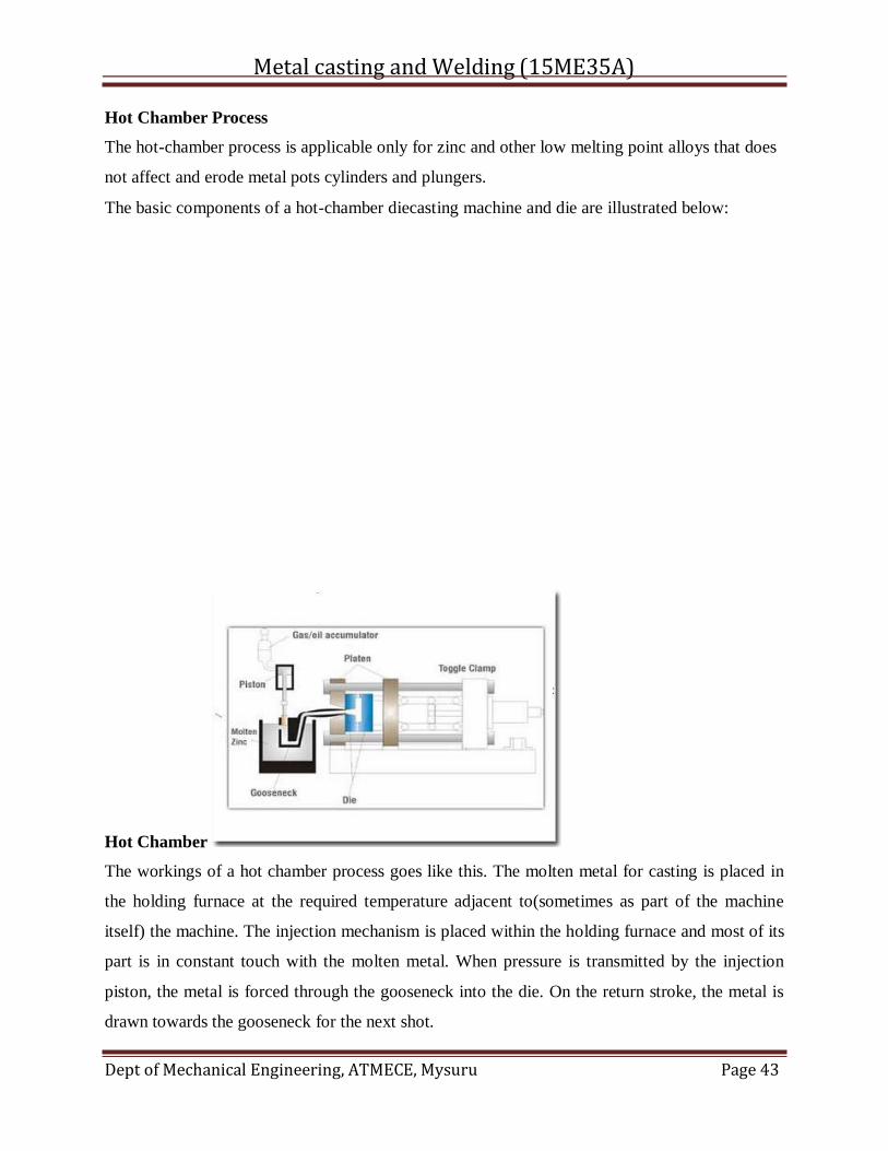
Hot Chamber Process
The hot-chamber process is applicable only for zinc and other low melting point alloys that does
not affect and erode metal pots cylinders and plungers.
The basic components of a hot-chamber diecasting machine and die are illustrated below:
Hot Chamber
The workings of a hot chamber process goes like this. The molten metal for casting is placed in
the holding furnace at the required temperature adjacent to(sometimes as part of the machine
itself) the machine. The injection mechanism is placed within the holding furnace and most of its
part is in constant touch with the molten metal. When pressure is transmitted by the injection
piston, the metal is forced through the gooseneck into the die. On the return stroke, the metal is
drawn towards the gooseneck for the next shot.
Metal casting and Welding (15ME35A)
Dept of Mechanical Engineering, ATMECE, Mysuru Page 44
This process ensures minimum contact between air and the metal to be injected. The tendency
for entrainment of air in the metal during injection is also minimised.
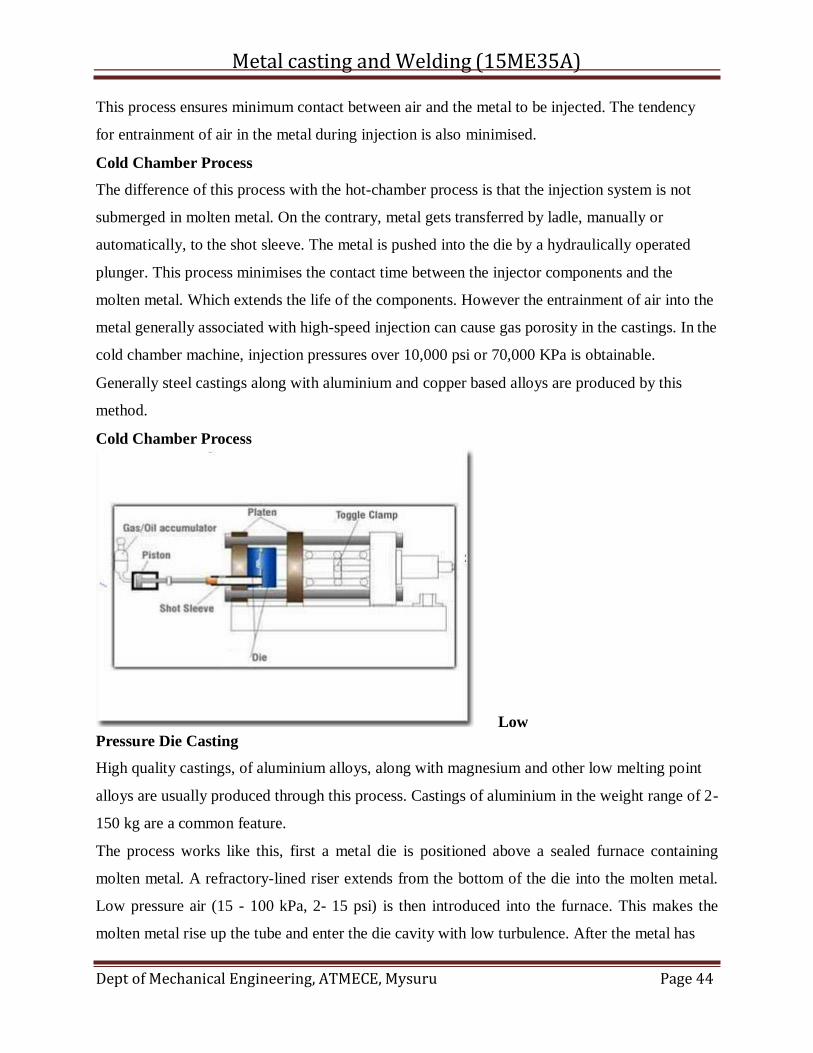
Cold Chamber Process
The difference of this process with the hot-chamber process is that the injection system is not
submerged in molten metal. On the contrary, metal gets transferred by ladle, manually or
automatically, to the shot sleeve. The metal is pushed into the die by a hydraulically operated
plunger. This process minimises the contact time between the injector components and the
molten metal. Which extends the life of the components. However the entrainment of air into the
metal generally associated with high-speed injection can cause gas porosity in the castings. In the
cold chamber machine, injection pressures over 10,000 psi or 70,000 KPa is obtainable.
Generally steel castings along with aluminium and copper based alloys are produced by this
method.
Cold Chamber Process
Low
Pressure Die Casting
High quality castings, of aluminium alloys, along with magnesium and other low melting point
alloys are usually produced through this process. Castings of aluminium in the weight range of 2-
150 kg are a common feature.
The process works like this, first a metal die is positioned above a sealed furnace containing
molten metal. A refractory-lined riser extends from the bottom of the die into the molten metal.
Low pressure air (15 - 100 kPa, 2- 15 psi) is then introduced into the furnace. This makes the
molten metal rise up the tube and enter the die cavity with low turbulence. After the metal has
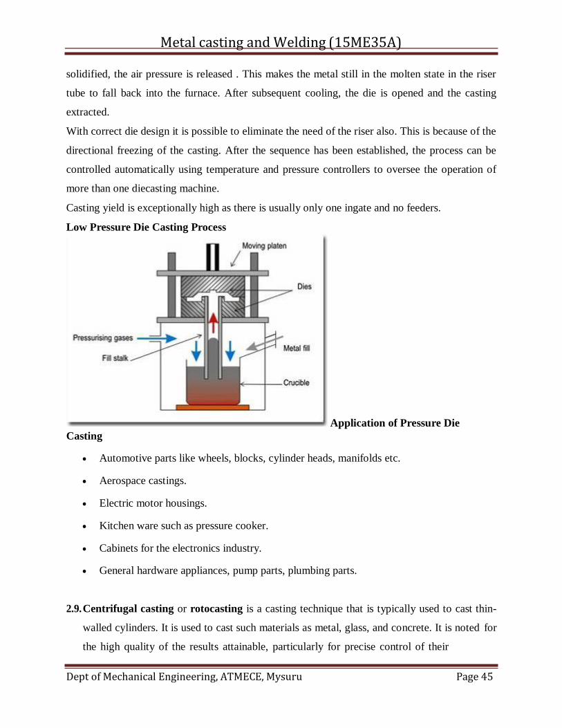
Metal casting and Welding (15ME35A)
Dept of Mechanical Engineering, ATMECE, Mysuru Page 45
solidified, the air pressure is released . This makes the metal still in the molten state in the riser
tube to fall back into the furnace. After subsequent cooling, the die is opened and the casting
extracted.
With correct die design it is possible to eliminate the need of the riser also. This is because of the
directional freezing of the casting. After the sequence has been established, the process can be
controlled automatically using temperature and pressure controllers to oversee the operation of
more than one diecasting machine.
Casting yield is exceptionally high as there is usually only one ingate and no feeders.
Low Pressure Die Casting Process
Application of Pressure Die
Casting
Automotive parts like wheels, blocks, cylinder heads, manifolds etc.
Aerospace castings.
Electric motor housings.
Kitchen ware such as pressure cooker.
Cabinets for the electronics industry.
General hardware appliances, pump parts, plumbing parts.
2.9. Centrifugal casting or rotocasting is a casting technique that is typically used to cast thin-
walled cylinders. It is used to cast such materials as metal, glass, and concrete. It is noted for
the high quality of the results attainable, particularly for precise control of their
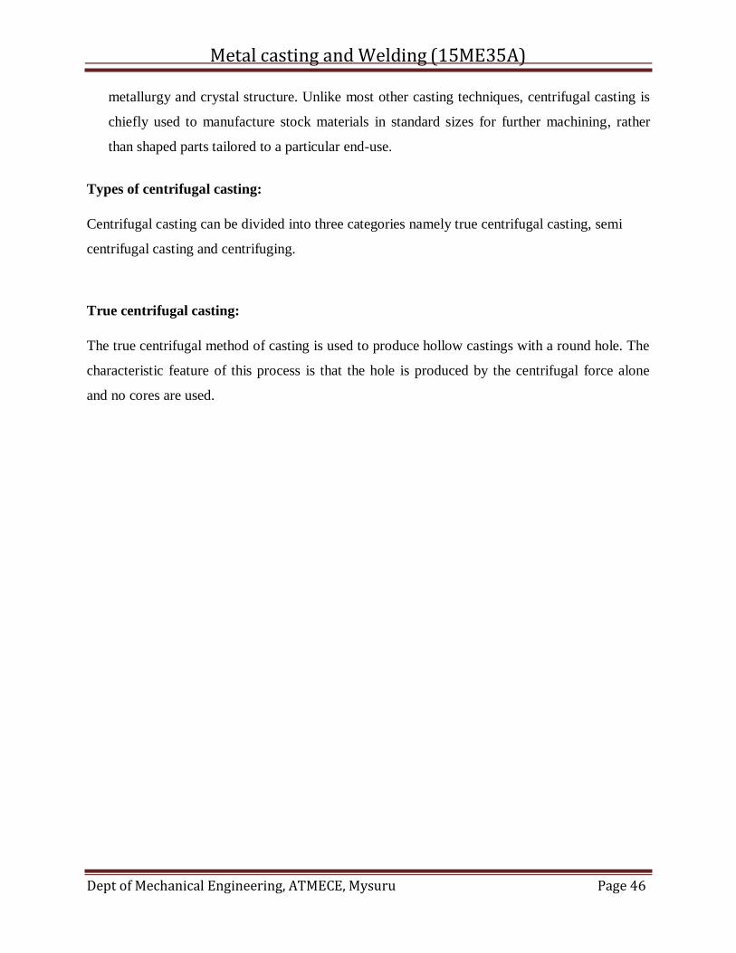
Metal casting and Welding (15ME35A)
Dept of Mechanical Engineering, ATMECE, Mysuru Page 46
metallurgy and crystal structure. Unlike most other casting techniques, centrifugal casting is
chiefly used to manufacture stock materials in standard sizes for further machining, rather
than shaped parts tailored to a particular end-use.
Types of centrifugal casting:
Centrifugal casting can be divided into three categories namely true centrifugal casting, semi
centrifugal casting and centrifuging.
True centrifugal casting:
The true centrifugal method of casting is used to produce hollow castings with a round hole. The
characteristic feature of this process is that the hole is produced by the centrifugal force alone
and no cores are used.
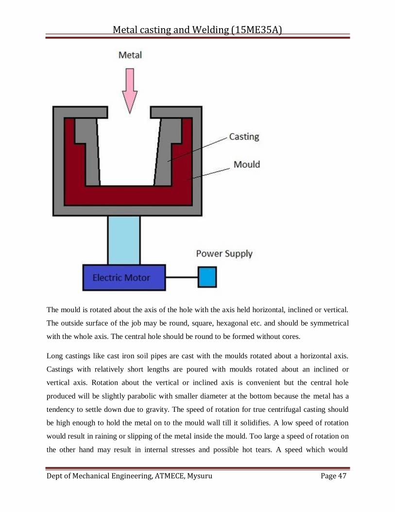
Metal casting and Welding (15ME35A)
Dept of Mechanical Engineering, ATMECE, Mysuru Page 47
The mould is rotated about the axis of the hole with the axis held horizontal, inclined or vertical.
The outside surface of the job may be round, square, hexagonal etc. and should be symmetrical
with the whole axis. The central hole should be round to be formed without cores.
Long castings like cast iron soil pipes are cast with the moulds rotated about a horizontal axis.
Castings with relatively short lengths are poured with moulds rotated about an inclined or
vertical axis. Rotation about the vertical or inclined axis is convenient but the central hole
produced will be slightly parabolic with smaller diameter at the bottom because the metal has a
tendency to settle down due to gravity. The speed of rotation for true centrifugal casting should
be high enough to hold the metal on to the mould wall till it solidifies. A low speed of rotation
would result in raining or slipping of the metal inside the mould. Too large a speed of rotation on
the other hand may result in internal stresses and possible hot tears. A speed which would
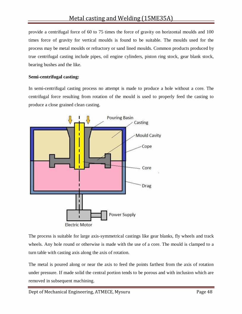
Metal casting and Welding (15ME35A)
Dept of Mechanical Engineering, ATMECE, Mysuru Page 48
provide a centrifugal force of 60 to 75 times the force of gravity on horizontal moulds and 100
times force of gravity for vertical moulds is found to be suitable. The moulds used for the
process may be metal moulds or refractory or sand lined moulds. Common products produced by
true centrifugal casting include pipes, oil engine cylinders, piston ring stock, gear blank stock,
bearing bushes and the like.
Semi-centrifugal casting:
In semi-centrifugal casting process no attempt is made to produce a hole without a core. The
centrifugal force resulting from rotation of the mould is used to properly feed the casting to
produce a close grained clean casting.
The process is suitable for large axis-symmetrical castings like gear blanks, fly wheels and track
wheels. Any hole round or otherwise is made with the use of a core. The mould is clamped to a
turn table with casting axis along the axis of rotation.
The metal is poured along or near the axis to feed the points farthest from the axis of rotation
under pressure. If made solid the central portion tends to be porous and with inclusion which are
removed in subsequent machining.
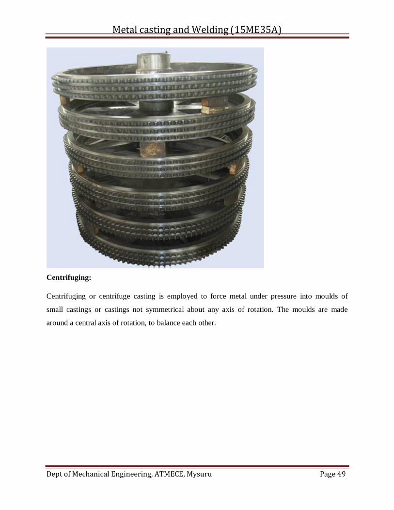
Metal casting and Welding (15ME35A)
Dept of Mechanical Engineering, ATMECE, Mysuru Page 49
Centrifuging:
Centrifuging or centrifuge casting is employed to force metal under pressure into moulds of
small castings or castings not symmetrical about any axis of rotation. The moulds are made
around a central axis of rotation, to balance each other.
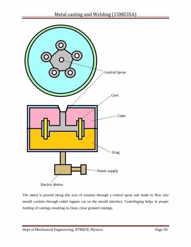
Metal casting and Welding (15ME35A)
Dept of Mechanical Engineering, ATMECE, Mysuru Page 50
The metal is poured along this axis of rotation through a central sprue and made to flow into
mould cavities through radial ingates cut on the mould interface. Centrifuging helps in proper
feeding of castings resulting in clean, close grained castings.
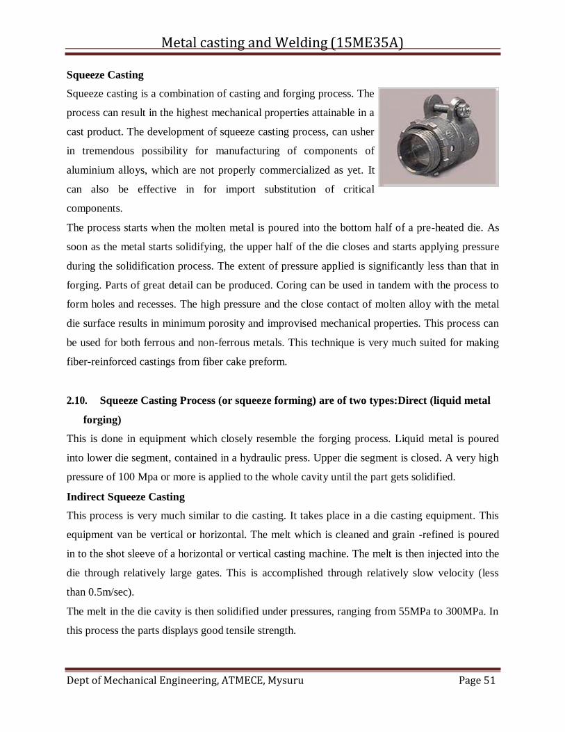
Metal casting and Welding (15ME35A)
Dept of Mechanical Engineering, ATMECE, Mysuru Page 51
Squeeze Casting
Squeeze casting is a combination of casting and forging process. The
process can result in the highest mechanical properties attainable in a
cast product. The development of squeeze casting process, can usher
in tremendous possibility for manufacturing of components of
aluminium alloys, which are not properly commercialized as yet. It
can also be effective in for import substitution of critical
components.
The process starts when the molten metal is poured into the bottom half of a pre-heated die. As
soon as the metal starts solidifying, the upper half of the die closes and starts applying pressure
during the solidification process. The extent of pressure applied is significantly less than that in
forging. Parts of great detail can be produced. Coring can be used in tandem with the process to
form holes and recesses. The high pressure and the close contact of molten alloy with the metal
die surface results in minimum porosity and improvised mechanical properties. This process can
be used for both ferrous and non-ferrous metals. This technique is very much suited for making
fiber-reinforced castings from fiber cake preform.
2.10. Squeeze Casting Process (or squeeze forming) are of two types:Direct (liquid metal
forging)
This is done in equipment which closely resemble the forging process. Liquid metal is poured
into lower die segment, contained in a hydraulic press. Upper die segment is closed. A very high
pressure of 100 Mpa or more is applied to the whole cavity until the part gets solidified.
Indirect Squeeze Casting
This process is very much similar to die casting. It takes place in a die casting equipment. This
equipment van be vertical or horizontal. The melt which is cleaned and grain -refined is poured
in to the shot sleeve of a horizontal or vertical casting machine. The melt is then injected into the
die through relatively large gates. This is accomplished through relatively slow velocity (less
than 0.5m/sec).
The melt in the die cavity is then solidified under pressures, ranging from 55MPa to 300MPa. In
this process the parts displays good tensile strength.
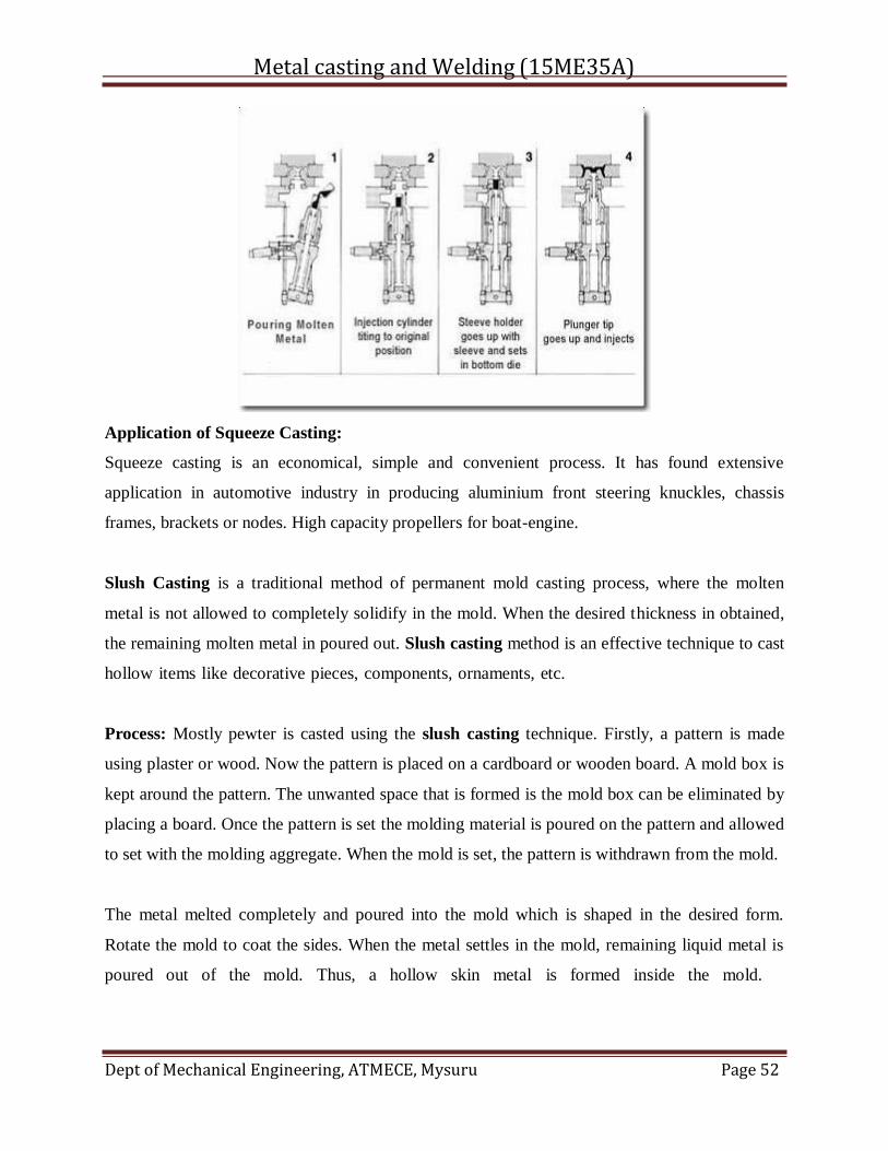
Metal casting and Welding (15ME35A)
Dept of Mechanical Engineering, ATMECE, Mysuru Page 52
Application of Squeeze Casting:
Squeeze casting is an economical, simple and convenient process. It has found extensive
application in automotive industry in producing aluminium front steering knuckles, chassis
frames, brackets or nodes. High capacity propellers for boat-engine.
Slush Casting is a traditional method of permanent mold casting process, where the molten
metal is not allowed to completely solidify in the mold. When the desired thickness in obtained,
the remaining molten metal in poured out. Slush casting method is an effective technique to cast
hollow items like decorative pieces, components, ornaments, etc.
Process: Mostly pewter is casted using the slush casting technique. Firstly, a pattern is made
using plaster or wood. Now the pattern is placed on a cardboard or wooden board. A mold box is
kept around the pattern. The unwanted space that is formed is the mold box can be eliminated by
placing a board. Once the pattern is set the molding material is poured on the pattern and allowed
to set with the molding aggregate. When the mold is set, the pattern is withdrawn from the mold.
The metal melted completely and poured into the mold which is shaped in the desired form.
Rotate the mold to coat the sides. When the metal settles in the mold, remaining liquid metal is
poured out of the mold. Thus, a hollow skin metal is formed inside the mold.
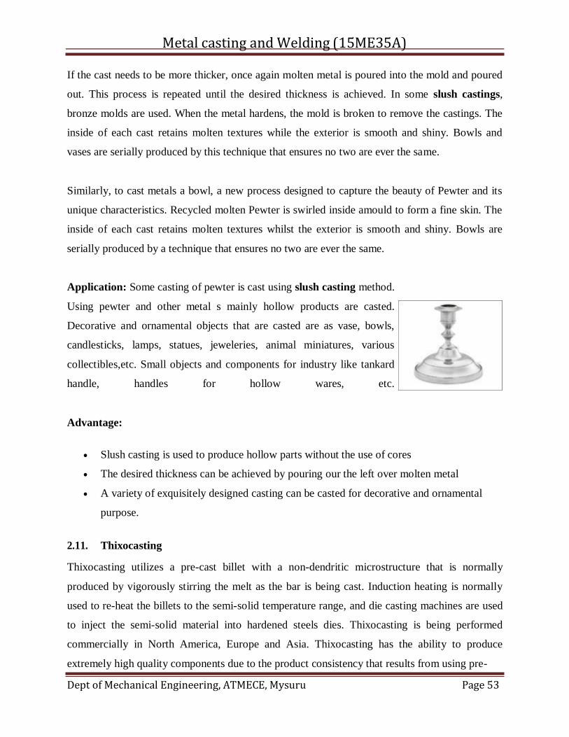
Metal casting and Welding (15ME35A)
Dept of Mechanical Engineering, ATMECE, Mysuru Page 53
If the cast needs to be more thicker, once again molten metal is poured into the mold and poured
out. This process is repeated until the desired thickness is achieved. In some slush castings,
bronze molds are used. When the metal hardens, the mold is broken to remove the castings. The
inside of each cast retains molten textures while the exterior is smooth and shiny. Bowls and
vases are serially produced by this technique that ensures no two are ever the same.
Similarly, to cast metals a bowl, a new process designed to capture the beauty of Pewter and its
unique characteristics. Recycled molten Pewter is swirled inside amould to form a fine skin. The
inside of each cast retains molten textures whilst the exterior is smooth and shiny. Bowls are
serially produced by a technique that ensures no two are ever the same.
Application: Some casting of pewter is cast using slush casting method.
Using pewter and other metal s mainly hollow products are casted.
Decorative and ornamental objects that are casted are as vase, bowls,
candlesticks, lamps, statues, jeweleries, animal miniatures, various
collectibles,etc. Small objects and components for industry like tankard
handle, handles for hollow wares, etc.
Advantage:
Slush casting is used to produce hollow parts without the use of cores
The desired thickness can be achieved by pouring our the left over molten metal
A variety of exquisitely designed casting can be casted for decorative and ornamental
purpose.
2.11. Thixocasting
Thixocasting utilizes a pre-cast billet with a non-dendritic microstructure that is normally
produced by vigorously stirring the melt as the bar is being cast. Induction heating is normally
used to re-heat the billets to the semi-solid temperature range, and die casting machines are used
to inject the semi-solid material into hardened steels dies. Thixocasting is being performed
commercially in North America, Europe and Asia. Thixocasting has the ability to produce
extremely high quality components due to the product consistency that results from using pre-
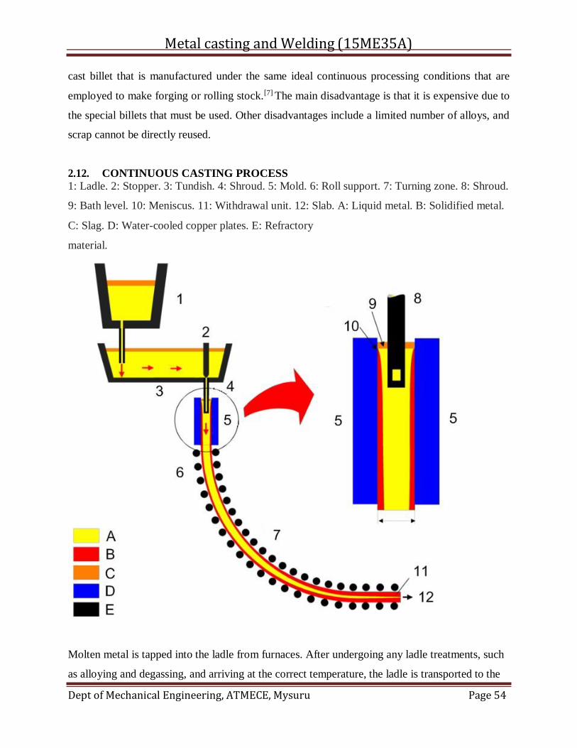
Metal casting and Welding (15ME35A)
Dept of Mechanical Engineering, ATMECE, Mysuru Page 54
cast billet that is manufactured under the same ideal continuous processing conditions that are
employed to make forging or rolling stock.[7] The main disadvantage is that it is expensive due to
the special billets that must be used. Other disadvantages include a limited number of alloys, and
scrap cannot be directly reused.
2.12. CONTINUOUS CASTING PROCESS
1: Ladle. 2: Stopper. 3: Tundish. 4: Shroud. 5: Mold. 6: Roll support. 7: Turning zone. 8: Shroud.
9: Bath level. 10: Meniscus. 11: Withdrawal unit. 12: Slab. A: Liquid metal. B: Solidified metal.
C: Slag. D: Water-cooled copper plates. E: Refractory
material.
Molten metal is tapped into the ladle from furnaces. After undergoing any ladle treatments, such
as alloying and degassing, and arriving at the correct temperature, the ladle is transported to the
Metal casting and Welding (15ME35A)
Dept of Mechanical Engineering, ATMECE, Mysuru Page 55
top of the casting machine. Usually the ladle sits in a slot on a rotating turret at the casting
machine. One ladle is in the 'on-cast' position (feeding the casting machine) while the other is
made ready in the 'off-cast' position, and is switched to the casting position when the first ladle is
empty.
From the ladle, the hot metal is transferred via arefractory shroud (pipe) to a holding bath called
atundish. The tundish allows a reservoir of metal to feed the casting machine while ladles are
switched, thus acting as a buffer of hot metal, as well as smoothing out flow, regulating metal
feed to the molds and cleaning the metal (see below).
Metal is drained from the tundish through another shroud into the top of an open-base
copper mold. The depth of the mold can range from 0.5 to 2 metres (20 to 79 in), depending on
the casting speed and section size. The mold is water-cooled to solidify the hot metal directly in
contact with it; this is the primary cooling process. It also oscillates vertically (or in a near
vertical curved path) to prevent the metal sticking to the mold walls. A lubricant (either powders
that melt on contact with the metal, or liquids) is added to the metal in the mold to prevent
sticking, and to trap any slag particles—including oxide particles or scale—that may be present
in the metal and bring them to the top of the pool to form a floating layer of slag. The shroud is
set so the hot metal exits it below the surface of the slag layer in the mold and is thus called a
submerged entry nozzle (SEN). In some cases, shrouds may not be used between tundish and
mold ('open-pour' casting); in this case, interchangeable metering nozzles in the base of the
tundish direct the metal into the moulds. Some continuous casting layouts feed several molds
from the same tundish.
In the mold, a thin shell of metal next to the mold walls solidifies before the middle section, now
called a strand, exits the base of the mold into a spray chamber. The bulk of metal within the
walls of the strand is still molten. The strand is immediately supported by closely spaced, water-
cooled rollers which support the walls of the strand against the ferrostatic pressure
(compare hydrostatic pressure) of the still-solidifying liquid within the strand. To increase the
rate of solidification, the strand is sprayed with large amounts of water as it passes through the
spray-chamber; this is the secondary coolingprocess. Final solidification of the strand may take
place after the strand has exited the spray-chamber.
It is here that the design of continuous casting machines may vary. This describes a 'curved
apron' casting machine; vertical configurations are also used. In a curved apron casting machine,
Metal casting and Welding (15ME35A)
Dept of Mechanical Engineering, ATMECE, Mysuru Page 56
the strand exits the mold vertically (or on a near vertical curved path) and as it travels through
the spray-chamber, the rollers gradually curve the strand towards the horizontal. In a vertical
casting machine, the strand stays vertical as it passes through the spray-chamber. Molds in a
curved apron casting machine can be straight or curved, depending on the basic design of the
machine.
In a true horizontal casting machine, the mold axis is horizontal and the flow of steel is
horizontal from liquid to thin shell to solid (no bending). In this type of machine, either strand or
mold oscillation is used to prevent sticking in the mold.
After exiting the spray-chamber, the strand passes through straightening rolls (if cast on other
than a vertical machine) and withdrawal rolls. There may be a hot rolling stand after withdrawal
to take advantage of the metal's hot condition to pre-shape the final strand. Finally, the strand is
cut into predetermined lengths by mechanical shears or by travelling oxyacetylene torches, is
marked for identification, and is taken either to a stockpile or to the next forming process.
In many cases the strand may continue through additional rollers and other mechanisms which
may flatten, roll or extrude the metal into its final shape.
Course Outcomes:
Students will be able to
1. Understand the working principles involved with various types of furnaces.
2. Understand and classify different types of metal moulding processes.
Quessionaire:
1. With a neat sketch, explain the working principle of Cupola furnace with different zones.
2. Discuss working principle of induction furnace.
3. Write a note on pressure die casting.
4. Explain thixo casting and slush casting.
Further Reading:
1. http://nptel.ac.in/courses/113104058/
2. http://nptel.ac.in/courses/113104058/16
3. http://nptel.ac.in/courses/112107144/13
Metal casting and Welding (15ME35A)
Dept of Mechanical Engineering, ATMECE, Mysuru Page 57
MODULE -4 WELDING PROCESS
CONTENTS:
4.1. Introduction
4.2. Classification of welding processes
4.3. Manual metal arc welding
4.4. Submerged arc welding
4.5. Tig welding
4.6. Shielded metal arc welding
4.7. Atomic hydrogen welding
4.8. Oxyacetylene/gas welding
4.9. Special types of welding
Course Objectives:
1. To get rich knowledge about welding process and its classification.
2. To understand various types of welding processes and their parameters.
3. To understand special welding processes which are advanced.
4.1. Introduction:
Welding which is the process of joining two metallic components for the desired purpose, can be
defined as the process of joining two similar or dissimilar metallic components with the
application of heat, with or without the application of pressure and with or without the use of
filler metal. Heat may be obtained by chemical reaction, electric arc, electrical resistance,
frictional heat, sound and light energy. If no filter metal is used during welding then it is termed
as ‘Autogenous Welding Process'.
During ‘Bronze Age' parts were joined by forge welding to produce tools, weapons and
ornaments etc, however, present day welding processes have been developed within a period of
about a century.
First application of welding with carbon electrode was developed in 1885 while metal arc
welding with bare electrode was patented in 1890. However, these developments were more of
Metal casting and Welding (15ME35A)
Dept of Mechanical Engineering, ATMECE, Mysuru Page 58
experimental value and applicable only for repair welding but proved to be the important base
for present day manual metal arc (MMAW) welding and other arc welding processes.
In the mean time resistance butt welding was invented in USA in the year 1886. Other resistance
welding processes such as spot and flash welding with manual application of load were
developed around 1905.
With the production of cheap oxygen in 1902, oxy – acetylene welding became feasible in
Europe in 1903.
When the coated electrodes were developed in 1907, the manual metal arc welding process
become viable for production/fabrication of components and assemblies in the industries on large
scale.
Subsequently other developments are as follows:
• Thermit Welding (1903)
• Cellulosic Electrodes (1918)
• Arc Stud Welding (1918)
• Seam Welding of Tubes (1922)
• Mechanical Flash Welder for Joining Rails (1924)
• Extruded Coating for MMAW Electrodes (1926)
• Submerged Arc Welding (1935)
• Air Arc Gouging (1939)
• Inert Gas Tungsten Arc (TIG) Welding (1941)
• Iron Powder Electrodes with High Recovery (1944)
• Inert Gas Metal Arc (MIG) Welding (1948)
• Electro Slag Welding (1951)
• Flux Cored Wire with CO 2 Shielding (1954)
• Electron Beam Welding (1954)
• Constricted Arc (Plasma) for Cutting (1955)
• Friction Welding (1956)
• Plasma Arc Welding (1957)
• Electro Gas Welding (1957)
• Short Circuit Transfer for Low Current, Low Voltage Welding with CO 2 Shielding (1957)
• Vacuum Diffusion Welding (1959)
Metal casting and Welding (15ME35A)
Dept of Mechanical Engineering, ATMECE, Mysuru Page 59
• Explosive Welding (1960)
• Laser Beam Welding (1961)
• High Power CO 2 Laser Beam Welding (1964)
All welded ‘ Liberty ' ships failure in 1942, gave a big jolt to application of welding. However, it
had drawn attention to fracture problem in welded structures.
Applications:
Although most of the welding processes at the time of their developments could not get their
place in the production except for repair welding, however, at the later stage these found proper
place in manufacturing/production. Presently welding is widely being used in fabrication of
pressure vessels, bridges, building structures, aircraft and space crafts, railway coaches and
general applications. It is also being used in shipbuilding, automobile, electrical, electronic and
defense industries, laying of pipe lines and railway tracks and nuclear installations etc.
General Applications:
Welding is vastly being used for construction of transport tankers for transporting oil, water,
milk and fabrication of welded tubes and pipes, chains, LPG cylinders and other items. Steel
furniture, gates, doors and door frames, body and other parts of white goods items such as
refrigerators, washing machines, microwave ovens and many other items of general applications
are fabricated by welding.
Pressure Vessels:
One of the first major use of welding was in the fabrication of pressure vessels. Welding made
considerable increases in the operating temperatures and pressures possible as compared to
riveted pressure vessels.
Bridges:
Early use of welding in bridge construction took place in Australia . This was due to problems in
transporting complete riveted spans or heavy riveting machines necessary for fabrication on site
to remote areas. The first all welded bridge was erected in UK in 1934. Since then all welded
bridges are erected very commonly and successfully.
Ship Building :
Ships were produced earlier by riveting. Over ten million rivets were used in ‘Queen Mary' ship
which required skills and massive organization for riveting but welding would have allowed the
semiskilled/ unskilled labor and the principle of pre-fabrication. Welding found its place in ship
Metal casting and Welding (15ME35A)
Dept of Mechanical Engineering, ATMECE, Mysuru Page 60
building around 1920 and presently all welded ships are widely used. Similarly submarines are
also produced by welding.
Building Structures:
Arc welding is used for construction of steel building leading to considerable savings in steel and
money. In addition to building, huge structures such as steel towers etc also require welding for
fabrication.
Aircraft and Spacecraft:
Similar to ships, aircrafts were produced by riveting in early days but with the introduction of jet
engines welding is widely used for aircraft structure and for joining of skin sheet to body.
Space vehicles which have to encounter frictional heat as well as low temperatures require outer
skin and other parts of special materials. These materials are welded with full success achieving
safety and reliability.
Railways:
Railways use welding extensively for fabrication of coaches and wagons, wheel tyres laying of
new railway tracks by mobile flash butt welding machines and repair of cracked/damaged tracks
by thermit welding.
Automobiles:
Production of automobile components like chassis, body and its structure, fuel tanks and joining
of door hinges require welding.
Electrical Industry:
Starting from generation to distribution and utilization of electrical energy, welding plays
important role. Components of both hydro and steam power generation system, such as
penstocks, water control gates, condensers, electrical transmission towers and distribution system
equipment are fabricated by welding. Turbine blades and cooling fins are also joined by welding.
Electronic Industry:
Electronic industry uses welding to limited extent such as for joining leads of special transistors
but other joining processes such as brazing and soldering are widely being used. Soldering is
used for joining electronic components to printed circuit boards. Robotic soldering is very
Metal casting and Welding (15ME35A)
Dept of Mechanical Engineering, ATMECE, Mysuru Page 61
common for joining of parts to printed circuit boards of computers, television, communication
equipment and other control equipment etc.
Nuclear Installations:
Spheres for nuclear reactor, pipe line bends joining two pipes carrying heavy water and other
components require welding for safe and reliable operations.
Defence Industry:
Defence industry requires welding for joining of many components of war equipment. Tank
bodies fabrication, joining of turret mounting to main body of tanks are typical examples of
applications of welding.
Micro-Joining:
It employs the processes such as micro-plasma, ultrasonic, laser and electron beam welding, for
joining of thin wire to wire, foil to foil and foil to wire, such as producing junctions of
thermocouples, strain gauges to wire leads etc.
Apart from above applications welding is also used for joining of pipes, during laying of crude
oil and gas pipelines, construction of tankers for their storage and transportation. Offshore
structures, dockyards, loading and unloading cranes are also produced by welding.
4.2. Classification of Welding Processes:
Welding processes can be classified based on following criteria;
1. Welding with or without filler material.
2. Source of energy of welding.
3. Arc and Non-arc welding.
4. Fusion and Pressure welding.
1. Welding can be carried out with or without the application of filler material. Earlier only
gas welding was the fusion process in which joining could be achieved with or without
filler material. When welding was done without filler material it was called ‘autogenous
welding'. However, with the development of TIG, electron beam and other welding
processes such classification created confusion as many processes shall be falling in both
the categories.
2. Various sources of energies are used such as chemical, electrical, light, sound,
mechanical energies, but except for chemical energy all other forms of energies are
Metal casting and Welding (15ME35A)
Dept of Mechanical Engineering, ATMECE, Mysuru Page 62
generated from electrical energy for welding. So this criterion does not justify proper
classification.
3. Arc and Non-arc welding processes classification embraces all the arc welding processes
in one class and all other processes in other class. In such classification it is difficult to
assign either of the class to processes such as electroslag welding and flash butt welding,
as in electroslag welding the process starts with arcing and with the melting of sufficient
flux the arc extinguishes while in flash butt welding tiny arcs i.e. sparks are established
during the process and then components are pressed against each other. Therefore, such
classification is also not perfect.
4. Fusion welding and pressure welding is most widely used classification as it covers all
processes in both the categories irrespective of heat source and welding with or without
filler material. In fusion welding all those processes are included where molten metal
solidifies freely while in pressure welding molten metal if any is retained in confined
space under pressure (as may be in case of resistance spot welding or arc stud welding)
solidifies under pressure or semisolid metal cools under pressure. This type of
classification poses no problems so it is considered as the best criterion.
Processes falling under the categories of fusion and pressure welding are shown in Figures 2.1
and 2.2.
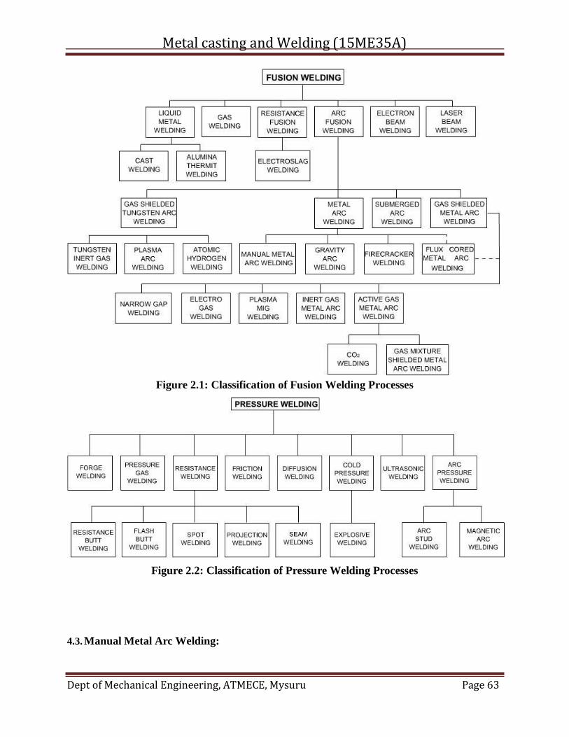
Metal casting and Welding (15ME35A)
Dept of Mechanical Engineering, ATMECE, Mysuru Page 63
Figure 2.1: Classification of Fusion Welding Processes
Figure 2.2: Classification of Pressure Welding Processes
4.3. Manual Metal Arc Welding:

Metal casting and Welding (15ME35A)
Dept of Mechanical Engineering, ATMECE, Mysuru Page 64
Manual metal arc welding (MMAW) or shielded metal arc welding (SMAW) is the oldest and
most widely used process being used for fabrication. The arc is struck between a flux covered
stick electrode and the workpieces. The workpieces are made part of an electric circuit, known as
welding circuit. It includes welding power source, welding cables, electrode holder, earth clamp
and the consumable coated electrode. Figure 5.1 Shows details of welding circuit.
The flux melts along with the metallic core wire and goes to weld pool where it reacts with
molten metal forming slag which floats on the top of molten weld pool and solidifies after
solidification of molten metal and can be removed by chipping and brushing.
Welding power sources used may be transformer or rectifier for AC or DC supply. The
requirement depends on the type of electrode coating and sometimes on the material to be
welded.
The constant-current or drooping type of power source is preferred for manual metal arc welding
since it is difficult to hold a constant arc length. The changing arc length causes arc voltage to
increase or decrease, which in turn produces a change in welding current. The steeper the slope
of the volt-ampere curve within the welding range, the smaller the current change for a given
change in arc voltage. This results into stable arc, uniform penetration and better weld seam
inspite of fluctuations of arc length.
The welding voltages range from 20 to 30 V depending upon welding current i.e. higher the
current, higher the voltage. Welding current depends on the size of the electrode i.e. core
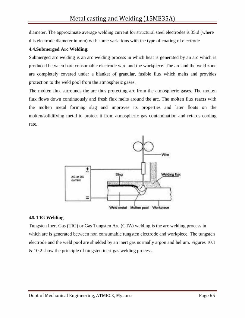
Metal casting and Welding (15ME35A)
Dept of Mechanical Engineering, ATMECE, Mysuru Page 65
diameter. The approximate average welding current for structural steel electrodes is 35.d (where
d is electrode diameter in mm) with some variations with the type of coating of electrode
4.4.Submerged Arc Welding:
Submerged arc welding is an arc welding process in which heat is generated by an arc which is
produced between bare consumable electrode wire and the workpiece. The arc and the weld zone
are completely covered under a blanket of granular, fusible flux which melts and provides
protection to the weld pool from the atmospheric gases.
The molten flux surrounds the arc thus protecting arc from the atmospheric gases. The molten
flux flows down continuously and fresh flux melts around the arc. The molten flux reacts with
the molten metal forming slag and improves its properties and later floats on the
molten/solidifying metal to protect it from atmospheric gas contamination and retards cooling
rate.
4.5. TIG Welding
Tungsten Inert Gas (TIG) or Gas Tungsten Arc (GTA) welding is the arc welding process in
which arc is generated between non consumable tungsten electrode and workpiece. The tungsten
electrode and the weld pool are shielded by an inert gas normally argon and helium. Figures 10.1
& 10.2 show the principle of tungsten inert gas welding process.
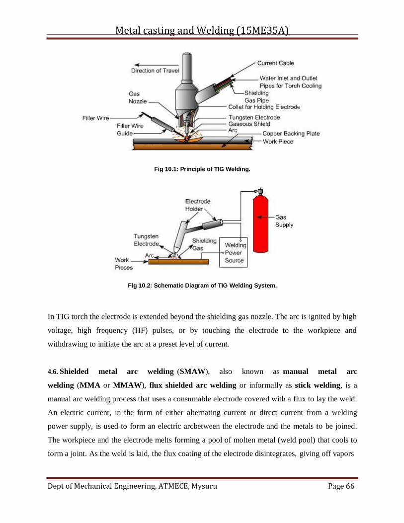
Metal casting and Welding (15ME35A)
Dept of Mechanical Engineering, ATMECE, Mysuru Page 66
Fig 10.1: Principle of TIG Welding.
Fig 10.2: Schematic Diagram of TIG Welding System.
In TIG torch the electrode is extended beyond the shielding gas nozzle. The arc is ignited by high
voltage, high frequency (HF) pulses, or by touching the electrode to the workpiece and
withdrawing to initiate the arc at a preset level of current.
4.6. Shielded metal arc welding (SMAW), also known as manual metal arc
welding (MMA or MMAW), flux shielded arc welding or informally as stick welding, is a
manual arc welding process that uses a consumable electrode covered with a flux to lay the weld.
An electric current, in the form of either alternating current or direct current from a welding
power supply, is used to form an electric arcbetween the electrode and the metals to be joined.
The workpiece and the electrode melts forming a pool of molten metal (weld pool) that cools to
form a joint. As the weld is laid, the flux coating of the electrode disintegrates, giving off vapors
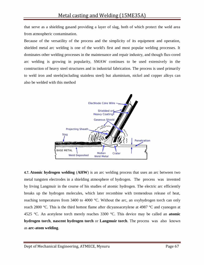
Metal casting and Welding (15ME35A)
Dept of Mechanical Engineering, ATMECE, Mysuru Page 67
that serve as a shielding gasand providing a layer of slag, both of which protect the weld area
from atmospheric contamination.
Because of the versatility of the process and the simplicity of its equipment and operation,
shielded metal arc welding is one of the world's first and most popular welding processes. It
dominates other welding processes in the maintenance and repair industry, and though flux-cored
arc welding is growing in popularity, SMAW continues to be used extensively in the
construction of heavy steel structures and in industrial fabrication. The process is used primarily
to weld iron and steels(including stainless steel) but aluminium, nickel and copper alloys can
also be welded with this method
4.7. Atomic hydrogen welding (AHW) is an arc welding process that uses an arc between two
metal tungsten electrodes in a shielding atmosphere of hydrogen. The process was invented
by Irving Langmuir in the course of his studies of atomic hydrogen. The electric arc efficiently
breaks up the hydrogen molecules, which later recombine with tremendous release of heat,
reaching temperatures from 3400 to 4000 °C. Without the arc, an oxyhydrogen torch can only
reach 2800 °C. This is the third hottest flame after dicyanoacetylene at 4987 °C and cyanogen at
4525 °C. An acetylene torch merely reaches 3300 °C. This device may be called an atomic
hydrogen torch, nascent hydrogen torch or Langmuir torch. The process was also known
as arc-atom welding.
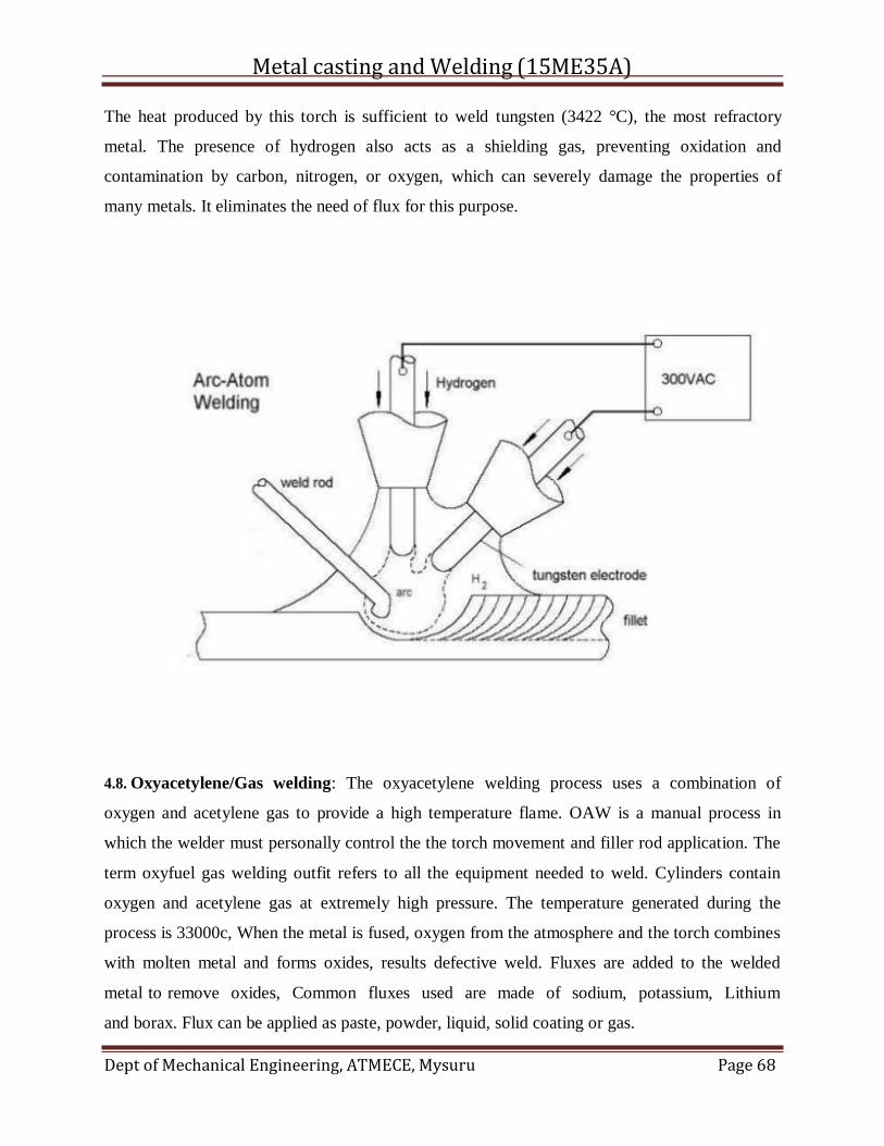
Metal casting and Welding (15ME35A)
Dept of Mechanical Engineering, ATMECE, Mysuru Page 68
The heat produced by this torch is sufficient to weld tungsten (3422 °C), the most refractory
metal. The presence of hydrogen also acts as a shielding gas, preventing oxidation and
contamination by carbon, nitrogen, or oxygen, which can severely damage the properties of
many metals. It eliminates the need of flux for this purpose.
4.8. Oxyacetylene/Gas welding: The oxyacetylene welding process uses a combination of
oxygen and acetylene gas to provide a high temperature flame. OAW is a manual process in
which the welder must personally control the the torch movement and filler rod application. The
term oxyfuel gas welding outfit refers to all the equipment needed to weld. Cylinders contain
oxygen and acetylene gas at extremely high pressure. The temperature generated during the
process is 33000c, When the metal is fused, oxygen from the atmosphere and the torch combines
with molten metal and forms oxides, results defective weld. Fluxes are added to the welded
metal to remove oxides, Common fluxes used are made of sodium, potassium, Lithium
and borax. Flux can be applied as paste, powder, liquid, solid coating or gas.
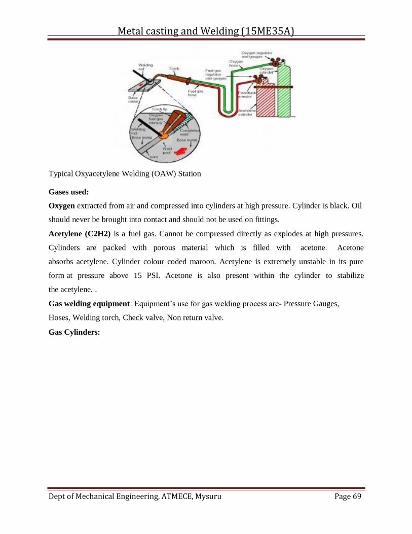
Metal casting and Welding (15ME35A)
Dept of Mechanical Engineering, ATMECE, Mysuru Page 69
Typical Oxyacetylene Welding (OAW) Station
Gases used:
Oxygen extracted from air and compressed into cylinders at high pressure. Cylinder is black. Oil
should never be brought into contact and should not be used on fittings.
Acetylene (C2H2) is a fuel gas. Cannot be compressed directly as explodes at high pressures.
Cylinders are packed with porous material which is filled with acetone. Acetone
absorbs acetylene. Cylinder colour coded maroon. Acetylene is extremely unstable in its pure
form at pressure above 15 PSI. Acetone is also present within the cylinder to stabilize
the acetylene. .
Gas welding equipment: Equipment’s use for gas welding process are- Pressure Gauges,
Hoses, Welding torch, Check valve, Non return valve.
Gas Cylinders:
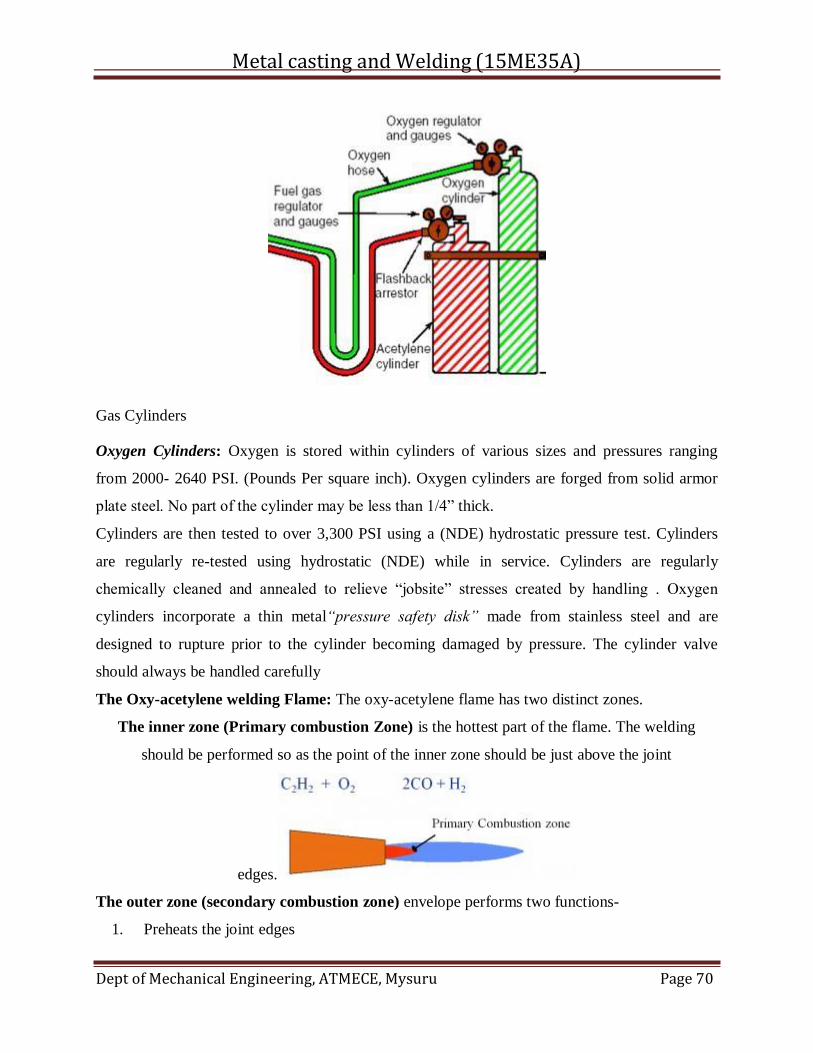
Metal casting and Welding (15ME35A)
Dept of Mechanical Engineering, ATMECE, Mysuru Page 70
Gas Cylinders
Oxygen Cylinders: Oxygen is stored within cylinders of various sizes and pressures ranging
from 2000- 2640 PSI. (Pounds Per square inch). Oxygen cylinders are forged from solid armor
plate steel. No part of the cylinder may be less than 1/4” thick.
Cylinders are then tested to over 3,300 PSI using a (NDE) hydrostatic pressure test. Cylinders
are regularly re-tested using hydrostatic (NDE) while in service. Cylinders are regularly
chemically cleaned and annealed to relieve “jobsite” stresses created by handling . Oxygen
cylinders incorporate a thin metal“pressure safety disk” made from stainless steel and are
designed to rupture prior to the cylinder becoming damaged by pressure. The cylinder valve
should always be handled carefully
The Oxy-acetylene welding Flame: The oxy-acetylene flame has two distinct zones.
The inner zone (Primary combustion Zone) is the hottest part of the flame. The welding
should be performed so as the point of the inner zone should be just above the joint
edges.
The outer zone (secondary combustion zone) envelope performs two functions-
1. Preheats the joint edges
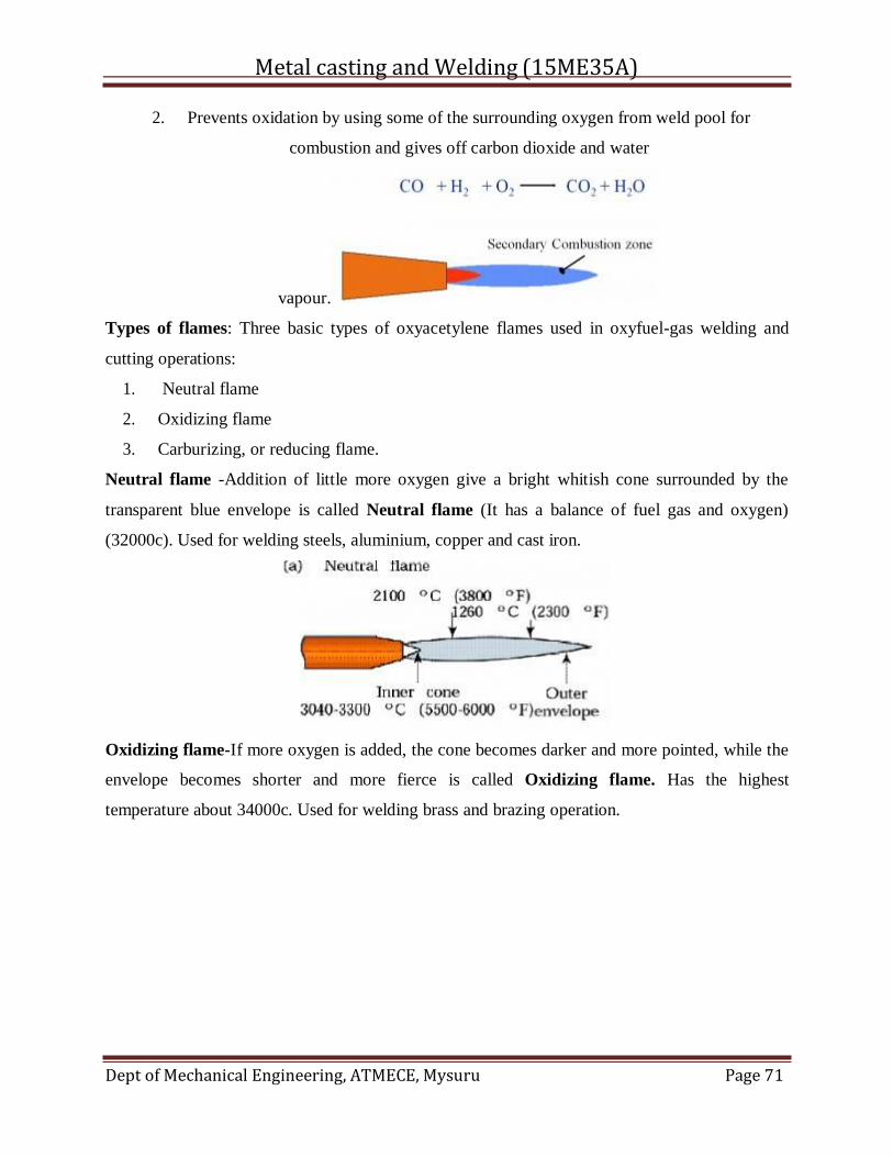
Metal casting and Welding (15ME35A)
Dept of Mechanical Engineering, ATMECE, Mysuru Page 71
2. Prevents oxidation by using some of the surrounding oxygen from weld pool for
combustion and gives off carbon dioxide and water
vapour.
Types of flames: Three basic types of oxyacetylene flames used in oxyfuel-gas welding and
cutting operations:
1. Neutral flame
2. Oxidizing flame
3. Carburizing, or reducing flame.
Neutral flame -Addition of little more oxygen give a bright whitish cone surrounded by the
transparent blue envelope is called Neutral flame (It has a balance of fuel gas and oxygen)
(32000c). Used for welding steels, aluminium, copper and cast iron.
Oxidizing flame-If more oxygen is added, the cone becomes darker and more pointed, while the
envelope becomes shorter and more fierce is called Oxidizing flame. Has the highest
temperature about 34000c. Used for welding brass and brazing operation.
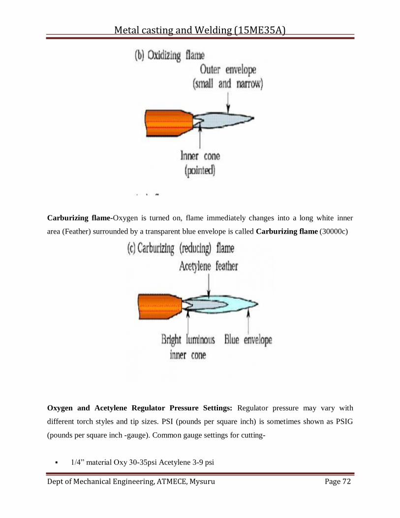
Metal casting and Welding (15ME35A)
Dept of Mechanical Engineering, ATMECE, Mysuru Page 72
Carburizing flame-Oxygen is turned on, flame immediately changes into a long white inner
area (Feather) surrounded by a transparent blue envelope is called Carburizing flame (30000c)
Oxygen and Acetylene Regulator Pressure Settings: Regulator pressure may vary with
different torch styles and tip sizes. PSI (pounds per square inch) is sometimes shown as PSIG
(pounds per square inch -gauge). Common gauge settings for cutting-
1/4” material Oxy 30-35psi Acetylene 3-9 psi
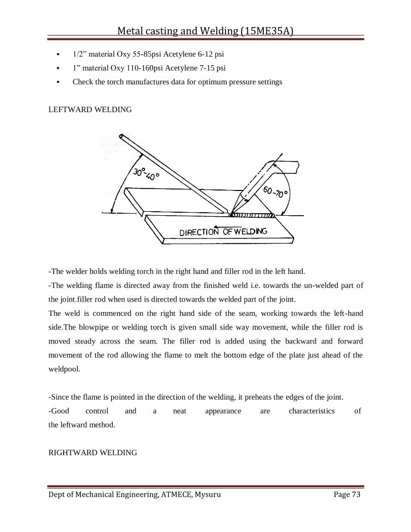
Metal casting and Welding (15ME35A)
Dept of Mechanical Engineering, ATMECE, Mysuru Page 73
1/2” material Oxy 55-85psi Acetylene 6-12 psi
1” material Oxy 110-160psi Acetylene 7-15 psi
Check the torch manufactures data for optimum pressure settings
LEFTWARD WELDING
-The welder holds welding torch in the right hand and filler rod in the left hand.
-The welding flame is directed away from the finished weld i.e. towards the un-welded part of
the joint.filler rod when used is directed towards the welded part of the joint.
The weld is commenced on the right hand side of the seam, working towards the left-hand
side.The blowpipe or welding torch is given small side way movement, while the filler rod is
moved steady across the seam. The filler rod is added using the backward and forward
movement of the rod allowing the flame to melt the bottom edge of the plate just ahead of the
weldpool.
-Since the flame is pointed in the direction of the welding, it preheats the edges of the joint.
-Good control and a neat appearance are characteristics of
the leftward method.
RIGHTWARD WELDING
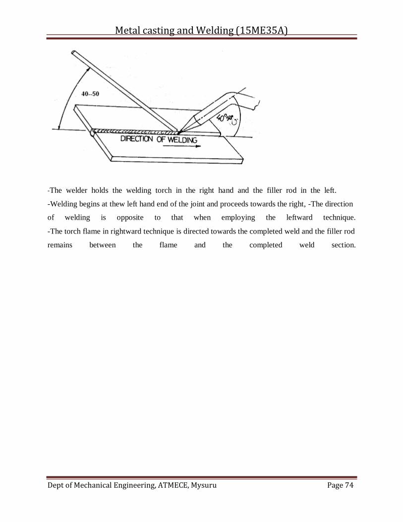
Metal casting and Welding (15ME35A)
Dept of Mechanical Engineering, ATMECE, Mysuru Page 74
-The welder holds the welding torch in the right hand and the filler rod in the left.
-Welding begins at thew left hand end of the joint and proceeds towards the right, -The direction
of welding is opposite to that when employing the leftward technique.
-The torch flame in rightward technique is directed towards the completed weld and the filler rod
remains between the flame and the completed weld section.
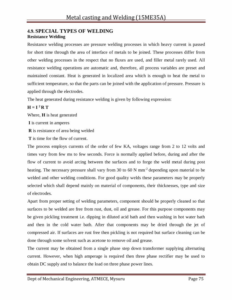
Metal casting and Welding (15ME35A)
Dept of Mechanical Engineering, ATMECE, Mysuru Page 75
4.9. SPECIAL TYPES OF WELDING Resistance Welding
Resistance welding processes are pressure welding processes in which heavy current is passed
for short time through the area of interface of metals to be joined. These processes differ from
other welding processes in the respect that no fluxes are used, and filler metal rarely used. All
resistance welding operations are automatic and, therefore, all process variables are preset and
maintained constant. Heat is generated in localized area which is enough to heat the metal to
sufficient temperature, so that the parts can be joined with the application of pressure. Pressure is
applied through the electrodes.
The heat generated during resistance welding is given by following expression:
H = I 2 R T
Where, H is heat generated
I is current in amperes
R is resistance of area being welded
T is time for the flow of current.
The process employs currents of the order of few KA, voltages range from 2 to 12 volts and
times vary from few ms to few seconds. Force is normally applied before, during and after the
flow of current to avoid arcing between the surfaces and to forge the weld metal during post
heating. The necessary pressure shall vary from 30 to 60 N mm-2 depending upon material to be
welded and other welding conditions. For good quality welds these parameters may be properly
selected which shall depend mainly on material of components, their thicknesses, type and size
of electrodes.
Apart from proper setting of welding parameters, component should be properly cleaned so that
surfaces to be welded are free from rust, dust, oil and grease. For this purpose components may
be given pickling treatment i.e. dipping in diluted acid bath and then washing in hot water bath
and then in the cold water bath. After that components may be dried through the jet of
compressed air. If surfaces are rust free then pickling is not required but surface cleaning can be
done through some solvent such as acetone to remove oil and grease.
The current may be obtained from a single phase step down transformer supplying alternating
current. However, when high amperage is required then three phase rectifier may be used to
obtain DC supply and to balance the load on three phase power lines.
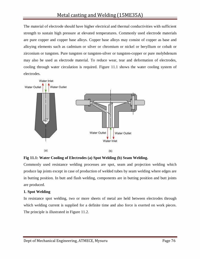
Metal casting and Welding (15ME35A)
Dept of Mechanical Engineering, ATMECE, Mysuru Page 76
The material of electrode should have higher electrical and thermal conductivities with sufficient
strength to sustain high pressure at elevated temperatures. Commonly used electrode materials
are pure copper and copper base alloys. Copper base alloys may consist of copper as base and
alloying elements such as cadmium or silver or chromium or nickel or beryllium or cobalt or
zirconium or tungsten. Pure tungsten or tungsten-silver or tungsten-copper or pure molybdenum
may also be used as electrode material. To reduce wear, tear and deformation of electrodes,
cooling through water circulation is required. Figure 11.1 shows the water cooling system of
electrodes.
Fig 11.1: Water Cooling of Electrodes (a) Spot Welding (b) Seam Welding.
Commonly used resistance welding processes are spot, seam and projection welding which
produce lap joints except in case of production of welded tubes by seam welding where edges are
in butting position. In butt and flash welding, components are in butting position and butt joints
are produced.
1. Spot Welding
In resistance spot welding, two or more sheets of metal are held between electrodes through
which welding current is supplied for a definite time and also force is exerted on work pieces.
The principle is illustrated in Figure 11.2.
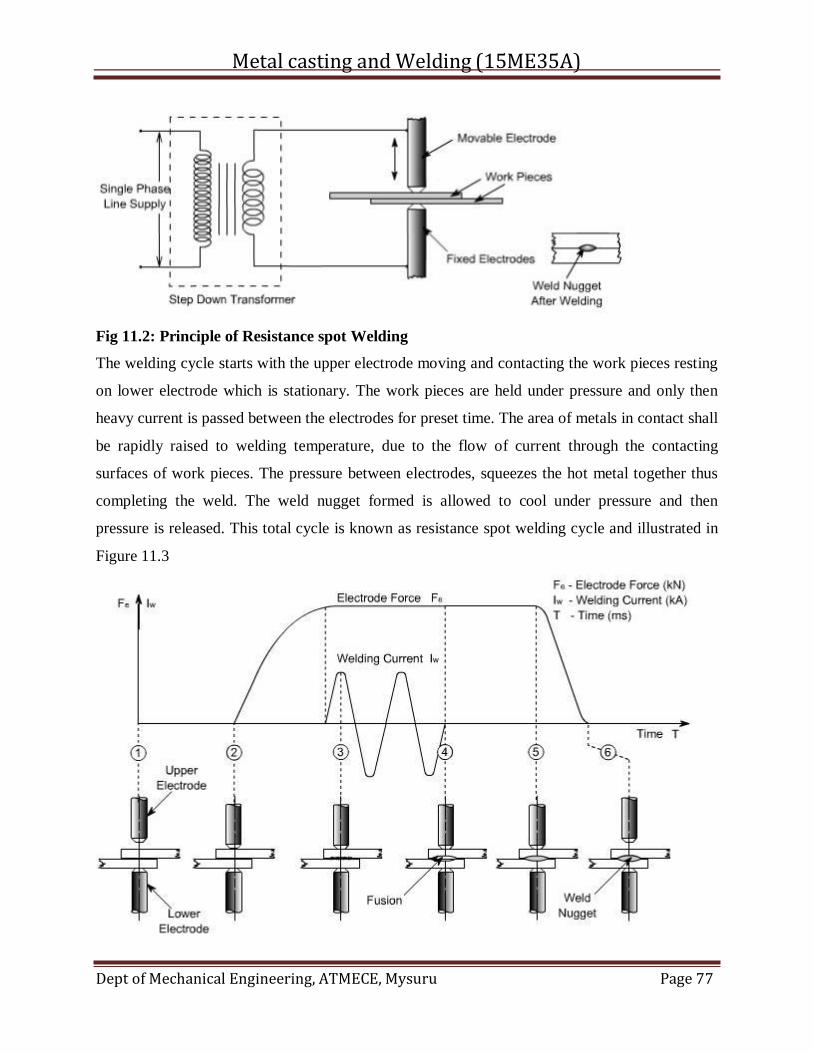
Metal casting and Welding (15ME35A)
Dept of Mechanical Engineering, ATMECE, Mysuru Page 77
Fig 11.2: Principle of Resistance spot Welding
The welding cycle starts with the upper electrode moving and contacting the work pieces resting
on lower electrode which is stationary. The work pieces are held under pressure and only then
heavy current is passed between the electrodes for preset time. The area of metals in contact shall
be rapidly raised to welding temperature, due to the flow of current through the contacting
surfaces of work pieces. The pressure between electrodes, squeezes the hot metal together thus
completing the weld. The weld nugget formed is allowed to cool under pressure and then
pressure is released. This total cycle is known as resistance spot welding cycle and illustrated in
Figure 11.3
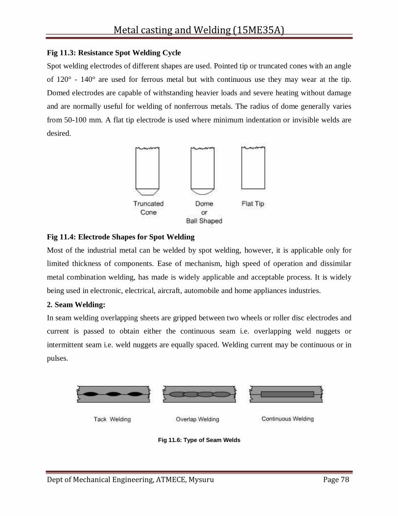
Metal casting and Welding (15ME35A)
Dept of Mechanical Engineering, ATMECE, Mysuru Page 78
Fig 11.3: Resistance Spot Welding Cycle
Spot welding electrodes of different shapes are used. Pointed tip or truncated cones with an angle
of 120° - 140° are used for ferrous metal but with continuous use they may wear at the tip.
Domed electrodes are capable of withstanding heavier loads and severe heating without damage
and are normally useful for welding of nonferrous metals. The radius of dome generally varies
from 50-100 mm. A flat tip electrode is used where minimum indentation or invisible welds are
desired.
Fig 11.4: Electrode Shapes for Spot Welding
Most of the industrial metal can be welded by spot welding, however, it is applicable only for
limited thickness of components. Ease of mechanism, high speed of operation and dissimilar
metal combination welding, has made is widely applicable and acceptable process. It is widely
being used in electronic, electrical, aircraft, automobile and home appliances industries.
2. Seam Welding:
In seam welding overlapping sheets are gripped between two wheels or roller disc electrodes and
current is passed to obtain either the continuous seam i.e. overlapping weld nuggets or
intermittent seam i.e. weld nuggets are equally spaced. Welding current may be continuous or in
pulses.
Fig 11.6: Type of Seam Welds
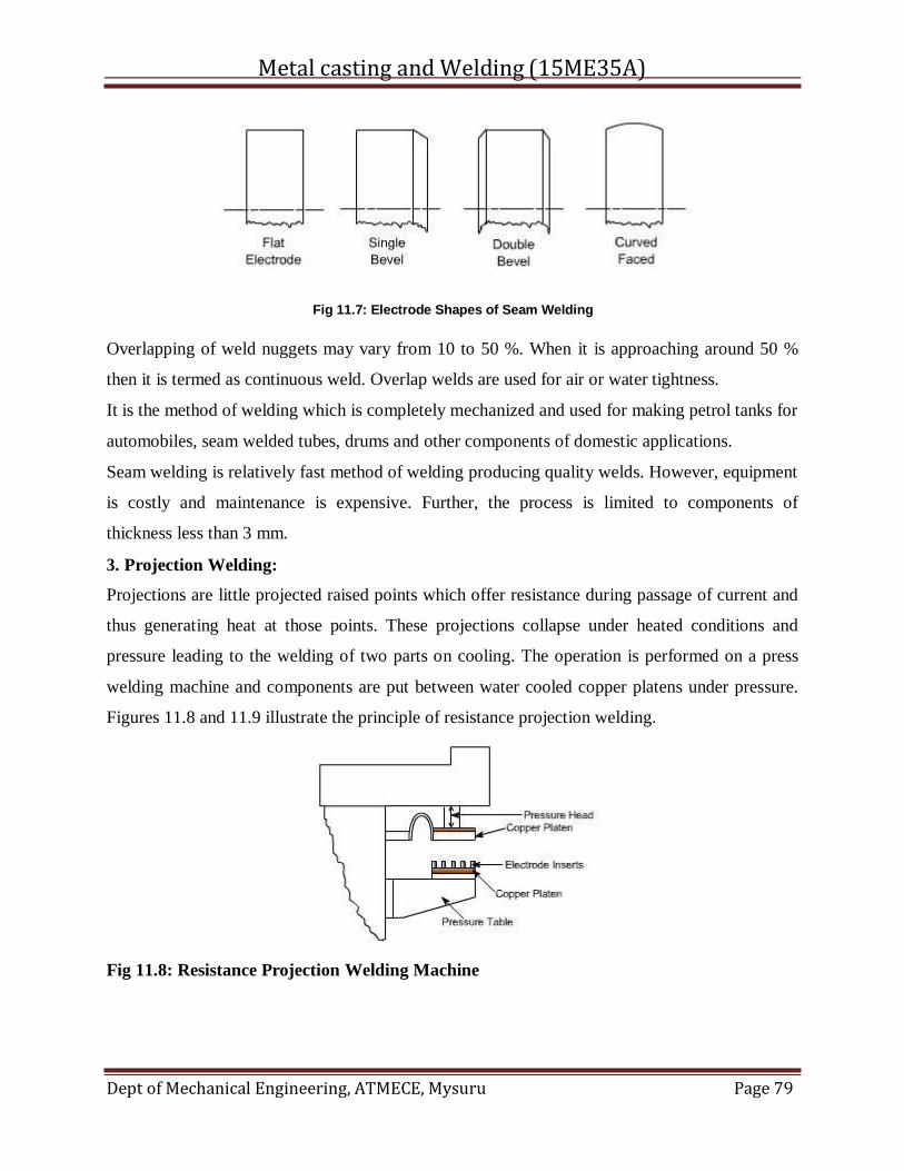
Metal casting and Welding (15ME35A)
Dept of Mechanical Engineering, ATMECE, Mysuru Page 79
Fig 11.7: Electrode Shapes of Seam Welding
Overlapping of weld nuggets may vary from 10 to 50 %. When it is approaching around 50 %
then it is termed as continuous weld. Overlap welds are used for air or water tightness.
It is the method of welding which is completely mechanized and used for making petrol tanks for
automobiles, seam welded tubes, drums and other components of domestic applications.
Seam welding is relatively fast method of welding producing quality welds. However, equipment
is costly and maintenance is expensive. Further, the process is limited to components of
thickness less than 3 mm.
3. Projection Welding:
Projections are little projected raised points which offer resistance during passage of current and
thus generating heat at those points. These projections collapse under heated conditions and
pressure leading to the welding of two parts on cooling. The operation is performed on a press
welding machine and components are put between water cooled copper platens under pressure.
Figures 11.8 and 11.9 illustrate the principle of resistance projection welding.
Fig 11.8: Resistance Projection Welding Machine
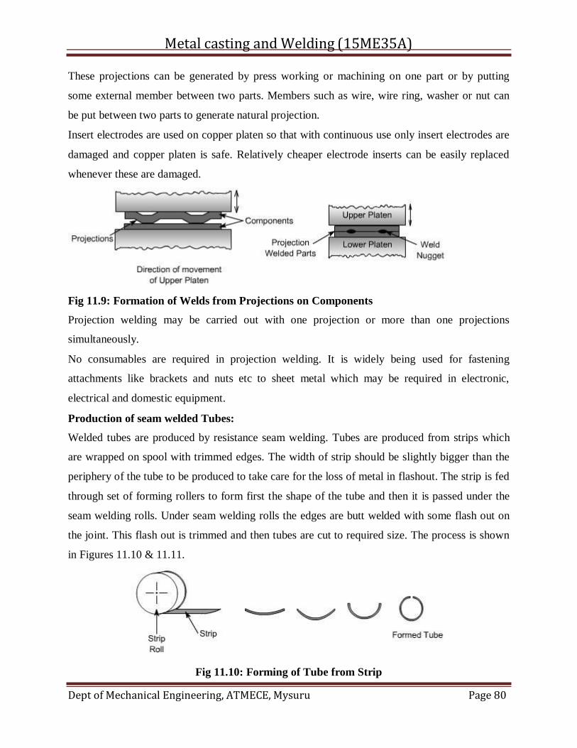
Metal casting and Welding (15ME35A)
Dept of Mechanical Engineering, ATMECE, Mysuru Page 80
These projections can be generated by press working or machining on one part or by putting
some external member between two parts. Members such as wire, wire ring, washer or nut can
be put between two parts to generate natural projection.
Insert electrodes are used on copper platen so that with continuous use only insert electrodes are
damaged and copper platen is safe. Relatively cheaper electrode inserts can be easily replaced
whenever these are damaged.
Fig 11.9: Formation of Welds from Projections on Components
Projection welding may be carried out with one projection or more than one projections
simultaneously.
No consumables are required in projection welding. It is widely being used for fastening
attachments like brackets and nuts etc to sheet metal which may be required in electronic,
electrical and domestic equipment.
Production of seam welded Tubes:
Welded tubes are produced by resistance seam welding. Tubes are produced from strips which
are wrapped on spool with trimmed edges. The width of strip should be slightly bigger than the
periphery of the tube to be produced to take care for the loss of metal in flashout. The strip is fed
through set of forming rollers to form first the shape of the tube and then it is passed under the
seam welding rolls. Under seam welding rolls the edges are butt welded with some flash out on
the joint. This flash out is trimmed and then tubes are cut to required size. The process is shown
in Figures 11.10 & 11.11.
Fig 11.10: Forming of Tube from Strip
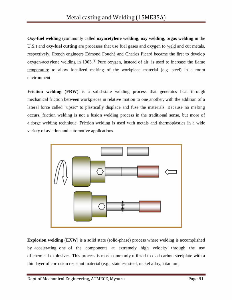
Metal casting and Welding (15ME35A)
Dept of Mechanical Engineering, ATMECE, Mysuru Page 81
Oxy-fuel welding (commonly called oxyacetylene welding, oxy welding, orgas welding in the
U.S.) and oxy-fuel cutting are processes that use fuel gases and oxygen to weld and cut metals,
respectively. French engineers Edmond Fouché and Charles Picard became the first to develop
oxygen-acetylene welding in 1903.[1] Pure oxygen, instead of air, is used to increase the flame
temperature to allow localized melting of the workpiece material (e.g. steel) in a room
environment.
Friction welding (FRW) is a solid-state welding process that generates heat through
mechanical friction between workpieces in relative motion to one another, with the addition of a
lateral force called "upset" to plastically displace and fuse the materials. Because no melting
occurs, friction welding is not a fusion welding process in the traditional sense, but more of
a forge welding technique. Friction welding is used with metals and thermoplastics in a wide
variety of aviation and automotive applications.
Explosion welding (EXW) is a solid state (solid-phase) process where welding is accomplished
by accelerating one of the components at extremely high velocity through the use
of chemical explosives. This process is most commonly utilized to clad carbon steelplate with a
thin layer of corrosion resistant material (e.g., stainless steel, nickel alloy, titanium,
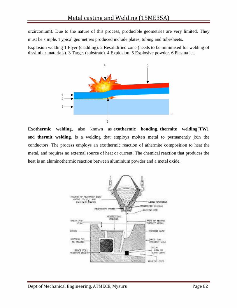
Metal casting and Welding (15ME35A)
Dept of Mechanical Engineering, ATMECE, Mysuru Page 82
orzirconium). Due to the nature of this process, producible geometries are very limited. They
must be simple. Typical geometries produced include plates, tubing and tubesheets.
Explosion welding 1 Flyer (cladding). 2 Resolidified zone (needs to be minimised for welding of
dissimilar materials). 3 Target (substrate). 4 Explosion. 5 Explosive powder. 6 Plasma jet.
Exothermic welding, also known as exothermic bonding, thermite welding(TW),
and thermit welding. is a welding that employs molten metal to permanently join the
conductors. The process employs an exothermic reaction of athermite composition to heat the
metal, and requires no external source of heat or current. The chemical reaction that produces the
heat is an aluminothermic reaction between aluminium powder and a metal oxide.
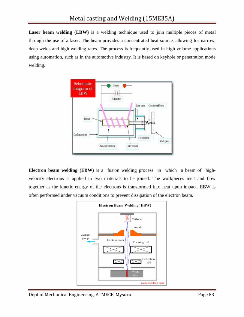
Metal casting and Welding (15ME35A)
Dept of Mechanical Engineering, ATMECE, Mysuru Page 83
Laser beam welding (LBW) is a welding technique used to join multiple pieces of metal
through the use of a laser. The beam provides a concentrated heat source, allowing for narrow,
deep welds and high welding rates. The process is frequently used in high volume applications
using automation, such as in the automotive industry. It is based on keyhole or penetration mode
welding.
Electron beam welding (EBW) is a fusion welding process in which a beam of high-
velocity electrons is applied to two materials to be joined. The workpieces melt and flow
together as the kinetic energy of the electrons is transformed into heat upon impact. EBW is
often performed under vacuum conditions to prevent dissipation of the electron beam.
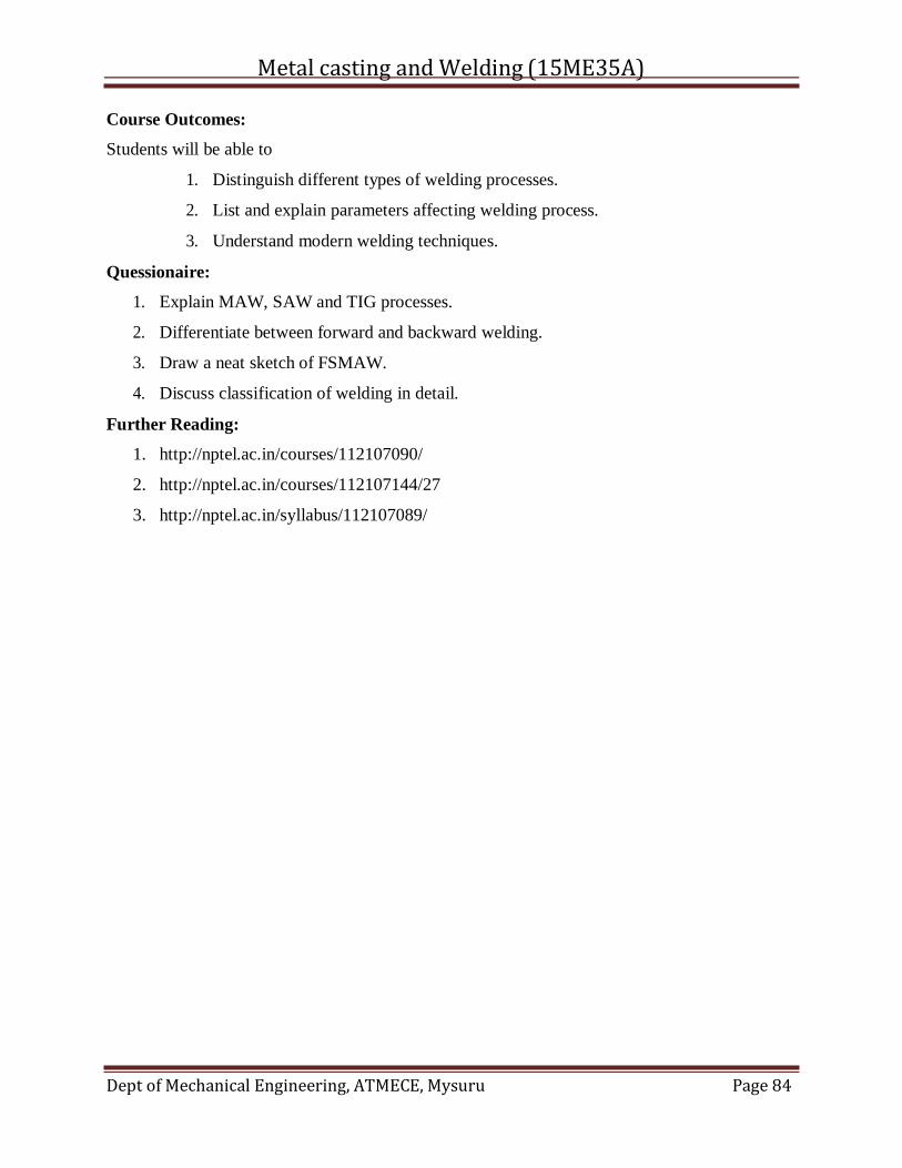
Metal casting and Welding (15ME35A)
Dept of Mechanical Engineering, ATMECE, Mysuru Page 84
Course Outcomes:
Students will be able to
1. Distinguish different types of welding processes.
2. List and explain parameters affecting welding process.
3. Understand modern welding techniques.
Quessionaire:
1. Explain MAW, SAW and TIG processes.
2. Differentiate between forward and backward welding.
3. Draw a neat sketch of FSMAW.
4. Discuss classification of welding in detail.
Further Reading:
1. http://nptel.ac.in/courses/112107090/
2. http://nptel.ac.in/courses/112107144/27
3. http://nptel.ac.in/syllabus/112107089/
Metal casting and Welding (15ME35A)
Dept of Mechanical Engineering, ATMECE, Mysuru Page 85
MODULE -5
SOLDERING , BRAZING AND METALLURGICAL ASPECTS IN
WELDING
CONTENTS:
5.1. Introduction
5.2. Basic Metallurgy of Fusion Welding
5.3.Welding defects
5.4.principles of soldering and brazing
5.5.magnetic particle inspection
5.6.fluorescent penetrant inspection
5.7.industrial radiography
5.8. eddy-current testing
5.9.optical holographic
Course Objectives:
1. To Understand the principle involved in brazing and soldering process.
2. To get enrich about non destructive inspection methods.
3. To classify different welding defects with its features.
5.1. Introduction
In welding, as the heat source interacts with the material, the severity of thermal
excursions experienced by the material varies from region to region, resulting in three distinct
regions in the weldment (Figure 1). These are the fusion zone (FZ), also known as the weld
metal, the heat-affected zone (HAZ), and the unaffected base metal (BM).
5.2. Basic Metallurgy of Fusion Welding
A typical fusion welded joint varies in metallurgical structure from the fusion zone to the base
material with consequential variations in mechanical properties. This is because of the fact that
fusion welding processes result in melting and solidification with very high temperature gradient
within a small zone with the peak temperature at the center of the fusion zone. In general, a weld
can be divided in four different zones as shown schematically in Figure 4.3.1.
Figure 4.3.1 Schematic presentations of several zones in a fusion welded joint
The fusion zone (referred to as FZ) can be characterized as a mixture of completely molten
base metal (and filler metal if consumable electrodes are in use) with high degree of
homogeneity where the mixing is primarily motivated by convection in the molten weld pool.
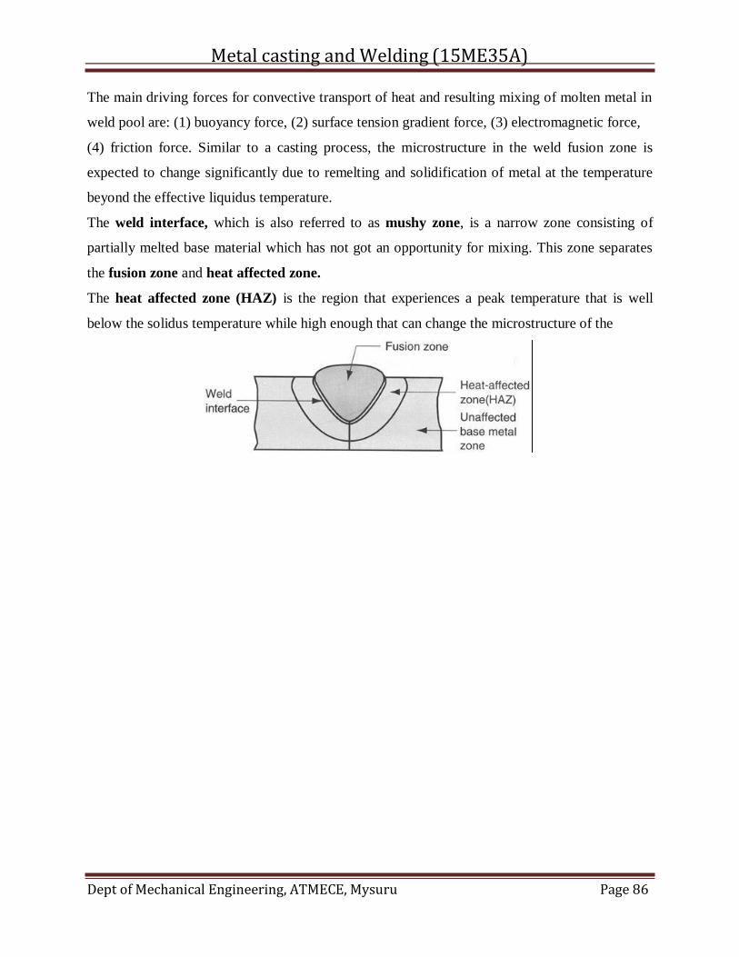
Metal casting and Welding (15ME35A)
Dept of Mechanical Engineering, ATMECE, Mysuru Page 86
The main driving forces for convective transport of heat and resulting mixing of molten metal in
weld pool are: (1) buoyancy force, (2) surface tension gradient force, (3) electromagnetic force,
(4) friction force. Similar to a casting process, the microstructure in the weld fusion zone is
expected to change significantly due to remelting and solidification of metal at the temperature
beyond the effective liquidus temperature.
The weld interface, which is also referred to as mushy zone, is a narrow zone consisting of
partially melted base material which has not got an opportunity for mixing. This zone separates
the fusion zone and heat affected zone.
The heat affected zone (HAZ) is the region that experiences a peak temperature that is well
below the solidus temperature while high enough that can change the microstructure of the
Metal casting and Welding (15ME35A)
Dept of Mechanical Engineering, ATMECE, Mysuru Page 87
material. The amount of change in microstructure in HAZ depends on the amount of heat input,
peak temp reached, time at the elevated temp, and the rate of cooling. As a result of the marked
change in the microstructure, the mechanical properties also change in HAZ and, usually, this
zone remains as the weakest section in a weldment.
The unaffected base metal zone surrounding the HAZ is likely to be in a state of high residual
stress, due to the shrinkage in the fusion zone. However, this zone does not undergo any change
in the microstructure.
The fusion zone and heat affected zone of welded joints can exhibit very different mechanical
properties from that of the unaffected base metal as well as between themselves. For example,
the fusion zone exhibits a typical cast structure while the heat affected zone will exhibit a heat-
treated structure involving phase transformation, recrystallization and grain growth. The
unaffected base metal, on the other hand, will show the original rolled structure with a slight
grain growth.
The heat-affected zone (HAZ) is the area of base material, either a metal or athermoplastic,
which is not melted and has had its microstructure and properties altered by welding or heat
intensive cutting operations. The heat from the welding process and subsequent re-cooling
causes this change from the weld interface to the termination of the sensitizing temperature in the
base metal. The extent and magnitude of property change depends primarily on the base material,
the weld filler metal, and the amount and concentration of heat input by the welding process.
The thermal diffusivity of the base material plays a large role—if the diffusivity is high, the
material cooling rate is high and the HAZ is relatively small. Alternatively, a low diffusivity
leads to slower cooling and a larger HAZ. The amount of heat input during the welding process
also plays an important role as well, as processes likeoxyfuel welding use high heat input and
increase the size of the HAZ. Processes like laser beam welding and electron beam welding give
a highly concentrated, limited amount of heat, resulting in a small HAZ. Arc welding falls
between these two extremes, with the individual processes varying somewhat in heat input.
Mild steel (steel containing a small percentage of carbon, strong and tough but not readily
tempered), also known as plain-carbon steel and Low carbon steel. It is now the most common
form of steel because its price is relatively low while it provides material properties that are
acceptable for many applications. Mild steel contains approximately 0.05–0.25%
Metal casting and Welding (15ME35A)
Dept of Mechanical Engineering, ATMECE, Mysuru Page 88
carbon[1] making it malleable and ductile. Mild steel has a relatively low tensile strength, but it is
cheap and easy to form; surface hardness can be increased through carburizing.[3]
It is often used when large quantities of steel are needed, for example as structural steel. The
density of mild steel is approximately 7.85 g/cm3 (7850 kg/m3 or 0.284 lb/in3)[4] and the Young's
modulus is 200 GPa (29,000,000 psi).[5]
Low-carbon steels suffer from yield-point runout where the material has two yield points. The
first yield point (or upper yield point) is higher than the second and the yield drops dramatically
after the upper yield point. If a low-carbon steel is only stressed to some point between the upper
and lower yield point then the surface develop Lüder bands.[6] Low-carbon steels contain less
carbon than other steels and are easier to cold-form, making them easier to handle.[7]
Carbon steels which can successfully undergo heat-treatment have a carbon content in the range
of 0.30–1.70% by weight. Trace impurities of various other elements can have a significant
effect on the quality of the resulting steel. Trace amounts of sulfur in particular make the
steel red-short, that is, brittle and crumbly at working temperatures. Low-alloy carbon steel, such
as A36 grade, contains about 0.05% sulfur and melts around 1,426–1,538 °C (2,599–
2,800 °F).[8]Manganese is often added to improve the hardenability of low-carbon steels. These
additions turn the material into a low-alloy steel by some definitions, but AISI's definition of
carbon steel allows up to 1.65% manganese by weight.
Welding is a very common manufacturing process that is used to join materials together to form
assemblies and systems. In many cases the welded joints are large, have reduced material
properties (e.g., stress corrosion cracking resistance, fracture toughness), and contain defects.
The welded joints tend to be critical locations in terms of design and sustainment. For this
reason, residual stress in welding is a primary concern. Hill Engineering has extensive
experience with residual stress measurements and welding residual stress.
Residual stress in welding is mainly the result of thermal expansion, which in basic terms means
that materials expand or contract with temperature. Typical engineering materials tend to shrink
in size as they cool. As we all know, welding is a highly thermal process where significant heat
is applied at the weld joint. The material within the weld joint shrinks as it cools and, as a result,
welding residual stress develops as the nearby material pulls back to maintain a bond with the
shrinking weld material.
Metal casting and Welding (15ME35A)
Dept of Mechanical Engineering, ATMECE, Mysuru Page 89
Residual stress in welding is a very common application for Hill Engineering. We work
applications on a daily basis involving measurement of welding residual stress. One of the most
useful techniques for measuring welding residual stress is the contour method. The contour
method provides a 2D map of residual stress, which his helpful for resolving complex details of
the welding residual stress distribution.
We’ll highlight some applications of residual stress in welding in future blog posts and case
studies on our website, so please check back for updates (or subscribe to our mailing list or social
media accounts on the main page). In the meantime, please contact us for more information.
In arc welding an electrode is used to conduct current through a workpiece to fuse two pieces
together. Depending upon the process, the electrode is either consumable, in the case of gas
metal arc welding or shielded metal arc welding, or non-consumable, such as in gas tungsten arc
welding. For a direct current system the weld rod or stick may be a cathode for a filling type
weld or an anode for other welding processes. For an alternating current arc welder the welding
electrode would not be considered an anode or cathode.
A filler metal is a metal added in the making of a joint through welding, brazing, or soldering.
Soldering and brazing processes rely on a filler metal added to the joint to form the junction
between the base metal parts.Soft soldering uses a filler that melts at a lower temperature than
the workpiece, often a lead-tin solder alloy. Brazing andhard soldering use a higher temperature
filler that melts at a temperature which may approach that of the base metal, and which may form
a eutectic alloy with the base metal.
Filler alloys have a lower melting point than the base metal, so that the joint may be made by
bringing the whole assembly up to temperature without everything melting as one. Complex
joints, typically for jewellery or live steam boilermaking may be made in stages, with filler
metals of progressively lower melting points used in turn. Early joints are thus not destroyed by
heating to the later temperatures.
Welding processes work around the melting point of the base metal and require the base metal
itself to begin melting. They usually require more precise distribution of heat from a small torch,
as melting the entire workpiece is avoided by controlling the distribution of heat over space,
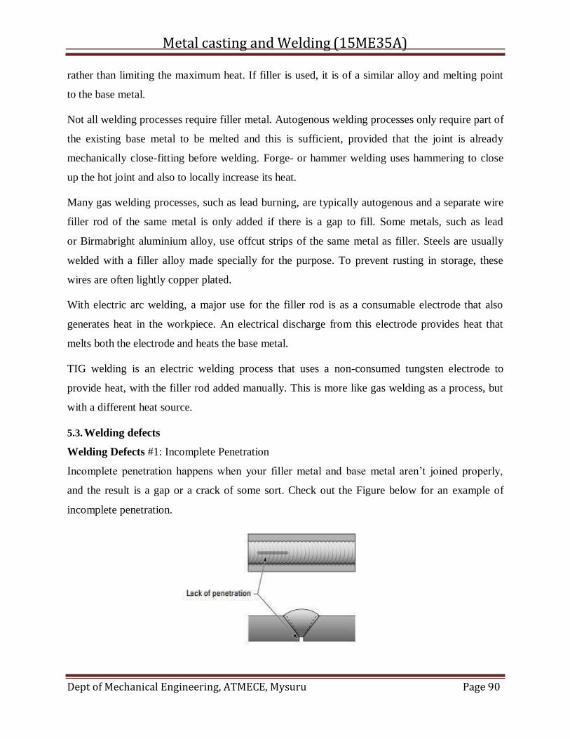
Metal casting and Welding (15ME35A)
Dept of Mechanical Engineering, ATMECE, Mysuru Page 90
rather than limiting the maximum heat. If filler is used, it is of a similar alloy and melting point
to the base metal.
Not all welding processes require filler metal. Autogenous welding processes only require part of
the existing base metal to be melted and this is sufficient, provided that the joint is already
mechanically close-fitting before welding. Forge- or hammer welding uses hammering to close
up the hot joint and also to locally increase its heat.
Many gas welding processes, such as lead burning, are typically autogenous and a separate wire
filler rod of the same metal is only added if there is a gap to fill. Some metals, such as lead
or Birmabright aluminium alloy, use offcut strips of the same metal as filler. Steels are usually
welded with a filler alloy made specially for the purpose. To prevent rusting in storage, these
wires are often lightly copper plated.
With electric arc welding, a major use for the filler rod is as a consumable electrode that also
generates heat in the workpiece. An electrical discharge from this electrode provides heat that
melts both the electrode and heats the base metal.
TIG welding is an electric welding process that uses a non-consumed tungsten electrode to
provide heat, with the filler rod added manually. This is more like gas welding as a process, but
with a different heat source.
5.3. Welding defects
Welding Defects #1: Incomplete Penetration
Incomplete penetration happens when your filler metal and base metal aren’t joined properly,
and the result is a gap or a crack of some sort. Check out the Figure below for an example of
incomplete penetration.
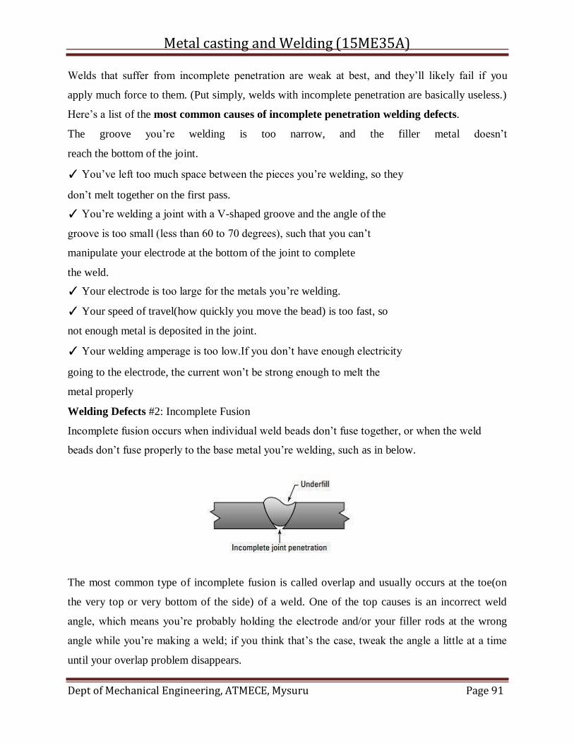
Metal casting and Welding (15ME35A)
Dept of Mechanical Engineering, ATMECE, Mysuru Page 91
Welds that suffer from incomplete penetration are weak at best, and they’ll likely fail if you
apply much force to them. (Put simply, welds with incomplete penetration are basically useless.)
Here’s a list of the most common causes of incomplete penetration welding defects.
The groove you’re welding is too narrow, and the filler metal doesn’t
reach the bottom of the joint.
✓ You’ve left too much space between the pieces you’re welding, so they
don’t melt together on the first pass.
✓ You’re welding a joint with a V-shaped groove and the angle of the
groove is too small (less than 60 to 70 degrees), such that you can’t
manipulate your electrode at the bottom of the joint to complete
the weld.
✓ Your electrode is too large for the metals you’re welding.
✓ Your speed of travel(how quickly you move the bead) is too fast, so
not enough metal is deposited in the joint.
✓ Your welding amperage is too low.If you don’t have enough electricity
going to the electrode, the current won’t be strong enough to melt the
metal properly
Welding Defects #2: Incomplete Fusion
Incomplete fusion occurs when individual weld beads don’t fuse together, or when the weld
beads don’t fuse properly to the base metal you’re welding, such as in below.
The most common type of incomplete fusion is called overlap and usually occurs at the toe(on
the very top or very bottom of the side) of a weld. One of the top causes is an incorrect weld
angle, which means you’re probably holding the electrode and/or your filler rods at the wrong
angle while you’re making a weld; if you think that’s the case, tweak the angle a little at a time
until your overlap problem disappears.
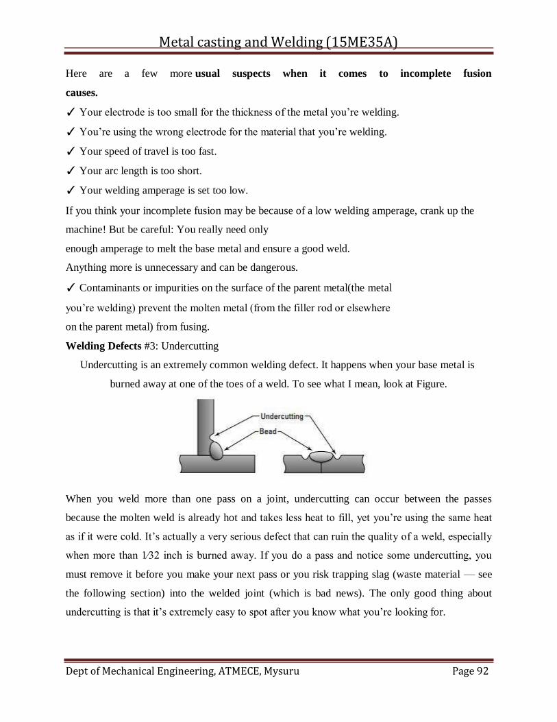
Metal casting and Welding (15ME35A)
Dept of Mechanical Engineering, ATMECE, Mysuru Page 92
Here are a few more usual suspects when it comes to incomplete fusion
causes.
✓ Your electrode is too small for the thickness of the metal you’re welding.
✓ You’re using the wrong electrode for the material that you’re welding.
✓ Your speed of travel is too fast.
✓ Your arc length is too short.
✓ Your welding amperage is set too low.
If you think your incomplete fusion may be because of a low welding amperage, crank up the
machine! But be careful: You really need only
enough amperage to melt the base metal and ensure a good weld.
Anything more is unnecessary and can be dangerous.
✓ Contaminants or impurities on the surface of the parent metal(the metal
you’re welding) prevent the molten metal (from the filler rod or elsewhere
on the parent metal) from fusing.
Welding Defects #3: Undercutting
Undercutting is an extremely common welding defect. It happens when your base metal is
burned away at one of the toes of a weld. To see what I mean, look at Figure.
When you weld more than one pass on a joint, undercutting can occur between the passes
because the molten weld is already hot and takes less heat to fill, yet you’re using the same heat
as if it were cold. It’s actually a very serious defect that can ruin the quality of a weld, especially
when more than 1⁄32 inch is burned away. If you do a pass and notice some undercutting, you
must remove it before you make your next pass or you risk trapping slag (waste material — see
the following section) into the welded joint (which is bad news). The only good thing about
undercutting is that it’s extremely easy to spot after you know what you’re looking for.
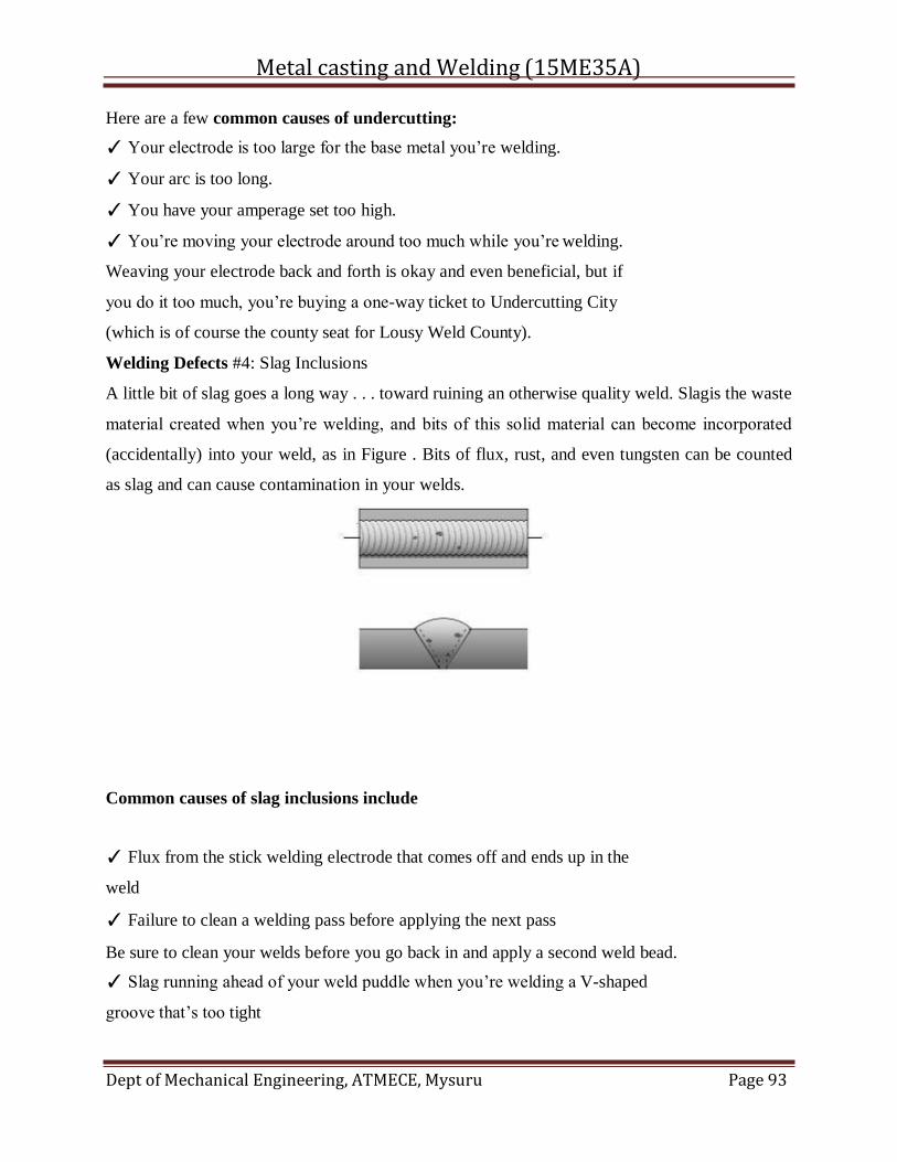
Metal casting and Welding (15ME35A)
Dept of Mechanical Engineering, ATMECE, Mysuru Page 93
Here are a few common causes of undercutting:
✓ Your electrode is too large for the base metal you’re welding.
✓ Your arc is too long.
✓ You have your amperage set too high.
✓ You’re moving your electrode around too much while you’re welding.
Weaving your electrode back and forth is okay and even beneficial, but if
you do it too much, you’re buying a one-way ticket to Undercutting City
(which is of course the county seat for Lousy Weld County).
Welding Defects #4: Slag Inclusions
A little bit of slag goes a long way . . . toward ruining an otherwise quality weld. Slagis the waste
material created when you’re welding, and bits of this solid material can become incorporated
(accidentally) into your weld, as in Figure . Bits of flux, rust, and even tungsten can be counted
as slag and can cause contamination in your welds.
Common causes of slag inclusions include
✓ Flux from the stick welding electrode that comes off and ends up in the
weld
✓ Failure to clean a welding pass before applying the next pass
Be sure to clean your welds before you go back in and apply a second weld bead.
✓ Slag running ahead of your weld puddle when you’re welding a V-shaped
groove that’s too tight
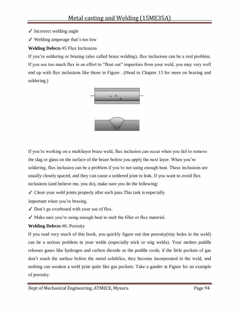
Metal casting and Welding (15ME35A)
Dept of Mechanical Engineering, ATMECE, Mysuru Page 94
✓ Incorrect welding angle
✓ Welding amperage that’s too low
Welding Defects #5 Flux Inclusions
If you’re soldering or brazing (also called braze welding), flux inclusions can be a real problem.
If you use too much flux in an effort to “float out” impurities from your weld, you may very well
end up with flux inclusions like those in Figure . (Head to Chapter 13 for more on brazing and
soldering.)
If you’re working on a multilayer braze weld, flux inclusion can occur when you fail to remove
the slag or glass on the surface of the braze before you apply the next layer. When you’re
soldering, flux inclusion can be a problem if you’re not using enough heat. These inclusions are
usually closely spaced, and they can cause a soldered joint to leak. If you want to avoid flux
inclusions (and believe me, you do), make sure you do the following:
✓ Clean your weld joints properly after each pass.This task is especially
important when you’re brazing.
✓ Don’t go overboard with your use of flux.
✓ Make sure you’re using enough heat to melt the filler or flux material.
Welding Defects #6: Porosity
If you read very much of this book, you quickly figure out that porosity(tiny holes in the weld)
can be a serious problem in your welds (especially stick or mig welds). Your molten puddle
releases gases like hydrogen and carbon dioxide as the puddle cools; if the little pockets of gas
don’t reach the surface before the metal solidifies, they become incorporated in the weld, and
nothing can weaken a weld joint quite like gas pockets. Take a gander at Figure for an example
of porosity.
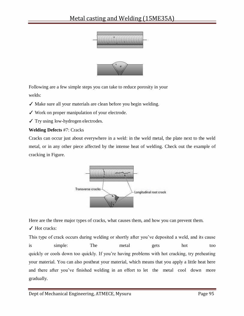
Metal casting and Welding (15ME35A)
Dept of Mechanical Engineering, ATMECE, Mysuru Page 95
Following are a few simple steps you can take to reduce porosity in your
welds:
✓ Make sure all your materials are clean before you begin welding.
✓ Work on proper manipulation of your electrode.
✓ Try using low-hydrogen electrodes.
Welding Defects #7: Cracks
Cracks can occur just about everywhere in a weld: in the weld metal, the plate next to the weld
metal, or in any other piece affected by the intense heat of welding. Check out the example of
cracking in Figure.
Here are the three major types of cracks, what causes them, and how you can prevent them.
✓ Hot cracks:
This type of crack occurs during welding or shortly after you’ve deposited a weld, and its cause
is simple: The metal gets hot too
quickly or cools down too quickly. If you’re having problems with hot cracking, try preheating
your material. You can also postheat your material, which means that you apply a little heat here
and there after you’ve finished welding in an effort to let the metal cool down more
gradually.
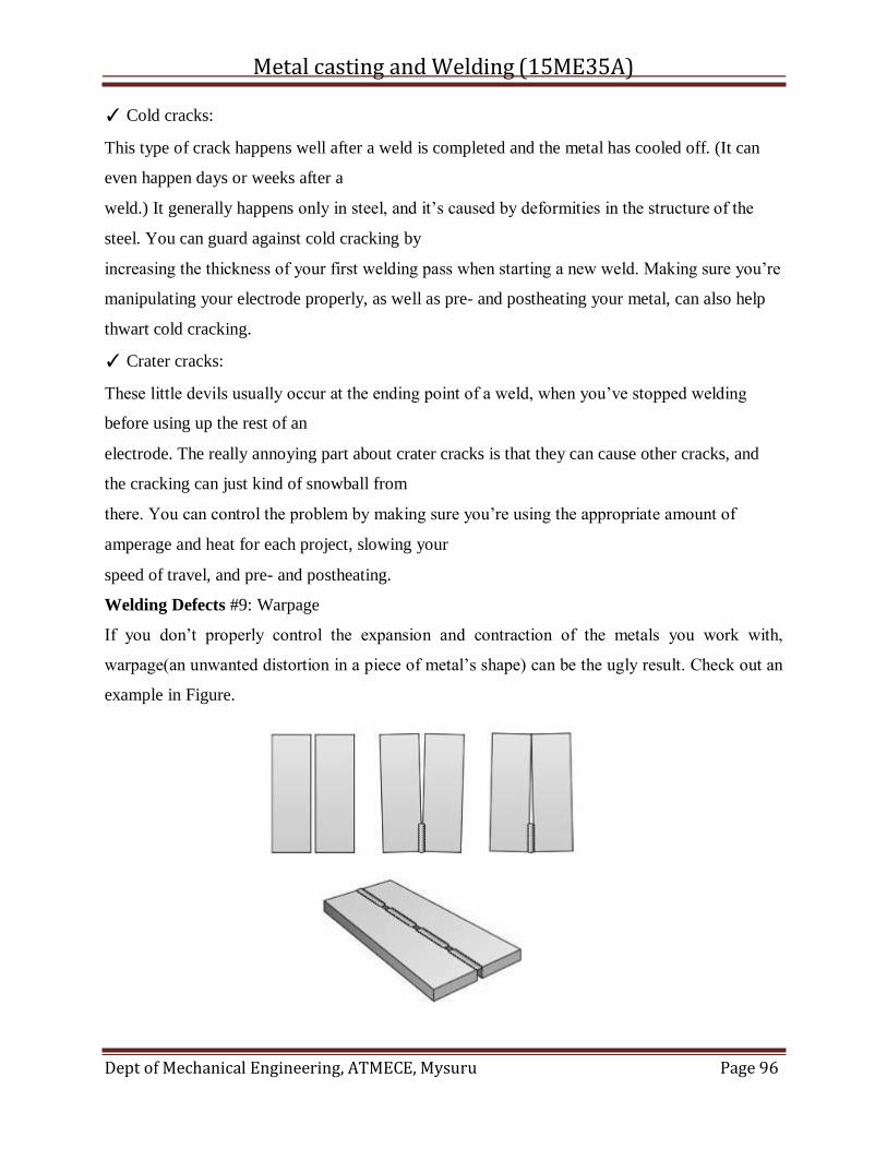
Metal casting and Welding (15ME35A)
Dept of Mechanical Engineering, ATMECE, Mysuru Page 96
✓ Cold cracks:
This type of crack happens well after a weld is completed and the metal has cooled off. (It can
even happen days or weeks after a
weld.) It generally happens only in steel, and it’s caused by deformities in the structure of the
steel. You can guard against cold cracking by
increasing the thickness of your first welding pass when starting a new weld. Making sure you’re
manipulating your electrode properly, as well as pre- and postheating your metal, can also help
thwart cold cracking.
✓ Crater cracks:
These little devils usually occur at the ending point of a weld, when you’ve stopped welding
before using up the rest of an
electrode. The really annoying part about crater cracks is that they can cause other cracks, and
the cracking can just kind of snowball from
there. You can control the problem by making sure you’re using the appropriate amount of
amperage and heat for each project, slowing your
speed of travel, and pre- and postheating.
Welding Defects #9: Warpage
If you don’t properly control the expansion and contraction of the metals you work with,
warpage(an unwanted distortion in a piece of metal’s shape) can be the ugly result. Check out an
example in Figure.
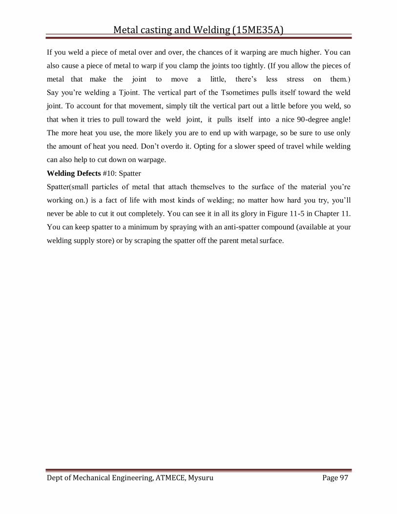
Metal casting and Welding (15ME35A)
Dept of Mechanical Engineering, ATMECE, Mysuru Page 97
If you weld a piece of metal over and over, the chances of it warping are much higher. You can
also cause a piece of metal to warp if you clamp the joints too tightly. (If you allow the pieces of
metal that make the joint to move a little, there’s less stress on them.)
Say you’re welding a Tjoint. The vertical part of the Tsometimes pulls itself toward the weld
joint. To account for that movement, simply tilt the vertical part out a litt le before you weld, so
that when it tries to pull toward the weld joint, it pulls itself into a nice 90-degree angle!
The more heat you use, the more likely you are to end up with warpage, so be sure to use only
the amount of heat you need. Don’t overdo it. Opting for a slower speed of travel while welding
can also help to cut down on warpage.
Welding Defects #10: Spatter
Spatter(small particles of metal that attach themselves to the surface of the material you’re
working on.) is a fact of life with most kinds of welding; no matter how hard you try, you’ll
never be able to cut it out completely. You can see it in all its glory in Figure 11-5 in Chapter 11.
You can keep spatter to a minimum by spraying with an anti-spatter compound (available at your
welding supply store) or by scraping the spatter off the parent metal surface.
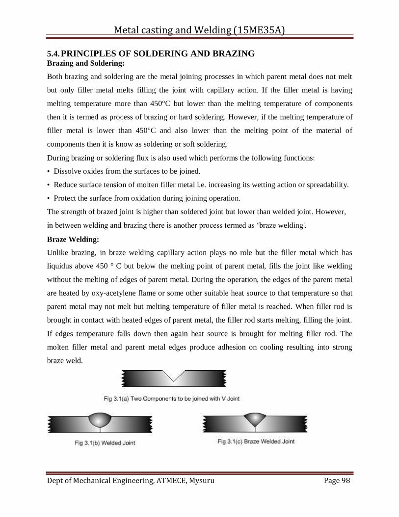
Metal casting and Welding (15ME35A)
Dept of Mechanical Engineering, ATMECE, Mysuru Page 98
5.4. PRINCIPLES OF SOLDERING AND BRAZING Brazing and Soldering:
Both brazing and soldering are the metal joining processes in which parent metal does not melt
but only filler metal melts filling the joint with capillary action. If the filler metal is having
melting temperature more than 450°C but lower than the melting temperature of components
then it is termed as process of brazing or hard soldering. However, if the melting temperature of
filler metal is lower than 450°C and also lower than the melting point of the material of
components then it is know as soldering or soft soldering.
During brazing or soldering flux is also used which performs the following functions:
• Dissolve oxides from the surfaces to be joined.
• Reduce surface tension of molten filler metal i.e. increasing its wetting action or spreadability.
• Protect the surface from oxidation during joining operation.
The strength of brazed joint is higher than soldered joint but lower than welded joint. However,
in between welding and brazing there is another process termed as ‘braze welding'.
Braze Welding:
Unlike brazing, in braze welding capillary action plays no role but the filler metal which has
liquidus above 450 ° C but below the melting point of parent metal, fills the joint like welding
without the melting of edges of parent metal. During the operation, the edges of the parent metal
are heated by oxy-acetylene flame or some other suitable heat source to that temperature so that
parent metal may not melt but melting temperature of filler metal is reached. When filler rod is
brought in contact with heated edges of parent metal, the filler rod starts melting, filling the joint.
If edges temperature falls down then again heat source is brought for melting filler rod. The
molten filler metal and parent metal edges produce adhesion on cooling resulting into strong
braze weld.
Metal casting and Welding (15ME35A)
Dept of Mechanical Engineering, ATMECE, Mysuru Page 99
The braze welding filler material is normally brass with 60% Cu and remaining Zn with small
additions of tin, manganese and silicon. The small additions of elements improve the deoxidizing
and fluidity characteristics of filler metal.
Brazing:
The most commonly used filler metal is copper base zinc alloy consisting of normally 50-60%
Cu, approximately 40% Zn, 1% Ni, 0.7 % Fe and traces of Si and Mn, which is brass and termed
as 'spelter'. In some cases around 10% Ni may also be added to filler alloys. Copper base alloys
may be available in the form of rod, strip and wire. Silver brazing filler metal may consists of 30-
55% Ag, 15-35% Cu, 15-28% Zn, 18-24% Cd and sometimes 2-3% Ni or 5% Sn. Silver brazing
alloys are available in form of wire, strip, rods and powders.
Borax and boric acid are commonly used fluxes for brazing with copper base filler metals. Many
other commercial fluxes may be available in the form of paste or liquid solution leading to ease
of application and adherence to the surface in any position.
Various commonly used method of brazing are followings:
• Torch Brazing
Torch brazing utilizes the heat of oxy-acetylene flame with neutral or reducing flame. Filler
metal may be either preplaced in form of washers, rings, formed strips, powders or may be fed
manually in form of rod.
• Dip Brazing
In dip brazing components with filler metal in proper form is preplaced at the joint and assembly
is dipped in bath of molten salt which acts as heat source as well as flux for brazing. Preplaced
preform melts and fills the joint. Another variant is to dip assembled parts in metallic bath and
metal of bath fills the joint.
• Furnace Brazing
Self fixturing assembly with preplaced filler metal is placed inside electrically heated furnace
with temperature control for heating and cooling. These furnaces may also be using protective
atmosphere with inert gases like argon and helium or vacuum for brazing of reactive metal
components.
• Infra-red Brazing
The heat for brazing is obtained from infra-red lamps. Heat rays can be concentrated at desired
area or spot with concave reflectors. Such method of brazing requires automation and parts to be
Metal casting and Welding (15ME35A)
Dept of Mechanical Engineering, ATMECE, Mysuru Page 100
joined should be self fixturing. Filler metal is to be preplaced in the joint. The operation can be
performed in air or in inert atmosphere or in vacuum.
• Induction Brazing
The heat is generated by induced current into the workpiece from a water cooled coil which
surrounds the workpieces to be brazed. High frequencies employed vary from 5 to 400 kHz.
Higher the frequency of current, shallow is the heating effect while lower frequencies of current
lead to deeper heating and so it can be employed for thicker sections. Fluxes may or may not be
used during brazing.
• Resistance Brazing
In resistance brazing the heat is generated at the interfaces to be brazed by resistive heating. The
components are connected to high current and low voltage power supply through two electrodes
under pressure. Only those fluxes are used which are electrically conductive and filler metal is
preplaced.
Fig 3.2: Typical Self Fixturing Brazing Assembly
The soldering filler metal is called solder. The most commonly used solder is lead and tin alloy
containing tin ranging from 5 to 70% and lead 95 to 30%. Higher the contents of tin, lower the
melting point of alloy. Other filler metal are tin-antimony solder (95% tin and 5% antimony), tin-
silver solder (tin 96% and silver 4%), lead-silver solder (97% lead, 1.5 tin and 1.5 silver), tin-
zinc solder (91 to 30% tin and 9 to 70% zinc), cadmium-silver solder (95% cadmium and 5%
silver). These are available in the form of bars, solid and flux cored wires, preforms, sheet, foil,
ribbon and paste or cream.
Fluxes used in soldering are ammonium chloride, zinc chloride, rosin and rosin dissolved in
alcohol.
Various soldering methods are soldering with soldering irons, dip soldering, torch soldering,
oven soldering, resistance soldering, induction soldering, infra-red and ultrasonic soldering.
Soldering iron being used for manual soldering, consists of insulated handle and end is fitted
with copper tip which may be heated electrically or in coke or oil/gas fired furnace. Solder is
Metal casting and Welding (15ME35A)
Dept of Mechanical Engineering, ATMECE, Mysuru Page 101
brought to molten state by touching it to the tip of the soldering iron so that molten solder can
spread to the joint surface.
Ultrasonic soldering uses ultrasonics i.e. high frequency vibrations which break the oxides on the
surface of workpieces and heat shall be generated due to rubbing between surfaces. This heat
melts the solder and fills the joint by capillary action.
Flux Residue Treatment:
When brazing or soldering is completed then the flux residues are to be removed because
without removal the residues may lead to corrosion of assemblies.
Brazing flux residues can be removed by rinsing with hot water followed by drying. If the
residue is sticky then it can be removed by thermal shock i.e. heating and quenching. Sometimes
steam jet may be applied followed by wire brushing.
Soldering flux residues of rosin flux can be left on the surface of joint, however, activated rosin
flux and other flux residues require proper treatment. If rosin residues removal is required then
alcohol, acetone or carbon tetrachloride can be used. Organic flux residues are soluble in hot
water so double rising in warm water shall remove it. Residue removal of zinc chloride base
fluxes can be achieved by washing first in 2% hydrochloric acid mixed in hot water followed by
simple hot water rinsing.
Following is the detail of each item of visual inspection as listed above.
1. Welders certificate — The first thing that an on-site weld inspector is expected to check is
whether or not the welder selected to perform the welding has passed the required tests and
carries the relevant certification. A Welder Procedure Qualification (WPQ) test is established
with respect to the Welding Procedure Specification (WPS) submitted by the contractor at the
time of tendering the project. All the project welders are required to pass a welder performance
test with respect to this (WPQ). Besides the individual’s name and photograph, the type of test
passed is also indicated on this card. The thickness and diameter range of pipe a welder is
certified to weld is also mentioned.
The welding inspector can ask any welder to produce this certificate on demand. No welder,
however expert, is allowed to perform a welding task without this card. Welders discovered to be
welding without this card not only are to be removed from the site but the project contractor too
should be reprimanded.
Metal casting and Welding (15ME35A)
Dept of Mechanical Engineering, ATMECE, Mysuru Page 102
2. Weld joint preparation — Although both the fabricator and welder both know the material to
be welded and the joint to be prepared for welding, it is also the duty of a welding inspector to
double-check each and every joint to ascertain that it has been prepared according to an agreed
standard. In the case of a pipe joint he should check the root gap, root lap, and the weld angle.
Also, he should check the thickness and pipe diameter range a specific welder is supposed to
weld before welding begins.
3. Electrode condition — The welding electrode, its size, and its physical condition is another
important aspect of visual welding inspection. High-quality welds cannot be produced with poor
electrodes. Besides quality, the diameter of the electrode should be inspected according to the
welding procedure qualification. Current and voltage required for welding are also adjusted
according to the diameter of an electrode. Care must be taken that the right type of electrode is
used to weld a specific joint. Wet electrodes and electrodes with rusted tips cannot produce good
welds.
In the case of a low-hydrogen electrode, preheating of electrodes to a certain temperature range
is required before use. Preheating of low-hydrogen electrodes is done in specific ovens. Also, a
code to specify the strength should be clearly written on each electrode for easy identification.
4. Welding technique — next comes the welding technique or welding method to be used for
the movement of the electrode, especially on pipes. A “down hand” (downhill) technique is used
on cross-country pipelines and “up hand” (uphill) technique is used on plant piping. With the
down-hand welding technique the electrode is moved from top to bottom of a pipe during
welding, and in up-hand welding the motion is in the reverse. It is easier for welders to weld with
a down-hand technique than with than with up-hand technique. Care must be taken so that
welders use the right welding technique.
5. Weather conditions — another required factor that cannot be detected by radiography or
other weld-quality control methods, except by visual inspection, are if the welds were made
during bad weather. Special protective measures like use of tarpaulin covers are used to protect
welds from rain, dust storms and high-velocity wind, etc. Good quality welds cannot be
produced in bad weather conditions.
6. Welding current — by visual inspection one can check polarity, amperage, and voltage
during welding operation. One cannot check these parameters through any other quality control
method. Reverse polarity is used on pipe welding. In reverse polarity, the electrode is positive
Metal casting and Welding (15ME35A)
Dept of Mechanical Engineering, ATMECE, Mysuru Page 103
and the pipe is negative Care must be taken to ensure that the correct polarity, correct amperage,
and voltage are used for welding. A welding inspector will have the necessary tool to check
current during welding operation.
7. Welding machines, tools — to ensure a good job it is imperative to have good tools, which is
true also for welding. Visual welding inspection also includes the inspection of the following
tools: ;
• Welding machine; ;
• Grinding machine; ;
• Welding cables; ;
• Welding clamps; ;
• Internal and external pipe clamps; ;
• Brushes; ;
• Welding helmet and glasses.
The welding machine is even more important. It should be able to produce the desired current
and voltage properly. Ampere meters are used by welding inspectors to measure current during
welding.
8. Slag cleaning — Coating on the electrode, which saves the molten metal from rusting during
welding by producing slag cover, must be cleaned with the help of a grinder after the completion
of each pass to achieve good quality weld. Visual inspection helps in this regard tremendously.
9. Incomplete welds — the welding inspector conducting welding inspection should check that
no weld is left incomplete at the end of the day.
10. Selection for radiography — because the welding inspector is always present during a
welding operation, he is the best person to decide which welds are to be radiographed (if certain
percentages of welds are to selected for radiography.) Moreover, he can determine if a certain
weld that had a defect during radiography has been properly repaired, and re-radiographed and
cleared.
5.5. Magnetic particle Inspection (MPI) is a non-destructive testing (NDT) process for
detecting surface and slightly subsurface discontinuities in ferromagnetic materials such
as iron, nickel, cobalt, and some of their alloys. The process puts a magnetic field into the part.
The piece can be magnetized by direct or indirect magnetization. Direct magnetization occurs
when the electric current is passed through the test object and a magnetic field is formed in the
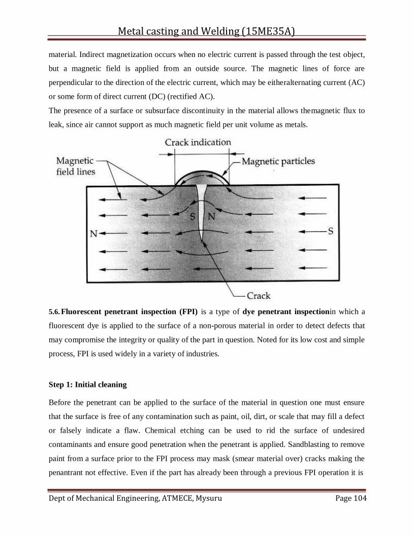
Metal casting and Welding (15ME35A)
Dept of Mechanical Engineering, ATMECE, Mysuru Page 104
material. Indirect magnetization occurs when no electric current is passed through the test object,
but a magnetic field is applied from an outside source. The magnetic lines of force are
perpendicular to the direction of the electric current, which may be eitheralternating current (AC)
or some form of direct current (DC) (rectified AC).
The presence of a surface or subsurface discontinuity in the material allows themagnetic flux to
leak, since air cannot support as much magnetic field per unit volume as metals.
5.6. Fluorescent penetrant inspection (FPI) is a type of dye penetrant inspectionin which a
fluorescent dye is applied to the surface of a non-porous material in order to detect defects that
may compromise the integrity or quality of the part in question. Noted for its low cost and simple
process, FPI is used widely in a variety of industries.
Step 1: Initial cleaning
Before the penetrant can be applied to the surface of the material in question one must ensure
that the surface is free of any contamination such as paint, oil, dirt, or scale that may fill a defect
or falsely indicate a flaw. Chemical etching can be used to rid the surface of undesired
contaminants and ensure good penetration when the penetrant is applied. Sandblasting to remove
paint from a surface prior to the FPI process may mask (smear material over) cracks making the
penantrant not effective. Even if the part has already been through a previous FPI operation it is
Metal casting and Welding (15ME35A)
Dept of Mechanical Engineering, ATMECE, Mysuru Page 105
imperative that it is cleaned again. Most penetrants are not compatible and therefore will thwart
any attempt to identify defects that are already penetrated by any other penetrant. This process of
cleaning is critical because if the surface of the part is not properly prepared to receive the
penetrant, defective product may be moved on for further processing. This can cause lost time
and money in reworking, overprocessing, or even scrapping a finished part at final inspection.
Step 2: Penetrant application
The fluorescent penetrant is applied to the surface and allowed time to seep into flaws or defects
in the material. The process of waiting for the penetrant to seep into flaws is called Dwell Time.
Dwell time varies by material and the size of the indications that are intended to be identified but
is generally less than 30 minutes. It requires much less time to penetrate larger flaws because the
penetrant is able to soak in much faster. The opposite is true for smaller flaws/defects.
Step 3: Excess penetrant removal
After the identified dwell time has passed, penetrant on the outer surface of the material is then
removed. This highly controlled process is necessary in order to ensure that the penetrant is
removed only from the surface of the material and not from inside any identified flaws. Various
chemicals can be used for such a process and vary by specific penetrant types. Typically, the
cleaner is applied to a lint-free cloth that is used to carefully clean the surface.
Step 4: Developer application
Having removed excess penetrant a contrasting developer may be applied to the surface. This
serves as a background against which flaws can more readily be detected. The developer also
causes penetrant that is still in any defects to surface and bleed. These two attributes allow
defects to be easily detected upon inspection. Dwell time is then allowed for the developer to
achieve desired results before inspection.
Step 5: Inspection
In the case of fluorescent inspection, the inspector will use ultraviolet radiation with an intensity
appropriate to the intent of the inspection operation. This must take place in a dark room to
ensure good contrast between the glow emitted by the penetrant in the defected areas and the
unlit surface of the material. The inspector carefully examines all surfaces in question and
records any concerns. Areas in question may be marked so that location of indications can be
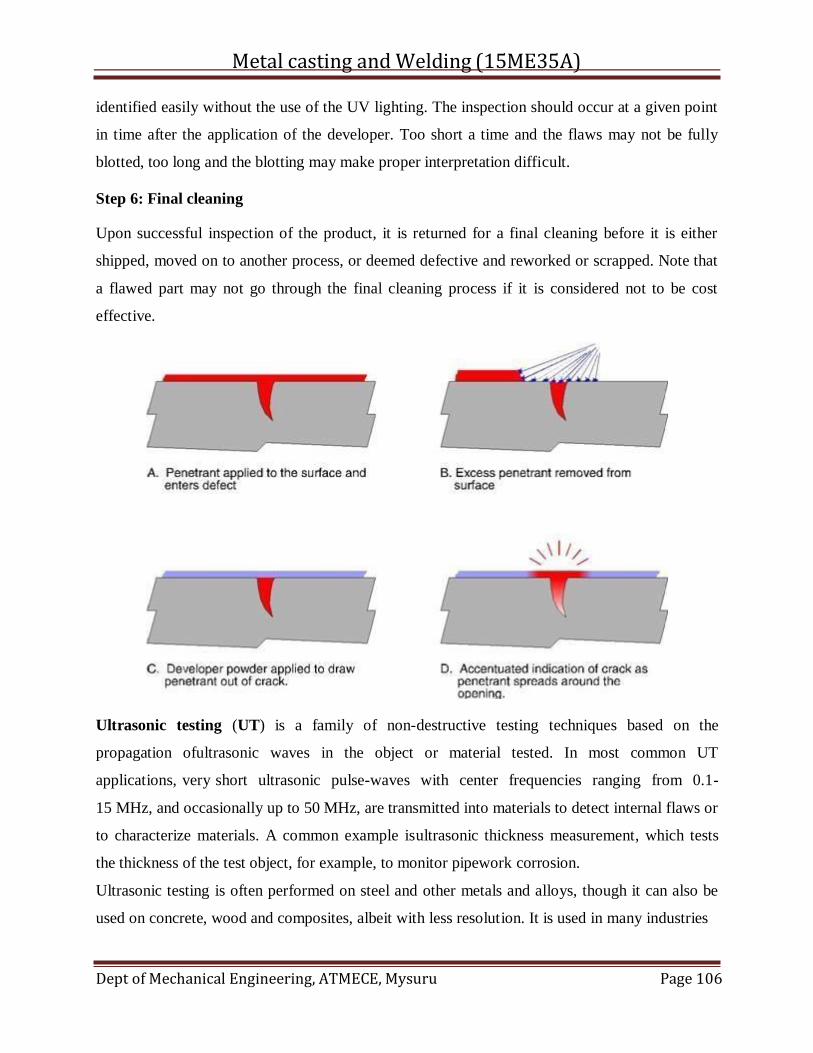
Metal casting and Welding (15ME35A)
Dept of Mechanical Engineering, ATMECE, Mysuru Page 106
identified easily without the use of the UV lighting. The inspection should occur at a given point
in time after the application of the developer. Too short a time and the flaws may not be fully
blotted, too long and the blotting may make proper interpretation difficult.
Step 6: Final cleaning
Upon successful inspection of the product, it is returned for a final cleaning before it is either
shipped, moved on to another process, or deemed defective and reworked or scrapped. Note that
a flawed part may not go through the final cleaning process if it is considered not to be cost
effective.
Ultrasonic testing (UT) is a family of non-destructive testing techniques based on the
propagation ofultrasonic waves in the object or material tested. In most common UT
applications, very short ultrasonic pulse-waves with center frequencies ranging from 0.1-
15 MHz, and occasionally up to 50 MHz, are transmitted into materials to detect internal flaws or
to characterize materials. A common example isultrasonic thickness measurement, which tests
the thickness of the test object, for example, to monitor pipework corrosion.
Ultrasonic testing is often performed on steel and other metals and alloys, though it can also be
used on concrete, wood and composites, albeit with less resolution. It is used in many industries
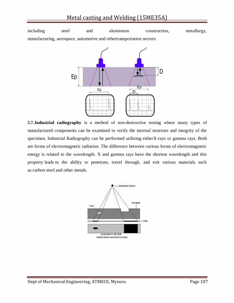
Metal casting and Welding (15ME35A)
Dept of Mechanical Engineering, ATMECE, Mysuru Page 107
including steel and aluminium construction, metallurgy,
manufacturing, aerospace, automotive and othertransportation sectors.
5.7. Industrial radiography is a method of non-destructive testing where many types of
manufactured components can be examined to verify the internal structure and integrity of the
specimen. Industrial Radiography can be performed utilizing eitherX-rays or gamma rays. Both
are forms of electromagnetic radiation. The difference between various forms of electromagnetic
energy is related to the wavelength. X and gamma rays have the shortest wavelength and this
property leads to the ability to penetrate, travel through, and exit various materials such
as carbon steel and other metals.
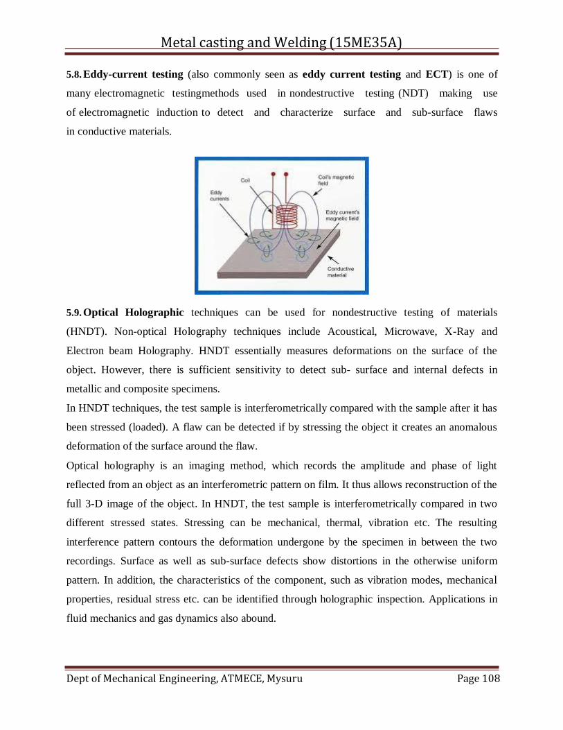
Metal casting and Welding (15ME35A)
Dept of Mechanical Engineering, ATMECE, Mysuru Page 108
5.8. Eddy-current testing (also commonly seen as eddy current testing and ECT) is one of
many electromagnetic testingmethods used in nondestructive testing (NDT) making use
of electromagnetic induction to detect and characterize surface and sub-surface flaws
in conductive materials.
5.9. Optical Holographic techniques can be used for nondestructive testing of materials
(HNDT). Non-optical Holography techniques include Acoustical, Microwave, X-Ray and
Electron beam Holography. HNDT essentially measures deformations on the surface of the
object. However, there is sufficient sensitivity to detect sub- surface and internal defects in
metallic and composite specimens.
In HNDT techniques, the test sample is interferometrically compared with the sample after it has
been stressed (loaded). A flaw can be detected if by stressing the object it creates an anomalous
deformation of the surface around the flaw.
Optical holography is an imaging method, which records the amplitude and phase of light
reflected from an object as an interferometric pattern on film. It thus allows reconstruction of the
full 3-D image of the object. In HNDT, the test sample is interferometrically compared in two
different stressed states. Stressing can be mechanical, thermal, vibration etc. The resulting
interference pattern contours the deformation undergone by the specimen in between the two
recordings. Surface as well as sub-surface defects show distortions in the otherwise uniform
pattern. In addition, the characteristics of the component, such as vibration modes, mechanical
properties, residual stress etc. can be identified through holographic inspection. Applications in
fluid mechanics and gas dynamics also abound.
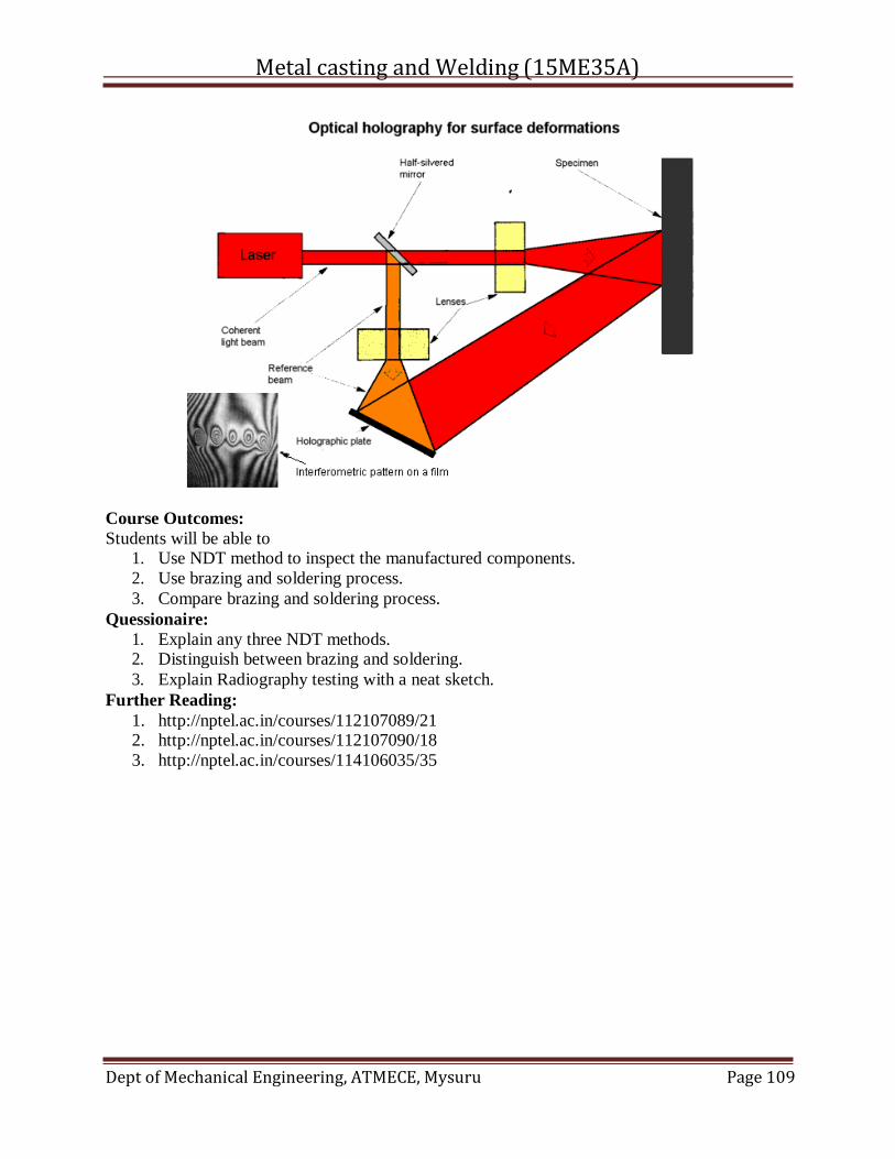
Metal casting and Welding (15ME35A)
Dept of Mechanical Engineering, ATMECE, Mysuru Page 109
Course Outcomes:
Students will be able to 1. Use NDT method to inspect the manufactured components.
2. Use brazing and soldering process.
3. Compare brazing and soldering process.
Quessionaire:
1. Explain any three NDT methods. 2. Distinguish between brazing and soldering.
3. Explain Radiography testing with a neat sketch.
Further Reading:
1. http://nptel.ac.in/courses/112107089/21 2. http://nptel.ac.in/courses/112107090/18
3. http://nptel.ac.in/courses/114106035/35