Embed Size (px)
Citation preview
Friction Stir Welding Laboratory
Casting Forming and Welding Lab (ME39007)
Experiment No. 4: Friction Stir Welding
Objectives:
To perform friction stir welding (FSW) on two similar aluminum sheets of same gauge by varying
the FSW tool rotational and worktable translational speeds.
To analyse the influence of spindle tilt on surface defect (like amount of flash formation, weld root
defects, etc.) by visual examination.
To study the influence of FSW tool rotational and worktable translation speed (i.e. welding speed),
on welding force (Fx), axial force (Fz) and power consumption.
Instruments required:
Numerically controlled FSW machine having load cell attached to it (to measure force and torque
during welding),
Fixture for clamping the workpiece on the machine table,
Al sheets of dimensions (100 50 2.5 mm3),
FSW tool (having flat shoulder surface and straight circular pin),
Few others necessary equipments for tightening and loosing the desired nuts and bolts.
Hurdles in Welding Aluminum:
Difference of hydrogen solubility in liquid and solid state of aluminium alloy, leads to hydrogen
trapping inside the weld and formation of defects like blow holes, porosity etc.
Formation of aluminium oxide on exposed surface, which is non-conductive, hard and has high
melting point (approx 1900oC).
High thermal conductivity as compared to steel, which causes rapid heat distribution due to
conduction within the material
High thermal expansion (almost twice of steel) and high shrinkage volume (approx 6% of volume)
increases distortion and weld crater size.
Though various techniques like MIG, TIG, rotary friction welding is used for welding aluminum alloy but
none of them could provide high weld strength required for aerospace or marine industries due to high Heat
affect zone (HAZ), distortion etc. To achieve high weld strength friction stir welding was developed at The
Welding Institute (TWI), UK in 1991 [1].
Theory of FSW
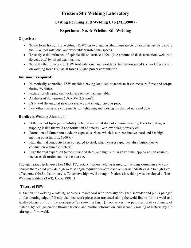
In friction stir welding a rotating non-consumable tool with specially designed shoulder and pin is plunged
on the abutting edge of firmly clamped work piece than traversed along the weld line to form a weld and
finally plunge out from the work-piece (as shown in Fig. 1). Tool serves two purposes, firstly softening of
material by heat generation through friction and plastic deformation, and secondly mixing of material by pin
stirring to form weld.
The side of the workpiece where the tool rotation and tool translation vectors are same, is called
advancing side (AS); and the side where the tool rotation and translation vectors remain opposite is called
retreating side (RS). Furthermore, a typical friction stir welding cross-section consists of four micro-
structural zones; namely stirred zone or nugget zone (NZ), thermo-mechanically affected zone (TMAZ),
heat affected zone (HAZ) and unaffected or base metal zone (BM). Threadgill [2] gave the nomenclature to
different FSW zones. The stirred zone is the region where the work-piece material gets stirred due to
influence of both rotary shoulder and pin. Obviously, materials at this zone remain subjected to high strain,
high strain rate and higher temperature (due to heating by both friction and large plastic deformation).
TMAZ is subjected to heat and some inertia of the materials from the NZ (which causes grain orientation)
and material in HAZ is subjected to heat. Temperature in HAZ is less as compared to HAZ of fusion
welding. After HAZ the region which remains unaffected is called base metal.
Mechanics of material flow:
Nature of material flow during FSW is extreme complex and very difficult to clearly understood.
However, most of the researchers agreed that the material flows from the leading edge of the tool to the
trailing edge through retreating side (RS); and at last, centrifugally forged into the advancing side (AS).
They justify this concept by reporting that, whenever there occurs some significant material loss (either by
excessive flash or by some other means) the total amount of material required to be forged in the AS finds
lacking; and hence, defects like groove and tunnel formation always takes place only in the AS.
Mechanism of heat generation and stabilization during FSW:
The mechanical work-done by the FSW tool on the work-piece (both by the frictional rubbing and
materials stirring) gets converted into heat; according to law of conservation of energy. This heat generation
raises the work-piece temperature. With increase in work-piece temperature, the yield strength of the
material decreases. Therefore, less work is required for further plasticizing of material and rate of heat
generation decreases. This results in decrease in temperature; and hence, this mechanism stabilizes the
temperature during FSW and avoids melting of the material.
Mechanics of defect formation:
Surface flash, root flaws and worm holes are the defects which occur most often in FSW; however,
few other defects like surface galling, nugget collapse, kissing bond etc. are also occur time to time.
Appendix-II provides detail on these defects. In general, as the FSW tool is plunged into the material; a key
hole is formed, and work-piece material starts stirring around it. When, the tool starts to travel along the
Fig. 1 Basic steps involved in a FSW (left side), and various micro-structural zones in a
typical FSW cross-section (right side); [2]
welding line; the hot plasticized stirring material is forged into the key hole generated due to pin travel.
Thus, improper choice of FSW parameters and/or lack of axial pressure (beneath of the FSW tool shoulder)
leads to defect formation. Zhang et al. [3] proposed a mathematical model and formulated a relation among
axial pressure, tool rotational speed and work-table translational speed, in order to get a defect free weld.
The relation is given below, (for complete derivation of the relation, please see the appendix-II).
� ∗ ����� ≥ �
����������� −�����
Where, P is the axial pressure, �����is the inverse of welding rate, V is the volume of the key hole, k is a
constant depends on the material properties and weld temperature, ��������� and ���� represent radius of tool
shoulder and pin, respectively. According to this relation for a particular FSW tool, the weld speed must be
less than a specific value, when the axial pressure and tool rotational speed are kept constant; and/or if
welding speed is kept constant, then the axial pressure and tool rotational speed must be larger than a
specific value, in order to achieve a defect free weld.
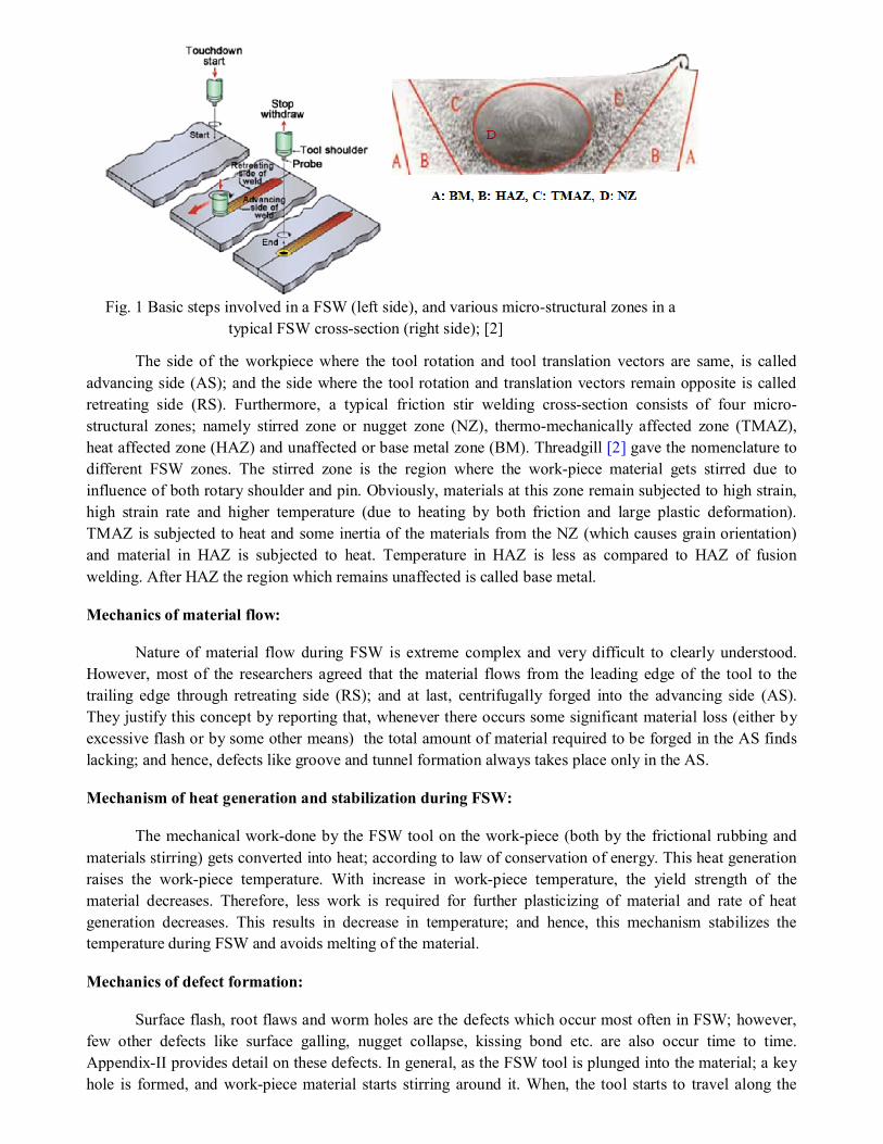
Experimental procedure:
1. Switch on the MCB switch (electric input to the machine), On/Off switch on the machine body at the
left side and start the computer monitor attached with the machine.
2. Then, double click on the ‘stir welding’ icon on the desktop in order to start the software. Once the
software gets started; it will ask for pressing hydraulic knob for switching it on, and then for spindle
home.
3. Fix the FSW tool into the spindle through proper dimension of collet, and then tight the adapter nut
using semicircle spanner.
4. Place the work-piece on the anvil of machine work-table. Make sure the sheets are being placed in
such a manner that the joining line is parallel to the machine X-axis, and then clamp the work-piece
using bolts.
5. Once it will be done, choose the ‘manual mode’ option from the available options. Insert suitable
values for work-table movement, and move the work-table against fixed FSW tool for obtaining the
Xstart, Xend and Zend position values. Here, Xstart, Xend denotes start and end point of welding on the work-
piece clamped, and Zend position denotes the point up to which the FSW tool will reach during plunging.
6. Come out from the ‘manual mode’ and then go to the ‘parameter’ for specifying the parameters for
weld to be conducted. If required change the spindle tilt angle.
7. After specifying the parameters go to the ‘auto mode’ and click on icon ‘continue’, to start the weld.
But, before pressing ‘cycle on’ switch, make sure that the coolant pump for spindle is switched on.
8. After finishing of the weld, switch off the coolant pump, and hydraulic knob.
Table1 Work-piece and tool dimensions
Fig. 2 Work-piece with process parameter details
Work-piece dimension (length × width, mm2 ) Tool shoulder diameter (mm)
Tool pin profile Tool pin diameter (mm) Tool pin height (mm)
Work-piece sheet thickness (mm) Plunge depth (mm)
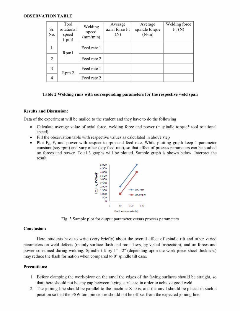
OBSERVATION TABLE
Sr. No.
Tool rotational
speed (rpm)
Welding speed
(mm/min)
Average axial force Fz
(N)
Average spindle torque
(N-m)
Welding force Fx (N)
1. Rpm1
Feed rate 1
2 Feed rate 2
3 Rpm 2
Feed rate 1
4 Feed rate 2
Table 2 Welding runs with corresponding parameters for the respective weld span
Results and Discussion:
Data of the experiment will be mailed to the student and they have to do the following
Calculate average value of axial force, welding force and power (= spindle torque* tool rotational speed).
Fill the observation table with respective values as calculated in above step Plot Fz, Fx and power with respect to rpm and feed rate. While plotting graph keep 1 parameter
constant (say rpm) and vary other (say feed rate), so that effect of process parameters can be studied on forces and power. Total 3 graphs will be plotted. Sample graph is shown below. Interpret the result
Fig. 3 Sample plot for output parameter versus process parameters
Conclusion:
Here, students have to write (very briefly) about the overall effect of spindle tilt and other varied
parameters on weld defects (mainly surface flash and root flaws, by visual inspection), and on forces and
power consumed during welding. Spindle tilt by 1º - 2º (depending upon the work-piece sheet thickness)
may reduce the flash formation when compared to 0º spindle tilt case.
Precautions:
1. Before clamping the work-piece on the anvil the edges of the faying surfaces should be straight, so
that there should not be any gap between faying surfaces; in order to achieve good weld.
2. The joining line should be parallel to the machine X-axis, and the anvil should be placed in such a
position so that the FSW tool pin centre should not be off-set from the expected joining line.
3. When coming out from the manual mode, move the spindle up in the Z-axis; otherwise while
selecting auto mode the spindle will directly move to the last Z-value the spindle had in the manual
mode.
4. Before pressing the ‘cycle on’ knob in the monitor panel the work-piece should be rigidly clamped
on the anvil, and the allen bolts (placed at the right bottom side of the anvil) must be tightened in
order to prevent the vibration of anvil along Y-axis
Benefits of using FSW:
There are a number of benefits of using FSW [4]; however, only few important benefits are
addressed here.
1. No distortion of the work-piece takes place; since the process occurs at the solid state. Also, better
dimensional accuracy, better surface finish, and less softening at the HAZ are achieved; which
results in better weld strength.
2. Due to continuous dynamic recrystallization, fine equiaxed grains are developed in the stirred region,
which further improves the mechanical and metallurgical properties of the weld.
3. Since no consumable is used, so the weld composition remain same as the base metal; hence,
problems associated with the compositional change remain completely absent here.
4. Since no fumes and no harmful rays are generated, and also no shielding gas is required; so the
process is environment as well as operator friendly.
5. The process is energy efficient, because relatively less energy is required in FSW when compared to
other welding processes (like laser, plasma and electron beam welding).
6. It reduces the fuel consumption, because the process is widely being used in aerospace, automotive,
shipbuilding and marine industries to fabricate less weight component, which reduce the fuel
consumption.
7. Very good scope for repeatability, as the process is easy to automate.
Limitations of FSW:
1. At the end of welding a pin hole remains present in the region where the tool is plunge out. This
leads to some amount of material loss.
2. Significant thinning takes place at the weld region due to formation of ribbon flash.
3. The process requires adequate reaction force from the bottom side for producing sound weld; so, use
of backing plate is must.
4. Sufficient clamping force is also required in order to oppose the abutting force. Because of that
completely elimination of residual stress is still difficult.
Applications of FSW:
There are a number of fields where friction stir welding is being utilized for fabrication of various
parts [5]. However, few main areas are listed below.
Aerospace industry
1. Wings, fuselages
2. Cryogenic fuel tanks for space vehicles
3. Aviation fuel tanks
4. Repair of faulty MIG welds
Railway industry
1. Rolling stock of railways, underground carriages, trams
2. Railway tankers and goods wagons
Automotive industries
1. Engine and chassis cradles, Body-in-white structure, Tailor welded blanks
2. Wheel rims
3. Truck bodies, Tail lifts for lorries, Armour plate vehicles
4. Fuel tankers
Shipbuilding and marine Industries
1. Panels for decks, sides, bulkheads and floors
2. Boat sections
3. Helicopter landing platforms
4. Marine structures
Construction industries
1. Aluminium bridge
2. Window frames
3. Aluminium pipelines
4. Heat exchangers and air conditioners, using Friction Stir Channelling
Electrical industries:
1. Electric motor housings 2. Bush bars 3. Electrical connectors
Electronics industries:
1. Apple next generation iMac [6]
Questions:
Q1. What is the significance of plunge force or axial force in FSW? Q2. How does the temperature stabilization occur in FSW? Q3. What is the role of welding speed on defect formation in FSW? Q4. Why does the weld power increases with increase in tool rotational speed?
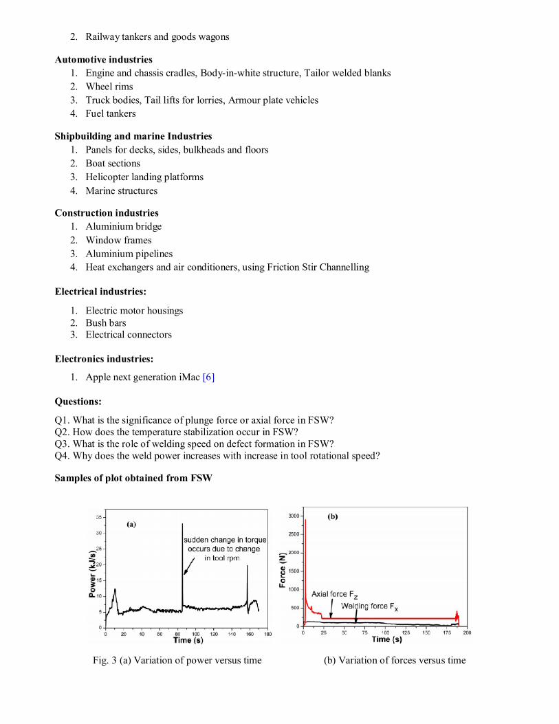
Samples of plot obtained from FSW
Fig. 3 (a) Variation of power versus time (b) Variation of forces versus time
7
References:
[1] W. M. Thomas, E. D. Nicholas, J. C. Needham, M. G. Murch, S. P. Temple, and C. J. Dawes, “Friction stir butt welding,” PCT/GB92/022031991.
[2] H. Jin, C. Ko, S. Saimoto, and P. L. Threadgill, “Microstructure of Friction Stir Welded Joints in AA5182,” Mater. Sci. Forum, vol. 331–337, pp. 1725–1730, 2000.
[3] H. Zhang, S. B. Lin, L. Wu, J. C. Feng, and S. L. Ma, “Defects formation procedure and mathematic model for defect free friction stir welding of magnesium alloy,” Mater. Des., vol. 27, no. 9, pp. 805–809, 2006.
[4] R. S. Mishra and Z. Y. Ma, “Friction stir welding and processing,” Mater. Sci. Eng. R Reports, vol. 50, no. 1–2, pp. 1–78, 2005.
[5] R. Nandan, T. Debroy, and H. Bhadeshia, “Recent advances in friction-stir welding – Process, weldment structure and properties,” Prog. Mater. Sci., vol. 53, no. 6, pp. 980–1023, Aug. 2008.
[6] Apple, “Website addresses,” 2013. [Online]. Available: https://www.apple.com/in/imac/design/.
I
Appendix-I Parameters affecting Friction Stir Weld
Simply knowing physics of the process and mechanics of weld formation are not
enough; but, the proper understanding of effects of various parameters affecting FSW
process, and various defects occurs in a FSW, their causes and remedies are also essential in
order to produce good quality welds. Here (in appendix-I) a little explore is being given on
those various influencing parameters. Causes and remedies of various FSW defects will be
explored in the next appendix.
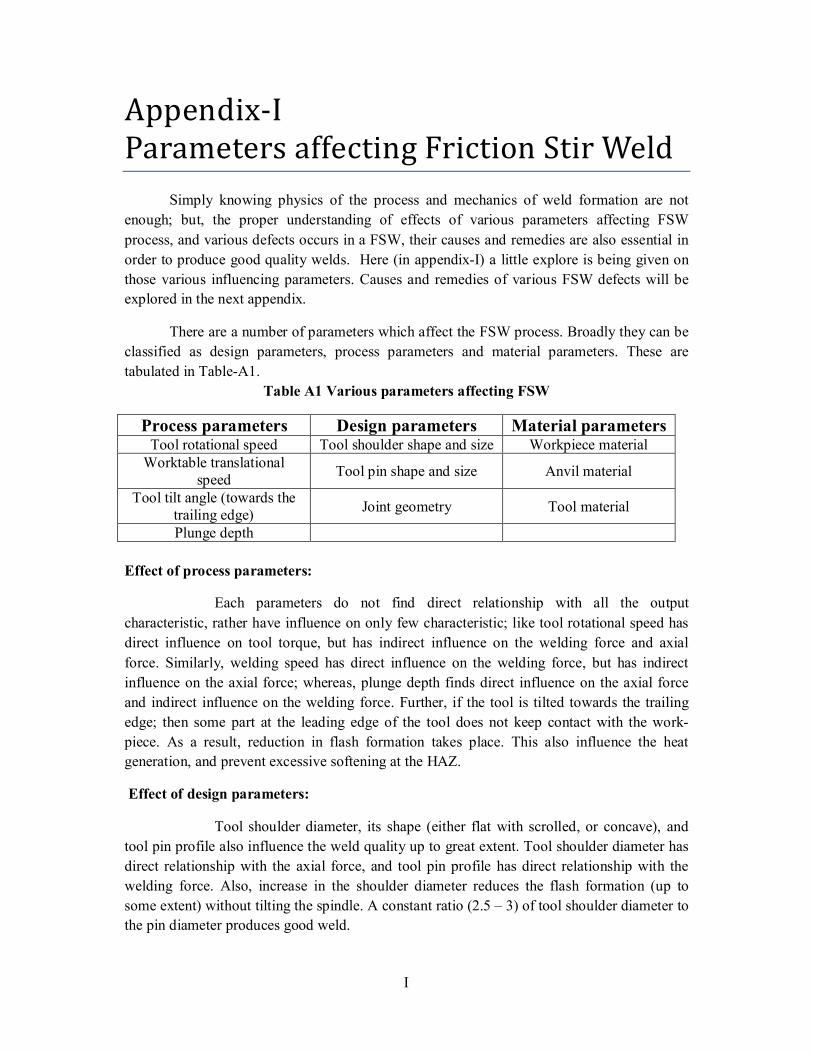
There are a number of parameters which affect the FSW process. Broadly they can be
classified as design parameters, process parameters and material parameters. These are
tabulated in Table-A1.
Table A1 Various parameters affecting FSW
Process parameters Design parameters Material parameters Tool rotational speed Tool shoulder shape and size Workpiece material
Worktable translational speed
Tool pin shape and size Anvil material
Tool tilt angle (towards the trailing edge)
Joint geometry Tool material
Plunge depth
Effect of process parameters:
Each parameters do not find direct relationship with all the output
characteristic, rather have influence on only few characteristic; like tool rotational speed has
direct influence on tool torque, but has indirect influence on the welding force and axial
force. Similarly, welding speed has direct influence on the welding force, but has indirect
influence on the axial force; whereas, plunge depth finds direct influence on the axial force
and indirect influence on the welding force. Further, if the tool is tilted towards the trailing
edge; then some part at the leading edge of the tool does not keep contact with the work-
piece. As a result, reduction in flash formation takes place. This also influence the heat
generation, and prevent excessive softening at the HAZ.
Effect of design parameters:
Tool shoulder diameter, its shape (either flat with scrolled, or concave), and
tool pin profile also influence the weld quality up to great extent. Tool shoulder diameter has
direct relationship with the axial force, and tool pin profile has direct relationship with the
welding force. Also, increase in the shoulder diameter reduces the flash formation (up to
some extent) without tilting the spindle. A constant ratio (2.5 – 3) of tool shoulder diameter to
the pin diameter produces good weld.

II
Effect of material parameters:
Tool material, anvil material and few other environmental conditions decide
the rate of heat dissipation. Use of a good heat conductive material for anvil, makes the
welding of some alloys (titanium and its alloys) easier; whereas for welding of aluminum and
copper alloys, use of low heat conductive materials for anvil reduces the unnecessary heat
loss during welding, and improves the weld quality.
III
Appendix-II Friction Stir Welding Defects
As it has been seen, that the whole FSW process is carried out by the machine itself
with least human intervention; so defect free weld is quite obvious. However, it has already
been mentioned in the previous section that distinct property of work-piece material and
wrongly chosen parameters can lead to defect formation. Hence, deciding suitable parameters
(e.g. designing of FSW tool shoulder and pin, selection of tool rpm, worktable feed and
plunge force etc.) for a particular work-piece material is a rigorous task. Proper
understanding of various FSW defects (their causes and remedies) can make this rigorous
task a little simpler. That`s why, here an attempt has been made to classify various FSW
defects, and then, on their causes and remedies.
There could be different perspective to classify various FSW defects. One perspective
could be based on the geometrical shape of the defect, like point, line or volume defect.
Another perspective could be based on the location of the defects; like surface defects, and
internal defects. Similarly one more perspective could be based on few certain conditions in
which few specific kinds of defects are formed; like defects from, either too cold weld
condition or too hot weld condition, and defects due to fault in designing of tool and/or
fixture etc. Here, the defects are being classified (Table-A2) considering the latter
perspective.
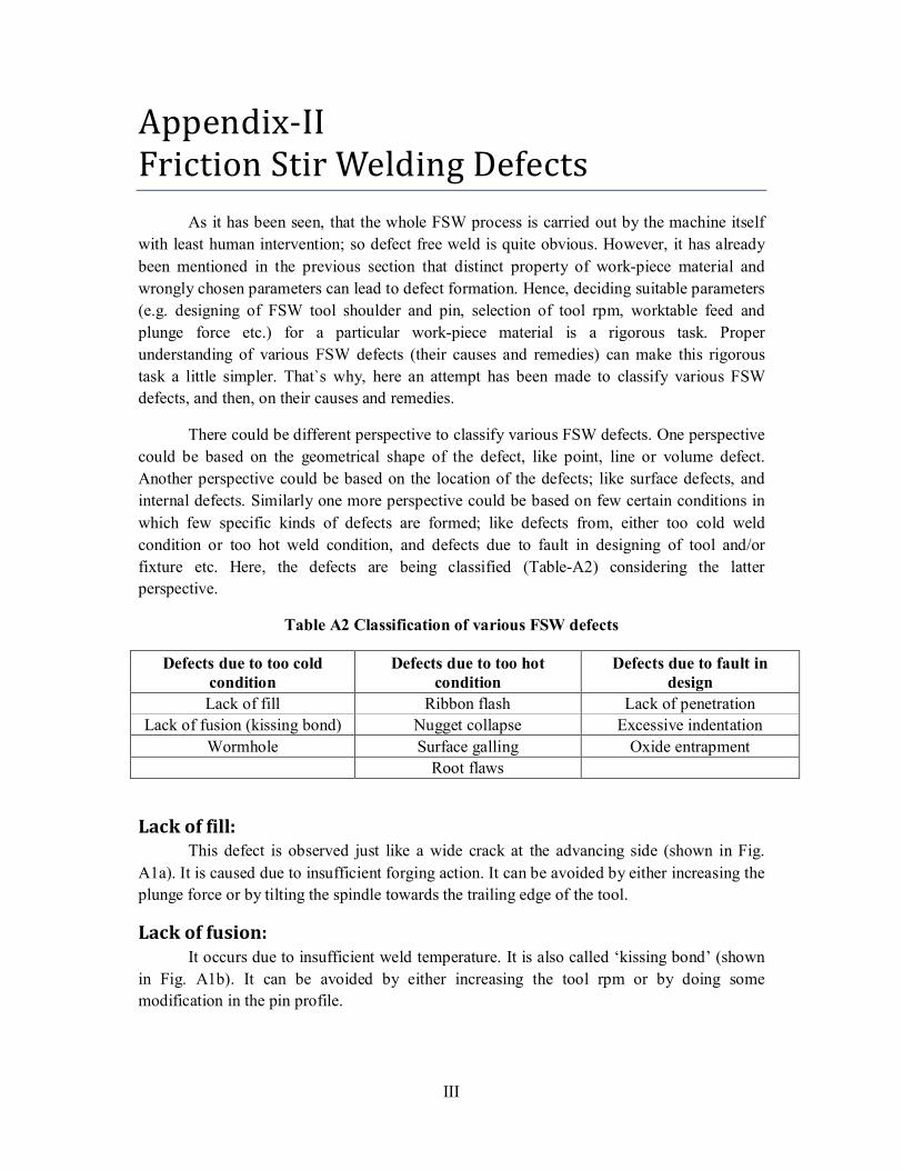
Table A2 Classification of various FSW defects
Defects due to too cold condition
Defects due to too hot condition
Defects due to fault in design
Lack of fill Ribbon flash Lack of penetration
Lack of fusion (kissing bond) Nugget collapse Excessive indentation
Wormhole Surface galling Oxide entrapment
Root flaws
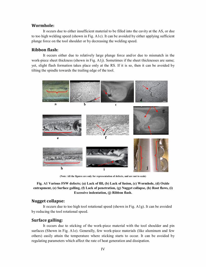
Lack of fill: This defect is observed just like a wide crack at the advancing side (shown in Fig.
A1a). It is caused due to insufficient forging action. It can be avoided by either increasing the
plunge force or by tilting the spindle towards the trailing edge of the tool.
Lack of fusion: It occurs due to insufficient weld temperature. It is also called ‘kissing bond’ (shown
in Fig. A1b). It can be avoided by either increasing the tool rpm or by doing some
modification in the pin profile.
IV
Wormhole: It occurs due to either insufficient material to be filled into the cavity at the AS, or due
to too high welding speed (shown in Fig. A1c). It can be avoided by either applying sufficient
plunge force on the tool shoulder or by decreasing the welding speed.
Ribbon flash: It occurs either due to relatively large plunge force and/or due to mismatch in the
work-piece sheet thickness (shown in Fig. A1j). Sometimes if the sheet thicknesses are same;
yet, slight flash formation takes place only at the RS. If it is so, then it can be avoided by
tilting the spindle towards the trailing edge of the tool.
(Note: All the figures are only for representation of defects, and are not to scale)
Fig. A1 Various FSW defects; (a) Lack of fill, (b) Lack of fusion, (c) Wormhole, (d) Oxide
entrapment, (e) Surface galling, (f) Lack of penetration, (g) Nugget collapse, (h) Root flaws, (i)
Excessive indentation, (j) Ribbon flash.
Nugget collapse: It occurs due to too high tool rotational speed (shown in Fig. A1g). It can be avoided
by reducing the tool rotational speed.
Surface galling: It occurs due to sticking of the work-piece material with the tool shoulder and pin
surfaces (Shown in Fig. A1e). Generally, few work-piece materials (like aluminum and few
others) easily attain the temperature where sticking starts to occur. It can be avoided by
regulating parameters which affect the rate of heat generation and dissipation.
V
Root flaws: It occurs due to sticking of the workpiece material on the backing plate or anvil
(shown in Fig A1h). This condition happens, when the pin height remains slightly larger than
the desired limit. It can be avoided by reducing the tool pin height to the desired limit.
Lack of penetration: It can be seen from Fig. A1f. It occurs due to slightly smaller pin length. It can be
avoided by increasing the tool pin length to the desired limit.
Excessive indentation: It is shown in Fig. A1i. Sometimes operator gives relatively larger plunge force in
order to avoid the defect occurs from lack of penetration, without increasing the pin length. It
results in excessive flash formation (also called excessive indentation). It can be avoided by
reducing the plunge force.
Oxide entrapment: This occurs due to presence of oxides on faying surfaces. Hence, when the sheets are
welded without removing the oxides; it got entrapped into the weld zone, and appears as a
zigzag line (shown in Fig. A1d), when micro-structural analysis is done. In order to prevent
this defect to occur, the oxides layers should be removed from the faying surfaces before
welding.
A mathematical model for defect free welds:
Fig. A2 (a) Creation of cavity due to pin travel (top view), (b) FSW tool subjected to
plunge force (side view)
��
�� AS
RS
P
δ
(a)
(b)
VI
As already mentioned that; when FSW tool is inserted into the workpiece, a pin hole
is formed, and when the tool starts to translate along the joining line the material stirring
around the pin hole (i.e. around the tool pin) is centrifugally forged into the cavity created
due to pin translation. So, the FSW process can be considered as the micro-hole formation
and filling process (as shown in the Fig. A2) [3].
Let us consider that;
�� =Welding speed
�� = Toolrotationalspeed
� = Weldingpressure
�= Weldingtoollinearmovement perrevolution
� = Workpiecesheetthickness
��������� = Radiusoftoolshoulder
���� = Radiusoftoolpin
����� = Weldingrate
����� = Inverseoftheweldingrate
� = Volumeofthemicroholecreatedduetopintravelperrevolution
� = Volumeofthematerialscentrifugallyforgedintotheholepersecond
� = Timethattheshoulderplayeffectonthemicrohole
Now, for a constant welding pressure P and constant tool rotation speed ��; the time for
which the shoulder play effect on the micro-hole would be,
� = ���������
��(1)
If the micro-hole gets completely filled, then the fill metal must be equal to the volume of the
micro-hole. If the time of filling of metal into the micro-hole is ��, then
� = ���
�� = �
� (2)
Obviously, the time for which the shoulder play effect on the micro-hole should be greater
than the time for filling the hole, in order to avoid any void or hole to remain present. Hence,
VII
� ≥ ��(3)
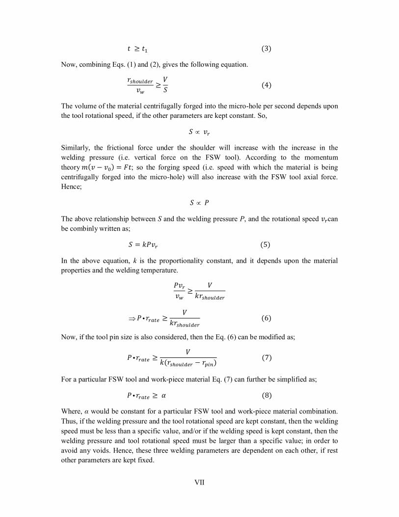
Now, combining Eqs. (1) and (2), gives the following equation.
���������
��≥
�
�(4)
The volume of the material centrifugally forged into the micro-hole per second depends upon
the tool rotational speed, if the other parameters are kept constant. So,
� ��
Similarly, the frictional force under the shoulder will increase with the increase in the
welding pressure (i.e. vertical force on the FSW tool). According to the momentum
theory�(� − ��) = ��; so the forging speed (i.e. speed with which the material is being
centrifugally forged into the micro-hole) will also increase with the FSW tool axial force.
Hence;
� �
The above relationship between S and the welding pressure P, and the rotational speed ��can
be combinly written as;
� = ����(5)
In the above equation, k is the proportionality constant, and it depends upon the material
properties and the welding temperature.
���
��≥
�
����������
� ����� ≥�
���������� (6)
Now, if the tool pin size is also considered, then the Eq. (6) can be modified as;
� ����� ≥�
�(��������� − ����) (7)
For a particular FSW tool and work-piece material Eq. (7) can further be simplified as;
� ����� ≥ �(8)
Where, α would be constant for a particular FSW tool and work-piece material combination.
Thus, if the welding pressure and the tool rotational speed are kept constant, then the welding
speed must be less than a specific value, and/or if the welding speed is kept constant, then the
welding pressure and tool rotational speed must be larger than a specific value; in order to
avoid any voids. Hence, these three welding parameters are dependent on each other, if rest
other parameters are kept fixed.