Embed Size (px)
Citation preview
Mercedes-Benz Engine Wiring 54.02Wiring Schematics
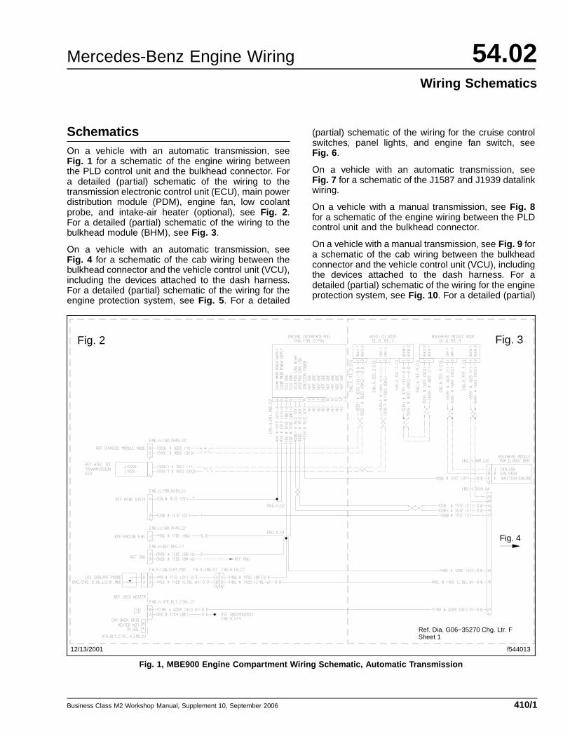
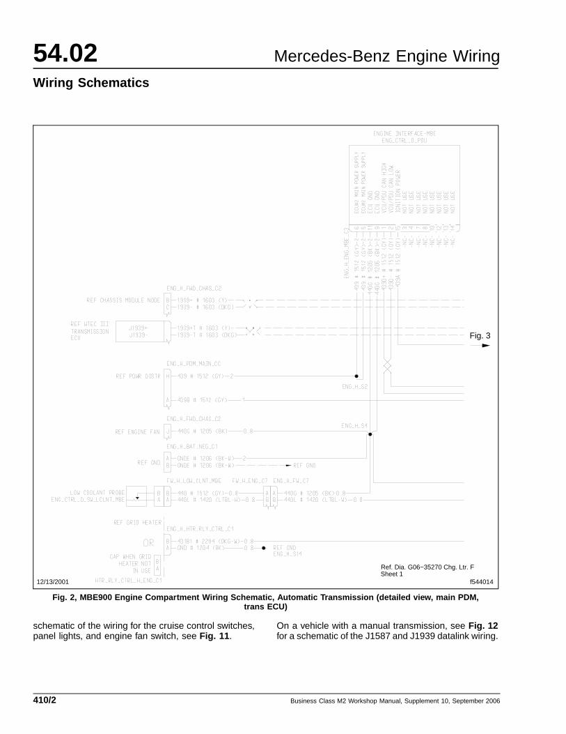
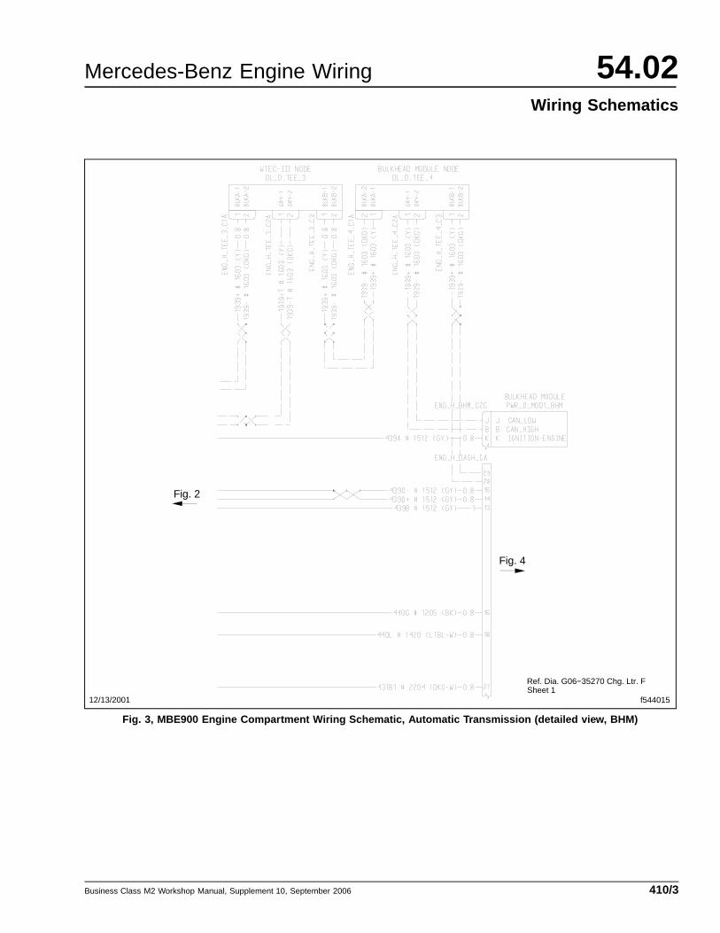
SchematicsOn a vehicle with an automatic transmission, seeFig. 1 for a schematic of the engine wiring betweenthe PLD control unit and the bulkhead connector. Fora detailed (partial) schematic of the wiring to thetransmission electronic control unit (ECU), main powerdistribution module (PDM), engine fan, low coolantprobe, and intake-air heater (optional), see Fig. 2 .For a detailed (partial) schematic of the wiring to thebulkhead module (BHM), see Fig. 3 .
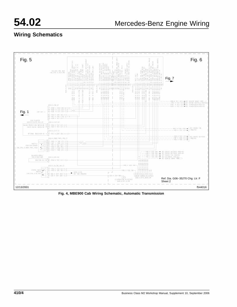
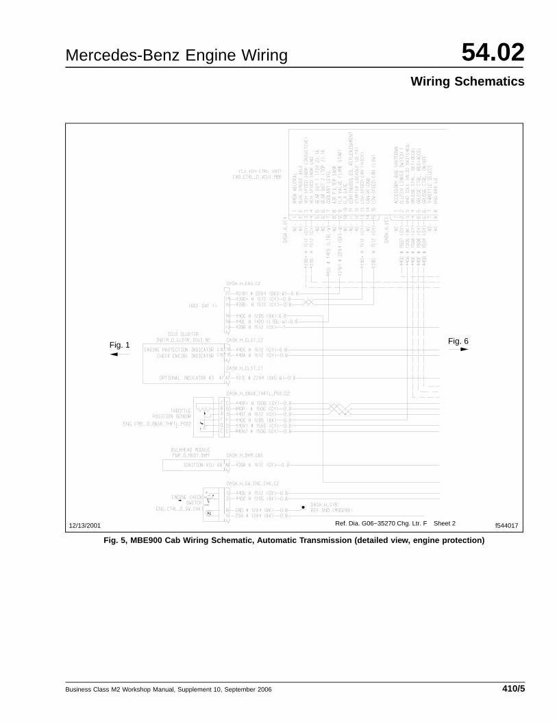
On a vehicle with an automatic transmission, seeFig. 4 for a schematic of the cab wiring between thebulkhead connector and the vehicle control unit (VCU),including the devices attached to the dash harness.For a detailed (partial) schematic of the wiring for theengine protection system, see Fig. 5 . For a detailed
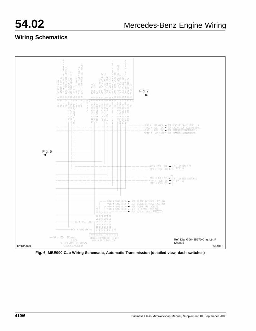
(partial) schematic of the wiring for the cruise controlswitches, panel lights, and engine fan switch, seeFig. 6 .
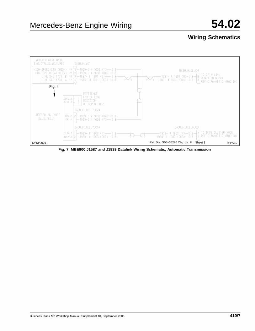
On a vehicle with an automatic transmission, seeFig. 7 for a schematic of the J1587 and J1939 datalinkwiring.
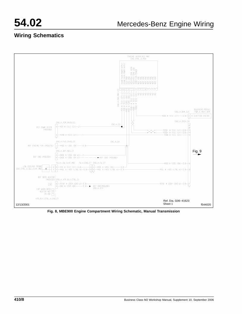
On a vehicle with a manual transmission, see Fig. 8for a schematic of the engine wiring between the PLDcontrol unit and the bulkhead connector.
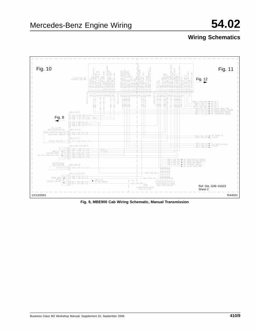
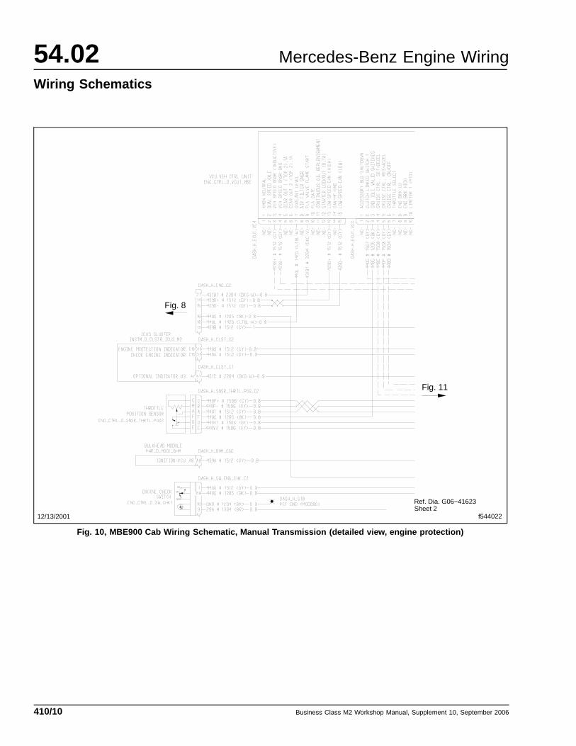
On a vehicle with a manual transmission, see Fig. 9 fora schematic of the cab wiring between the bulkheadconnector and the vehicle control unit (VCU), includingthe devices attached to the dash harness. For adetailed (partial) schematic of the wiring for the engineprotection system, see Fig. 10 . For a detailed (partial)
12/13/2001 f544013
Ref. Dia. G06−35270 Chg. Ltr. F
Fig. 2 Fig. 3
Fig. 4
Sheet 1
Fig. 1, MBE900 Engine Compartment Wiring Schematic, Automatic Transmission
Business Class M2 Workshop Manual, Supplement 10, September 2006 410/1
54.02 Mercedes-Benz Engine Wiring
Wiring Schematics
f544014
Ref. Dia. G06−35270 Chg. Ltr. F
Fig. 3
Sheet 112/13/2001
Fig. 2, MBE900 Engine Compartment Wiring Schematic, Automatic Transmission (detailed view, main PDM,trans ECU)
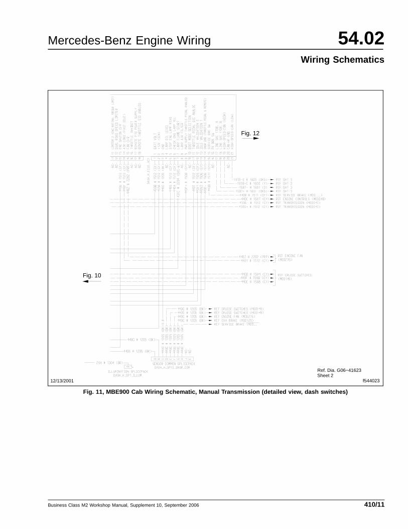
schematic of the wiring for the cruise control switches,panel lights, and engine fan switch, see Fig. 11 .
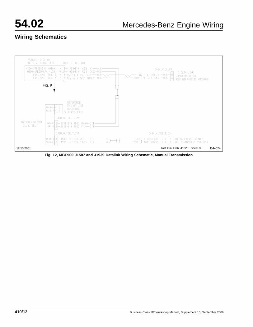
On a vehicle with a manual transmission, see Fig. 12for a schematic of the J1587 and J1939 datalink wiring.
Business Class M2 Workshop Manual, Supplement 10, September 2006410/2
Mercedes-Benz Engine Wiring 54.02Wiring Schematics
12/13/2001 f544015
Ref. Dia. G06−35270 Chg. Ltr. F
Fig. 4
Fig. 2
Sheet 1
Fig. 3, MBE900 Engine Compartment Wiring Schematic, Automatic Transmission (detailed view, BHM)
Business Class M2 Workshop Manual, Supplement 10, September 2006 410/3
54.02 Mercedes-Benz Engine Wiring
Wiring Schematics
12/13/2001 f544016
Ref. Dia. G06−35270 Chg. Ltr. F
Fig. 5 Fig. 6
Fig. 1
Sheet 2
Fig. 7
Fig. 4, MBE900 Cab Wiring Schematic, Automatic Transmission
Business Class M2 Workshop Manual, Supplement 10, September 2006410/4
Mercedes-Benz Engine Wiring 54.02Wiring Schematics
12/13/2001 f544017Ref. Dia. G06−35270 Chg. Ltr. F
Fig. 1 Fig. 6
Sheet 2
Fig. 5, MBE900 Cab Wiring Schematic, Automatic Transmission (detailed view, engine protection)
Business Class M2 Workshop Manual, Supplement 10, September 2006 410/5
54.02 Mercedes-Benz Engine Wiring
Wiring Schematics
12/13/2001 f544018
Ref. Dia. G06−35270 Chg. Ltr. F
Fig. 5
Fig. 7
Sheet 2
Fig. 6, MBE900 Cab Wiring Schematic, Automatic Transmission (detailed view, dash switches)
Business Class M2 Workshop Manual, Supplement 10, September 2006410/6
Mercedes-Benz Engine Wiring 54.02Wiring Schematics
12/13/2001 f544019Ref. Dia. G06−35270 Chg. Ltr. F
Fig. 4
Sheet 3
Fig. 7, MBE900 J1587 and J1939 Datalink Wiring Schematic, Automatic Transmission
Business Class M2 Workshop Manual, Supplement 10, September 2006 410/7
54.02 Mercedes-Benz Engine Wiring
Wiring Schematics
12/13/2001 f544020
Fig. 9
Ref. Dia. G06−41623Sheet 1
Fig. 8, MBE900 Engine Compartment Wiring Schematic, Manual Transmission
Business Class M2 Workshop Manual, Supplement 10, September 2006410/8
Mercedes-Benz Engine Wiring 54.02Wiring Schematics
12/13/2001 f544021
Ref. Dia. G06−41623
Fig. 10 Fig. 11
Fig. 8
Fig. 12
Sheet 2
Fig. 9, MBE900 Cab Wiring Schematic, Manual Transmission
Business Class M2 Workshop Manual, Supplement 10, September 2006 410/9
54.02 Mercedes-Benz Engine Wiring
Wiring Schematics
12/13/2001 f544022
Ref. Dia. G06−41623
Fig. 8
Fig. 11
Sheet 2
Fig. 10, MBE900 Cab Wiring Schematic, Manual Transmission (detailed view, engine protection)
Business Class M2 Workshop Manual, Supplement 10, September 2006410/10
Mercedes-Benz Engine Wiring 54.02Wiring Schematics
12/13/2001 f544023
Ref. Dia. G06−41623
Fig. 12
Fig. 10
Sheet 2
Fig. 11, MBE900 Cab Wiring Schematic, Manual Transmission (detailed view, dash switches)
Business Class M2 Workshop Manual, Supplement 10, September 2006 410/11
54.02 Mercedes-Benz Engine Wiring
Wiring Schematics
12/13/2001 f544024Ref. Dia. G06−41623
Fig. 9
Sheet 3
Fig. 12, MBE900 J1587 and J1939 Datalink Wiring Schematic, Manual Transmission
Business Class M2 Workshop Manual, Supplement 10, September 2006410/12