Embed Size (px)
Citation preview
Troubleshoot The AC CircuitryTroubleshoot The AC Circuitry15-60KW TQG Generator:15-60KW TQG Generator:
* AC Circuits- Schematics- Wiring Diagram
*Component Identification and function.
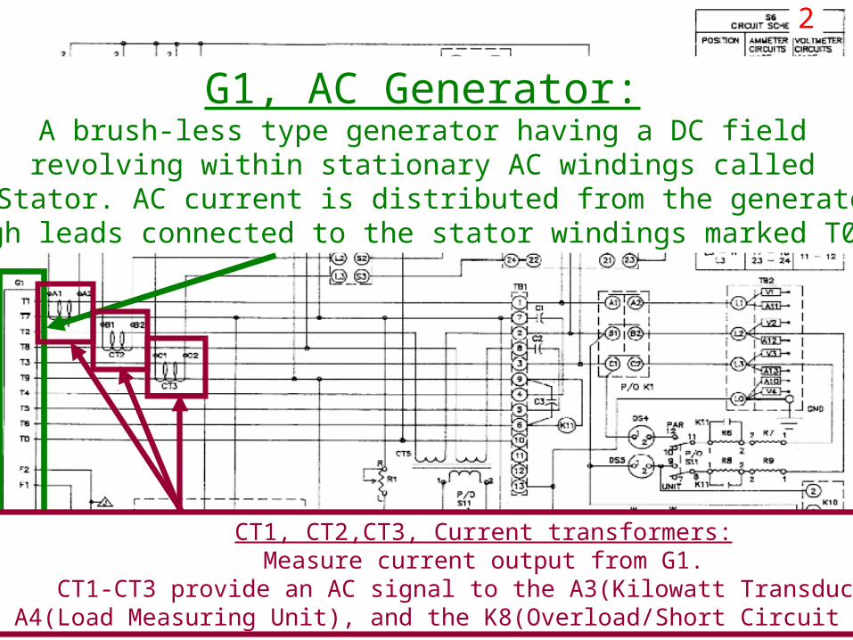
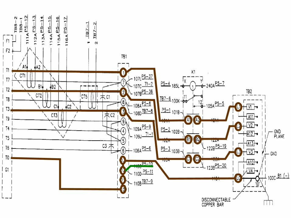
G1, AC Generator:A brush-less type generator having a DC field
revolving within stationary AC windings calleda Stator. AC current is distributed from the generator
through leads connected to the stator windings marked T0-T12.
CT1, CT2,CT3, Current transformers:Measure current output from G1.
CT1-CT3 provide an AC signal to the A3(Kilowatt Transducer), A4(Load Measuring Unit), and the K8(Overload/Short Circuit Relays).
2

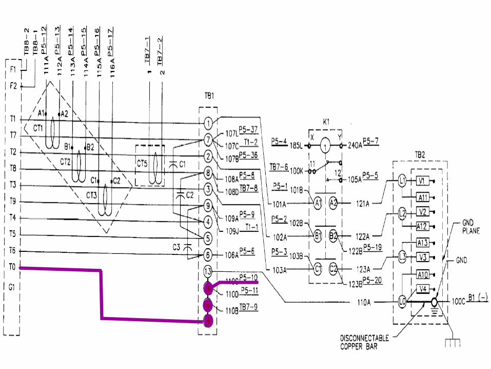
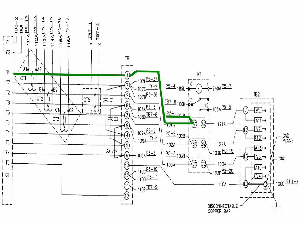
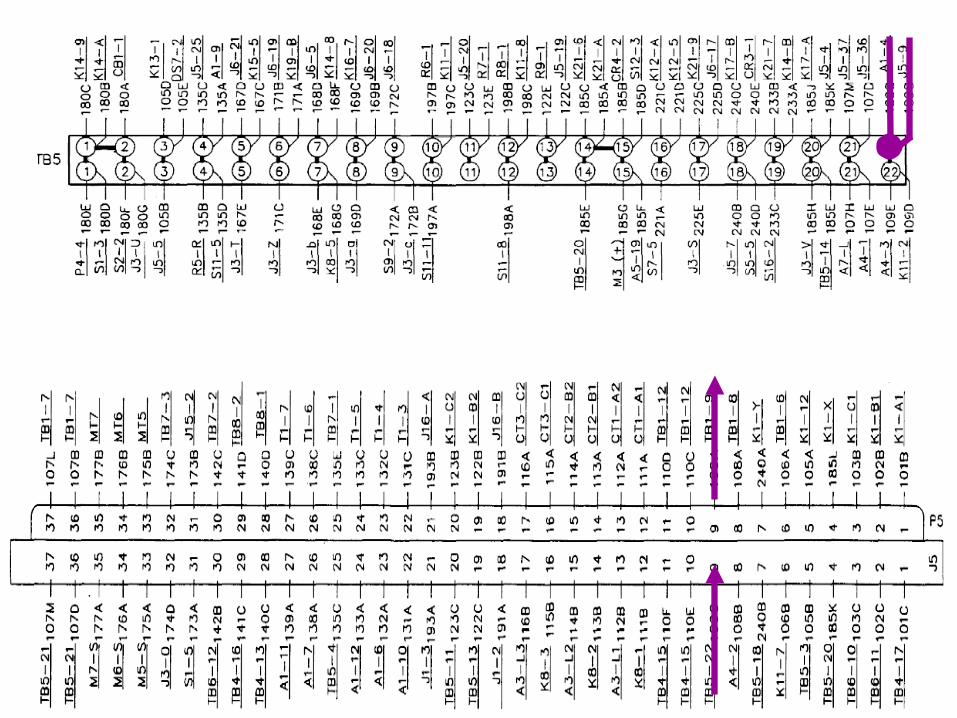
DC Schematic K1, AC Circuit Interrupter:When energized by the S5, it’s contacts, seen below, will and close
and allow current from the G1(Main Generator), toFlow to TB2(Load Terminal Board).
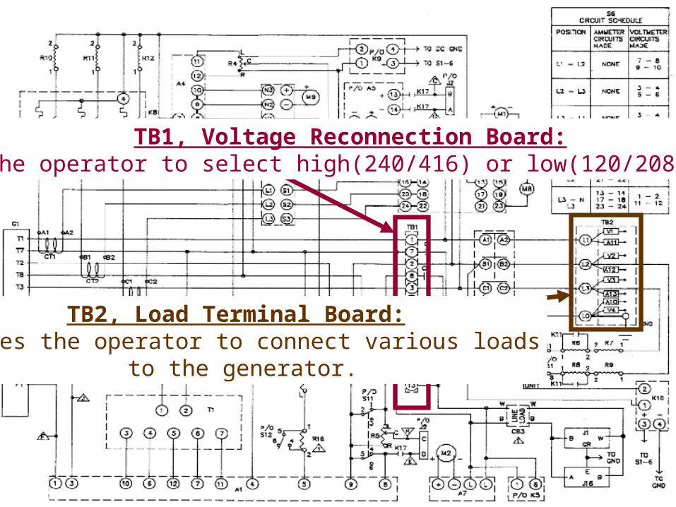
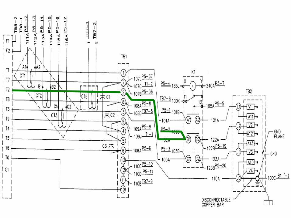
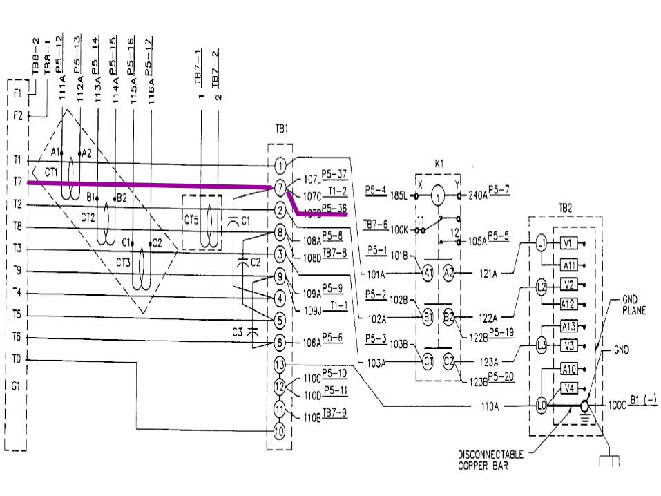
TB1, Voltage Reconnection Board:Enables the operator to select high(240/416) or low(120/208) voltages.
TB2, Load Terminal Board:Enables the operator to connect various loads
to the generator.
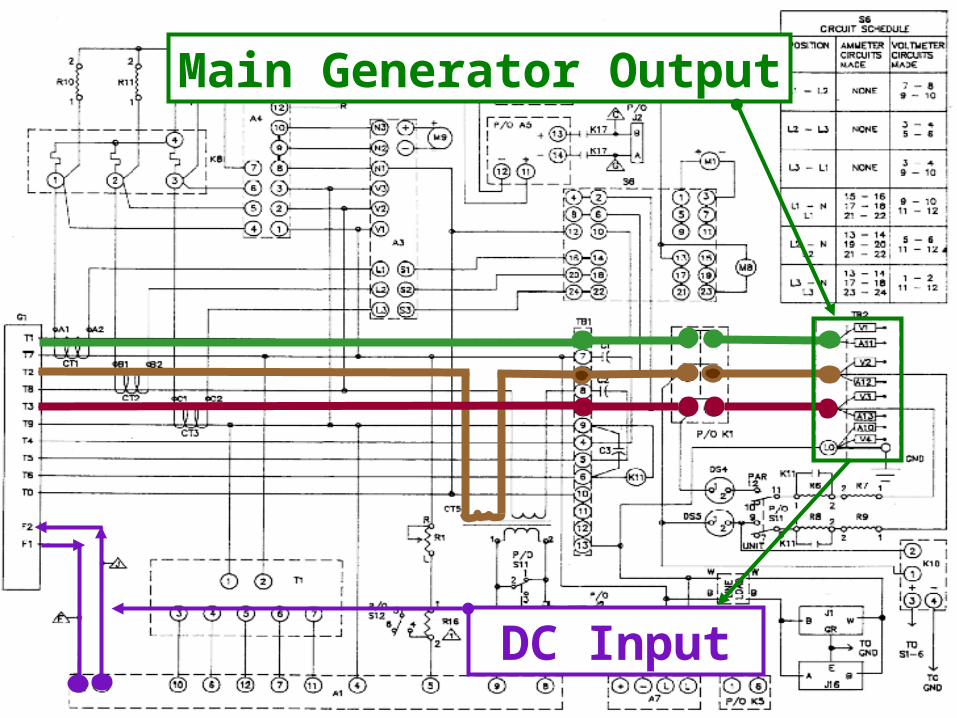
Main Generator Output
DC Input
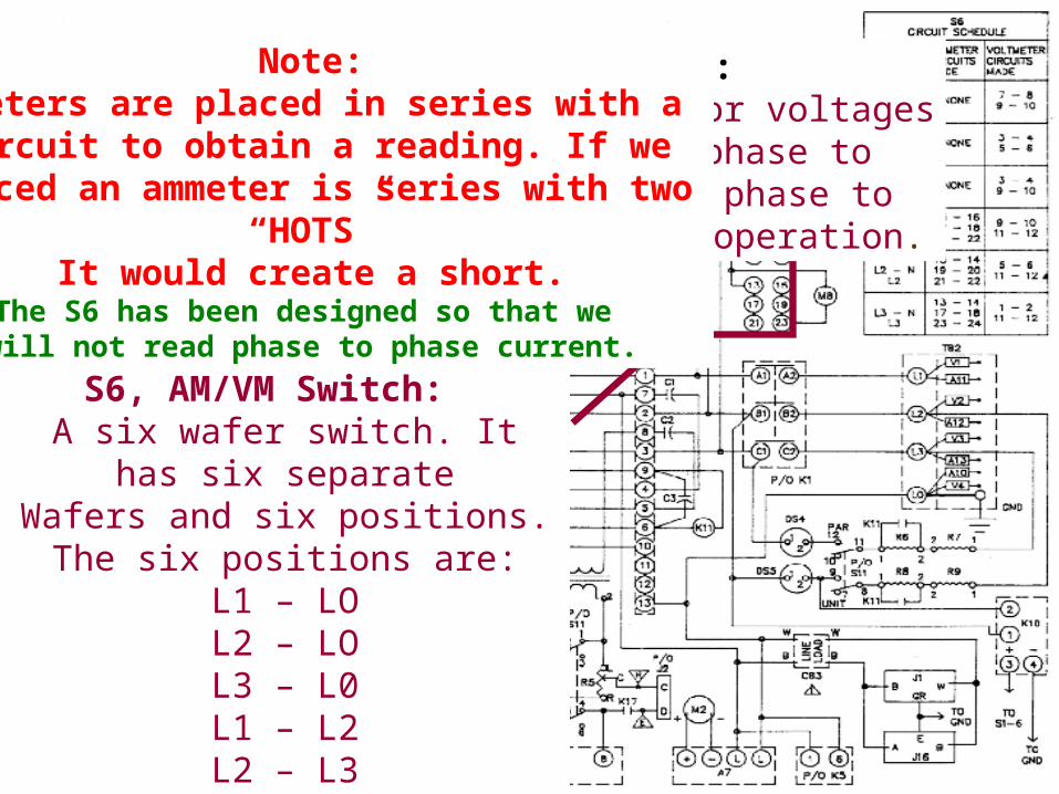
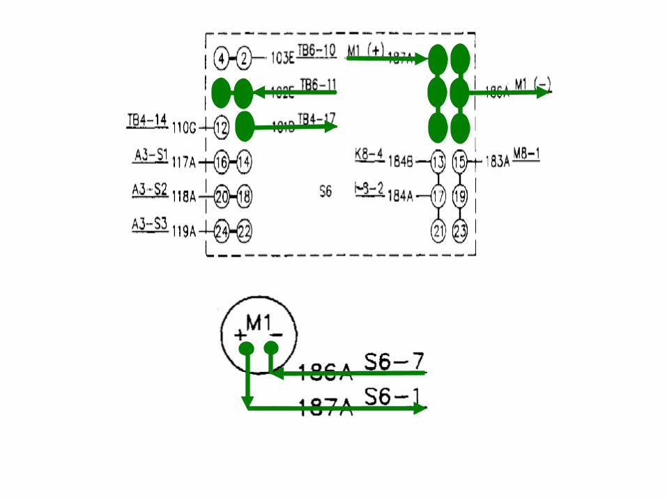
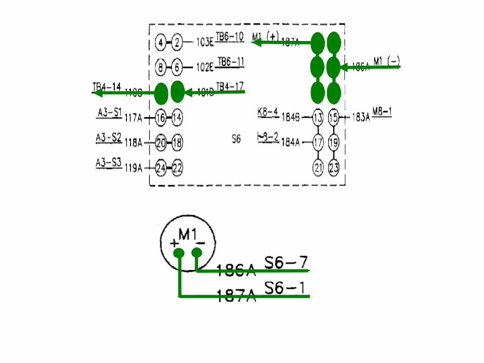
S6, AM/VM Transmitter: Allows the operator to monitor voltages
of any phase to phase or phase to neutral and current of any phase to neutral while the set is in operation.
S6, AM/VM Switch: A six wafer switch. It has six separate
Wafers and six positions.The six positions are:
L1 – LOL2 – LOL3 – L0L1 – L2L2 – L3L1 – L3
Note:Ammeters are placed in series with a
circuit to obtain a reading. If weplaced an ammeter is series with two
“HOTS”It would create a short.
The S6 has been designed so that we will not read phase to phase current.
M1, AC Volt Meter:Indicates AC Voltage output
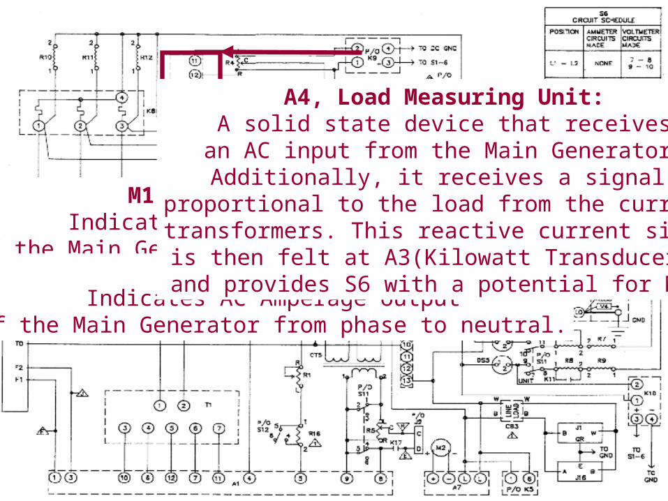
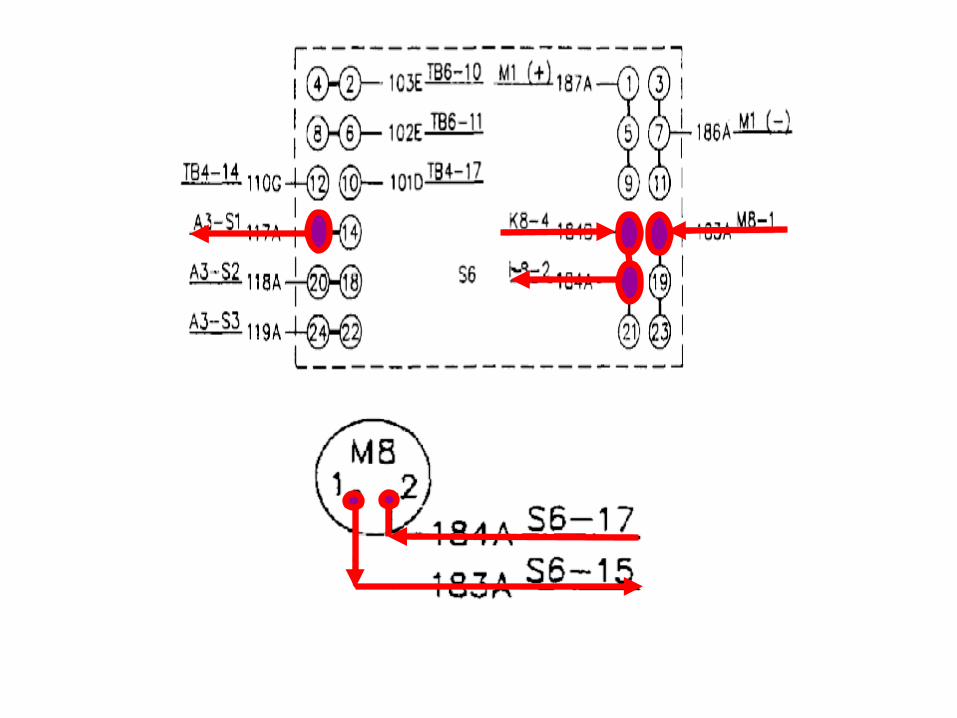
of the Main Generator from phase to phaseor phase to neutral.M8, AC Ammeter:
Indicates AC Amperage outputof the Main Generator from phase to neutral.
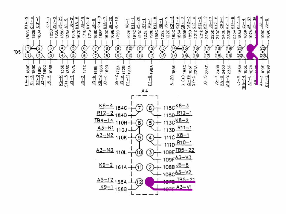
A4, Load Measuring Unit:A solid state device that receives
an AC input from the Main Generator.Additionally, it receives a signal
proportional to the load from the current transformers. This reactive current signalis then felt at A3(Kilowatt Transducer), and provides S6 with a potential for M8.
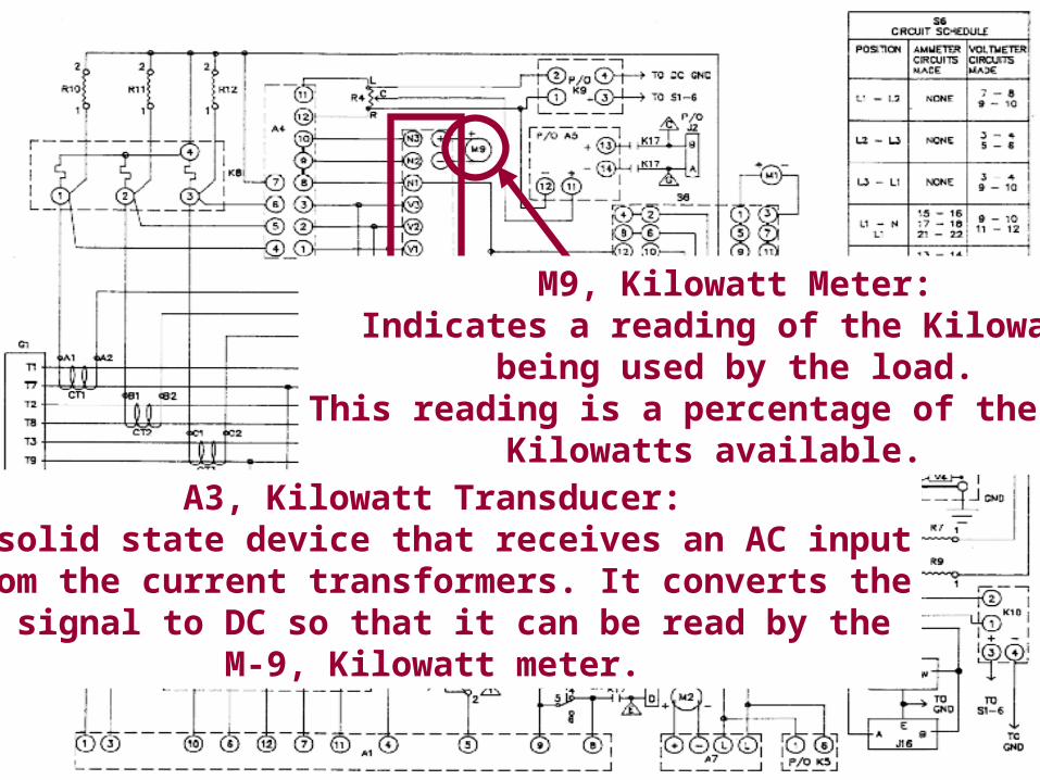
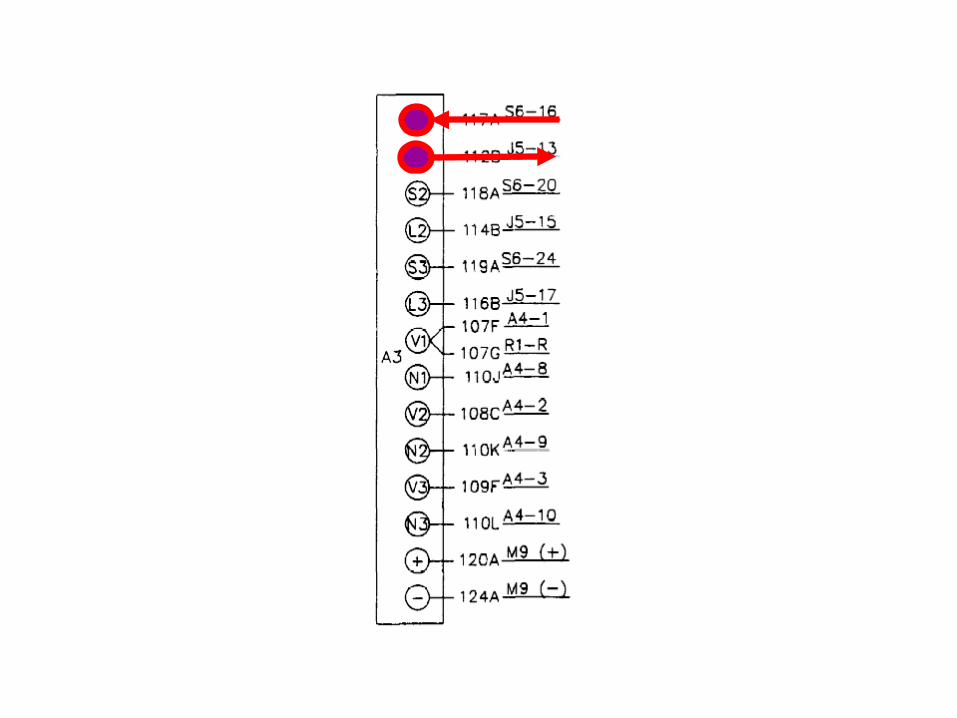
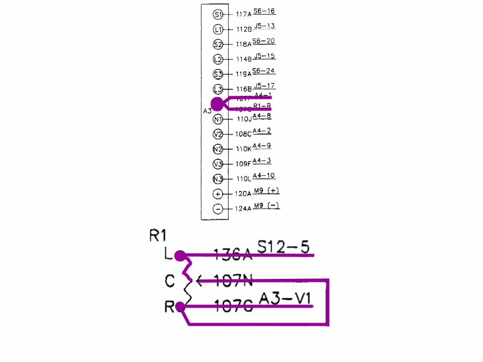
A3, Kilowatt Transducer:A solid state device that receives an AC inputfrom the current transformers. It converts theAC signal to DC so that it can be read by the
M-9, Kilowatt meter.
M9, Kilowatt Meter:Indicates a reading of the Kilowatts
being used by the load.This reading is a percentage of the total
Kilowatts available.
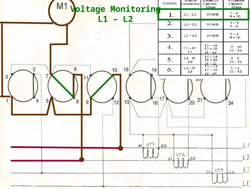
Voltage MonitoringL1 – L2
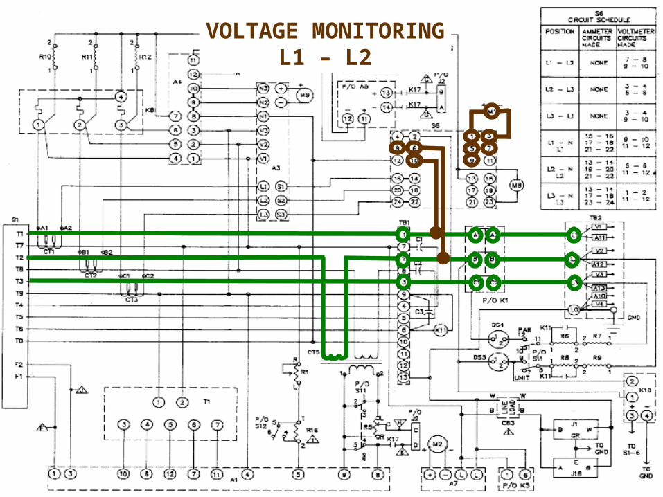
VOLTAGE MONITORINGL1 – L2
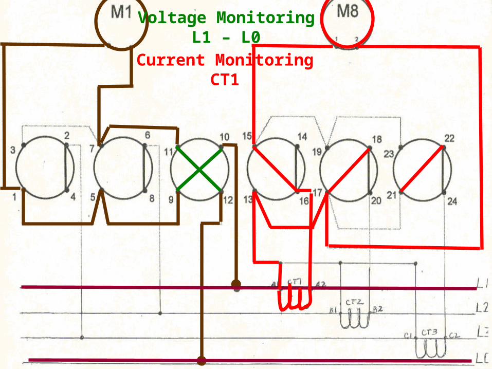
Voltage MonitoringL1 – L0
Current MonitoringCT1
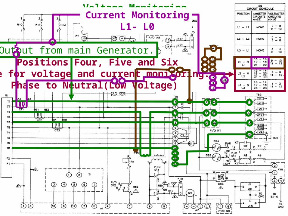
Positions Four, Five and Sixare for voltage and current monitoring.
Phase to Neutral(Low Voltage)
AC Output from main Generator.
Voltage MonitoringL1- L0Current MonitoringL1- L0
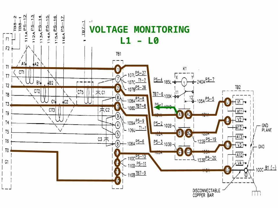
VOLTAGE MONITORINGL1 – L0
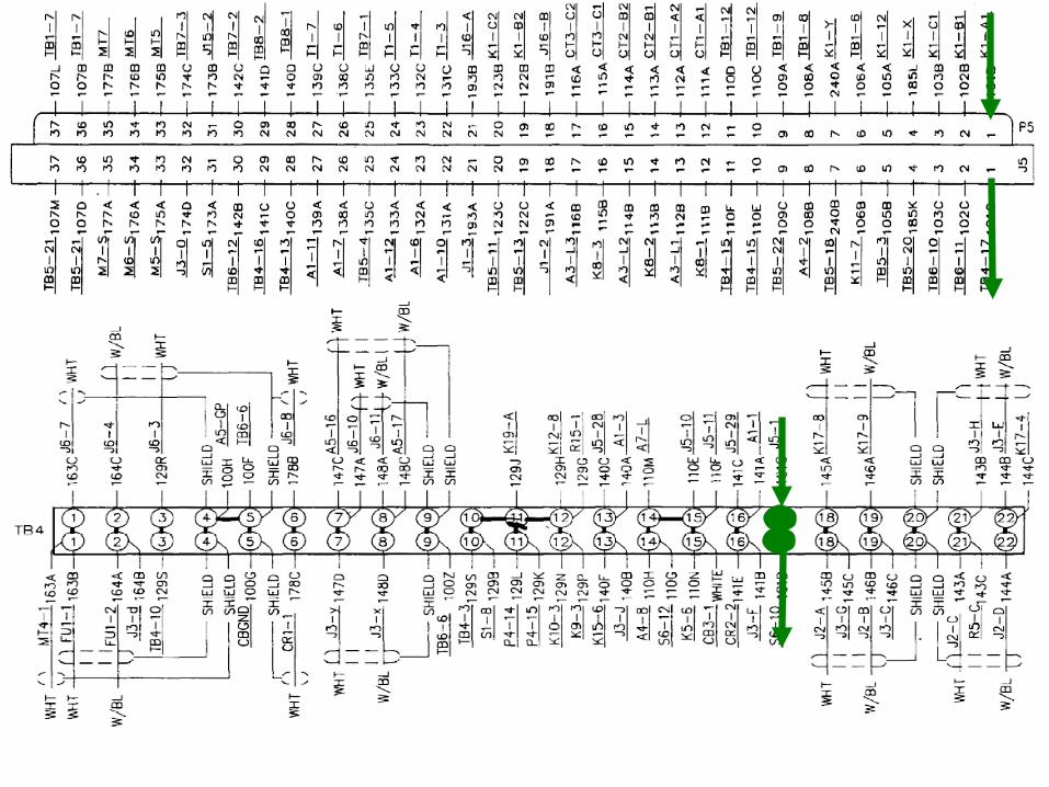
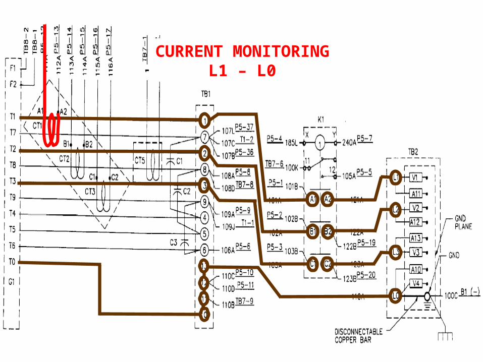
CURRENT MONITORINGL1 – L0
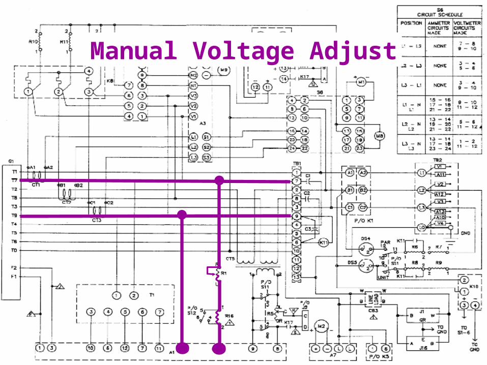
Manual Voltage Adjust.Manual Voltage Adjust.
By increasing or decreasingBy increasing or decreasingthe amount of DC currentthe amount of DC current
across the exciter field coil,across the exciter field coil,we can increase or decreasewe can increase or decrease
the output voltage of the the output voltage of the generator .generator .
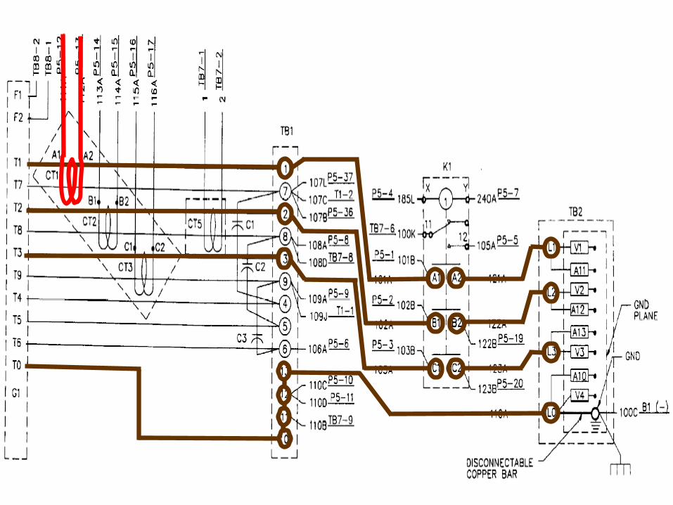
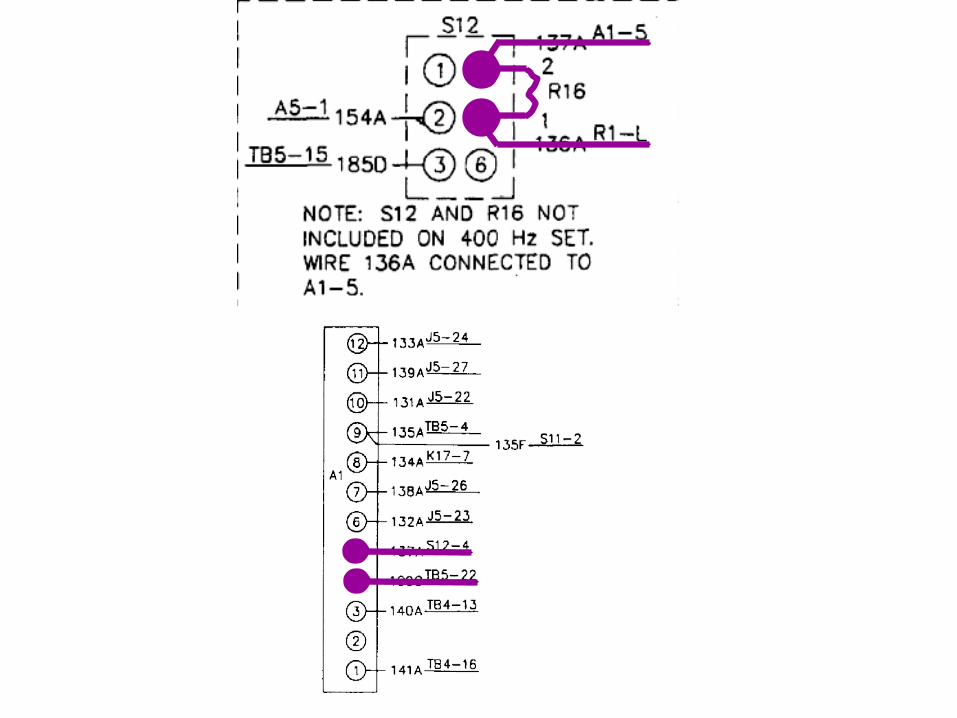
A1, AC Voltage Regulator:A solid state device that receives an input from T1(Potential Transformer),
CT5(Droop Current Transformer) and T7(Generator Phase Winding),that is directly proportional to the load current.
It then sends an output signal to F1 & F2(Exciter Stator).
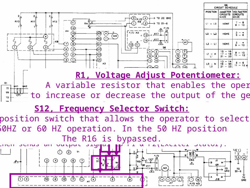
R1, Voltage Adjust Potentiometer:A variable resistor that enables the operator
to increase or decrease the output of the generatorfrom the control panel.
R16, Voltage Adjust Resistor:Provides the S12 with a predetermined amount of resistance
when the generator is operating in a 50 HZ mode.
S12, Frequency Selector Switch:A two position switch that allows the operator to select
50HZ or 60 HZ operation. In the 50 HZ positionThe R16 is bypassed.
Manual Voltage Adjust
Frequency Monitoring.Frequency Monitoring.
Allows the Operator to Allows the Operator to monitor the generator setmonitor the generator set
frequency.frequency.
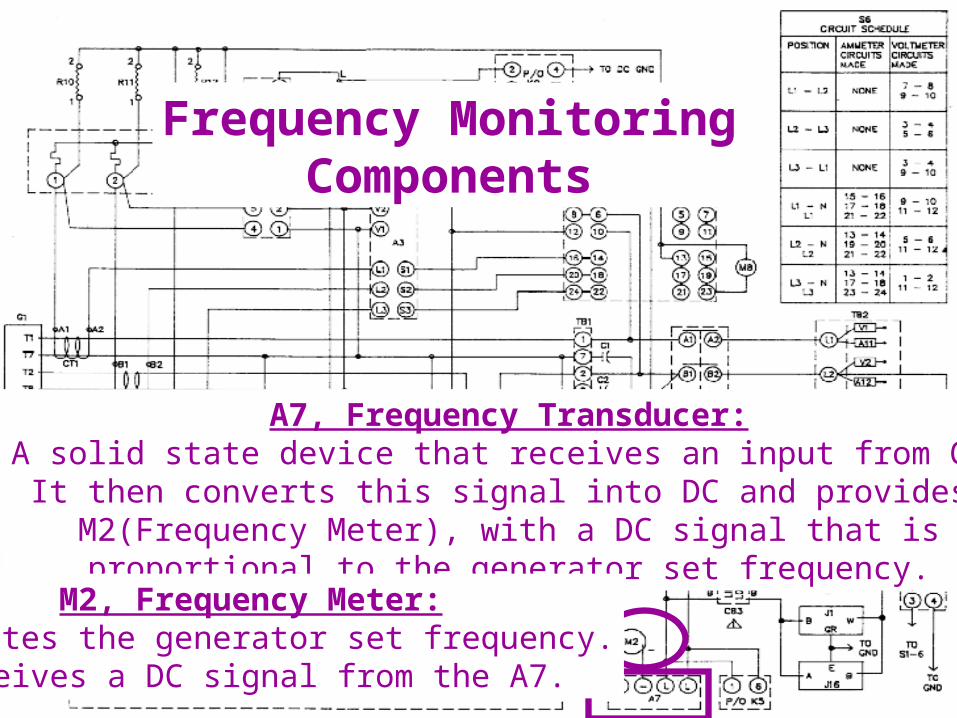
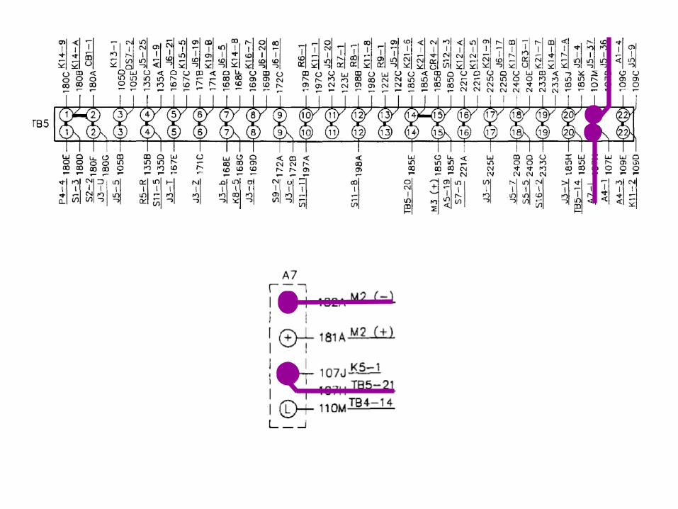
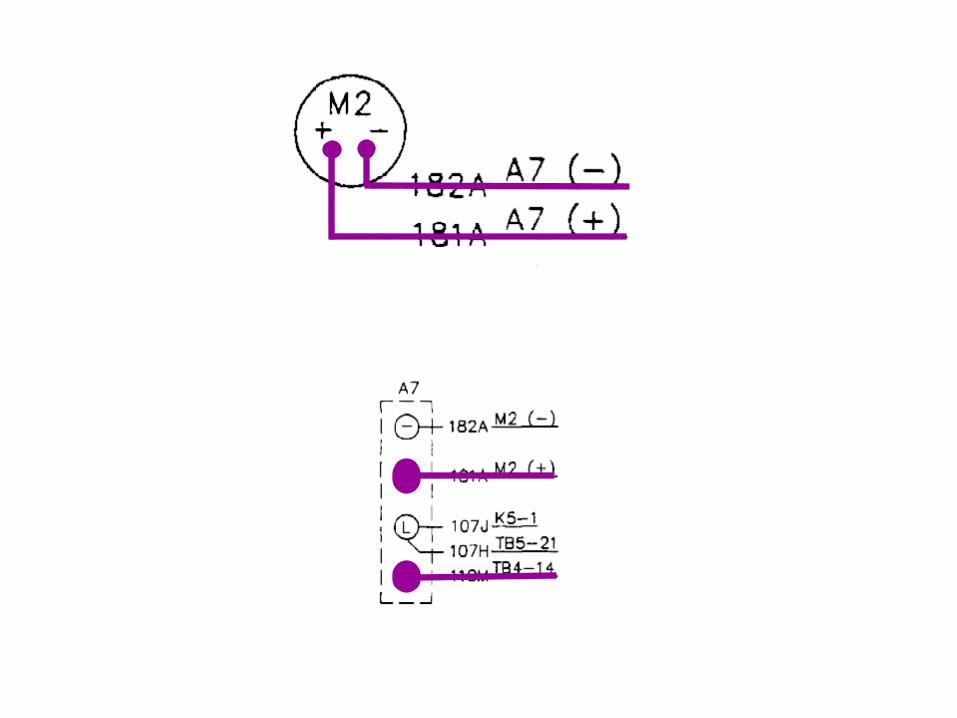
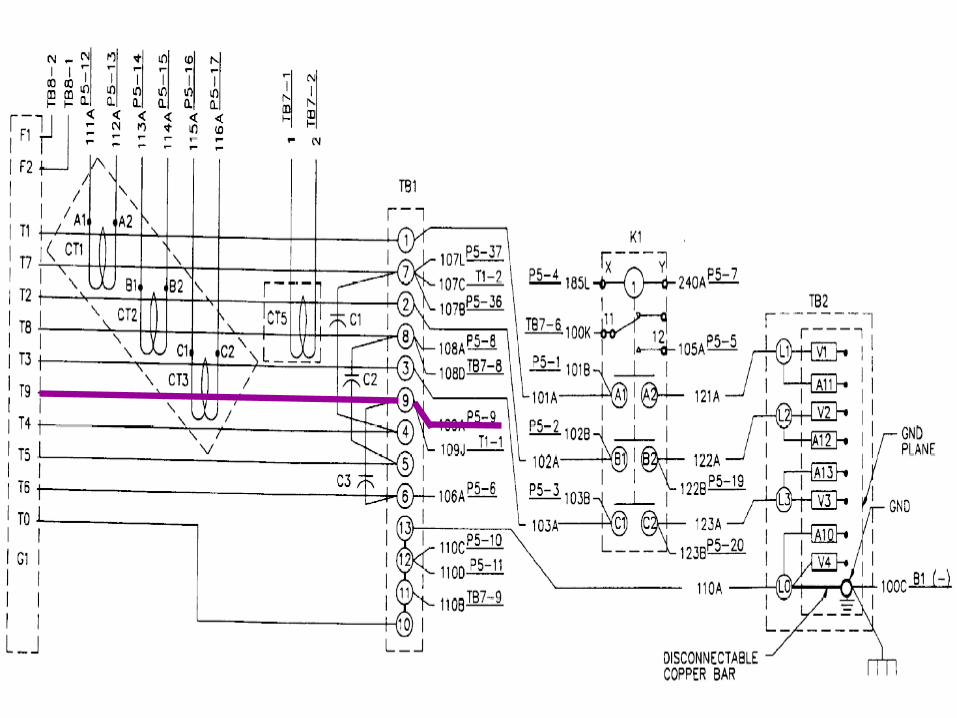
A7, Frequency Transducer:A solid state device that receives an input from G1.It then converts this signal into DC and provides M2(Frequency Meter), with a DC signal that is
proportional to the generator set frequency.M2, Frequency Meter:
Indicates the generator set frequency.Receives a DC signal from the A7.
Frequency MonitoringComponents
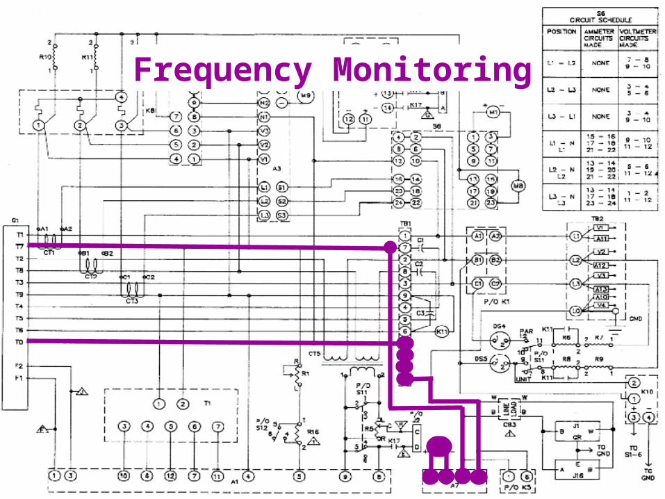
Frequency Monitoring