Embed Size (px)
Citation preview
Lesson
Preparing and Using Schematics for Wiring
Applications Using Cable
Interest Approach
You are going to wire a new room you are building onto your home.
The room will be on its own circuit.
In the room, you will want a light in the ceiling controlled by a switch and four duplex receptacles.
Interest Approach
The receptacles should be wired so that the top receptacle on each is always “hot”. The bottom receptacle should be controlled by an additional switch that is to be mounted next to the switch controlling the ceiling light. The power will come into the room through the box where the switches are located.
Interest Approach
How would you go about wiring the room? Would you use 2-wire or 3-wire cable and where?Which wires will be connected to which terminals?What materials are needed?

Interest Approach
If you were going on a trip, how would you choose the right roads to take you to your desired destination?
Interest Approach
Wiring is much the same way. In order to wire correctly and in the most efficient manner, We need some sort of “road map” to get us there. The diagrams you will construct will serve as a “road map” so you can wire an exercise correctly and most efficiently from the very beginning
Student Learning Objectives
Identify and draw various symbols used in drawing wiring diagrams or schematics.
Describe rules to follow in diagramming various circuits.
Student Learning Objectives
Draw and explain diagrams of circuits using keyless lampholders, pull-chain lampholders, duplex receptacles, and single-pole switches.
Draw and explain diagrams of circuits using lampholders with 3-way and 4-way switches.
Student Learning Objectives
Draw and explain diagrams of circuits using a combination single-pole switch and receptacle with a lampholder and applications where receptacles are split for switching.
Terms
3-way switches
4-way switches
Combination single-pole switch and receptacle
Control or common terminal
Duplex receptacle
Keyless lampholder
Pull-chain lampholder
Switch loop connection
Traveler terminal
Objective 1
Identify and draw various symbols used in drawing
wiring diagrams or schematics.
What symbols are used for various electrical devices and how are they drawn?
In order to successfully draw a wiring circuit on paper, one needs to use various symbols that represent the equipment and techniques that will need to be followed in wiring.
The following are symbols that will be used in this lesson.
It is important to note that other resources may use different symbols.
The exact symbol itself is not as important as how to construct diagrams that will allow the wiring activity to be accomplished correctly.
Cable Types
In cable, there are four different colors or kinds of wire that one will use depending on the type of wire that is being used.
Using 12-gauge wire as the example, there are four types of cable that one may buy.
Cable Types
One is 12/2 with ground, which has one black conductor, one white conductor, and a bare ground conductor.
Cable Types
A second cable is 12/2 without ground, which is the same as 12/2 with ground except that no bare ground conductor exists.
Cable Types
A third type of cable is 12/3 with ground, which has one black conductor, one white conductor, one red conductor, and one bare ground conductor.
Cable Types
The last type is 12/3 without ground which is like the 12/2 without ground. It has the three colored conductors, but no bare conductor.
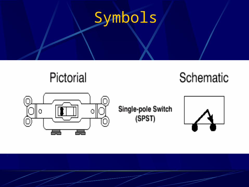
Symbols
The symbols used for conductors and their respective colors are:
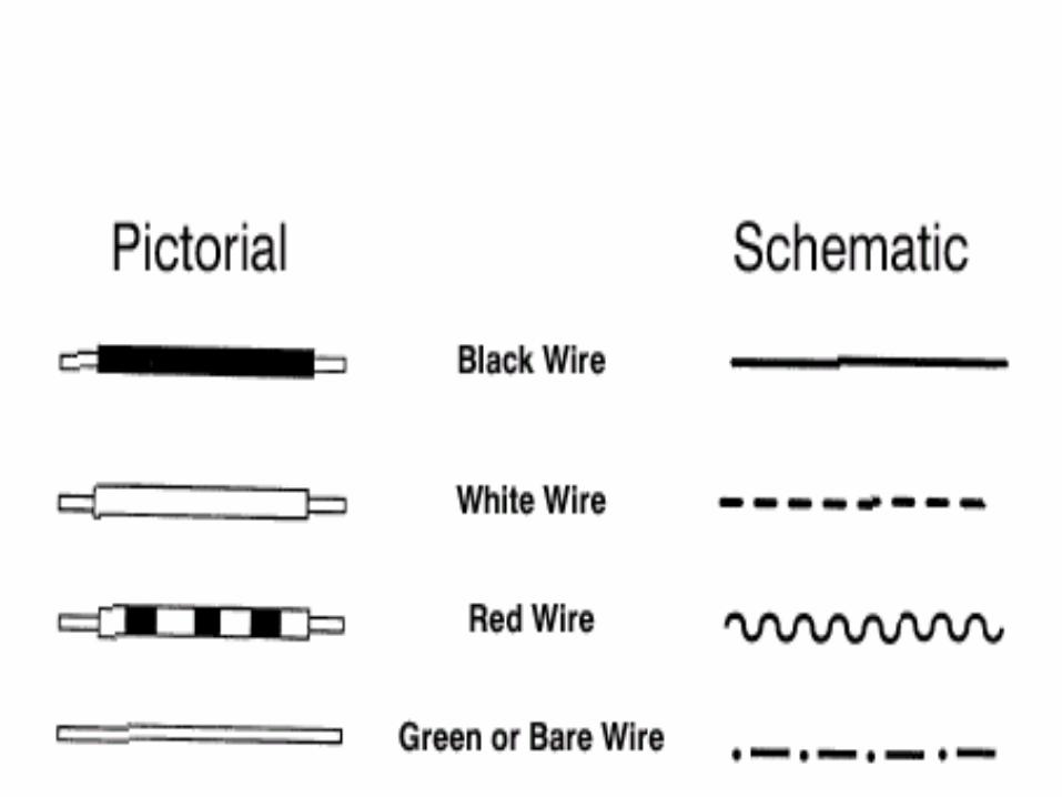
Symbols
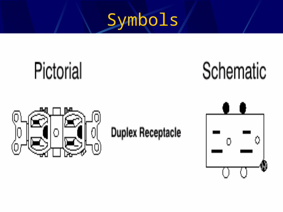
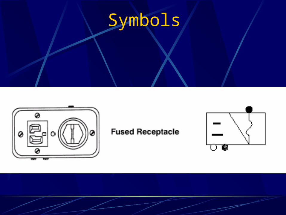
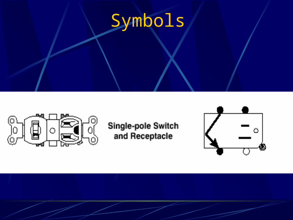
Various devices are used as lampholders, switches, and receptacles.
Symbols
Symbols
Symbols
Symbols
Symbols
Symbols
Symbols
Symbols
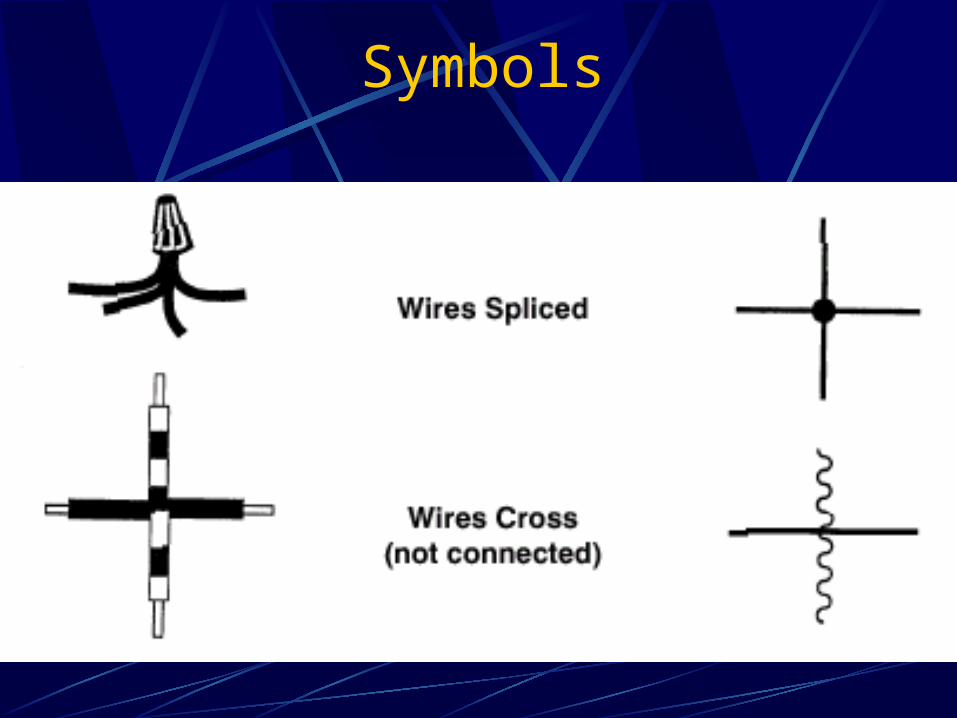
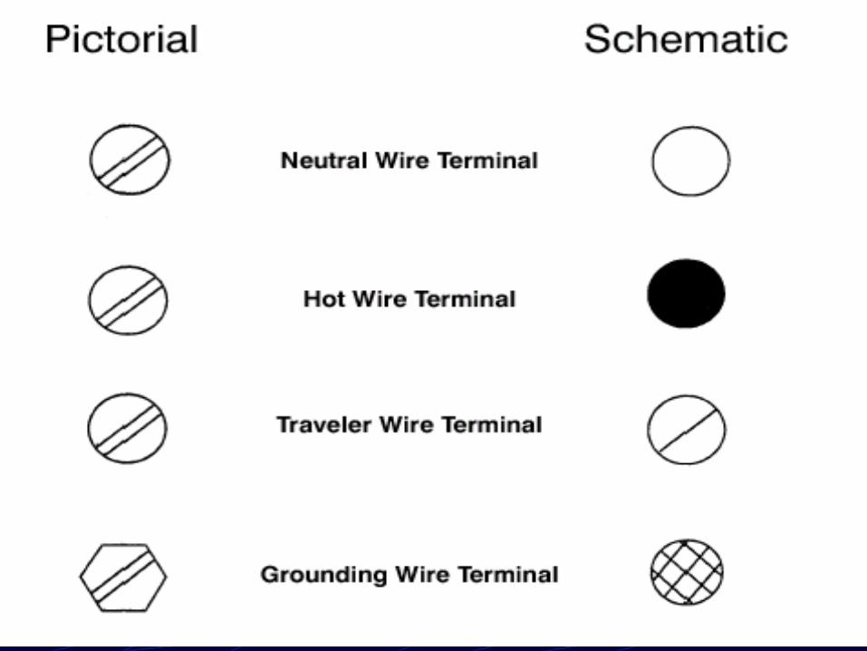
Additional symbols are used to identify terminals and
indicate if wires are spliced or just crossing over.
Symbols
Symbols
Objective 2
Describe rules to follow in diagramming various
circuits.
What rules should be followed in diagramming
various circuits?
Diagramming
In order to successfully diagram circuits there are a few rules and order to follow in the diagramming process that will be helpful.
Diagramming
Again, there are probably many different techniques to diagramming a circuit.
The following represents one.
Diagramming
Generally, black and red conductors carry “hot” power or current from the source(SEP) to the devices within the circuit.
Diagramming
The white conductor is always used to carry the current back to the source.
This conductor is often referred to as the neutral conductor.
Diagramming
There may be some applications that would require a white conductor to actually carry “hot” current.
This is referred to as a switch loop connection and will be discussed later.
Diagramming
When completing the diagram, it may be helpful to draw the white, neutral conductor from the source to its final destination within the circuit, first.Duplex receptacles and pull-chain lampholders are normally wired so that they have “hot” or unswitched power at all times.
Diagramming
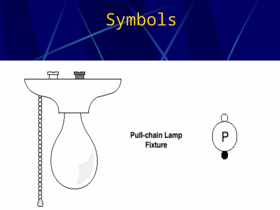
Pull-chain lampholders have a switch built into the device.
The lampholder is turned on and off by pulling the string or chain connected to the lampholder.
Diagramming
Duplex receptacles are a device that will receive two plugs.
In the case where you want half of a duplex receptacle controlled by a switch, you would not wire the entire receptacle hot.
Diagramming
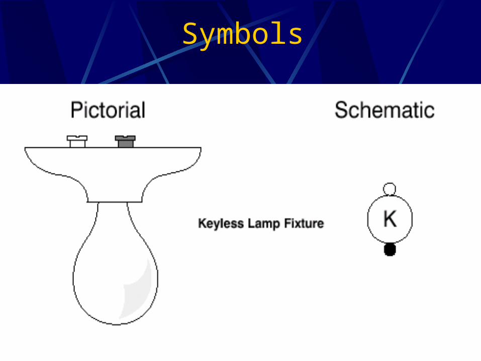
Keyless lampholders are an example of a device that must have a switch to turn the power “on” or “off”.
Switching is always done in the ungrounded or “hot” conductor.
Diagramming
On occasion it may be more convenient to bring the source into the lampholder first and then go to the switch.
This is called a switch loop.
Diagramming
In a switch loop connection using two-wire cable, it is necessary to use the white wire as the hot line to the switch.
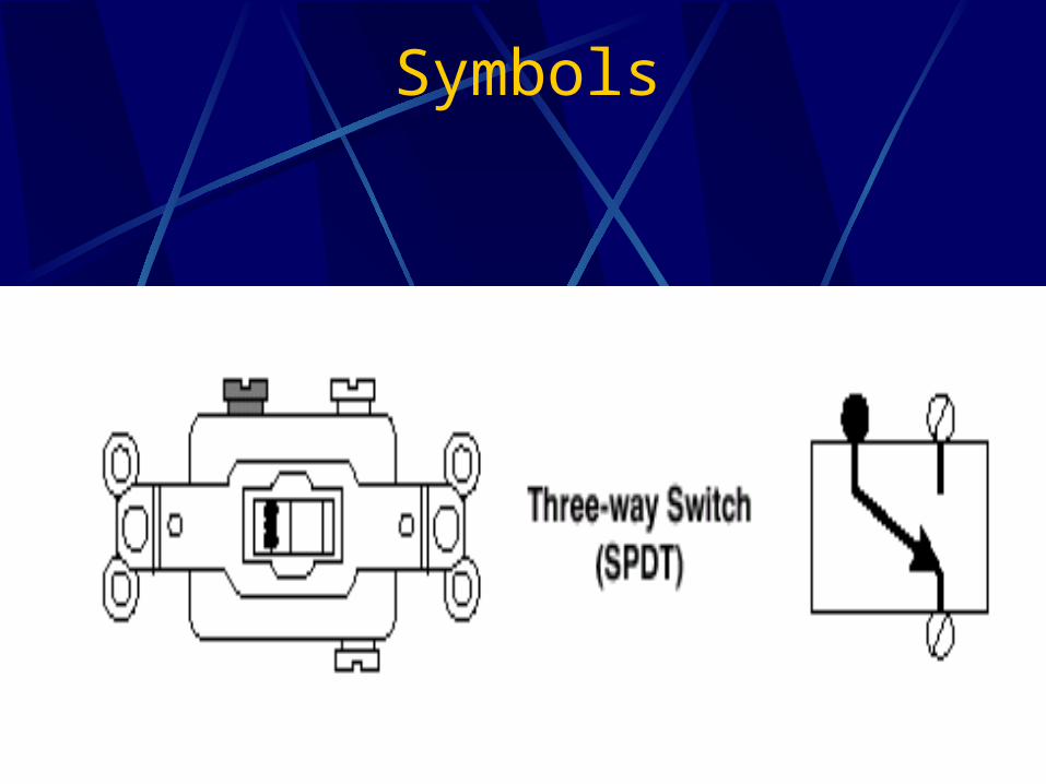
Diagramming-3 way switches
3-way switches are always used in pairs.
They are needed when one wishes to control a light from two different locations.
Diagramming-3 way switches
3-way switches have three screws or terminals, one is called control or common terminal.
It is often darker colored than the other two terminals.
The other two terminals are called traveler terminals.
Diagramming-3 way switches
When the toggle switch is in one position, the common terminal carries current to one traveler terminal.
Diagramming-3 way switches
When the toggle switch is in the other position, the common terminal carries current to the other traveler terminal.
Diagramming-3 way switches
When diagramming and wiring 3-way switches, the hot current always enters the control terminal of one of the switches and always exits out of the control terminal of the other switch.
Diagramming-3 way switches
The traveler terminals from one of the switches must connect to the traveler terminals of the other switch with no interference.
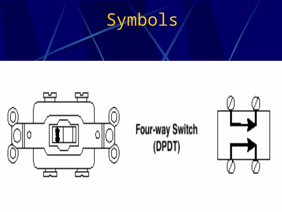
Diagramming-4 way switches
4-way switches are used to control the same light(s) from three or more locations.
One or more 4-way switches must be used with two 3-way switches.
Diagramming-4 way switches
There are four terminals on a 4-way switch and are all considered traveler terminals.
3-way switches are always wired on ends where switching is needed, and the 4-way switches are wired between the two 3-way switches.
Diagramming-4 way switches
Two traveler terminals from the 4-way switch connect to the two traveler terminals from one of the 3-way switches.
The other two traveler terminals from the 4-way switch connect to the two traveler terminals of the other 3-way switch.
Diagramming-4 way switches
When more than one 4-way switch is used, the traveler terminals connect from one switch to the next.
Diagramming
A combination single-pole switch and receptacle is used when a switch and receptacle are desired in the same box.
In most cases, the receptacle is always wired “hot” and the switch is used to control a light or series of lights.
Objective 3
Draw and explain diagrams of circuits using keyless
lampholders, pull-chain lampholders, duplex receptacles,
and single-pole switches.
Diagramming
How do you diagram electrical circuits using keyless lampholders, pull-chain lampholders, duplex receptacles, and single-pole switches?
Diagramming
Many different wiring applications can be completed using keyless lampholders, pull-chain lampholders, duplex receptacles, and single-pole switches.
Diagramming
Several examples of circuits and diagrams will follow.
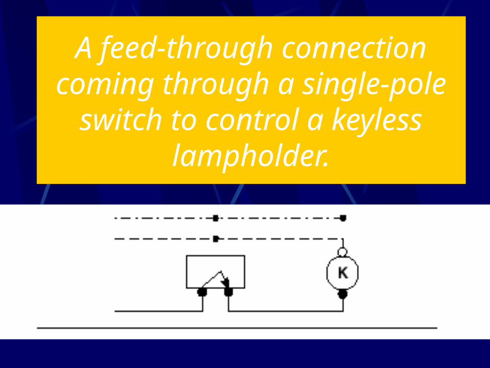
A feed-through connection coming through a single-pole
switch to control a keyless lampholder.
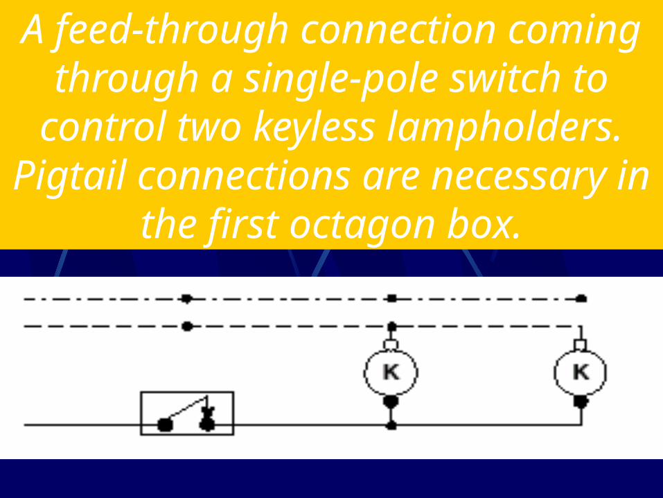
A feed-through connection coming through a single-pole switch to
control two keyless lampholders. Pigtail connections are necessary in
the first octagon box.
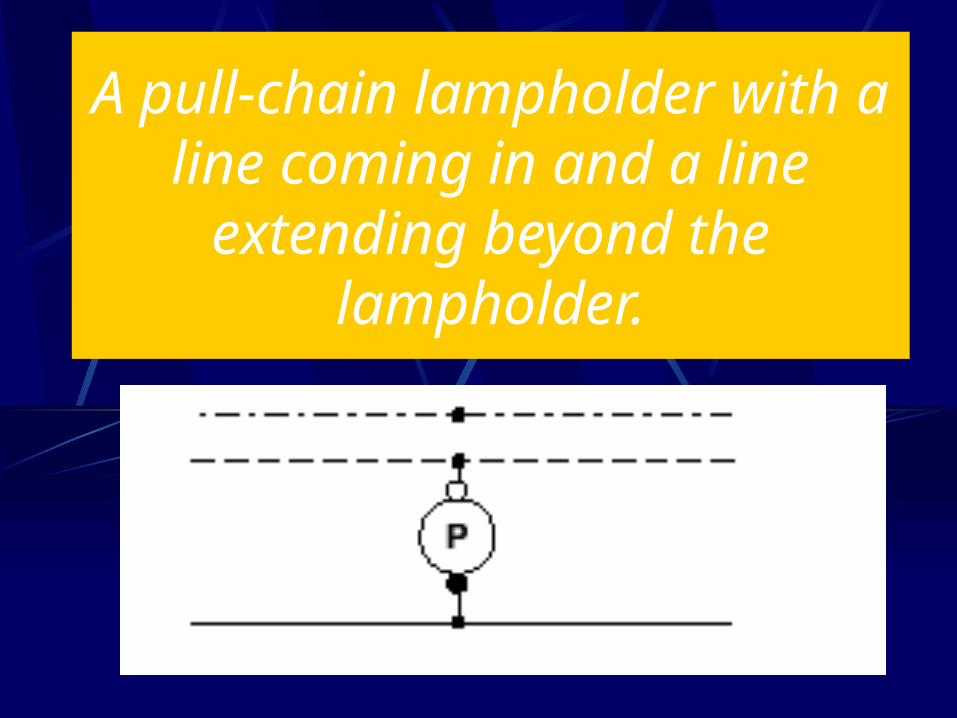
A pull-chain lampholder with a line coming in and a line
extending beyond thelampholder.
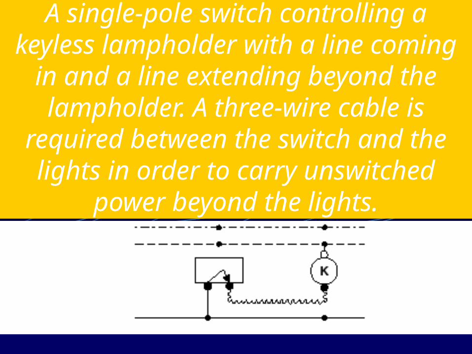
A single-pole switch controlling a keyless lampholder with a line coming
in and a line extending beyond the lampholder. A three-wire cable is
required between the switch and the lights in order to carry unswitched
power beyond the lights.
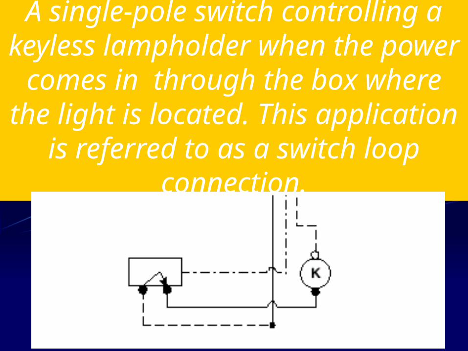
A single-pole switch controlling a keyless lampholder when the power
comes in through the box where the light is located. This application
is referred to as a switch loop connection.
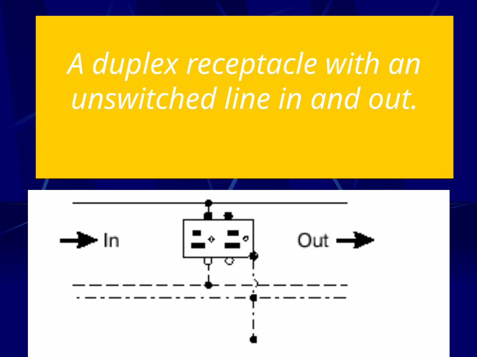
A duplex receptacle with an unswitched line in and out.
Draw and explain diagrams of circuits using lampholders with
3-way and 4-way switches.
Objective 4:
How do you diagram circuits using lampholders with 3-way
and 4-way switches?
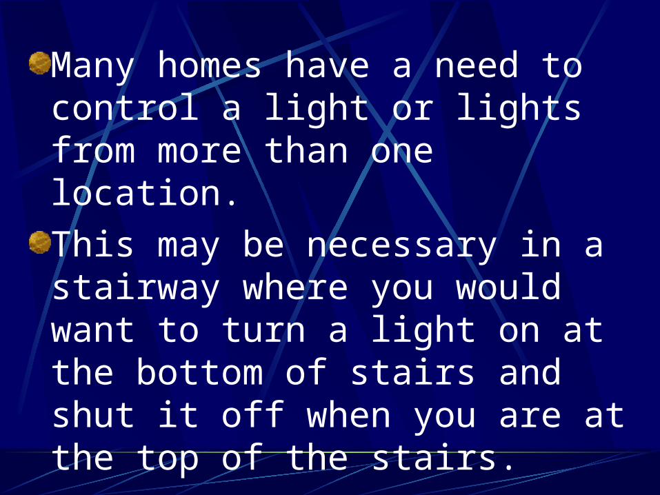
Many homes have a need to control a light or lights from more than one location.
This may be necessary in a stairway where you would want to turn a light on at the bottom of stairs and shut it off when you are at the top of the stairs.
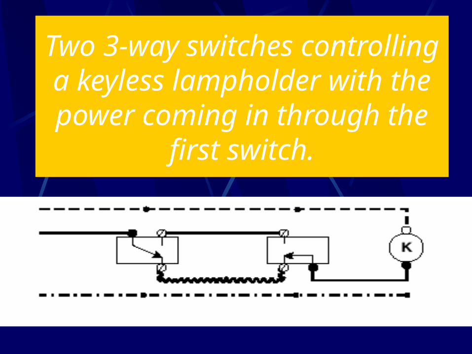
Two 3-way switches controlling a keyless lampholder with the power coming in through the
first switch.
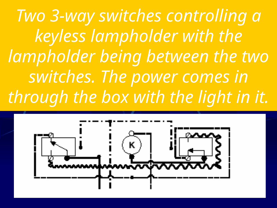
Two 3-way switches controlling a keyless lampholder with the
lampholder being between the two switches. The power comes in
through the box with the light in it.
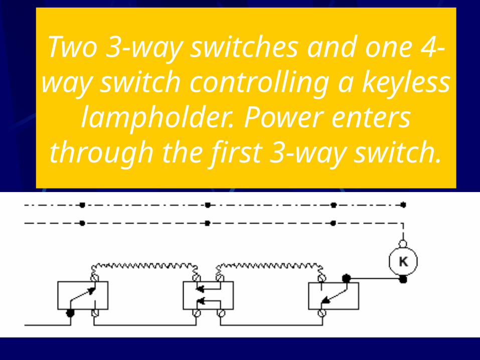
Two 3-way switches and one 4-way switch controlling a
keyless lampholder. Power enters through the first 3-way
switch.
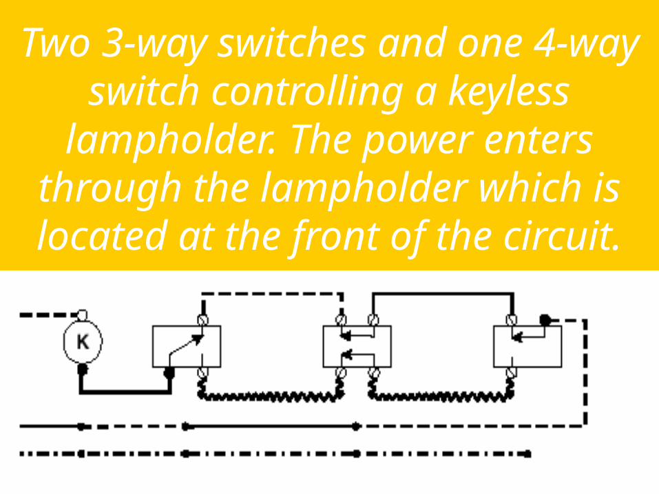
Two 3-way switches and one 4-way switch controlling a keyless
lampholder. The power enters through the lampholder which is located at the front of the circuit.
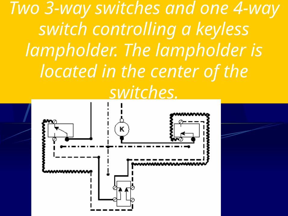
Two 3-way switches and one 4-way switch controlling a keyless
lampholder. The lampholder is located in the center of the
switches.
Draw and explain diagrams of circuits using a combination
single-pole switch and receptacle with a lampholder and applications
where receptacles are split for switching.
How do you diagram circuits using a combination single-pole
switch and receptacle with a lampholder and applications
where receptacles are split for switching?
In special situations, you may need to have the switch and receptacle located in the same box.
In other situations, a duplex receptacle could be used for plugging in a table lamp that could be turned “on” and “off” using a wall switch.
The other half of the receptacle could be used for a clock or other electrical device that would require power at all times.
The following diagrams will demonstrate how to diagram and wire these applications.

A combination single-pole switch and receptacle and a keyless lampholder.
The power comes in through the switch and receptacle, the receptacle is wired
“hot” at all times
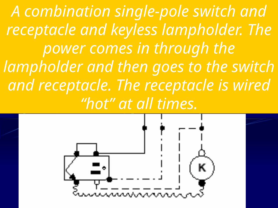
A combination single-pole switch and receptacle and keyless lampholder. The power comes in through the lampholder
and then goes to the switch and receptacle. The receptacle is wired
“hot” at all times.
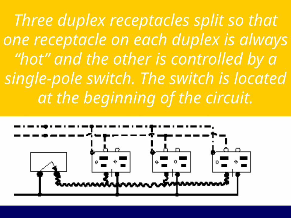
Three duplex receptacles split so that one receptacle on each duplex is
always “hot” and the other is controlled by a single-pole switch. The switch is located at the beginning of the circuit.
Review
1. Identify and draw various symbols used in drawing wiring diagrams or schematics.
2. What rules should be followed in diagramming various circuits.
Review
3. Draw and explain diagrams of circuits using keyless lampholders, pull-chain lampholders, duplex receptacles, and single-pole switches.
Review
4. Draw and explain diagrams of circuits using lampholders with 3-way and 4-way switches.
5. Draw and explain diagrams of circuits using a combination single-pole switch and receptacle with a lampholder and applications where receptacles are split for switching.