Embed Size (px)
Citation preview

MECHANICAL ENGINE CONTROLS CHX8000, CHX8100, CHX8300, CHX8500,
CHX8600 and CHX8800 SERIES
w w w . s e a s t a r s o l u t i o n s . c o m
®
Before you do it your way,
please try it our way.
MANUFACTURED BYMARINE ACQUISITION INCORPORATED
DBA SEASTAR SOLUTIONSU.S.A.
MEMBERINSTALLATION INSTRUCTIONS
AND OWNERS MANUAL
mt3pro-trimsingle stwin s
CHX8300
CHX8100
CHX8000
xtremech2200ch2300
Part # ISCHX80, Rev 1, 10/2016
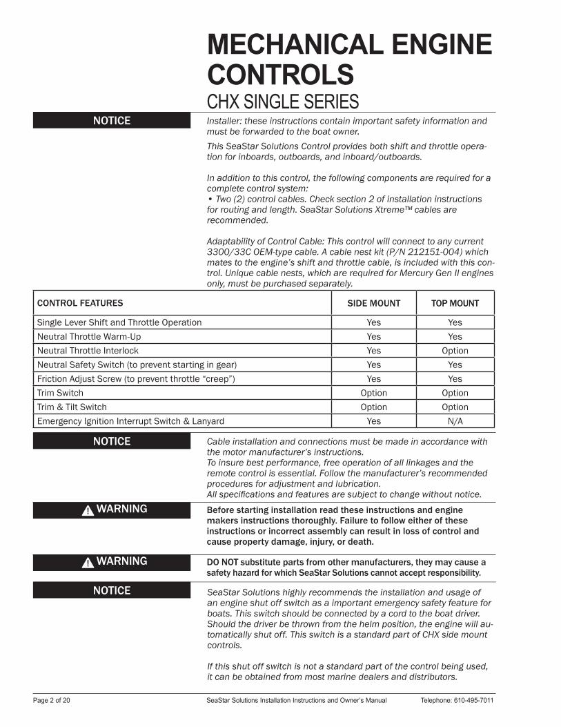
MECHANICAL ENGINECONTROLSCHX SINGLE SERIESInstaller: these instructions contain important safety information and must be forwarded to the boat owner.
NOTICE
Before starting installation read these instructions and engine makers instructions thoroughly. Failure to follow either of these instructions or incorrect assembly can result in loss of control and cause property damage, injury, or death.
DO NOT substitute parts from other manufacturers, they may cause a safety hazard for which SeaStar Solutions cannot accept responsibility.
WARNING
WARNING
Cable installation and connections must be made in accordance with the motor manufacturer’s instructions. To insure best performance, free operation of all linkages and the remote control is essential. Follow the manufacturer’s recommended procedures for adjustment and lubrication.All specifications and features are subject to change without notice.
NOTICE SeaStar Solutions highly recommends the installation and usage of an engine shut off switch as a important emergency safety feature for boats. This switch should be connected by a cord to the boat driver. Should the driver be thrown from the helm position, the engine will au-tomatically shut off. This switch is a standard part of CHX side mount controls.
If this shut off switch is not a standard part of the control being used, it can be obtained from most marine dealers and distributors.
This SeaStar Solutions Control provides both shift and throttle opera-tion for inboards, outboards, and inboard/outboards.
In addition to this control, the following components are required for a complete control system:• Two (2) control cables. Check section 2 of installation instructions for routing and length. SeaStar Solutions Xtreme™ cables are recommended.
NOTICE
CONTROL FEATURES SIDE MOUNT TOP MOUNT
Single Lever Shift and Throttle Operation Yes YesNeutral Throttle Warm-Up Yes YesNeutral Throttle Interlock Yes OptionNeutral Safety Switch (to prevent starting in gear) Yes YesFriction Adjust Screw (to prevent throttle “creep”) Yes YesTrim Switch Option OptionTrim & Tilt Switch Option OptionEmergency Ignition Interrupt Switch & Lanyard Yes N/A
Page 2 of 20 SeaStar Solutions Installation Instructions and Owner’s Manual Telephone: 610-495-7011
Adaptability of Control Cable: This control will connect to any current 3300/33C OEM-type cable. A cable nest kit (P/N 212151-004) which mates to the engine’s shift and throttle cable, is included with this con-trol. Unique cable nests, which are required for Mercury Gen II engines only, must be purchased separately.
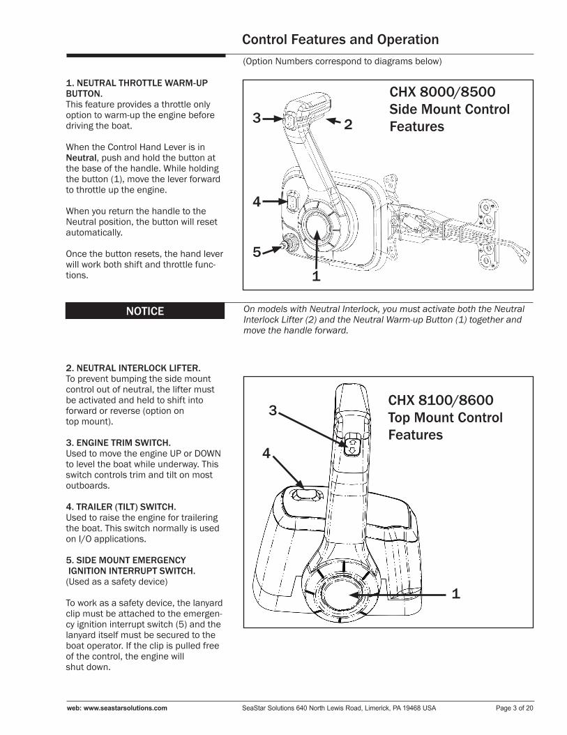
Control Features and Operation
1. NEUTRAL THROTTLE WARM-UP BUTTON. This feature provides a throttle only option to warm-up the engine before driving the boat.
When the Control Hand Lever is in Neutral, push and hold the button at the base of the handle. While holding the button (1), move the lever forward to throttle up the engine.
When you return the handle to the Neutral position, the button will reset automatically.
Once the button resets, the hand lever will work both shift and throttle func-tions.
(Option Numbers correspond to diagrams below)
NOTICE On models with Neutral Interlock, you must activate both the Neutral Interlock Lifter (2) and the Neutral Warm-up Button (1) together and move the handle forward.
2. NEUTRAL INTERLOCK LIFTER. To prevent bumping the side mount control out of neutral, the lifter must be activated and held to shift into forward or reverse (option on top mount).
3. ENGINE TRIM SWITCH. Used to move the engine UP or DOWN to level the boat while underway. This switch controls trim and tilt on most outboards.
4. TRAILER (TILT) SWITCH. Used to raise the engine for trailering the boat. This switch normally is used on I/O applications.
5. SIDE MOUNT EMERGENCY IGNITION INTERRUPT SWITCH. (Used as a safety device)
To work as a safety device, the lanyard clip must be attached to the emergen-cy ignition interrupt switch (5) and the lanyard itself must be secured to the boat operator. If the clip is pulled free of the control, the engine will shut down.
1
CHX 8100/8600Top Mount ControlFeatures
5
4
3 2
1
3
4
CHX 8000/8500Side Mount ControlFeatures
web: www.seastarsolutions.com SeaStar Solutions 640 North Lewis Road, Limerick, PA 19468 USA Page 3 of 20

STEP 2. Allow adequate clearance under the console or in the gunwale for the cables AND allow a minimum of 36" from the cable nest con-nection with no restraint. When supporting the cables beyond 36", do not tie or clamp tightly.
STEP 3. After a suitable location for the control is determined, use the separate mounting template.
STEP 4. Closely follow the instructions provided on the template. Cut and drill the mounting holes required.
On all models, the cover will have to be removed to expose the mount-ing holes.
SECTION 1: LOCATION OF CONTROL.
Installation
Measure the cable routing path from the control head connection to the engine connection.
TOOLS FOR INSTALLATION:Phillips head screwdrivers Standard slot screwdriverSaber saw 4 1/4" Hole saw (optional)Power drill 7/32" and 17/64" drill bits3/8" box end wrench Multimeter (optional)5/8” or 16mm deep well socket Ratchet wrench
SECTION 2: MEASURING THE CABLES.
INBOARDS AND STERNDRIVES:
OUTBOARDS:
Measure from the control connection—along an unobstructed cable routing—to the center of the outboard engine.
Add four (4) feet to the measurement to allow for a loop which pro-vides unrestricted engine movement. Round UP to the next whole foot and order the required cable part number.
(Last two digits of the SeaStar Solutions cable number equal the length of the cable in feet.)
Measure from the control connection—along an unobstructed cable routing—to the shift or throttle connection. Round this dimension UP to the next whole foot and order the required cable part number.
(Last two digits of the SeaStar Solutions cable number equal the length of the cable in feet.)
Page 4 of 20 SeaStar Solutions Installation Instructions and Owner’s Manual Telephone: 610-495-7011
STEP 1. Allow adequate clearance for hand lever swing (forward and reverse positions).

Installation of CablesA. BEND RADIUS. When routing the control cables, select a path with the minimum number of bends, making the bends as large as possible. Sharp or frequent bends will result in difficult throttle or shift control, loss of motion, and premature cable wear. DO NOT MAKE BENDS OF LESS THAN THE RECOMMENDED MINIMUM BEND RADIUS AS NOTED BELOW.
B. SUPPORTING THE CABLE. Do not tie or clamp the cable within 36 inches of the control. When supporting the cable beyond 36 inches of the control, cables should be loosely clamped or tied for support at regular intervals.
Cable Type MinimumBend Radius
Standard 8"Xtreme 4"
For best performance, SeaStar Solutions recommends using Xtreme cables with this control.
Cables must not be bundled together with electrical wiring.Cables must not rest on sharp edges which can cause chafing.
CAUTION
C. CABLE ROUTING. Cables shall not be installed in areas of excess heat such as on, or close to, exhaust manifolds where temperatures may exceed 212°F (100°C).
web: www.seastarsolutions.com SeaStar Solutions 640 North Lewis Road, Limerick, PA 19468 USA Page 5 of 20

Cable Connection GuidePUSH to OPEN THROTTLE
STARBOARD INSTALLATION CENTER INSTALLATION
MANUFACTURERCABLE
NEST KITTHROTTLE
LEVERCABLE
NEST KITTHROTTLE
LEVER
Mercury 18 & 25 HP #1 #1 #1 #1
Johnson/Evinrude #1 #1 #1 #1
BRP/OMC I/O #1 #1 #1 #1
Yamaha 90HP & up #1 #1 #1 #1
US Marine #1 #1 #1 #1
Suzuki #1 #1 #1 #1
PULL to OPEN THROTTLE
STARBOARD INSTALLATION CENTER INSTALLATION
MANUFACTURERCABLE
NEST KITTHROTTLE
LEVERCABLE
NEST KITTHROTTLE
LEVER
MerCruiserMercury I/O & OB
#2 #2 #2 #2
Volvo #2 #2 #2 #2
Yamaha 70HP & Under #2 #2 #2 #2
Honda #2 #2 #2 #2
Nissan/Tohatsu #2 #2 #2 #2
PUSH for FORWARD SHIFT
STARBOARD INSTALLATION CENTER INSTALLATION
MANUFACTURERCABLE
NEST KITSHIFTLEVER
CABLE NEST KIT
SHIFTLEVER
Volvo I/O & Inboards #3 #3 #4 #4
3300 Cables #3 #3 #4 #4
Mercury 18 & 25 HP #5/6 #6 #7/8 #7
Inboards #3 #3 #4 #4
PULL for FORWARD SHIFT
STARBOARD INSTALLATION CENTER INSTALLATION
MANUFACTURERCABLE
NEST KITSHIFTLEVER
CABLE NEST KIT
SHIFTLEVER
3300 Cables #4 #4 #3 #3
MerCruiserMercury I/O & OB
#7/8 #7 #5/6 #6
BRP/OMC I/OEvinrude/Johnson
#7/8 #8 #5/6 #5
Honda/Nissan/Suzuki #4 #4 #3 #3
Tohatsu/US Marine #4 #4 #3 #3
Yamaha #4 #4 #3 #3
Inboards #4 #4 #3 #3
Cable Mounting Diagram
SECTION 3: SHIFT & THROTTLE CABLE CONNECTION-CONTROL END. •PUSH/PULL refer to the direction of cable motion to shift into “for-ward” or to “open” the throttle.•Refer to the appropriate manufacturer’s manual for shift and throttle direction and adjustments.•Numbered holes on mechanism chassis correspond to holes in shift and throttle levers (for example: connect cable mount to hole 4 on chassis and cable end fitting to hole 4 on lever).•Cables and wiring should be pre-installed on control before final mounting is made.
NOTE:I/O = Inboard/Outboard or Sterndrive.O/B = Outboard.
Page 6 of 20 SeaStar Solutions Installation Instructions and Owner’s Manual Telephone: 610-495-7011
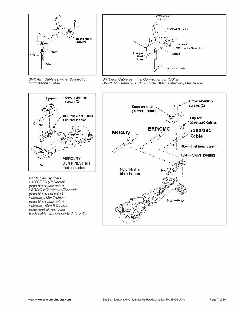
Shift Arm Cable Terminal Connectionfor 3300/33C Cable.
Shift Arm Cable Terminal Connection for “OS” is BRP/OMC/Johnson and Evinrude. “KM” is Mercury, MerCruiser.
Cable End Options• 3300/33C (Universal)(note black nest color)• BRP/OMC/Johnson/Evinrude (note blacknest color)• Mercury, MerCruiser (note black nest color)• Mercury Gen II Cables (note neutral nest color)Each cable type connects differently.
MERCURYGEN II NEST KIT(not included)
web: www.seastarsolutions.com SeaStar Solutions 640 North Lewis Road, Limerick, PA 19468 USA Page 7 of 20

Throttle Cable must be free of load (NO LOAD) when throttle lever is in the idle position to prevent hard shifting.
NOTICE
STEP 1. Make sure the Control is in NEUTRAL DETENT.
STEP 2. The Engine Throttle Lever should rest lightly against the “Idle Stop” on the carburetor.
STEP 3. Connect the Throttle Cable to the Engine Throttle Lever.
STEP 4. Before connecting the shift lever to transmission lever, put both the control lever and the transmission lever into forward gear position. Adjust the cable end to the position where it easily slides onto transmission lever.
STEP 5. If using 3300/33C cables, tighten all jamb nuts against adaptors.
Please Note: This figure does not repre-sent any particular engine.
SECTION 5: ELECTRICAL CONNECTIONS.
This control is provided with a Neutral Safety Switch. This switch is used to prevent the engine from starting in gear.
Use a battery-powered test light or test meter to check continuity.NOTICE
STEP 1. With the Control in NEUTRAL, connect one wire of the tester to the common terminal, and one wire to the “NO” (Normally Open) Terminal. The test light MUST light.
STEP 2. Connect the neutral safety switch between the ignition switch (start lead) and the starter solenoid.
Use a multimeter or continuity tester to make sure that there is electrical continuity only when the control is in neutral position. When the control is in forward or reverse gear there must not be electrical continuity. The multimeter or tester should show an open circuit.
CAUTION
NEUTRAL SAFETY SWITCH.
TRIM AND TILT.
SECTION 4: SHIFT & THROTTLE CABLE CONNECTION-ENGINE END. The throttle cable must be disconnected from the motor before making motor idle adjustments. Adjustment of the motor idle while the throttle cable is connected to the motor may cause jamming action against the idle stop. As a result, the control may not function properly and damage to the control, the cable and/or the motor may occur.
CAUTION
Page 8 of 20 SeaStar Solutions Installation Instructions and Owner’s Manual Telephone: 610-495-7011
Refer to the following wiring diagrams for the correct “Trim” and “Tilt” switch connections and wire accordingly.

Abbreviations:DN = DownUP = Up
Note for Tilt:
1. Connect Blue and Green together, then connect to engine tilt signal wire.
2. Connect Red to engine power wire.
3. Not all engines are wired the same, espe-cially older engines. Check with the engine manufacturer for wir-ing specifications.
4. Use either the upper or lower Tilt switch to bring Tilt UP. To bring Tilt DOWN, use Trim DOWN switch.
This switch includes a lanyard clip which holds the plunger of the switch in position to allow engine operation. A lanyard extends from the clip and is connected securely to the operator. If the operator moves away from the controls, the clip is pulled free, releasing the plunger and stopping the engine.
OPERATION OF IGNITION INTERRUPT SWITCH.
STEP 1. Before each motor start, check that the Lanyard Fork Clip is properly seated over the switch and rotates freely.
STEP 2. Inspect the lanyard. If it is cut, worn or frayed, it must be replaced.
STEP 3. Start the engine.
STEP 4. Test the switch by pulling the lanyard fork clip free from the switch. The engine should stop.
If engine fails to stop, recheck all wiring. Should the engine fail to start or stop, or resume running with the lanyard fork removed, consult your local marine dealer for assistance. Do not change the length of the lanyard or use another manufacturer’s lanyard on this interrupt switch. Either may affect switch operation. Misuse, misapplication, unauthorized modifications, or incorrect installation of this safety devise could result in serious bodily injury or death.
WARNING
INBOARD = PURPLE WIRES OUTBOARD = BLACK WIRES
web: www.seastarsolutions.com SeaStar Solutions 640 North Lewis Road, Limerick, PA 19468 USA Page 9 of 20
IGNITION INTERRUPT SWITCH
Color Key:B = BlueG = GreenR = Red
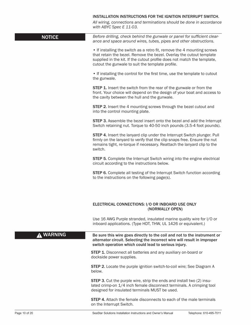
INSTALLATION INSTRUCTIONS FOR THE IGNITION INTERRUPT SWITCH. All wiring, connections and terminations should be done in accordance with ABYC Spec E 11-03.
Before drilling, check behind the gunwale or panel for sufficient clear-ance and space around wires, tubes, pipes and other obstructions.
• If installing the switch as a retro fit, remove the 4 mounting screws that retain the bezel. Remove the bezel. Overlay the cutout template supplied in the kit. If the cutout profile does not match the template, cutout the gunwale to suit the template profile.
• If installing the control for the first time, use the template to cutout the gunwale.
STEP 1. Insert the switch from the rear of the gunwale or from the front. Your choice will depend on the design of your boat and access to the cavity between the hull and the gunwale.
STEP 2. Insert the 4 mounting screws through the bezel cutout and into the control mounting plate.
STEP 3. Assemble the bezel insert onto the bezel and add the Interrupt Switch retaining nut. Torque to 40-50 inch pounds (3.5-4 foot pounds).
STEP 4. Insert the lanyard clip under the Interrupt Switch plunger. Pull firmly on the lanyard to verify that the clip snaps free. Ensure the nut remains tight, re-torque if necessary. Reattach the lanyard clip to the switch.
STEP 5. Complete the Interrupt Switch wiring into the engine electrical circuit according to the instructions below.
STEP 6. Complete all testing of the Interrupt Switch function according to the instructions on the following page(s).
ELECTRICAL CONNECTIONS: I/O OR INBOARD USE ONLY (NORMALLY OPEN)
Use 16 AWG Purple stranded, insulated marine quality wire for I/O or inboard applications. (Type HDT, THW, UL 1426 or equivalent.)
Be sure this wire goes directly to the coil and not to the instrument or alternator circuit. Selecting the incorrect wire will result in improper switch operation which could lead to serious injury.
WARNING
STEP 1. Disconnect all batteries and any auxiliary on-board or dockside power supplies.
STEP 2. Locate the purple ignition switch-to-coil wire; See Diagram A below.
STEP 3. Cut the purple wire, strip the ends and install two (2) insu-lated crimp-on 1/4 inch female disconnect terminals. A crimping tool designed for insulated terminals MUST be used.
STEP 4. Attach the female disconnects to each of the male terminals on the Interrupt Switch.
NOTICE
Page 10 of 20 SeaStar Solutions Installation Instructions and Owner’s Manual Telephone: 610-495-7011

STEP 5. Recheck all connections.
STEP 6 Install Lanyard with the Fork Clip seated on the Plunger.
STEP 7. Reconnect battery.
STEP 8. Start engine. If engine does not start: disconnect battery, recheck all electrical connections, reconnect battery and restart engine.
STEP 9. Remove Lanyard. Engine should stop immediately.
Diagram AI/O and Inboard Wiring(basic wiring; no specific manufacturer)
ELECTRICAL CONNECTIONS: OUTBOARD USE ONLY (NORMALLY CLOSED)
Use 16 AWG Black stranded, insulated marine quality wire for all outboard applications. (Type HDT, THW, UL 1426 or equivalent.)
This interrupt switch is designed for use with outboard motors equipped with grounding type emergency stop circuits only!
CAUTION
STEP 1. Disconnect all batteries and any auxiliary on-board or dockside power supplies.
STEP 2. Remove Engine Cover.
STEP 5. Strip one end of each wire and crimp on an insulated 1/4 inch female disconnect terminal. A crimping tool designed for insulated terminals MUST be used.
web: www.seastarsolutions.com SeaStar Solutions 640 North Lewis Road, Limerick, PA 19468 USA Page 11 of 20
STEP 4. Measure and cut two lengths of black 16 AWG marine quality wire of sufficient length to connect one Interrupt Switch terminal to the Emergency Stop Wire and the other terminal to a System Ground. (See Diagram B.)
STEP 3. Locate the correct color emergency stop wire for your motor. (See Reference Table 1.)

STEP 6. Attach the female disconnects to each of the male terminals on the Interrupt Switch.
STEP 7. Attach the other end of one wire to the Emergency Stop Wire, using a suitable insulated wire connecting device. (See Reference Table 1 and Diagram B.)
STEP 8. Attach the other end of the second wire to the ground point, using a suitable insulated wire connection deice as shown in Diagram B below.
STEP 9. Recheck all connections. Install the Lanyard with the Fork Clip seated over the Plunger.
STEP 10. Replace engine cover and reconnect battery.
STEP 11. Start engine. If engine does not start: a) disconnect battery; b) remove engine cover; c) recheck all electrical connections; d) replace engine cover; and e) restart engine.
Remove Lanyard. Engine should stop immediately.
If engine fails to stop, recheck all wiring. Should the engine fail to start or stop or resume running with the lanyard fork removed, consult your local marine dealer for assistance.
CAUTION
WIRE COLOR TABLEFOR LATE MODEL OUTBOARDS
ENGINE COLORDaihatsu Solid Brown
EvinrudeBefore 1969
Black with Yellow StripeSolid Blue
Force Solid White
JohnsonBefore 1969
Black with Yellow StripeSolid Blue
Mariner Black with Yellow StripeMercury Black with Yellow StripeNissan Solid Brown
OMCBefore 1969
Black with Yellow StripeSolid Blue
Suzuki Solid Brown
US Marine Blue with Black Stripe orSolid Blue
Yamaha Black with Yellow Stripe
Reference Table 1.
Diagram B.Outboard Wiring.
Page 12 of 20 SeaStar Solutions Installation Instructions and Owner’s Manual Telephone: 610-495-7011
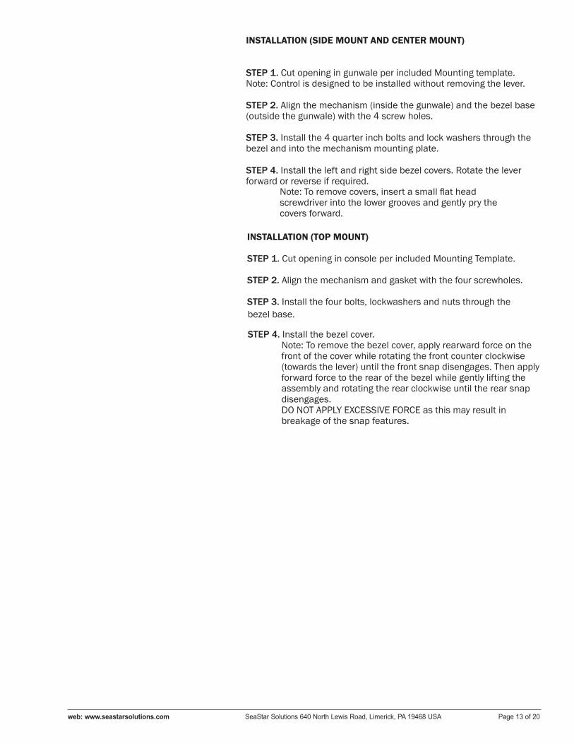
INSTALLATION (SIDE MOUNT AND CENTER MOUNT)
STEP 1. Cut opening in gunwale per included Mounting template. Note: Control is designed to be installed without removing the lever.
STEP 2. Align the mechanism (inside the gunwale) and the bezel base (outside the gunwale) with the 4 screw holes.
STEP 3. Install the 4 quarter inch bolts and lock washers through the bezel and into the mechanism mounting plate.
bezel base.
web: www.seastarsolutions.com SeaStar Solutions 640 North Lewis Road, Limerick, PA 19468 USA Page 13 of 20
STEP 4. Install the left and right side bezel covers. Rotate the lever forward or reverse if required.
Note: To remove covers, insert a small flat head screwdriver into the lower grooves and gently pry the covers forward.
INSTALLATION (TOP MOUNT)
STEP 1. Cut opening in console per included Mounting Template.
STEP 2. Align the mechanism and gasket with the four screwholes.
STEP 3. Install the four bolts, lockwashers and nuts through the
STEP 4. Install the bezel cover. Note: To remove the bezel cover, apply rearward force on the front of the cover while rotating the front counter clockwise (towards the lever) until the front snap disengages. Then applyforward force to the rear of the bezel while gently lifting the assembly and rotating the rear clockwise until the rear snap disengages. DO NOT APPLY EXCESSIVE FORCE as this may result inbreakage of the snap features.

CHX8000: SIDE-MOUNT CONTROL GENERAL DIMENSIONS.
General Control Dimensions
CHX8100 TOP-MOUNT CONTROL GENERAL DIMENSIONS.
Page 14 of 20 SeaStar Solutions Installation Instructions and Owner’s Manual Telephone: 610-495-7011

FRICTION ADJUST SCREW.
Exploded View CHX8000
Adjustment of this screw enables the friction in the throttle operating mechanism to be increased and prevent unwanted handle movement. To adjust, place the lever in the forward or reverse throttle position (just beyond the shift position). Remove the cover and adjust the fric-tion adjust screw: turning the screw clockwise increases the friction. Do not over-tighten.
FRICTION ADJUST SCREW.
Exploded View CHX8100
Adjustment of this screw enables the friction in the throttle operating mechanism to be increased and prevent unwanted handle movement. To adjust, place the lever in the forward or reverse throttle position (just beyond the shift position). Remove the cover and adjust the fric-tion adjust screw: turning the screw clockwise increases the friction. Do not over-tighten.
Friction Adjust Screw
Friction Adjust Screw
web: www.seastarsolutions.com SeaStar Solutions 640 North Lewis Road, Limerick, PA 19468 USA Page 15 of 20

Service Parts Kits
All service parts can be purchased from your local SeaStar Solutions Distributor.
KIT NUMBER KIT NAME AND DESCRIPTION MODEL USED ON212151-003 Cable Nest and Connection Kit with Mercury Gen II Nest All051801-023 Neutral Safety Switch All
CHX8000 REPLACEMENT PARTSNeutral Throttle Warm-up Kit (Side Mount)Tilt Switch KitInterrupt Switch Kit, I/O & InboardInterrupt Switch Kit, Outboard
CHX8100 REPLACEMENT PARTSNeutral Throttle Warm-up Kit (Top Mount)Tilt Switch Kit
Page 16 of 20 SeaStar Solutions Installation Instructions and Owner’s Manual Telephone: 610-495-7011

Maintenance Notes1. After a few hours of operation and at frequent intervals thereafter, check all fasteners and the complete control system for security and integrity.
DANGER Loosening or loss of one or more fasteners may cause failure of the control system and could cause property damage, injury, or death.
2. Keep all moving parts free from build-up of salt and other foreign material. This will affect their operation and create control problems.
3. Periodically inspect for corrosion. Any parts affected by corrosion must be replaced. Any replacement hardware must be as originally supplied (i.e. similar material and locking features).
4. Periodically inspect control cables for cracks and other damage. If any is found the cable must be replaced.
5. If cable is stiff in operation, it is unsafe to use and must be replaced immediately.
6. Periodically treat exposed metal components with a marine grade wax.
DANGER DO NOT cover cracks with tape or other sealants. This will create a hazard in which the cable can fail suddenly without warning, resulting in property damage, injury, or death.
Boat builder and boat dealer, please supply these Installation Instructions and Owner’s Manual with the delivery of boat. Boat owner keep these instructions with your boat for future reference. Boat owner consult with your boat builder, boat dealer, or SeaStar Solutions if you have any questions regarding these instructions.
NOTICE
web: www.seastarsolutions.com SeaStar Solutions 640 North Lewis Road, Limerick, PA 19468 USA Page 17 of 20

CHX8000, CHX8300, CHX8500, CHX8800,Mounting TemplateSide Mount ControlFront Mount Installation
This template may not be to scale. Its presence is for information purposes. A separate work template—MT-CHX81 has been included with this control.
NOTICE
Page 18 of 20 SeaStar Solutions Installation Instructions and Owner’s Manual Telephone: 610-495-7011
INTERRUPTSWITCH
TILT SWITCH

NOTICE
CHX8100 AND CHX8600 Mounting TemplateTop Mount Single Lever Control
web: www.seastarsolutions.com SeaStar Solutions 640 North Lewis Road, Limerick, PA 19468 USA Page 19 of 20
This template may not be to scale. Its presence is for information purposes. A separate work template—MT-CHX81—has been included with this control.

© 2016 MARINE ACQUISITION (US) INC.
PART # ISCHX80 10-2016 Rev. 1