Embed Size (px)
Citation preview

Thank you for purchasing a Honda Outboard Motor.
This manual describes the operation and maintenance of the Honda BF35A/45A Outboard Motors. All information in this publication is based on the latest product informa- tion available at the time of printing. Honda Motor Co., Ltd. reserves the right to make changes at any time without notice and without incurring any obligation.
No part of this publication may be reproduced without written permission.
This manual should be considered a permanent part of the Outboard Motor and it must stay with the Outboard Motor if resold.
READ THIS OWNER’S MANUAL CAREFULLY. Pay special attention to these symbols and any instructions that follow.
B Indicates serious injury or death WILL result if instructions are not followed.
B Indicates a strong possibility that serious injury or death may result if instructions are not followed.
w Indicates a possibil- ity that minor injury could result if instructions are not followed.
[NOTICEI Indicates that equipment or property damage could result if instructions are not followed.
Honda Outboard Motors are designed to give safe and dependable service if operated according to instructions. Operating this Outboard Motor requires special effort on your part to ensure your safety and the safety of others.
- Careless oneration or misuse may cause iijury or property damage. Read and understand this owner’s manual before operating the Outboard Motor.
If a problem should arise, or if you have any questions about your Outboard Motor, see an authorized Honda Marine dealer.
HONDA MOTOR CO., LTD. 1990, ALL RIGHTS RESERVED
1
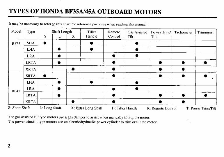
TYPES OF HONDA BF3§A/45A OUTBOARD MOTORS
It may be necessary to refer_tcthis chart for reference purposes when reading this manual
Model
BF35
BF45
S: Short Shaft L: Long Shaft X: Extra Long Shaft H: Tiller Handle R: Remote Control T: Power Trim/Tilt
The gas assisted tilt type motors use a gas damper to assist when manually tilting the motor. The power trim/tilt type motors use an electric/hydraulic power cylinder to trim or tilt the motor.
2
IDENTIFICATION NUMBERS
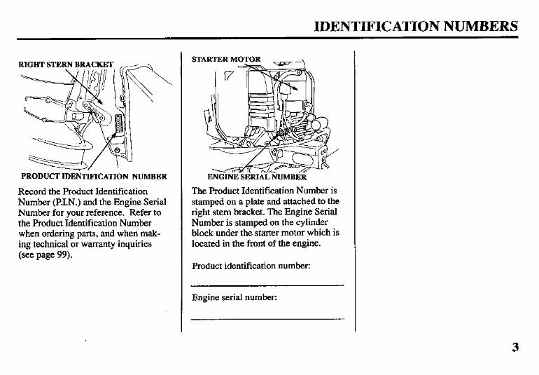
PRODUCT IDENTIFICATION NUMBER
Record the Product Identification Number (RLN.) and the Engine Serial Number for your reference. Refer to the Product Identification Number when ordering parts, and when mak- ing technical or warranty inquiries (see page 99).
STARTER MOTOR - -\
ENGINE~SERIAL NUMBER
The Product Identification Number is. stamped on a plate and attached to the right stem bracket. The Engine Serial Number is stamped on the cylinder block under the starter motor which is located in the front of the engine.
Product identification number:
Engine serial number:
3
CONTENTS
1. SAFKI-Y Safety labels ................................................................ .6 Safety information ...................................................... 7
2. COMPONENT IDENTIFICATION ............................ 8 3. CONTROLS Tiller handle type
Engine start button .................................................... 11 Shift lever .................................................................. 11 Choke knob ............................................................... 11 Throttle grip .............................................................. 12 Throttle opening indicator ........................................ 12 Throttle friction knob ................................................ 12 Engine stop switch .................................................... 13 Emergency stop switch lanyard ................................ 13 Oil pressure indicator light ....................................... Overheat indicator light ............................................ :t
Remote control type Remote control lever ................................................ 15 Neutral release lever ................................................. 16 Ignition switch .......................................................... 16 Emergency stop switch lanyard ................................ 17 Choke/fast idle lever ................................................. 18 Manual choke knob ................................................... I8 Oil pressure indicator light/buzzer ............................ .19 Overheat indicator light/buzzer ................................ 19
Remote control & power trim/tilt type Power trim/tilt switch (remote control lever) ........... 20 Power tilt switch (motor pan) ................................... 21 Trim meter ................................................................ 21 Tachometer ............................................................... 21 Manual relief valve ................................................... 22
Gas assisted tilt type Tilt lever .................................................................... 22
Controls & instruments (common) Tilt lock lever ............................................................ 23 Trim tab ..................................................................... 23 Anode metal .............................................................. 24 Cooling system indicator .......................................... 24 Water intakes ............................................................ 25 Transom angle adjusting rod ..................................... 26 Fuel cap/gauge/vent knob ......................................... 27 Engine over-rev limiter ............................................. 27
4. PRE-OPERATION CHECKS Engine cover removal/installation ............................ 28 Engine oil .................................................................. 29 Fuel level .................................................................. 30 Gasoline containing alcohol ..................................... 3 1 Propeller and cotter Steering
pin ............................................. 32 friction adjustment (common) .................... 32
Remote control friction adjustment .......................... 33 Other checks l Stem bracket ........................................................... 33 l Tool kit ................................................................... 33 l Anodes . . . . . . . . . . . . . . . . . . . . . . . . . . . . . . . . . . . . . . . . . . . . . . . . . . . . . . . . . . . . . . . . . . . . 33
5. STARTING THE ENGINE Fuel line connection .................................................. 34 Starting the engine (Tiller handle type) .................... 36 Starting the engine (Remote control type) ................ 40 Emergencv starting ................................................... 43 Troubcieshooting &rting . . . . . . . . . . . . . . . . . . . . . . . . . . . 48
6. OPERATION problems
Break-in procedure . . . . . . . . . . . . . . . . . . . . . . . . . . . . . . . . . . . . . . . . . . . . . . . . . . . . 49
CONTENTS
Tiller handle type Gearshifting ........................................................... 50 Steering .................................................................. 51 Cruising .................................................................. 5 1
Remote control type Gear shifting .......................................................... 52 Cruising ................................................................. 53
Tilting motor Gas assisted tilt type .............................................. 54 Power trim/tilt type ................................................. 57
Power trim/tilt type Trim meter ............................................................. 58 Power tilt switch (motor pan) ................................ 59 Manual relief valve ................................................ Tilt lock lever ........................................................ 2:
Trim tab adjustment .................................................. 61 Motor protection system
Engine oil pressure and Overheat warning system ...................................... 62 Over-rev limiter ..................................................... 64 Power trim warning system ................................... Anodes ................................................................... El
Shallow water operation ............................................ 66 High altitude operation .............................................. 67
7. STOPPING THE ENGINE Tiller handle type ...................................................... 68 Remote control type .................................................. 70
8. TRANSPORTING ....................................................... 9. CLEANING AND FLUSHING .................................. ;: 10 MAINTENANCE ..................................................... 74
Tool kit and spare parts ............................................. 74
Maintenance schedule ............................................... 76 Engine oil .................................................................. 78 Gear oil ..................................................................... 80 Spark plugs ............................................................... 82 Battery (not included) ............................................... 83 Lubrication ................................................................ 85 Engine fuel filter ....................................................... 86 Fuel tank and filter .................................................... 88 Fuse replacement ...................................................... 89 Propeller .................................................................... 90 Submerged motor ...................................................... 9 1
11. STORAGE ................................................................. 93 12. TROUBLESHOOTING ............................................ 95 13. SPECIFICATIONS ................................................... 97 14. WARRANTY SERVICE .......................................... .99 15. WIRING DIAGRAM .............................................. 100 16. INDEX ..................................................................... 103
5
1. SAFETY
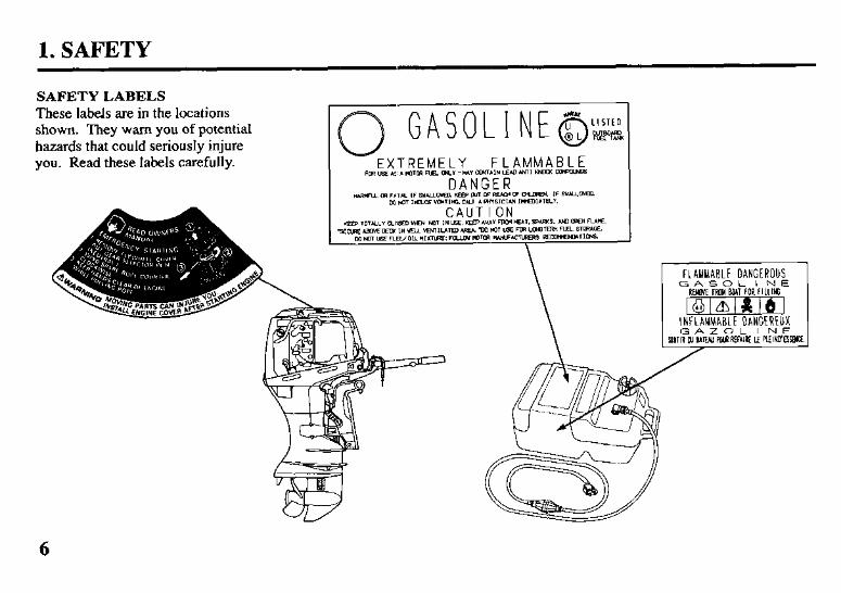
SAFETY LABELS
These labels are in the locations shown. They warn you of potentia1 hazards that could seriously injure you. Read these labels carefully. EXTREMELY FLAMMABLE Frn~4.~~~~~MI-~ICan~INLWunr~-
DANGER
I. SAFETY
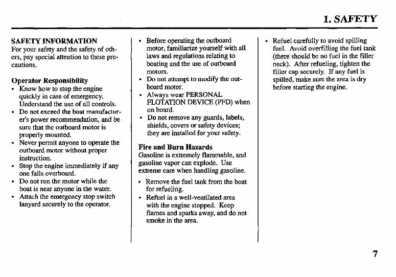
SAFETY INFORMATION For your safety and the safety of oth- ers, pay special attention to these pre- cautions.
Operator Responsibility l Know how to stop the engine
quickly in case of emergency. Understand the use of all controls.
l Do not exceed the boat manufactur- er’s power recommendation, and be sure that the outboard motor is properly mounted.
l Never permit anyone to operate the outboard motor without proper instruction.
l Stop the engine immediately if any one falls overboard.
l Do not run the motor while the boat is near anyone in the water.
l Attach the emergency stop switch lanyard securely to the operator.
l Before operating the outboard motor, familiarize yourself with all laws and regulations relating to boating and the use of outboard motors.
l Do not attempt to modify the out- board motor.
l Always wear PERSONAL FLOTATION DEVICE (PFD) when on board.
l Do not remove any guards, labels, shields, covers or safety devices; they are installed for your safety.
Fire and Burn Hazards Gasoline is extremely flammable, and gasoline vapor can explode. Use extreme care when handling gasoline.
l Remove the fuel tank from the boat for refueling.
l Refuel in a well-ventilated area with the engine stopped. Keep flames and sparks away, and do not smoke in the area.
l Refuel carefully to avoid spilling fuel. Avoid overfilling the fuel tank (there should be no fuel in the filler neck). After refueling, tighten the filler cap securely. If any fuel is spilled, make sure the area is dry before starting the engine.
7
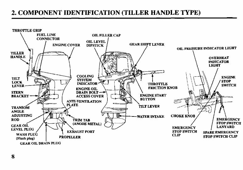
2. COMPONENT IDENTIFICATION (TILLER HANDLE TYPE)
HANDLE
1
ldiir-7 o
THdT w v COOLING
LOCK
THROTTLE GRIP
LEVER on, PReS\SURE INDICATOR LIGHT
STERN BRACKET I
Mi
ACCESS COVER ENGINE START M 0 ANTI-VENTILATION c
D, ATE-
=r THROTTLE
\
OVERHEAT INDICATOR LIGHT
ENGINE STOP “.l”-..CH _____- ~~~
FRICTION KNOB
&l l/l \
WATER INTAKE ‘RIM TAB
WASH PLUG I
I Y...-.-..YL . u
(Flush plug) PROPEL1 -- XR
CHOKE KNOB
/ I
\ EMERGENCY STOP SWITCH
EMERGENCY LANYARD STOP SWITCH CLIP
SPARE EMERGENCY STOP SWITCH CLIP
GEAR OIL DRAIN PLUG
8
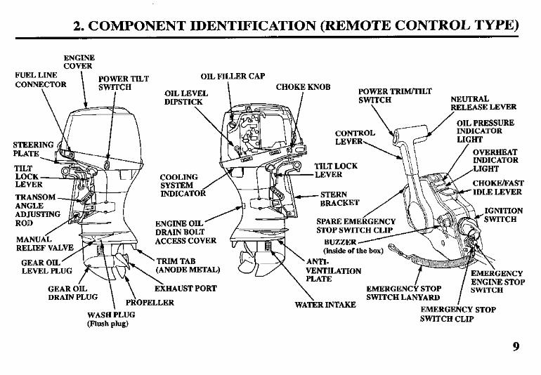
2. COMPONENT IDENTIFICATION (REMOTE CONTROL TYPE)
ENGINE COVER
FUEL LINE CONNECTOR
POWER TILT
\ SWI;rCH
OIL FILLER CAP CHOKE KNOB
I POWER TRIM/TILT SWITCH NEUTRAL
\ RELEASE LEVER
\ - / OIL PRESSURE V INDICATOR
STEERING I I
COOLING /e-r In! CHOKE/FAST IDLE LEVER - STERN
BRACKET /
/
INDICATOR TRANSOM ANGLE
SPARE EMERGENCY ENGINE OIL ’
MANUA< RELIEF VALVE
GEAR OIL /
LEVEL PLUG
ACCESS COVER
ETAL)
GEAR HAUST PORT
~BNTHATION __ .-- r -/ EMERGENCY STOP hAIN
- \ /
I ENGINE
EMERGENCY STOP SWITCH SWITCH LANYARD WA”“” .rwn. .,m
EMERGENCY STOP SWITCH CLIP
DRAIN PLUG \
\ PROPELLER
9
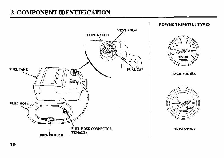
2. COMPONENT IDENTIFICATION
VENT KNOB
FUEL GAUGE /
FUEL CAP
I FiJEL HOSE CONNECTOR (FEMALE)
PRIMER BULB
POWER TRIM/TILT TYPES
TACHOMETER
TRIM METER
10
3. CONTROLS (TILLER HANDLE TYPE)
Engine Start Button R
(reverse) N
EN&NE START BUTTON
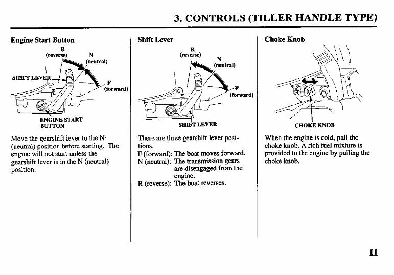
Move the gearshift lever to the N (neutral) position before starting. The engine will not start unless the gearshift lever is in the N (neutral) position.
Shift Lever R
(reverse) N
SHIti LEVER
There are three gearshift lever posi- tions. F (forward): The boat moves forward. N (neutral): The transmission gears
are disengaged from the engine.
R (reverse): The boat reverses.
Choke Knob
CHOKk KNOB
When the engine is cold, pull the choke knob. A rich fuel mixture is provided to the engine by pulling the choke knob.
11
3. CONTROLS (TILLER HANDLE TYPE)
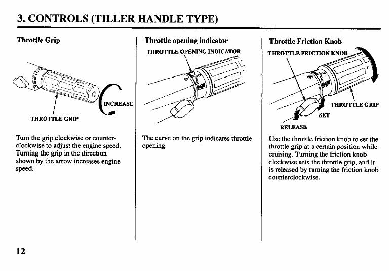
Throttle Grip
THROTTLE GRIP
Turn the grip clockwise or counter- clockwise to adjust the engine speed. Turning the grip in the direction shown by the arrow increases engine speed.
Throttle opening indicator
THROTTLE OIPENING INDICATOR
The curve on the grip indicates throttle opening.
Throttle Friction Knob
RELEASE
Use the throttle friction knob to set the throttle grip at a certain position while cruising. Turning the friction knob clockwise sets the throttle grip, and it is released by turning the friction knob counterclockwise.
12
3. CONTROLS (TILLER HANDLE TYPE)
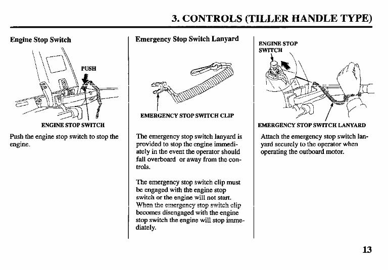
Engine Stop Switch
ENGINE STOP StiTCH
Push the engine stop switch to stop the engine.
Emergency Stop Switch Lanyard
EMERGENCY STOP SWITCH CLIP
The emergency stop switch lanyard is provided to stop the engine immedi- ately in the event the operator should fall overboard or away from the con- trols.
The emergency stop switch clip must be engaged with the engine stop switch or the engine will not start. When the emergency stop switch clip becomes disengaged with the engine stop switch the engine will stop imme- diately.
ENGINE STOP SWITCH \
EMERGENCY STOP SWITCH LANYARD
Attach the emergency stop switch lan- yard securely to the operator when operating the outboard motor.
13
3. CONTROLS (TILLER HANDLE TYPE)
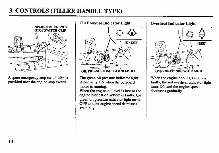
SPARE EMERGENCY ,STOP SWITCH CLIP
A spare emergency stop switch clip is provided near the engine stop switch.
Oil Pressure I’ndicator Light I I- \
OIL PRESSURE INDICATOR LIGHT
The green oil pressure indicator light is normally ON when the outboard motor is running. When the engine oil level is low or the engine lubrication system is faulty, the green oil pressure indicator light turns OFF and the engine speed decreases gradually.
Overheat Indicator Light
OVERHEAT INDICATOR LIGHT
When the engine cooling system is faulty, the red overheat indicator light turns ON and the engine speed decreases gradually.
14
3. CONTROLS (REMOTE CONTROL TYPE)
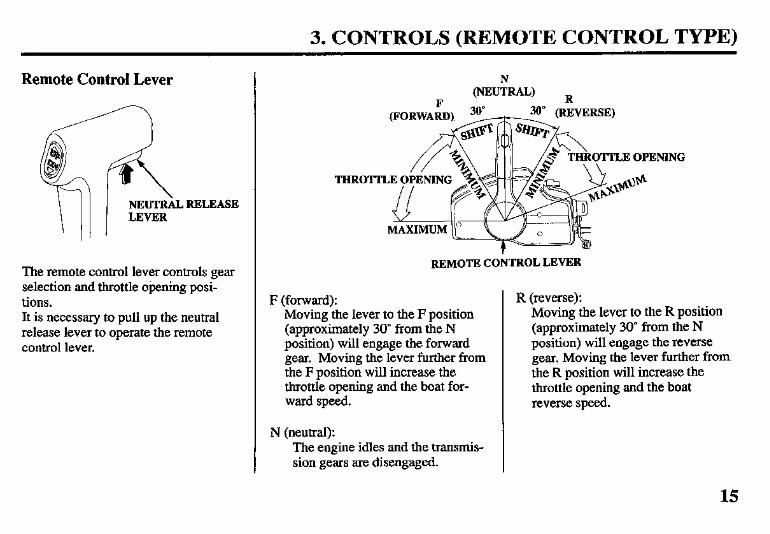
Remote Control Lever
The remote control lever controls gear selection and throttle opening posi- tions. It is necessary to pull up the neutral release lever to operate the remote control lever.
REMOTE CONTROL LEVER
F (forward): Moving the lever to the F position (approximately 30” from the N position) will engage the forward gear. Moving the lever further from the F position will increase the throttle opening and the boat for- ward speed.
N (neutral): The engine idles and the transmis- sion gears are disengaged.
R (reverse): Moving the lever to the R position (approximately 30” from the N position) will engage the reverse gear. Moving the lever further from. the R position will increase the throttle opening and the boat reverse speed.
15
3. CONTROLS (REMOTE CONTROL TYPE)
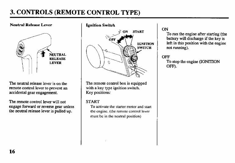
Neutral Release Lever
The neutral release lever is on the remote control lever to prevent an accidental gear engagement.
The remote control lever will not engage forward or reverse gear unless the neutral release lever is pulled up.
Ignition Switch
The remote control box is equipped with a key type ignition switch. Key positions:
START To activate the starter motor and start the engine. (the remote control lever must be in the neutral position)
ON To run the engine after starting (the battery will discharge if the key is left in this position with the engine not running).
OFF To stop the engine (IGNITION OFF).
16
3. CONTROLS (REMOTE CONTROL TYPE)
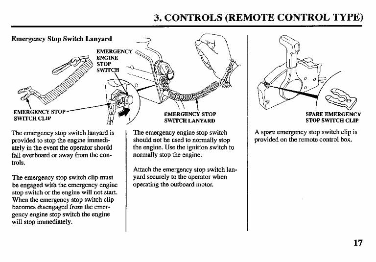
Emergency Stop Switch Lanyard
SWITCH LANYARD
The emergency stop switch lanyard is provided to stop the engine immedi- ately in the event the operator should fall overboard or away from the con- trols.
The emergency stop switch clip must be engaged with the emergency engine stop switch or the engine will not start. When the emergency stop switch clip becomes disengaged from the emer- gency engine stop switch the engine will stop immediately.
The emergency engine stop switch should not be used to normally stop the engine. Use the ignition switch to normally stop the engine.
Attach the emergency stop switch lan- yard securely to the operator when operating the outboard motor.
SPAkE EMERGENCY STOP SWITCH CLIP
A spare emergency stop switch clip is provided on the remote control box.
17
3. CONTROLS (REMOTE CCDNTROL TYPE)
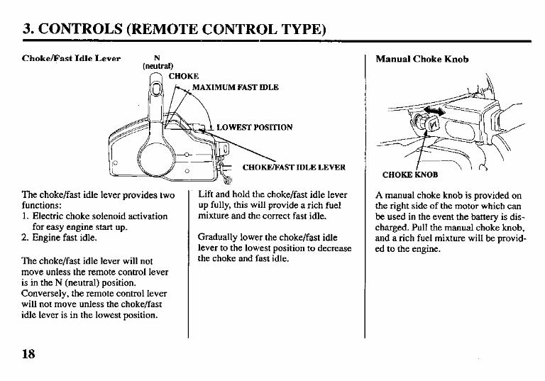
Choke/Fast Idle Lever
n CHOKE XIMUM FAST IDLE
OWEST POSITION
CHOKE/FAST
The choke/fast idle lever provides two functions: 1. Electric choke solenoid activation
for easy engine start up. 2. Engine fast idle.
The choke/fast idle lever will not move unless the remote control lever is in the N (neutral) position. Conversely, the remote control lever will not move unless the choke/fast idle lever is in the lowest position.
IDLE LEVER
Lift and hold the choke/fast idle lever up fully, this will provide a rich fuel mixture and the correct fast idle.
Gradually lower the choke/fast idle lever to the lowest position to decrease the choke and fast idle.
Manual Choke Knob
CHOKE tiOB
A manual choke knob is provided on the right side of the motor which can be used’in the event the battery is dis- charged. Pull the manual choke knob, and a rich fuel mixture will be provid- ed to the engine.
18
3. CONTROLS (REMOTE CONTROL TYPE)
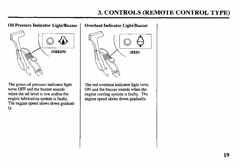
03 Pressure Indicator Light/Buzzer
The green oil pressure indicator light turns OFF and the buzzer sounds when the oil level is low and/or the engine lubrication system is faulty. The engine speed slows down gradual- ly*
Overheat Indicator Light/Buzzer
The red overheat indicator light turns ON and the buzzer sounds when the engine cooling system is faulty. The engine speed slows down gradually.
19
3. CONTROLS (REMOTE.CONTRBL & POWER TRIM/TILT TYPE)
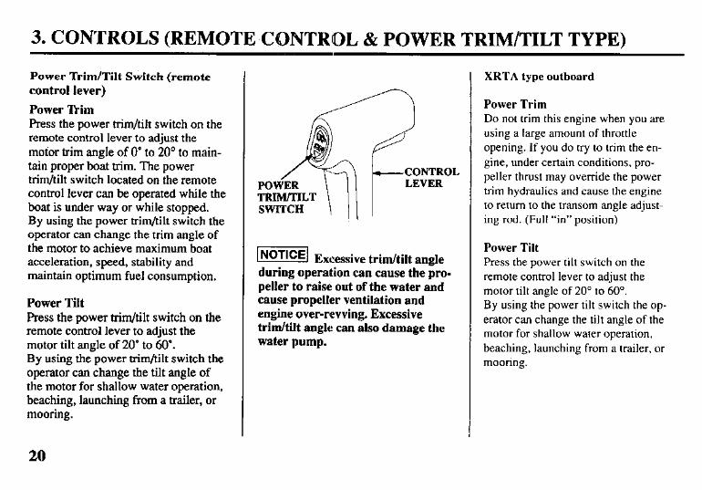
Power ‘Ikim/Tilt Switch (remote control lever)
Power Ikim Press the power him/tilt switch on the remote control lever to adjust the motor trim angle of 0” to 20” to main- tain proper boat trim. The power him/tilt switch located on the remote control lever can be operated while the boat is under way or while stopped. By using the power trim/tilt switch the operator can change the trim angle of the motor to achieve maximum boat acceleration, speed, stability and maintain optimum fuel consumption.
Power Tilt Press the power trim/tilt switch on the remote control lever to adjust the motor tilt angle of 20” to 60”. By using the power trim/tilt switch the operator can change the tilt angle of the motor for shallow water operation, beaching, launching from a trailer, or mooring.
TRIM/TILT SWITCH \ !I I
picziq Excessive trim/tilt angle during operaUion can cause the pro- peller to raise out of the water and cause propeller ventilation and engine over-revving. Excessive trim/tilt angle can also damage the water pump.
XRTA type outboard
Power Trim Do not trim this engine when you are using a large amount of throttle opening. If you do try lo trim the en- gine, under certain conditions, pro- peller thrust may override the power trim hydraulics and cause the engine to return to the transom angle adjust- ing rod. (Full “in” position)
Power Tilt Press the power tilt switch on the remote control lever to adjust the motor tilt angle of 20” to 60”. By using the power tilt switch the op- erator can change the tilt angle of the motor for shallow water operation, beaching, launching from a trailer, or mooring.
20
3. CONTROLS (REMOTE CONTROL & POWER TRIM/TILT TYPE)
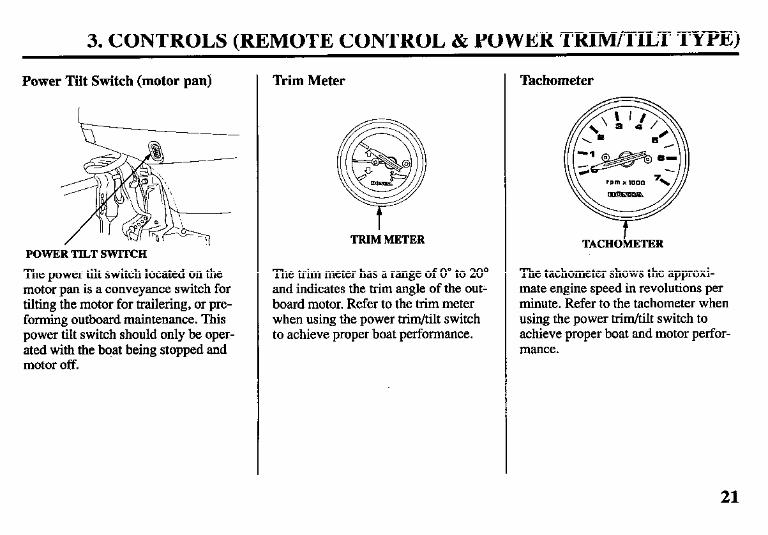
Power Tilt Switch (motor pan)
POWER TILT SWITCH
The power tilt switch located on the motor pan is a conveyance switch for tilting the motor for trailering, or pre- forming outboard maintenance. This power tilt switch should only be oper- ated with the boat being stopped and motor off.
Trim Meter
TRIM METER
The trim meter has a range of 0’ to 20” and indicates the trim angle of the out- board motor. Refer to the trim meter when using the power trim/tilt switch to achieve proper boat performance.
Tachometer
TACHOMETER
The tachometer shows the approxi- mate engine speed in revolutions per minute. Refer to the tachometer when using the power trim/tilt switch to achieve proper boat and motor perfor- mance.
21
3. CONTROLS (REMOTE CONTROL & POWER TRIM/TILT TYPE)
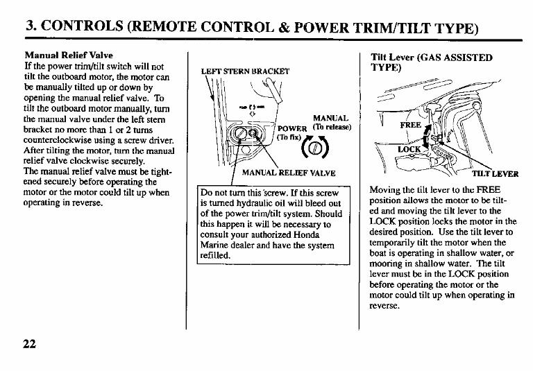
Manual Relief Valve If the power trim/tilt switch will not tilt the outboard motor, the motor can be manually tilted up or down by opening the manual relief valve. To tilt the outboard motor manually, turn the manual valve under the left stem bracket no more than 1 or 2 turns counterclockwise using a screw driver. After tilting the motor, turn the manual relief valve clockwise securely. The manual relief valve must be tight- ened securely before operating the motor or the motor could tilt up when operating in reverse.
LEFT STERN BRACKET
MANUAL POWER m rel=1
I MANUAL-RELIEF VALVE
Do not turn this ‘screw. If this screw is turned hydraulic oil will bleed out of the power trim/tilt system. Should this happen it will be necessary to consult your authorized Honda Marine dealer and have the system refilled.
Tilt Lever (GAS ASSISTED TYPE)
Moving the tilt lever to the FREE position allows the motor to be tilt- ed and moving the tilt lever to the LOCK position locks the motor in the desired position. Use the tilt lever to temporarily tilt the motor when the boat is operating in shallow water, or mooring in shallow water. The tilt lever must be in the LOCK position before operating the motor or the motor could tilt up when operating in reverse.
22
3. CONTROLS & INSTRUMENTS (common)
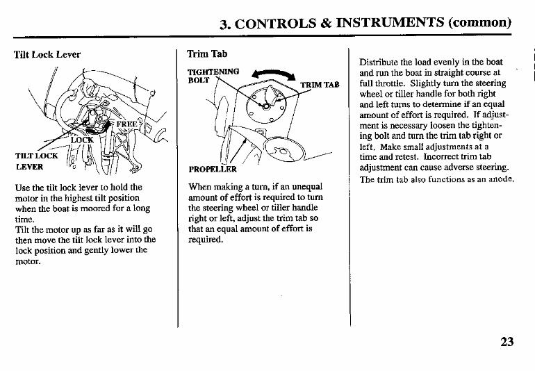
Tilt Lock Lever
Use the tilt lock lever to hold the motor in the highest tilt position when the boat is moored for a long time. Tilt the motor up as far as it will go then move the tilt lock lever into the lock position and gently lower the motor.
Trim Tab
PROPELLER
When making a turn, if an unequal amount of effort is required to turn the steering wheel or tiller handle right or left, adjust the trim tab so that an equal amount of effort is required.
Distribute the load evenly in the boat and run the boat in straight course at full throttle. Slightly turn the steering wheel or tiller handle for both right and left turns to determine if an equal amount of effort is required. If adjust- ment is necessary loosen the tighten- ing bolt and turn the trim tab right or left. Make small adjustments at a time and retest. Incorrect trim tab adjustment can cause adverse steering. The trim tab also functions as an anode.
23
3. CONTROLS & INSTRUMENTS (common)
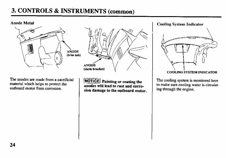
Anode Metal
+I \
The anodes are made from a sacrificial material which helps to protect the outboard motor from corrosion.
ANODi (stem bracket)
Painting or coating the 1 NoTlCq anodes will lead to rust and corro- sion damage to the outboard motor.
Cooling System Indicator
\
COOiING SYSTEM INDICATOR
The cooling system is monitored here to make sure cooling water is circulat- ing through the engine.
24
3. CONTROLS & INSTRUMENTS (ctimmon)
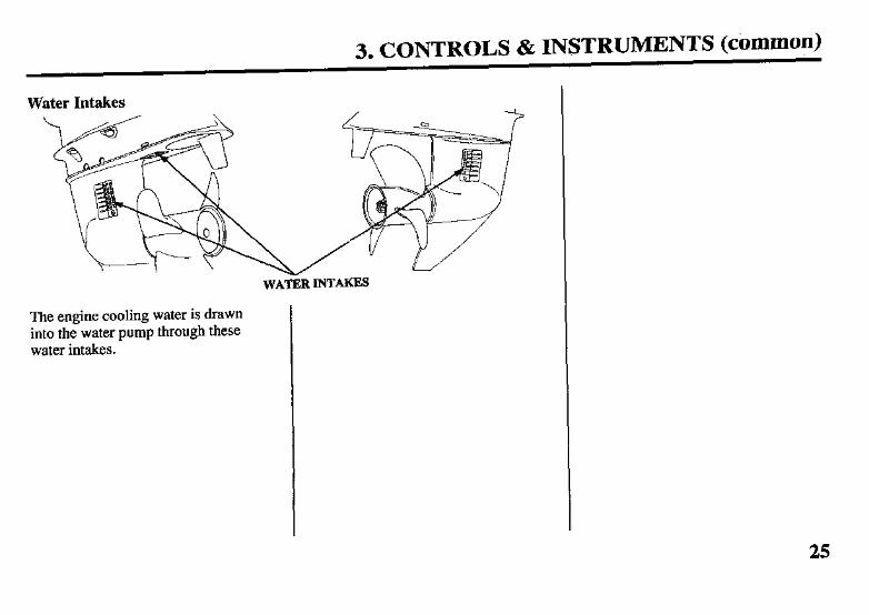
Water Intakes
The engine cooling water is drawn into the water pump through these water intakes.
WATiR INTAKES
25
3. CONTROLS & INSTRUMENTS (common)
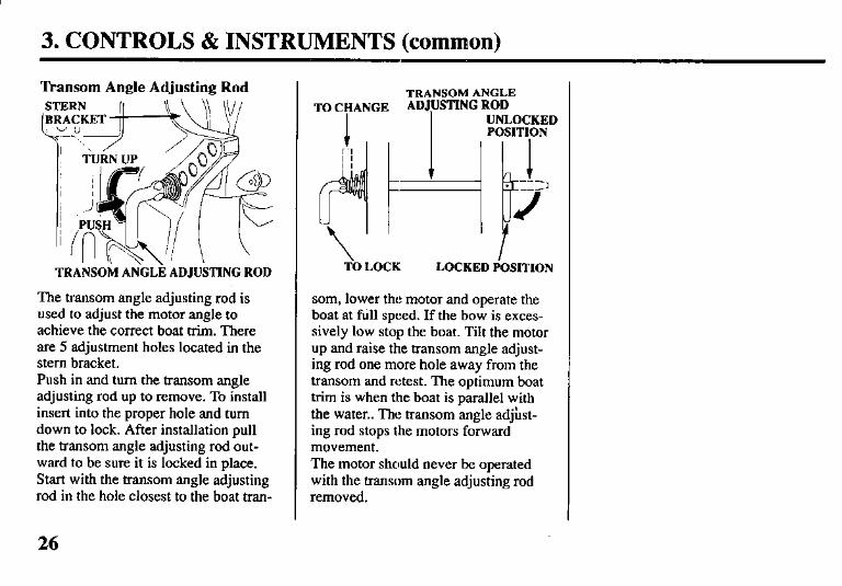
Transom Angle Adjusting Rod
TRANSOM ANGLE ADJUSTING ROD
The transom angle adjusting rod is used to adjust the motor angle to achieve the correct boat him. There are 5 adjustment holes located in the stem bracket. Push in and turn the transom angle adjusting rod up to remove. To install insert into the proper hole and turn down to lock. After installation pull the transom angle adjusting rod out- ward to be sure it is locked in place. Start with the transom angle adjusting rod in the hole closest to the boat tran-
TRANSOM ANGLE TO CHANGE ADJUSTING ROD
I
UNLOCKED POSITION
1 --- .
+=I
--/’
J
TO LOCK LOCKED POSITION
som, lower the motor and operate the boat at full speed. If the bow is exces- sively low stop the boat. Tilt the motor up and raise the transom angle adjust- ing rod one more hole away from the transom and retest. The optimum boat trim is when the boat is parallel with the water.. The transom angle adjust- ing rod stops the motors forward movement. The motor should never be operated with the transom angle adjusting rod removed.
26
3. CONTROLS & INSTRUMENTS (common)
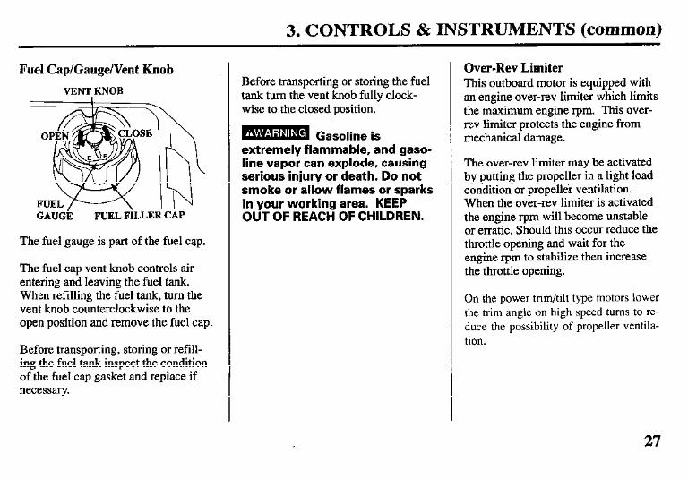
Fuel Cap/Gauge/Vent Knob
VENT KNOB I
GAUGE FUEL FILLER CAP
The fuel gauge is part of the fuel cap.
The fuel cap vent knob controls air entering and leaving the fuel tank. When refilling the fuel tank, turn the vent knob counterclockwise to the open position and remove the fuel cap.
Before transporting, storing or refill- ing the fuel tank inspect the condition of the fuel cap gasket and replace if necessary.
Before transporting or storing the fuel tank turn the vent knob fully clock- wise to the closed position.
B Gasoline is extremely flammable, and gaso- line vapor can explode, causing serious injury or death. Do not smoke or allow flames or sparks in your working area. KEEP OUT OF REACH OF CHILDREN.
Over-Rev Limiter This outboard motor is equipped with an engine over-rev limiter which limits the maximum engine r-pm. This over- rev limiter protects the engine from mechanical damage.
The over-rev limiter may be activated by putting the propeller in a light load condition or propeller ventilation. When the over-rev limiter is activated the engine rpm will become unstable or erratic. Should this occur reduce the throttle opening and wait for the engine rpm to stabilize then increase the throttle opening.
On the power trim/tilt type motors lower the trim angle on high speed turns to re- duce the possibility of propeller ventila- tion.
27
4. PRE-OPERATION CHECKS
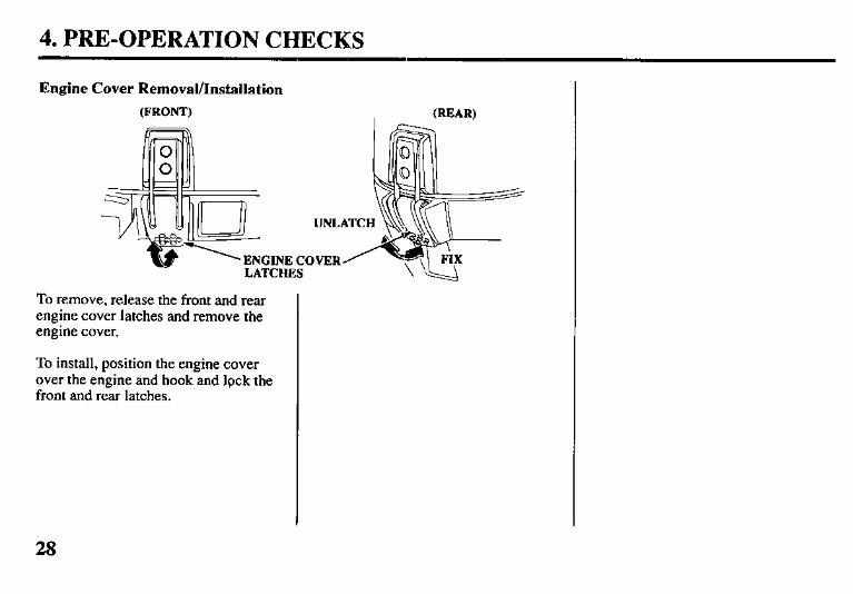
Engine Cover Removal/Installation
(FRONT) (REAR)
ENGINE COVER
To remove, release the front and rear engine cover latches and remove the engine cover.
To install, position the engine cover over the engine and hook and lpck the front and rear latches.
28
4. PRE-OPERATION CHECKS
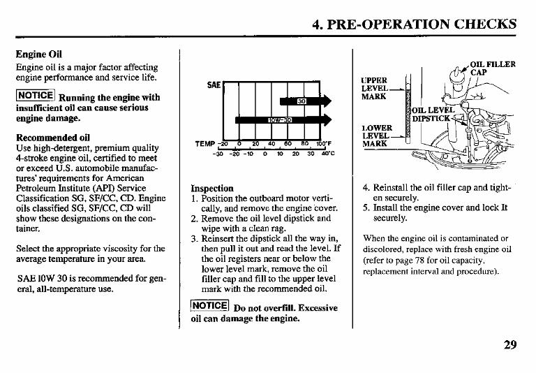
Engine Oil Engine oil is a major factor affecting engine performance and service life.
w Running the engine with insufficient oil can cause serious engine damage.
Recommended oil Use high-detergent, premium quality Cstroke engine oil, certified to meet or exceed U.S. automobile manufac- tures’ requirements for American Petroleum Institute (API) Service Classification SG, SF/CC, CD. Engine oils classified SG, SF/CC, CD will show these designations on the con- tainer.
Select the appropriate viscosity for the average temperature in your area.
SAE 1OW 30 is recommended for gen- eral, all-temperature use.
SAf
TEMP ; -3
20 40 60
-20 -10 0 10 20 30 40%
Inspection 1. Position the outboard motor verti-
cally, and remove the engine cover. 2. Remove the oil level dipstick and
wipe with a clean rag. 3. Reinsert the dipstick all the way in,
then pull it out and read the level. If the oil registers near or below the lower level mark, remove the oil filler cap and fill to the upper level mark with the recommended oil.
m Do not overfill. Excessive oil can damage the engine.
4. Reinstall the oil filler cap and tight- en securely.
5. Install the engine cover and lock It securely.
When the engine oil is contaminated or discolored, replace with fresh engine oil (refer to page 78 for oil capacity, replacement interval and procedure).
29
4. PRE-OPERATION CHECKS
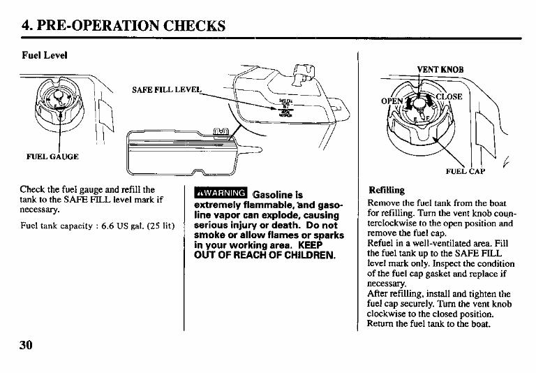
Check the fuel gauge and refill the tank to the SAFE FILL level mark if necessary.
Fuel tank capacity : 6.6 US gal. (25 lit)
B Gasoline is extremely flammable, ‘and gaso- line vapor can explode, causing serious injury or death. Do not smoke or allow flames or sparks in your working area. KEEP OUT OF REACH OF CHILDREN.
VENT KNOB
FUEL CAP
Refilling Remove the fuel tank from the boat for refilling. Turn the vent knob coun- terclockwise to the open position and remove the fuel cap. Refuel in a well-ventilated area. Fill the fuel tank up to the SAFE FILL level mark only. Inspect the condition of the fuel cap gasket and replace if necessary. After refilling, install and tighten the fuel cap securely. Turn the vent knob clockwise to the closed position. Return the fuel tank to the boat.
30
4. PRE-OPERATION CHECKS
Recommended fuel Your engine is designed to use any gasoline that has a pump octane num- ber ( v) of 86 or higher, or that has a research octane number of 91 or higher. Gasoline pumps at service sta- tion normally display the pump octane number. We recommend that you use unleaded fuel because it produces fewer engine and spark plug deposits and extends the life of exhaust system components.
Never use stale or contaminated gaso- line or an oil/gasoline mixture. Avoid getting dirt, dust or water in the fuel tank. Use of a lower octane gasoline can cause persistent “pinging” or heavy “spark knock” (a metallic rap- ping noise) which, if severe, can lead to engine damage.
@!!@ If “spark knock” or “pinging” occurs at a steady engine speed under normal load, change brands of gasoline. If spark knock or pinging persists, consult your
authorized Honda dealer. Failure to do.so is considered misuse, and damage caused by misuse is not cov- ered by Honda’s Limited Warranty.
Occasionally you may experience light spark knock while operating under heavy loads. This is no cause for concern, it simply means your engine is operating efficiently.
GASOLINES CONTAINING ALCOHOL
If you decide to use a gasoline con- taining alcohol (gasohol), be sure its octane rating is at least as high as that recommended by Honda. There are two types of “gasohol”: one containing ethanol, and the other containing methanol. Do not use gasohol that contains more than 10% ethanol. Do not use gasoline containing methanol (methyl or wood alcohol) that does not also contain cosolvents and corrosion inhibitors for methanol. Never use
gasoline containing more than-5% methanol, even if it has cosolvents and corrosion inhibitors.
Fuel system damage or engine perform- ance problems resulting from the use of fuels that contain alcohol is not covered under the warranty. Honda cannot endorse the use of fuels containing methanol since evidence of their suitability is as yet incomplete. Before buying fuel from an unfamiliar station, try to find out if the fuel contains alcohol. If it does, confirm the type and percentage of alcohol used. If you notice any undesirable operating symptoms while using a gasoline that contains alcohol, or one that you think contains alcohol, switch to a gasoline that you know does not contain alcohol.
31
4. PRE-OPERATION CHECKS
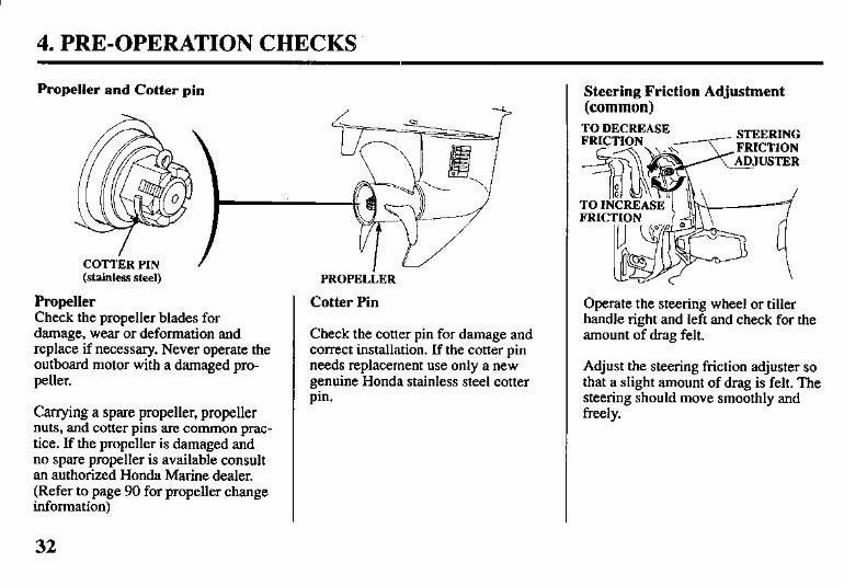
Propeller and Cotter pin
COTTi3.a PIN / (stainless steel)
Propeller Check the propeller blades for damage, wear or deformation and replace if necessary. Never operate the outboard motor with a damaged pro- peller.
Carrying a spare propeller, propeller nuts, and cotter pins are common prac- tice. If the propeller is damaged and no spare propeller is available consult an authorized Honda Marine dealer. (Refer to page 90 for propeller change information)
32
I - PROPELLER
Cotter Pin
Check the cotter pin for damage and correct installation. If the cotter pin needs replacement use only a new genuine Honda stainless steel cotter pin.
Steering Friction Adjustment (common) II r0 DECREASE
--------- G-Jpz~~
\ /
Operate the steering wheel or tiller handle right and left and check for the amount of drag felt.
Adjust the steering friction adjuster so that a slight amount of drag is felt. The steering should move smoothly and freely.
4. PRE-OPERATION CHECKS
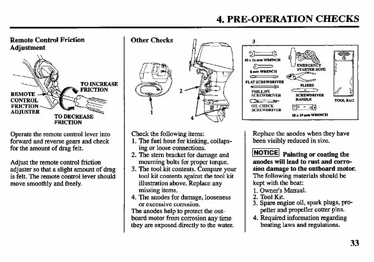
Remote Control Friction Adjustment
TO INCREASE
TO DECREASE FRICTION
Operate the remote control lever into forward and reverse gears and check for the amount of drag felt.
Adjust the remote control friction adjuster so that a slight amount of drag is felt. The remote control lever should move smoothly and freely.
Check the following items: 1. The fuel hose for kinking, collaps-
ing or loose connections. 2. The stem bracket for damage and
mounting bolts for proper torque. 3. The tool kit contents. Compare your
tool kit contents against the tool kit illustration above. Replace any missing items.
4. The anodes for damage, looseness or excessive corrosion.
The anodes help to protect the out- board motor from corrosion any time they are exposed directly to the water.
3 G 10 x 17. mnt WRENCH
Other Checks
(I mm WRENCH r J 9
FLAT SCREWDRIVER
PHILLIPS - sCREWDRIVER
c_s C=TT
OIL CHECK SCREWDRIVER
STARTER ROPE
PLIERS c 13 ,
SCREWDRIVER HANDLE
Bg+J
18 x 19 mm WRENCH
Replace the anodes when they have been visibly reduced in size.
m Painting or coating the anodes will lead to rust and corro- sion damage to the outboard motor. The following materials should be kept with the boat: 1. Owner’s Manual. 2. Tool Kit. 3. Spare engine oil, spark plugs, pro-
peller and propeller cotter pins. 4. Required information regarding
boating laws and regulations.
33
5. STARTING THE ENGINE
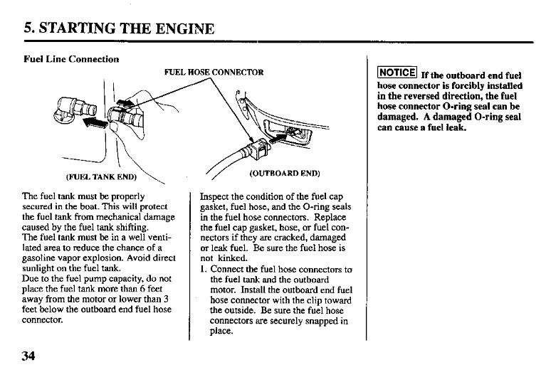
Fuel Line Connection FUEL HOSE CONNECTOR
(OUTBOARD END) (FUEL TANK END) \
The fuel tank must be properly secured in the boat. This will protect the fuel tank from mechanical damage caused by the fuel tank shifting. The fuel tank must be in a well venti- lated area to reduce the chance of a gasoline vapor explosion. Avoid direct sunlight on the fuel tank. Due to the fuel pump capacity, do not place the fuel tank more than 6 feet away from the motor or lower than 3 feet below the outboard end fuel hose connector.
Inspect the condition of the fuel cap gasket, fuel hose, and the O-ring seals in the fuel hose connectors. Replace the fuel cap gasket, hose, or fuel con- nectors if they are cracked, damaged or leak fuel. Be sure the fuel hose is not kinked. 1. Connect the fuel hose connectors to
the fuel tank and the outboard motor. Install the outboard end fuel hose connector with the clip toward the outside. Be sure the fuel hose connectors are securely snapped in place.
w If the outboard end fuel hose connector is forcibly installed in the reversed direction, the fuel hose connector O-ring seal can be damaged. A damaged O-ring seal can cause a fuel leak.
34
5: STARTING THE ENGINE
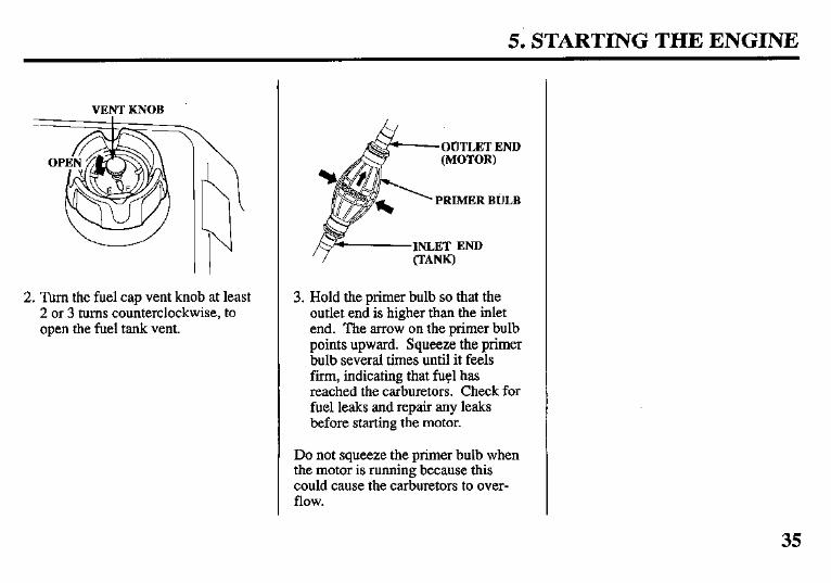
VENT KNOB
2. Turn the fuel cap vent knob at least 2 or 3 turns counterclockwise, to open the fuel tank vent.
OUTLET END
3. Hold the primer bulb so that the outlet end is higher than the inlet end. The arrow on the primer bulb points upward. Squeeze the primer bulb several times until it feels firm, indicating that fuel has reached the carburetors. Check for fuel leaks and repair any leaks before starting the motor.
Do not squeeze the primer bulb when the motor is running because this could cause the carburetors to over- flow.
35
5. STARTING THE ENGINE (TILLER HANDLE TYPE)
\ ENGINE STOP SWITCH
EilERGtiCY STOP f;;;$;;;;psTop SWITCH LANYARD
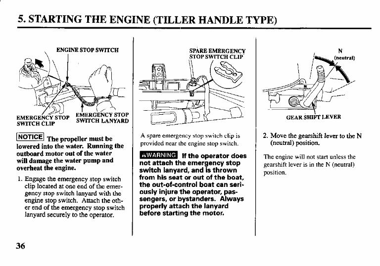
1 NOTICE/ The propeller must be lowered into the water. Running the outboard motor out of the water will damage the water pump and overheat the engine.
1. Engage the emergency stop switch clip located at one end of the emer- gency stop switch lanyard with the engine stop switch. Attach the oth- er end of the emergency stop switch lanyard securely to the operator.
SPARE EMERGENCY STOP SWITCH CLIP-
A spare emergency stop switch clip is provided near the engine stop switch.
m lf the operator does not attach the emergency stop switch lanyard, and is thrown from his seat or out of the boat, the out-of-control boat can seri- ously injure the operator, pas- sengers, or bystanders. Always properly attach the lanyard before starting the motor.
GEAR SHIIh LEVER
2. Move the gearshift lever to the N (neutral) position.
The engine will not start unless the gearshift lever is in the N (neutral) position.
36
5. STARTING THE ENGINE (TILLER HANDLE TYPE)
THROTIiE GRIP
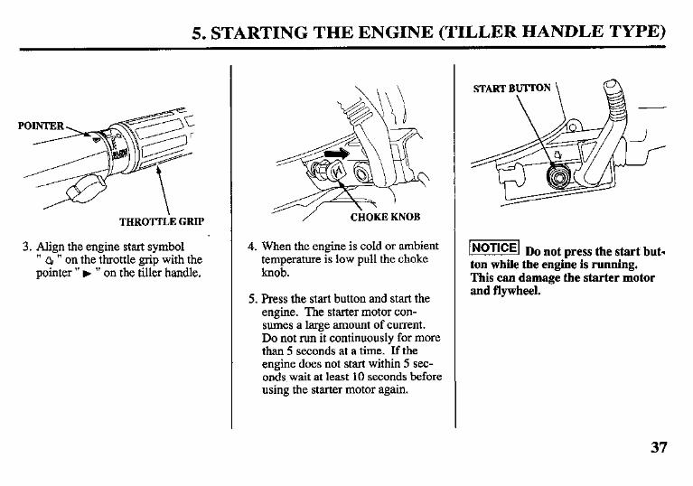
3. Align the engine start symbol ” QI ” on the throttle grip with the pointer ” F ” on the tiller handle.
4. When the engine is cold or ambient temperature is low pull the choke knob.
5. Press the start button and start the engine. The starter motor con- sumes a large amount of current. Do not run it continuously for more than 5 seconds at a time. If the engine does not start within 5 sec- onds, wait at least 10 seconds before using the starter motor again.
/iGTiiq Do not press the start but- ton while the engine is running. This can damage the starter motor and flywheel.
37
5. STARTING THE ENGINE (TILLER HANDLE TYPE)
CHOltE K\NOB THRO’ITLE GRIP
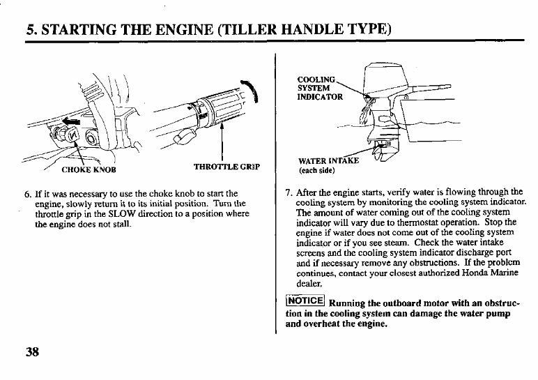
6. If it was necessary to use the choke knob to start the engine, slowly return it to its initial position. Turn the throttle grip in the SLOW direction to a position where the engine does not stall.
WATER INTAG w (each side)
7. After the engine starts, verify water is flowing through the cooling system by monitoring the cooling system indicator. The amount of water coming out of the cooling system indicator will vary due to thermostat operation. Stop the engine if water does not come out of the cooling system indicator or if you see steam. Check the water intake screens and the cooling system indicator discharge port and if necessary remove any obstructions. If the problem continues, contact your closest authorized Honda Marine dealer.
INoTicE] R unning the outboard motor with an obstruc- tion in the coolingsystem can damage the water pump and overheat the engine.
38
5. STARTING THE ENGINE (TILLER HANDLE TYPE)
OIL PRESSURE ~IyIcATORLIyHT
\ J
Bjfl &, -
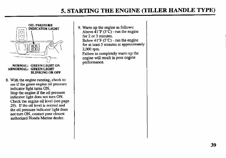
NORMAL: GREEN LIGHT ON ABNORMAL: GREEN LIGHT
BLINKING OR OFF
8. With the engine running, check to see if the green engine oil pressure indicator light turns ON. Stop the engine if the oil pressure indicator light does not mm ON. Check the engine oil level (see page 29). If the oil level is normal and the oil pressure indicator light does not turn ON, contact your closest authorized Honda Marine dealer.
9. Warm up the engine as follows: Above 41°F (5°C) - run the engine for 2 or 3 minutes. Below 41°F (YC) - run the engine for at least 5 minutes at approximately 2,000 rpm. Failure to completely warm up the engine will result in poor engine performance.
39
5. STARTING THE ENGINE (REMQTE CONTROL TYPE)
EMERGENCY
EhERGENCY S’i’OP SWITCH CLIP
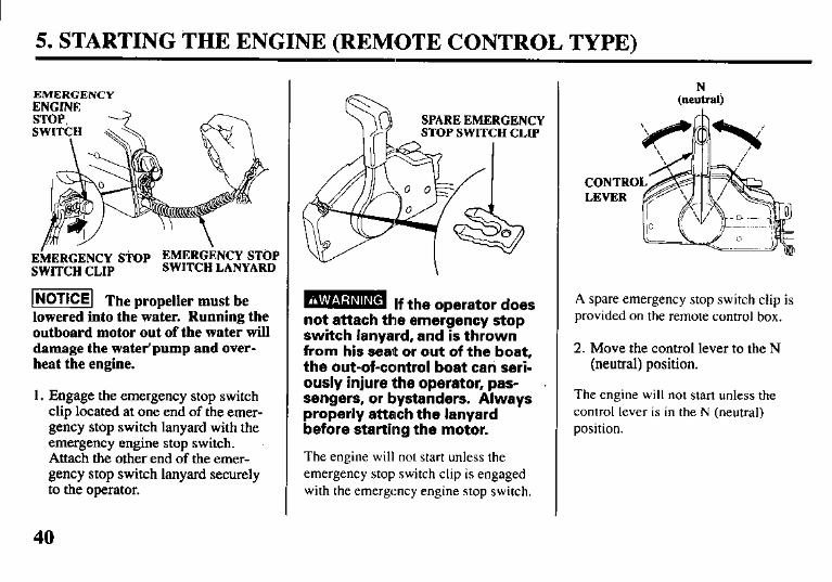
I NOTICEI The propeller must be lowered into the water. Running the outboard motor out of the water will damage the water’pump and over- heat the engine.
1. Engage the emergency stop switch clip located at one end of the emer- gency stop switch lanyard with the emergency engine stop switch. Attach the other end of the emer- gency stop switch lanyard securely to the operator.
- If the operator does not attach the emergency stop switch lanyard, and is thrown from his seaQ or out of the boat, the out-of-control boat can seri- ously injure the operator, pas- sengers, or bystanders. Always properly attach the lanyard before starting the motor.
The engine will not start unless the emergency stop switch clip is engaged with the emergency engine stop switch.
N (neutralj
A spare emergency stop switch clip is provided on the remote control box.
2. Move the control lever to the N (neutral) position.
The engine will not start unless the control lever is in the N (neutral) position.
40
5. STARTING THE ENGINE (REMOTE CONTROL TYPE)
XIMUM FAST
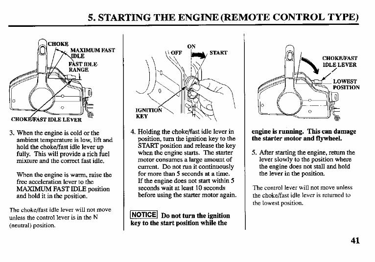
3. When the engine is cold or the ambient temperature is low, lift and hold the choke/fast idle lever up fully. This will provide a rich fuel mixture and the correct fast idle.
When the engine is warm, raise the free acceleration lever to the MAXIMUM FAST IDLE position and hold it in the position.
The choke/fast idle lever will not move unless the control lever is in the N (neutral) position.
ON
4. Holding the choke/fast idle lever in position, turn the ignition key to the START position and release the key when the engine starts. The starter motor consumes a large amount of current. Do not run it continuously for more than 5 seconds at a time. If the engine does not start within 5 seconds wait at least 10 seconds before using the starter motor again.
m Do not turn the ignition key to the start position while the
CHOKE/FAST IDLE LEVER
engine is running. This can damage the starter motor and flywheel.
5. After starting the engine, return the lever slowly to the position where the engine does not stall and hold the lever in the position.
The control lever will not move unless the choke/fast idle lever is returned to the lowest position.
41
I 5. STARTING THE ENGINE (REMOTE CONTROL TYPE)
COOLING SYSTEM e
INDICATOR
WATER INTAKE (each side)
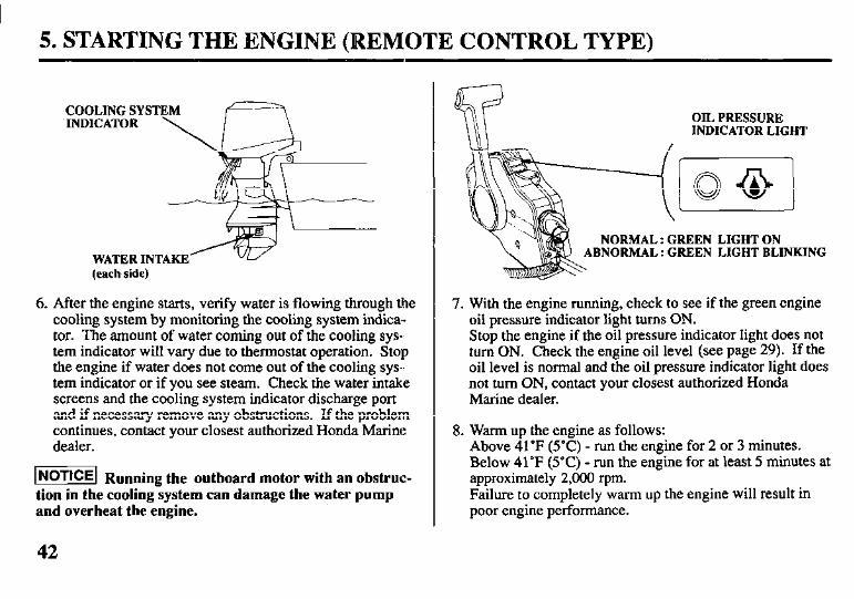
6. After the engine starts, verify water is flowing through the cooling system by monitoring the cooling system indica- tor. The amount of water coming out of the cooling sys-, tern indicator will vary due to thermostat operation. Stop the engine if water does not come out of the cooling sys- tem indicator or if you see steam. Check the water intake screens and the cooling system indicator discharge port and if necessary remove any obstructions. If the problem continues, contact your closest authorized Honda Marine dealer.
m Running the outboard motor with an obstruc- tion in the cooling system can damage the water pump and overheat the engine.
OIL PRESSURE INDICATOR LIGHT
NORMAL : GREEN LIGHT ON BNORMAL : GREEN LIGHT BLINKING
7. With the engine running, check to see if the green engine oil pressure indicator light turns ON. Stop the engine if the oil pressure indicator light does not turn ON. Check the engine oil level (see page 29). If the oil level is normal and the oil pressure indicator light does not turn ON, contact your closest authorized Honda Marine dealer.
8. Warm up the engine as follows: Above 41°F (5°C) - run the engine for 2 or 3 minutes. Below 41°F (YC) - run the engine for at least 5 minutes at approximately 2,000 rpm. Failure to completely warm up the engine will result in poor engine performance.
42
5. STARTING THE ENGINE
Emergency Starting (FRONT) (REAR)
FIXINCLEVER
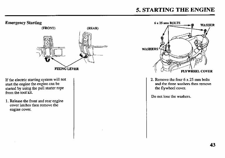
If the electric starting system will not start the engine the engine can be started by using the pull starter rope from the tool kit.
1. Release the front and rear engine cover latches then remove the engine cover.
2. Remove the four 6 x 25 mm bolts and the three washers then remove the flywheel cover.
Do not lose the washers.
43
5. STARTING THE ENGINE
SHIF? LEVER
(TILLER HANDLE TYPE)
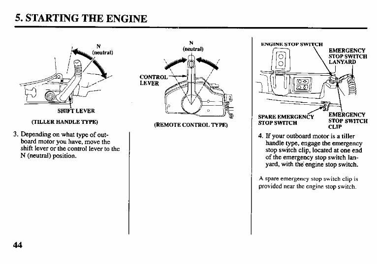
3. Depending on what type of out- board motor you have, move the shift lever or the control lever to the N (neutral) position.
(REMOTE CONTROL TYPE)
ENGINE STOP SWITCH EMERGENCY STOP SWITCH
SPARE EMERGEN STOP SWITCH
CLIP
4. If your outboard motor is a tiller handle type, engage the emergency stop switch clip, located at one end of the emergency stop switch lan- yard, with the’engine stop switch.
A spare emergency stop switch clip is provided near the engine stop switch.
44
5. STARTING THE ENGINE
EMERGENCY sTOPswITCH CLIP'
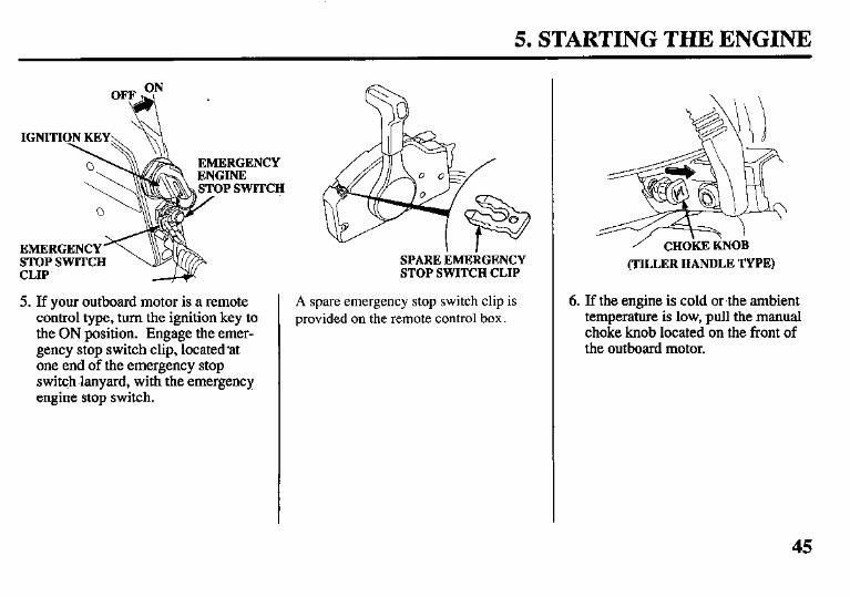
5. If your outboard motor is a remote control type, turn the ignition key to the ON position. Engage the emer- gency stop switch clip, located*at one end of the emergency stop switch .lanyard, with the emergency engine stop switch.
SPARE~MEKGENCY STOPSWITCHCLIP
A spare emergency stop switch clip is provided on the remote control box.
/ CHOkEIiNOB (TILLERHANDLETYPE)
6. If the engine is cold or the ambient temperature is low, pull the manual choke knob located on the front of the outboard motor.
45
5. STARTING THE ENGINE
{REMOTE CONTROL TYPE)
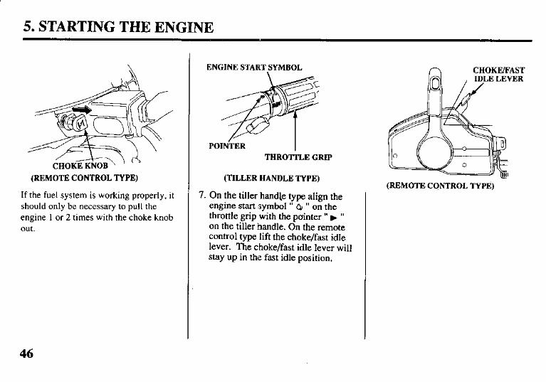
If the fuel system is working properly, it should only be necessary to pull the engine 1 or 2 times with the choke knob out.
ENGINE START,SYMBOL
POIN-TER I THROTTLE GRIP
(TILLER HANDLE TYPE)
7. On the tiller handle type align the engine start symbol ” QI ” on the throttle grip with the puinter ” ) ” on the tiller handle. On the remote control type lift the choke/fast idle lever. The choke/fast idle lever will stay up in the fast idle position.
n CHOKFJFAST
(REMOTE CONTROL TYPE)
46
5. STARTING THE ENGINE
FLYWHEEL EMERGENCY
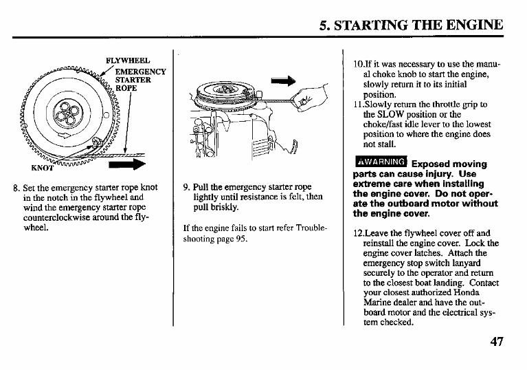
8. Set the emergency starter rope knot in the notch in the flywheel and wind the emergency starter rope counterclockwise around the fly- wheel.
9. Pull the emergency starter rope lightly until resistance is felt, then pull briskly.
If the engine fails to start refer Trouble- shooting page 95.
lO.If it was necessary to use the manu- al choke knob to start the engine, slowly return it to its initial position.
11 .Slowly return the throttle grip to the SLOW position or the choke/fast idle lever to the lowest position to where the engine does not stall.
parts can caussinjury. Use extreme care when installing the engine cover. Do not oper- ate the outboard motor without the engine cover.
12.Leave the flywheel cover off and reinstall the engine cover. Lock the engine cover latches. Attach the emergency stop switch lanyard securely to the operator and return to the closest boat landing. Contact your closest authorized Honda Marine dealer and have the out- board motor and the electrical sys- tem checked.
47
5. STARTING THE ENGINE
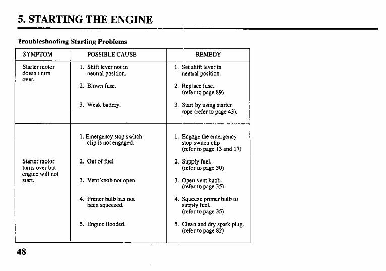
‘Ikoubleshooting Starting Problems
SYMPTOM
Starter motor doesn’t turn over.
Starter motor turns over but engine will not Start.
POSSIBLE CAUSE
1. Shift lever not in neutral position.
2. Blown fuse.
3. Weak battery.
1. Emergency stop switch clip is not engaged.
2. Out of fuel
3. Vent knob not open.
4. Primer bulb has not been squeezed.
5. Engine flooded.
REMEDY
1. !jet shift lever in neutral position.
2. Replace fuse. (refer to page 89)
3. Start by using starter rope (refer to page 43).
1. Engage the emergency stop switch clip (refer to page 13 and 17)
2. Supply fuel. (refer to page 30)
3. Open vent knob. (refer to page 35)
4. Squeeze primer bulb to supply fuel. (refer to page 35)
5. Clean and dry spark plug. (refer to page 82)
6. OPERATION
Break-in Procedure Break-in period 10 hours
Break-in operation allows the moving parts to wear-in evenly and thus ensures proper performance and longer outboard motor life.
Break-in your new outboard motor as follows:
First 15 minutes: Run the outboard motor at trolling speed. Use the minimum amount of throttle opening necessary to operate the boat at a safe trolling speed.
Next 45 minutes: Run the outboard motor up to a maximum of 2,000 to 3,000 rpm or 10% to 30% throttle opening.
Next 60 minutes: Run the outboard motor up to maxi- mum of 4,000 to 5,000 rpm or 50% to 80% throttle opening. Short
bursts of full throttle are acceptable but do not operate the motor contin- uously at full throttle.
Next 8 hours: Avoid continuous full throttle oper- ation (100% throttle opening). Do not run the outboard motor at full throttle for more than 5 minutes at a time.
For boats that plane easily, bring the boat up on plane then reduce the throttle opening to the specified break-in settings called out above.
49
6. OPERATION (TILLER HANI9LE’ TYPE)
I POIN’j-ER L FAST
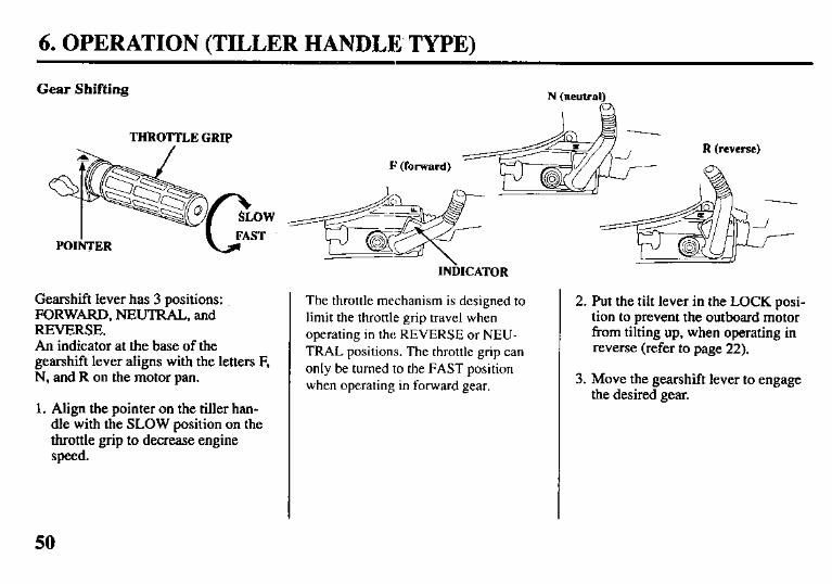
Gearshift lever has 3 positions: FORWARD, NEUTRAL, and REVERSE. An indicator at the base of the gearshift lever aligns with the letters F, N, and R on the motor pan.
1. Align the pointer on the tiller han- dle with the SLOW position on the throttle grip to decrease engine speed.
N (neutral) 63
R (reverse)
INhICATOR
The throttle mechanism is designed to limit the throttle grip travel when operating in the REVERSE or NEU- TRAL positions. The throttle grip can only be turned to the FAST position when operating in forward gear.
2. Put the tilt lever in the LOCK posi- tion to prevent the outboard motor from tilting up, when operating in reverse (refer to page 22).
3. Move the gearshift lever to engage the desired gear.
50
6. OPERATION (TILLER HANDLE TYPE)
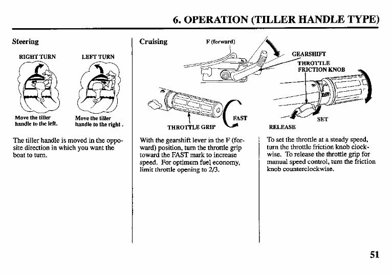
Steering
RIGHT TURN LEFT TURN
Move the tiller handle to the left.
Move the tiller handle to the right.
The tiller handle is moved in the oppo- site direction in which you want the boat to turn.
Cruising
THROTkLE GRIP RELEASE
With the gearshift lever in the F (for- To set the throttle at a steady speed, ward) position, turn the throttle grip turn the throttle friction knob clock- toward the FAST mark to increase wise. To release the throttle grip for speed. For optimum fuel economy, manual speed control, turn the friction limit throttle opening to 2/3. knob counterclockwise.
51
6. OPERATION (REMOTE CONTROL TYPE)
Gear Shifting
1 ,I PULL UP
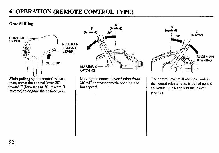
While pulling up the neutral release lever, move the control lever 30 toward F (forward) or 30” toward R (reverse) to engage the desired gear.
Moving the control lever further from 30” will increase throttle opening and boat speed.
N (neutral)
I 30” R
(reverse)
The control lever will not move unless the neutral release lever is pulled up and choke/fast idle lever is in the lowest position.
52
6. OPERATION (REMOTE CONTROL TYPE)
Cruising
POWER TRIM/TILT SWITCH
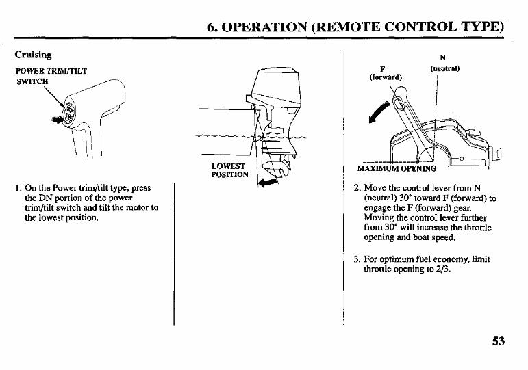
1. On the Power trim/tilt type, press the DN portion of the power trim/tilt switch and tilt the motor to the lowest position.
N (neutral)
I
2. Move the control lever from N (neutral) 30” toward F (forward) to engage the F (forward) gear. Moving the control lever further from 30” will increase the throttle opening and boat speed.
3. For optimum fuel economy, limit throttle opening to 2/3.
53
6. OPERATION (GAS ASSISTED TILT TYPE)
Tilt Lever
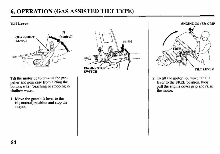
Tilt the motor up to prevent the pro- peller and gear case from hitting the bottom when beaching or stopping in shallow water.
1. Move the gearshift lever to the N ( neutral) position and stop the engine.
54
\ i \ \d PUSH
SWITCH
ENGINE COVER GRIP
TILT LEVER
2. To tilt the motor up, move the tilt lever to the FREE position, then pull the engine cover grip and raise the motor.
6. OPERATION (GAS ASSISTED TILT TYPE)
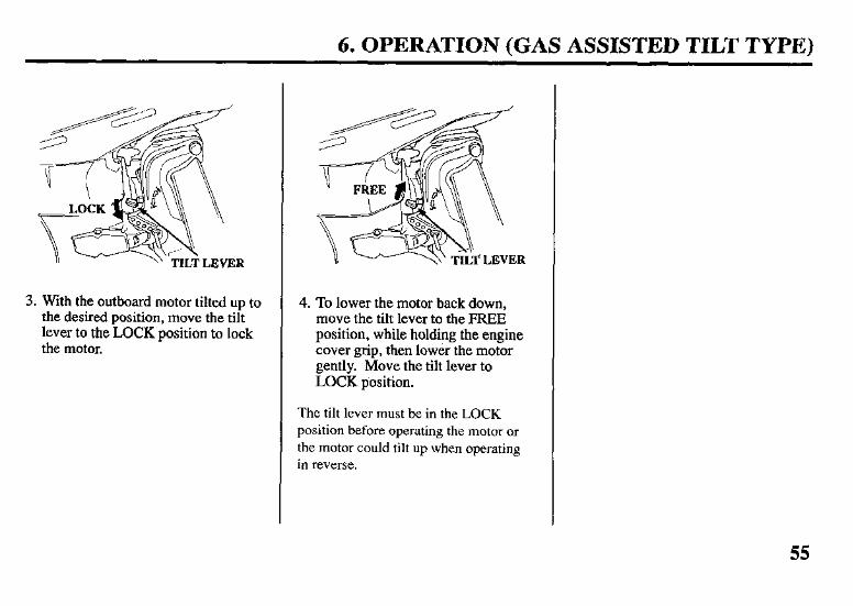
3. With the outboard motor tilted up to the desired position, move the tilt lever to the LOCK position to lock the motor.
4. To lower the motor back down, move the tilt lever to the FREE position, while holding the engine cover grip, then lower the motor gently. Move the tilt lever to LOCK position.
The tilt lever must be in the LOCK position before operating the motor or the motor could tilt up when operating in reverse.
55
6. OPERATION (GAS ASSISTED SYSTEM)
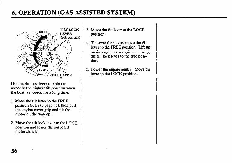
TILTLOCK
Use the tilt lock lever to hold the motor in the highest tilt position when the boat is moored for a long time.
1. Move the tilt lever to the FREE position (refer to page 55), then pull the engine cover grip and tilt the motor all the way up.
2. Move the tilt lock lever to the LOCK position and lower the outboard motor slowly.
3. Move the tilt lever to the LOCK position.
4. To lower the motor, move the tilt lever to the FREE position. Lift up on the engine cover grip and swing the tilt lock lever to the free posi- tion.
5. Lower the engine gently. Move the lever to the LOCK position.
56
6. OPERATION (POWER TRIM/TILT TYPE)
XRTA type outboard (refer to page 20)
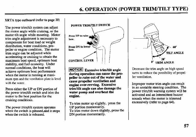
The power trim/tilt system can adjust the motor angle while cruising, or the motor tilt angle while mooring. Motor trim angle adjustment is necessary to compensate for boat load or weight distribution, water conditions, pro- peller or engine condition. The motor trim angle can be adjusted while accelerating or cruising to obtain the maximum boat speed, optimum boat stability, and fuel economy. Under normal conditions, the boat will achieve optimum boat performance when the motor is running at maxi- mum rpm and the ventilation plate is level with the water.
Press either the UP or DN portion of the power trim/tilt switch and trim the motor to the best position for the cruising conditions.
The power trim/tilt system operates when the switch is pressed,and it stops when the switch is released.
POWER TRIM/TILT SWITCH
Press UP to raise bow.
Press DN to lower bow.
CONTROL LEVER
I&!@@ Excessive trim/tilt angle during operation can cause the pro- peller to raise out of the water and cause propeller ventilation and engine over-rewing. Excessive trim/tilt angle can also damage the water pump and overheat the engine.
To trim motor up slightly, press the UP portion momentarily. To trim motor down slightly, press the DN portion momentarily.
60”
ANGLE
I ’ 20 0” TRIM ANGLE
Decrease the trim angle on high speed turns to reduce the possibility of propel- ler ventilation.
Improper motor him angle can result in an unstable steering condition. The power trim/tilt warning system will be activated and an intermittent buzzer sounds when the motor is trimmed excessively (refer to page 64).
57
6. OPERATION (POWER TRIM/TILT TYPE)
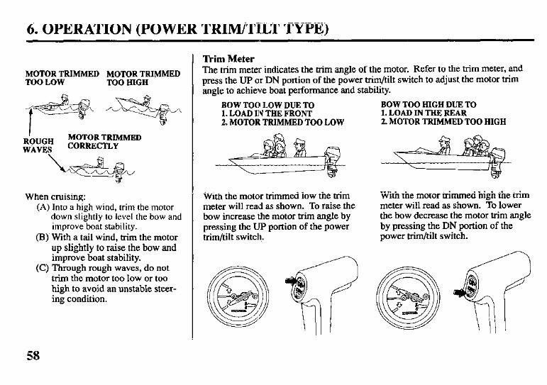
MOTOR TRIMMED MOTOR TRIMMED TOO LOW TOO HIGH
R’OUGH MOTOR TRIMMED
WkVi?s CORRECTLY
When cruising: (A) Into a high wind, trim the motor
down slightly to level the bow and improve boat stability.
(B) With a tail wind, trim the motor up slightly to raise the bow and improve boat stability.
(C) Through rough waves, do not trim the motor too low or too high to avoid an unstable steer- ing condition.
Trim Meter The trim meter indicates the trim angle of the motor. Refer to the trim meter, and press the UP or DN portion of the power trim/tilt switch to adjust, the motor trim angle to achieve boat performance and stability.
BOW TOO LOW DUE TO I. LOAD IN THE FRONT 2. MOTOR TRIMMED TOO LOW
BOW TOO HIGH DUE TO I. LOAD IN THE REAR 2. MOTOR TRIMMED TOO HIGH
With the motor trimmed low the trim meter will read as shown. To raise the bow increase the motor trim angle by pressing the Up portion of the power trim/tilt switch.
With the motor trimmed high the trim meter will read as shown. To lower the bow decrease the motor trim angle by pressing the DN portion of the power trim/tilt switch.
58
6. OPERATION (POWER TRIM/TILT TYPE)
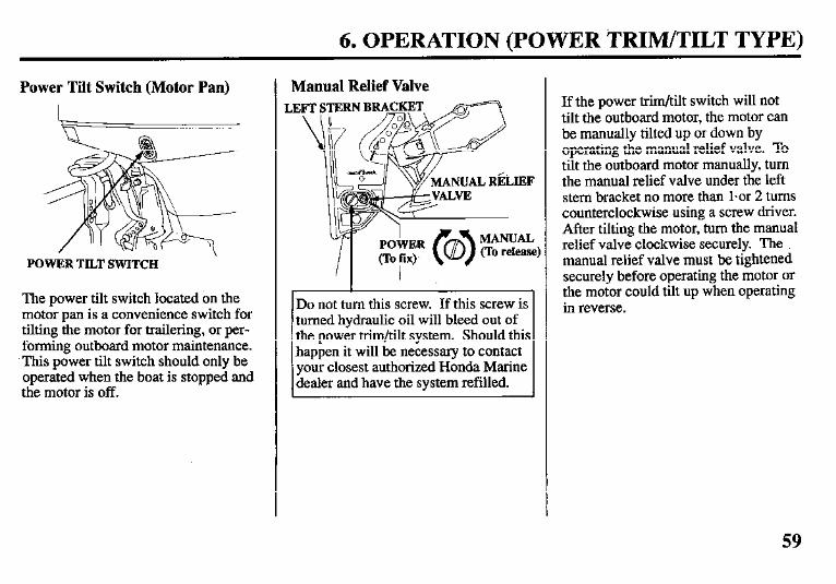
Power Tilt Switch (Motor Pan)
POWER TILT SWITCH
The power tilt switch located on the motor pan is a convenience switch for tilting the motor for trailering, or per- forming outboard motor maintenance. This power tilt switch should only be operated when the boat is stopped and the motor is off.
Manual Relief Valve LE
Do not turn this screw. If this screw is turned hydraulic oil will bleed out of the power trim/tilt system. Should this happen it will be necessary to contact your closest authorized Honda Marine dealer and have the system refilled.
If the power trim/tilt switch will not tilt the outboard motor, the motor can be manually tilted up or down by operating the manual relief valve. To tilt the outboard motor manually, turn the manual relief valve under the left stem bracket no more than lsor 2 turns counterclockwise using a screw driver. After tilting the motor, turn the manual relief valve clockwise securely. The manual relief valve must be tightened securely before operating the motor or the motor could tilt up when operating in reverse.
59
6. OPERATION (POWER TRIM/TILT TYPE)
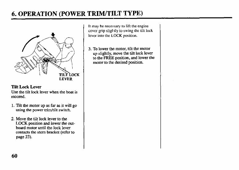
LEVER
Tilt Lock Lever Use the tilt lock lever when the boat is moored.
1. Tilt the motor up as far as it will go using the power trim/tilt switch.
2. Move the tihlock lever to the LOCK position and lower the out- board motor until the lock lever contacts the stem bracket (refer to page 23).
It may be necessary to lift the engine cover grip slightly to swing the tilt lock lever into the LOCK position.
3. To lower the motor, tilt the motor up slightly, move the tilt lock lever to the FREE position, and lower the motor to the desired position.
60
6. OPERATION
Trim Tab Adjustment
TIGHTENING B
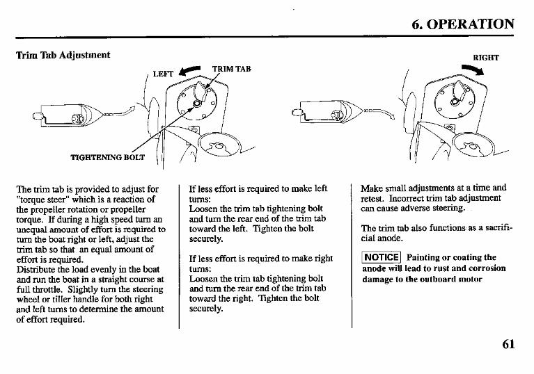
The trim tab is provided to adjust for “torque steer” which is a reaction of the propeller rotation or propeller torque. If during a high speed turn an unequal amount of effort is required to turn the boat right or left, adjust the trim tab so that an equal amount of effort is required. Distribute the load evenly in the boat and run the boat in a straight course at full throttle. Slightly turn the steering wheel or tiller handle for both right and left turns to determine the amount of effort required.
If less effort is required to make left tums: Loosen the trim tab tightening bolt and turn the rear end of the trim tab toward the left. Tighten the bolt securely.
If less effort is required to make right tums: Loosen the trim tab tightening bolt and turn the rear end of the trim tab toward the right. Tighten the bolt securely.
RIGHT
Make small adjustments at a time and retest. Incorrect trim tab adjustment can cause adverse steering.
The trim tab also functions. as a sacrifi- cial anode.
INoTICE] Painting or coating the anode will lead to rust and corrosion damage to the outboard motor
61
6. OPERATION (MOTOR PROTECTIONSYSTEM)
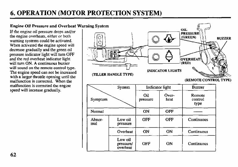
Engine Oil Pressure and Overheat Warning System If the engine oil pressure drops and/or the engine overheats, either or both warning systems could be activated. When activated the engine speed will decrease gradually and the green oil pressure indicator light will turn OFF and’the red overheat indicator light will turn ON. A continuous buzzer will sound on the remote control type. The engine speed can not be increased with a larger throttle opening until the malfunction is corrected. When the malfunction is corrected the engine speed will increase gradually.
(TILLER HANDLE TYPE) INDICATOR LIGHTS
(REMOTE CONTROL TYPE)
Buzzer
Remote control
type
I Normal 1 ON 1 OFF I - I
Abnor- mal
Low oil OFF pressure
Overheat ON
OFF Continuous
ON Continuous
Low oil pressure/ OFF overheat
ON Continuous J
62
6. OPERATION (MOTOR PROTECTION SYSTEM)
When the oil pressure warning sys- tems is activated:
1. Stop the engine immediately and check the engine oil level (refer to page 29).
2.If the oil is up to the recommended level, restart the engine. If the oil pressure warning system stops after 30 seconds, the system is normal.
If the throttle was closed suddenly after cruising at full throttle, the engine speed may drop below the specified idle speed. This could cause the oil pressure warning system to activate momentarily.
3. If the oil pressure warning system stays activated after 30 seconds, return to the closest boat landing and contact your closest authorized Honda Marine dealer.
COOLING SYSTEM INDICATOR
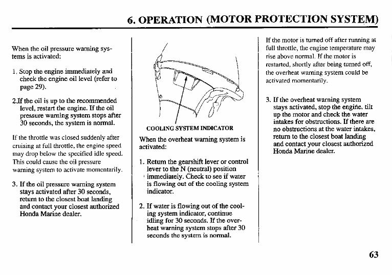
When the overheat warning system is activated:
1. Return the gearshift lever or control lever to the N (neutral) position
1 immediately. Check to see if water is flowing out of the cooling system indicator.
2. If water is flowing out of the cool- ing system indicator, continue idling for 30 seconds. If the over- heat warning system stops after 30 seconds the system is normal.
If the motor is turned off after running at full throttle, the engine temperature may rise above normal. If the motor is restarted, shortly after being turned off, the overheat warning system could be activated momentarily.
3. If the overheat warning system stays activated, stop the engilie. tilt up the motor and check the water intakes for obstructions. If there are no obstructions at the water intakes, return to the closest boat landing and contact your closest authorized Honda Marine dealer.
63
6. OPERATION (MOTOR PROTECTION SYSTEM)
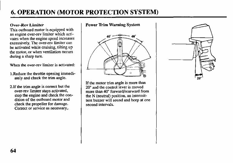
Over-Rev Limiter This outboard motor is equipped with an engine over-rev limiter which acti- vates when the engine speed increases excessively. The over-rev limiter can be activated while cruising, tilting up the motor, or when ventilation occurs during a sharp turn.
When tire over-rev limiter is activated:
1 .Reduce the throttle opening immedi- ately and check the trim angle.
23 the trim angle is correct but the over-rev limiter stays activated, stop the engine and check the con- dition of the outboard motor and check the propeller for damage. Correct or service as necessary,.
Power llim Warning System
If the motor trim angle is more than 20” and the control lever is moved more than 40’ forward/rearward from the N (neutral} position, an intermit- tent buzzer will sound and beep at one second intervals.
64
6. OPERATION (MOTOR PROTECTION SYSTEM)
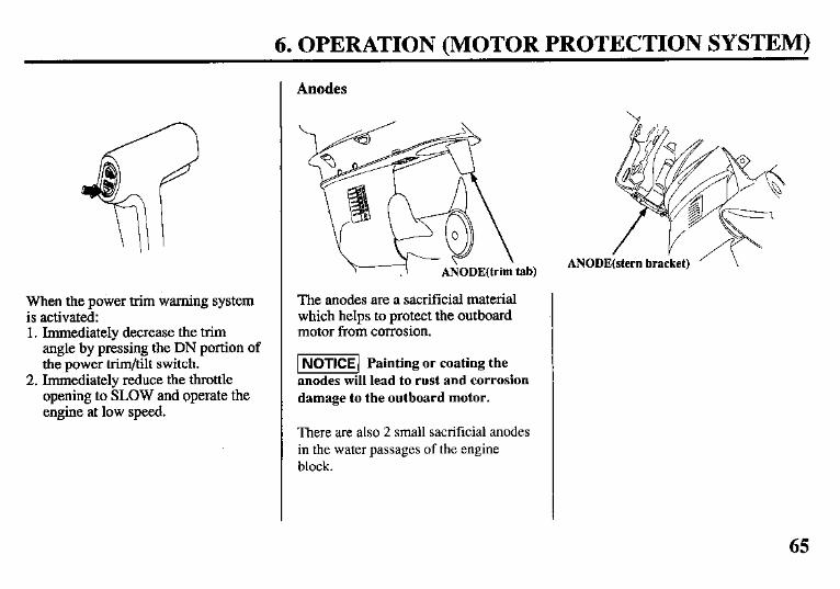
When the power trim warning system is activated: 1. Immediately decrease the trim
angle by pressing the DN portion of the power trim/tilt switch.
2. Immediately reduce the throttle opening to SLOW and operate the engine at low speed.
Anodes
The anodes are a sacrificial material which helps to protect the outboard motor from corrosion.
INoTICE] Painting or coating the anodes will lead to rust and corrosion damage to the outboard motor.
There are also 2 small sacrificial anodes in the water passages of the engine block.
65
6. OPERATION
Shallow Water Operation
[NOTICE1Excessive trim/tilt angle during operation can cause the pro- peller to raise out of the water and cause propeller ventilation and engine over-revving. Excessive trim/tilt angle can also damage the water pump and overheat the engine.
When operating in shallow water, tilt the motor up to prevent the propeller and gear case from hitting the bottom (refer to pages 54 and 57). With the motor tilted up, operate the motor at low speed.
Monitor the cooling system indicator for water discharge. Be sure that the motor is not tilted so high that the water intakes are out of the water.
If an excessive amount of throttle is used when operating in forward gear, the motor will return to the transom angle adjusting rod. (Gas assisted tilt type).
66
If the motor trim angle is more than 20’ and the control lever is moved more than 40” forward/rearward from the N (neutral) position, the power trim warning system will be activated (refer to page 6.4). (Power trim/tilt type).
6. OPERATION
High Altitude Operation
At high altitude, the standard carbure- tor air-fuel mixture will be excessively rich. Performance will decrease, and fuel consumption will increase.
High altitude performance can be improved by installing a smaller diam- eter main fuel jet in the carburetor and readjusting the pilot screw. If you always operate the outboard motor at altitudes higher than 6,000 feet above sea level, have your authorized Honda Marine dealer perform these carbure- tor modifications.
Even with suitable carburetor jetting, engine horsepower will decrease approximately 3.5% for each 1,000 foot increase in altitude. The effect of altitude on horsepower will be greater than this if no carburetor modification is made.
w Operation of the out- board motor at an altitude lower than the carburetor is jetted for may result in reduced performance, overheating, and serious engine damage caused by an excessively lean air/fuel mixture.
67
7. STOPPING THE ENGINE (TILLER HANDLE TYPE)
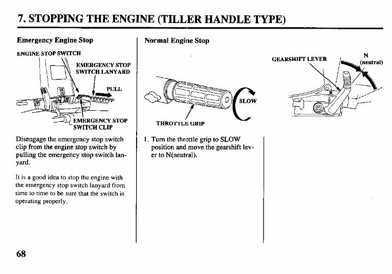
Emergency Engine Stop
ENGINE STOP SWITCH
EMERGENCY STOP SWITCH LANYARD
I
SWITCH CLIP
Disengage the emergency stop switch clip from the engine stop switch by pulling the emergency stop switch lan- yard.
It is a good idea to stop the engine with the emergency stop switch lanyard from time to time to be sure that the switch is operating properly.
Normal Engine Stop
1. Turn the throttle grip to SLOW position and move the gearshift lev- er to N(neutral).
GEA ,RSHIFF LEVER ’ N
68
7. STOPPING THE ENGINE (TILLER HANDLE TYPE)
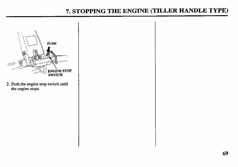
ENGINE STOP SWITCH
2. Push the engine stop switch until the engine stops.
69
7. STOPPING THE ENGINE (REMOTE CONTROL TYPE)
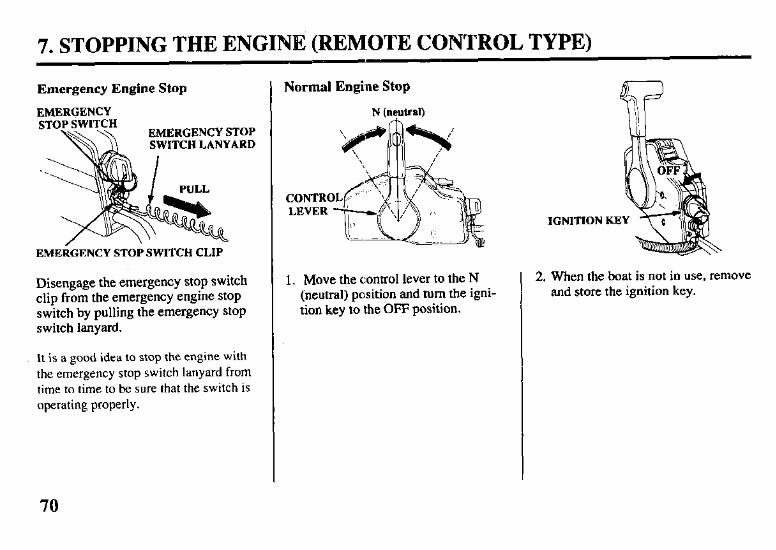
Emergency Engine Stop
,nn”uI.~.
OP SWITCH ERGENCY STOP ITCH LANYARD
EMERGENCY STOP SWITCH CLIP
Disengage the emergency stop switch clip from the emergency engine stop switch by pulling the emergency stop switch lanyard.
It is a good idea to stop the engine with the emergency stop switch lanyard from time to time to be sure that the switch is operating properly.
Normal Engine Stop
N (neutral)
1. Move the control lever to the N (neutral) position and turn the igni- tion key to the OFF position.
IGNITION KE
2. When the boat is not in use, remove and store the ignition key.
70
8. TRANSPORTING
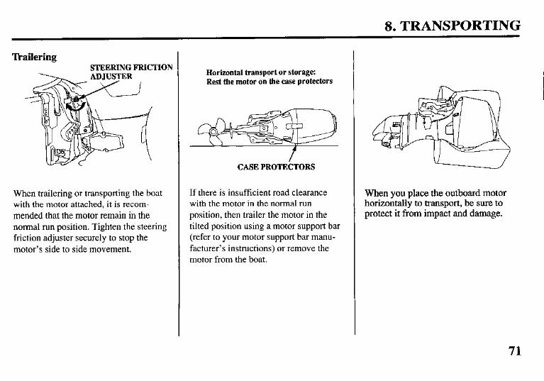
Tkailering STEERING FRICTION
When trailering or transporting the boat with the motor attached, it is recom- mended that the motor remain in the normal run position. Tighten the steering friction adjuster securely to stop the motor’s side to side movement.
Horizontal transport or storage: Rest the motor on the case protectors
CASE PROTEbTORS
If there is insufficient road clearance with the motor in the normal run position, then trailer the motor in the tilted position using a motor support bar (refer to your motor support bar manu- facturer’s instructions) or remove the motor from the boat.
When you place the outboard motor horizontally to transport, be sure to protect it from impact and damage.
71
9. CLEANING AND FLUSHING
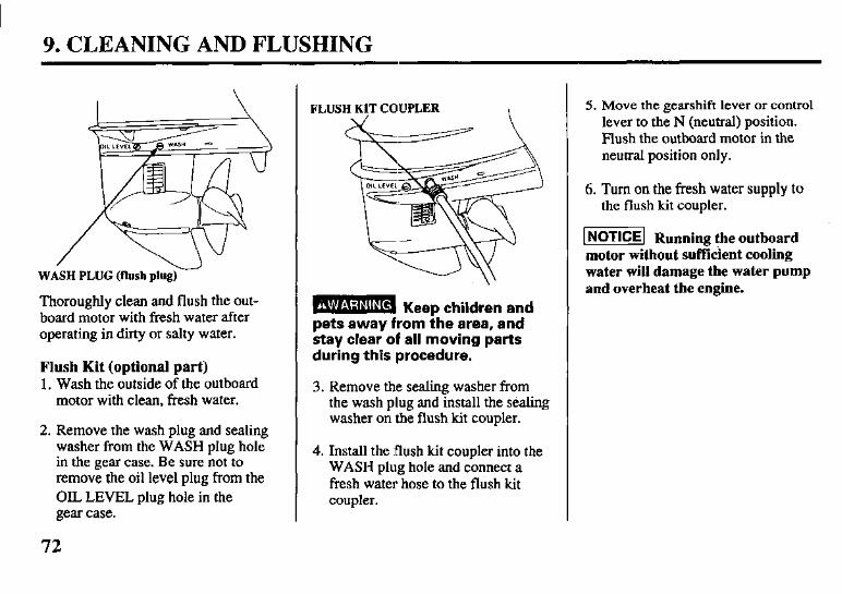
I w WASH PLUG (flush plug)
Thoroughly clean and flush the out- board motor with fresh water after operating in dirty or salty water.
Flush Kit (optional part) 1. Wash the outside of the outboard
motor with clean, fresh water.
2. Remove the wash plug and sealing washer from the WASH plug hole in the gear case. Be sure not to remove the oil level plug from the OIL LEVEL plug hole in the gear case.
72
FLUSH KIT COUPLER
B KeeD children and pets away from ihe area, and stay clear of all moving parts during this procedure.
3. Remove the sealing washer from the wash plug and install the sealing washer on the flush kit coupler.
4. Install the flush kit coupler into the WASH plug hole and connect a fresh water hose to the flush kit coupler.
5. Move the gearshift lever or control lever to the N (neutral) position. Blush the outboard motor in the neutral position only.
6. Turn on the fresh water supply to the flush kit coupler.
m Running the outboard motor without sufficient cooling water will damage the water pump and overheat the engine.
9. CLEANING AND FLUSHING
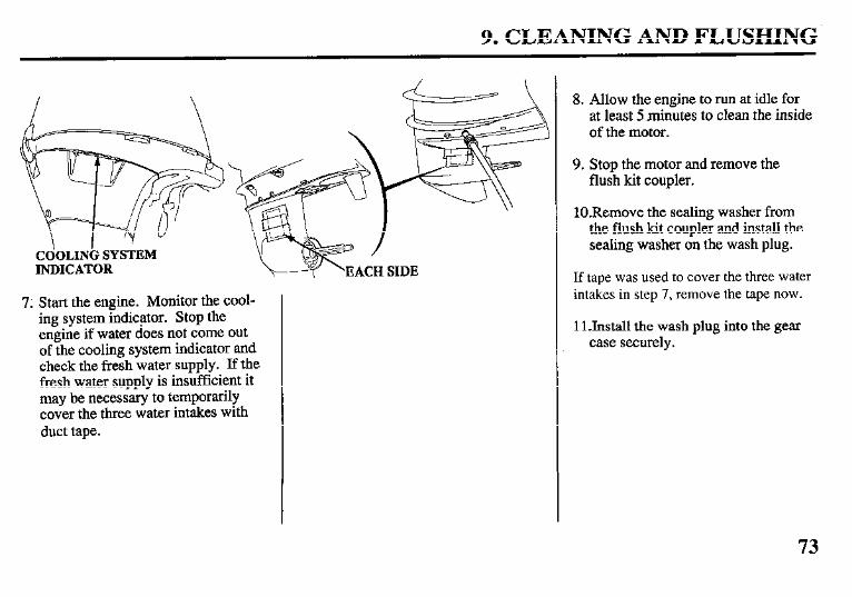
CdOLINi; SYSTEM INDICATOR
7. Start the engine. Monitor the cool- ing system indicator. Stop the engine if water does not come out of the cooling system indicator and check the fresh water supply. If the fresh water supply is insufficient it may be necessary to temporarily cover the three water intakes with duct tape.
8. Allow the engine to run at idle for at least 5 minutes to clean the inside of the motor.
9. Stop the motor and remove the flush kit coupler.
lO.Remove the sealing washer from the flush kit coupler and install the sealing washer on the wash plug.
If tape was used to cover the three water intakes in step 7, remove the tape now.
11 Jnstall the wash plug into the gear case securely.
73
10. MAINTENANCE
Periodic maintenance and adjustment are important to keep the motor in the best operating condition. Service and inspect according to the MAINTENA- NCE SCHEDULE.
Stop the engine before performing any maintenance.
If it is necessary to run the engine make sure the area is well ventilated. Never run the engine in an enclosed or confined area.
- Exhaust contains poisonous carbon monoxide gas; exposure can cause loss of consciousness and may lead to death.
(NOTICEI Running the outboard motor without sufficient cooling water will damage the water pump and overheat the engine.
To maintain the cooling system effi- ciency, flush the outboard motor with fresh water after operating in salt water or dirty water. Make sure there is at least 2 inches of water above the ventilation plate. Or follow the flushing procedure (refer to pages 72 and 73).
74
10. MAINTENANCE
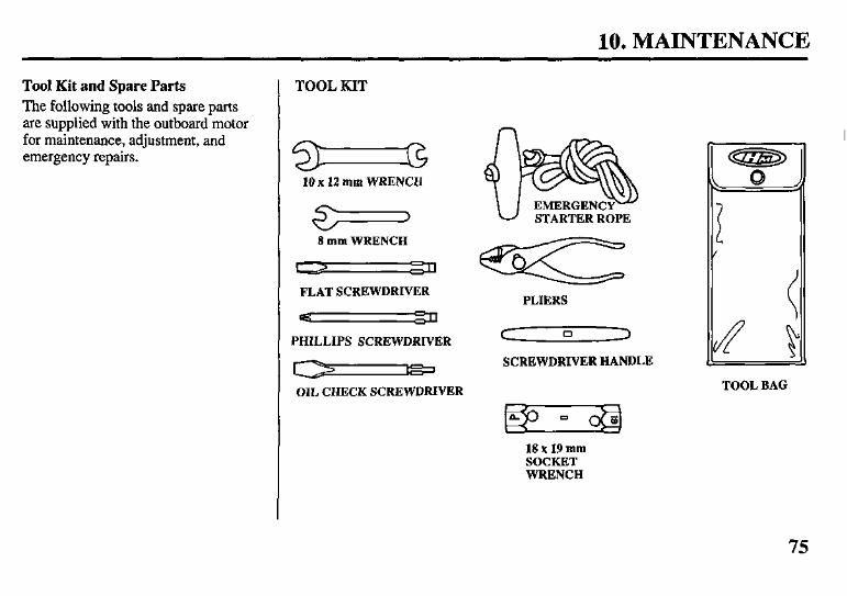
Tool Kit and Spare Parts The following tools and spare parts are supplied with the outboard motor for maintenance, adjustment, and emergency repairs.
TOOL KIT
10 x 12 mm WRENCH
>
8 mm WRENCH
FLAT SCREWDRIVER
PHILLIPS SCREWDRIVER
OIL CHECK SCREWDRIVER
STARTER ROPE
PLIERS
C 0 3
SCREWDRIVER HANDLE
TOOL BAG
18 x 19 mm SOCKET WRENCH
75
10. MAINTENANCE
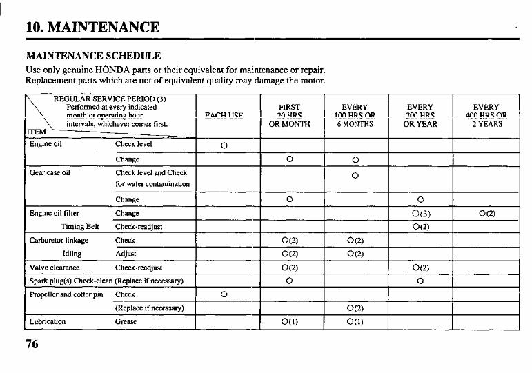
MAINTENANCE SCHEDULE
Use only genuine HONDA parts or their equivalent for maintenance or repair. Replacement parts which are not of equivalent quality may damage the motor.
10. MAINTENANCE
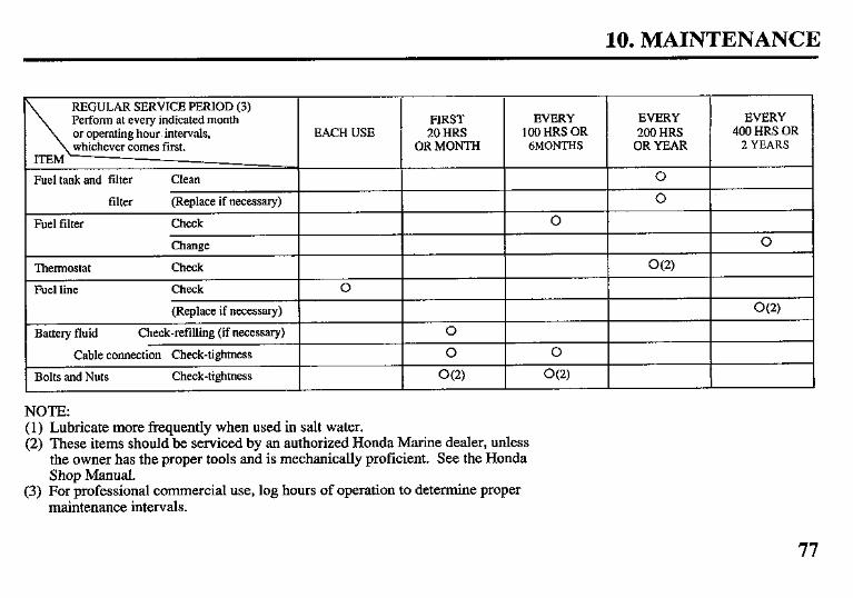
, REGULAR SERVICE PERIOD (3)
\
Perform at every indicated month or op,erating hour 1 intervals, whichever comes first.
ITEM’
Fuel tank and filter Clean
filter (Replace if necessary)
Fuel filter Check
Thermostat
Fuel line
Change
Check
Check
(Replace if necessary)
Battery fluid Check-refilling (if necessary) 0
Cable connection Check-tightness 0
Bolts and Nuts Check-tightness O(2)
-
EACH USE
0
-
FIRST 20 HRS
OR MONTH
-
EVERY 100 HRS OR
6MONTHS
0
NOTE: (1) Lubricate more frequently when used in salt water. (2) These items should be serviced by an authorized Honda Marine dealer, unless
the owner has the proper tools and is mechanically proficient. See the Honda Shop Manual.
(3) For professional commercial use, log hours of operation to determine proper maintenance intervals.
EVERY 200 HRS
OR YEAR
0 0
O(2)
- I
EVERY 400 HRS OR
2 YEARS
77
10. MAINTENANCE
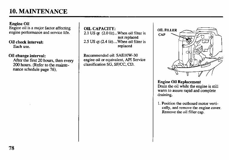
Engine Oil Engine oil is a major factor affecting engine performance and service life.
Oil check interval: Each use.
Oil change interval: After the first 20 hours, then every 200 hours. (Refer to the mainte- nance schedule page 76).
OIL CAPACITY: 2.1 US qt (2.0 lit)...When oil filter is
not replaced 2.5 US qt (2.4 lit)....When oil filter is
replaced
Recommended oil: SAElOW-30 engine oil or equivalent, API Service classification SG, SF/CC, CD.
Engine Oil Replacement Drain the oil while the engine is still warm to assure rapid and complete draining.
1. Position the outboard motor verti- cally, and remove the engine cover. Remove the oil filler cap.
78
10. MAINTENANCE
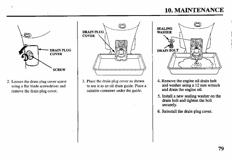
DRAINPLUG
2. Loosen the drain plug cover screw using a flat blade screwdriver and remove the drain plug cover.
3. Place the drain plug cover as shown to use it as an oil drain guide. Place a suitable container under the guide.
4. Remove the engine oil drain bolt and washer using a 12 mm wrench and drain the engine oil.
5. Install a new sealing washer on the drain bolt and tighten the bolt secure1 y.
6. Reinstall the drain plug cover.
79
I 10. MAINTENANCE
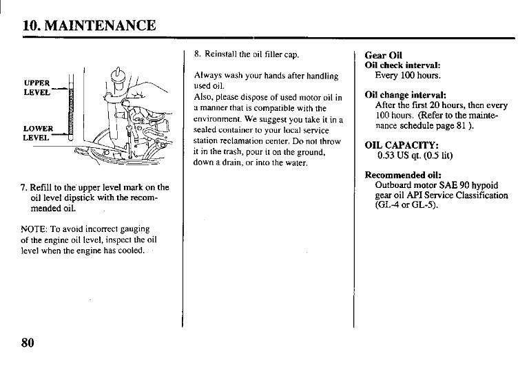
7. Refill to the-upper level mark on the oil level dipstick with the recom- mended oil.
NOTE: To avoid incorrect gauging of the engine oil level, inspect the oil level when the engine has cooled..
8. Reinstall the oil filler cap.
Always wash your hands after handling used oil. Also, please dispose of used motor oil in a manner that is compatible with the environment. We suggest you take it in a sealed container to your local service station reclamation center. Do not throw it in the trash, pour it on the ground, down a drain, or into the water.
Gear Oil Oil check interval:
Every 100 hours.
Oil change interval: After the first 20 hours, then every 100 hours. (Refer to the mainte- nance schedule page 81 ).
OIL CAPACITY: 0.53 US qt. (0.5 lit)
Recommended oil: Outboard motor ME 90 hypoid gear oil API Service Classification (GL-4 or GL-5).
80
10. MAINTENANCE
LEVEL PLUG \
DRAIN
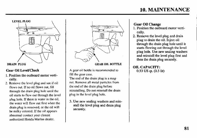
Gear Oil Level/Check 1. Position the outboard motor verti-
cally. 2. Remove the level plug and see if oil
flows out. If no oil flows out, fill through the drain plug hole until the oil starts to flow out through the level plug hole. If there is water in the oil, the water will flow out first when the drain plug is removed, or the oil will be milky colored. If the oil appears abnormal contact your closest authorized Honda Marine dealer.
GEAR OIL BOTTLE
A gear oil bottle is recommended to fill the gear case. The end of the drain plug is a mag- net. Remove all metal particles from the end of the drain plug before reinstalling. Do not reinstall the drain plug in the level plug hole.
3. Use new sealing washers and rein- stall the level plug and drain plug securely.
Gear Oil Change 1. Position the outboard motor verti-
cally. 2. Remove the level plug and drain
plug to drain the oil. Inject oil through the drain plug hole until it starts flowing out through the level plug hole. Use new sealing washers and reinstall the level plug first and then the drain plug securely.
OIL CAPACITY: 0.53 US qt. (0.5 lit)
81
10. MAINTENANCE
Spark Plugs To ensure proper engine operation, the spark plugs must be properly gapped and free of deposits.
Check-replace interval: After the first 20 hours, then every 200 hours. (Refer to the mainte- nance schedule page 76).
Recommended spark plug: DR7EA (NGK), X22ESR-U (NIPPON DENSO) Use only the recommended spark plugs or equivalent.
I- Spark plugs which have an improper heat range may cause engine damage.
1. Allow the engine to cool. The spark plugs will be hot if the engine has been running.
2. Remove the engine cover.
PLUG CAPS .. v
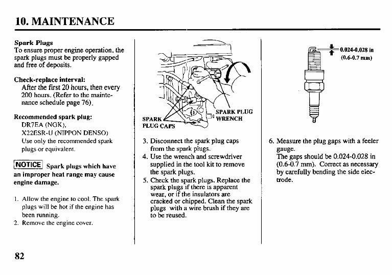
3. Disconnect the spark plug caps from the spark plugs.
4. Use the wrench and screwdriver supplied in the tool kit to remove the spark plugs.
5. Check the spark plugs. Replace the spark plugs .if there is apparent wear, or if the insulators are cracked or chipped. Clean the spark plugs with a wire brush if they are to be reused.
0.0244028 in (0.6-0.7 mm)
6. Measure the plug gaps with a feeler gauge. The gaps should be 0.024-0.028 in - _ (0.6-0.7 mm). Correct as necessary by carefully bending the side elec- trode.
82
10. MAINTENANCE
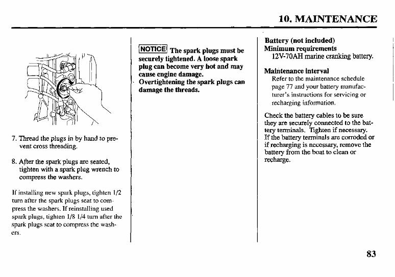
7. Thread the plugs in by hand to pre- vent cross threading.
8. After the spark plugs are seated, tighten with a spark plug wrench to compress the washers.
If installing new spark plugs, tighten l/2 turn after the spark plugs seat to com- press the washers. If reinstalling used spark plugs, tighten l/8 l/4 turn after the spark plugs seat to compress the wash- ers.
1-1 The spark plugs must be securely tightened. A loose spark plug can become very hot and may cause engine damage. Overtightening the spark plugs can damage the threads.
Battery (not included) Minimum requirements
12V-70AH marine cranking battery.
Maintenance interval Refer to the maintenance schedule page 77 and your battery manufac- turer’s instructions for servicing or recharging information.
Check the battery cables to be sure they are securely connected to the bat- tery terminals. Tighten if necessary. If the battery terminals are corroded or if recharging is necessary, remove the battery from the boat to clean or recharge.
83
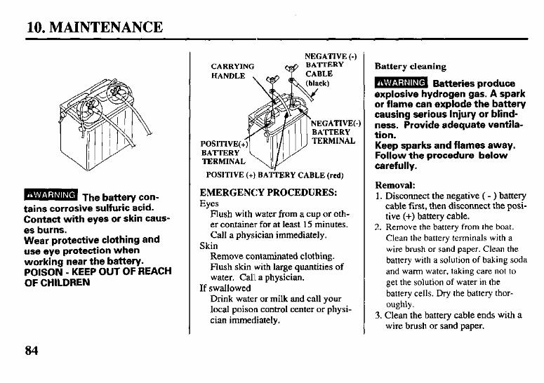
10. MAINTENANCE
tains corrosive sulfuric &id. Contact with eyes or skin caus- es burns. Wear protective clothing and use eye protection when working near the battery. POISON - KEEP OUT OF REACH OF CHILDREN
NEGATIVE (-) CARRYING
POSITIVE (+) BATTERY CABLE (red)
EMERGENCY PROCEDURES: Eyes
Flush with water from a cup or oth- er container for at least 15 minutes. Call a physician immediately.
Skin Remove contaminated clothing. Flush skin with large quantities of water. Call a physician.
If swallowed Drink water or milk and call your local poison control center or physi- cian immediately.
Battery cleaning
B Batteries produce exDlosive hydrogen gas. A spark or ilame can explode the battery causing serious Injury or blind- ness. Provide adequate ventila- tion. Keep sparks and flames away. Follow the procedure below carefully.
Removal: 1. Disconnect the negative ( - > battery
cable first, then disconnect the posi- tive (+) battery cable.
2. Remove the battery from the boat. Clean the battery terminals with a wire brush or sand paper. Clean the battery with a solution of baking soda and warm water, taking care not to get the solution of water in the battery cells. Dry the battery thor- oughly.
3. Clean the battery cable ends with a wire brush or sand paper.
84
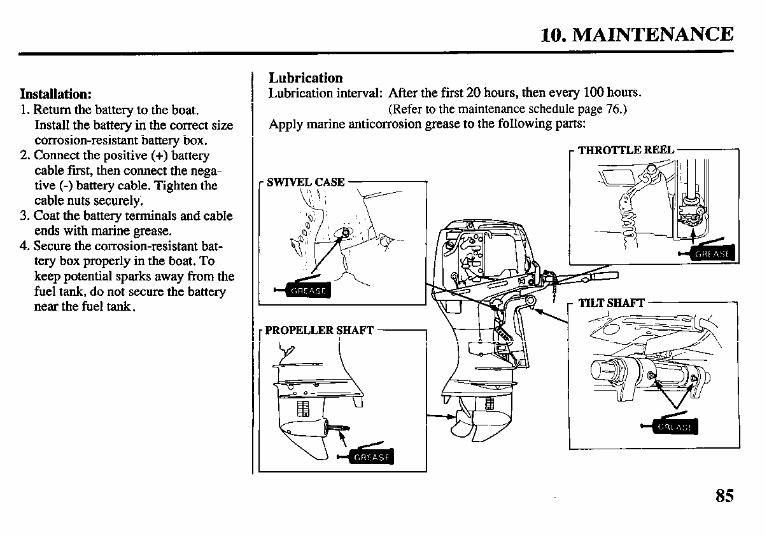
10. MAINTENANCE
Installation: 1. Return the battery to the boat.
Install the battery in the correct size corrosion-resistant battery box.
2. Connect the positive (+) battery cable first, then connect the nega- tive (-) battery cable. Tighten the cable nuts securely.
3. Coat the battery terminals and cable ends with marine grease.
4. Secure the corrosion-resistant bat- tery box properly in the boat. To keep potential sparks away from the fuel tank, do not secure the battery near the fuel tank.
Lubrication Lubrication interval: After the first 20 hours, then every 100 hours.
(Refer to the maintenance schedule page 76.1 Apply marine anticorrosion grease to the following parts:
,- THROTTLE REEL ~1
1 r PROPELLER SHAFT - \
85
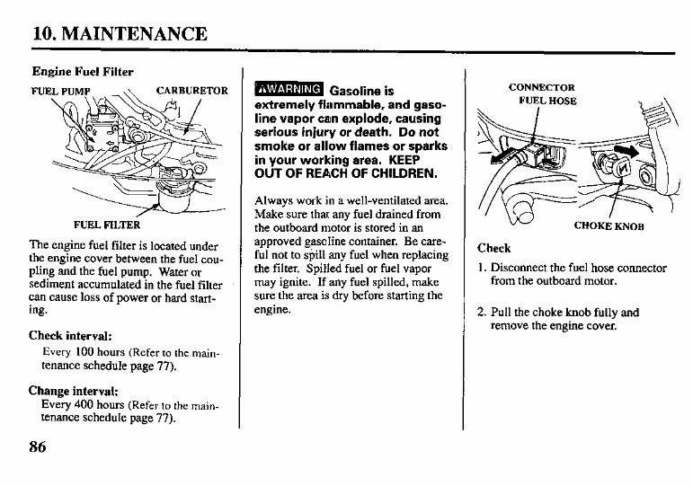
10. MAINTENANCE
Engine Fuel Filter
ARBURETOR
FUEL FILTER
The engine fuel filter is located under the engine cover between the fuel cou- pling and the fuel pump. Water or sediment accumulated in the fuel filter can cause loss of power or hard start- ing.
Check interval: Every 100 hours (Refer to the main- tenance schedule page 77).
Change interval: Every 400 hours (Refer to the main- tenance schedule page 77).
B Gasoline is extremely flammable, and gaso- line vapor an explode, causing serious injury or death. Do not smoke or allow flames or sparks in your working area. KEEP OUT OF REACH OF CHILDREN.
Always work in a well-ventilated area. Make sure that any fuel drained from the outboard motor is stored in an approved gasoline container. Be care- ful not to @ill any fuel when replacing the filter. Spilled fuel or fuel vapor may ignite. If any fuel spilled, make sure the area is dry before starting the engine.
CONNECTOR FUEL HOSE ,\
Check
CHOKE KNOB
1. Disconnect the fuel hose connector from the outboard motor.
2. Pull the choke knob fully and remove the engine cover.
86
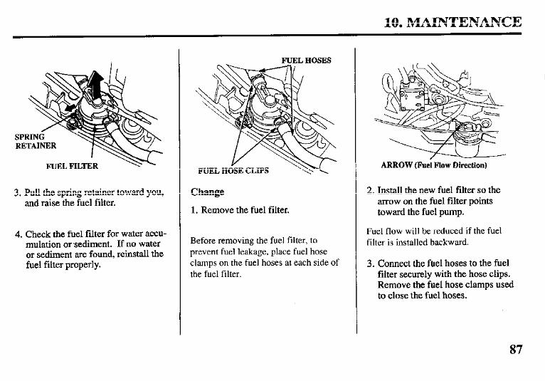
10. MAINTENANCE
FUEL FILTER
3. Pull the spring retainer toward you, and raise the fuel filter.
4. Check the fud filter for water accu- mulation or sediment. If no water or sediment are found, reinstall the fuel filter properly.
Change
1. Remove the fuel filter.
Before removing the fuel filter, to prevent fuel leakage, place fuel hose clamps on the fuel hoses at each side of the fuel filter.
ARROW (Fuel Flow Direction)
2. Install the new fuel filter so the arrow on the fuel filter points toward the fuel pump.
Fuel flow will be reduced if the fuel filter is installed backward.
3. Connect the fuel hoses to the fuel filter securely with the hose clips. Remove the fuel hose clamps used to close the fuel hoses.
87

10. MAINTENANCE
4. Securely connect the fuel hose con- nector to the outboard motor page 34.
5. Prime the engine using the primer bulb page 35. Check for fuel leaks. &pair any fuel leaks if necessary.
If loss of power or hard starting are found to be caused by excessive water or sediment accumulation in the fuel filter, inspect the fuel tank. Clean the fuel tank and tank filter if necessary. It may be necessary to drain the fuel tank completely and refill with fresh gasoline.
Fuel Tank and Filter
Cleaning interval: Every 200 hours (Refer to the maintenance schedule page 77).
Inspect the condition of the fuel cap gasket, fuel hose, and the O-ring seals in the fuel hose connectors. Replace the fuel cap gasket, hose, or fuel con- nectors if they are cracked, damaged or leak fuel. Be sure the fuel hose is not kinked.
Fuel Tank Cleaning
1. Disconnect the fuel hose from the fuel tank.
extremely flammable, and gaso- line vapor can explode, causing serious injury or death. Do not smoke or allow flames or sparks in your working area. KEEP OUT OF REACH OF CHILDREN.
2. Empty the gasoline from the fuel tank into an approved gasoline con- tainer. Pour in a small quantity of fresh gasoline, and clean the tank thoroughly. Drain and dispose of the gasoline properly.
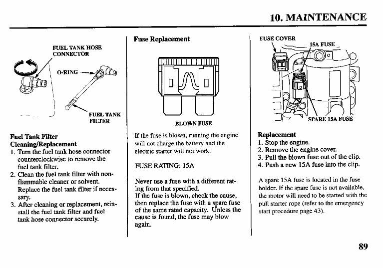
10. MAINTENANCE
FUEL TANK HOSE CONNECTOR
FUEL TANK FILTER
Fuel Tank Filter Cleaning/Replacement 1. Turn the fuel tank hose connector
counterclockwise to remove the fuel tank filter.
2. Clean the fuel tank filter with non- flammable cleaner or solvent. Replace the fuel tank filter if neces- sary.
3. After cleaning or replacement, rein- stall the fuel tank filter and fuel tank hose connector securely.
Fuse Replacement
BLOWN FUSE
If the fuse is blown, running the engine will not charge the battery and the electric starter will not work.
RUSE RATING: 15A
Never use a fuse with a different rat- ing from that specified. If the fuse is blown, check the cause, then replace the fuse with a spare fuse of the same rated capacity. Unless the cause is found, the fuse may blow again.
FUSE COVER
Replacement 1. Stop the engine. 2. Remove the engine cover. 3. Pull the blown fuse out of the clip. 4. Rush a new 15A fuse into the clip.
A spare 15A fuse is located in the fuse holder. If the spare fuse is not available, the motor will need to be started with the pull starter rope (refer to the emergency start procedure page 43).
89
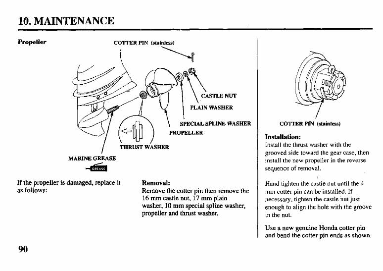
10. MAINTENANCE
Propeller COTTER PIN Mainless)
I CASTLE NUT
PLAIN WASHER
SPECIAL SPLINE WASHER
PROPELLER
I THRUST W’hER
MARINE GREASE
-asiih
If the propeller is damaged, replace it as follows:
Removal: Remove the c:otter pin then remove the 16 mm castle nut, 17 mm plain washer, 10 mm special spline washer, propeller and thrust washer.
COTTER PIN (stainless)
Installation: Install the thrust washer with the grooved side toward the gear case, then install the new propeller in the reverse sequence of removal.
Hand tighten the castle nut until the 4 mm cotter pin can be installed. If necessary, tighten the castle nut just enough to align the hole with the groove in the nut.
Use a new genuine Honda cotter pin and bend the cotter pin ends as shown.
90
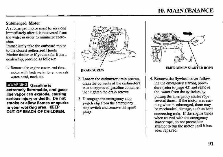
10. MAINTENANCE
Submerged Motor A submerged motor must be serviced immediately after it is recovered from the water in order to minimize corro- sion. Immediately take the outboard motor to the closest authorized Honda Marine dealer or if you are far from a dealership, proceed as follows:
1. Remove the engine cover, and rinse motor with fresh water to remove salt water, sand, mud, etc.
B Gasoline is extremely flammable, and gaso- line vapor can explode, causing serious injury or death. Do not smoke or allow flames or sparks in your working area. KEEP OUT OF REACH OF CHILDREN.
DRAIN SCREW
2. Loosen the carburetor dram screws, drain the contents of the carburetors into an approved gasoline container, then tighten the dram screws.
3. Disengage the emergency stop switch clip from the emergency stop switch and remove the spark plugs.
EMERGENCY STAR+ER ROPE
4. Remove the flywheel cover follow- ing the emergency starting proce- dure (refer to page 43) and remove the water from the cylinders by pulling the emergency starter rope several times. If the motor was run- ning when it submerged, there may be mechanical damage, such as bent connecting rods. If the engine binds when rotated with the emergency starter rope, do not proceed or attempt to run the motor until it has been repaired.
91
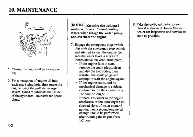
10. MAINTENANCE
5. Change the engine oil (refer to page 78).
6. Put a teaspoon of engine oil into each spark plug hole, then rotate the engine using the pull starter rope several times to lubricate the inside of the cylinders. Reinstall the spark plugs.
INOTICE] Running the outboard motor without suffkient cooiing water will damage the water pump and overheat the engine.
7. Engage the emergency stop switch clip with the emergency stop switch and attempt to start the engine (be sure the water level is at least 2 inches above the ventilation plate).
l If the engine fails to start, remove the spark plugs, clean and dry the electrodes, then reinstall the spark plugs and attempt to start the engine again.
l If the engine starts, and no mechanical damage is evident, continue: to run the engine for a I/2 hour or longer.
l If there was water in the engine crankcase, or the used engine oil showed signs of water contami- nation, then a second engine oil change should be performed after running the engine for a l/2 hour.
8. Take the outboard motor to your closest authorized Honda Marine dealer for inspection and service as soon as possible.
92
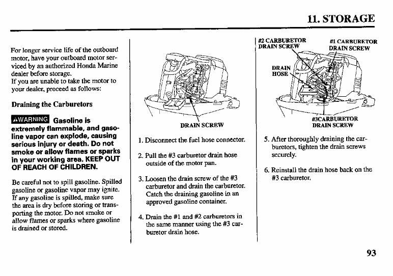
11. STORAGE
For longer service life of the outboard motor, have your outboard motor ser- viced by an authorized Honda Marine dealer before storage. If you are unable to take the motor to your dealer, proceed as follows:
Draining the Carburetors
B Gasoline is extremely flammable, and gaso- line vapor can explode, causing serious injury or death. Do not smoke or allow flames or sparks in your working area. KEEP OUT OF REACH OF CHILDREN.
Be careful not to spill gasoline. Spilled gasoline or gasoline vapor may ignite. If any gasoline is spilled, make sure the area is dry before storing or trans- porting the motor. Do not smoke or allow flames or sparks where gasoline is drained or stored.
DRAIIi SCREW
1. Disconnect the fuel hose connector.
2. Pull the #3 carburetor drain hose outside of the motor pan.
3. Loosen the drain screw of the #3 carburetor and dram the carburetor. Catch the draining gasoline in an approved gasoline container.
4. Drain the #l and #2 carburetors in the same manner using the #3 car- buretor dram hose.
f2 CARBURETOR #I CARBURETOR DRAIN SCREW
DRAIN SCREW
5. After thoroughly draining the car- buretors, tighten the drain screws securely.
6. Reinstall the drain hose back on the #3 carburetor.
93
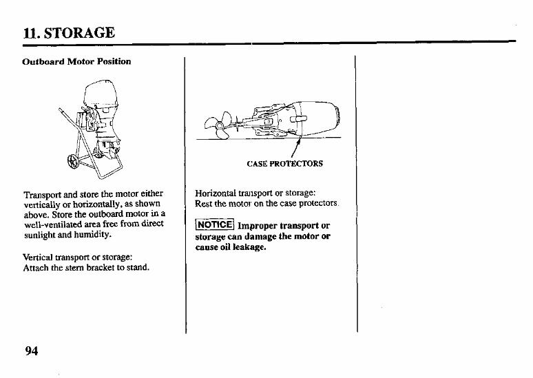
11. STORAGE
Outboard Motor Position
Transport and store the motor either vertically or horizontally, as shown above. Store the outboard motor in a well-ventilated area free from direct sunlight and humidity.
Vertical transport or storage: Attach the stem bracket to stand.
CASE PROTECTORS
Horizontal transport or storage: Rest the motor on the case protectors.
lNoTlCE/ Improper transport or storage can damage the motor or cause oil leakage.
94
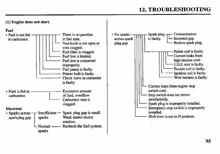
12. TROUBLESHOOTING
(1) Engine does not start.
Fuel l Fuel is not fed
to carburetor. There is no gasoline in fuel tank. Vent knob is not open or vent clogged. Fuel filter is clogged. Fuel line is kinked. Fuel line is connected improperly. Fuel pump is faulty. Primer bulb is faulty. Check valve in connector is faulty
clogged. Electrical l Sparks across Insufficient - Spark plug gap is small.
sparlcplug gap sparks Weak starter motor rotation.
Normal - Recheck the fuel system. spark
- Spark plug
-E
Contamination is faulty. Incorrect gap
Broken spark plug
-llE
Pulser coil is faulty. Current leaks from high tension cord. C.D.I. unit is faulty. Exciter coil is faulty. Ignition coil is faulty. Wire harness is faulty.
. Current leaks from engine stop switch cord.
- Stop switch does not return satisfactorily.
- Spark plug is improperly installed. - Emergency stop switch is improperly installed.
. Shift lever is not in N position.
l No sparks - across spark plug gap
95
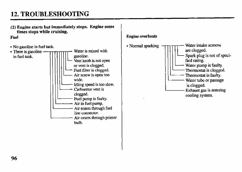
12. TROUBLESHOOTING
(2) Engine starts but immediately stops. Engine some times stops while cruising.
Fuel
. No gasoline in fuel tank. l There is gasoline -
in fuel tank. Iii Water is mixed with gasoline. Vent knob is not open or vent is clogged.
- Fuel filter is clogged. - Air screw is open too L wide.
Idling speed is too slow. - Carburetor vent is
clogged. - Fuel pump is faulty. - Air in fuel pump. - Air enters through fuel
line connector. - Air enters through primer
bulb.
Engine overheats
. Normal sparking
1
!iE Water intake screens are clogged. Spark plug is not of speci- fied rating. Water pump is faulty. Thermostat is clogged. Thermostat is faulty. Water tube or passage is clogged.
Exhaust gas is entering cooling system.
96
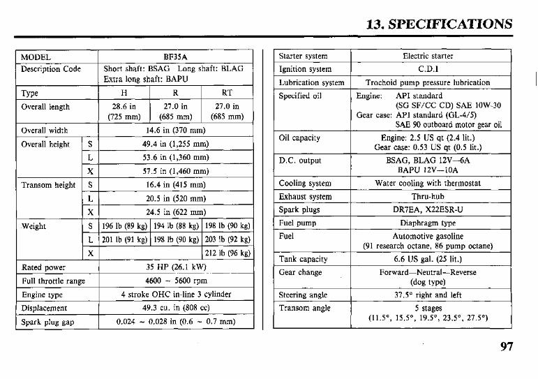
13. SPECIFICATIONS
Starter system Electric starter
Ignition system C.D.1
Lubrication system Trochoid pump pressure lubrication
Specified oil Engine: API standard (SG SF/CC CD) SAE low-30
Gear case: API standard (GL-4/S) SAE 90 outboard motor gear oil
Oil capacity Engine: 2.5 US qt (2.4 lit.) Gear case: 0.53 US qt (0.5 lit.)
D.C. output BSAG, BLAG 12V-6A BAPU 12V-1OA
Cooling system Water cooling with thermostat
Exhaust system Thru-hub
Spark plugs DRIIEA, X22ESR-U
Fuel pump Diaphragm type
Fuel Automotive gasoline (91 research octane, 86 pump octane)
Tank capacity 6.6 US gal. (25 lit.)
Gear change Forward-Neutral-Reverse (dog type)
Steering angle 37.5” right and left
Transom angle 5 stages (11.5”, 15.5”, 19.5”, 23.5”, 27.5”)
97
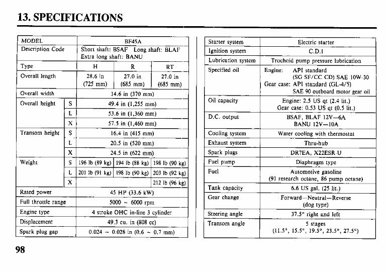
13. SPECIFICATIONS
API standard SG SF/CC CD
98
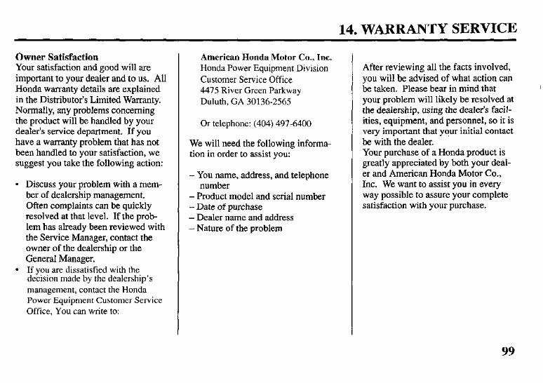
14. WARRANTY SERVICE
Owner Satisfaction Your satisfaction and good will are important to your dealer and to us. All Honda warranty details are explained in the Distributor’s Limited Warranty. Normally, any problems concerning the product will be handled by your dealer’s service department. If you have a warranty problem that has not been handled to your satisfaction, we suggest you take the following action:
l Discuss your problem with a mem- ber of dealership management. Often complaints can be quickly resolved at that level. If the prob- lem has already been reviewed with the Service Manager, contact the owner of the dealership or the General Manager.
l If you are dissatisfied with the decision made by the dealership’s management, contact the Honda Power Equipment Customer Service Office, You can write to:
American Honda Motor Co., Inc. Honda Power Equipment Division Customer Service Office 4475 River Green Parkway Duluth, GA 30136-2565
Or telephone: (404) 497-6400
We will need the following informa- tion in order to assist you:
- You name, address, and telephone number
- Product model and serial number - Date of purchase - Dealer name and address - Nature of the problem
After reviewing all the facts involved, you will be advised of what action can be taken. Please bear in mind that your problem will likely be resolved at the dealership, using the dealer’s facil- ities, equipment, and personnel, so it is very important that y?ur initial contact be with the dealer. Your purchase of a Honda product is greatly appreciated by both your deal- er and American Honda Motor Co., Inc. We want to assist you in every way possible to assure your complete satisfaction with your purchase.
99
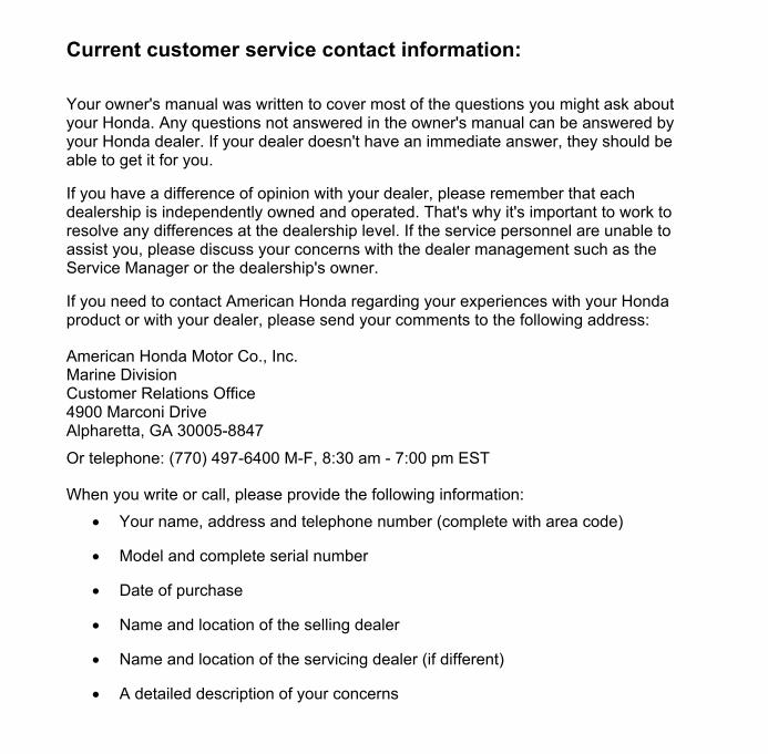
Current customer service contact information: Your owner's manual was written to cover most of the questions you might ask about your Honda. Any questions not answered in the owner's manual can be answered by your Honda dealer. If your dealer doesn't have an immediate answer, they should be able to get it for you.
If you have a difference of opinion with your dealer, please remember that each dealership is independently owned and operated. That's why it's important to work to resolve any differences at the dealership level. If the service personnel are unable to assist you, please discuss your concerns with the dealer management such as the Service Manager or the dealership's owner.
If you need to contact American Honda regarding your experiences with your Honda product or with your dealer, please send your comments to the following address:
American Honda Motor Co., Inc. Marine Division Customer Relations Office 4900 Marconi Drive Alpharetta, GA 30005-8847
Or telephone: (770) 497-6400 M-F, 8:30 am - 7:00 pm EST
When you write or call, please provide the following information:
• Your name, address and telephone number (complete with area code)
• Model and complete serial number
• Date of purchase
• Name and location of the selling dealer
• Name and location of the servicing dealer (if different)
• A detailed description of your concerns
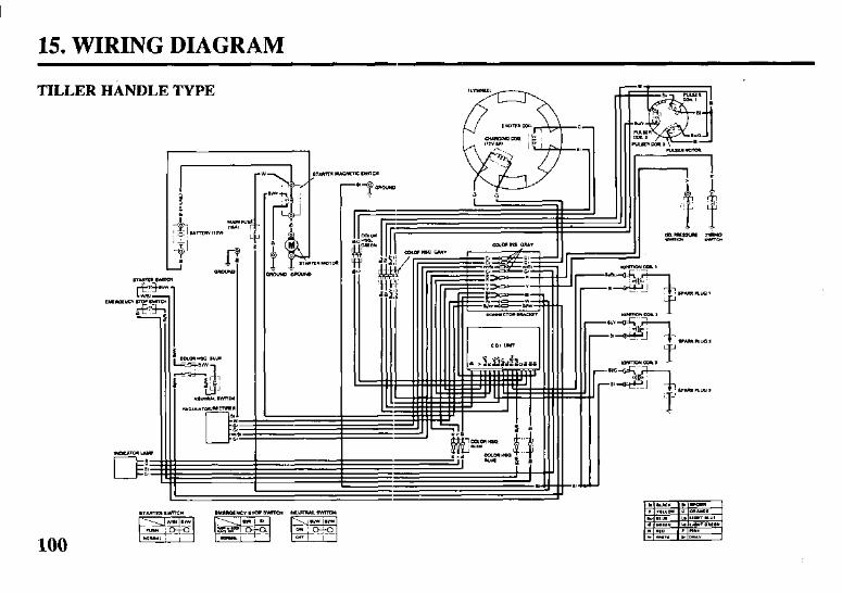
15. WIRING DIAGRAM
TILLER HANDLE TYPE
“ml - r*rra “-pW r-
100
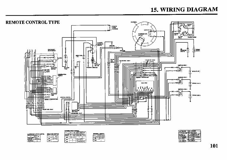
15. WIRING DIAGRAM
REMOTE CONTROL TYPE
s- !-
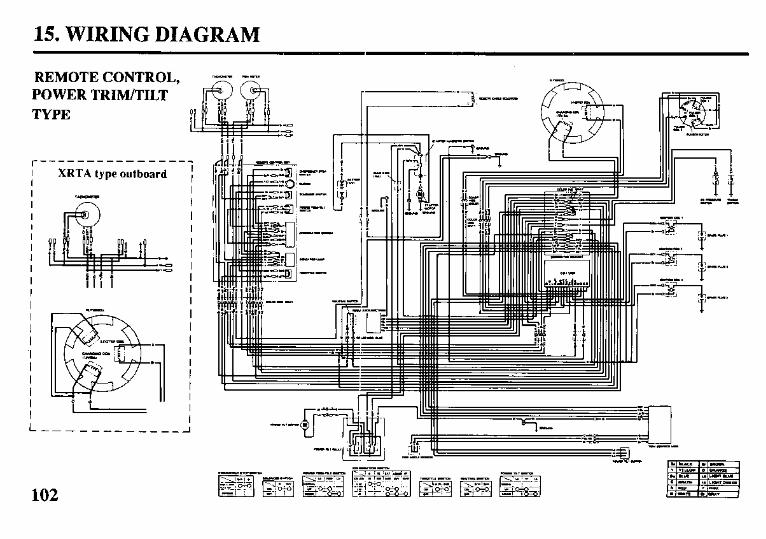
15. WIRING DIAGRAM
REMOTE CONTROL, .-.. -- POWER TRIM/TILT TYPE P
XRTA type outboard I I I I I I I I I I I I I I I I I I I I I I
L------------A
102
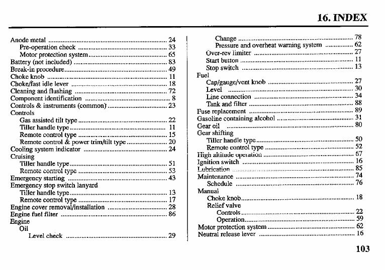
16. INDEX
Anode metal .................................................................... 24 Pre-operation check ................................................... 33 Motor protection system.. ........................................... 65
Battery (not included) ...................................................... 83 Break-in procedure.. ......................................................... 49 Choke knob ..................................................................... 11 Choke/fast idle lever ....................................................... 18 Cleaning and flushing ..................................................... 72 Component identification ................................................. 8 Controls & instruments (common) .................................. 23 Controls
Gas assisted tilt type _ .................................................. 22 Tiller handle type ....................................................... 11 Remote control type ................................................... 15 Remote control & power trim/tilt type ....................... 20
Cooling system indicator ................................................ 24 Cruising
Tiller handle type.. ...................................................... 5 1 Remote control type ................................................... 53
Emergency starting ......................................................... 43 Emergency stop switch lanyard
Tiller handle type ........................................................ 13 Remote control type ................................................... 17
Engine cover removal/installation .................................. 28 Engine fuel filter ............................................................. 86 Engine
Oil Level check .......................................................... 29
Change .................................................................. 78 Pressure and overheat warning system ................ 62
Over-rev limiter ......................................................... 27 Start button ................................................................. 11 Stop switch ................................................................ 13
Fuel - Cap/gauge/vent knob . . . . . . . . . . . . . . . . . . . . . . . . . . . . . . . . . . . . . . . . . . . . . . . . . 27 Level . . . . . . . . . . . . . . . . . . . . . . . . . . . . . . . . . . . . . . . . . . . . . . . . . . . . . . . . . . . . . . . . . . . . . . . . 30 Line connection ......................................................... 34 Tank and filter ............................................................ 88
Fuse replacement ............................................................ 89 Gasoline containing alcohol ............................................ 3 1 Gear oil ......................................................................... 80 Gear shifting
Tiller handle type.. ...................................................... Remote control type ................................................... z;
High altitude operation .................................................... 67 Ignition switch ................................................................ 16 Lubrication ...................................................................... 85 Maintenance .................................................................... 74
Schedule .................................................................... 76 Manual
Choke knob ................................................................. 18 Relief valve
Controls.. ............................................................... 22 Operation ............................................................... 59
Motor protection system .................................................. 62 Neutral release lever ....................................................... 16
103
16. INDEX
Oil pressure indicator light .............................................. 14. Oil pressure indicator light/buzzer .................................. 19 Other checks .................................................................... 33 Over-rev limiter ............................................................... 64. Overheat indicator light .................................................. 14. Overheat indicator light/buzzer ....................................... 19 Power tilt switch (motor pan)
Controls ...................................................................... 21 Operation ................................................................... 59
Power trim warning system ............................................ 64 Power trim/tilt switch (remote control lever) .................. 20 Pre-operation checks ....................................................... 28 Propeller .......................................................................... 90
And cotter pin ............................................................ 3:! Remote control
Friction adjustment .................................................... 33 Lever ......................................................................... 1.‘;
Safety ........................................................................... 6 Information .................................................................. 7 Labels .......................................................................... 6
Shallow water operation .................................................. 66 Shift lever ........................................................................ 11 Spark plug ....................................................................... 82 Specifications .................................................................. 97 Starting the engine
Remote control type .................................................. 40 Tiller handle type ....................................................... 36
Steering ........................................................................ 51
Friction adjustment (common) .................................. 32 Stem bracket
Pre-operation check ..................................................... 33 Stopping the engine
Remote control type .................................................. 70 liller handle type.. ...................................................... 68
Storage ........................................................................ 94 Submerged motor ............................................................ 91 Tachometer ...................................................................... 21 Throttle
Friction knob ............................................................. 12 Grip ........................................................................ 12 Opening indicator ...................................................... 12
Tilt lever ......................................................................... 22 Tilt lock lever
Controls ...................................................................... 23 Operation ................................................................... 60
Tilting motor Gas assisted tilt type .................................................. 54 Power trim/tilt type .................................................... 57
Tool kit ......................................................................... 33 Tool kit and spare parts ................................................... 75 Transom angle adjusting rod ........................................... 26 Transporting .................................................................... 7 1 Trim meter
Controls ................................ . ..................................... 21 Operation .................................................................... 58
Trim tab ........................................................................ 23
104
16. INDEX
Trim tab adjustment ........................................................ 61 Troubleshooting .............................................................. 95
Starting problems ....................................................... 48 Warranty service ............................................................. 99 Water intakes ................................................................... 25 Wiring diagram ............................................................. 100
105

MEMO

MEMO

MEMO

HONDA mmwnr-
BF35A145A Owner's Manual
1 I 1 I I 1 1 I <SUPPLEMENT>-
@ 1993 American Honda Motor Co., inc. - All Rights Reeerved
I I I I I I I I I I I I I I

Thank you for purchasing a Honda Outboard Motor.
This owner’s manual supplement covers specific information about the Honda BF45AM LHTA type out- board motor. Refer to the BF35A/45A owner’s manual for all other information.
The owner’s manual and this supple- ment contain information on how to operate your new outboard motor safely. Please read them carefully.
Keep the owner’s manual and this supplement handy, so you can refer to them at any time, and be sure they accompany the outboard motor if you sell it.
We recommend that you mad the warranty policy to fully understand your rights and nxponsibilities. The warranty policy is a separate docu- ment provided by your dealer.
The information in this publication was in effect at the time of approval for printing. American Honda Motor Co., Inc. merves the right to discon- tinue or change specifications or de- sign at any time without notice and without incurring any obligation whatever. No part of this publica- tion may be reproduced without writ- ten permission.
01993 AmeticanHondaMotorCo.,Inc. All Rights Reserved .’
1
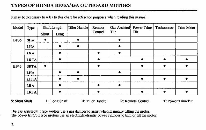
TYPES OF HONDA BF35A/45A OUTBOARD MOTORS
It may be necessary to refix to this chart for reference purposes when reading this manual.
1 Model Shaft Length TiIler Handle Remote Gas Assisted Power Trim/ Tachometer Trim Meter
Short I-m2 Control Tilt Tilt
BF35 SHA l 0 0
LHA 0 0 0
LRA 0 0 a I
BF45
S: Short Shaft L: Long Shaft H: Tiller Handle R: Remote Control T: Power TkQI’ilt
The gas assisted tilt type motors use a gas damper to assist when manually tilting the motor. The power trim/tilt type motors use an electric/hydraulic power cylinder to trim or tilt the motor.
2
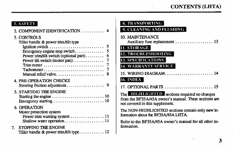
CONTENTS (LHTA)
2. COMPONENT IDENTIFICATION ........... 4
3. CONTROLS Tiller handle 8z power trim/tilt type
Ignition switch .......................... 5 Emergency engine stop switch. ............. 5 Power trim/tilt switch (optional part). ........ 6 Power tilt switch (motor pan). .............. 7 Trimmeter ............................. 7 Tachometer. ............................ 7 Manual relief valve. ...................... 8
4. PRE-OPERATION CHECKS Steering friction adjustment. ................. 9
5. STARTING THE ENGINE Starting the engine ......................... 10 Emergency starting. ........................ 10
6. OPERATION Motor protection system
Power trim warning system ................ 11 Shallow water operation. .................. 11
7. STOPPING THE ENGINE Tillerhandle &powertrim/tilttype ............ 12
10. MAINTENANCE Auxiliary fuse replacement . . . . . . . . . . . . . . . . . . 13
15. WIRING DIAGRAM.. . . . . . . . . . . . . . . . . . . . . . 14
[d,l
17. OPTIONALPARTS . . . . . . . . . . . . . . . . . . . . . . . 15
The- sections required no changes from the BF35A/45A owner’s manual. ‘I&se sections ate not covered in this supplement.
The NON-HIGHLIGHTED sections contain only new in- formation about the BP35A/45A LHTA.
Refer to the BP35A/45A owner’s manual for all other in- formation.
I 3

2. COMPONENT IDENTIFICATION (LHTA)
POWER TILT SWITCH
BUZZER
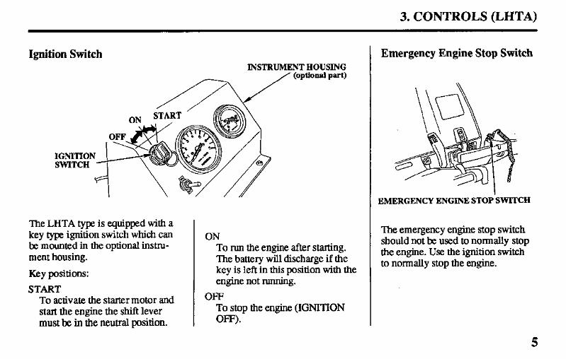
3. CONTROLS (LHTA)
Ignition Switch INSTRUMENT HOUSING
(optional part)
IGNITIO SWITCH
The LHTA type is equipped with a key type ignition switch which can be mounted in the optional instru- ment housing.
Key positions:
START To activate the starter motor and start the engine the shift lever must he in the neutral position.
ON To run the engine after starting. The battery will discharge if the key is left in this position with the engine not running.
OFF To stop the engine (IGNITION OFF).
Emergency Engine Stop Switch
EMERGENCY ENGINE STOP SWITCH
The emergency engine stop switch should not be used to normally stop the engine. Use the ignition switch to nonnalIy stop the engine.
5
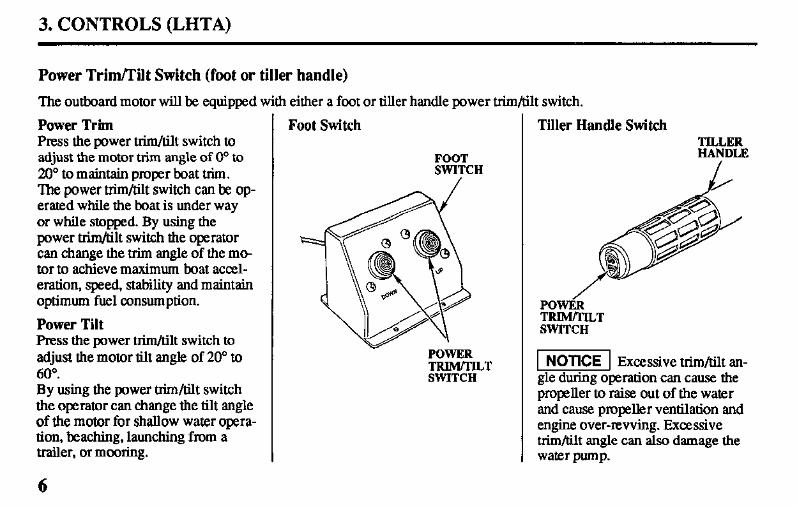
3. CONTROLS (LHTA)
Power Trim/Tilt Switch (foot or tiller handle)
The outboard motor will be equipped with either a foot or tiller handle power trim/tilt switch.
Power Trim Foot Switch Press the power trim/tilt switch to adjust the motor trim angle of 0" to 20” to maintain proper boat trim. The power trim/tilt switch can be op- erated while the boat is under way or while stopped. By using the power trim/tilt switch the operator can change the trim angle of the mo- tor to achieve maximum boat accel- eration, speed, stability and maintain optimum fuel c43nsumption.
Power Tilt Press the power trim/tilt switch to adjust the motor tilt angle of 20” to 6o”. By using the power trim/tilt switch the operator can change the tilt angle of the motor for shallow water opera- tion, beaching, launching from a trailer, or mooring.
FOOT SWITCH
Tiller Handle Switch
6
POWER TRIM/TILT SWITCH
TILLER HANDLE
POWiR TRIM/TILT SWITCH
1 NOTICE 1 Excessive trim/tilt an- gle during operation can cause the propeller to raise out of the water and cause propeller ventilation and engine over-revving. Excessive trim/tilt angle can also damage the water pump.
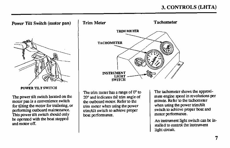
3. CONTROLS (LHTA)
Power Tilt Switch (motor pan) Trim Meter
POWER TILT SWITCH
The power tilt switch located on the motor pan is a convenience switch for tilting the motor for trailering, or performing outboard maintenance. This power tilt switch should only be operated with the boat stopped and motor off.
Tachometer
TRIMMETER
TACHOMETER m
The trim meter has a range of 0” to 20’ and indicates thb trim angle of the outboard motor. Refer to the trim meter when using the power trim/tilt switch to achieve proper boat performance.
The tachometer shows the approxi- mate engine speed in revolutions per minute. Refer to the tachometer when using the power trim/tilt switch to achieve proper boat and motor performance.
An instrument light switch can be in- stalled to control the instrument light circuit.
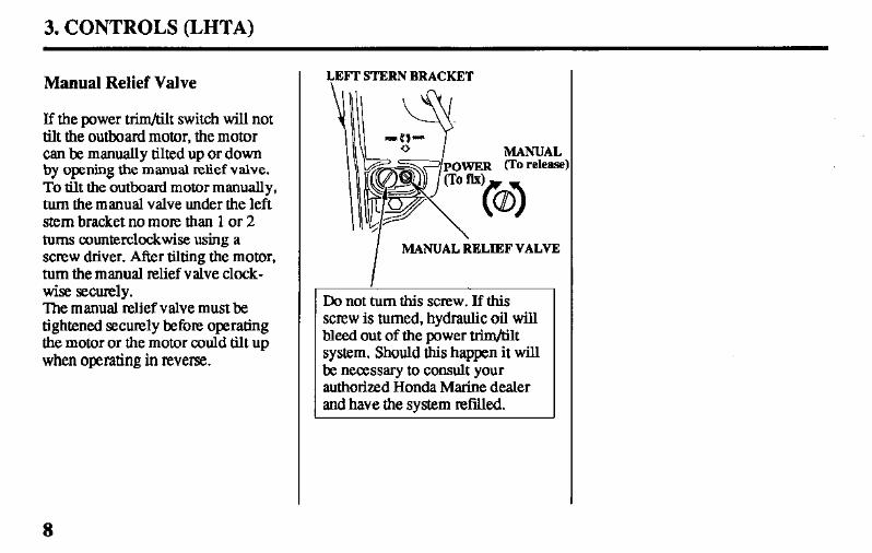
3. CONTROLS (LHTA)
Manual Relief Valve
If the power trim/tilt switch will not tilt the outboard motor, the motor can be manually tilted up or down by opening the manual relief valve. To tilt the outboard motor manually, turn the manual valve under the left stem bracket no more than 1 or 2 tums counterclockwise using a screw driver. After tilting the motor, turn the manual relief valve clock- wise securely. The manual relief valve must be tightened securely before operating the motor or the motor could tilt up when operating in reverse.
LEmSTERNBRACKET
MANUAL
I MANUALI~ELIEFVALVE
Do not turn this screw. If this screw is turned, hydraulic oil will bleed out of the power trim/tilt system. Should this happen it will be necessary to consult your authorized Honda Marine dealer and have the system refilled.
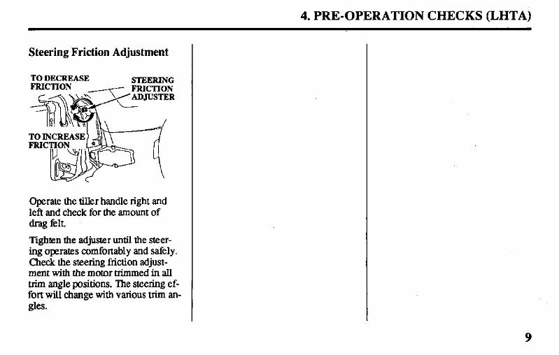
4. PRE-OPERATION CHECKS (LHTA)
Steering Friction Adjustment
TO DECREASE STEERING
Operate the tiller handle right and left and check for the amount of drag felt.
Tighten the adjuster until the steer- ing operates comfortably and safely. Check the steering friction adjust- ment with the motor trimmed in all trim angle positions. The steering ef- fort will change with various trim an- gles.
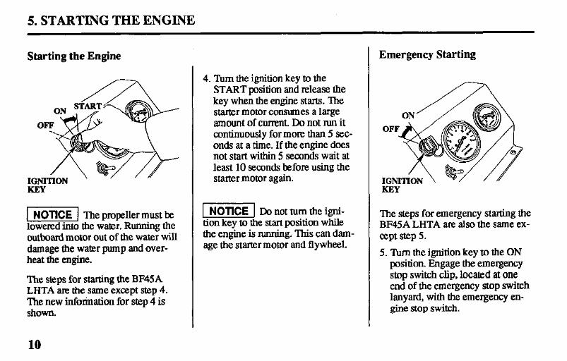
5. STARTING THE ENGINE
Starting the Engine
1 NOTICE 1 The propeller must be lowered into the water. Running the outboard motor out of the water will damage the water pump and over- heat the engine.
‘Ihe steps for starting the BF45A LHTA are the same except step 4. The new inforination for step 4 is ShOWll.
4. Turn the ignition key to the START position and release the key when the engine starts. ‘Ihe starter motor consumes a large amount of cumznt. Do not run it continuously for more than 5 sec- onds at a time. If the engine does not start within 5 seconds wait at least 10 seconds before using the starter motor again.
1 NOTICE 1 Donottumtheigni- tion key to the start position while the engine is running. This can dam- age the starter motor and flywheel.
Emergency Starting
The steps for emergency starting the BF45A LHTA are also the same ex- cept step 5.
5. ‘lbm the ignition key to the ON position. Engage the emergency stop switch clip, located at one end of the emergency stop switch lanyard, with the emergency en- gine stop switch.
10
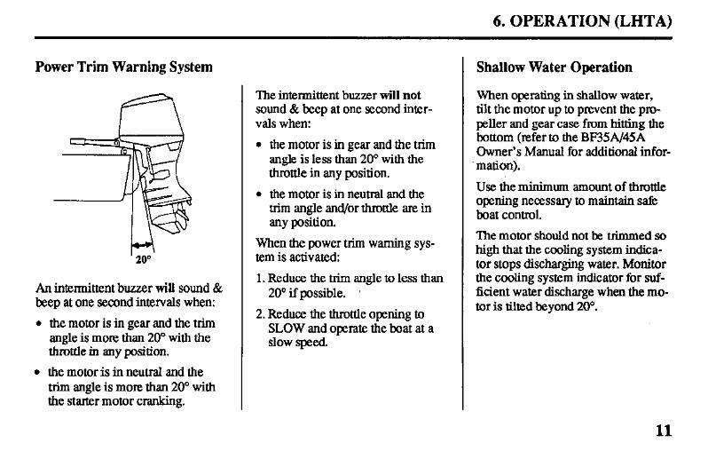
6. OPERATION (LHTA)
Power Trim Warning System
An intennittent buzzer wig sound & beep at one second intervals when:
l the motor is in gear and the trim angle is mom than 20” with the throttle in any position.
l the motor is in neutral and the trim angle is more than 20’ with the starter motor cranking.
The intermittent buzzer will not sound & beep at one second inter- vals when:
l the motor is in gear and the trim angle is less than 20° with the throttle in any position.
l the motor is in neutral and the trim angle and/or throttle are in any position.
When the power trim warning sys- tem is activated:
1. Reduce the trim angle to less than 20” if possible.
2. Reduce the throttle opening to SLOW and operate the boat at a slow speed.
Shallow Water Operation
When operating in shallow water, tilt the motor up to prevent the pro- peller and gear case from hitting the bottom (refer to the BF35A/45A Owner’s Manual for additional infor- mation).
Use the minimum amount of throttle opening necessary to maintain sat% boat control.
The motor should not be trimmed so high that the cooling system indica- tor stops discharging water. Monitor the cooling system indicator for suf- ficient water discharge when the mo- tor is tilted beyond 20’.
11
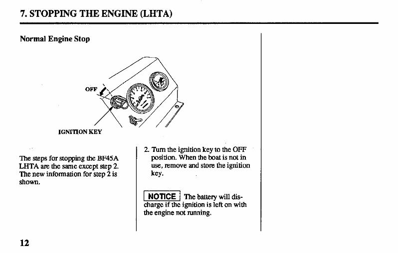
7. STOPPING THE ENGINE (LHTA)
Normal Engine Stop
0
IGNRION KEY
The steps for stopping the BF45A LHTA are the same except step 2. The new information for step 2 is ShOWn.
2. Turn the ignition key to the OFF position. When the ?&at is not in use, remove and store the ignition key.
1 NOTICE 1 The battery will dis- charge if the ignition is left on with the engine not running.
12
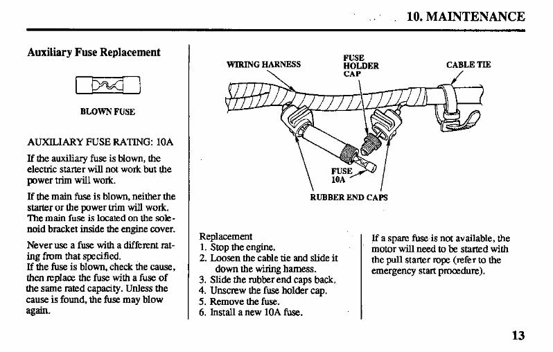
_ 10. MAINTENANCE
Auxiliary Fuse Replacement
I P4 1 BLOWN FUSE
AUXILIARY FUSE RATING: 10A
If the auxiliary fuse is blown, the electric starter will not work but the power trim will work.
If the main fuse is blown, neither the starter or the power trim will work. ‘Ihe main fuse is located on the sole- noid bracket inside the engine cover.
Never use a fuse with a different rat- ing from that specified. If the fuse is blown, check the cause, then replace the fuse with a fuse of the same rated capacity. Unless the cause is found, the fuse may blow again.
WIRING HARNESS \
FUSE HOLDER CAP
CABLE TIE /
RUBBER END CAPS
Replacement 1. Stop the engine. 2. Loosen the cable tie and slide it
down the wiring harness. 3. Slide the rubber end caps back. 4. Unscrew the fuse holder cap. 5. Remove the fuse. 6. Install a new 10A fuse.
If a spam fuse.is not available, the motor will need to be started with the pull starter rope (refer to the emergency start procedure).
13
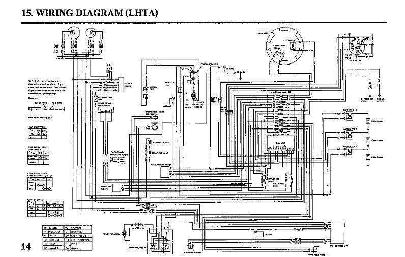
15. WIRING DIAGRAM (LHTA)
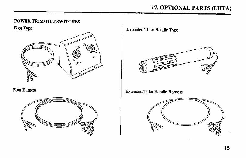
17. OPTIONAL PARTS (LHTA)
POWER TRIM/TILT SWITCHES
Foot ‘Qpe
Foot Hamess
Extended Tiller Handle ‘I)pe
Extended Tiller Handle Harness
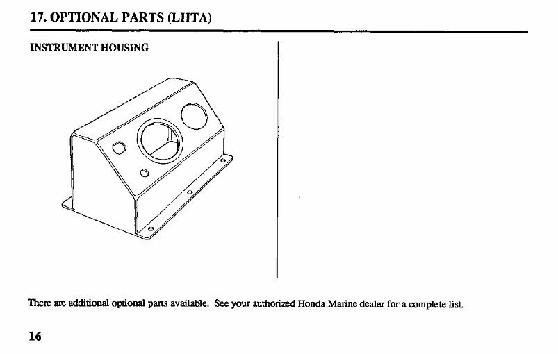
17. OPTIONAL PARTS (LHTA)
INSTRUMENT HOUSING
There axe additional optional parts available. See your authorized Honda Marine dealer for a complete list.
16

1 I
I I
31 ZV36OS 2509304
00X31 -ZV3-6SO0 PRINTED IN U.S.A.
I I I I I I I I I I I I