Embed Size (px)
Citation preview
Melting and boiling pointLaboratory Guide

© BÜCHI Labortechnik AG | Version A
Contents
1 Introduction 3
1.1 What is a melting point? 3
1.2 Why measuring melting points? 3
1.3 Who measures melting points? 4
1.4 The boiling point 5
2 Theoretical basis for the measurement of boiling points and melting points 6
2.1 Physical states 6
2.2 Phase transitions 7
2.2.1 Phase diagrams for 1-material systems (state diagrams) 8
2.3 What happens during melting? 9
2.4 The boiling point – what happens during evaporation? 10
2.5 The range between the boiling and the melting point 12
2.6 Melting point depression and the mixed melting point 13
2.6.1 Melting point depression 13
2.6.2 Mixed melting point 13
2.6.3 The eutectic point 14
3 Principles and methods of melting point determination 15
3.1 Methods of melting point determination 15
3.1.1 Determining the melting point in the capillary tube 16
3.1.2 Immediate melting point 16
3.2 Principles of melting point determination 18
3.2.1 Melting point determination according to the pharmacopoeia 19
3.2.2 Thermodynamic determination of melting points 20
3.3 Melting point determination yesterday and today – an overview 21
3.3.1 Instruments for melting point determination over the course of years 21
3.3.2 From silicone oil to the metal block 21
4 Melting point determination using the BUCHI M-565 23
4.1 Operating principle of the BUCHI M-565 instrument 24
4.1.1 Automatic determination of melting point 24
4.1.2 Metal heating block 25
4.2 Structure of the BUCHI Melting Point M-565 25
4.3 Melting point determination procedure with the BUCHI M-565 26
4.3.1 Sample preparation 26
4.3.2 M-565 device settings 27
4.3.3 Measurement according to US Pharmacopeia 29
4.3.4 Calibration and verification of the Melting Point M-565 instrument 32
4.4 Flow charts for a melting point determination with the BUCHI M-565 33
4.4.1 Substance with a known melting point or range 34
4.4.2 Substance with an unknown melting point or range 35
4.5 Boiling point determination with the BUCHI Melting Point M-565 36
4.6 Data quality – accurate control 37
4.7 Technical terminology 39
4.8 List of Melting Point M-560/565 instruments, accessories and spare parts 41
4.8.1 Instruments 41
4.8.2 Accessories 41
4.8.3 Spare parts 42
4 Melting Point Laboratory guide
© BÜCHI Labortechnik AG | Version A
1 Introduction
1.1 What is a melting point?
There are several material constants that can be used to describe a material, for example, its spe-
cific gravity, light refraction, adsorption capacity, or chromatographic behavior. The melting point is
also one of these constants. Along with the boiling point and the solidification point, it is one of the
important thermal characteristics that describe a material. The melting points of many pure mate-
rials can be measured with great accuracy.
Crystalline materials consist of extremely fine particles that form a certain regular 3-dimensional
structure. These 3-dimensional arrangements are referred to as lattice structures or (crystalline)
lattices. The particles within the lattice are held together by lattice forces.
Whenever this solid structure, the lattice, is heated, the particles in it begin to move more strong-
ly, until finally the forces of attraction between them are no longer strong enough to maintain the
crystalline structure. The lattice is destroyed and the solid material melts. At the melting point a
material shifts from its ordered, solid state to an unordered, liquid state. The stronger the forces of
attraction between the particles within the lattice, the greater the amount of energy that must be
used to overcome them. The melting temperature of a crystalline solid is thus an indicator for the
stability of its lattice. The higher the temperature, the more strongly the lattice structure in question
holds together.
1.2 Why measure melting points?
There are various methods of chemical and physical analysis used to differentiate, identify, and
classify materials. Measurement of the melting point is, among other things, one of these standard
laboratory procedures. It is an experimental and easily performed method of physical analysis
used to find out the identity, the purity, and the thermal stability of a material.
Identification
Pure materials have exactly defined melting points which can be obtained from reference tables.
Thus, the identity of a material can be determined by measuring its melting point: One needs only
to compare the melting point of the substance as determined in the test with the values in the
technical literature. Of course, determination of the melting point alone is not yet enough for the
clear identification of a substance. There may be several substances with the same melting point.
In such cases, the shift in the mixed melting point (refer to Sect. 2.6.2) can provide an indication
about the definitive identification of the material.
Purity
Even slight impurities in a material cause a lowering of its melting point or at least a widening of its
melting range (the material melts within a range of temperatures and not at a precisely definable
melting point).
Melting Point Laboratory guide 5
© BÜCHI Labortechnik AG | Version A
This phenomenon is used to obtain indications about the purity of a material: The smaller the dif-
ference between the measured melting point of the substance and the melting point shown in the
tables, the narrower its melting range and thus the purer the material.
Thermal stability
Many materials change at high temperatures, e.g., decomposition or discoloration. Measurement
of the melting point is one method that can be used to determine how much the material can be
heated without causing chemical changes. This value is useful as an indicator for the thermal sta-
bility of a substance and can be used to suggest a possible temperature for drying.
1.3 Who measures melting points?
Various groups of users use melting point determination in their daily work with chemical sub-
stances. Their priorities and their specific requirements for how the melting point is to be deter-
mined may differ. The needs of users are different, especially with regard to accuracy of measure-
ment and the ability to observe how the substance behaves during the measurement process.
Synthesizing laboratories
A traditional research laboratory continually produces new types of chemical compounds. In or-
der to find out how these new compounds behave, the research scientists observe the melting
process closely.
Often, these researchers are dealing with different substances: They receive about 1 to 4 samples
each week for investigation. Thus, having a high degree of automation for the measurement of
melting points is only of secondary importance for them. Far more important is their ability to ob-
serve the sample comfortably during the melting process.
Analytical laboratories
Analytical laboratories perform the tests done on the receipt of goods (raw products) and when
examining the end products of a production process. Their main interest here is checking the pu-
rity of the products. Their measurements must be as precise as possible. These laboratories ana-
lyze from 10 to 50 samples each week, whereby determination of the melting point is part of their
daily routine. Because they are examining the same materials over and over again, a high degree
of automation is an important advantage for them. Normally, these researchers do not need to ob-
serve the samples while measuring the melting point. Frequently, the substances they have to in-
vestigate are discolored or decomposing so that no automated determination of the melting point
is possible. In this case, visual melting point determination may be considered.
Pharmacies
A mistaken identification of medication in pharmacies can become a danger for the health of pa-
tients. It thus becomes extremely important to verify the identity of the medications and agents.
Measurements of melting points done in pharmacies therefore require both maximum accuracy
and an opportunity to observe the melting process when necessary.
6 Melting Point Laboratory guide
© BÜCHI Labortechnik AG | Version A
1.4 The boiling point
All elements and many inorganic and organic compounds have characteristic boiling points, which
can be obtained from reference tables. Mixed liquids do not have a precisely defined boiling point.
Instead, they boil over a fairly wide range of temperatures within clearly defined boiling limits. Ac-
cordingly, observation of their boiling behavior is an easily measurable experimental criterion for
determining their purity. Whenever the boiling temperature changes during the boiling process,
the material you are investigating cannot be a single pure material. However, it must be noted that
impurities basically have less effect on the boiling point than on the melting point. For that reason,
the boiling point is less as informative criterion for the purity or for the description of materials as
the melting point.
Melting Point Laboratory guide 7
© BÜCHI Labortechnik AG | Version A
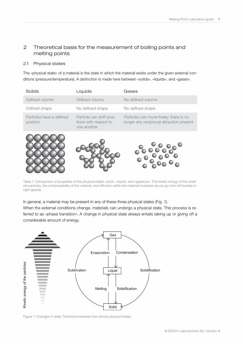
2.1 Physical states
The «physical state» of a material is the state in which the material exists under the given external con-
ditions (pressure/temperature). A distinction is made here between «solids», «liquids», and «gases».
Solids Liquids Gases
Defined volume Defined volume No defined volume
Defined shape No defined shape No defined shape
Particles have a defined position
Particle can shift posi-tions with respect to one another
Particles can move freely; there is no longer any reciprocal attraction present
Table 1: Comparison of properties of the physical states «solid», «liquid», and «gaseous». The kinetic energy of the small-est particles, the compressibility of the material, and diffusion within the material increases as you go from left (solids) to right (gases).
In general, a material may be present in any of these three physical states (Fig. 1).
When the external conditions change, materials can undergo a physical state. This process is re-
ferred to as «phase transition». A change in physical state always entails taking up or giving off a
considerable amount of energy.
Figure 1: Changes in state: Transitions between the various physical states.
2 Theoretical basis for the measurement of boiling points and melting points
8 Melting Point Laboratory guide
© BÜCHI Labortechnik AG | Version A
Most materials are crystalline when solid, i.e., in that state, their smallest particles (atoms, mol-ecules, or ions) form an orderly, 3-dimensional arrangement – a crystalline lattice. The stability of the lattice depends not only on how strong the forces between two components of the grid are between themselves, but also on how uniformly these forces act in all directions in space. In addition to crystalline solids, there exist also amorphous solids, whose particles are in a random arrangement in the solid state. Glass, resin, and many synthetic plastics are examples of amor-phous materials.
2.2 Phase transitions
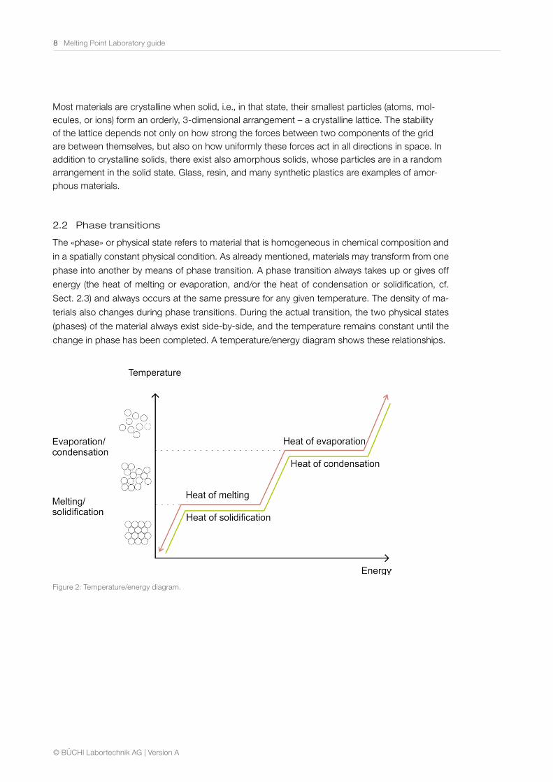
The «phase» or physical state refers to material that is homogeneous in chemical composition and
in a spatially constant physical condition. As already mentioned, materials may transform from one
phase into another by means of phase transition. A phase transition always takes up or gives off
energy (the heat of melting or evaporation, and/or the heat of condensation or solidification, cf.
Sect. 2.3) and always occurs at the same pressure for any given temperature. The density of ma-
terials also changes during phase transitions. During the actual transition, the two physical states
(phases) of the material always exist side-by-side, and the temperature remains constant until the
change in phase has been completed. A temperature/energy diagram shows these relationships.
Figure 2: Temperature/energy diagram.
Melting Point Laboratory guide 9
© BÜCHI Labortechnik AG | Version A
2.2.1 Phase diagrams for 1-material systems (state diagrams)
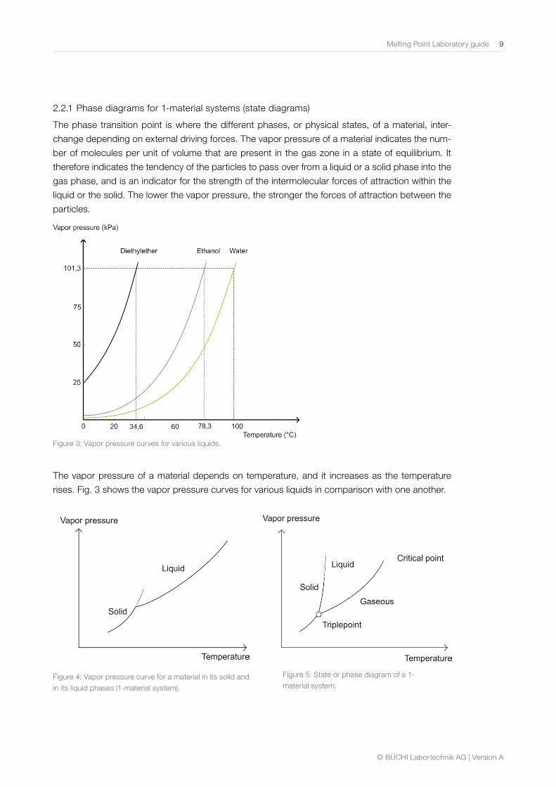
The phase transition point is where the different phases, or physical states, of a material, inter-
change depending on external driving forces. The vapor pressure of a material indicates the num-
ber of molecules per unit of volume that are present in the gas zone in a state of equilibrium. It
therefore indicates the tendency of the particles to pass over from a liquid or a solid phase into the
gas phase, and is an indicator for the strength of the intermolecular forces of attraction within the
liquid or the solid. The lower the vapor pressure, the stronger the forces of attraction between the
particles.
Figure 3: Vapor pressure curves for various liquids.
The vapor pressure of a material depends on temperature, and it increases as the temperature
rises. Fig. 3 shows the vapor pressure curves for various liquids in comparison with one another.
Figure 4: Vapor pressure curve for a material in its solid and
in its liquid phases (1-material system).
Figure 5: State or phase diagram of a 1-
material system.
10 Melting Point Laboratory guide
© BÜCHI Labortechnik AG | Version A
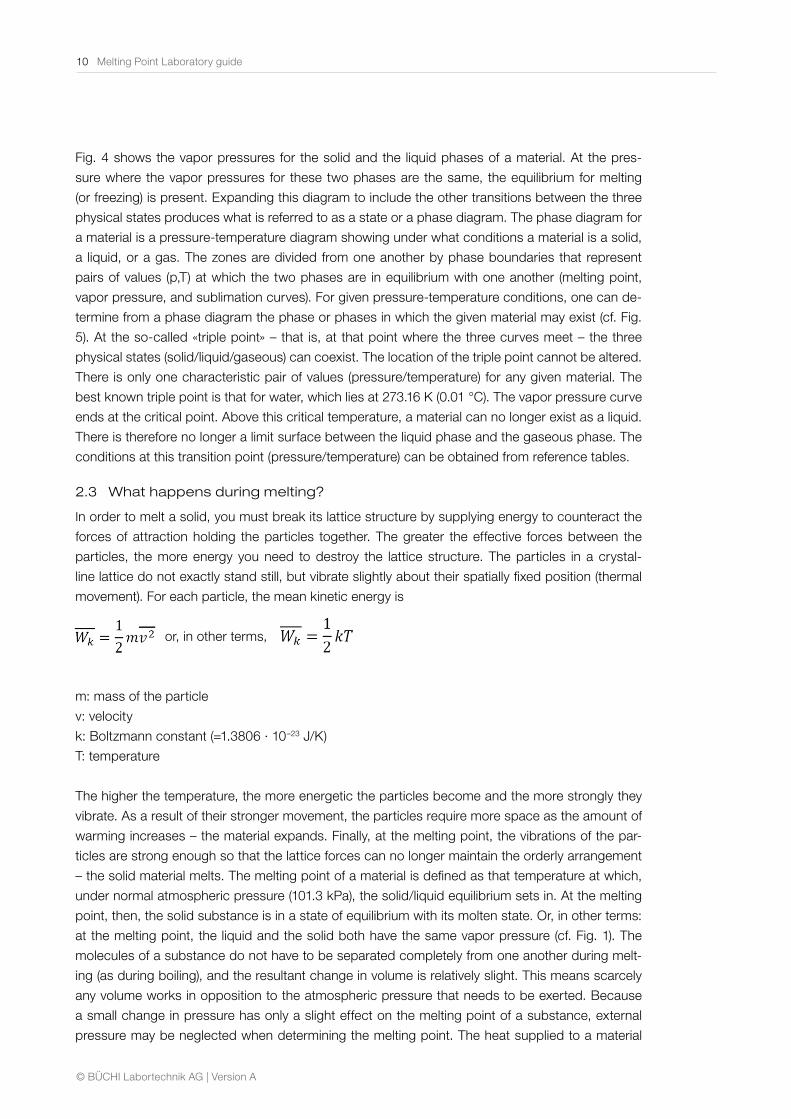
Fig. 4 shows the vapor pressures for the solid and the liquid phases of a material. At the pres-
sure where the vapor pressures for these two phases are the same, the equilibrium for melting
(or freezing) is present. Expanding this diagram to include the other transitions between the three
physical states produces what is referred to as a state or a phase diagram. The phase diagram for
a material is a pressure-temperature diagram showing under what conditions a material is a solid,
a liquid, or a gas. The zones are divided from one another by phase boundaries that represent
pairs of values (p,T) at which the two phases are in equilibrium with one another (melting point,
vapor pressure, and sublimation curves). For given pressure-temperature conditions, one can de-
termine from a phase diagram the phase or phases in which the given material may exist (cf. Fig.
5). At the so-called «triple point» – that is, at that point where the three curves meet – the three
physical states (solid/liquid/gaseous) can coexist. The location of the triple point cannot be altered.
There is only one characteristic pair of values (pressure/temperature) for any given material. The
best known triple point is that for water, which lies at 273.16 K (0.01 °C). The vapor pressure curve
ends at the critical point. Above this critical temperature, a material can no longer exist as a liquid.
There is therefore no longer a limit surface between the liquid phase and the gaseous phase. The
conditions at this transition point (pressure/temperature) can be obtained from reference tables.
2.3 What happens during melting?
In order to melt a solid, you must break its lattice structure by supplying energy to counteract the
forces of attraction holding the particles together. The greater the effective forces between the
particles, the more energy you need to destroy the lattice structure. The particles in a crystal-
line lattice do not exactly stand still, but vibrate slightly about their spatially fixed position (thermal
movement). For each particle, the mean kinetic energy is
m: mass of the particle
v: velocity
k: Boltzmann constant (=1.3806 · 10–23 J/K)
T: temperature
The higher the temperature, the more energetic the particles become and the more strongly they
vibrate. As a result of their stronger movement, the particles require more space as the amount of
warming increases – the material expands. Finally, at the melting point, the vibrations of the par-
ticles are strong enough so that the lattice forces can no longer maintain the orderly arrangement
– the solid material melts. The melting point of a material is defined as that temperature at which,
under normal atmospheric pressure (101.3 kPa), the solid/liquid equilibrium sets in. At the melting
point, then, the solid substance is in a state of equilibrium with its molten state. Or, in other terms:
at the melting point, the liquid and the solid both have the same vapor pressure (cf. Fig. 1). The
molecules of a substance do not have to be separated completely from one another during melt-
ing (as during boiling), and the resultant change in volume is relatively slight. This means scarcely
any volume works in opposition to the atmospheric pressure that needs to be exerted. Because
a small change in pressure has only a slight effect on the melting point of a substance, external
pressure may be neglected when determining the melting point. The heat supplied to a material
or, in other terms,
© BÜCHI Labortechnik AG | Version A
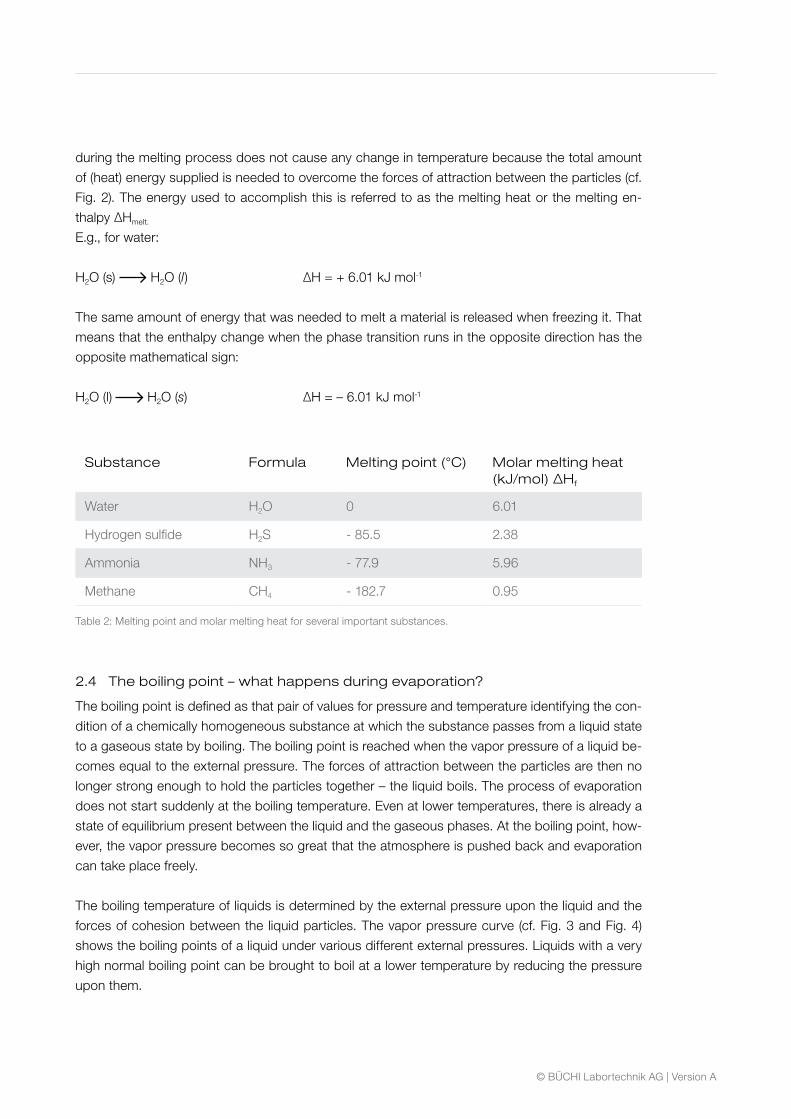
during the melting process does not cause any change in temperature because the total amount
of (heat) energy supplied is needed to overcome the forces of attraction between the particles (cf.
Fig. 2). The energy used to accomplish this is referred to as the melting heat or the melting en-
thalpy ΔHmelt.
E.g., for water:
H2O (s) H2O (l) ΔH = + 6.01 kJ mol-1
The same amount of energy that was needed to melt a material is released when freezing it. That
means that the enthalpy change when the phase transition runs in the opposite direction has the
opposite mathematical sign:
H2O (l) H2O (s) ΔH = – 6.01 kJ mol-1
Substance Formula Melting point (°C) Molar melting heat(kJ/mol) ΔHf
Water H2O 0 6.01
Hydrogen sulfide H2S - 85.5 2.38
Ammonia NH3 - 77.9 5.96
Methane CH4 - 182.7 0.95
Table 2: Melting point and molar melting heat for several important substances.
2.4 The boiling point – what happens during evaporation?
The boiling point is defined as that pair of values for pressure and temperature identifying the con-
dition of a chemically homogeneous substance at which the substance passes from a liquid state
to a gaseous state by boiling. The boiling point is reached when the vapor pressure of a liquid be-
comes equal to the external pressure. The forces of attraction between the particles are then no
longer strong enough to hold the particles together – the liquid boils. The process of evaporation
does not start suddenly at the boiling temperature. Even at lower temperatures, there is already a
state of equilibrium present between the liquid and the gaseous phases. At the boiling point, how-
ever, the vapor pressure becomes so great that the atmosphere is pushed back and evaporation
can take place freely.
The boiling temperature of liquids is determined by the external pressure upon the liquid and the
forces of cohesion between the liquid particles. The vapor pressure curve (cf. Fig. 3 and Fig. 4)
shows the boiling points of a liquid under various different external pressures. Liquids with a very
high normal boiling point can be brought to boil at a lower temperature by reducing the pressure
upon them.
12 Melting Point Laboratory guide
© BÜCHI Labortechnik AG | Version A
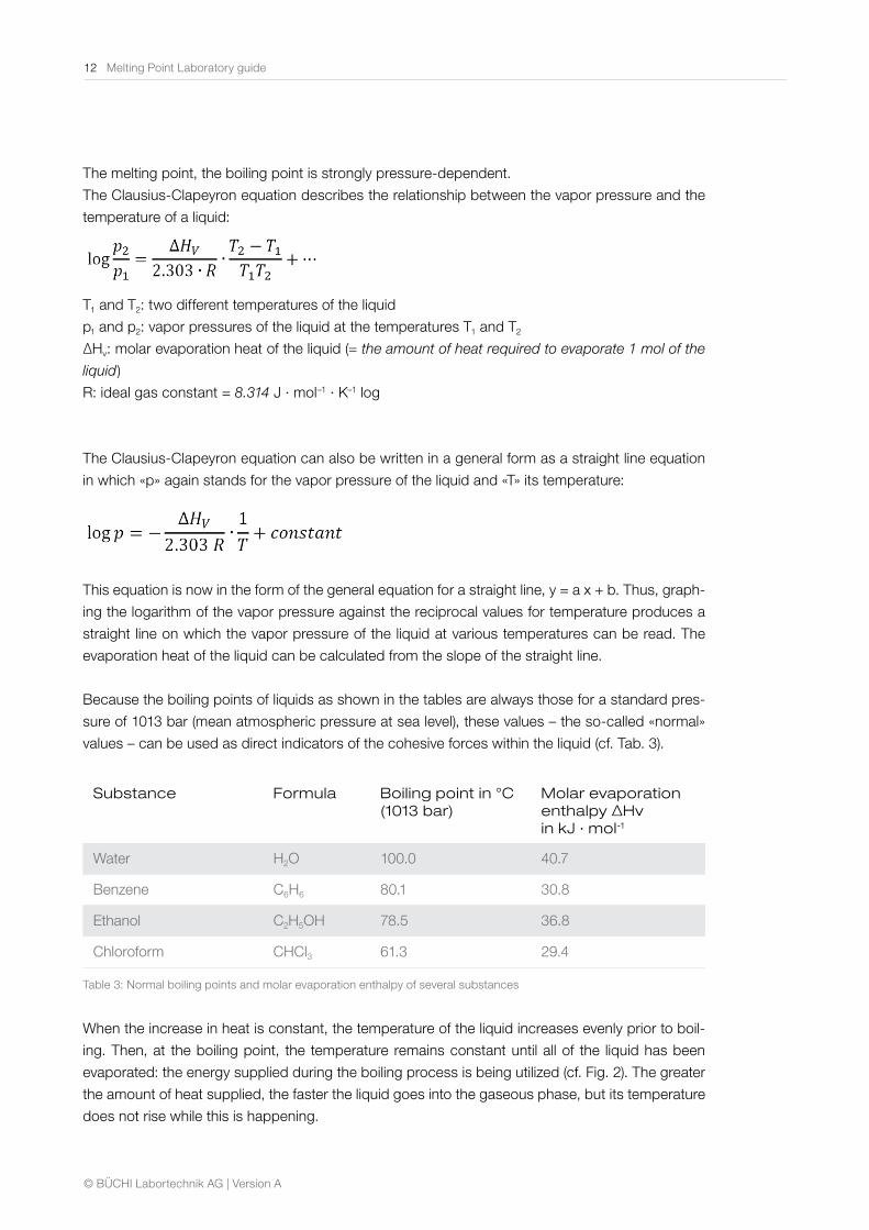
The melting point, the boiling point is strongly pressure-dependent.
The Clausius-Clapeyron equation describes the relationship between the vapor pressure and the
temperature of a liquid:
T1 and T2: two different temperatures of the liquid
p1 and p2: vapor pressures of the liquid at the temperatures T1 and T2
ΔHv: molar evaporation heat of the liquid (= the amount of heat required to evaporate 1 mol of the
liquid)
R: ideal gas constant = 8.314 J · mol–1 · K–1 log
The Clausius-Clapeyron equation can also be written in a general form as a straight line equation
in which «p» again stands for the vapor pressure of the liquid and «T» its temperature:
This equation is now in the form of the general equation for a straight line, y = a x + b. Thus, graph-
ing the logarithm of the vapor pressure against the reciprocal values for temperature produces a
straight line on which the vapor pressure of the liquid at various temperatures can be read. The
evaporation heat of the liquid can be calculated from the slope of the straight line.
Because the boiling points of liquids as shown in the tables are always those for a standard pres-
sure of 1013 bar (mean atmospheric pressure at sea level), these values – the so-called «normal»
values – can be used as direct indicators of the cohesive forces within the liquid (cf. Tab. 3).
Substance Formula Boiling point in °C (1013 bar)
Molar evaporation enthalpy ΔHv in kJ · mol-1
Water H2O 100.0 40.7
Benzene C6H6 80.1 30.8
Ethanol C2H5OH 78.5 36.8
Chloroform CHCl3 61.3 29.4
Table 3: Normal boiling points and molar evaporation enthalpy of several substances
When the increase in heat is constant, the temperature of the liquid increases evenly prior to boil-
ing. Then, at the boiling point, the temperature remains constant until all of the liquid has been
evaporated: the energy supplied during the boiling process is being utilized (cf. Fig. 2). The greater
the amount of heat supplied, the faster the liquid goes into the gaseous phase, but its temperature
does not rise while this is happening.
Melting Point Laboratory guide 13
© BÜCHI Labortechnik AG | Version A
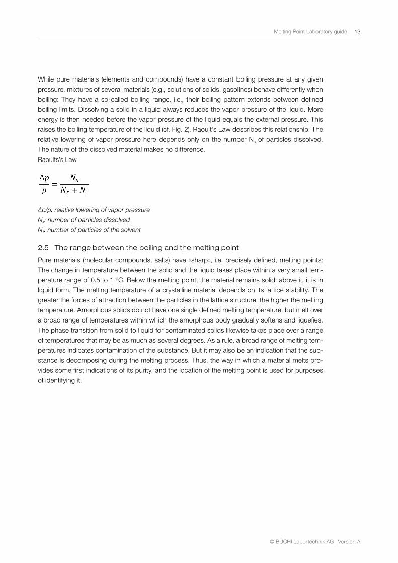
While pure materials (elements and compounds) have a constant boiling pressure at any given
pressure, mixtures of several materials (e.g., solutions of solids, gasolines) behave differently when
boiling: They have a so-called boiling range, i.e., their boiling pattern extends between defined
boiling limits. Dissolving a solid in a liquid always reduces the vapor pressure of the liquid. More
energy is then needed before the vapor pressure of the liquid equals the external pressure. This
raises the boiling temperature of the liquid (cf. Fig. 2). Raoult’s Law describes this relationship. The
relative lowering of vapor pressure here depends only on the number Ns of particles dissolved.
The nature of the dissolved material makes no difference.
Raoults’s Law
∆p/p: relative lowering of vapor pressure
Ns: number of particles dissolved
N1: number of particles of the solvent
2.5 The range between the boiling and the melting point
Pure materials (molecular compounds, salts) have «sharp», i.e. precisely defined, melting points:
The change in temperature between the solid and the liquid takes place within a very small tem-
perature range of 0.5 to 1 °C. Below the melting point, the material remains solid; above it, it is in
liquid form. The melting temperature of a crystalline material depends on its lattice stability. The
greater the forces of attraction between the particles in the lattice structure, the higher the melting
temperature. Amorphous solids do not have one single defined melting temperature, but melt over
a broad range of temperatures within which the amorphous body gradually softens and liquefies.
The phase transition from solid to liquid for contaminated solids likewise takes place over a range
of temperatures that may be as much as several degrees. As a rule, a broad range of melting tem-
peratures indicates contamination of the substance. But it may also be an indication that the sub-
stance is decomposing during the melting process. Thus, the way in which a material melts pro-
vides some first indications of its purity, and the location of the melting point is used for purposes
of identifying it.
14 Melting Point Laboratory guide
© BÜCHI Labortechnik AG | Version A
2.6 Melting point depression and the mixed melting point
2.6.1 Melting point depression
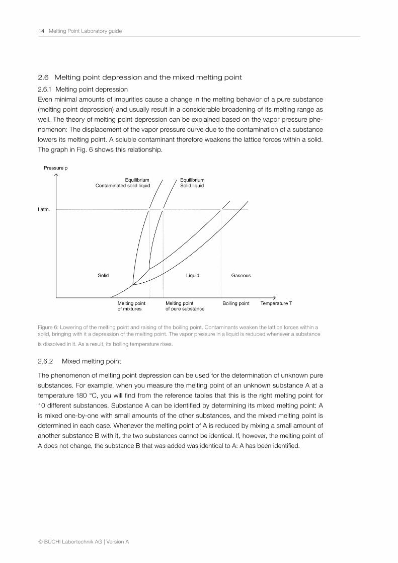
Even minimal amounts of impurities cause a change in the melting behavior of a pure substance
(melting point depression) and usually result in a considerable broadening of its melting range as
well. The theory of melting point depression can be explained based on the vapor pressure phe-
nomenon: The displacement of the vapor pressure curve due to the contamination of a substance
lowers its melting point. A soluble contaminant therefore weakens the lattice forces within a solid.
The graph in Fig. 6 shows this relationship.
Figure 6: Lowering of the melting point and raising of the boiling point. Contaminants weaken the lattice forces within a solid, bringing with it a depression of the melting point. The vapor pressure in a liquid is reduced whenever a substance
is dissolved in it. As a result, its boiling temperature rises.
2.6.2 Mixed melting point
The phenomenon of melting point depression can be used for the determination of unknown pure
substances. For example, when you measure the melting point of an unknown substance A at a
temperature 180 °C, you will find from the reference tables that this is the right melting point for
10 different substances. Substance A can be identified by determining its mixed melting point: A
is mixed one-by-one with small amounts of the other substances, and the mixed melting point is
determined in each case. Whenever the melting point of A is reduced by mixing a small amount of
another substance B with it, the two substances cannot be identical. If, however, the melting point of
A does not change, the substance B that was added was identical to A: A has been identified.
Melting Point Laboratory guide 15
© BÜCHI Labortechnik AG | Version A
2.6.3 The eutectic point
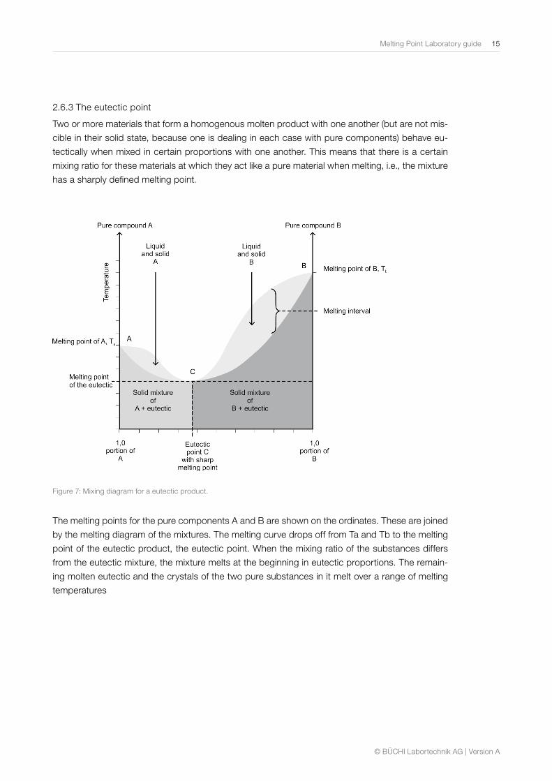
Two or more materials that form a homogenous molten product with one another (but are not mis-
cible in their solid state, because one is dealing in each case with pure components) behave eu-
tectically when mixed in certain proportions with one another. This means that there is a certain
mixing ratio for these materials at which they act like a pure material when melting, i.e., the mixture
has a sharply defined melting point.
Figure 7: Mixing diagram for a eutectic product.
The melting points for the pure components A and B are shown on the ordinates. These are joined
by the melting diagram of the mixtures. The melting curve drops off from Ta and Tb to the melting
point of the eutectic product, the eutectic point. When the mixing ratio of the substances differs
from the eutectic mixture, the mixture melts at the beginning in eutectic proportions. The remain-
ing molten eutectic and the crystals of the two pure substances in it melt over a range of melting
temperatures
16 Melting Point Laboratory guide
© BÜCHI Labortechnik AG | Version A
3 Principles and methods of melting point determination
3.1 Methods of melting point determination
The procedural rules for melting point determination are defined in the pharmacopoeias (Medical
Handbooks/cf. Chap. 5.1). These agree in describing the capillary method as the basic method for
melting point determination. The medical handbooks even explain minimum requirements for the
design of the apparatus and for carrying out the determination. In addition to the capillary method,
the pharmacopoeias also describe other possible methods that may be called upon in special
cases for melting point determination.
3.1.1 Determining the melting point in the capillary tube
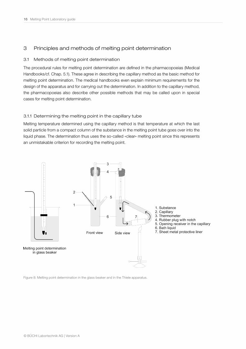
Melting temperature determined using the capillary method is that temperature at which the last
solid particle from a compact column of the substance in the melting point tube goes over into the
liquid phase. The determination thus uses the so-called «clear» melting point since this represents
an unmistakable criterion for recording the melting point.
Figure 8: Melting point determination in the glass beaker and in the Thiele apparatus.
Melting Point Laboratory guide 17
© BÜCHI Labortechnik AG | Version A
The standard capillary method described in the pharmacopoeias starts with a heated liquid bath
equipped with a thermometer for measuring the temperature. A glass capillary tube containing the
substance to be determined is introduced into this liquid in such a way that the substance in the
capillary tube is located close to the mercury reservoir on the thermometer. At the clear melting
point, the temperature reading on thermometer is taken.
The capillary method described in the pharmacopoeias starts from visual detection of the melting
point. More modern instruments for melting point determination enable detection of the melting
point not only in the traditional way, visually, but also automatically (cf. Chapter 4.1.1). In addition
to the capillary method, the medical handbooks also provide another method that can be called
upon «in certain exceptional cases» for determining the melting point – the so-called «open capil-
lary method» (rising tube melting point). This method is of importance mainly for the investigation
of solid greases (e.g., mixtures of various glycerides) because what is observed here on heating
is not really a melting point in the strictest sense of the word, but rather a gradual softening and
liquefying of the substance. Fig. 8 shows two possible instruments that operate using the «bath
method» described in the pharmacopoeias.
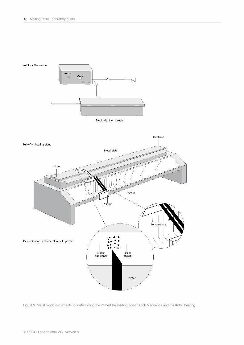
3.1.2 Immediate melting point
Some materials decompose during the melting process or show a tendency toward polymor-
phous modifications. The capillary method is not suitable for use with such substances, which is
why the pharmacopoeia provides for using the flash melting point in such cases. In this method,
the temperature does not affect the substance at all prior to its reaching its melting point. This
method uses a heatable metal block (e.g., of brass) that is heated up evenly. A few crystals of the
substance to be determined are scattered on this block at regular intervals. The first temperature
at which the substance melts immediately on contact with the metal block is read off as T1. The
heating of the block is discontinued, and while it is cooling down, small samples of the substance
are again scattered on the block at regular intervals. T2 is the temperature at which the substance
stops melting immediately on contact with the metal.
The immediate melting point is then obtained from the formula:
Mainly, there are two variants of such a metal block that have worked out well in practice: the rect-
angular Bloc Maquenne that is used predominantly in France, and the metal block of the DAB7
that is commonly used in Germany. The Kofler heating stand is particularly well-suited for series
measurement of the immediate flash point where no special requirements are made with regard to
accuracy of measurement. Fig. 9 shows the various instruments available.
18 Melting Point Laboratory guide
© BÜCHI Labortechnik AG | Version A
Figure 9: Metal block instruments for determining the immediate melting point: Block Maquenne and the Kofler heating
Melting Point Laboratory guide 19
© BÜCHI Labortechnik AG | Version A
3.2 Principles of melting point determination
3.2.1 Melting point determination according to the pharmacopoeia
The instructions for melting point determination in the pharmacopoeias call for an increase of heat
in the «liquid bath» (or in the heating stand) of approximately 1 °C per minute in the range close
to the expected melting temperature. This slow increase of heat and the continual stirring of the
liquid bath are used to ensure that the sample will reach the same temperature as the bath. Nev-
ertheless, in most cases it is difficult to prevent a temperature difference of approximately 1 °C re-
maining between the sample and the liquid bath. In determining the melting point as described in
the pharmacopeia – the temperature on the thermometer at the clear melting point (cf. Chap.3.1.1)
is read. This is not the temperature of the sample, but that of the liquid bath (or the heating stand)
measured at the clear melting point.
Rate of heat rise °C/min Melting point determination, in °C (acc. to the pharmacopeia)
0.2 82.5
0.5 82.8
1 83.3
2 83.6
Table 4: Shows dependence of melting point and rate of heat rise.
When different rates of heat increase are used for determining the melting point of a sample, the
values obtained for the melting point are dependent on the temperature gradient: the quicker the
heat rises, the higher the temperatures are found to be. Table 4 shows this dependency.
What is being measured when determining the melting point is not the effective temperature of
the sample itself but that of the heating bath / heating block. Because the heat transfer from the
bath liquid (or the heating block) to the sample cannot be increased proportionally to rate of heat
increase, the temperature in the bath liquid (or the heating block) rises to a higher level with faster
rates of heat increase than it does with slower rates.
Due to the dependence on the rate of heat increase, measurements taken for melting points are
comparable with one another only if they were taken using the same rates. Any variance from the
rates of heat increase called for in the specifications during the determination of a substance (e.g.,
the instructions in the pharmacopoeia) must be properly documented.
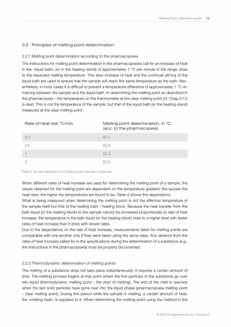
3.2.2 Thermodynamic determination of melting points
The melting of a substance does not take place instantaneously: it requires a certain amount of
time. The melting process begins at that point where the first particles of the substance go over
into liquid (thermodynamic melting point - the start of melting). The end of the melt is reached
when the last solid particles have gone over into the liquid phase (pharmacopoeia melting point
- clear melting point). During this period while the sample is melting, a certain amount of heat,
the «melting heat», is supplied to it. When determining the melting point using the method in the
20 Melting Point Laboratory guide
© BÜCHI Labortechnik AG | Version A
pharmacopeia, the temperature of the liquid in the bath (or of the heating furnace) at the end of
the melting is read. While that temperature depends on the rate of heat increase in the system (cf.
3.2.1), it also neglects a certain difference in temperature between the start and the end of the
melting. In order to obtain the correct melting temperature, it is therefore reasonable to subtract a
thermodynamic correction factor from the temperature detected. This calculates back to the tem-
perature of the sample at the start of melting, so that the value detected then includes practically
no effect arising from the rate of heat rise used.
Rate of heat increase °C/min Melting point detected, in °C (thermodynamically)
0.2 81.9
0.5 81.9
1 82.0
2 81.8
Table 5: Shows thermodynamically detected melting points at various rates of heat increase.
Procedure for calculating the thermodynamic correction factor:
Figure 10: Calculation of the thermodynamic correction factor.
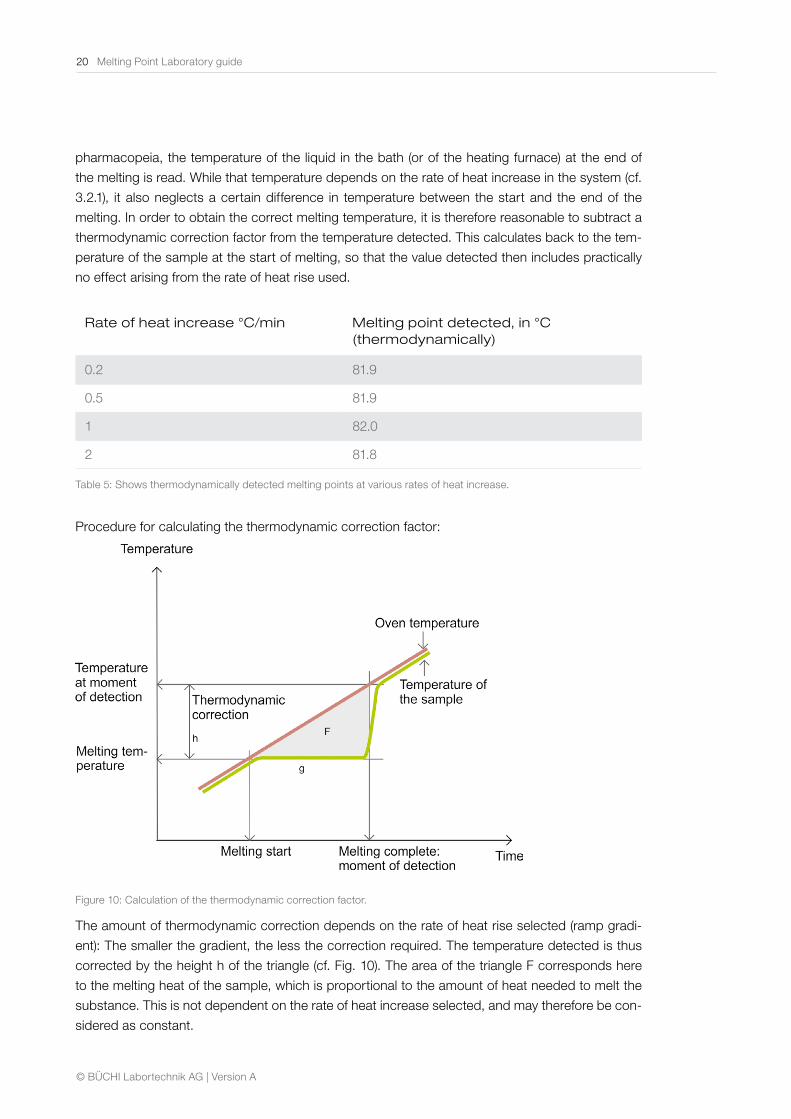
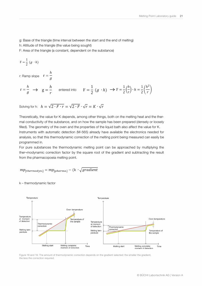
The amount of thermodynamic correction depends on the rate of heat rise selected (ramp gradi-
ent): The smaller the gradient, the less the correction required. The temperature detected is thus
corrected by the height h of the triangle (cf. Fig. 10). The area of the triangle F corresponds here
to the melting heat of the sample, which is proportional to the amount of heat needed to melt the
substance. This is not dependent on the rate of heat increase selected, and may therefore be con-
sidered as constant.
Melting Point Laboratory guide 21
© BÜCHI Labortechnik AG | Version A
g: Base of the triangle (time interval between the start and the end of melting)
h: Altitude of the triangle (the value being sought)
F: Area of the triangle (a constant, dependent on the substance)
entered into
r: Ramp slope
Solving for h:
Theoretically, the value for K depends, among other things, both on the melting heat and the ther-
mal conductivity of the substance, and on how the sample has been prepared (densely or loosely
filled). The geometry of the oven and the properties of the liquid bath also affect the value for K.
Instruments with automatic detection (M-565) already have available the electronics needed for
analysis, so that this thermodynamic correction of the melting point being measured can easily be
programmed in.
For pure substances the thermodynamic melting point can be approached by multiplying the
ther¬modynamic correction factor by the square root of the gradient and subtracting the result
from the pharmacopoeia melting point.
k – thermodynamic factor
Figure 18 and 19: The amount of thermodynamic correction depends on the gradient selected: the smaller the gradient, the less the correction required.
22 Melting Point Laboratory guide
© BÜCHI Labortechnik AG | Version A
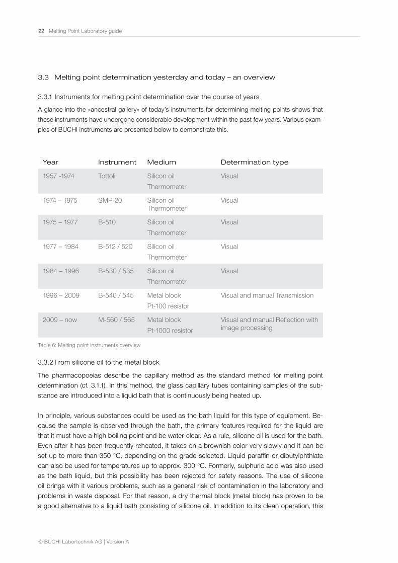
3.3 Melting point determination yesterday and today – an overview
3.3.1 Instruments for melting point determination over the course of years
A glance into the «ancestral gallery» of today’s instruments for determining melting points shows that
these instruments have undergone considerable development within the past few years. Various exam-
ples of BUCHI instruments are presented below to demonstrate this.
Year Instrument Medium Determination type
1957 -1974 Tottoli Silicon oil
Thermometer
Visual
1974 – 1975 SMP-20 Silicon oil Thermometer
Visual
1975 – 1977 B-510 Silicon oil
Thermometer
Visual
1977 – 1984 B-512 / 520 Silicon oil
Thermometer
Visual
1984 – 1996 B-530 / 535 Silicon oil
Thermometer
Visual
1996 – 2009 B-540 / 545 Metal block
Pt-100 resistor
Visual and manual Transmission
2009 – now M-560 / 565 Metal block
Pt-1000 resistor
Visual and manual Reflection with image processing
Table 6: Melting point instruments overview
3.3.2 From silicone oil to the metal block
The pharmacopoeias describe the capillary method as the standard method for melting point
determination (cf. 3.1.1). In this method, the glass capillary tubes containing samples of the sub-
stance are introduced into a liquid bath that is continuously being heated up.
In principle, various substances could be used as the bath liquid for this type of equipment. Be-
cause the sample is observed through the bath, the primary features required for the liquid are
that it must have a high boiling point and be water-clear. As a rule, silicone oil is used for the bath.
Even after it has been frequently reheated, it takes on a brownish color very slowly and it can be
set up to more than 350 °C, depending on the grade selected. Liquid paraffin or dibutylphthlate
can also be used for temperatures up to approx. 300 °C. Formerly, sulphuric acid was also used
as the bath liquid, but this possibility has been rejected for safety reasons. The use of silicone
oil brings with it various problems, such as a general risk of contamination in the laboratory and
problems in waste disposal. For that reason, a dry thermal block (metal block) has proven to be
a good alternative to a liquid bath consisting of silicone oil. In addition to its clean operation, this

Melting Point Laboratory guide 23
© BÜCHI Labortechnik AG | Version A
block also offers the possibility of detecting the melting point automatically. In addition to the elimi-
nation of the bath liquid, another advantage of a metal block instrument is that it operates without
a mercury thermometer. Instead of the traditional thermometer, a built-in Pt-1000 resistor is used
to measure the temperatures.
24 Melting Point Laboratory guide
© BÜCHI Labortechnik AG | Version A
4 Melting point determination using the BUCHI M-565
The BUCHI Melting Point M-565 is used to determine melting temperatures and ranges and boil-
ing points from room temperature up to 400 °C. Unlike conventional instruments, this instrument
combines automatic and visual methods for melting point determination. Values can be detected
automatically, and when necessary, the user can perform visual determination of immediate melt-
ing points.
The BUCHI M-565 offers a possibility for performing determinations on three different samples at
the same time. In addition to determination of the melting point, it can also carry out one measure-
ment of boiling point. The boiling point is determined here automatic or visually (cf. Chapter 4.5).
4.1 Operating principle of the BUCHI M-565 instrument
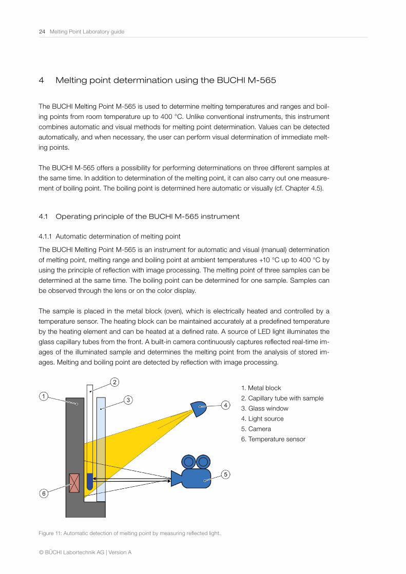
4.1.1 Automatic determination of melting point
The BUCHI Melting Point M-565 is an instrument for automatic and visual (manual) determination
of melting point, melting range and boiling point at ambient temperatures +10 °C up to 400 °C by
using the principle of reflection with image processing. The melting point of three samples can be
determined at the same time. The boiling point can be determined for one sample. Samples can
be observed through the lens or on the color display.
The sample is placed in the metal block (oven), which is electrically heated and controlled by a
temperature sensor. The heating block can be maintained accurately at a predefined temperature
by the heating element and can be heated at a defined rate. A source of LED light illuminates the
glass capillary tubes from the front. A built-in camera continuously captures reflected real-time im-
ages of the illuminated sample and determines the melting point from the analysis of stored im-
ages. Melting and boiling point are detected by reflection with image processing.
Figure 11: Automatic detection of melting point by measuring reflected light.
1. Metal block
2. Capillary tube with sample
3. Glass window
4. Light source
5. Camera
6. Temperature sensor
Melting Point Laboratory guide 25
© BÜCHI Labortechnik AG | Version A
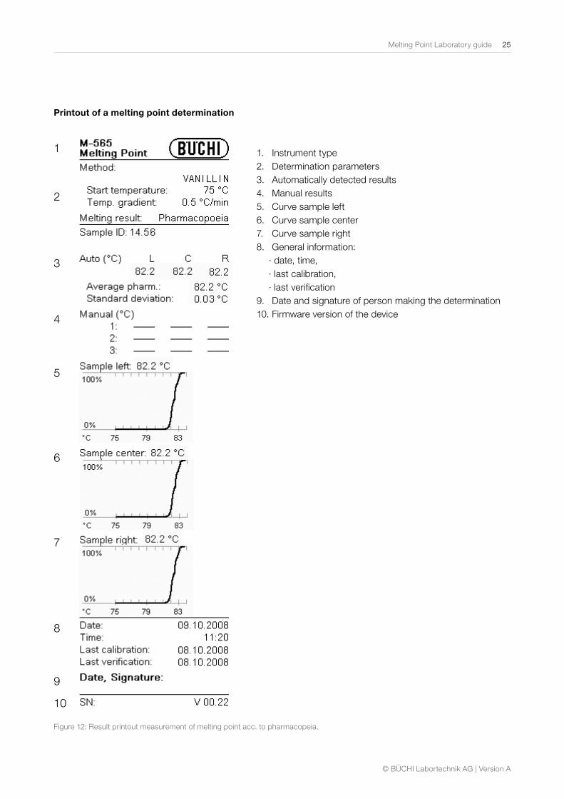
Printout of a melting point determination
1. Instrument type 2. Determination parameters 3. Automatically detected results 4. Manual results 5. Curve sample left 6. Curve sample center 7. Curve sample right 8. General information:
∙ date, time, ∙ last calibration, ∙ last verification
9. Date and signature of person making the determination 10. Firmware version of the device
1
2
3
4
5
6
7
8
9
10
Figure 12: Result printout measurement of melting point acc. to pharmacopeia.
26 Melting Point Laboratory guide
© BÜCHI Labortechnik AG | Version A
4.1.2 Metal heating block
Since a heatable block is absolutely required for automatic detection of the melting point, a metal
heating block in the BUCHI B-545 and M-565 replaces the silicone oil bath used in earlier ap-
paratus (cf. Chapter 3.3.2). This enables exceptionally quick heat-up and cool-down times, and
the samples can be heated to clearly higher temperatures. The heating block method conforms
to the current pharmacopoeia, and has the advantage that no waste silicone oil need to be dis-
posed of. In addition, by replacing the traditional liquid bath with a metal heating block it has be-
come possible to determine the melting point automatically. Chapter 3.2 explains the differences
between thermodynamic determination of the melting point and recording the melting point ac-
cording to pharmacopoeia. In its standard configuration, the BUCHI M-565 supplies thermody-
namically corrected values of the melting point. Two other measurement modes, without cor-
rection, are available to the customers: range mode and pharmacopeia mode. In the second
mentioned mode, the measured values correspond to the oven temperature at the melting point.
Due to the introduction of the dry heating block, the mercury thermometer has been replaced by
a built-in platinum resistor which takes over the digital measurement of the temperature.
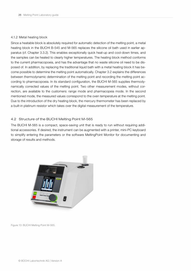
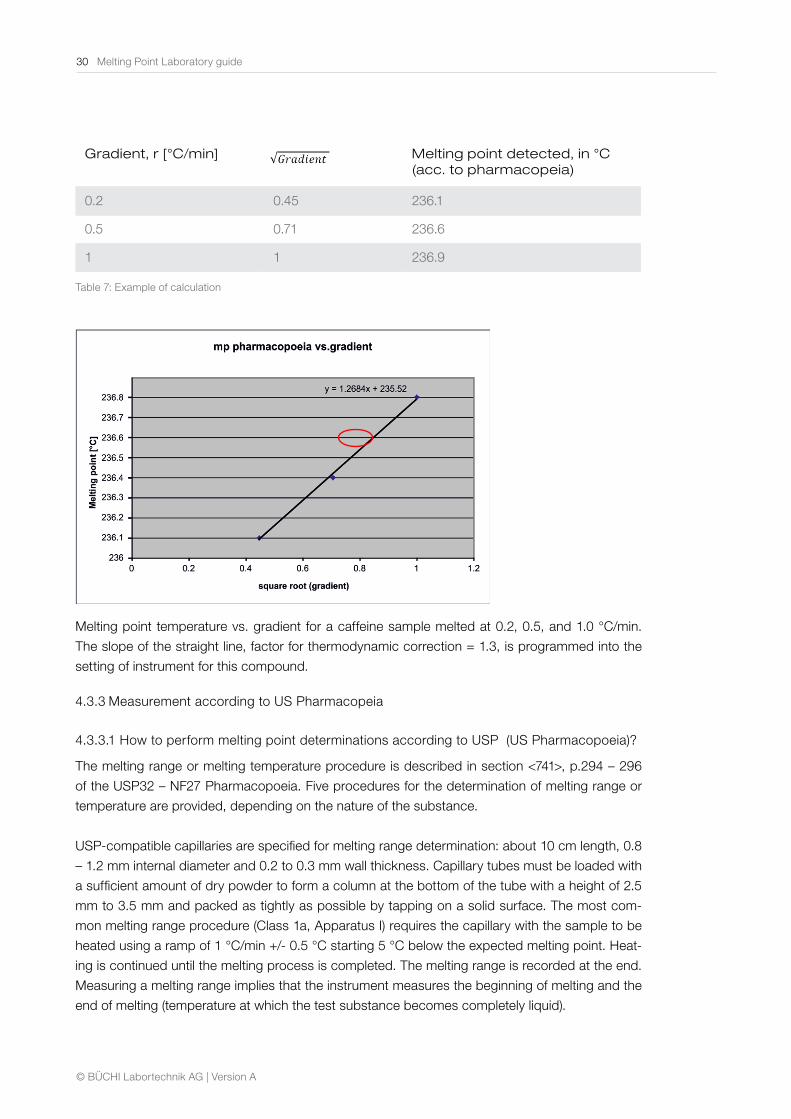
4.2 Structure of the BUCHI Melting Point M-565
The BUCHI M-565 is a compact, space-saving unit that is ready to run without requiring addi-
tional accessories. If desired, the instrument can be augmented with a printer, mini-PC keyboard
to simplify entering the parameters or the software MeltingPoint Monitor for documenting and
storage of results and methods.
Figure 13: BUCHI Melting Point M-565.
Melting Point Laboratory guide 27
© BÜCHI Labortechnik AG | Version A
The Melting Point M-565 instrument has a front panel with large high resolution color display
which allows observing the sample on the color display. A large magnifying lens (2.5 times) on
the front of the instrument enables comfortable observation of the samples during the process of
melting or boiling (cf. Figure 13). Video of the determination allows the review of each measure-
ment and the variable speed playback allows analyzing the measurement after the run. The up-
per section of the oven is made of ceramic and includes the blocks for holding the glass capillaries
(one for detection of the boiling point, and three for determining the melting point). These can be
seen at the top of the instrument. The metal heating block with electrical heater is located below
this ceramic unit.
4.3 Melting point determination procedure with the BUCHI M-565
4.3.1 Sample preparation
The sample being investigated must be fully dry, homogeneous, and in powdered form. Moist
samples must be dried first (the pharmacopoeias prescribe that the substance needs to be dried
in a vacuum for 24 hours over silica gel R). Coarse crystalline and non-homogeneous samples are
finely ground in a mortar.
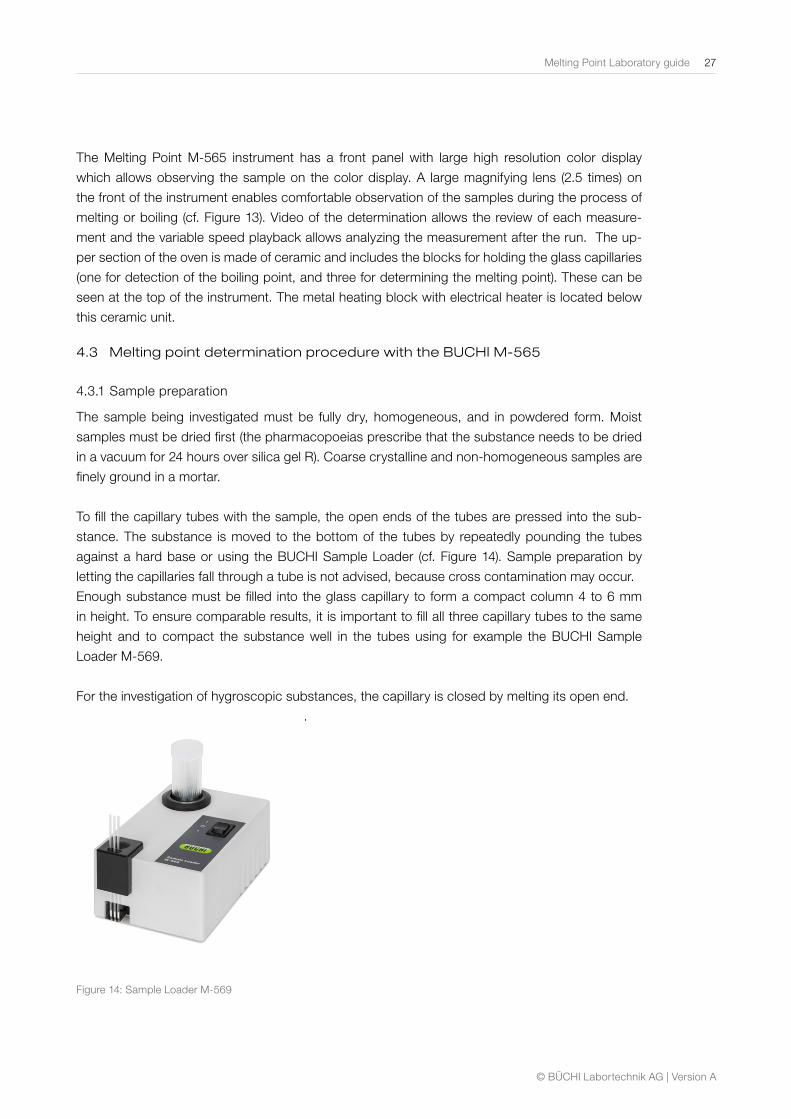
To fill the capillary tubes with the sample, the open ends of the tubes are pressed into the sub-
stance. The substance is moved to the bottom of the tubes by repeatedly pounding the tubes
against a hard base or using the BUCHI Sample Loader (cf. Figure 14). Sample preparation by
letting the capillaries fall through a tube is not advised, because cross contamination may occur.
Enough substance must be filled into the glass capillary to form a compact column 4 to 6 mm
in height. To ensure comparable results, it is important to fill all three capillary tubes to the same
height and to compact the substance well in the tubes using for example the BUCHI Sample
Loader M-569.
For the investigation of hygroscopic substances, the capillary is closed by melting its open end.
.
Figure 14: Sample Loader M-569
28 Melting Point Laboratory guide
© BÜCHI Labortechnik AG | Version A
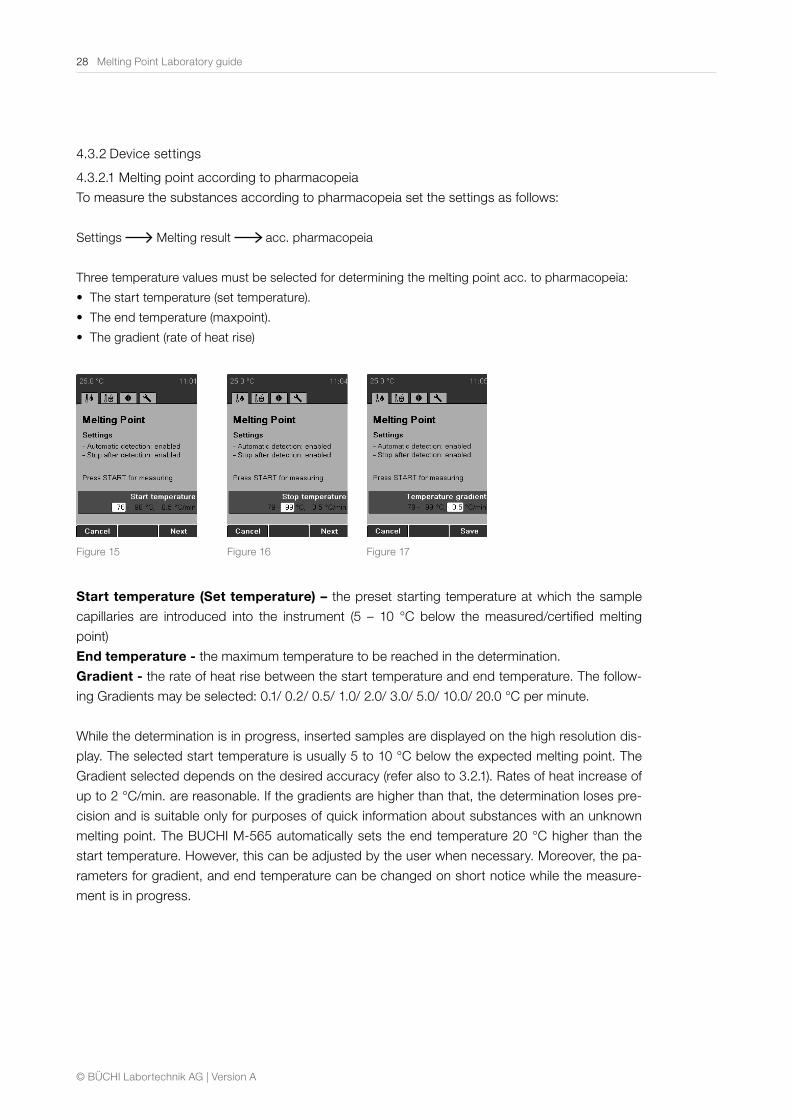
4.3.2 Device settings
4.3.2.1 Melting point according to pharmacopeia
To measure the substances according to pharmacopeia set the settings as follows:
Settings Melting result acc. pharmacopeia
Three temperature values must be selected for determining the melting point acc. to pharmacopeia:
• The start temperature (set temperature).
• The end temperature (maxpoint).
• The gradient (rate of heat rise)
Figure 15 Figure 16 Figure 17
Start temperature (Set temperature) – the preset starting temperature at which the sample
capillaries are introduced into the instrument (5 – 10 °C below the measured/certified melting
point)
End temperature - the maximum temperature to be reached in the determination.
Gradient - the rate of heat rise between the start temperature and end temperature. The follow-
ing Gradients may be selected: 0.1/ 0.2/ 0.5/ 1.0/ 2.0/ 3.0/ 5.0/ 10.0/ 20.0 °C per minute.
While the determination is in progress, inserted samples are displayed on the high resolution dis-
play. The selected start temperature is usually 5 to 10 °C below the expected melting point. The
Gradient selected depends on the desired accuracy (refer also to 3.2.1). Rates of heat increase of
up to 2 °C/min. are reasonable. If the gradients are higher than that, the determination loses pre-
cision and is suitable only for purposes of quick information about substances with an unknown
melting point. The BUCHI M-565 automatically sets the end temperature 20 °C higher than the
start temperature. However, this can be adjusted by the user when necessary. Moreover, the pa-
rameters for gradient, and end temperature can be changed on short notice while the measure-
ment is in progress.
Melting Point Laboratory guide 29
© BÜCHI Labortechnik AG | Version A
4.3.2.2 Melting range
To measure the melting range of the substances set the settings as follows:
Settings Melting result range
Four values must be selected for determining the melting point with the BUCHI M-565: ∙ The start temperature (set temperature). ∙ The end temperature (maxpoint). ∙ The gradient (rate of heat rise). ∙ The threshold
Start temperature (Set temperature) – the preset starting temperature at which the sample
capillaries are introduced into the instrument (5 – 10 °C below the measured/certified melting
point)
End temperature - the maximum temperature to be reached in the determination.
Gradient - the rate of heat rise between the start temperature and end temperature.
The following Gradients may be selected: 0.1/ 0.2/ 0.5/ 1.0/ 2.0/ 3.0/ 5.0/ 10.0/ 20.0 °C per minute.
Threshold – the start of the melting process at that point where the first particle of the substance
goes over into liquid (the start of melting point). The default value is set to 15 %. This value can be
used for 80 % of substances. If the beginning of the melting range differs from that observed, in-
crease or decrease this value.
4.3.2.3 Thermodynamic melting point
Three temperature values must be selected for determining the thermodynamic melting point:
∙ The start temperature (set temperature). ∙ The end temperature (maxpoint). ∙ The Gradient (rate of heat rise).
Start temperature (Set temperature) – the preset starting temperature at which the sample capil-
laries are introduced into the instrument (5 – 10 °C below the measured/certified melting point)
End temperature - the maximum temperature to be reached in the determination.
Gradient - the rate of heat rise between the start temperature and end temperature. The following
Gradients may be selected: 0.1/ 0.2/ 0.5/ 1.0/ 2.0/ 3.0/ 5.0/ 10.0/ 20.0 °C per minute.
To measure the thermodynamic melting point of the substances set the settings as follows:
Settings Melting result thermodynamic
If needed adjust the thermodynamic factor (standard 1.5)
In order to obtain a thermodynamic melting point result within the accuracy of the unit, the following
steps are advised:
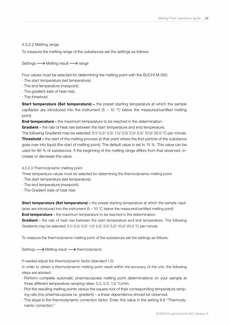
∙ Perform complete automatic pharmacopoeia melting point determinations on your sample at three different temperature ramping rates: 0.2, 0.5, 1.0 °C/min.
∙ Plot the resulting melting points versus the square root of their corresponding temperature ramp-ing rate (mp pharmacopoeia vs. gradient) – a linear dependence should be observed.
∙ The slope is the thermodynamic correction factor. Enter this value in the setting 6.6 “Thermody-namic correction.”
30 Melting Point Laboratory guide
© BÜCHI Labortechnik AG | Version A
Gradient, r [°C/min] Melting point detected, in °C (acc. to pharmacopeia)
0.2 0.45 236.1
0.5 0.71 236.6
1 1 236.9
Table 7: Example of calculation
Melting point temperature vs. gradient for a caffeine sample melted at 0.2, 0.5, and 1.0 °C/min.
The slope of the straight line, factor for thermodynamic correction = 1.3, is programmed into the
setting of instrument for this compound.
4.3.3 Measurement according to US Pharmacopeia
4.3.3.1 How to perform melting point determinations according to USP (US Pharmacopoeia)?
The melting range or melting temperature procedure is described in section <741>, p.294 – 296
of the USP32 – NF27 Pharmacopoeia. Five procedures for the determination of melting range or
temperature are provided, depending on the nature of the substance.
USP-compatible capillaries are specified for melting range determination: about 10 cm length, 0.8
– 1.2 mm internal diameter and 0.2 to 0.3 mm wall thickness. Capillary tubes must be loaded with
a sufficient amount of dry powder to form a column at the bottom of the tube with a height of 2.5
mm to 3.5 mm and packed as tightly as possible by tapping on a solid surface. The most com-
mon melting range procedure (Class 1a, Apparatus I) requires the capillary with the sample to be
heated using a ramp of 1 °C/min +/- 0.5 °C starting 5 °C below the expected melting point. Heat-
ing is continued until the melting process is completed. The melting range is recorded at the end.
Measuring a melting range implies that the instrument measures the beginning of melting and the
end of melting (temperature at which the test substance becomes completely liquid).
Melting Point Laboratory guide 31
© BÜCHI Labortechnik AG | Version A
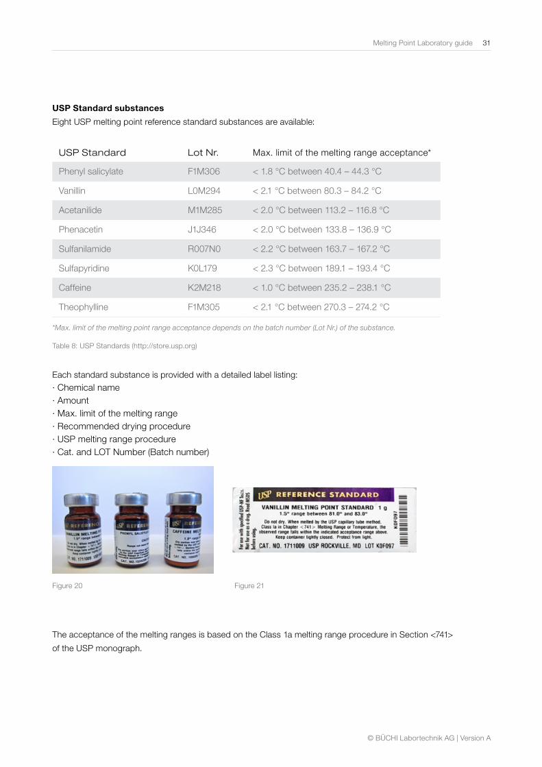
USP Standard substances
Eight USP melting point reference standard substances are available:
USP Standard Lot Nr. Max. limit of the melting range acceptance*
Phenyl salicylate F1M306 < 1.8 °C between 40.4 – 44.3 °C
Vanillin L0M294 < 2.1 °C between 80.3 – 84.2 °C
Acetanilide M1M285 < 2.0 °C between 113.2 – 116.8 °C
Phenacetin J1J346 < 2.0 °C between 133.8 – 136.9 °C
Sulfanilamide R007N0 < 2.2 °C between 163.7 – 167.2 °C
Sulfapyridine K0L179 < 2.3 °C between 189.1 – 193.4 °C
Caffeine K2M218 < 1.0 °C between 235.2 – 238.1 °C
Theophylline F1M305 < 2.1 °C between 270.3 – 274.2 °C
*Max. limit of the melting point range acceptance depends on the batch number (Lot Nr.) of the substance.
Table 8: USP Standards (http://store.usp.org)
Each standard substance is provided with a detailed label listing:
∙ Chemical name ∙ Amount ∙ Max. limit of the melting range ∙ Recommended drying procedure ∙ USP melting range procedure ∙ Cat. and LOT Number (Batch number)
Figure 20 Figure 21
The acceptance of the melting ranges is based on the Class 1a melting range procedure in Section <741>
of the USP monograph.
32 Melting Point Laboratory guide
© BÜCHI Labortechnik AG | Version A
4.3.3.2 How to make a melting point measurement according to USP using the BUCHI M-565
instrument?
To measure USP standard substances set the settings as follows:
Settings Melting result Range
Set the start temperature at approximately 5 °C below its expected melting point and the ramp at
1 °C/min. The threshold should be set at 30 % for USP standards. For the measurement of other
substances, the threshold should be adjusted so that the beginning of melting is the same wheth-
er the detection is manual (observation) or automatic (automatic detection mode must be switched
on).
Load the BUCHI capillary tubes tightly (2.5 mm to 3.5 mm height) using the BUCHI Sample Loader
M-569 or manually by tapping on a solid surface. When the initial temperature is reached, insert
the capillaries and press start.
According to USP the measurement should be observed. However with M-565 the user has the
possibility to measure the melting range automatically (according to section <741>, Apparatus II of
the USP-NF monograph).
Example:
Vanillin (K0F097) 1.5 °C between 81 – 83.0 °C (max. limit of the melting range acceptance)
Start temperature: 76 °C
Temperature range: 1 °C/min
Threshold: 30 %
Auto detection: On
Sample filling height: 3.5 mm
Phenacetin (I0H080) 1.9 °C between 134.0 – 136.6 °C (max. limit of the melting range
acceptance)
Start temperature: 129 °C
Temperature range: 1 °C/min
Threshold: 30 %
Auto detection: On
Sample filling height: 3.5 mm
Caffeine (K0D372) 1.0 °C between 235.6 – 237.5 °C (max. limit of the melting range acceptance)
Start temperature: 231 °C
Temperature range: 1 °C/min
Threshold: 30 %
Auto detection: On
Sample filling height: 3.5 mm
Melting Point Laboratory guide 33
© BÜCHI Labortechnik AG | Version A
Example of results using M-565
USP Standard USP value Result (using M-565)
Vanillin (K0F097) 1.5 °C between 81.0 – 83.0 °C 81.4 – 82.7 °C (1.3 °C)
Phenacetin (I0H080) 1.9 °C between 134.0 – 136.6 °C 134.6 – 135.8 °C (1.2 °C)
Caffeine (K0D372) 1.0 °C between 235.6 – 237.5 °C 236.2 – 237.2 °C (1.0 °C)
Table 9: Example of results using M-565
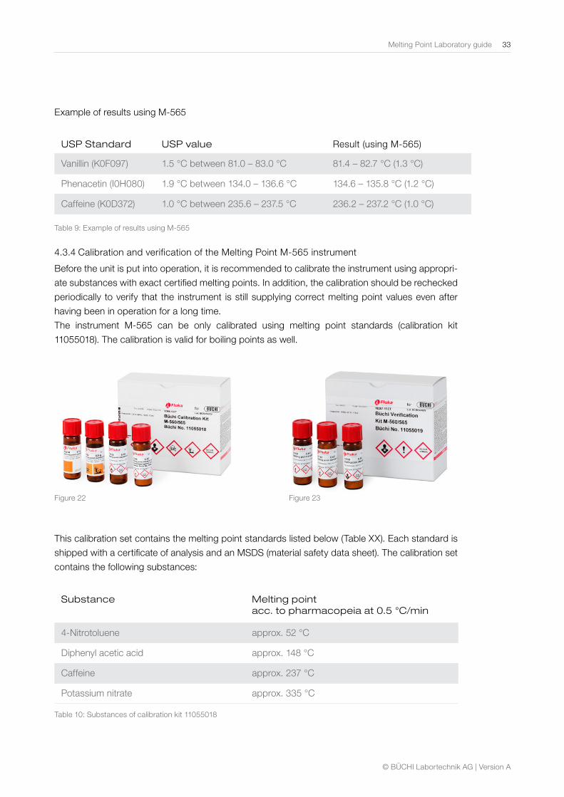
4.3.4 Calibration and verification of the Melting Point M-565 instrument
Before the unit is put into operation, it is recommended to calibrate the instrument using appropri-
ate substances with exact certified melting points. In addition, the calibration should be rechecked
periodically to verify that the instrument is still supplying correct melting point values even after
having been in operation for a long time.
The instrument M-565 can be only calibrated using melting point standards (calibration kit
11055018). The calibration is valid for boiling points as well.
Figure 22
Figure 23
This calibration set contains the melting point standards listed below (Table XX). Each standard is
shipped with a certificate of analysis and an MSDS (material safety data sheet). The calibration set
contains the following substances:
Substance Melting point acc. to pharmacopeia at 0.5 °C/min
4-Nitrotoluene approx. 52 °C
Diphenyl acetic acid approx. 148 °C
Caffeine approx. 237 °C
Potassium nitrate approx. 335 °C
Table 10: Substances of calibration kit 11055018
34 Melting Point Laboratory guide
© BÜCHI Labortechnik AG | Version A
The calibration is intuitive and fully guided. From each substance, a minimum of 6 measurements
have to fulfill a standard deviation of less than +/- 0.2 °C. Otherwise the instrument will not move
on to the next substance. The maximum number of samples for each substance to reach the de-
viation of +/- 0.2 °C is limited to 12 samples. The instrument auto¬matically chooses the best 6
results from the determinations performed.
After a successful calibration is done, it may be checked using the verification kit (11055019). Each
standard of the set contains a certificate of analysis and the MSDS. The verification kit contains
the following substances:
Substance Melting point acc. to pharmacopeia at 0.5 °C/min
Benzil approx. 94 °C
p-Anisic acid approx. 182 °C
Phenolphthalein approx. 261 °C
Table 11: Substances of verification kit 11055019
To verify the calibration, proceed as follows:
Measure all standards, BUCHI recommends using the verification kit (11055019) but it is also pos-
sible to use your internal standards and confirm the verification on the instrument
Please note, that the reference substances must be stored over a desiccant in a desiccator before
being used to check the instrument.
4.4 Flow charts for a melting point determination with the BUCHI M-565
The work flow for a melting point determination depends on whether or not the melting point of
the substance being measured is known. If not, it must first be determined roughly to ascertain
the approximate melting point of the substance. For both cases, the work flows for a melting point
determination (with melting points known/unknown) are presented below in schematic form. Vi-
sual determination of the melting point is shown shaded in gray on the schematics. However for
M-565 the real time visual determination is not necessary. The recorded measurements can be
replayed on the device or using the MeltingPoint Monitor software.
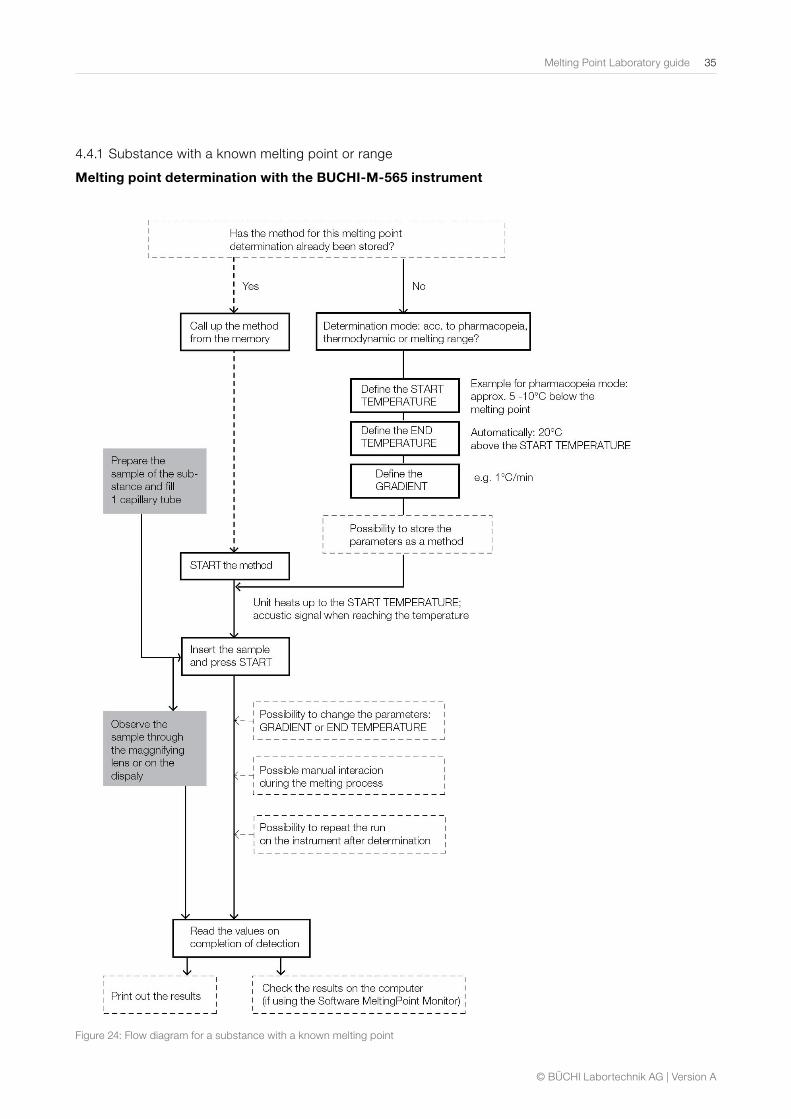
The boxes framed in broken lines describe steps that may be taken or omitted, depending on the
needs of the user.
Melting Point Laboratory guide 35
© BÜCHI Labortechnik AG | Version A
4.4.1 Substance with a known melting point or range
Melting point determination with the BUCHI-M-565 instrument
Figure 24: Flow diagram for a substance with a known melting point
36 Melting Point Laboratory guide
© BÜCHI Labortechnik AG | Version A
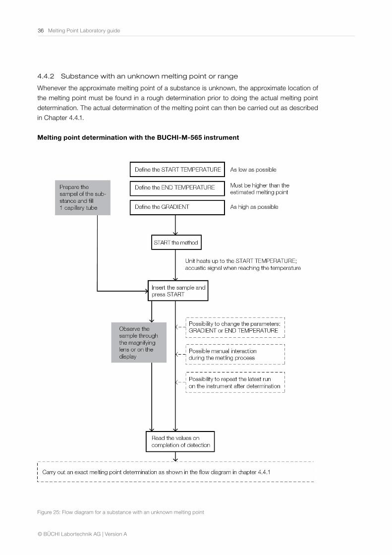
4.4.2 Substance with an unknown melting point or range
Whenever the approximate melting point of a substance is unknown, the approximate location of
the melting point must be found in a rough determination prior to doing the actual melting point
determination. The actual determination of the melting point can then be carried out as described
in Chapter 4.4.1.
Melting point determination with the BUCHI-M-565 instrument
Figure 25: Flow diagram for a substance with an unknown melting point
Melting Point Laboratory guide 37
© BÜCHI Labortechnik AG | Version A
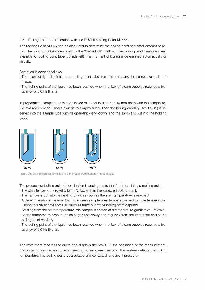
4.5 Boiling point determination with the BUCHI Melting Point M-565
The Melting Point M-565 can be also used to determine the boiling point of a small amount of liq-
uid. The boiling point is determined by the “Siwoloboff” method. The heating block has one insert
available for boiling point tube (outside left). The moment of boiling is determined automatically or
visually.
Detection is done as follows: ∙ The beam of light illuminates the boiling point tube from the front, and the camera records the image.
∙ The boiling point of the liquid has been reached when the flow of steam bubbles reaches a fre-quency of 0.6 Hz [Hertz]
In preparation, sample tube with an inside diameter is filled 5 to 10 mm deep with the sample liq-
uid. We recommend using a syringe to simplify filling. Then the boiling capillary (see fig. 15) is in-
serted into the sample tube with its open/thick end down, and the sample is put into the holding
block.
Figure 26: Boiling point determination: Schematic presentation in three steps.
The process for boiling point determination is analogous to that for determining a melting point: ∙ The start temperature is set 5 to 10 °C lower than the expected boiling point. ∙ The sample is put into the heating block as soon as the start temperature is reached. ∙ A delay time allows the equilibrium between sample oven temperature and sample temperature. During this delay time some air bubbles turns out of the boiling point capillary.
∙ Starting from the start temperature, the sample is heated at a temperature gradient of 1 °C/min. ∙ As the temperature rises, bubbles of gas rise slowly and regularly from the immersed end of the boiling point capillary.
∙ The boiling point of the liquid has been reached when the flow of steam bubbles reaches a fre-quency of 0.6 Hz [Hertz].
The instrument records the curve and displays the result. At the beginning of the measurement,
the current pressure has to be entered to obtain correct results. The system detects the boiling
temperature. The boiling point is calculated and corrected for current pressure.
38 Melting Point Laboratory guide
© BÜCHI Labortechnik AG | Version A
4.6 Data quality – accurate control
Pharmacopoeia
The pharmacopoeia – or «Medicinal Handbook» – is a volume containing official regulations.
It provides data on the nature and storage of medicines and their ingredients, and how they
are to be tested and issued by the pharmacist. In 1964, eight European countries took part
in the convention for preparation of a European medicinal handbook. The objective of this
convention was to achieve an international harmonization of specifications and standards in
the field of pharmaceuticals. National pharmacopoeias have been retained as supplements
to the European pharmacopeia. These have been designed to enable a quick and flexible
introduction of new pharmaceutical standards on a national level. The European Pharma-
copoeias are structured in the same fashion. A first section describes specifications for
equipment, performance, and calibration of the various methods of analysis. For example,
the provisions governing the determination of melting points are also found here in the sub-
chapter «Methods of Physics and Physical Chemistry» (cf. Chapter 3.1). Another chapter is
devoted to reagents (reagents, reference and standard solutions, buffer solutions, titration
substances, etc.). The so-called «monographs» present data on effective agents, adjuvants,
pharmaceutical preparations, and other products. The use of the title or sub-title of a mono-
graph thus implies that the product conforms to the specifications of that monograph.
Avoiding errors in melting point determination
The observance of a few basic rules can help avoid errors in the determination of melt-
ing points. Above all else, the way in which the sample is prepared and the settings of the
equipment have the greatest impact on the accuracy of melting point determinations.
Preparation of samples
Careless preparation of the sample can lead to inexact results, which is why special atten-
tion must be paid to this point. In every case, the substance to be investigated must be dry
and in powdered form. Accordingly, the substance must be dried and finely pulverized in a
mortar beforehand.
The filling of the sample tube may be called the «alpha and omega» of an exact measure-
ment. The substance is moved to the base of the tube and compacted there by pounding
the capillary against a hard base. (This method should be given preference over the use of
a packing wire). In addition to packing, maintaining a given level in the fill is another criterion.
A height of 4 – 6 mm is recommended.
Settings equipment parameters
Along with proper sample preparation, the settings on the instrument are also essential for
the exact determination of a melting point. Correct selection of the start temperature, the
end temperature and the gradient is absolutely necessary to prevent inaccuracies due to a
heat increase in the sample that is incorrect or too fast. A gradient of no more than 0.5 °C
per minute is recommended for an exact determination of the melting point, and the start
temperature selected should lie 5 to 10 °C below the expected melting point.
For substances with a broad melting range, the BUCHI M-565 has the ability to measure
that range. For substances of this type, the function «melting range» should be activated,
since the value measured otherwise is likely to be somewhat of a random measurement.
Melting Point Laboratory guide 39
© BÜCHI Labortechnik AG | Version A
None of the above-mentioned parameters for correct measurement can lead to success unless
the instrument has been calibrated correctly. Regular calibration of the instrument is a basic pre-
requisite for an exact determination of the melting point.
Visual checking
Along with the advantages that automatic melting point determination (e.g., using the BUCHI
M-565) can provide, a high degree of automation which also creates the risk that one will simply
rely on numbers coming from the computer whose accuracy cannot be checked. We therefore
recommend doing visual checks on a random sample basis in addition to the automatic melting
point determinations. Particularly in the case of problematic substances that are tinted or that tend
to bubble. That way, possible errors can be discovered by watching the sample during the melt-
ing process.
GLP (Good Laboratory Practice) regulations
The GLP regulations originated in the pharmaceutical industry in the USA. At that time, various ir-
regularities in the conducting and reporting of laboratory tests led to the establishment of rules to
provide a quality standard for laboratory investigations. The first legal regulations covering GLP
were issued in the USA in 1979. The concept of quality assurance rapidly found increasing ac-
ceptance in the rest of the western world and in Japan, so that the Organization for Economic Co-
operation and Development (OECD) published an internationally coordinated version of the GLP
testing methods in 1981. GLP regulations are of importance mainly in analytical laboratories and
developmental laboratories. All GLP regulations include chapters on the structure of equipment
(principles of design) and the maintenance of laboratory equipment. Instruments used to produce,
measure, or recheck data must be installed, tested, and calibrated/standardized according to pre-
scribed guidelines, and written documentation must be prepared for all inspections performed.
One of the most important principles of the GLP is the requirement for reproducible documenta-
tion of the results of the analyses. The so-called «5-W-Rule» applies here: Who did What, When,
With what, and Why?
GMP (Good Manufacturing Practice) regulations
GMP regulations are applicable in production, and in analysis associated with production. They
were developed at a later date than the GLP regulations, and were focused at producing medici-
nal (pharmaceutical) products in accordance with a quality standard in line with their intended use.
In the USA, these GMP regulations are referred to as cGMP (current Good Manufacturing Prac-
tice) to point out that these guidelines must be adapted constantly in accordance with the current
state of knowledge and changing requirements. For pharmaceutical products, FDA regulations
have set an international standard for GMP regulations. Like the GLP regulations, they put major
emphasis on the design of the equipment used, the measurement and rechecking of data, and
written documentation of all the relevant intervention and checking procedures. Various methods
of qualification and validation are used for this purpose. A detailed description of the various quali-
fication procedures, such as design and installation qualification, functional or performance qualifi-
cation, or the validation of analytical processes and procedures, would go beyond the scope dealt
with here, and has been treated extensively in the technical literature of the field.
40 Melting Point Laboratory guide
© BÜCHI Labortechnik AG | Version A
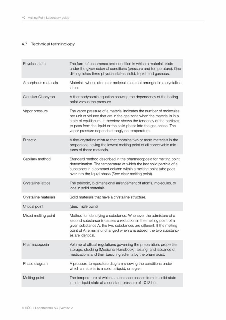
4.7 Technical terminology
Physical state The form of occurrence and condition in which a material exists under the given external conditions (pressure and temperature). One distinguishes three physical states: solid, liquid, and gaseous.
Amorphous materials Materials whose atoms or molecules are not arranged in a crystalline lattice.
Clausius-Clapeyron A thermodynamic equation showing the dependency of the boiling point versus the pressure.
Vapor pressure The vapor pressure of a material indicates the number of molecules per unit of volume that are in the gas zone when the material is in a state of equilibrium. It therefore shows the tendency of the particles to pass from the liquid or the solid phase into the gas phase. The vapor pressure depends strongly on temperature.
Eutectic A fine-crystalline mixture that contains two or more materials in the proportions having the lowest melting point of all conceivable mix-tures of those materials.
Capillary method Standard method described in the pharmacopoeia for melting point determination. The temperature at which the last solid particle of a substance in a compact column within a melting point tube goes over into the liquid phase (See: clear melting point).
Crystalline lattice The periodic, 3-dimensional arrangement of atoms, molecules, or ions in solid materials.
Crystalline materials Solid materials that have a crystalline structure.
Critical point (See: Triple point)
Mixed melting point Method for identifying a substance: Whenever the admixture of a second substance B causes a reduction in the melting point of a given substance A, the two substances are different. If the melting point of A remains unchanged when B is added, the two substanc-es are identical.
Pharmacopoeia Volume of official regulations governing the preparation, properties, storage, stocking (Medicinal Handbook), testing, and issuance of medications and their basic ingredients by the pharmacist.
Phase diagram A pressure-temperature diagram showing the conditions under which a material is a solid, a liquid, or a gas.
Melting point The temperature at which a substance passes from its solid state into its liquid state at a constant pressure of 1013 bar.
Melting Point Laboratory guide 41
© BÜCHI Labortechnik AG | Version A
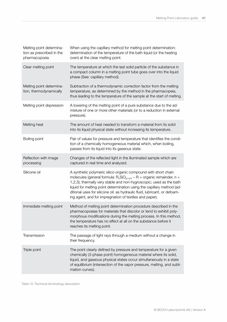
Melting point determina-tion as prescribed in the pharmacopoeia
When using the capillary method for melting point determination: determination of the temperature of the bath liquid (or the heating oven) at the clear melting point.
Clear melting point The temperature at which the last solid particle of the substance in a compact column in a melting point tube goes over into the liquid phase (See: capillary method).
Melting point determina-tion, thermodynamically
Subtraction of a thermodynamic correction factor from the melting temperature, as determined by the method in the pharmacopeia, thus leading to the temperature of the sample at the start of melting.
Melting point depression A lowering of the melting point of a pure substance due to the ad-mixture of one or more other materials (or to a reduction in external pressure).
Melting heat The amount of heat needed to transform a material from its solid into its liquid physical state without increasing its temperature.
Boiling point Pair of values for pressure and temperature that identifies the condi-tion of a chemically homogeneous material which, when boiling, passes from its liquid into its gaseous state.
Reflection with image processing
Changes of the reflected light in the illuminated sample which are captured in real time and analyzed.
Silicone oil A synthetic polymeric silico-organic compound with short chain molecules (general formula: RnSiO(4-n)/2 – R = organic remainder, n = 1,2,3); thermally very stable and non-hygroscopic; used as the bath liquid for melting point determination using the capillary method (ad-ditional uses for silicone oil: as hydraulic fluid, lubricant, or defoam-ing agent, and for impregnation of textiles and paper).
Immediate melting point Method of melting point determination procedure described in the pharmacopoeias for materials that discolor or tend to exhibit poly-morphous modifications during the melting process. In this method, the temperature has no effect at all on the substance before it reaches its melting point.
Transmission The passage of light rays through a medium without a change in their frequency.
Triple point The point clearly defined by pressure and temperature for a given chemically (3-phase point) homogeneous material where its solid, liquid, and gaseous physical states occur simultaneously in a state of equilibrium (intersection of the vapor pressure, melting, and subli-mation curves).
Table 12: Technical terminology description
42 Melting Point Laboratory guide
© BÜCHI Labortechnik AG | Version A
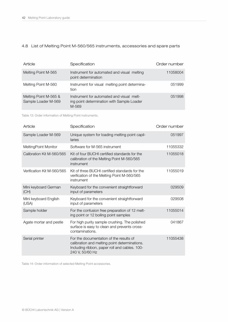
4.8 List of Melting Point M-560/565 instruments, accessories and spare parts
Article Specification Order number
Melting Point M-565 Instrument for automated and visual melting point determination
11058004
Melting Point M-560 Instrument for visual melting point determina-tion
051999
Melting Point M-565 & Sample Loader M-569
Instrument for automated and visual melt-ing point determination with Sample Loader M-569
051998
Table 13: Order information of Melting Point instruments.
Article Specification Order number
Sample Loader M-569 Unique system for loading melting point capil-laries
051997
MeltingPoint Monitor Software for M-565 instrument 11055332
Calibration Kit M-560/565 Kit of four BUCHI certified standards for the calibration of the Melting Point M-560/565 instrument
11055018
Verification Kit M-560/565 Kit of three BUCHI certified standards for the verification of the Melting Point M-560/565 instrument
11055019
Mini keyboard German (CH)
Keyboard for the convenient straightforward input of parameters
029509
Mini keyboard English (USA)
Keyboard for the convenient straightforward input of parameters
029508
Sample holder For the confusion free preparation of 12 melt-ing point or 12 boiling point samples
11055014
Agate mortar and pestle For high purity sample crushing. The polished surface is easy to clean and prevents cross-contaminations.
041867
Serial printer For the documentation of the results of calibration and melting point determinations. Including ribbon, paper roll and cables. 100-240 V, 50/60 Hz
11055438
Table 14: Order information of selected Melting Point accessories.
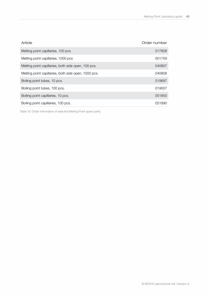
Melting Point Laboratory guide 43
© BÜCHI Labortechnik AG | Version A
Article Order number
Melting point capillaries, 100 pcs 017808
Melting point capillaries, 1000 pcs 001759
Melting point capillaries, both side open, 100 pcs. 040807
Melting point capillaries, both side open, 1000 pcs. 040808
Boiling point tubes, 10 pcs. 019697
Boiling point tubes, 100 pcs. 019007
Boiling point capillaries, 10 pcs. 051850
Boiling point capillaries, 100 pcs. 051890
Table 15: Order information of selected Melting Point spare parts.

11595103 Melting and biling guideen 1507 A /Technical data are subject to change without notice/Quality Systems ISO 9001.The English version is the original language version and serves as basis for all translations into other languages.
Quality in your hands
BUCHI Affiliates:
We are represented by more than 100 distribution partners worldwide. Find your local representative at: www.buchi.com
BUCHI Support Centers:
Europe
Switzerland/Austria
BÜCHI Labortechnik AGCH – 9230 Flawil T +41 71 394 63 63F +41 71 394 65 [email protected]
Benelux
BÜCHI Labortechnik GmbHBranch Offi ce BeneluxNL – 3342 GT T +31 78 684 94 29F +31 78 684 94 30 [email protected]
France
BUCHI SarlFR – 94656 Rungis CedexT +33 1 56 70 62 50F +33 1 46 86 00 [email protected]
Germany
BÜCHI Labortechnik GmbHDE – 45127 EssenT +800 414 0 414 0 (Toll Free)T +49 201 747 49 0F +49 201 747 49 20 [email protected]
Italy
BUCHI Italia s.r.l.IT – 20010 Cornaredo (MI)T +39 02 824 50 11F +39 02 575 12 [email protected]
Russia
BUCHI Russia/CISRussia 127287 MoscowT +7 495 36 36 495F +7 495 98 10 [email protected]
United Kingdom
BUCHI UK Ltd.GB – Oldham OL9 9QLT +44 161 633 1000F +44 161 633 [email protected]
Germany
BÜCHI NIR-OnlineDE – 69190 Walldorf T +49 6227 73 26 60F +49 6227 73 26 [email protected]
China
BUCHI ChinaCN – 200052 ShanghaiT +86 21 6280 3366F +86 21 5230 [email protected]
India
BUCHI India Private Ltd.IN – Mumbai 400 055 T +91 22 667 75400F +91 22 667 [email protected] www.buchi.in
Indonesia
PT. BUCHI IndonesiaID – Tangerang 15321T +62 21 537 62 16F +62 21 537 62 [email protected]
Japan
Nihon BUCHI K.K. JP – Tokyo 110-0008 T +81 3 3821 4777F +81 3 3821 [email protected]
Korea
BUCHI Korea Inc.KR – Seoul 153-782T +82 2 6718 7500F +82 2 6718 [email protected]
Malaysia
BUCHI Malaysia Sdn. Bhd. MY – 47301 Petaling Jaya, SelangorT +60 3 7832 0310F +60 3 7832 [email protected]
Singapore
BUCHI Singapore Pte. Ltd. SG – Singapore 609919T +65 6565 1175F +65 6566 [email protected]
Thailand
BUCHI (Thailand) Ltd. TH – Bangkok 10600T +66 2 862 08 51F +66 2 862 08 [email protected]
Asia
America
Brazil
BUCHI BrasilBR – Valinhos SP 13271-200T +55 19 3849 1201 F +55 19 3849 [email protected]
USA/Canada
BUCHI CorporationUS – New Castle, DE 19720T +1 877 692 8244 (Toll Free)T +1 302 652 3000F +1 302 652 [email protected]
South East Asia
BUCHI (Thailand) Ltd.TH-Bangkok 10600T +66 2 862 08 51F +66 2 862 08 [email protected]
Middle East
BÜCHI Labortechnik AGUAE – Dubai T +971 4 313 2860F +971 4 313 [email protected]
Latin America
BUCHI Latinoamérica Ltda.BR – Valinhos SP 13271-200T +55 19 3849 1201F +55 19 3849 [email protected]