Embed Size (px)
Citation preview
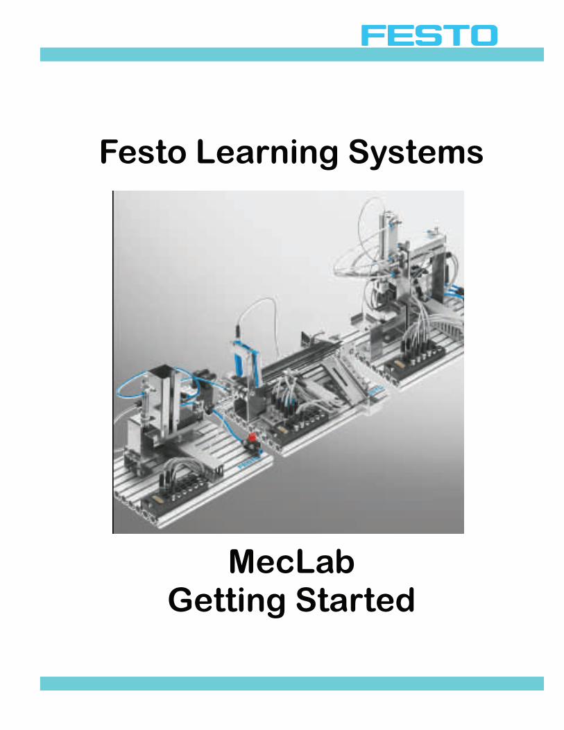
Festo Learning Systems
MecLab Getting Started
© 2008 Festo Corporation 2 U
By A. Huttner R. Pittschellis M. Klaus M. Hubsch M. Striegel T. Lust J. Schwarz Graphics: D. Schwarzenberger Layout: F. Ebel 05/2008 Editor: F. Ebel F. Zierau
Copyright 2008 This document and its contents are the property of Festo Corporation. No part of this document may be reproduced, utilized, transmitted or disclosed in any form or by any means without prior written consent of Festo Corporation
Festo Corporation 395 Moreland Rd. Hauppauge, NY, USA 11788
© 2008 Festo Corporation 3 U
Table of Contents Introduction 4
Course Objectives 5 Safety 6
Training Systems Operations 7 Overview 9 Commissioning 14 Sample Programs 15 Safety and Maintenance 16 Stack Magazine Station 18 Conveyor Station 40 Handling Station 56 Lesson Planning 77 Projects 86
© 2008 Festo Corporation 4 U
Introduction This workbook contains both information and exercises designed to introduce the student to basic automated systems components commonly used in industry. The information is intended for use in a mechatronics environment and is aimed at supporting continued education in industrial automation. The topics cover basic components used in in-dustrial automation. It also provides exercises for developing pneumatic and electrical sche-matics using FluidSim-P software. Overall the topics are intended to prepare the student to study more advanced systems.
© 2008 Festo Corporation 5 U
Course Objectives Upon completion of the exercises in this workbook, the student will be able to: • Identify machines and their function in a process. • Familiarization with industrial components. • Familiarization with industrial component symbols and designations. • Understand the term “sequence of operations”. • Become familiar with pneumatic and electrical schematics. • Understand control of linear actuators. • Understand principles of relays. • Understand limit switches.

© 2008 Festo Corporation 6 U
Safety * Due to the potential hazards in any automated system, good safety practices are important in the classroom, as well as on the production floor. Students should never be allowed to place their hands on or near the system while operating. Safety glasses should be worn around the equipment during operation.
*See also page 7, “Operation of the Festo Training System,” for additional safety considerations.
All information in this workbook is intended for educational use only. It has been carefully compiled and checked, and we believe the material to be accu-rately presented. However, Festo Corporation assumes no responsibility for published technical errors. Additionally, Festo Corporation assumes no re-sponsibility for the safe and/or satisfactory operation of any machine.
All information in this workbook is intended for educational use only. It has been carefully compiled and checked, and we believe the material to be accu-rately presented. However, Festo Corporation assumes no responsibility for published technical errors. Additionally, Festo Corporation assumes no re-sponsibility for the safe and/or satisfactory operation of any machine.
© 2008 Festo Corporation 7 U
Operation of the Festo Training System
Festo training systems have been designed for ease of use by both the student and the in-structor. Compressed air should be handled with respect. Care should be taken to ensure that com-pressed air is not directed at open cuts or against the skin, since serious physical damage and/or dangerous embolism may result. Compressed air should be applied to the service unit at the port next to the regulator/filter. Air service for the automated system is drawn from the right side of the service unit. The ser-vice unit is fitted with a normally closed 3/2 directional control valve with a red knob. The valve is opened to provide air to the manifold by moving the knob in line with the direction of airflow. All connections should be made with this switch turned off. All pneumatic components are fitted with quick-connect air line fittings. Tubing to be con-nected to these fittings should be cut squarely. Tubing is pushed into the fitting until a resis-tance is felt; this is a metal ring. The tubing is pressed further until it stops. The tubing is then checked by pulling gently back on the tubing. Leaks at the quick-connect fittings may sometimes be traced to failure to fully set the tubing in the fitting. Another common cause of air leaks may be a tubing end not cut at a shallow angle or tubing, which has become worn and ragged through use. These tubing faults may be corrected by cutting a short section from the end of the tubing to expose a fresh surface. The instructor should check the connections on the circuits to ensure that the tubing is se-cured properly before the circuits are pressurized. Compressed air escaping to atmosphere from a loose and uncontrolled tube will cause the tube to whip, therefore safety glasses should be worn whenever students or instructors are working or observing any of the auto-mated systems.

© 2008 Festo Corporation 8 U

© 2008 Festo Corporation 9 U
Getting Started with Festo MecLab
Overview Automation technology has become increasingly important in engineering. It helps to im-prove both working and living conditions by ensuring high productivity and quality while at the same time satisfying the ever-growing need for technological know-how. Automation technology combines knowledge from virtually all other technical sciences. This interdisciplinary field could not have developed without the fundamentals of electrical, me-chanical and process engineering as well as information technology to name just a few. We see and use automated technical systems every day. Escalators, automatic doors and ATMs. At the supermarket, our groceries are move by conveyors which seem to “know” ex-actly when to stop. In this sense, automation technology is everywhere. Everyone is regularly confronted by “something” that can be classified as an automated system. Thus technical education must emphasize this technology in order to keep up with the demand for skilled workers. Training should include: − Overview of automated systems. − Developing skills in the use of automated systems. − Developing skills in the commissioning and maintenance of automated technical systems. In addition, training must be designed so that students are given the opportunity to work with technology, investigate its effects and discover their own capabilities. Automation technology is one of the most challenging subjects because of its complexity. It can not be taught through lectures alone. Students must be given hands-on practice with automated technical systems in order to observe and understand how subsystems and com-ponents interact. They must be able to disassemble and assemble a system. MecLab®, developed by Festo Learning Systems, includes a stack magazine, a conveyor and a handling station. These simulate parts of an automated production line. It is designed to familiarize students with automated technical systems.

© 2008 Festo Corporation 10 U
Getting Started with Festo MecLab
Overview MecLab® is a modular multimedia teaching and learning system. It is supplemented with: − Computer software − Video − Technical drawings − Diagrams The combination of theory and practice is an essential aspect of MecLab® and its compo-nents. For every theory related to engineering sciences, there is a corresponding applica-tion. The connection between theory and practice will encourage students to put in to practice what they have learned. Additionally students can learn how to analyze practical applications to prove a theory. Individuals do not acquire a skill by simply listening to a description of the skills, rather they learn by doing. It is in the “doing” where problem solving skills are developed. Theory and practical applications of automation technology can be addressed with Me-cLab®, including: − Types of control systems. − Fundamentals of sensors. − The link between sensors and drives in automated systems. − Basic logic functions. − Basics of programming automated systems. MecLab® is intended for use in technically-oriented subjects. Basic knowledge of production engineering, mechanical engineering, electrical engineering and information technology is helpful, but not essential. Basic knowledge, such as physical fundamentals of drive and sen-sor technology, relays or logic operations can be learned with the help of the appropriate theory section as well as the exercises. The focus, however, should be less on teaching fun-damentals than on applying them.
© 2008 Festo Corporation 11 U
Getting Started with Festo MecLab
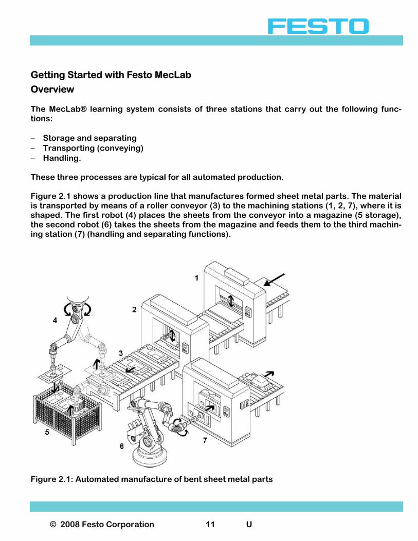
Overview The MecLab® learning system consists of three stations that carry out the following func-tions: − Storage and separating − Transporting (conveying) − Handling. These three processes are typical for all automated production. Figure 2.1 shows a production line that manufactures formed sheet metal parts. The material is transported by means of a roller conveyor (3) to the machining stations (1, 2, 7), where it is shaped. The first robot (4) places the sheets from the conveyor into a magazine (5 storage), the second robot (6) takes the sheets from the magazine and feeds them to the third machin-ing station (7) (handling and separating functions).
Figure 2.1: Automated manufacture of bent sheet metal parts
© 2008 Festo Corporation 12 U
Getting Started with Festo MecLab
Overview The MecLab® stations perform the following functions: Stack magazine station: Stores and separates work pieces. An additional function, either “stamping” or “insertion”, can be performed by the stamping unit. Conveyor station: Transports work pieces. An additional function, “sorting” or “rejection”, can be performed by the ejecting solenoid. Handling station: Transfers work pieces between two points which can not be covered by conveyor. The function of each station can be modified by adding or removing components. For exam-ple if the ejecting solenoid is removed from the conveyor station, it can still convey but no longer sort. If the solenoid is moved from one side of the conveyor to the other, the deflector becomes a stopper. Stations are controlled using FluidSIM® simulation and control program in combination with a modified EasyPort. This allows FluidSIM® to read sensor signals from the stations and to ac-tuate the drives of each station. It is also used to connect the stations with the USB interface of the PC. The software contains sample programs designed to help the student “get started” with pro-gramming. Since the Meclab system is made of industrial components, it is also possible to perform “manual override” operations. Students are encouraged to use the provided tools to disassemble and reassemble the sta-tions. The stations can be used independently or joined together to form a production line.

© 2008 Festo Corporation 13 U
Getting Started with Festo MecLab
Overview The Meclab system consists of the following: − 1 compressor for supplying the stations with compressed air − 6 licenses of FluidSIM for MECLAB® simulation and control program − 3 modified EasyPorts for connecting the stations to a PC − 3 power supply units for supplying power to the EasyPort − 3 sets of workpieces − 3 sets of tools and small parts − All instruction material (e.g. this book) on CD-ROM The following information can be found on the supplied CD-ROM: − Introduction: Teaching with Meclab (this document) − Instructions for commissioning the three stations − Theory section: Explains key technologies, components and other relevant information − Exercise sheets: Designed to assist the student in becoming familiar with automated sys-
tems , relevant technologies and project planning − PowerPoint presentation
© 2008 Festo Corporation 14 U
Getting Started with Festo MecLab
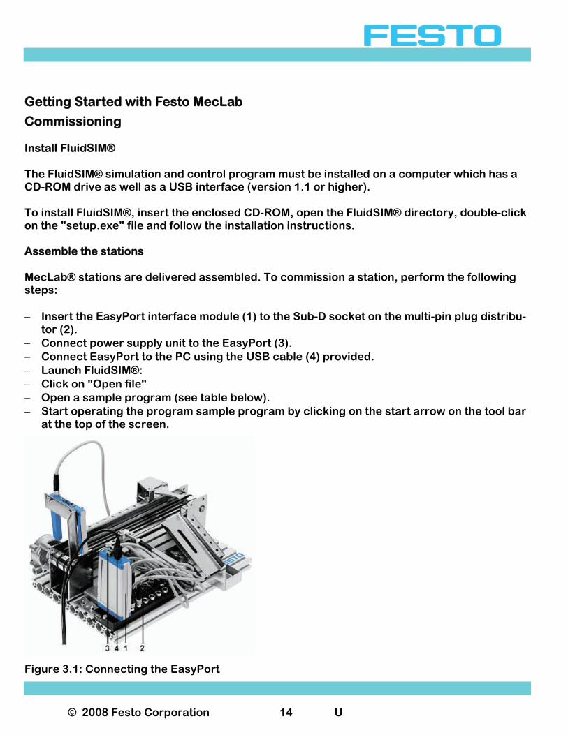
Commissioning Install FluidSIM® The FluidSIM® simulation and control program must be installed on a computer which has a CD-ROM drive as well as a USB interface (version 1.1 or higher). To install FluidSIM®, insert the enclosed CD-ROM, open the FluidSIM® directory, double-click on the "setup.exe" file and follow the installation instructions. Assemble the stations MecLab® stations are delivered assembled. To commission a station, perform the following steps: − Insert the EasyPort interface module (1) to the Sub-D socket on the multi-pin plug distribu-
tor (2). − Connect power supply unit to the EasyPort (3). − Connect EasyPort to the PC using the USB cable (4) provided. − Launch FluidSIM®: − Click on "Open file" − Open a sample program (see table below). − Start operating the program sample program by clicking on the start arrow on the tool bar
at the top of the screen.
Figure 3.1: Connecting the EasyPort
© 2008 Festo Corporation 15 U
Program Station Function
1-4.ct
Stack magazine
Manually activate single-acting cylinders
1-5.ct
Stack magazine
Manually activate double-acting cylinders
1-7.ct
Stack magazine
Separate and press lids onto containers (automatic)
2-5a.ct
Conveyor
Activate conveyor by means of a through-beam sensor
2-7.ct Conveyor
Activate conveyor by means of a through-beam sensor. Sort metal work pieces and de-activate the conveyor after 5 seconds.
2-8.ct
Conveyor Activate conveyor by means of a through-beam sensor. Sort metal work pieces and de-activate the conveyor after 5 seconds . Manually reverse conveyor direction.
DC MOTOR RELAY. ct
Conveyor Manually activate/deactivate conveyor. Reverse conveyor di-rection.
3-4.ct Handling Manually advance “z” axis 3-6.ct Handling Automatically advance “z” axis in continuous operation. 3-7.ct
Handling Automatically reposition work piece from rear to the front storage plate.
Getting Started with Festo MecLab
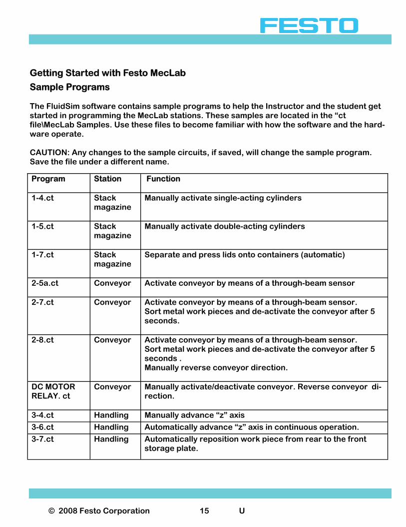
Sample Programs The FluidSim software contains sample programs to help the Instructor and the student get started in programming the MecLab stations. These samples are located in the “ct file\MecLab Samples. Use these files to become familiar with how the software and the hard-ware operate. CAUTION: Any changes to the sample circuits, if saved, will change the sample program. Save the file under a different name.
© 2008 Festo Corporation 16 U
Getting Started with Festo MecLab
Safety and Maintenance MecLab® has been designed in compliance with all relevant safety guidelines. As with all technical systems, there is additional safety information that must be observed.
General Students must be supervised at all times when working on the stations. Read Data sheets and note individual station safety information. Electrical components Electrical power must be disconnected before making or breaking electrical connections. Use only extra low voltages (max. 24 V DC).
Pneumatic components − Do not exceed 60 psi (4 bar). − Do not turn on compressed air until all tubing connections have been established and se-
cured. − Do not uncouple tubing under pressure. − Be alert for “pinch points” when switching on compressed air as cylinders can automati-
cally extend or retract. − Loose tubing can “whip” rapidly causing serious eye injury. Ensure that “main air” is
turned off before disconnecting or connecting tubing. − Always wear safety goggles when working on or near the system. − Select tubing length that will provide the shortest connection between two ports. Pneumatic circuit assembly: − Connect devices using plastic tubing with an outside diameter of either 4 or 6 mm
(whichever is appropriate) − Push the tubing as far as possible into the push-in connector.

© 2008 Festo Corporation 17 U
Getting Started with Festo MecLab
Safety and Maintenance Pneumatic circuit disassembly:
− Switch off the compressed air supply before disassembling the circuit. − Press down on the blue release ring to pull out the tubing.
Compressor Air pressure can be regulated at the compressor: − Pull out the rotary knob on the pressure regulator and turn until pressure gauge shows
the required pressure. − Push rotary knob back in (this locks the regulator). − Do not touch the compressor once started as it can become extremely hot during opera-
tion. − After switching off the compressor, release the pressure from the compressor tank. − Do not leave the compressor running uninterrupted for more than one hour. Mechanical components − Install all components securely on the plate. − Do not place your hand in the station while it is running. Maintenance information MecLab® is essentially maintenance-free. Wipe occasionally with a dry, lint free rag. Water must be drained from the compressor tank or water separator (at the regulator) at regular intervals. Inspect compressor tank regularly for damage.
© 2008 Festo Corporation 18 U
Getting Started with Festo MecLab
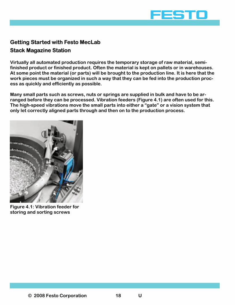
Stack Magazine Station Virtually all automated production requires the temporary storage of raw material, semi-finished product or finished product. Often the material is kept on pallets or in warehouses. At some point the material (or parts) will be brought to the production line. It is here that the work pieces must be organized in such a way that they can be fed into the production proc-ess as quickly and efficiently as possible. Many small parts such as screws, nuts or springs are supplied in bulk and have to be ar-ranged before they can be processed. Vibration feeders (Figure 4.1) are often used for this. The high-speed vibrations move the small parts into either a “gate” or a vision system that only let correctly aligned parts through and then on to the production process.
Figure 4.1: Vibration feeder for storing and sorting screws
© 2008 Festo Corporation 19 U
Getting Started with Festo MecLab
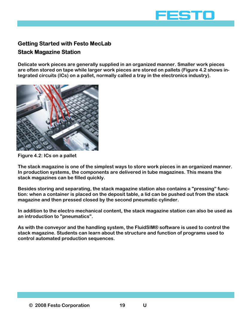
Stack Magazine Station Delicate work pieces are generally supplied in an organized manner. Smaller work pieces are often stored on tape while larger work pieces are stored on pallets (Figure 4.2 shows in-tegrated circuits (ICs) on a pallet, normally called a tray in the electronics industry).
Figure 4.2: ICs on a pallet The stack magazine is one of the simplest ways to store work pieces in an organized manner. In production systems, the components are delivered in tube magazines. This means the stack magazines can be filled quickly. Besides storing and separating, the stack magazine station also contains a "pressing” func-tion: when a container is placed on the deposit table, a lid can be pushed out from the stack magazine and then pressed closed by the second pneumatic cylinder. In addition to the electro mechanical content, the stack magazine station can also be used as an introduction to "pneumatics". As with the conveyor and the handling system, the FluidSIM® software is used to control the stack magazine. Students can learn about the structure and function of programs used to control automated production sequences.
© 2008 Festo Corporation 20 U
Getting Started with Festo MecLab
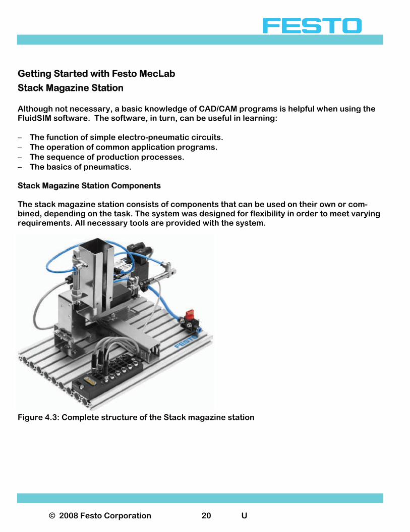
Stack Magazine Station Although not necessary, a basic knowledge of CAD/CAM programs is helpful when using the FluidSIM software. The software, in turn, can be useful in learning: − The function of simple electro-pneumatic circuits. − The operation of common application programs. − The sequence of production processes. − The basics of pneumatics. Stack Magazine Station Components The stack magazine station consists of components that can be used on their own or com-bined, depending on the task. The system was designed for flexibility in order to meet varying requirements. All necessary tools are provided with the system.
Figure 4.3: Complete structure of the Stack magazine station
© 2008 Festo Corporation 21 U
Getting Started with Festo MecLab
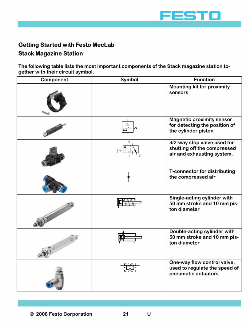
Stack Magazine Station The following table lists the most important components of the Stack magazine station to-gether with their circuit symbol.
Component Symbol Function
Mounting kit for proximity sensors
Magnetic proximity sensor for detecting the position of the cylinder piston
3/2-way stop valve used for shutting off the compressed air and exhausting system.
T-connector for distributing the compressed air
Single-acting cylinder with 50 mm stroke and 10 mm pis-ton diameter
Double-acting cylinder with 50 mm stroke and 10 mm pis-ton diameter
One-way flow control valve, used to regulate the speed of pneumatic actuators
© 2008 Festo Corporation 22 U
Getting Started with Festo MecLab
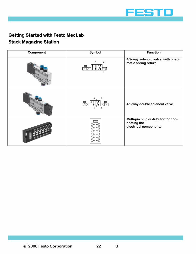
Stack Magazine Station
Component Symbol Function
4/2-way solenoid valve, with pneu-matic spring return
4/2-way double solenoid valve
Multi-pin plug distributor for con-necting the electrical components
© 2008 Festo Corporation 23 U
Getting Started with Festo MecLab
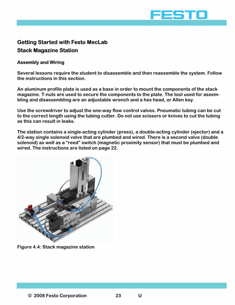
Stack Magazine Station Assembly and Wiring Several lessons require the student to disassemble and then reassemble the system. Follow the instructions in this section. An aluminum profile plate is used as a base in order to mount the components of the stack magazine. T-nuts are used to secure the components to the plate. The tool used for assem-bling and disassembling are an adjustable wrench and a hex head, or Allen key. Use the screwdriver to adjust the one-way flow control valves. Pneumatic tubing can be cut to the correct length using the tubing cutter. Do not use scissors or knives to cut the tubing as this can result in leaks. The station contains a single-acting cylinder (press), a double-acting cylinder (ejector) and a 4/2-way single solenoid valve that are plumbed and wired. There is a second valve (double solenoid) as well as a “reed” switch (magnetic proximity sensor) that must be plumbed and wired. The instructions are listed on page 22.
Figure 4.4: Stack magazine station
© 2008 Festo Corporation 24 U
Getting Started with Festo MecLab
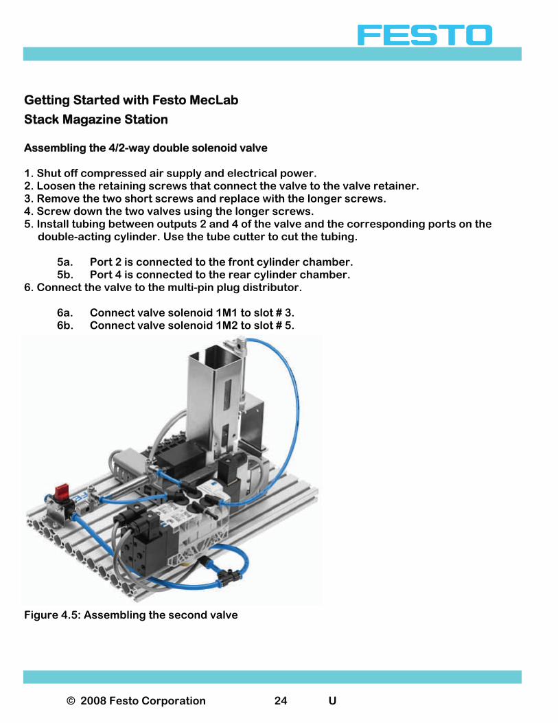
Stack Magazine Station Assembling the 4/2-way double solenoid valve 1. Shut off compressed air supply and electrical power. 2. Loosen the retaining screws that connect the valve to the valve retainer. 3. Remove the two short screws and replace with the longer screws. 4. Screw down the two valves using the longer screws. 5. Install tubing between outputs 2 and 4 of the valve and the corresponding ports on the double-acting cylinder. Use the tube cutter to cut the tubing. 5a. Port 2 is connected to the front cylinder chamber. 5b. Port 4 is connected to the rear cylinder chamber. 6. Connect the valve to the multi-pin plug distributor. 6a. Connect valve solenoid 1M1 to slot # 3. 6b. Connect valve solenoid 1M2 to slot # 5.
Figure 4.5: Assembling the second valve
© 2008 Festo Corporation 25 U
Getting Started with Festo MecLab
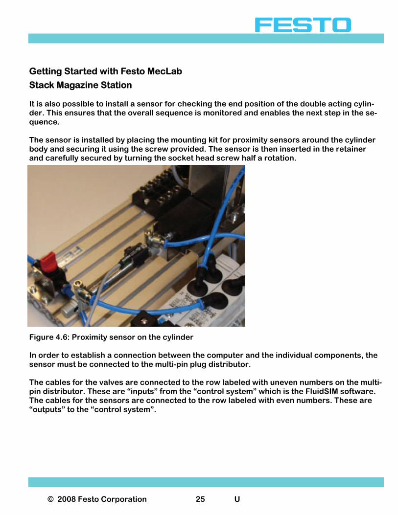
Stack Magazine Station It is also possible to install a sensor for checking the end position of the double acting cylin-der. This ensures that the overall sequence is monitored and enables the next step in the se-quence. The sensor is installed by placing the mounting kit for proximity sensors around the cylinder body and securing it using the screw provided. The sensor is then inserted in the retainer and carefully secured by turning the socket head screw half a rotation.
Figure 4.6: Proximity sensor on the cylinder In order to establish a connection between the computer and the individual components, the sensor must be connected to the multi-pin plug distributor. The cables for the valves are connected to the row labeled with uneven numbers on the multi-pin distributor. These are “inputs” from the “control system” which is the FluidSIM software. The cables for the sensors are connected to the row labeled with even numbers. These are “outputs” to the “control system”.
© 2008 Festo Corporation 26 U
Getting Started with Festo MecLab
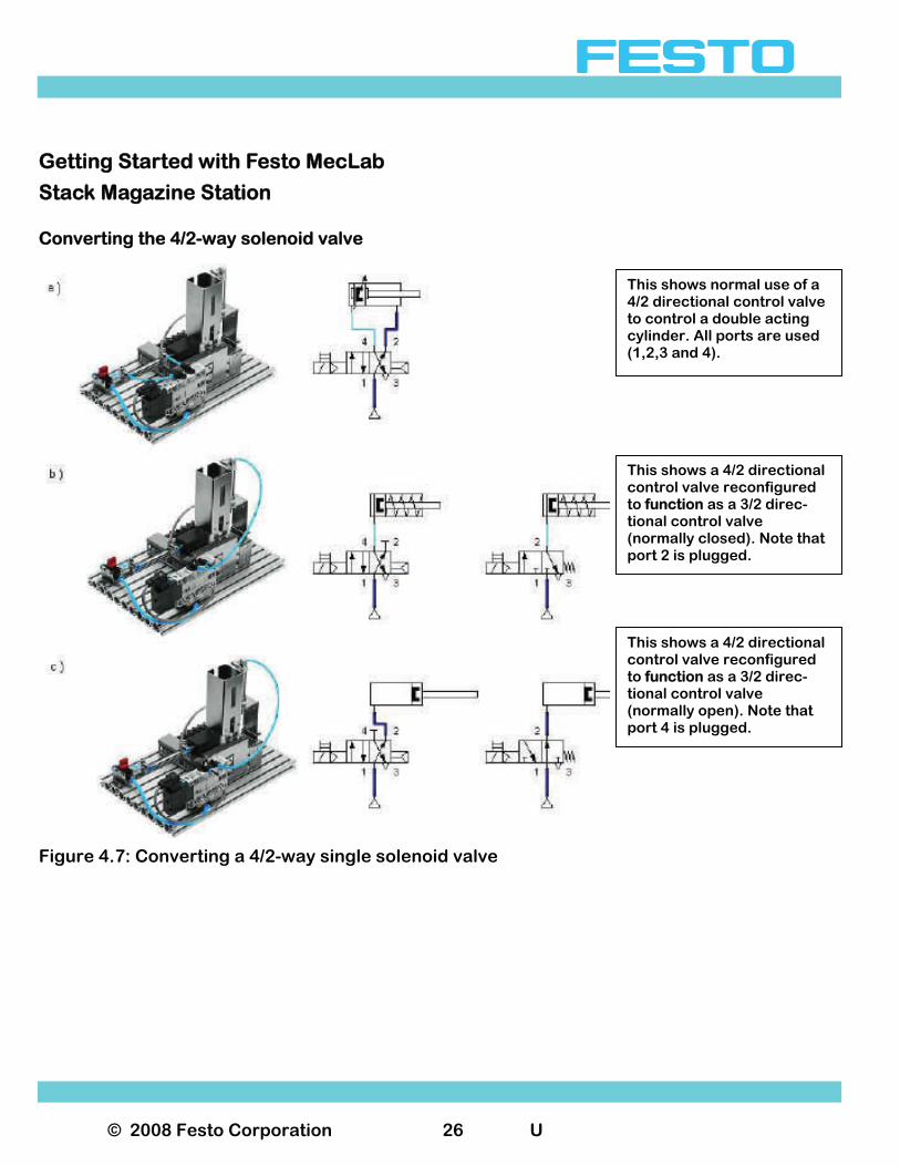
Stack Magazine Station Converting the 4/2-way solenoid valve
Figure 4.7: Converting a 4/2-way single solenoid valve
This shows normal use of a 4/2 directional control valve to control a double acting cylinder. All ports are used (1,2,3 and 4).
This shows a 4/2 directional control valve reconfigured to function as a 3/2 direc-tional control valve (normally closed). Note that port 2 is plugged.
This shows a 4/2 directional control valve reconfigured to function as a 3/2 direc-tional control valve (normally open). Note that port 4 is plugged.
© 2008 Festo Corporation 27 U
Getting Started with Festo MecLab
Stack Magazine Station a) 4/2-way solenoid valve (normal use in combination with a double-acting cylinder) b) 3/2-way solenoid valve normally closed (in combination with a single-acting cylinder; port 2 is “plugged”) c) 3/2-way solenoid valve, normally open (in combination with a single-acting cylinder; port 4 is “plugged”, the cylinder is advanced in the switching position shown) The station contains two valves they are both 4/2-way directional control valves. This means that they each have 4 ports and 2 positions. The difference is in how the valves are actuated. One valve is actuated by means of single solenoid the other is actuated by means of two so-lenoids. The 4/2-way valve can be converted to a 3/2-way valve by sealing one of the two outputs. The decision to seal one of the two output ports should be made after deciding which type of valve is desired, normally closed or normally open. The 4/2-way single solenoid valve is supplied with output 4 sealed, producing a 3/2-way nor-mally closed valve. In this configuration the valve can be used to activate the single-acting cylinder (stamping cylinder). Opening output 4 produces a 4/2-way valve for actuating the double-acting cylinder. Sealing output 2 produces a 3/2-way normally open valve. If this valve is used, the single act-ing cylinder will extend when the valve is not actuated and retract when the valve is actuated.
© 2008 Festo Corporation 28 U
Getting Started with Festo MecLab
Stack Magazine Station Sample exercise using the stack magazine The purpose of this section is to explain the interaction of the FluidSIM® software and the hardware components of the stack magazine station using a sample exercise. Task 1. Build a stack magazine that pushes out one work piece when a button is momentarily
pressed. 2. When a second button is pressed, the stack magazine returns to its normal position. Analysis of the task 1. The signal to advance must be “remembered” since the pushbutton is to be briefly or mo-
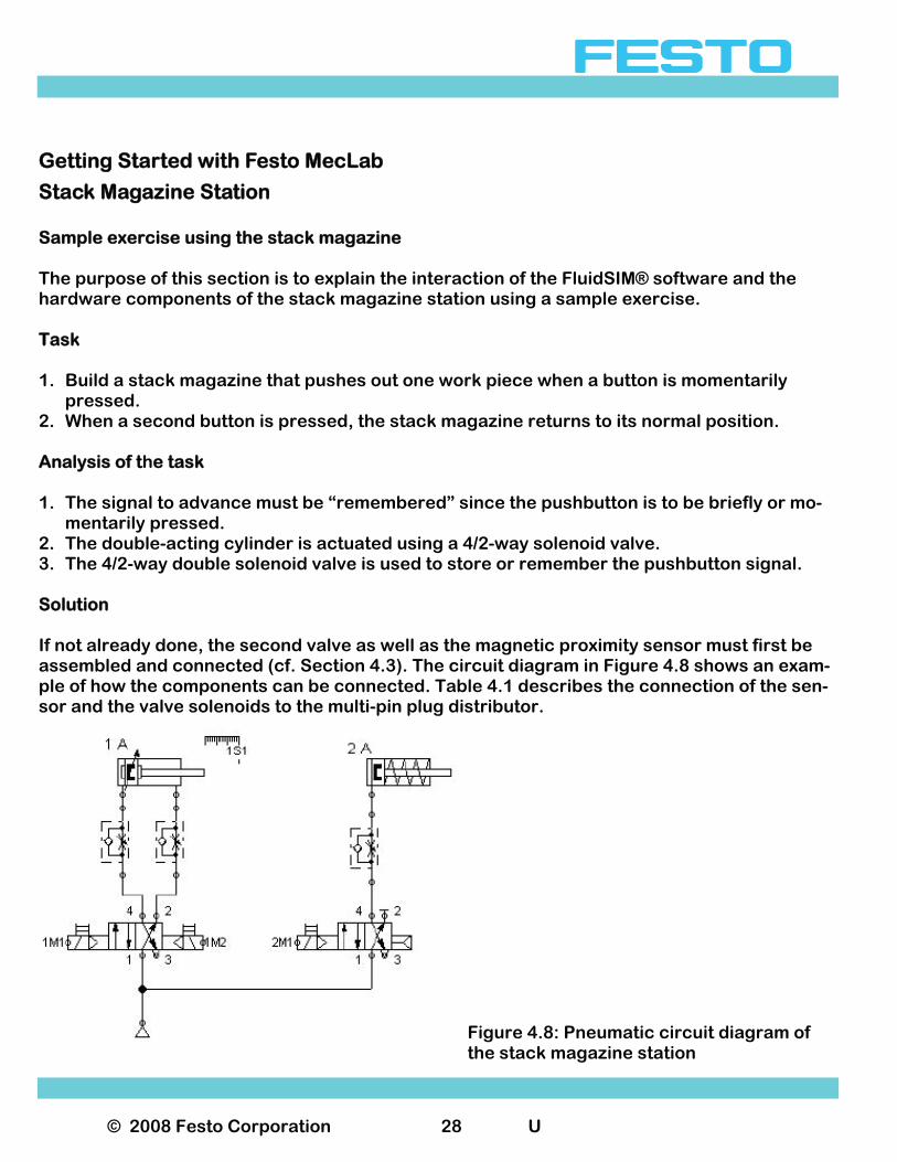
mentarily pressed. 2. The double-acting cylinder is actuated using a 4/2-way solenoid valve. 3. The 4/2-way double solenoid valve is used to store or remember the pushbutton signal. Solution If not already done, the second valve as well as the magnetic proximity sensor must first be assembled and connected (cf. Section 4.3). The circuit diagram in Figure 4.8 shows an exam-ple of how the components can be connected. Table 4.1 describes the connection of the sen-sor and the valve solenoids to the multi-pin plug distributor.
Figure 4.8: Pneumatic circuit diagram of the stack magazine station

© 2008 Festo Corporation 29 U
Getting Started with Festo MecLab
Stack Magazine Station
Table 4.1: Pin allocation for the stack magazine station The following are the steps necessary to launch and configure the control software: Step 1: Launch the FluidSIM® program Open the FluidSIM® program by double-clicking on the program icon.
Call up a new workspace. Click on the blank white page on the left in the second menu bar. A new blank workspace appears. This will be the “controller”.
Save the new controller To do this, select "File > Save As ..." in the menu bar and save the file to the desired location.
Slot Assignment Label
0 Sensor 1S1
1 Valve solenoid 2M1
3 Valve solenoid 1M1
5 Valve solenoid 1M2
© 2008 Festo Corporation 30 U
Getting Started with Festo MecLab
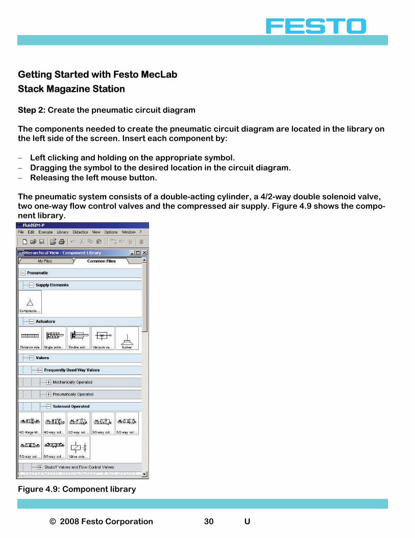
Stack Magazine Station Step 2: Create the pneumatic circuit diagram The components needed to create the pneumatic circuit diagram are located in the library on the left side of the screen. Insert each component by: − Left clicking and holding on the appropriate symbol. − Dragging the symbol to the desired location in the circuit diagram. − Releasing the left mouse button. The pneumatic system consists of a double-acting cylinder, a 4/2-way double solenoid valve, two one-way flow control valves and the compressed air supply. Figure 4.9 shows the compo-nent library.
Figure 4.9: Component library
© 2008 Festo Corporation 31 U
Getting Started with Festo MecLab
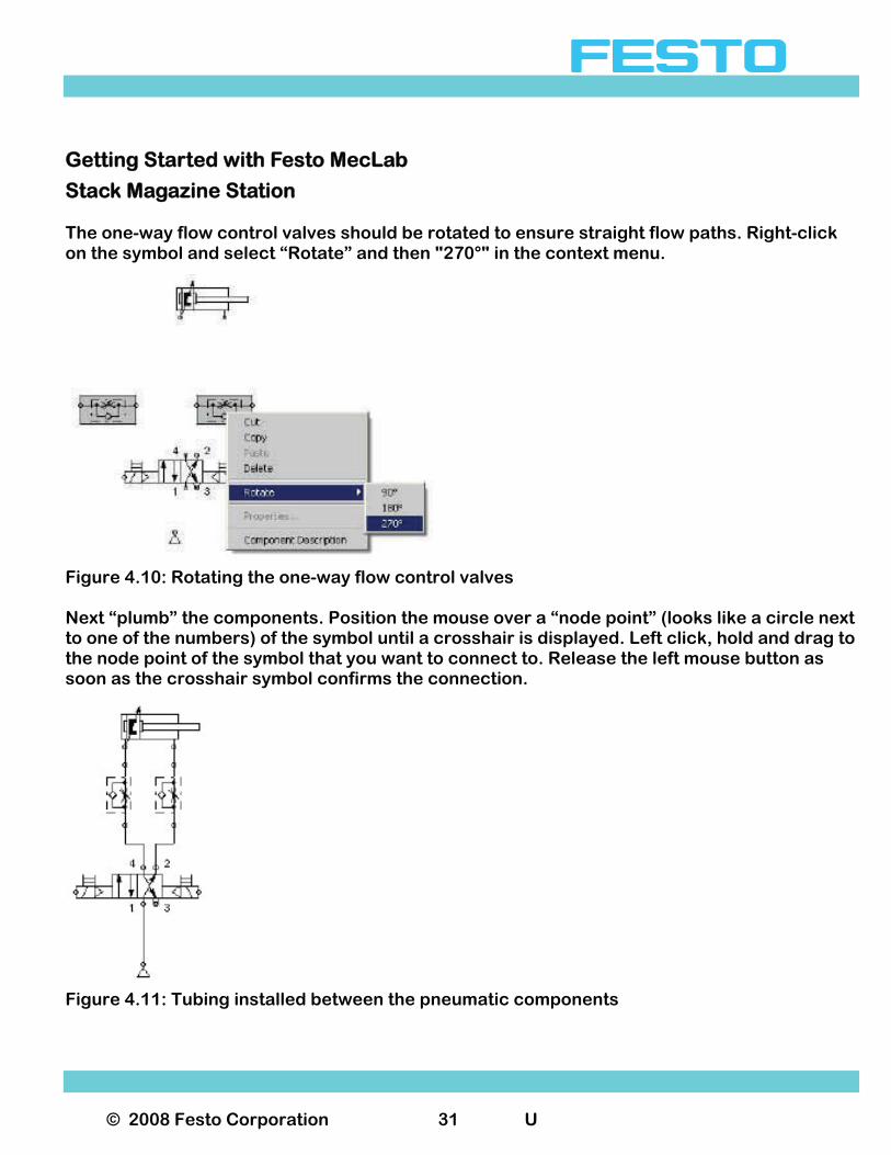
Stack Magazine Station The one-way flow control valves should be rotated to ensure straight flow paths. Right-click on the symbol and select “Rotate” and then "270°" in the context menu.
Figure 4.10: Rotating the one-way flow control valves Next “plumb” the components. Position the mouse over a “node point” (looks like a circle next to one of the numbers) of the symbol until a crosshair is displayed. Left click, hold and drag to the node point of the symbol that you want to connect to. Release the left mouse button as soon as the crosshair symbol confirms the connection.
Figure 4.11: Tubing installed between the pneumatic components
© 2008 Festo Corporation 32 U
Getting Started with Festo MecLab
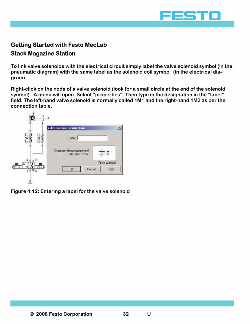
Stack Magazine Station To link valve solenoids with the electrical circuit simply label the valve solenoid symbol (in the pneumatic diagram) with the same label as the solenoid coil symbol (in the electrical dia-gram). Right-click on the node of a valve solenoid (look for a small circle at the end of the solenoid symbol). A menu will open. Select “properties". Then type in the designation in the “label” field. The left-hand valve solenoid is normally called 1M1 and the right-hand 1M2 as per the connection table.
Figure 4.12: Entering a label for the valve solenoid
© 2008 Festo Corporation 33 U
Getting Started with Festo MecLab
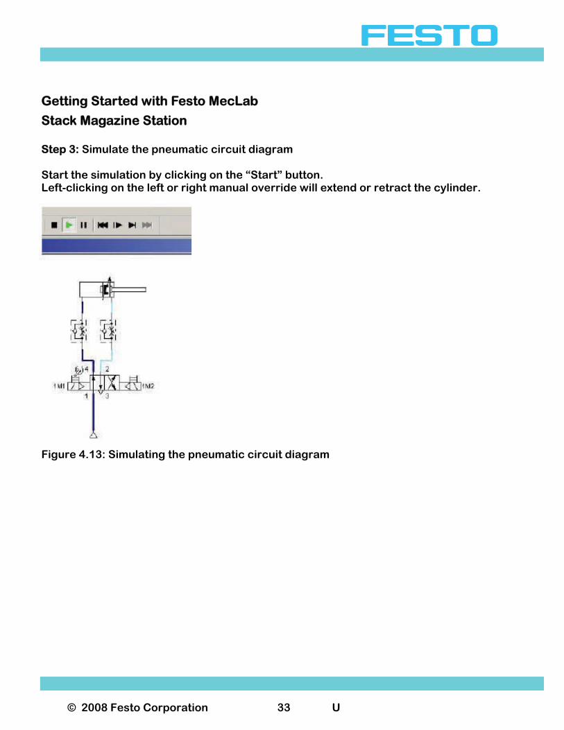
Stack Magazine Station Step 3: Simulate the pneumatic circuit diagram Start the simulation by clicking on the “Start” button. Left-clicking on the left or right manual override will extend or retract the cylinder.
Figure 4.13: Simulating the pneumatic circuit diagram
© 2008 Festo Corporation 34 U
Getting Started with Festo MecLab
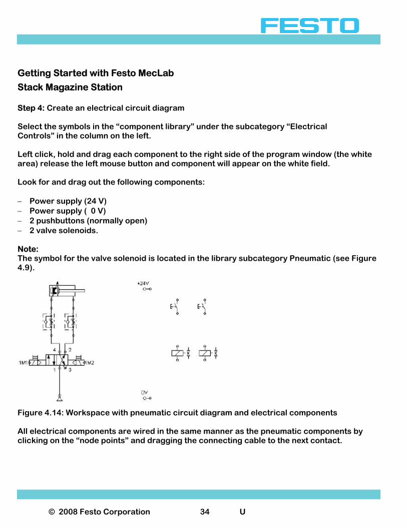
Stack Magazine Station Step 4: Create an electrical circuit diagram Select the symbols in the “component library” under the subcategory “Electrical Controls” in the column on the left. Left click, hold and drag each component to the right side of the program window (the white area) release the left mouse button and component will appear on the white field. Look for and drag out the following components: − Power supply (24 V) − Power supply ( 0 V) − 2 pushbuttons (normally open) − 2 valve solenoids. Note: The symbol for the valve solenoid is located in the library subcategory Pneumatic (see Figure 4.9).
Figure 4.14: Workspace with pneumatic circuit diagram and electrical components All electrical components are wired in the same manner as the pneumatic components by clicking on the “node points” and dragging the connecting cable to the next contact.
© 2008 Festo Corporation 35 U
Getting Started with Festo MecLab
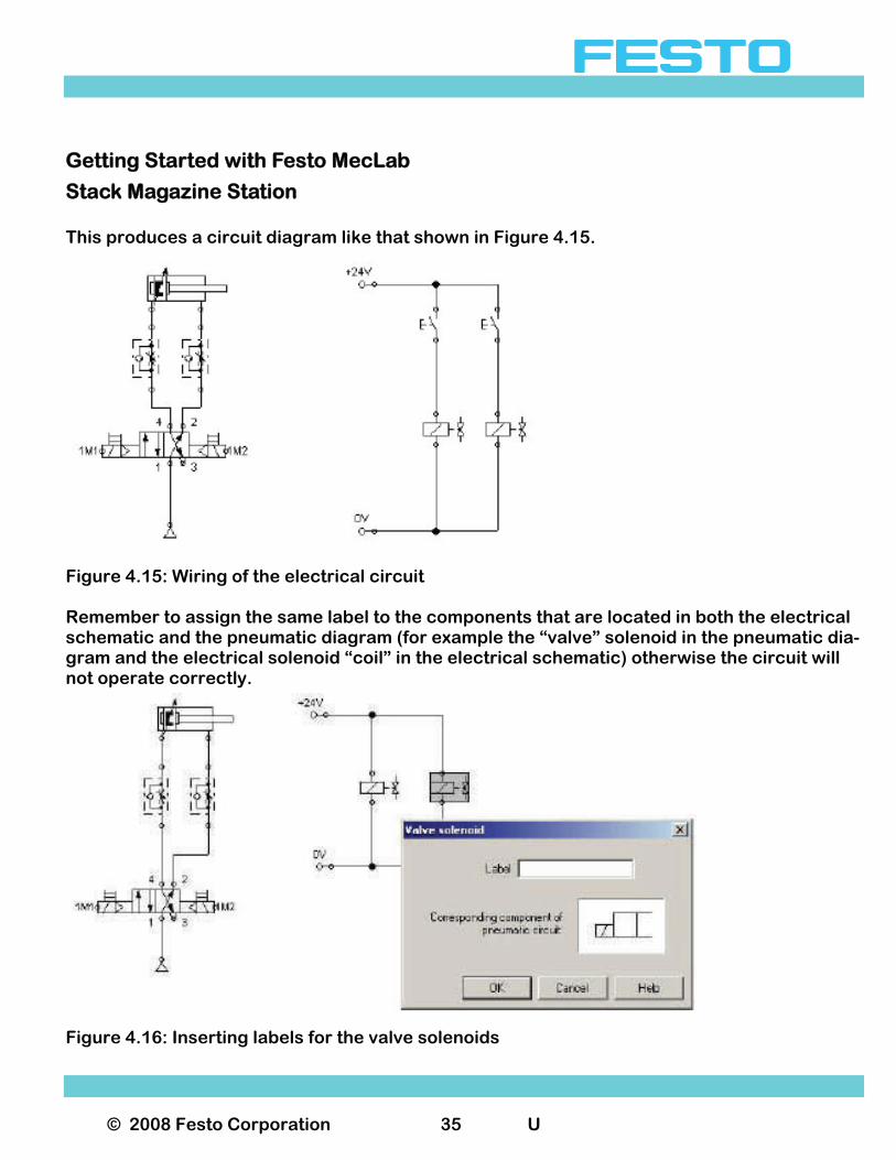
Stack Magazine Station This produces a circuit diagram like that shown in Figure 4.15.
Figure 4.15: Wiring of the electrical circuit Remember to assign the same label to the components that are located in both the electrical schematic and the pneumatic diagram (for example the “valve” solenoid in the pneumatic dia-gram and the electrical solenoid “coil” in the electrical schematic) otherwise the circuit will not operate correctly.
Figure 4.16: Inserting labels for the valve solenoids

© 2008 Festo Corporation 36 U
Getting Started with Festo MecLab
Stack Magazine Station Step 5: Simulate the entire circuit Pressing the start button executes the simulation in FluidSIM®. This is an easy and safe way of testing the operation of the electrical and pneumatic circuits. To execute the individual program steps, the pushbuttons must be actuated in simulation mode by clicking on them with the mouse. Actuating the left pushbutton closes the circuit, the solenoid valve reverses, the valve opens the path for the compressed air and the pneu-matic cylinder extends. Actuating the right pushbutton retracts the cylinder piston to its initial position. Note the following in FluidSIM®: Pneumatic circuit: Light blue lines represent lines that are not supplied with compressed air. Dark blue lines represent lines that are pressurized. Electrical circuit: Red lines represent the path in the circuit that is conducting current.
Figure 4.17: Simulating the electro pneumatic circuit
© 2008 Festo Corporation 37 U
Getting Started with Festo MecLab
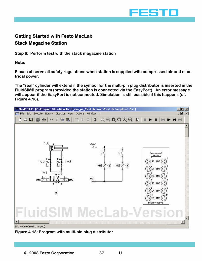
Stack Magazine Station Step 6: Perform test with the stack magazine station Note: Please observe all safety regulations when station is supplied with compressed air and elec-trical power. The “real” cylinder will extend if the symbol for the multi-pin plug distributor is inserted in the FluidSIM® program (provided the station is connected via the EasyPort). An error message will appear if the EasyPort is not connected. Simulation is still possible if this happens (cf. Figure 4.18).
Figure 4.18: Program with multi-pin plug distributor
© 2008 Festo Corporation 38 U
Getting Started with Festo MecLab
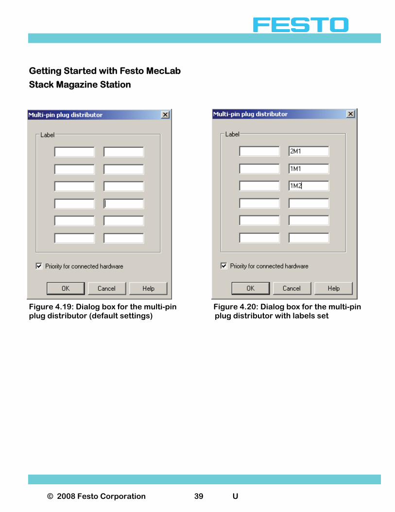
Stack Magazine Station Labels in the symbolic multi-pin plug distributor must be assigned. Open the symbol by dou-ble-clicking on it (Figure 4.19). Labels are then assigned as per Table 4.1. The labels must match those used in the pneu-matic and electrical circuit diagrams. The multi-pin plug symbol will then establish the con-nection to the stack magazine station. It makes no difference what the labels are called (1M1 is a typical designation. It could also be called "left valve solenoid" or “Joes solenoid” if you wish). The only important thing is that the same labels are used for the same element in the pneumatic and electrical circuit dia-grams and that this element is plugged into the correct slot on the multi-pin plug distributor. Note: The "Priority when hardware connected" box must be ticked. This ensures that the signals for the actual sensors are used and not those simulated in the program. If the simulation is started and pushbutton S1 is actuated, the cylinder in the station will ex-tend. The status of the input and output channels is indicated in color in the multi-pin plug symbol. On the multi-pin plug distributor in the stack magazine station, the status of the input and out-put channels are indicated by LEDs. The program can now be extended step-by-step to incor-porate the other actuators and sensors into the station.
© 2008 Festo Corporation 39 U
Getting Started with Festo MecLab
Stack Magazine Station
Figure 4.19: Dialog box for the multi-pin Figure 4.20: Dialog box for the multi-pin plug distributor (default settings) plug distributor with labels set
© 2008 Festo Corporation 40 U
Getting Started with Festo MecLab
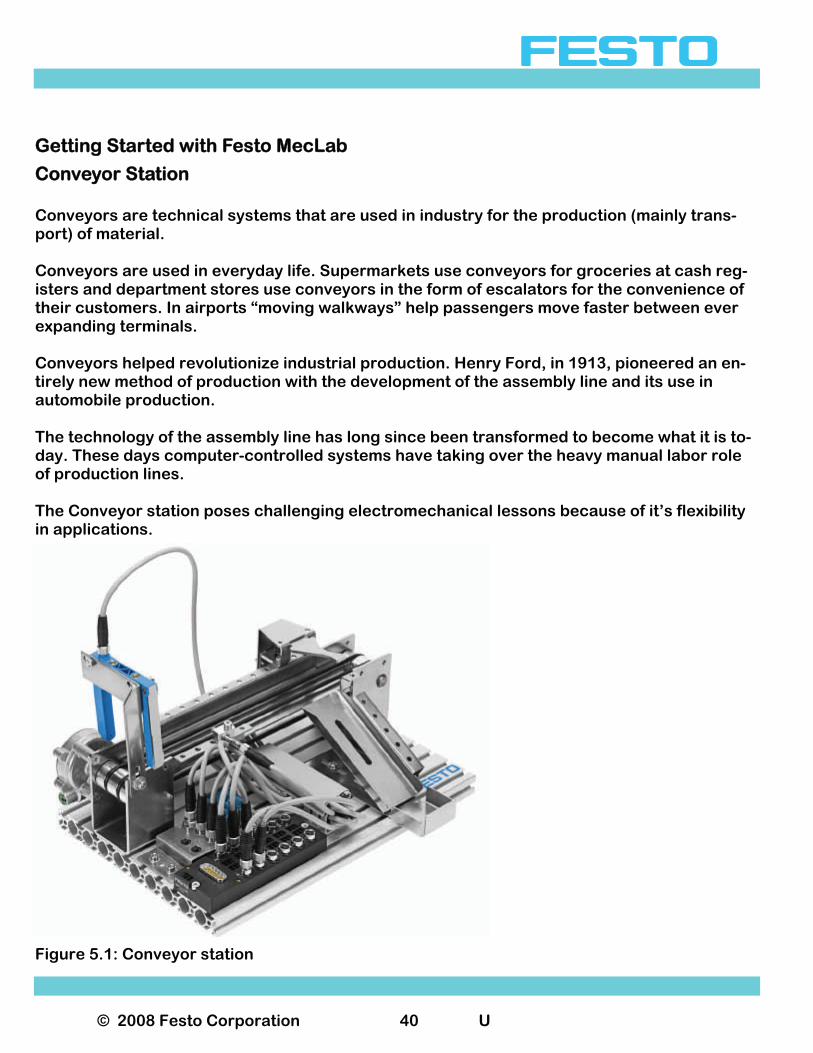
Conveyor Station Conveyors are technical systems that are used in industry for the production (mainly trans-port) of material. Conveyors are used in everyday life. Supermarkets use conveyors for groceries at cash reg-isters and department stores use conveyors in the form of escalators for the convenience of their customers. In airports “moving walkways” help passengers move faster between ever expanding terminals. Conveyors helped revolutionize industrial production. Henry Ford, in 1913, pioneered an en-tirely new method of production with the development of the assembly line and its use in automobile production. The technology of the assembly line has long since been transformed to become what it is to-day. These days computer-controlled systems have taking over the heavy manual labor role of production lines. The Conveyor station poses challenging electromechanical lessons because of it’s flexibility in applications.
Figure 5.1: Conveyor station
© 2008 Festo Corporation 41 U
Getting Started with Festo MecLab
Conveyor Station The conveyor station can be used as one of three processes in a production assembly line or as a stand-alone single unit. The following assumes that the conveyor is to be used as a stand-alone unit. The unit consists of modules that can be disassembled into individual components. This pro-vides flexibility when conducting the lessons: − The conveyor can be used as a complete technical system for one set of lessons. − The conveyor module or each modules individual components can be used for another set
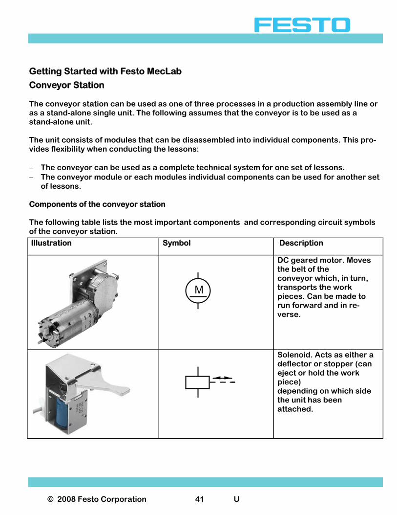
of lessons. Components of the conveyor station The following table lists the most important components and corresponding circuit symbols of the conveyor station.
Illustration Symbol Description
M
DC geared motor. Moves the belt of the conveyor which, in turn, transports the work pieces. Can be made to run forward and in re-verse.
Solenoid. Acts as either a deflector or stopper (can eject or hold the work piece) depending on which side the unit has been attached.
© 2008 Festo Corporation 42 U
Getting Started with Festo MecLab
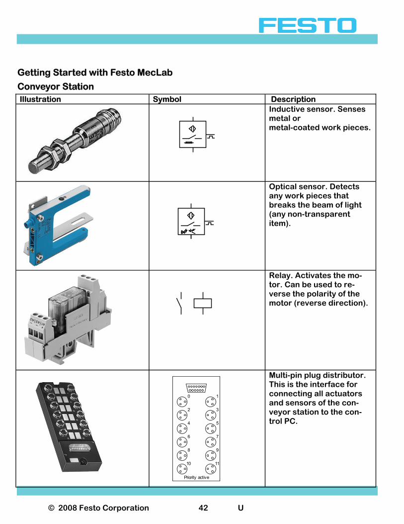
Conveyor Station Illustration Symbol Description
Inductive sensor. Senses metal or metal-coated work pieces.
Optical sensor. Detects any work pieces that breaks the beam of light (any non-transparent item).
Relay. Activates the mo-tor. Can be used to re-verse the polarity of the motor (reverse direction).
0
2
4
6
8
10
1
3
5
7
9
11
Priority active
Multi-pin plug distributor. This is the interface for connecting all actuators and sensors of the con-veyor station to the con-trol PC.

© 2008 Festo Corporation 43 U
Getting Started with Festo MecLab
Conveyor Station Assembly and wiring The conveyor station is supplied assembled. In order to commission the system, the station must be connected to the USB port of the PC using the EasyPort as well as to the power sup-ply using the 24V power supply unit as described in Section 3. The station can be reconfigured in order to accomplish different tasks. The function is pri-marily determined by the position of the sensors and the solenoid: − Depending on which side of the conveyor it is mounted the solenoid can act as either a
stopper or deflector. − The through-beam sensor reacts to all work pieces, while the inductive sensor only reacts
to metal work pieces. This can initiate actions such as starting or stopping the belt motor and or triggering the solenoid.
Actuators and sensors must be wired properly in order for the supplied programs to oper-ate. All pin assignments are described in the diagram in the sample program. Sample conveyor exercise The following sample exercise explains the step-by-step operation of the FluidSIM® software as well as its interaction with the conveyor. Task 1. Conveyor must start when a button is pressed. 2. The system must continue to run until a second button is pressed or until the work piece
has reached the end of the conveyor. Analysis of the task 1. Only the conveyor motor is required for this task. 2. The solenoid and the slide can be removed. 3. A sensor that detects all work pieces must be mounted at the end of the conveyor. Only a
through-beam sensor can be used. 4. One pushbutton for starting the motor and a second pushbutton for switching it off must
be included in the control program.
© 2008 Festo Corporation 44 U
Getting Started with Festo MecLab
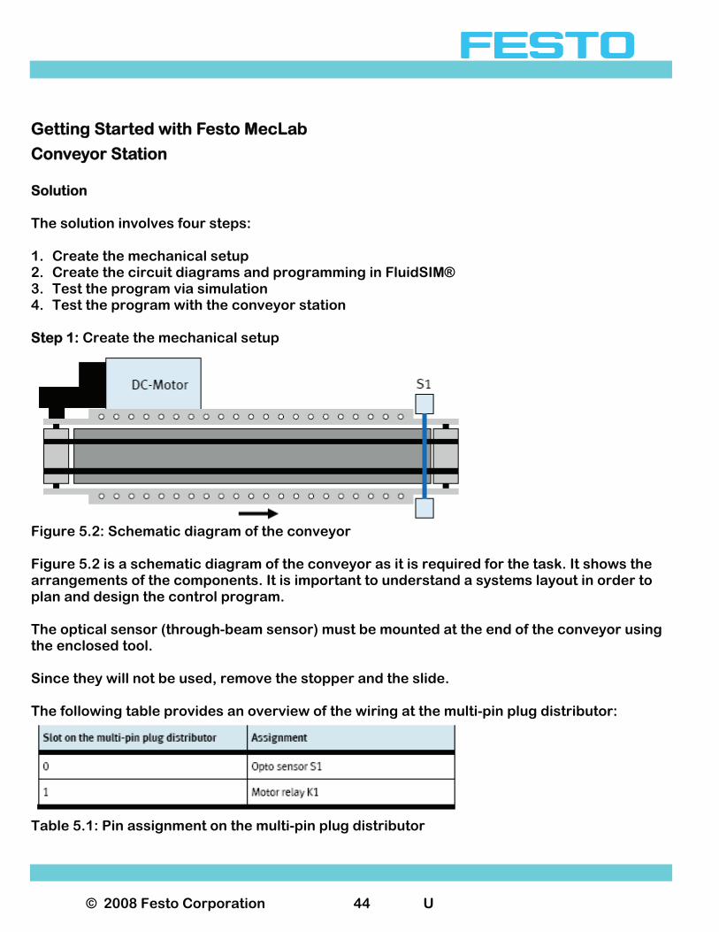
Conveyor Station Solution The solution involves four steps: 1. Create the mechanical setup 2. Create the circuit diagrams and programming in FluidSIM® 3. Test the program via simulation 4. Test the program with the conveyor station Step 1: Create the mechanical setup
Figure 5.2: Schematic diagram of the conveyor Figure 5.2 is a schematic diagram of the conveyor as it is required for the task. It shows the arrangements of the components. It is important to understand a systems layout in order to plan and design the control program. The optical sensor (through-beam sensor) must be mounted at the end of the conveyor using the enclosed tool. Since they will not be used, remove the stopper and the slide. The following table provides an overview of the wiring at the multi-pin plug distributor:
Table 5.1: Pin assignment on the multi-pin plug distributor

© 2008 Festo Corporation 45 U
Getting Started with Festo MecLab
Conveyor Station Note: In electrical circuit diagrams sensors are normally indicated with an "S" and relays with a "K". Step 2: Create the circuit diagrams and programming in FluidSIM® − Launch FluidSIM® − Double-click with the left mouse button on the FluidSIM® icon to access the start page of
the program. − Click on "File > New" to open the actual workspace. Select and place the required components. All required components are located in the com-ponent library. The library is divided into the following areas: − Pneumatics − Electrics − Digital technology − EasyPort − Miscellaneous In this exercise the required components will be selected from the "Electrics" and "Digital technology" section of the component library. Left-click on the appropriate section (this opens the folder) and then left-click and hold on the desired component symbol. Drag the symbol to the workspace and release the left mouse button. The following table provides an overview of some of the components in FluidSIM®.
© 2008 Festo Corporation 46 U
Getting Started with Festo MecLab
Conveyor Station
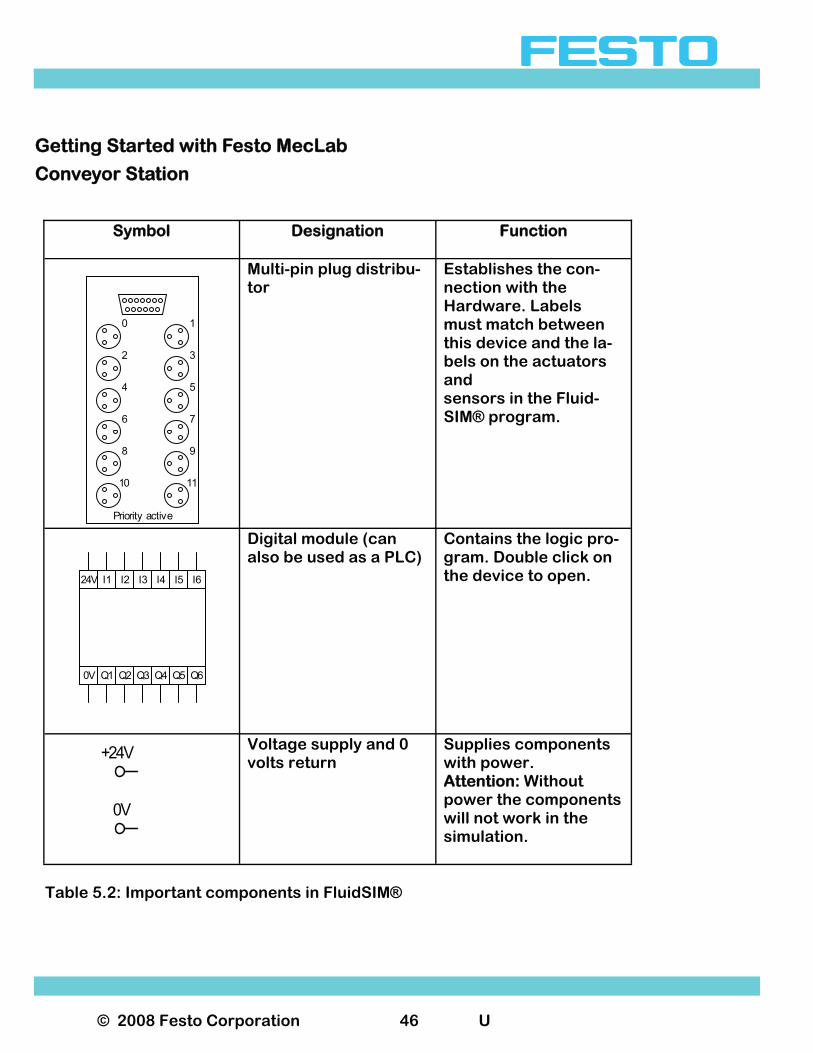
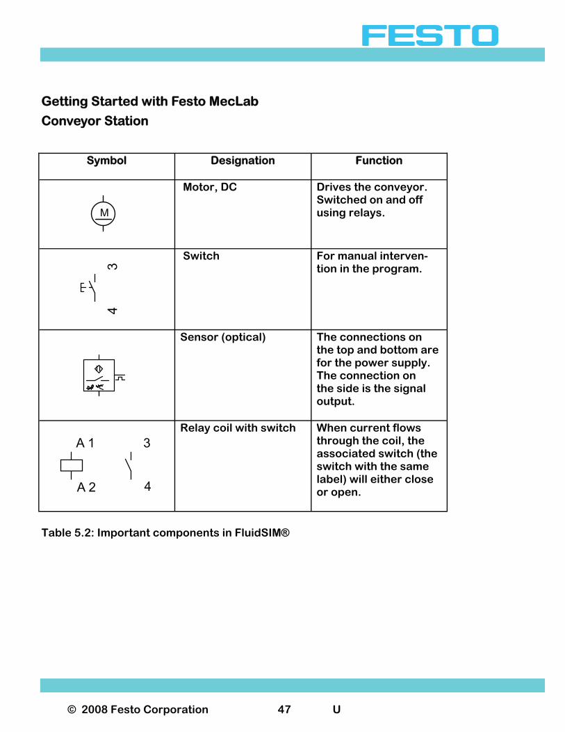
Table 5.2: Important components in FluidSIM®
Symbol
Designation
Function
Multi-pin plug distribu-tor
Establishes the con-nection with the Hardware. Labels must match between this device and the la-bels on the actuators and sensors in the Fluid-SIM® program.
Digital module (can also be used as a PLC)
Contains the logic pro-gram. Double click on the device to open.
Voltage supply and 0 volts return
Supplies components with power. Attention: Without power the components will not work in the simulation.
0V Q1 Q2 Q3 Q4 Q5 Q6
24V I1 I2 I3 I4 I5 I6
0
2
4
6
8
10
1
3
5
7
9
11
Priority active
0V
+24V
© 2008 Festo Corporation 47 U
Getting Started with Festo MecLab
Conveyor Station
Table 5.2: Important components in FluidSIM®
Symbol
Designation
Function
Motor, DC Drives the conveyor. Switched on and off using relays.
Switch For manual interven-tion in the program.
Sensor (optical) The connections on the top and bottom are for the power supply. The connection on the side is the signal output.
Relay coil with switch
When current flows through the coil, the associated switch (the switch with the same label) will either close or open.
M
34
3
4
A 1
A 2
© 2008 Festo Corporation 48 U
Getting Started with Festo MecLab
Conveyor Station
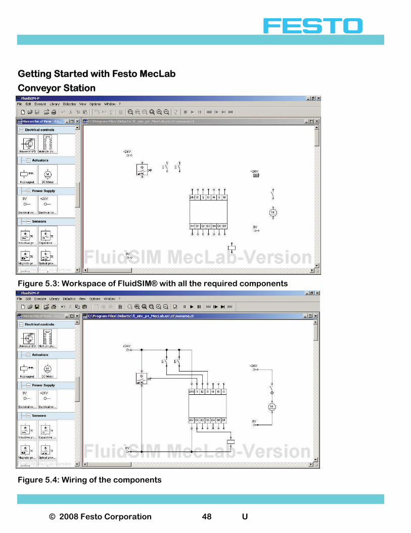
Figure 5.3: Workspace of FluidSIM® with all the required components
Figure 5.4: Wiring of the components
© 2008 Festo Corporation 49 U
Getting Started with Festo MecLab
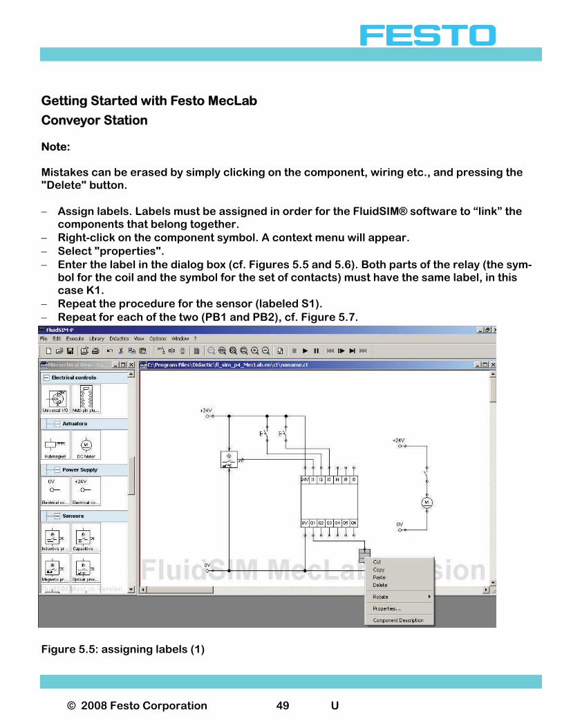
Conveyor Station Note: Mistakes can be erased by simply clicking on the component, wiring etc., and pressing the "Delete" button. − Assign labels. Labels must be assigned in order for the FluidSIM® software to “link” the
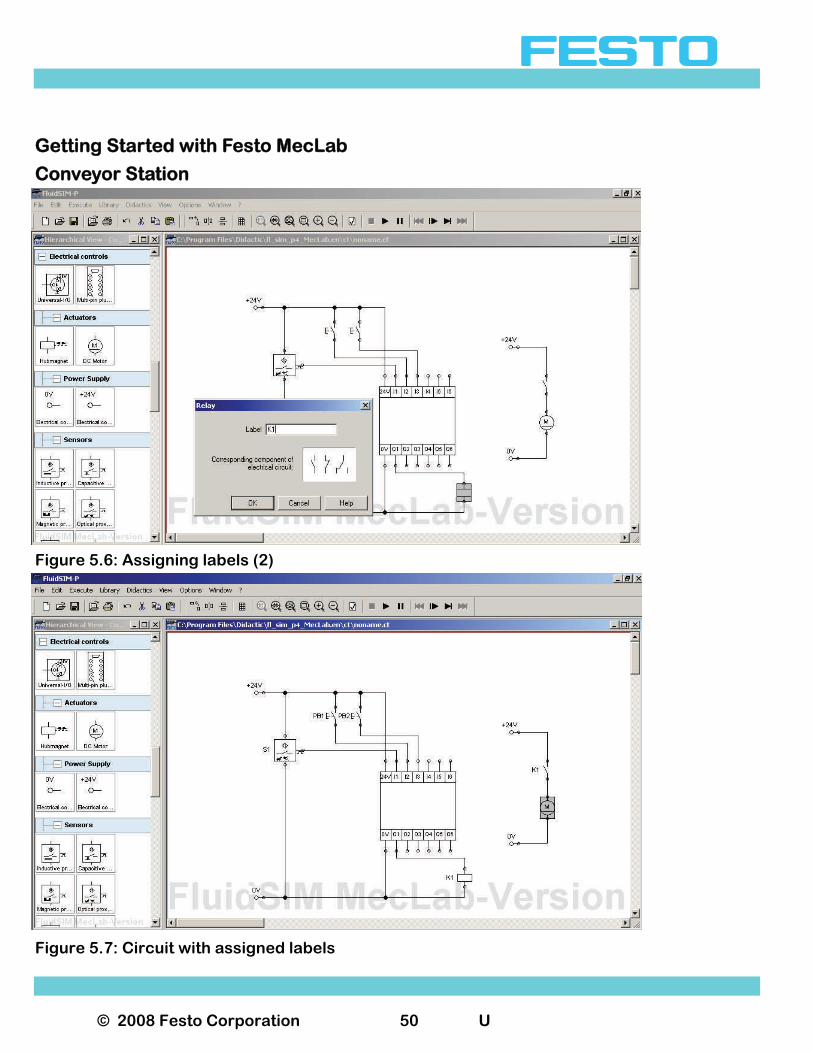
components that belong together. − Right-click on the component symbol. A context menu will appear. − Select "properties". − Enter the label in the dialog box (cf. Figures 5.5 and 5.6). Both parts of the relay (the sym-
bol for the coil and the symbol for the set of contacts) must have the same label, in this case K1.
− Repeat the procedure for the sensor (labeled S1). − Repeat for each of the two (PB1 and PB2), cf. Figure 5.7.
Figure 5.5: assigning labels (1)
© 2008 Festo Corporation 50 U
Getting Started with Festo MecLab
Conveyor Station
Figure 5.6: Assigning labels (2)
Figure 5.7: Circuit with assigned labels
© 2008 Festo Corporation 51 U
Getting Started with Festo MecLab
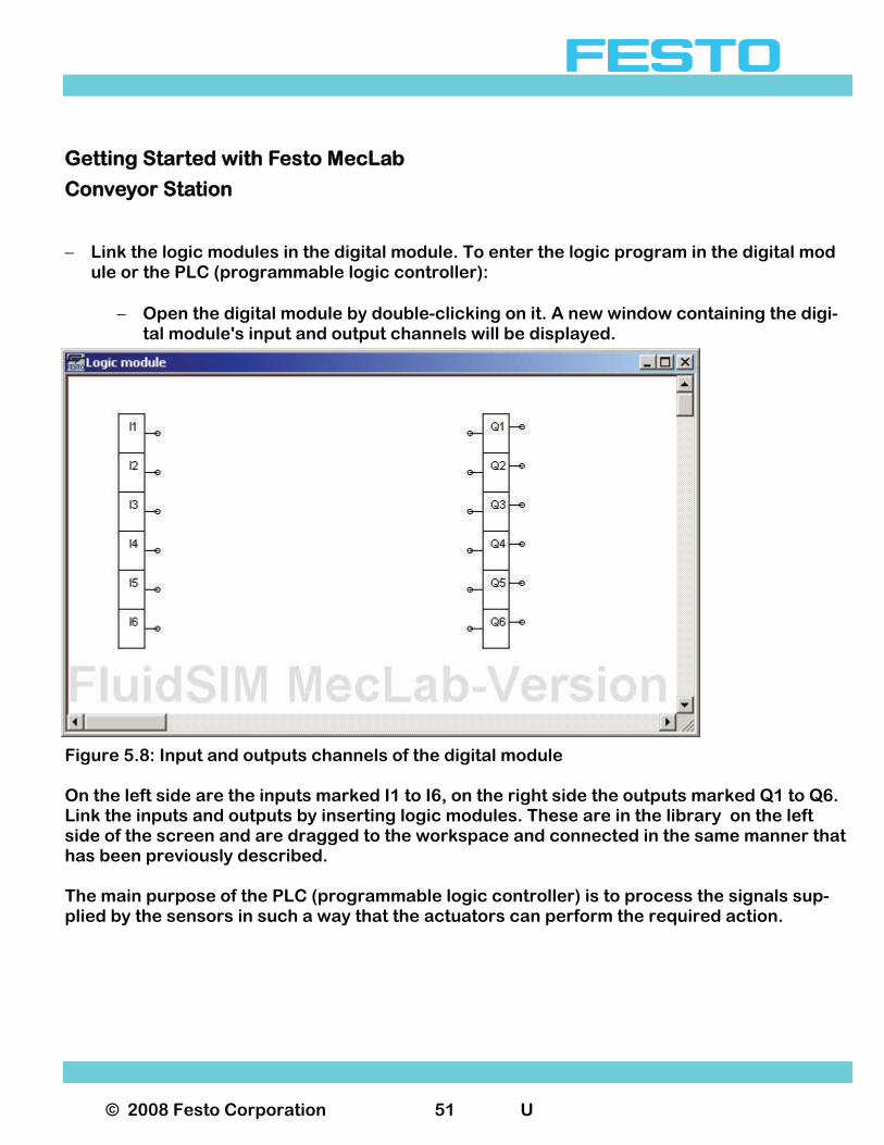
Conveyor Station − Link the logic modules in the digital module. To enter the logic program in the digital mod ule or the PLC (programmable logic controller):
− Open the digital module by double-clicking on it. A new window containing the digi-
tal module's input and output channels will be displayed.
Figure 5.8: Input and outputs channels of the digital module On the left side are the inputs marked I1 to I6, on the right side the outputs marked Q1 to Q6. Link the inputs and outputs by inserting logic modules. These are in the library on the left side of the screen and are dragged to the workspace and connected in the same manner that has been previously described. The main purpose of the PLC (programmable logic controller) is to process the signals sup-plied by the sensors in such a way that the actuators can perform the required action.
© 2008 Festo Corporation 52 U
Getting Started with Festo MecLab
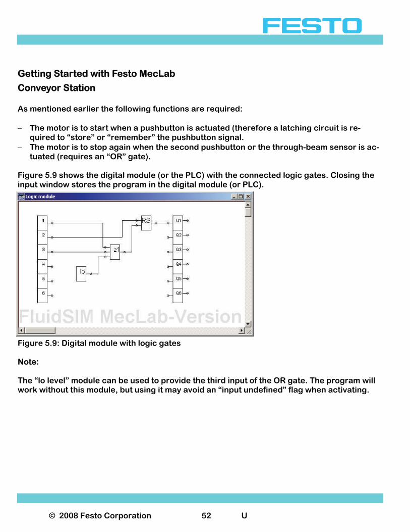
Conveyor Station As mentioned earlier the following functions are required: − The motor is to start when a pushbutton is actuated (therefore a latching circuit is re-
quired to “store” or “remember” the pushbutton signal. − The motor is to stop again when the second pushbutton or the through-beam sensor is ac-
tuated (requires an “OR” gate). Figure 5.9 shows the digital module (or the PLC) with the connected logic gates. Closing the input window stores the program in the digital module (or PLC).
Figure 5.9: Digital module with logic gates Note: The “lo level” module can be used to provide the third input of the OR gate. The program will work without this module, but using it may avoid an “input undefined” flag when activating.
© 2008 Festo Corporation 53 U
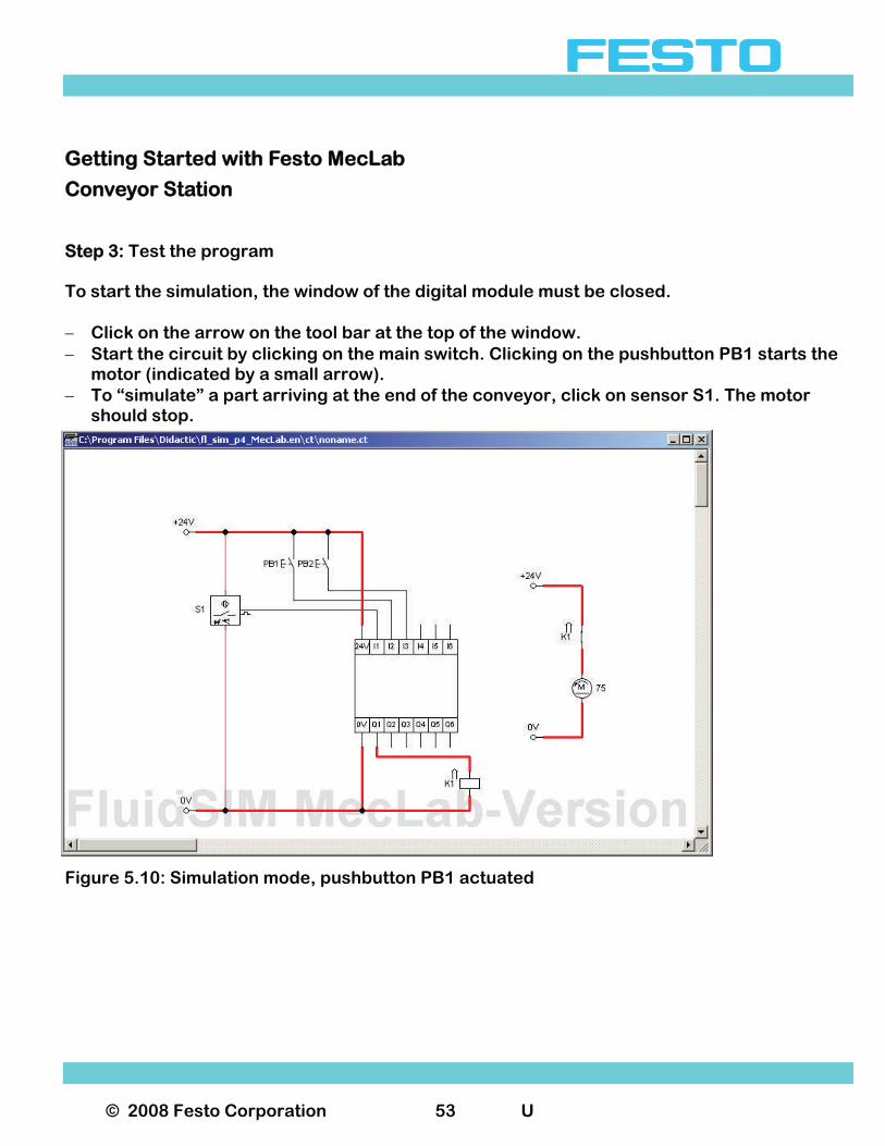
Getting Started with Festo MecLab
Conveyor Station Step 3: Test the program To start the simulation, the window of the digital module must be closed. − Click on the arrow on the tool bar at the top of the window. − Start the circuit by clicking on the main switch. Clicking on the pushbutton PB1 starts the
motor (indicated by a small arrow). − To “simulate” a part arriving at the end of the conveyor, click on sensor S1. The motor should stop.
Figure 5.10: Simulation mode, pushbutton PB1 actuated
© 2008 Festo Corporation 54 U
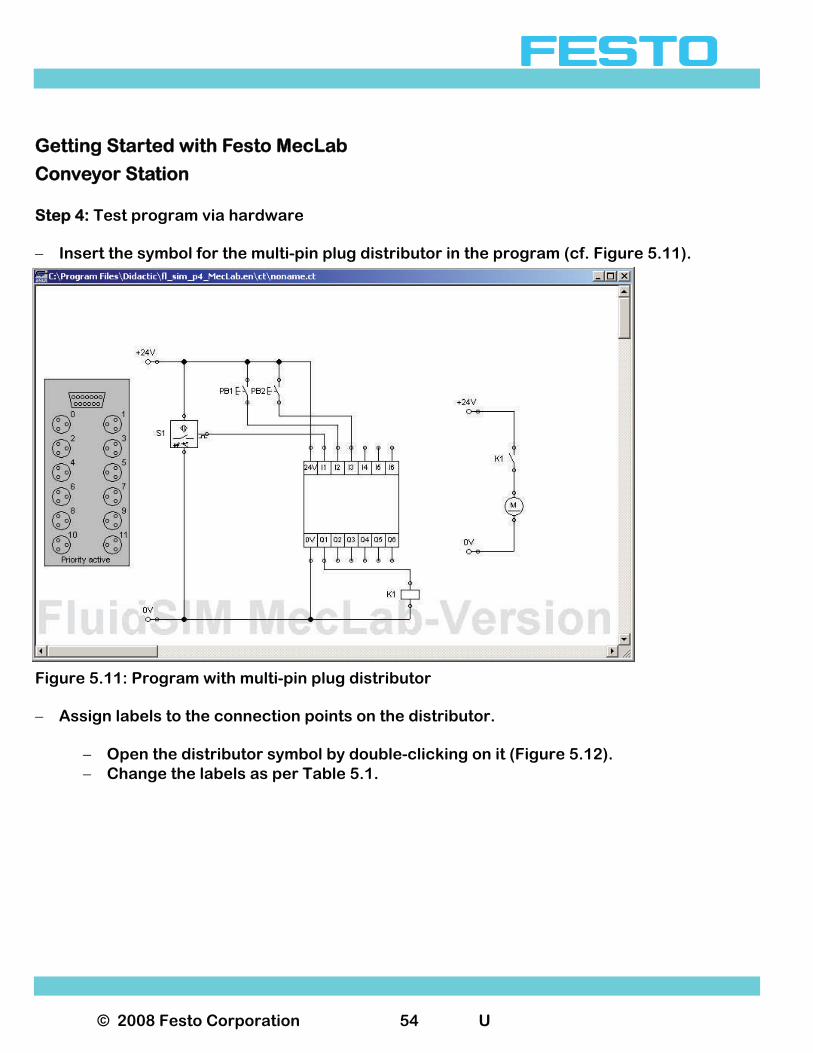
Getting Started with Festo MecLab
Conveyor Station Step 4: Test program via hardware − Insert the symbol for the multi-pin plug distributor in the program (cf. Figure 5.11).
Figure 5.11: Program with multi-pin plug distributor − Assign labels to the connection points on the distributor.
− Open the distributor symbol by double-clicking on it (Figure 5.12). − Change the labels as per Table 5.1.
© 2008 Festo Corporation 55 U
Getting Started with Festo MecLab
Conveyor Station
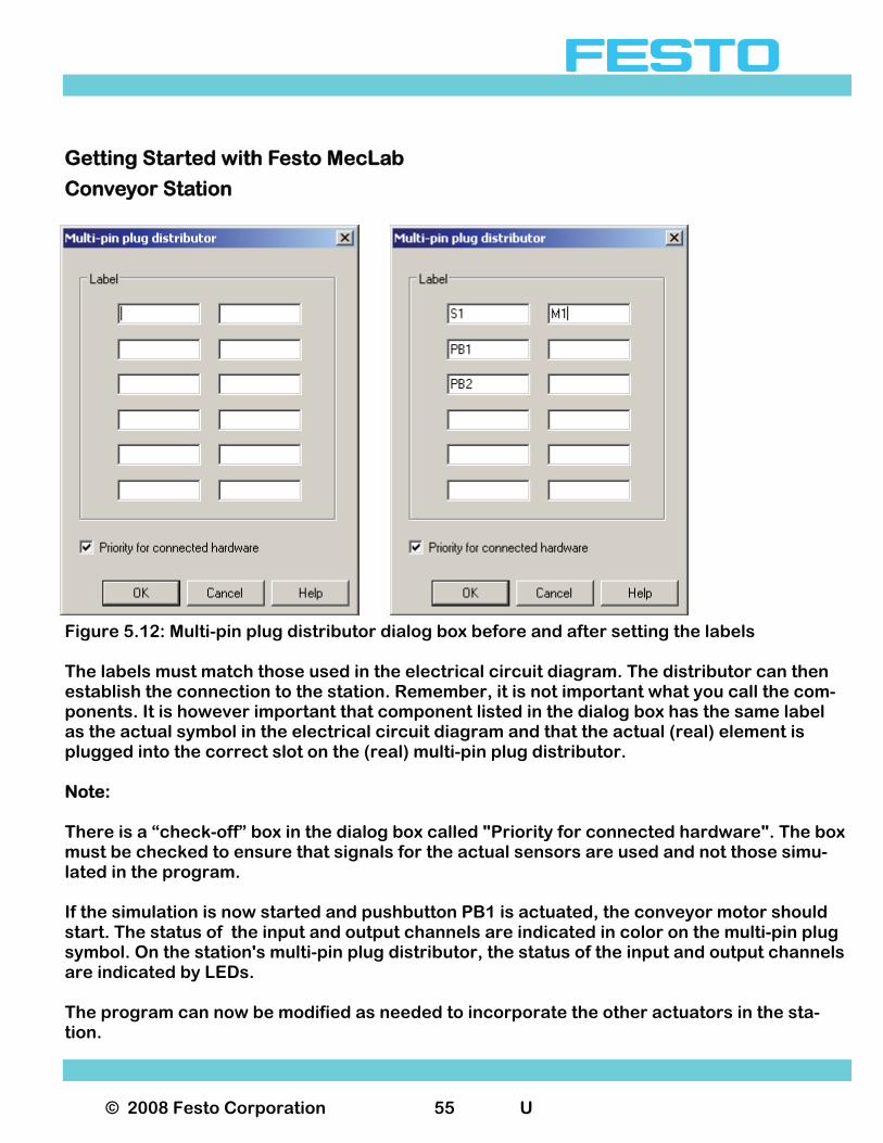
Figure 5.12: Multi-pin plug distributor dialog box before and after setting the labels The labels must match those used in the electrical circuit diagram. The distributor can then establish the connection to the station. Remember, it is not important what you call the com-ponents. It is however important that component listed in the dialog box has the same label as the actual symbol in the electrical circuit diagram and that the actual (real) element is plugged into the correct slot on the (real) multi-pin plug distributor. Note: There is a “check-off” box in the dialog box called "Priority for connected hardware". The box must be checked to ensure that signals for the actual sensors are used and not those simu-lated in the program. If the simulation is now started and pushbutton PB1 is actuated, the conveyor motor should start. The status of the input and output channels are indicated in color on the multi-pin plug symbol. On the station's multi-pin plug distributor, the status of the input and output channels are indicated by LEDs. The program can now be modified as needed to incorporate the other actuators in the sta-tion.
© 2008 Festo Corporation 56 U
Getting Started with Festo MecLab
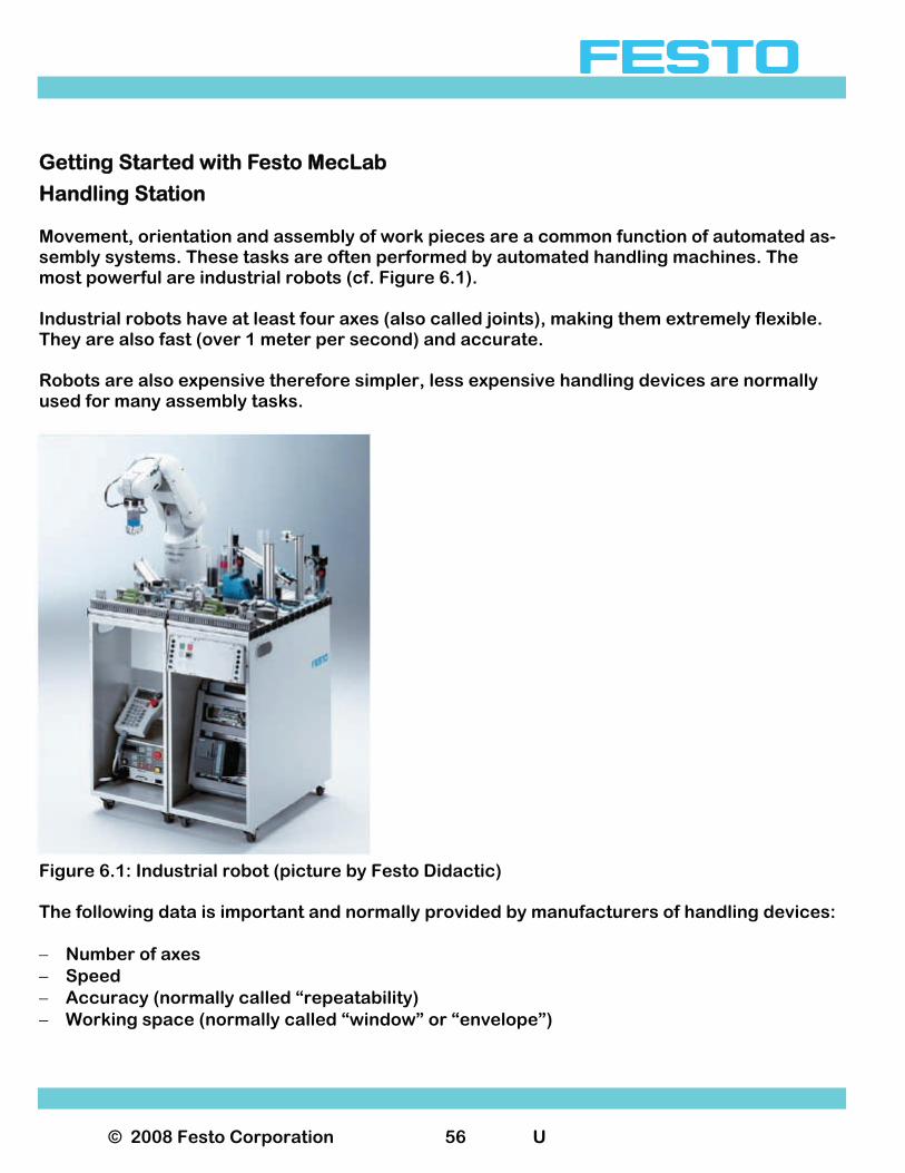
Handling Station Movement, orientation and assembly of work pieces are a common function of automated as-sembly systems. These tasks are often performed by automated handling machines. The most powerful are industrial robots (cf. Figure 6.1). Industrial robots have at least four axes (also called joints), making them extremely flexible. They are also fast (over 1 meter per second) and accurate. Robots are also expensive therefore simpler, less expensive handling devices are normally used for many assembly tasks.
Figure 6.1: Industrial robot (picture by Festo Didactic) The following data is important and normally provided by manufacturers of handling devices: − Number of axes − Speed − Accuracy (normally called “repeatability) − Working space (normally called “window” or “envelope”)
© 2008 Festo Corporation 57 U
Getting Started with Festo MecLab
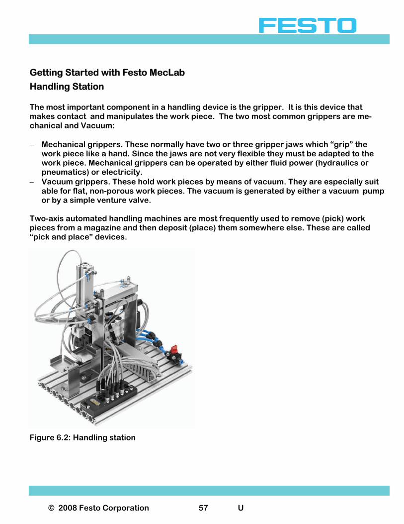
Handling Station The most important component in a handling device is the gripper. It is this device that makes contact and manipulates the work piece. The two most common grippers are me-chanical and Vacuum: − Mechanical grippers. These normally have two or three gripper jaws which “grip” the
work piece like a hand. Since the jaws are not very flexible they must be adapted to the work piece. Mechanical grippers can be operated by either fluid power (hydraulics or pneumatics) or electricity.
− Vacuum grippers. These hold work pieces by means of vacuum. They are especially suit able for flat, non-porous work pieces. The vacuum is generated by either a vacuum pump or by a simple venture valve. Two-axis automated handling machines are most frequently used to remove (pick) work pieces from a magazine and then deposit (place) them somewhere else. These are called “pick and place” devices.
Figure 6.2: Handling station
© 2008 Festo Corporation 58 U
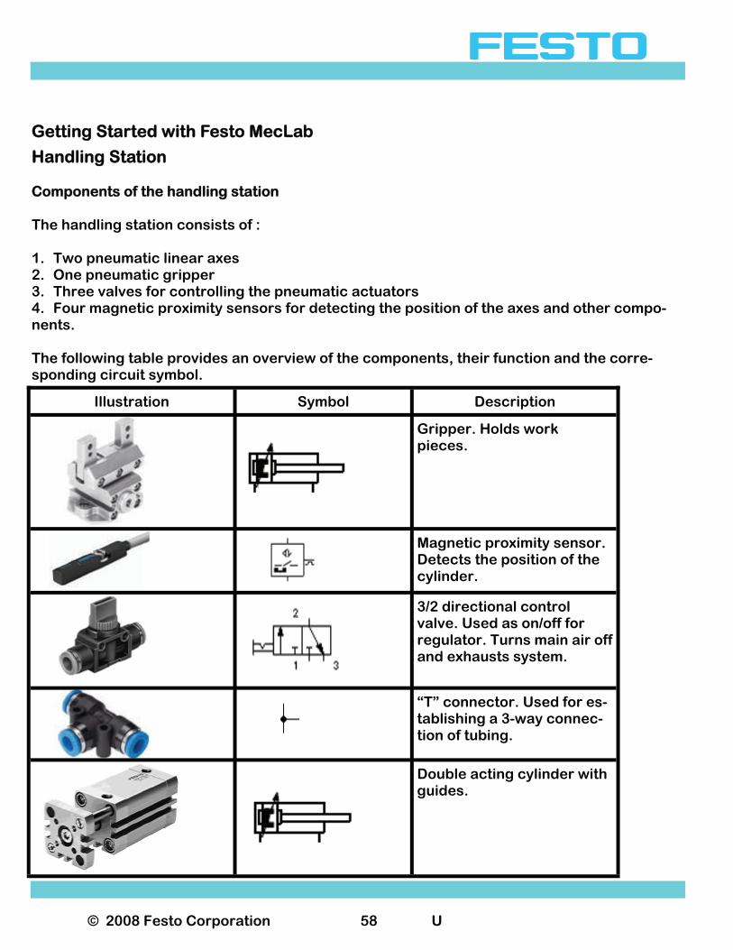
Getting Started with Festo MecLab
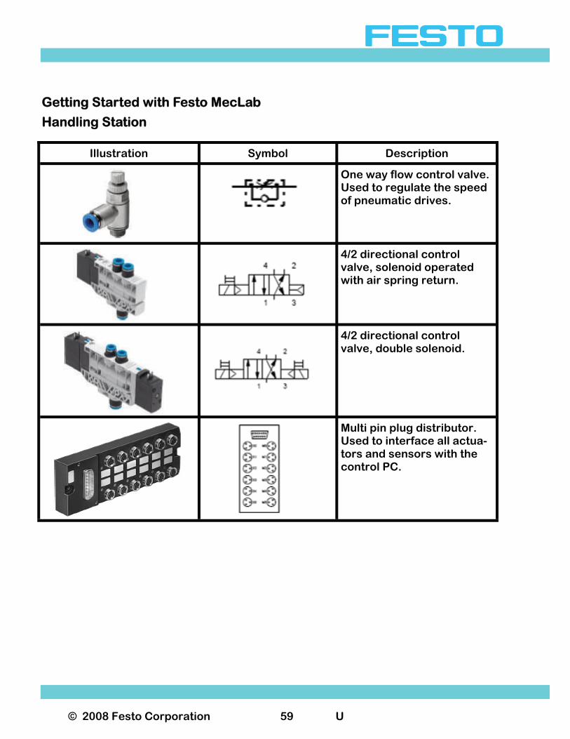
Handling Station Components of the handling station The handling station consists of : 1. Two pneumatic linear axes 2. One pneumatic gripper 3. Three valves for controlling the pneumatic actuators 4. Four magnetic proximity sensors for detecting the position of the axes and other compo-nents. The following table provides an overview of the components, their function and the corre-sponding circuit symbol.
Illustration Symbol Description
Gripper. Holds work pieces.
Magnetic proximity sensor. Detects the position of the cylinder.
3/2 directional control valve. Used as on/off for regulator. Turns main air off and exhausts system.
“T” connector. Used for es-tablishing a 3-way connec-tion of tubing.
Double acting cylinder with guides.
© 2008 Festo Corporation 59 U
Getting Started with Festo MecLab
Handling Station
Illustration Symbol Description
One way flow control valve. Used to regulate the speed of pneumatic drives.
4/2 directional control valve, solenoid operated with air spring return.
4/2 directional control valve, double solenoid.
Multi pin plug distributor. Used to interface all actua-tors and sensors with the control PC.
© 2008 Festo Corporation 60 U
Getting Started with Festo MecLab
Handling Station Commissioning the handling station The handling station consists of a two-axis handling device that can perform simple assembly tasks. The handling station can perform several tasks: 1. Transferring a work piece 2. Joining the base and lid 3. Sorting or assembly functions in conjunction with other MecLab® stations. The handling station uses a mechanical two-jaw gripper that has been adapted to the cylindrical work piece. This gripper can be exchanged for a vacuum gripper that is avail-able as an accessory. The handling station is supplied fully assembled. It may be necessary to readjust the place holders of the work piece so that the gripper is aligned properly. An aluminum profile plate is used as the base on which modules are mounted. T-head nuts are used to secure the modules to the plate. All modules and components can be disassembled and assembled using the supplied tools. Flow control valves can be adjusted with the supplied screwdriver. There is also a tubing cut-ter used to cut the pneumatic tubing at a square angle (do not use scissors or knives). The handling system must be connected to the USB port of the PC using the EasyPort and the 24V power supply should be connected as described in Section 3. Correct wiring of the actuators and sensors must be ensured in order for the supplied sample programs to operate the system. Pin assignments are described in a schematic diagram in the sample program.
© 2008 Festo Corporation 61 U
Getting Started with Festo MecLab
Handling Station Executing a simple task using the handling station In a production line, the handling station often carries work pieces between two stations. The following sample exercise explains the step by-step operation of the FluidSIM® software as well as its interaction with the handling station: Task: 1. Develop a computer-aided manual control with the following functions:
a. Advance the x-axis when a pushbutton is actuated, but only if the cylinder is in the retracted position.
b. Retract the x-axis when a pushbutton is actuated, but only if the cylinder is in the ex-tended position.
Procedure for solving the task: The solution to this task can be broken down into five phases: 1. Initial considerations and schematic diagram 2. Assignment tables for the components 3. Circuit diagram creation and programming using FluidSIM® 4. Testing with FluidSIM® via simulation 5. Testing the program on the actual handling station
© 2008 Festo Corporation 62 U
Getting Started with Festo MecLab
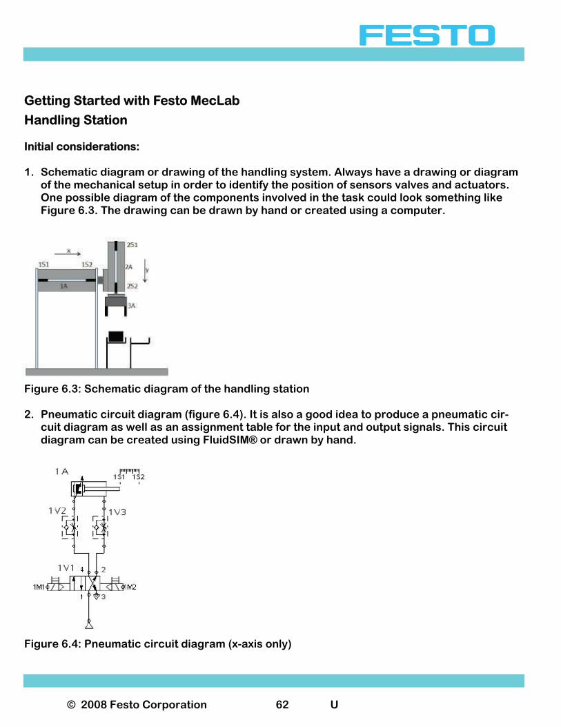
Handling Station Initial considerations: 1. Schematic diagram or drawing of the handling system. Always have a drawing or diagram
of the mechanical setup in order to identify the position of sensors valves and actuators. One possible diagram of the components involved in the task could look something like Figure 6.3. The drawing can be drawn by hand or created using a computer.
Figure 6.3: Schematic diagram of the handling station 2. Pneumatic circuit diagram (figure 6.4). It is also a good idea to produce a pneumatic cir-
cuit diagram as well as an assignment table for the input and output signals. This circuit diagram can be created using FluidSIM® or drawn by hand.
Figure 6.4: Pneumatic circuit diagram (x-axis only)
© 2008 Festo Corporation 63 U
Getting Started with Festo MecLab
Handling Station
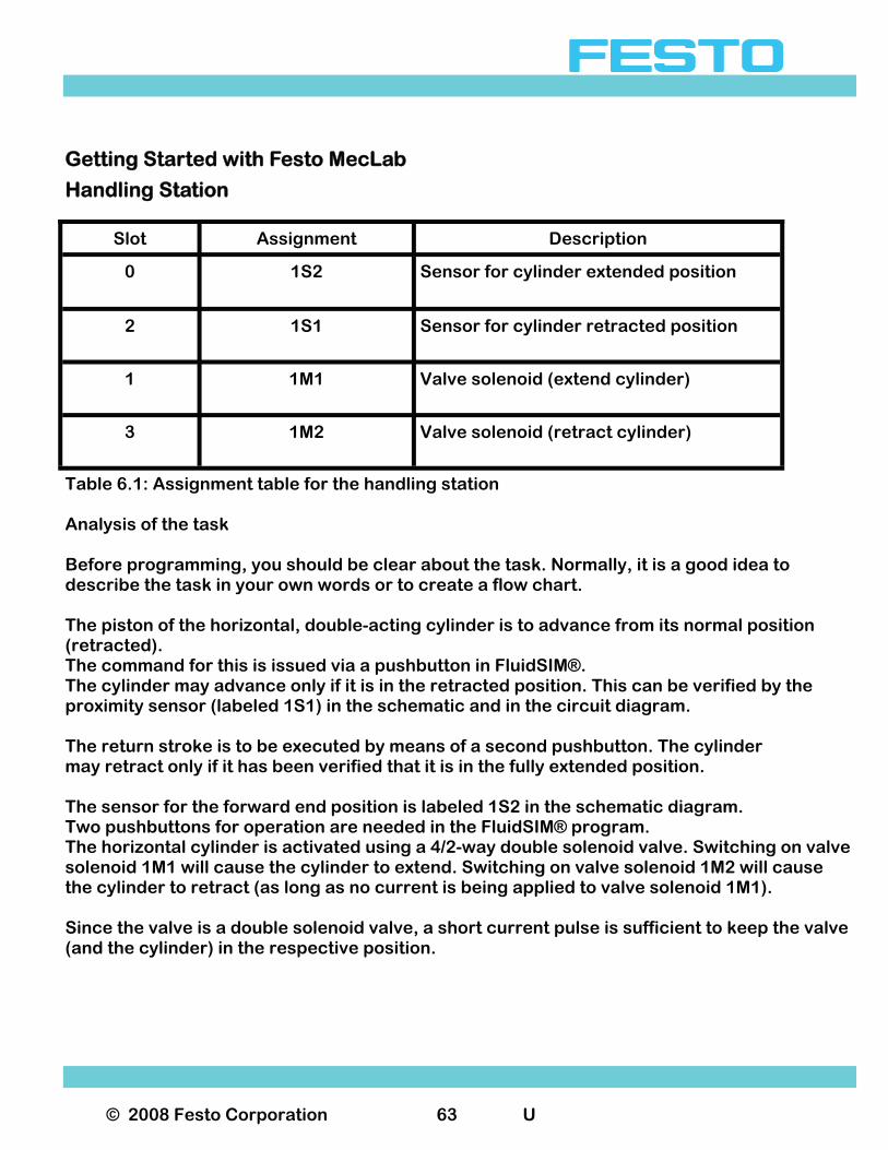
Table 6.1: Assignment table for the handling station Analysis of the task Before programming, you should be clear about the task. Normally, it is a good idea to describe the task in your own words or to create a flow chart. The piston of the horizontal, double-acting cylinder is to advance from its normal position (retracted). The command for this is issued via a pushbutton in FluidSIM®. The cylinder may advance only if it is in the retracted position. This can be verified by the proximity sensor (labeled 1S1) in the schematic and in the circuit diagram. The return stroke is to be executed by means of a second pushbutton. The cylinder may retract only if it has been verified that it is in the fully extended position. The sensor for the forward end position is labeled 1S2 in the schematic diagram. Two pushbuttons for operation are needed in the FluidSIM® program. The horizontal cylinder is activated using a 4/2-way double solenoid valve. Switching on valve solenoid 1M1 will cause the cylinder to extend. Switching on valve solenoid 1M2 will cause the cylinder to retract (as long as no current is being applied to valve solenoid 1M1). Since the valve is a double solenoid valve, a short current pulse is sufficient to keep the valve (and the cylinder) in the respective position.
Slot Assignment Description
0 1S2 Sensor for cylinder extended position
2 1S1 Sensor for cylinder retracted position
1 1M1 Valve solenoid (extend cylinder)
3 1M2 Valve solenoid (retract cylinder)
© 2008 Festo Corporation 64 U
Getting Started with Festo MecLab
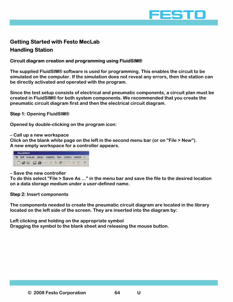
Handling Station Circuit diagram creation and programming using FluidSIM® The supplied FluidSIM® software is used for programming. This enables the circuit to be simulated on the computer. If the simulation does not reveal any errors, then the station can be directly activated and operated with the program. Since the test setup consists of electrical and pneumatic components, a circuit plan must be created in FluidSIM® for both system components. We recommended that you create the pneumatic circuit diagram first and then the electrical circuit diagram. Step 1: Opening FluidSIM® Opened by double-clicking on the program icon: – Call up a new workspace Click on the blank white page on the left in the second menu bar (or on "File > New"). A new empty workspace for a controller appears.
– Save the new controller To do this select "File > Save As ..." in the menu bar and save the file to the desired location on a data storage medium under a user-defined name. Step 2: Insert components The components needed to create the pneumatic circuit diagram are located in the library located on the left side of the screen. They are inserted into the diagram by: Left clicking and holding on the appropriate symbol Dragging the symbol to the blank sheet and releasing the mouse button.
© 2008 Festo Corporation 65 U
Getting Started with Festo MecLab
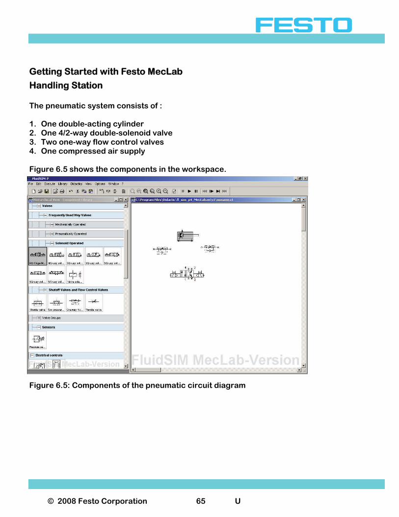
Handling Station The pneumatic system consists of : 1. One double-acting cylinder 2. One 4/2-way double-solenoid valve 3. Two one-way flow control valves 4. One compressed air supply Figure 6.5 shows the components in the workspace.
Figure 6.5: Components of the pneumatic circuit diagram
© 2008 Festo Corporation 66 U
Getting Started with Festo MecLab
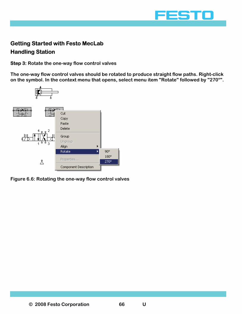
Handling Station Step 3: Rotate the one-way flow control valves The one-way flow control valves should be rotated to produce straight flow paths. Right-click on the symbol. In the context menu that opens, select menu item "Rotate" followed by "270°".
Figure 6.6: Rotating the one-way flow control valves
© 2008 Festo Corporation 67 U
Getting Started with Festo MecLab
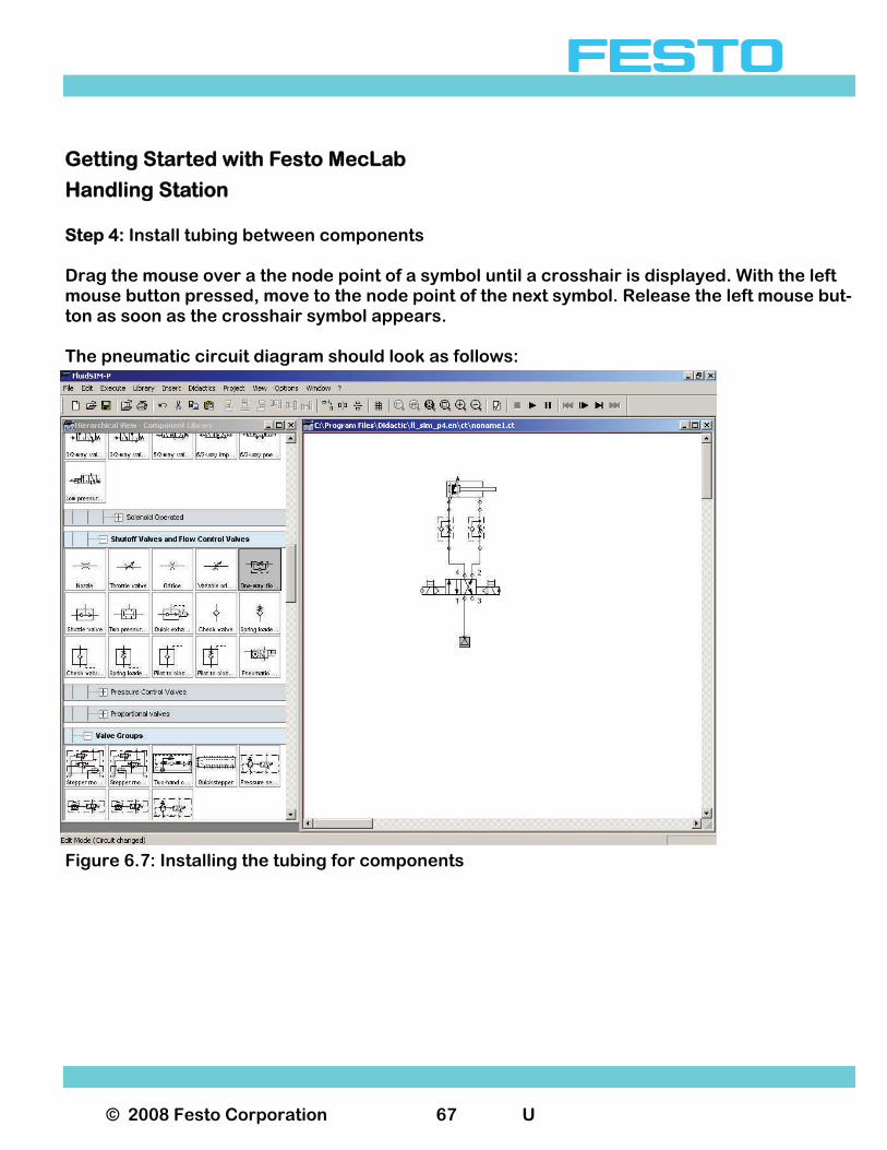
Handling Station Step 4: Install tubing between components Drag the mouse over a the node point of a symbol until a crosshair is displayed. With the left mouse button pressed, move to the node point of the next symbol. Release the left mouse but-ton as soon as the crosshair symbol appears. The pneumatic circuit diagram should look as follows:
Figure 6.7: Installing the tubing for components
© 2008 Festo Corporation 68 U
Getting Started with Festo MecLab
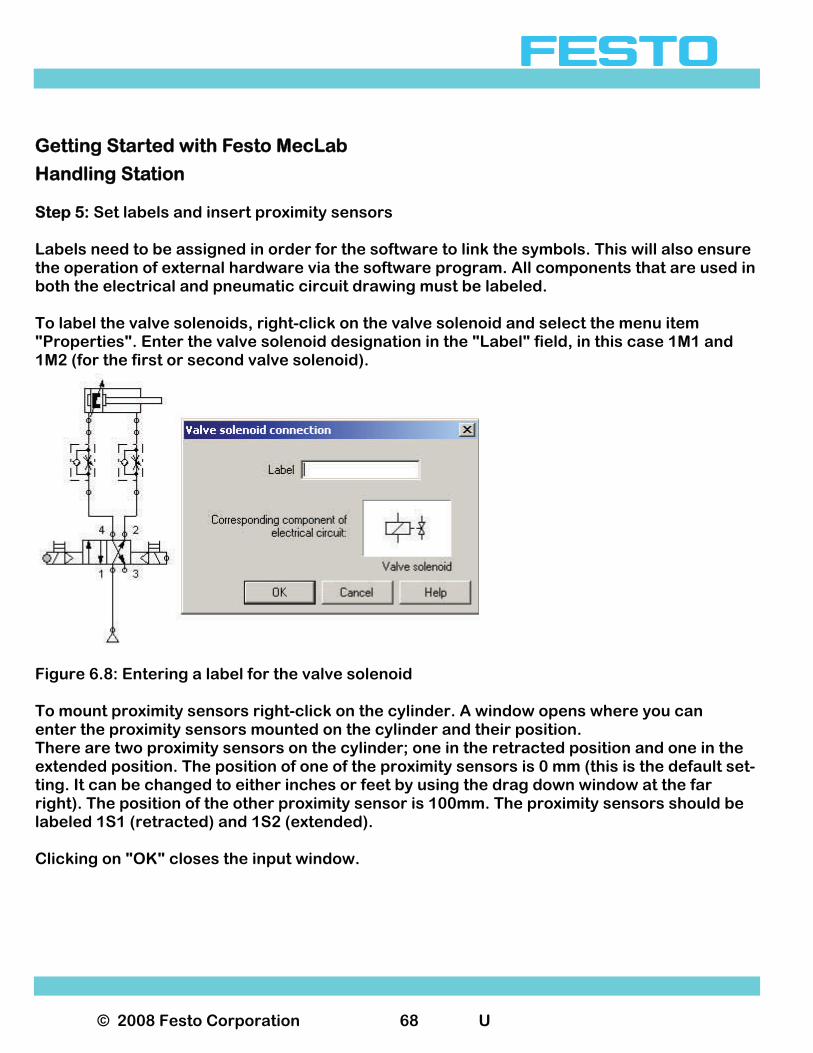
Handling Station Step 5: Set labels and insert proximity sensors Labels need to be assigned in order for the software to link the symbols. This will also ensure the operation of external hardware via the software program. All components that are used in both the electrical and pneumatic circuit drawing must be labeled. To label the valve solenoids, right-click on the valve solenoid and select the menu item "Properties". Enter the valve solenoid designation in the "Label" field, in this case 1M1 and 1M2 (for the first or second valve solenoid).
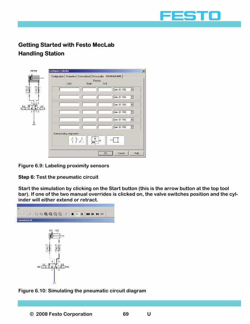
Figure 6.8: Entering a label for the valve solenoid To mount proximity sensors right-click on the cylinder. A window opens where you can enter the proximity sensors mounted on the cylinder and their position. There are two proximity sensors on the cylinder; one in the retracted position and one in the extended position. The position of one of the proximity sensors is 0 mm (this is the default set-ting. It can be changed to either inches or feet by using the drag down window at the far right). The position of the other proximity sensor is 100mm. The proximity sensors should be labeled 1S1 (retracted) and 1S2 (extended). Clicking on "OK" closes the input window.
© 2008 Festo Corporation 69 U
Getting Started with Festo MecLab
Handling Station
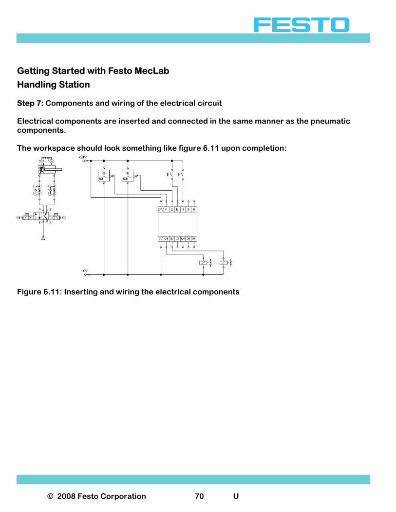
Figure 6.9: Labeling proximity sensors Step 6: Test the pneumatic circuit Start the simulation by clicking on the Start button (this is the arrow button at the top tool bar). If one of the two manual overrides is clicked on, the valve switches position and the cyl-inder will either extend or retract.
Figure 6.10: Simulating the pneumatic circuit diagram
© 2008 Festo Corporation 70 U
Getting Started with Festo MecLab
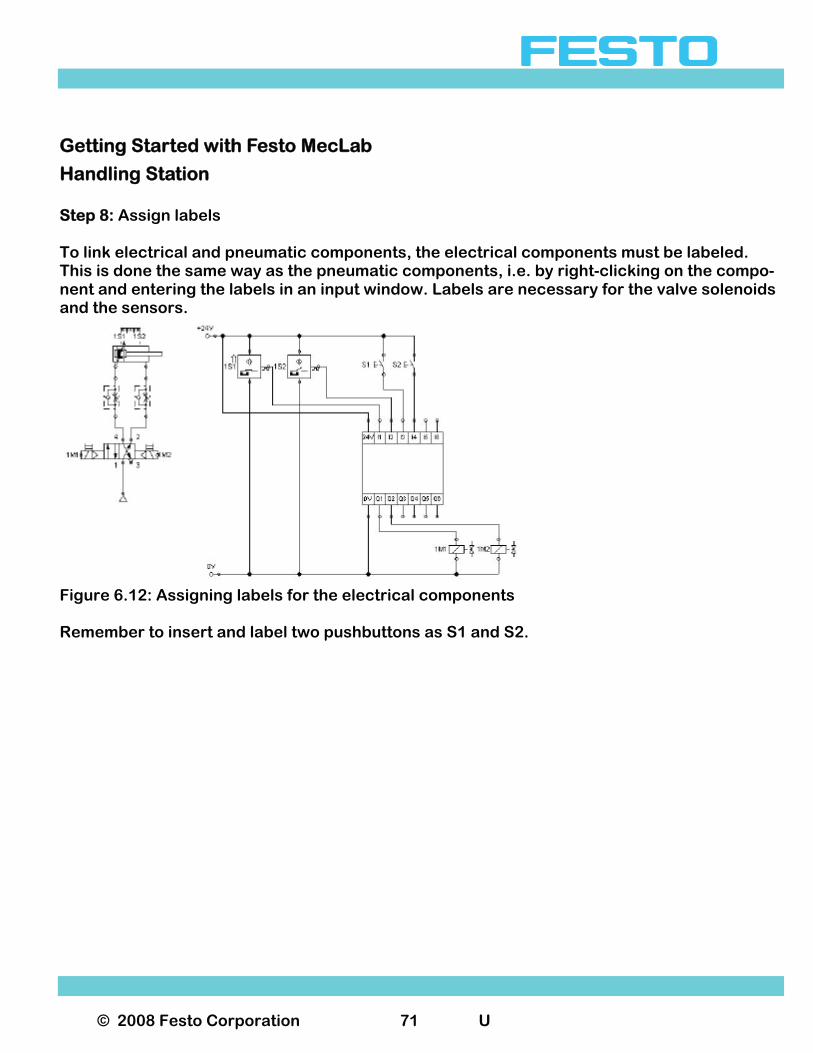
Handling Station Step 7: Components and wiring of the electrical circuit Electrical components are inserted and connected in the same manner as the pneumatic components. The workspace should look something like figure 6.11 upon completion:
Figure 6.11: Inserting and wiring the electrical components
© 2008 Festo Corporation 71 U
Getting Started with Festo MecLab
Handling Station Step 8: Assign labels To link electrical and pneumatic components, the electrical components must be labeled. This is done the same way as the pneumatic components, i.e. by right-clicking on the compo-nent and entering the labels in an input window. Labels are necessary for the valve solenoids and the sensors.
Figure 6.12: Assigning labels for the electrical components Remember to insert and label two pushbuttons as S1 and S2.
© 2008 Festo Corporation 72 U
Getting Started with Festo MecLab
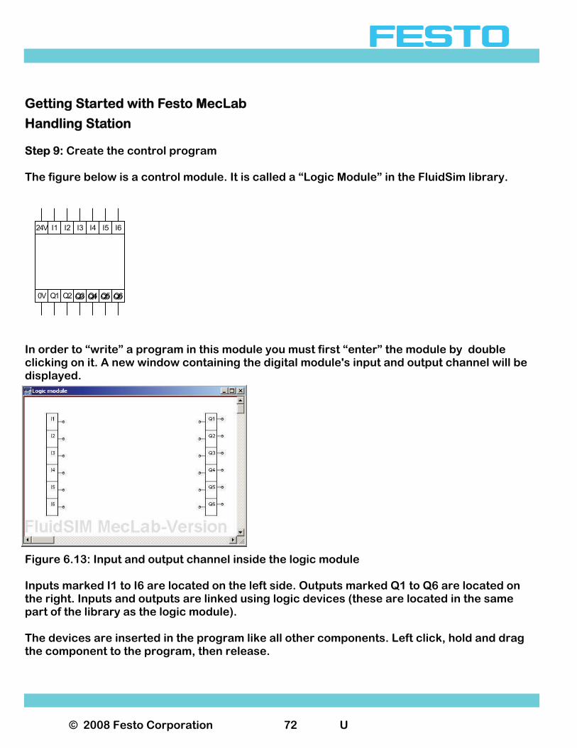
Handling Station Step 9: Create the control program The figure below is a control module. It is called a “Logic Module” in the FluidSim library.
In order to “write” a program in this module you must first “enter” the module by double clicking on it. A new window containing the digital module's input and output channel will be displayed.
Figure 6.13: Input and output channel inside the logic module Inputs marked I1 to I6 are located on the left side. Outputs marked Q1 to Q6 are located on the right. Inputs and outputs are linked using logic devices (these are located in the same part of the library as the logic module). The devices are inserted in the program like all other components. Left click, hold and drag the component to the program, then release.
Q3 Q4 Q5 Q60V Q1 Q2 Q3 Q4 Q5 Q6
24V I1 I2 I3 I4 I5 I6
© 2008 Festo Corporation 73 U
Getting Started with Festo MecLab
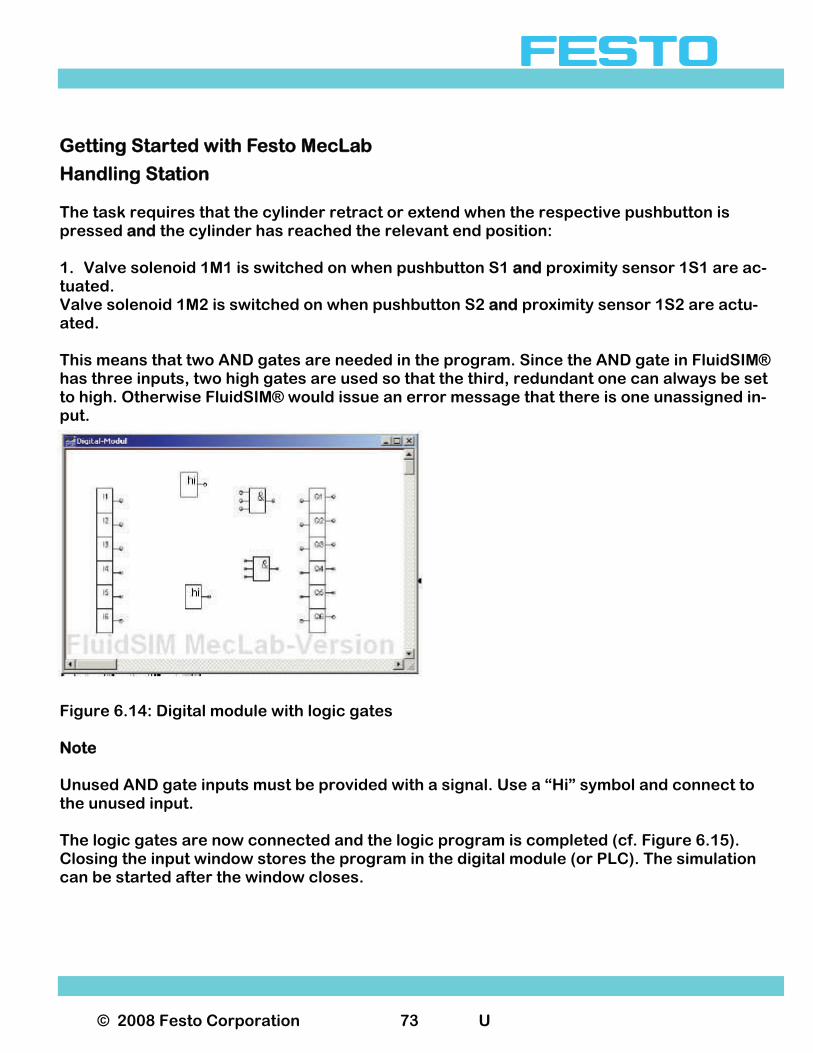
Handling Station The task requires that the cylinder retract or extend when the respective pushbutton is pressed and the cylinder has reached the relevant end position: 1. Valve solenoid 1M1 is switched on when pushbutton S1 and proximity sensor 1S1 are ac-tuated. Valve solenoid 1M2 is switched on when pushbutton S2 and proximity sensor 1S2 are actu-ated. This means that two AND gates are needed in the program. Since the AND gate in FluidSIM® has three inputs, two high gates are used so that the third, redundant one can always be set to high. Otherwise FluidSIM® would issue an error message that there is one unassigned in-put.
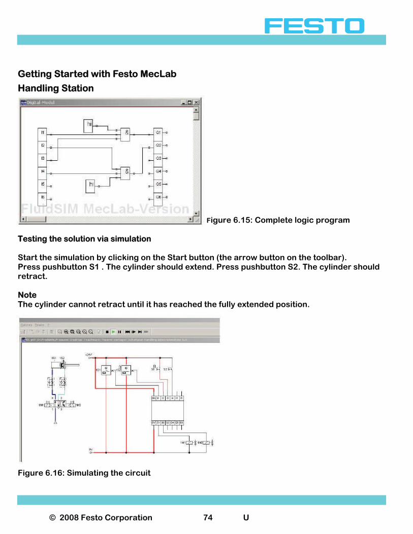
Figure 6.14: Digital module with logic gates Note Unused AND gate inputs must be provided with a signal. Use a “Hi” symbol and connect to the unused input. The logic gates are now connected and the logic program is completed (cf. Figure 6.15). Closing the input window stores the program in the digital module (or PLC). The simulation can be started after the window closes.
© 2008 Festo Corporation 74 U
Getting Started with Festo MecLab
Handling Station Figure 6.15: Complete logic program
Testing the solution via simulation Start the simulation by clicking on the Start button (the arrow button on the toolbar). Press pushbutton S1 . The cylinder should extend. Press pushbutton S2. The cylinder should retract. Note The cylinder cannot retract until it has reached the fully extended position.
Figure 6.16: Simulating the circuit
© 2008 Festo Corporation 75 U
Getting Started with Festo MecLab
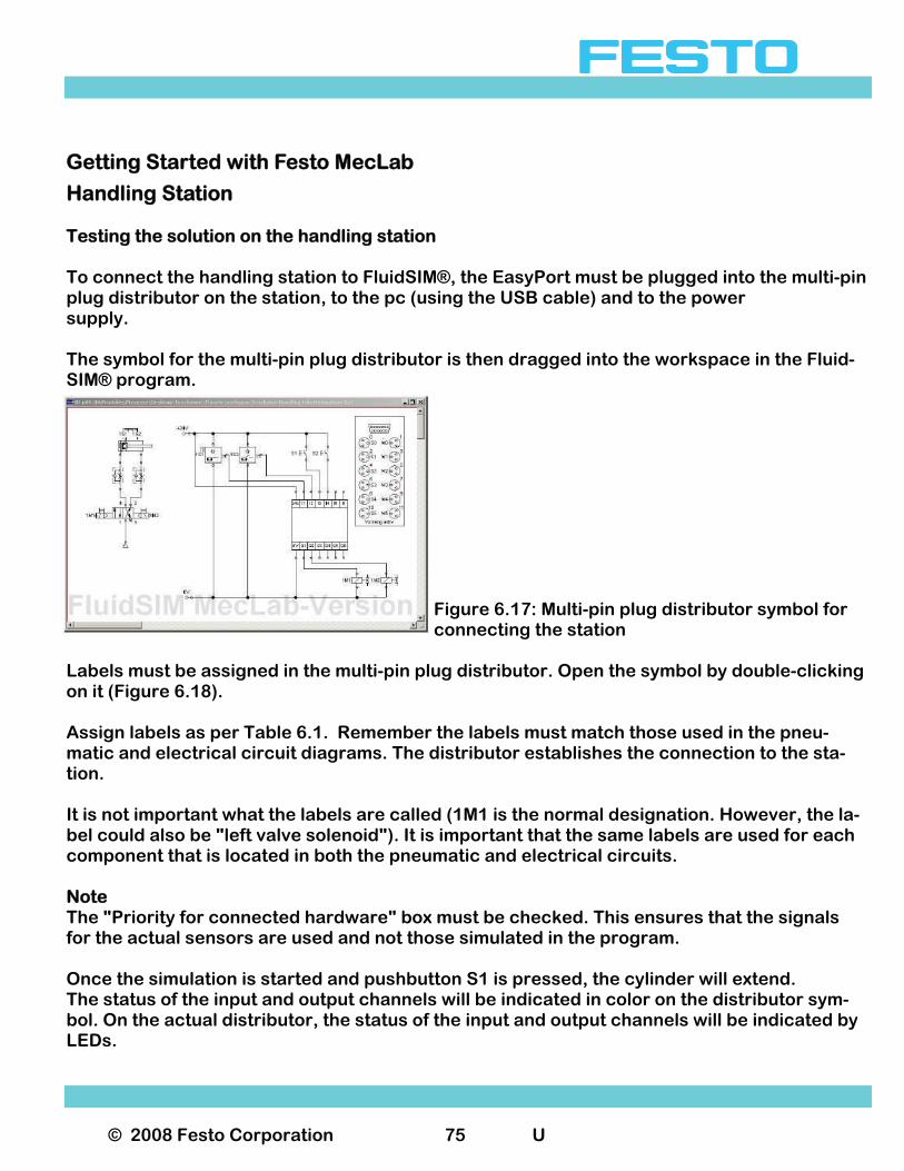
Handling Station Testing the solution on the handling station To connect the handling station to FluidSIM®, the EasyPort must be plugged into the multi-pin plug distributor on the station, to the pc (using the USB cable) and to the power supply. The symbol for the multi-pin plug distributor is then dragged into the workspace in the Fluid-SIM® program.
Figure 6.17: Multi-pin plug distributor symbol for connecting the station
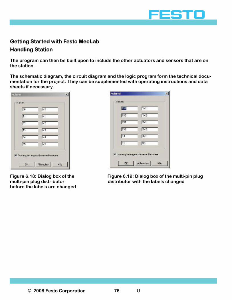
Labels must be assigned in the multi-pin plug distributor. Open the symbol by double-clicking on it (Figure 6.18). Assign labels as per Table 6.1. Remember the labels must match those used in the pneu-matic and electrical circuit diagrams. The distributor establishes the connection to the sta-tion. It is not important what the labels are called (1M1 is the normal designation. However, the la-bel could also be "left valve solenoid"). It is important that the same labels are used for each component that is located in both the pneumatic and electrical circuits. Note The "Priority for connected hardware" box must be checked. This ensures that the signals for the actual sensors are used and not those simulated in the program. Once the simulation is started and pushbutton S1 is pressed, the cylinder will extend. The status of the input and output channels will be indicated in color on the distributor sym-bol. On the actual distributor, the status of the input and output channels will be indicated by LEDs.
© 2008 Festo Corporation 76 U
Getting Started with Festo MecLab
Handling Station The program can then be built upon to include the other actuators and sensors that are on the station. The schematic diagram, the circuit diagram and the logic program form the technical docu-mentation for the project. They can be supplemented with operating instructions and data sheets if necessary.
Figure 6.18: Dialog box of the Figure 6.19: Dialog box of the multi-pin plug multi-pin plug distributor distributor with the labels changed before the labels are changed

© 2008 Festo Corporation 77 U
Getting Started with Festo MecLab
Lesson Planning Overview of the supplied media The MecLab® learning system consists of three components: 1. Hardware, 2. FluidSIM® programming and simulation software, Learning materials. The learning materials consist of the following: Fundamentals of Automation Technology (Theory section) The theory section covers the fundamentals of automation technology and mechatronics. It contains information on sensors, pneumatic and electric drives, relay controllers and pro-grammable logic controllers. It also includes a section on the history of automation technol-ogy and on how engineers work. This document is stored as a pdf file. You may print and distribute it to the students. You may not modify the content. Teaching with Meclab (Commissioning instructions) (this manual) The commissioning instructions consist of an introduction and detailed step-by-step instruc-tions on how to assemble and commission the three MecLab® stations. We recommend that you follow the instructions contained in this document. This document is stored as a pdf file. You may print and distribute it to the students. You may not modify the content.
© 2008 Festo Corporation 78 U
Getting Started with Festo MecLab
Lesson Planning Set of Exercises Each station has a set of exercises that begin as simple tasks. Each subsequent task (or exer-cise) builds on the previous and is a little more difficult. It starts out by learning about compo-nents, their function and symbols and ends with complex programming. The exercise workbooks are to be used by the students as worksheets. The worksheets are available as Word files. You may copy, distribute and modify these as needed. Presentation This contains the illustrations from the theory section and can be used during a lecture or to create your own documents. Hardware The hardware consists of the three stations, the EasyPorts, the necessary cables, work pieces and tools. Some of the exercises call for the conversion of the stations. For example changing, adjust-ing or relocating sensors, attaching or removing actuators. The system was designed so that components can be swapped between stations. For exam-ple: Sensors from the conveyor station can be used in the stack magazine or handling station. The stamping unit from the stack magazine station can be attached to the conveyor. It is also possible to form an assembly line with all three stations, however this calls for more advanced conversion and/or relocation and adjustment of the components. FluidSIM® Programming and Simulation Software The FluidSIM® programming and simulation software on the supplied CD-ROM is tailored to the functions of MecLab®. The software is easily installed on the PC from the CD-ROM.

© 2008 Festo Corporation 79 U
Getting Started with Festo MecLab
Lesson Planning Lesson Design MecLab® should be used to teach programming as well as mechanical makeup, setup and conversion of automated systems. Lessons can be divided into three phases: 1. Preparation 2. Project 3. Follow-up and Assessment. Preparation Normally, students do not have access to industrial production and therefore no relationship with the topic. If at all possible it is advised that the students are taken on a field trip to see an automated production facility before starting to work with MecLab®. The emphasis of the visit should be to recognize that an automated assembly system always includes functions for: 1. Conveying 2. Handling 3. Storing and feeding work pieces Preparation Normally, students do not have access to industrial production and therefore no relationship with the topic. If at all possible it is advised that the students are taken on a field trip to see an automated production facility before starting to work with MecLab®. The emphasis of the visit should be to recognize that an automated assembly system always includes functions for: 1. Conveying 2. Handling Storing and feeding work pieces These, of course, are the basic functions of the MecLab®.
© 2008 Festo Corporation 80 U
Getting Started with Festo MecLab
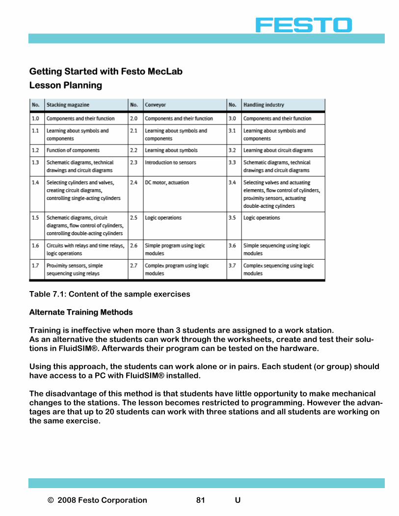
Lesson Planning If a visit to an actual production facility is not possible, the videos supplied on the CD-ROM can be used. In the follow-up phase, the results should be summarized and a connection should be made with the learning system: Which functions are found in the stations in our classroom? Which components were also present in the actual production facility? Group work MecLab® is designed for project-based teaching in small groups. The recommended group size is 2 students for each station (they will also need a PC with the supplied FluidSIM® soft-ware). Before starting the group work, it is a good idea to give a general introduction on using Fluid-SIM®, connecting the stations to the PC and also the function of the components. Students must also be made familiar with the safety information. Project work can be introduced with an explanation about certain topics, for example sen-sors, pneumatics, circuit or programming technology. Instructor resources include the infor-mation in the theory section, the supplied PowerPoint presentation and the animations on CD-ROM and in FluidSIM® . The Instructor can allow the students to acquire the information they need to complete the exercises on their own (within the window of the project work). In this case, it is useful to al-low the students to present their results once the exercises have been completed. This is im-portant given the fact that the subject matter is similar, but not completely identical between the three stations. The presentations will help to ensure that all students have the same level of knowledge. The exercises become increasingly challenging. Table 7.1 provides an overview of the objec-tives of the exercises. The stack magazine station has the easier exercises and the handling station has the more complex exercises. That leaves the exercises for the conveyor station somewhere in the middle. The time required to complete each exercise varies from 1 to 4 lessons depending on the level of difficulty, school type, age group or preparation.
© 2008 Festo Corporation 81 U
Getting Started with Festo MecLab
Lesson Planning
Table 7.1: Content of the sample exercises Alternate Training Methods Training is ineffective when more than 3 students are assigned to a work station. As an alternative the students can work through the worksheets, create and test their solu-tions in FluidSIM®. Afterwards their program can be tested on the hardware. Using this approach, the students can work alone or in pairs. Each student (or group) should have access to a PC with FluidSIM® installed. The disadvantage of this method is that students have little opportunity to make mechanical changes to the stations. The lesson becomes restricted to programming. However the advan-tages are that up to 20 students can work with three stations and all students are working on the same exercise.
© 2008 Festo Corporation 82 U
Getting Started with Festo MecLab
Lesson Planning Follow-up and assessment Upon completion of each project exercise the students should be encouraged to reflect on what they have accomplished. As part of this process students should conduct a presenta-tion on what they have learned about the operation of the stations, the sensors, actuators and control algorithms used in the stations. They should be able to provide an overview of the stations. By doing this students should will understand that automated systems always in-volve the interaction of sensors, actuators and controllers. Future Projects The exercises are intended to introduce the topic of automation. They help show how the sta-tions are programmed and how they operate. The problem definition in each exercise is written as though a “customer” is specifying what they want from a machine builder. The learning experience can be made more realistic if the teacher assumes the role of the "customer" and “hires” a group of students (who play the role of “machine builder”) to supply a station (or a "production line") with a specific or de-fined function. The students then need to plan, execute and document (e.g. including operat-ing instructions) the project and “deliver” the "product" to the customer. The “delivery” of the product can also include a formal presentation. There is no sample solution for these problem definitions. This is intentional. Normally there are several options for fulfilling a technical task. They should be assessed using the following criteria: 1. Function. Did the project meet the specified function? 2. Economy. How much did it cost? 3. Deadline. Was the project completed on schedule? 4. Documentation. Were circuit diagrams, schematic diagrams, parts lists, programs, oper
ating instructions provided? 5. Project management. How well did the students work together? Did each student perform
in the group? We have include a partial listing of project ideas, exercises, and suggestions for the technical solutions. These project ideas fall into one of two categories: expanding the Functions of individual stations and linking several stations to form a production line.
© 2008 Festo Corporation 83 U
Getting Started with Festo MecLab
Lesson Planning Changing or modifying the stations This is done by either adding components or by modifying programs. For example: • Empty magazine warning on the stack magazine station.
− Use a through-beam sensor to monitor parts in the magazine.
• Continuously pushing out new work pieces until the magazine is empty.
− Fill level monitoring using a through-beam sensor
• Warning of incorrectly inserted parts in the stack magazine station.
− Monitor using an inductive sensor (only for metal work pieces).
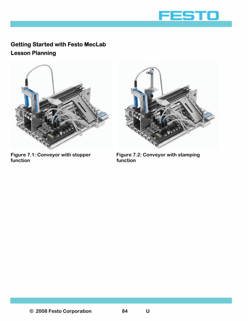
• Conveyor with buffer function (stopping a part for x seconds).
− Attachment of the deflector to the opposite side of the conveyor.
• Extending the conveyor to include a stamping function.
− Attach the stamping unit to the conveyor.
• Y-axis of the handling station stops half way through its stroke.
− Take the proximity sensor from the stack magazine and position it on the mid point of the handling station’s “Y” axis. Use a 3/2-way directional control valve.
Remember that when making these “conversions” an appropriate program must be created for each solution.
© 2008 Festo Corporation 84 U
Getting Started with Festo MecLab
Lesson Planning
Figure 7.1: Conveyor with stopper Figure 7.2: Conveyor with stamping function function
© 2008 Festo Corporation 85 U
Getting Started with Festo MecLab
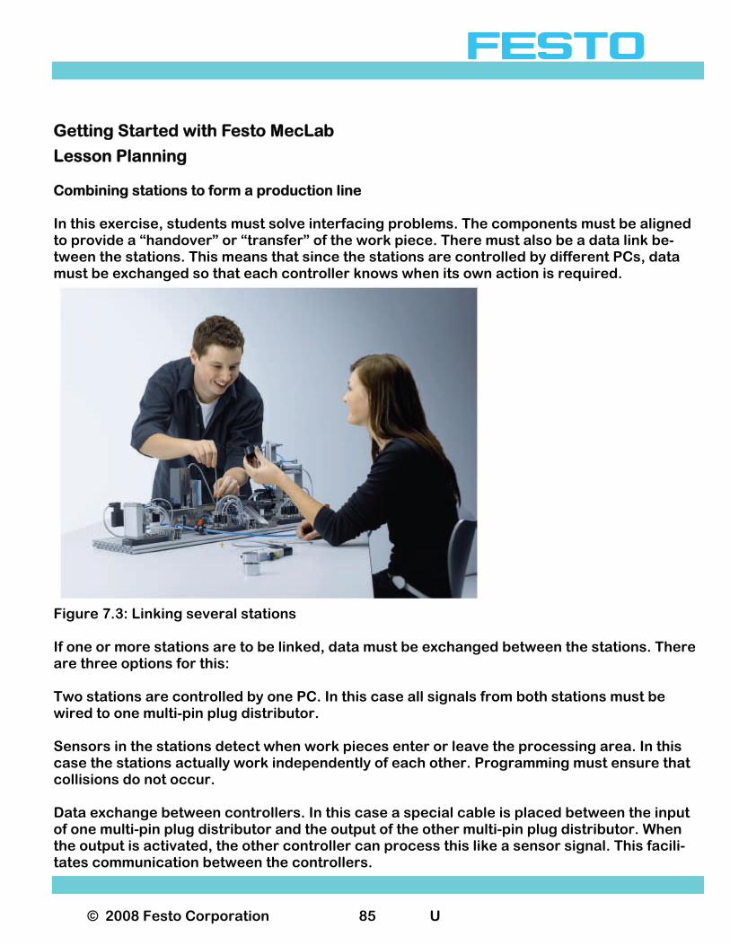
Lesson Planning Combining stations to form a production line In this exercise, students must solve interfacing problems. The components must be aligned to provide a “handover” or “transfer” of the work piece. There must also be a data link be-tween the stations. This means that since the stations are controlled by different PCs, data must be exchanged so that each controller knows when its own action is required.
Figure 7.3: Linking several stations If one or more stations are to be linked, data must be exchanged between the stations. There are three options for this: Two stations are controlled by one PC. In this case all signals from both stations must be wired to one multi-pin plug distributor. Sensors in the stations detect when work pieces enter or leave the processing area. In this case the stations actually work independently of each other. Programming must ensure that collisions do not occur. Data exchange between controllers. In this case a special cable is placed between the input of one multi-pin plug distributor and the output of the other multi-pin plug distributor. When the output is activated, the other controller can process this like a sensor signal. This facili-tates communication between the controllers.
© 2008 Festo Corporation 86 U
Getting Started with Festo MecLab
Projects Objectives of the Project Lesson For students the project itself is the goal towards which all actions are directed. For the teacher, it is a way of encouraging students to work on their own (e.g. planning, executing and evaluating). The project lesson is a type of activity-oriented lesson. It offers the opportunity to go beyond the technical level and to encourage active and constructive thought processes. The project lesson is thus a comprehensive means of developing competencies. The exercises and problem definitions for the project lesson should be comprehensive and realistic. It should include a deadline as well as scheduled “milestones”. 8.2 Characteristics of the Project Lesson Project work as an open lesson form requires the teacher to plan the sequential structure of the project, the students' capabilities and the conditions under which the project is to be car-ried out. A lesson can be described as open if the subject matter as well as the manner in which it is learned is not prescribed and students can follow different solution processes that they have defined. The term "project lesson" is often used loosely. There are characteristics that define and de-scribe this method. The project lesson should include some of the following: Practice-oriented Students should recognize the importance of theory and practice. They can either gain this at the start of the project work or experience it while working on the project. Interdisciplinary The nature of the project lesson requires the inclusion of several scientific disciplines or fields (science, technology engineering and math). Engineering sciences are multi-dimensional and tend to focus on creative problem solving. They start with a “needs-analysis” and aim towards what is physically and economically possible, ecologically sustain-able and humanly desirable. In other words, work on technical projects is driven by human need and technical action, both of which may have conflicting objectives.
© 2008 Festo Corporation 87 U
Getting Started with Festo MecLab
Projects Encourages Self-organization, personal responsibility and planning Students should work on their own as much as possible during the project lesson. This will enable them to plan, execute and evaluate their work. The teacher acts as a moderator, ob-server and, when needed, an advisor. Encourages different social and organizational forms The project lesson encourages team work, group-planned individual work and individual work. The teacher can guide students towards a particular form of work or allow the struc-ture to develop spontaneously. Project work can be organized in different ways depending on the subject matter. The following four versions have proven to be effective: 1. Parallel work by a number of teams working on the same project. 2. All teams are subject to the same conditions. The different project solutions are assessed
at the project deadline. 3. Separate/joint team work on the same project 4. The groups work separately on the same project in the initial phase. Each group presents
its results. The decision about which proposed solution to use is made jointly. The project is concluded jointly.
Joint-separate-joint work on the same project. Students discuss the subject matter of the project and the different ways of working on it. The overall project is broken down into subtasks. Problems are identified and the teams de-cide which problems to solve. Each team presents its solution to the class. Following a “peer review” round, the project is concluded.
© 2008 Festo Corporation 88 U
Getting Started with Festo MecLab
Projects Problem Solving Processes An important characteristic of the project lesson is the process by which the problem is solved. In order to meet the objective the student moves from task preparation to problem solving relying on previously learned knowledge and expertise while also gaining new skills and abilities. Purpose and Goal-Oriented In engineering, all activities are performed with a specific goal in mind. For the students, the subject matter of the project (e.g. a controller for automating a process) is the goal. If they recognize that new technical knowledge is required to reach this goal, they are must be moti-vated to obtain the needed skills and abilities on their own, because they recognize their im-portance in achieving the goal. The subject matter of the project is not as important for the Teacher. Rather it is a means to an end, a medium to be learned in order to achieve the educational objectives. Ultimately however, the aim is to develop students' competence and help prepare them for a rewarding career. Project Lesson Phases In order to successfully complete a project on their own, students need a certain amount of technical knowledge. They should be methodical in their approach and have some experi-ence in solving problems. This means that they: Are familiar with problem solving strategies, from identifying the problem to evaluating the
solution. Have basic problem solving skills. Have developed self-confidence in dealing with problems. Have the readiness, willingness and persistence to grapple with problems even when con-
fronted with obstacles.
© 2008 Festo Corporation 89 U
Getting Started with Festo MecLab
Projects Deciphering and Understanding the Problem (preparatory phase) This preparatory or informational phase deals with problem definition. In other words stu-dents consider the project goals and establish the steps or tasks. The project goal must be defined. If it is the students' first project lesson, the teacher must inform them of the purpose of project work and how it is carried out. The preparatory phase should be kept as short as possible so as not to deflate the students' motivation. Identifying Possible Solutions (evaluation phase) In the evaluation phase, the students must identify solutions to reach the goal and compare them against each other. The solutions must also be compared with the material conditions and the students' capabilities. The chosen solution should represent a compromise between what is technically intended, economically prudent and what the material conditions and hu-man resources can support. Planning a Solution (planning phase) The students' task in the planning phase is to plan and organize the steps required to reach the goal. This includes material planning (tools and materials) and human resources consid-erations (number of groups, size and composition of the groups). Secondary goals and sub-groups are formed. Project Milestones (interaction phase) During the interaction phase, the students work on solving the project secondary goals in their respective subgroups. The teacher's main role in this phase is to ensure that all neces-sary information is available. All results should be documented by each group and prepared for the presentation.
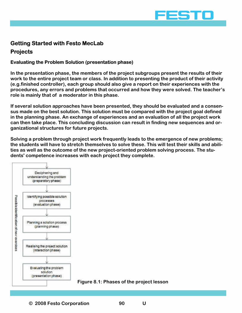
© 2008 Festo Corporation 90 U
Getting Started with Festo MecLab
Projects Evaluating the Problem Solution (presentation phase) In the presentation phase, the members of the project subgroups present the results of their work to the entire project team or class. In addition to presenting the product of their activity (e.g.finished controller), each group should also give a report on their experiences with the procedures, any errors and problems that occurred and how they were solved. The teacher’s role is mainly that of a moderator in this phase. If several solution approaches have been presented, they should be evaluated and a consen-sus made on the best solution. This solution must be compared with the project goal defined in the planning phase. An exchange of experiences and an evaluation of all the project work can then take place. This concluding discussion can result in finding new sequences and or-ganizational structures for future projects. Solving a problem through project work frequently leads to the emergence of new problems; the students will have to stretch themselves to solve these. This will test their skills and abili-ties as well as the outcome of the new project-oriented problem solving process. The stu-dents' competence increases with each project they complete.
Figure 8.1: Phases of the project lesson