Embed Size (px)
Citation preview
DMA-C64-157/N
SET 2014
Emissão: EDP Distribuição – Energia, S.A. DTI – Direção de Tecnologia e Inovação
R. Camilo Castelo Branco, 43 – 1º 1050-044 Lisboa Tel.: 210021500 Fax: 210021444 E-mail: [email protected]
MATERIAIS PARA REDES – APARELHAGEM AT E MT
Órgão de Corte de Rede Tipo 3 (OCR3)
Características e ensaios
Elaboração: DTI, DAT Homologação: conforme despacho do CA de 2014-07-30
Edição: 1ª
DMA-C64-157/N
SET 2014
DTI – Direção de Tecnologia e Inovação Pág. 2/40
TABLE OF CONTENTS
1 INTRODUCTION .............................................................................................................................................. 5
1.1 Relevant changes in relation to the previous edition of this specification ................................................... 5
2 STANDARDS, MODULARITY, QUALITY AND TESTING ........................................................................................ 5
2.1 General ...................................................................................................................................................... 5
2.2 Modularity ................................................................................................................................................. 5
2.3 Quality ....................................................................................................................................................... 6
2.4 Environmental conditions .......................................................................................................................... 6
2.5 Testing ....................................................................................................................................................... 6
3 MODULE SPECIFICATION ................................................................................................................................. 6
3.1 Recloser ..................................................................................................................................................... 6
3.1.1 Type ...................................................................................................................................................... 6
3.1.2 International Standards......................................................................................................................... 6
3.1.3 Electrical Ratings ................................................................................................................................... 7
3.1.4 Current Sensing..................................................................................................................................... 8
3.1.5 Voltage Sensing..................................................................................................................................... 8
3.1.6 Mechanical Requirements ..................................................................................................................... 8
3.1.7 Functional requirements ....................................................................................................................... 9
3.1.8 Nameplate ............................................................................................................................................ 9
3.1.9 Environmental Requirements ................................................................................................................ 9
3.1.10 Tests ..................................................................................................................................................... 9 3.1.10.1 Generalities ........................................................................................................................................ 9 3.1.10.2 Type tests ........................................................................................................................................... 9 3.1.10.3 Routine tests ...................................................................................................................................... 9
3.2 Recloser Interface Module (RIM).............................................................................................................. 10
3.2.1 Functional Requirements .................................................................................................................... 10
3.2.2 Construction ....................................................................................................................................... 10
3.2.3 Technical requirements ....................................................................................................................... 10
3.3 Control Cabinet (CC) ................................................................................................................................ 10
3.3.1 International Standards....................................................................................................................... 10
3.3.2 General ............................................................................................................................................... 11
3.3.3 Environmental Requirements .............................................................................................................. 11
3.3.4 Other technical requirements ............................................................................................................. 11 3.3.4.1 Transport, storage, installation, operation and maintenance ............................................................ 11 3.3.4.2 Nameplate ....................................................................................................................................... 11
3.3.5 Type tests ........................................................................................................................................... 12
3.3.6 Routine tests ....................................................................................................................................... 12
3.4 Power Supply Module (PSM) .................................................................................................................... 12
3.4.1 General Requirements ........................................................................................................................ 12
DMA-C64-157/N
SET 2014
DTI – Direção de Tecnologia e Inovação Pág. 3/40
3.4.2 Functional Requirements .................................................................................................................... 12 3.4.2.1 Nameplate ....................................................................................................................................... 13
3.4.3 Environmental Requirements .............................................................................................................. 13
3.4.4 Type tests ........................................................................................................................................... 13
3.5 Remote Terminal Unit (RTU) .................................................................................................................... 13
3.5.1 International Standards....................................................................................................................... 13
3.5.2 General ............................................................................................................................................... 14
3.5.3 Inputs and outputs .............................................................................................................................. 14
3.5.4 Communication .................................................................................................................................. 15
3.5.5 Events and Time Tagging ..................................................................................................................... 15
3.5.6 Engineering ......................................................................................................................................... 15
3.5.7 Power Supply ...................................................................................................................................... 15
3.5.8 Front Operating Module (FOM) ........................................................................................................... 15
3.5.9 Environmental Requirements .............................................................................................................. 16
3.5.10 Type Tests ........................................................................................................................................... 16
3.6 Communication Interface Module (CIM) .................................................................................................. 16
3.6.1 International Standards....................................................................................................................... 16
3.6.2 General Requirements ........................................................................................................................ 16
3.6.3 Networking requirements ................................................................................................................... 16 3.6.3.1 Protocols .......................................................................................................................................... 16 3.6.3.2 Configuration requirements ............................................................................................................. 17 3.6.3.3 Router/Firewall requirements .......................................................................................................... 17 3.6.3.4 Security requirements ...................................................................................................................... 17 3.6.3.5 RF requirements ............................................................................................................................... 17
3.6.4 Environmental Requirements .............................................................................................................. 17
3.6.5 Power Supply ...................................................................................................................................... 17
3.6.6 Type Test ............................................................................................................................................ 17
3.7 Protection Module (PM) .......................................................................................................................... 17
3.7.1 International Standards....................................................................................................................... 17
3.7.2 General Requirements ........................................................................................................................ 18
3.7.3 Functional Requirements .................................................................................................................... 18
3.7.4 Environmental Requirements .............................................................................................................. 20
3.7.5 Power Supply ...................................................................................................................................... 20
3.7.6 Type Tests ........................................................................................................................................... 20
4 SOFTWARE FUNCTIONAL REQUIREMENTS .................................................................................................... 20
4.1 General .................................................................................................................................................... 20
4.2 Functionality ............................................................................................................................................ 20
4.2.1 Recloser mode .................................................................................................................................... 21
4.2.2 Sectionalizer mode.............................................................................................................................. 22
4.2.3 ABR - Automatic Backfeed Restoration ................................................................................................ 23
4.2.4 Power flow direction feature .............................................................................................................. 24
5 MISCELLANEOUS REQUIREMENTS ................................................................................................................. 24
DMA-C64-157/N
SET 2014
DTI – Direção de Tecnologia e Inovação Pág. 4/40
5.1 Languages ................................................................................................................................................ 24
6 Table of compliance ...................................................................................................................................... 24
DMA-C64-157/N
SET 2014
DTI – Direção de Tecnologia e Inovação Pág. 5/40
1 INTRODUCTION
This document specifies a recloser according to the IEC 62271-111 standard and a control cabinet to be used in EDP’s overhead Medium Voltage (MV) networks. The device shall be remotely controlled via the GSM network, using IEC 60870-5-104 as communication protocol, applying in particular the EDP Light Profile.
The recloser will also operate as a sectionalizer, with an automation function, as described later in this document.
In this document, this device is named as OCR3.
1.1 Relevant changes in relation to the previous edition of this specification
The most relevant changes are the following:
— If the sectionalizer functionality is not implemented, the equipment can be accepted although penalties will be applicable.
— Fault location functionality is optional and scored.
— SF6 can be accepted as insulating medium, although penalties will be applicable for equipment with this type of insulation.
— The battery shall be of sealed type with a lifetime of at least 4 years.
— Rogowski coil technology is not mandatory for current sensing.
— VPN requirements associated to the CIM are not mandatory.
— The Sensitive Ground/Earth Fault functionality is not mandatory.
— Ethernet connection between the RTU and the CIM is not mandatory.
— The recloser clearing time shall be less than 100 ms.
2 STANDARDS, MODULARITY, QUALITY AND TESTING
2.1 General
All reclosers covered by this specification shall be manufactured and tested in accordance with IEC 62271-111 or IEEE C37.60.
The recloser and controls shall be designed according to internationally recognized engineering practices, providing safety and reliability for operators and maintenance staff.
2.2 Modularity
The design of the recloser and control cabinet shall consist of modular construction to provide maximum flexibility.
A standard package configuration shall include the recloser, a Recloser Interface Module (RIM), a Control Cabinet (CC), a Remote Terminal Unit (RTU), a Power Supply Module (PSM), a Communication Interface Module (CIM) a Protection Module (PM) as well as a Front Operating Module (FOM) shall be provided. The overall package is referred to as “OCR3”.
The various mounting provisions for the recloser and control cabinet shall be included in the supply, taking in account the pole characteristics in the EDP network.
The hardware inside the control cabinet can be either individual modules or a combination of multifunctional modules, which combines the functionality of more than one module.
DMA-C64-157/N
SET 2014
DTI – Direção de Tecnologia e Inovação Pág. 6/40
If modules are combined it means that the requirements of the individual portion will apply to the combined module as well.
2.3 Quality
The manufacturer shall be independently certified to meet ISO 9001 Standards.
2.4 Environmental conditions
The operating temperature range for the OCR 3 shall be -20 °C to +40 °C with a relative humidity of 5 % to 95 % (non-condensing).
The OCR 3 shall work as per specification for an altitude up to 1000 m above sea level.
Precipitation and condensation must be considered and a level of solar radiation not below the 1000 W/m2.
2.5 Testing
Each module shall be tested according to the requirements shown in the relevant chapter of this specification. The manufacturer shall demonstrate compliance with the specification requirements by presenting test reports elaborated by accredited laboratories, or others accepted by EDP.
Nevertheless, there are a number of type tests related to environmental performance that must be carried out on the complete OCR3, i.e. with all modules assembled together. These will be carried out according to the standards given in Table 1:
Table 1
International standards
Reference Title
IEC 60068-2-1 Environmental testing - Part 2-1: Tests - Test A: Cold
IEC 60068-2-2 Environmental testing - Part 2: Tests. Tests B: Dry heat
IEC 60068-2-30 Environmental testing - Part 2-30: Tests - Test Db: Damp heat, cyclic (12 h + 12 h cycle)"
3 MODULE SPECIFICATION
3.1 Recloser
3.1.1 Type
This section describes the requirements for a three phase automatic circuit recloser, which is to be used in the overhead medium voltage network of EDP.
The recloser shall be maintenance free.
3.1.2 International Standards
The recloser covered by this specification shall be manufactured and tested in accordance with all relevant IEC 62271-111, IEEE and IEC and EN Standards as shown in Table 2.
DMA-C64-157/N
SET 2014
DTI – Direção de Tecnologia e Inovação Pág. 7/40
Table 2
International standards
Reference Title
IEC 62271-111 IEEE C37.60
High voltage switchgear and control gear - Part 111: Overhead, pad-mounted, dry vault, and submersible automatic circuit reclosers and fault interrupters for alternating current systems up to 38 kV
IEEE C.37.100 IEEE Standard Definitions for Power Switchgear
EN 50160 Voltage characteristics of electricity supplied by public distribution systems
IEC 61000-4 Electromagnetic Compatibility - Testing and Measurement Techniques
IEC 60529 Degrees of protection provided by enclosures (IP Code)
EN 50102 Degrees of protection provided by enclosures for electrical equipment against external mechanical impacts (IK Code)
IEC 60815 Guide for the Selection of Insulators in Respect of Polluted Conditions
IEC 60068-2-5 Environmental testing - Part 2-5: Tests - Test Sa: Simulated solar radiation at ground level and guidance for solar radiation testing
IEC 61869-1 Instrument transformers - Part 1: General requirements
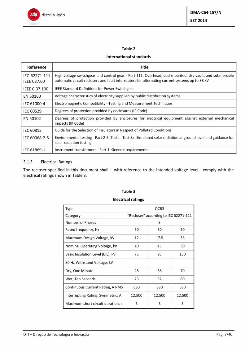
3.1.3 Electrical Ratings
The recloser specified in this document shall – with reference to the intended voltage level - comply with the electrical ratings shown in Table 3.
Table 3
Electrical ratings
Type OCR3
Category “Recloser” according to IEC 62271-111
Number of Phases 3
Rated frequency, Hz 50 50 50
Maximum Design Voltage, kV 12 17.5 36
Nominal Operating Voltage, kV 10 15 30
Basic Insulation Level (BIL), kV 75 95 150
50 Hz Withstand Voltage, kV
Dry, One Minute 28 38 70
Wet, Ten Seconds 23 32 60
Continuous Current Rating, A RMS 630 630 630
Interrupting Rating, Symmetric, A 12.500 12.500 12.500
Maximum short circuit duration, s 3 3 3
DMA-C64-157/N
SET 2014
DTI – Direção de Tecnologia e Inovação Pág. 8/40
3.1.4 Current Sensing
The recloser shall be equipped with 3 current sensors, suitable for operation in a medium voltage distribution network and considering the ratings show in Table 3.
The current sensor shall be housed within the encapsulation of the recloser. The current sensors shall be according to IEC 61869-1 and other applicable relevant standards.
The manufacturer shall clearly indicate the measurement range of its current sensors and demonstrate their precision according to the relevant IEC standards.
The accuracy of the current measurements shall be high enough to respect the complete measurement chain accuracy indicated in 3.5.3 .
In case CTs are used, the system must be designed in a way that disconnecting the cable in any end, shall automatically lead to the short circuit of CT’s secondary side.
3.1.5 Voltage Sensing
The recloser shall be equipped with 6 sensors, 3 on each side of the equipment.
The voltage sensor shall be housed within the encapsulation of the recloser. The voltage sensors shall be according to IEC 61869-1 and other applicable relevant standards.
By explicit agreement between EDP and the manufacturer, it can be accepted less than 3 sensors on one of the sides of the recloser, or other type of sensors, even not encapsulated, as long as the manufacturer demonstrates the proper functioning of the solution and there are voltage detection functionalities for the 3 phases on that side, with a user programmable threshold. This threshold shall vary, at least, between 95 % and 20 % of the nominal line voltage. The maximum step for user configuration of the voltage detection threshold shall be 5 %.
The manufacturer shall clearly indicate the measurement range of its voltage sensors and demonstrate they are according to the relevant IEC standards, namely during the FAT (Factory Acceptance Tests).
The accuracy of the voltage measurements shall be high enough to respect the complete measurement chain accuracy indicated in 3.5.3 .
3.1.6 Mechanical Requirements
The recloser shall be designed for 10.000 complete open/close operations.
All three poles of the recloser will be operated simultaneously.
The recloser shall use solid polymer insulation and provide complete encapsulation of the internal vacuum interrupters. The insulation shall be highly resistant to ozone, oxygen, moisture, contamination, ultraviolet light and voltage tracking. No coatings are acceptable.
Alternatively, SF6 gas can be accepted as insulation medium. The encapsulation shall be a closed or sealed pressure system, according to IEC 62271-111. The encapsulation shall also be tested according to the IEC 62271-111.
SF6 gas is not acceptable for an interrupting medium. Current interruption shall occur in vacuum interrupters.
A single break on each phase is accomplished by separating contacts inside the vacuum interrupter.
The interruption mechanism shall be operated by a magnetic actuator, providing linear trip-and-close motion to three encapsulated vacuum interrupter modules.
Mounting support brackets shall be provided for pole mounting.
The mounting provisions for all mounting types and all available pole types including the support for the six surge arresters (3 on each side) and Supply VT shall be part of the delivery.
DMA-C64-157/N
SET 2014
DTI – Direção de Tecnologia e Inovação Pág. 9/40
3.1.7 Functional requirements
The recloser shall be mechanically and electrically trip free. Any applied close signal, shall not inhibit the recloser from tripping on the programmed time-current curve.
The mechanism shall perform consistently, regarding opening and closing times, for 20 m control cables. Nevertheless, when specifically requested, it may be longer and the mechanism shall perform similarly.
The mechanism shall include an operating handle to manually trip by means of a hot stick. Lockout is ensured either mechanically or electrically via operation on the FOM. Lockout means that no closing will be possible, either locally or remotely.
A contact position indicator shall be mounted on the bottom of the recloser for access viewing from the ground.
The recloser shall have a ground connector mounted to the recloser housing.
The recloser clearing time, as defined per IEC 62271-111, shall be less than 100 ms (with relay “protection operating time” set to 0 ms/instantaneous) in any operational situation (under load or short-circuits), under all specified environmental conditions. The closing time shall be less than 100 ms, as defined per IEC 62271-111 in any operational situation and under all environmental conditions. The supplier shall demonstrate the required performance via test reports.
The magnetic actuator shall be powered by either batteries or capacitors.
3.1.8 Nameplate
Each recloser shall possess a metal name/type label placed in a visible position. The nameplate must be suitable for outdoor application. It should contain the information according to IEC 62271-111.
3.1.9 Environmental Requirements
The requirements described in section 2.4 apply.
The recloser must be able to be installed in air atmospheres considered polluted with a degree of pollution of level Heavy, in accordance with IEC 60815-1 Standard.
3.1.10 Tests
3.1.10.1 Generalities
The conformity of the characteristics of the recloser with the present specification must be confirmed through the execution of tests, performed in accredited laboratories or others with the previous agreement of EDP.
3.1.10.2 Type tests
The type tests must be executed on a representative recloser prior to delivery, with the aim to show that all reclosers will comply with the specified requirements.
A recloser is considered as representative when it will have the same nominal voltage, the same nominal current, the same type, the same dielectric and the same production system.
The type tests must be executed according to IEC 62271-111 Chapter 6. Moreover, the radiation performance of the recloser module shall be verified according to IEC 60068-2-5.
3.1.10.3 Routine tests
The manufacturer has to make sure that all reclosers delivered are tested and inspected before being shipped. The tests have to be conducted and documented on each individual recloser.
The factory tests on the recloser must at least include all tests as per IEC 62271-111, Chapter 7.
DMA-C64-157/N
SET 2014
DTI – Direção de Tecnologia e Inovação Pág. 10/40
In case there are any controls in the recloser, the respective standard tests from the RTU section have to be applied as well.
3.2 Recloser Interface Module (RIM)
3.2.1 Functional Requirements
The recloser shall be connected to the control cabinet using separable weatherproof connectors at the recloser and at the control cabinet.
The RIM control cable’s standard length shall be 20 m. Nevertheless, when specifically requested, it may be longer.
The RIM shall have a suitable size and number of cores for the connection of the Control Cabinet.
The wires transmitting the currents and voltages from current and voltage sensors, shall be suitably protected against external electric and magnetic fields. The wires are either embedded in the RIM or connected to the CC as a separate cable.
Disconnecting the RIM shall not lead to tripping of the recloser.
3.2.2 Construction
The RIM shall have adequate mechanical and UV protection.
3.2.3 Technical requirements
The voltage rating shall be 0.6/1 kV. The conductors shall be circular, shaped or compacted.
The maximum conductor temperature shall be 90 °C.
3.3 Control Cabinet (CC)
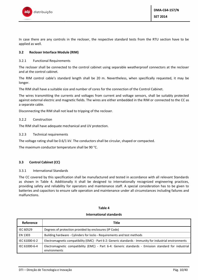
3.3.1 International Standards
The CC covered by this specification shall be manufactured and tested in accordance with all relevant Standards as shown in Table 4. Additionally it shall be designed to internationally recognized engineering practices, providing safety and reliability for operators and maintenance staff. A special consideration has to be given to batteries and capacitors to ensure safe operation and maintenance under all circumstances including failures and malfunctions.
Table 4
International standards
Reference Title
IEC 60529 Degrees of protection provided by enclosures (IP Code)
EN 1303 Building hardware - Cylinders for locks - Requirements and test methods
IEC 61000-6-2 Electromagnetic compatibility (EMC) - Part 6-2: Generic standards - Immunity for industrial environments
IEC 61000-6-4 Electromagnetic compatibility (EMC) - Part 6-4: Generic standards - Emission standard for industrial environments
DMA-C64-157/N
SET 2014
DTI – Direção de Tecnologia e Inovação Pág. 11/40
3.3.2 General
The controls for the recloser shall be contained in a weatherproof control cabinet (CC).
The cabinet shall be suitable for outdoor installation on the pole, at approximately 1,5 m above ground level, easy to reach for an operator.
The CC will house the PSM, RTU, FOM, CIM, and the PM.
It shall be designed to protect unqualified person from opening the CC or operating the recloser.
The CC shall have a weatherproof connector for the RIM and for eventual external power sources on the bottom of the CC to prevent water and dust to enter.
The CC shall be made of stainless steel or aluminum.
The CC shall have a lock for the cabinet door. The lock must close in two points (minimum) and must allow a key European type half cylinder with a total length of 40,5 mm, according to EN 1303, which will be supplied by EDP. The cam shall be positioned at 3 o’clock.
The CC shall have a 4 digit operating counter for the connected recloser.
The CC shall provide an AC socket with suitable voltage and power to feed a standard laptop PC and a field test device. The maximum output power should be at least 200 W. The output shall be overload protected in order to protect the voltage supply transformer from the overload.
The CC shall have internal light.
The CC shall have the circuit diagram attached inside the cabinet.
The CC shall provide lifting facilities.
All control cables shall be connected with a weatherproof fitting to prevent water from entering.
The CC, cable and the fitting shall be sufficiently protected against vandalism.
The CC shall contain all Input/Output terminal blocks for interfacing the various modules inside the CC.
The CC shall have means to prevent condensation, considering the specified environmental conditions.
No moving parts (e.g. fans, hard discs, etc.) are accepted in the CC and in all its components.
3.3.3 Environmental Requirements
The requirements described in section 2.4 apply.
The CC shall have a protection level at least equivalent IP 54.
3.3.4 Other technical requirements
3.3.4.1 Transport, storage, installation, operation and maintenance
The manufacturer shall supply the necessary instructions for the transport, storage, installation, operation and maintenance.
3.3.4.2 Nameplate
Each CC shall possess a name/type label of waterproof material, placed in a visible position. The nameplate must contain at least the following items:
— Type of the CC;
— Manufacturer’s name;
DMA-C64-157/N
SET 2014
DTI – Direção de Tecnologia e Inovação Pág. 12/40
— Manufacturer’s serial number;
— Year of production;
— Total mass (with all components included).
3.3.5 Type tests
The CC shall be type tested and certified according to the emission and immunity levels described in IEC 61000-6-2 and IEC 61000-6-4, including all the equipment installed.
The Ingress protection (IP) rating of the CC shall be tested and certified, according to IEC 60529 standard.
3.3.6 Routine tests
The manufacturer of the CC has to make sure that all CC delivered are tested and inspected before being shipped. The tests have to conducted and documented on each individual CC. The factory test shall at least include these functions:
— CC inspected for damage;
— CC inspected for proper assembly;
— work light checked for proper function;
— cables and conduit are routed properly;
— control cabinet door functions properly;
— warning labels are present, current and readable;
— data sheet is attached to the inside of the control cabinet door;
— operator's manual and documentation is present;
— control cabinet keys are present and functioning properly;
— power off/on test is acceptable.
All modules inside the CC have to be tested for functionality and interoperability. A full test plan has to be provided with the submission of the tender.
3.4 Power Supply Module (PSM)
3.4.1 General Requirements
The Power Supply Module (PSM) is supplying the devices in the control cabinet (CC) and the recloser with electrical energy.
3.4.2 Functional Requirements
The nominal input voltage range shall be between 100 and 240 VAC at 50 Hz and a tolerance of ±10 %.
The incoming power shall be protected and isolated by a circuit breaker.
The supply from the battery shall be protected and isolated by a circuit breaker or a fuse.
The state of all circuit breakers shall be individually indicated as a signal to the RTU. It shall be possible to transmit this information to the control center. Alternatively, it is acceptable to transmit to the control center the loss of AC supply and loss of battery.
A single phase voltage transformer for the power supply from the overhead line shall be included. The supplier must declare the characteristics of the VT and must test it according to the relevant IEC standards.
A battery shall be provided for backup control operation in the event of loss of primary supply.
DMA-C64-157/N
SET 2014
DTI – Direção de Tecnologia e Inovação Pág. 13/40
The battery shall be completely sealed.
The PSM shall provide the functionality of automatic and periodic battery testing with a state signalization to the RTU.
The PSM shall be able to detect a deteriorating state of a battery close to the end of its lifespan and shall signal it to the RTU.
The battery shall be designed for a lifetime of at least 4 years in all operating conditions.
The battery shall be capable of operating the recloser, the control, protection and communication for a minimum of 24 hours with no external supply connected and the cabinet door closed. During the 24 hours it shall be possible to have 6 open and closing actions (see section 3.4.4 ).
If the primary supply has not been restored within the allowable discharge time of the battery, based not only on the 24 hours but also on the battery capacity detection, the control shall automatically shut down.
The supplier shall indicate where to connect an auxiliary power supply in the case of a complete loss of energy.
3.4.2.1 Nameplate
Each PSM shall possess a name/type label of waterproof material, placed in a visible position. The nameplate must contain at least the following items:
— input Voltage and Frequency;
— output Voltage and Frequency;
— input power;
— output power.
3.4.3 Environmental Requirements
The requirements described in section 2.4 apply.
3.4.4 Type tests
The manufacturer shall present a certificate of a type test made according to an international standard to guarantee the 4 year lifetime of its batteries.
A special test for the battery concerning the ability to perform 6 open and closing actions during 24 hours shall be carried out in the following manner:
— 5 opening and closing actions to be made at any time during the 24 hours according to manufacturer's proposal;
— 1 opening and closing action to be made in the last 15 minutes before the end of the end of the 24 hour period.
3.5 Remote Terminal Unit (RTU)
3.5.1 International Standards
The RTU covered by this specification shall be manufactured and tested in accordance with all relevant IEC and EDP Standards as shown in Table 5.
DMA-C64-157/N
SET 2014
DTI – Direção de Tecnologia e Inovação Pág. 14/40
Table 5
International standards
Reference Title
IEC 62271-111 Overhead, Pad-Mounted, Dry Vault, and Submersible Automatic Circuit Reclosers and Fault Interrupters for Alternating Current Systems Up to 38 kV
IEC 60870-2-1 Telecontrol equipment and systems - Part 2: Operating conditions - Section 1: Power supply and electromagnetic compatibility
IEC 60870-2-2 Telecontrol equipment and systems - Part 2: Operating conditions - Section 2: Environmental conditions (climatic, mechanical and other non-electrical influences)
IEC 60870-5-104 Telecontrol equipment and systems – Part 5-104: Transmission protocols – Network access for IEC 60870-5-101 using standard transport profiles
DEF-C98-422 Instalações de Telecomunicações – Light Protocol Implementation Document (IEC60870-5-104)
3.5.2 General
The Remote Terminal Unit (RTU) shall be encased in control cabinet.
The RTU shall be designed to protect unqualified person from operating.
The RTU shall allow remote access.
The RTU shall provide a self-test and diagnosis function.
The RTU shall provide a watchdog function. In case of failure of any OCR 3 module, this should be signaled to the control center.
3.5.3 Inputs and outputs
The RTU shall have enough inputs to allow the following measurements:
— 6 voltage measurements (one per each phase on each side of the device) or the number the manufacturer supplies respecting the requirements of 3.1.5 ;
— 3 current measurements (one per each phase);
— Battery capacity measurement;
— SF6 pressure measurement (in case SF6 is used as insulation medium).
The SF6 pressure control (when applicable) can also be associated to a digital input, assuming the measurement is made in module distinct of the RTU.
The complete measurement chain (analogue measurement plus analogue-digital conversion) shall have accuracy not worse than ±5 %.
Additionally to voltage magnitude in each phase and currents in each phase, it shall be able to measure kW, kvar, kWh and kvarh. Alternatively it is accepted to be able to measure kW, kWh and PF.
The digital status inputs shall be provided with optical insulation.
The digital inputs and outputs shall be enough to control and monitor the following functionalities:
— Control (open/close) and monitor the status of the switch;
— Control (activate/deactivate) protection functions and monitor the tripping of phase and ground over-current functions;
— Control and monitor the operation mode of the OCR3 (recloser/sectionalizer);
— Control (activate/deactivate) auto reclosing and monitor the initiation of reclosing cycles;
DMA-C64-157/N
SET 2014
DTI – Direção de Tecnologia e Inovação Pág. 15/40
— Control (activate/deactivate) ABR (Automatic Backfeed Restoration) mode.
3.5.4 Communication
It shall support a communication protocol according to IEC 60870-5-104 in accordance with the PID called “Protocol Implementation Document (Light Version)” (DEF-C98-422) from EDP Distribuição. The certificate will be valid for a specific model of RTU and firmware version. Changes in the RTU model or firmware version will require a new certificate to be obtained.
A communication to the engineering PC shall be possible by means of an electric, optic or wireless interface.
The communication between the RTU and the network control center (NCC) is done through the Communication Interface Module (CIM) described in section 3.6 . The RTU/CIM set must contain a watchdog function to reconnect to the GPRS network in case the connection has been dropped by external influences (e.g. interference, occasional telecommunication system outages, etc.)
3.5.5 Events and Time Tagging
The RTU shall have event detection with a time resolution of 10 ms.
The RTU shall have an internal clock for time stamping in case there is no external timing, for example from the network control center (NCC).
The internal clock shall have a maximum deviation of 200 ms/h when not synchronized.
The RTU shall have an event buffer to store events.
The event buffer shall have a capacity of at least 100 events. An event can consist of:
— Protection functions pickup and trip;
— Alarms associated to malfunctions in the CC (fuses or circuit breaker tripping, malfunctions in the modules);
— Other alarms (open door, user configurable alarms).
The buffer shall keep the most recent events and delete the oldest ones, in a “first in – first out” manner.
3.5.6 Engineering
The configuration of the RTU shall also be carried out from a remote PC via Internet links or the customer's Intranet or by a download via the NCC by IEC 60870-5-104 file transfer protocol.
Upload of the data files shall be possible for reverse data engineering.
3.5.7 Power Supply
The RTU shall be fed by the battery backed PSM in the CC.
3.5.8 Front Operating Module (FOM)
The RTU shall be equipped with a FOM to allow operators to locally control the switch.
It shall be protected from any unauthorized operation.
Additionally it shall provide the operator with at least the following information:
— selector switch for LOCAL / REMOTE;
— indicator for LOCAL / REMOTE;
— push buttons for OPEN and CLOSE;
— switch position indication;
— selector switch for protection profile;
DMA-C64-157/N
SET 2014
DTI – Direção de Tecnologia e Inovação Pág. 16/40
— indicator for protection pickup and trip;
— nameplate.
3.5.9 Environmental Requirements
The requirements described in section 2.4 apply.
3.5.10 Type Tests
The type test must be executed on a representative RTU prior to delivery, with the aim to show that all RTU’s comply with the specified requirements.
The RTU shall be type tested and certified according to IEC 62271-111 regarding surge withstand and dielectric testing. It shall also by type tested and certified according with IEC 60870-2-1 (or the relevant series of IEC 61000) regarding EMC performance.
3.6 Communication Interface Module (CIM)
3.6.1 International Standards
The CIM covered by this specification shall be manufactured and tested in accordance with all relevant Standards as shown in Table 6.
Table 6
International standards
Reference Title
EN 55022 Information technology equipment. Radio disturbance characteristics. Limits and methods of measurement
EN 55024 Information technology equipment. Immunity characteristics. Limits and methods of measurement
IEC 60870-5-104 Telecontrol equipment and systems – Part 5-104: Transmission protocols – Network access for IEC 60870-5-101 using standard transport profiles
DEF-C98-422 Instalações de Telecomunicações – Light Protocol Implementation Document (IEC60870-5-104)
3.6.2 General Requirements
The communication interface module (CIM) is linking the RTU to the network control center (NCC) via the protocol specified in DEF-C98-422.
The CIM should consist of cellular gateway, router and VPN device, preferable in a one-box-solution.
The CIM shall have at least the following status indications:
— power on;
— ethernet link/activity for all ports;
— cellular link/activity;
— signal strength.
3.6.3 Networking requirements
3.6.3.1 Protocols
The CIM shall support the network protocols UDP/TCP, FTP, DHCP. For management and maintenance reasons the protocols SNMPv2 and SNMPv3 shall be supported.
DMA-C64-157/N
SET 2014
DTI – Direção de Tecnologia e Inovação Pág. 17/40
3.6.3.2 Configuration requirements
The CIM shall support Web Browser access from local and remote ports and/or a Command Line Interface (CLI).
3.6.3.3 Router/Firewall requirements
The CIM shall at least support NAT, Port forwarding, VPN pass-through and Access control lists (IP filtering).
3.6.3.4 Security requirements
The CIM shall support SSL, SSHv2 and FIPS 197 (serial connection).
3.6.3.5 RF requirements
The CIM shall be able to operate in Quadband at 1900/850 and 1800/900 MHz GSM/ GPRS/EDGE.
It shall support GPRS multi-slot class 10.
The modem must have class B.
The modem must also be able to use UMTS in a transparent way in the frequency band designated for UMTS in Europe.
The CIM shall have a RF antenna connector with 50 Ohm SMA.
An exchangeable external antenna with a gain of at least 5 dBi, to be mounted on the control cabinet or on the pole, shall be provided.
The CIM shall be certified for the use in Portugal, by EDP’s mobile telecommunication provider.
3.6.4 Environmental Requirements
The requirements described in section 2.4 apply.
3.6.5 Power Supply
The CIM shall be fed by the battery backed PSM in the CC.
The CIM must work autonomously in the presence of normal power supply or battery backup, without need for any local or remote manual intervention.
3.6.6 Type Test
The type test must be executed on a representative CIM prior to delivery, to show that all CIM will comply with the specified requirements.
The CIM shall be type tested and certified according to EN 55022 Class B and EN 55024.
3.7 Protection Module (PM)
3.7.1 International Standards
The PM covered by this specification shall be manufactured and tested in accordance with all relevant Standards as shown in Table 7.
DMA-C64-157/N
SET 2014
DTI – Direção de Tecnologia e Inovação Pág. 18/40
Table 7
International standards
Reference Title
IEC 62271-111 High voltage switchgear and control gear - Part 111: Overhead, pad-mounted, dry vault, and submersible automatic circuit reclosers and fault interrupters for alternating current systems up to 38 kV
IEEE C37.90 Standard for Relays and Relay Systems Associated with Electric Power Apparatus
IEC 60255 series Electrical Relays
IEC 61000-4-2 Electromagnetic compatibility (EMC) - Part 6-2: Generic standards - Immunity for industrial environments
IEC 61000-6-4 Electromagnetic compatibility (EMC) - Part 6-4: Generic standards - Emission standard for industrial environments
3.7.2 General Requirements
The protection module (PM) shall be mounted in the CC for continuously supervising voltages and currents of the line.
It is preferable that the protection analogue inputs of the protection device are connected to the sensors of the recloser.
The PM shall provide a self-test and diagnosis function.
The PM shall provide a watchdog function.
In case of a PM failure this shall be signaled to the control center.
It shall be possible to set, change and update the protection parameters (time and current thresholds and curves) locally via a laptop or remotely from the control center.
3.7.3 Functional Requirements
The protection device shall have a Time-Overcurrent and an inverse time characteristic both for phase and ground faults.
Four protection profiles shall be provided, each capable of fully specifying the operation of the control in overcurrent protection. Within each protection profile there shall be two configurations for positive and negative power flows.
The profiles shall be selectable both locally and remotely. It should also be possible to shift between two power flow configurations automatically if predetermined conditions are sensed (e. g. inversion in power flow).
Each profile shall allow 8 independent Time-Current Curve specifications:
— Four Phase Overcurrents;
— Four Ground Overcurrents.
The selected Time-Current Curves (TCC) shall be chosen from a library and shall be user selectable from a database of time-current curves to permit implementation of any standard or modified curve.
At least the following time-current curves (conforming to the IEC 60255) can be selected:
— definite time;
— Standard Inverse (SI);
— Very Inverse (VI);
DMA-C64-157/N
SET 2014
DTI – Direção de Tecnologia e Inovação Pág. 19/40
— Extremely Inverse (EI).
Time-current curves shall also be available through a TCC editor to allow users to design their own curves.
It shall be possible to have directionality added to the overcurrent protection functions both for phase-phase and phase-ground faults, in order to detect power flow inversion and shift between power flow configurations automatically. The control shall include an Inrush Restraint feature designed to prevent inadvertent actions of protection functions related to peak currents after charging the feeder (preferably this functionality should take in account harmonic content of the line current, in particular 2nd harmonic, whose presence will block protection functions).
Fault Location functionality: in order to allow the location of a fault on the feeder (optional feature), the information on fault’s resistance and reactance shall be available locally and remotely to the control center, both for phase-phase and phase-ground faults. The geographical location of the fault will be performed by the SCADA, based in these measurements.
The fault resistance and reactance shall be sent to SCADA immediately after the trip of the protection function.
The information to be sent to SCADA is the following:
Phase-phase faults
— Ra-b + Xa-b
— Ra-c + Xa-c
— Rb-c + Xb-c
Phase-ground faults
— Ra-g + Xa-g
— Rb-g + Xb-g
— Rc-g + Xc-g
Where a, b and c represent each of the three phases and g represents ground.
The SCADA system is prepared to receive two measurements, R and X. For instance, if we have a phase-ground fault with phase a, the protection will send R and X relatively to this fault. If we have a phase-phase fault with phase a and phase b, the protection will send R and X relatively to this fault.
A Reclose Retry feature shall be included. This feature issues multiple reclose attempts in the event closing power is lost. A reclose signal shall be issued at programmable intervals for a programmable number of attempts. This feature shall be independently activated for each protection profile.
It is preferable to have comprehensive harmonic information for three-phase voltages and currents plus neutral current. The analysis shall include total harmonic distortion in percent of the fundamental frequency plus the percent contribution for each of the second through fifteenth harmonics. Graphing capabilities shall also be included.
It is preferable to have the data provided in an histogram format, which displays statistical information including time tagged Min/Max values. Each record shall have programmable limits and the ability to clear records to start gathering new information. The histogram data shall display the number of occurrences of a metered variable versus the value of the variable.
It is preferable that the PM includes a fully configurable alarm system with the ability to select any possible data and status alarm. Data alarms shall be included to compare metered values and preset limits for a selectable time delay. Status alarms shall operate when user-selected functions change state. Both alarm types shall also have the ability to initiate an event recorder incident and also initiate a data profile sample.
The control shall include a programmable data-profiler feature which enables data collection at user-selectable intervals. The profiler shall have the ability to graph the collected data to display a trend and a cyclic representation of the profile.
DMA-C64-157/N
SET 2014
DTI – Direção de Tecnologia e Inovação Pág. 20/40
An Event Recorder shall be provided to record and store events in non-volatile memory. The recorder shall include information on the time and date of the event, event type and data pertinent to the occurrence. The events recorded include the following:
— Overcurrent Phase Trip;
— Overcurrent Ground Trip;
— Successful Reclose;
— Overcurrent Lockout;
— Non-Reclose Lockout;
— High Current Lockout;
— Close Retry Lockout;
— Local Close (Front Op. Panel);
— Local Open and Lockout (Front Op. Panel);
— Remote Lockout from Discrete I/O;
— Loss of ac Power;
— Restoration of ac Power;
— EPROM Failure;
— Check Battery;
— Failed to Close from Close Signal.
3.7.4 Environmental Requirements
The requirements described in section 2.4 apply.
3.7.5 Power Supply
The PM shall be fed by the battery backed PSM in the CC.
3.7.6 Type Tests
The type tests must be executed on a representative PM prior to delivery, with the aim to show that all PM will comply with the specified requirements.
The PM shall be type tested and certified according to IEC 62271-111, IEEE C37.90, IEC 60255 series and IEC 61000 series.
4 SOFTWARE FUNCTIONAL REQUIREMENTS
4.1 General
The purpose of the equipment specified in this document is the reduction of customer outages by automatically sectionalizing and reclosing of overhead lines. Below is an overview of indented functionality, which has to be implemented in the software of the RTU and the PM.
4.2 Functionality
The OCR3 is intended to be used, either as a recloser or a sectionalizer in the network.
DMA-C64-157/N
SET 2014
DTI – Direção de Tecnologia e Inovação Pág. 21/40
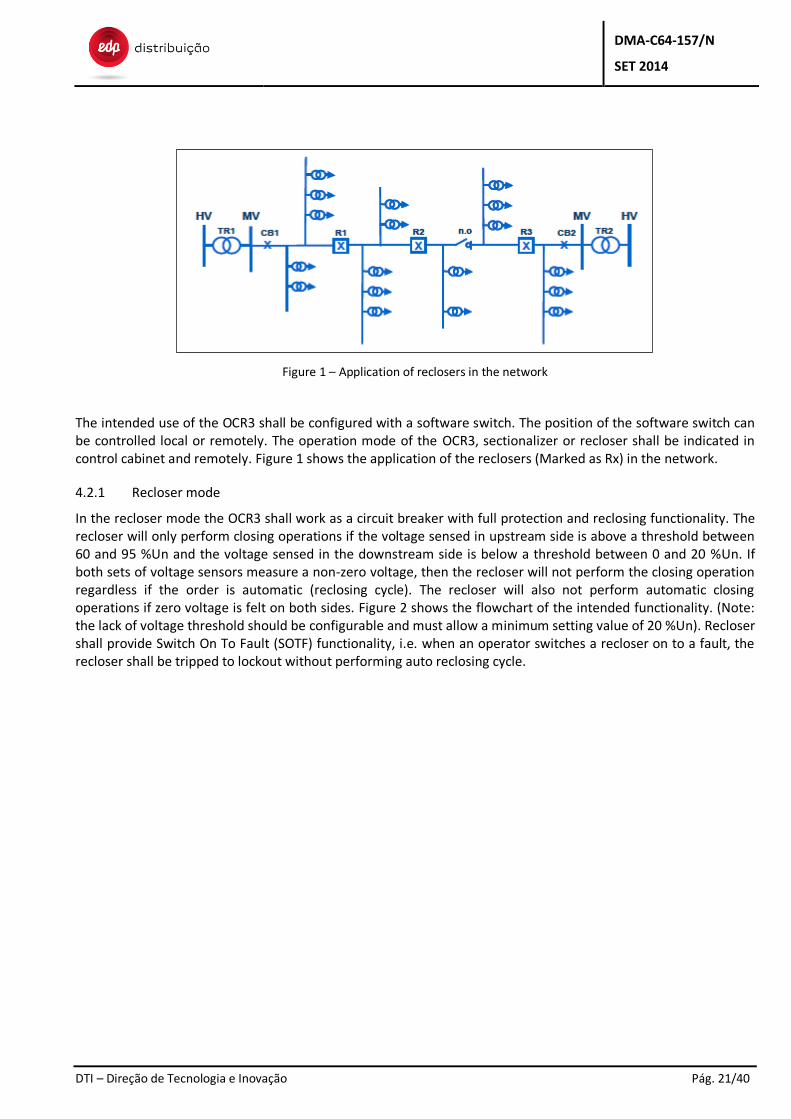
Figure 1 – Application of reclosers in the network
The intended use of the OCR3 shall be configured with a software switch. The position of the software switch can be controlled local or remotely. The operation mode of the OCR3, sectionalizer or recloser shall be indicated in control cabinet and remotely. Figure 1 shows the application of the reclosers (Marked as Rx) in the network.
4.2.1 Recloser mode
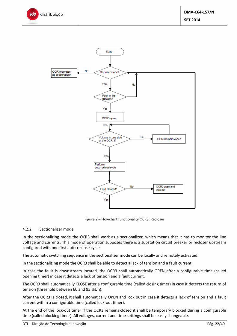
In the recloser mode the OCR3 shall work as a circuit breaker with full protection and reclosing functionality. The recloser will only perform closing operations if the voltage sensed in upstream side is above a threshold between 60 and 95 %Un and the voltage sensed in the downstream side is below a threshold between 0 and 20 %Un. If both sets of voltage sensors measure a non-zero voltage, then the recloser will not perform the closing operation regardless if the order is automatic (reclosing cycle). The recloser will also not perform automatic closing operations if zero voltage is felt on both sides. Figure 2 shows the flowchart of the intended functionality. (Note: the lack of voltage threshold should be configurable and must allow a minimum setting value of 20 %Un). Recloser shall provide Switch On To Fault (SOTF) functionality, i.e. when an operator switches a recloser on to a fault, the recloser shall be tripped to lockout without performing auto reclosing cycle.
DMA-C64-157/N
SET 2014
DTI – Direção de Tecnologia e Inovação Pág. 22/40
Figure 2 – Flowchart functionality OCR3: Recloser
4.2.2 Sectionalizer mode
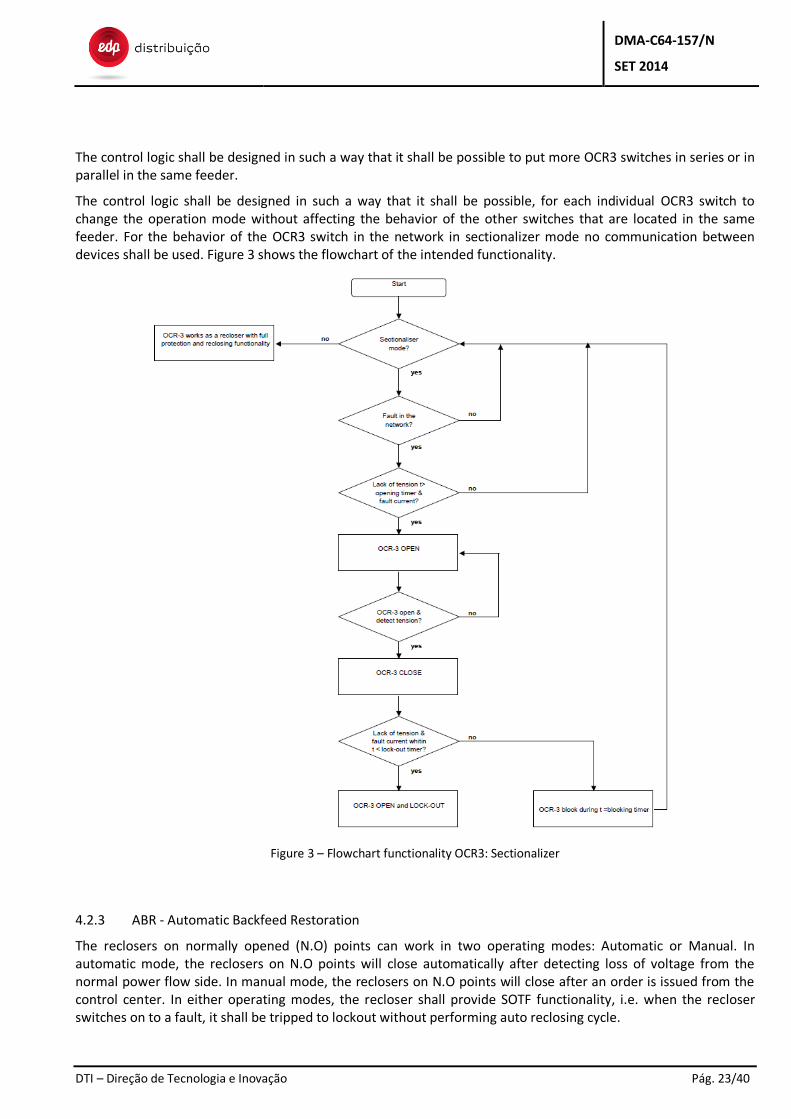
In the sectionalizing mode the OCR3 shall work as a sectionalizer, which means that it has to monitor the line voltage and currents. This mode of operation supposes there is a substation circuit breaker or recloser upstream configured with one first auto-reclose cycle.
The automatic switching sequence in the sectionalizer mode can be locally and remotely activated.
In the sectionalizing mode the OCR3 shall be able to detect a lack of tension and a fault current.
In case the fault is downstream located, the OCR3 shall automatically OPEN after a configurable time (called opening timer) in case it detects a lack of tension and a fault current.
The OCR3 shall automatically CLOSE after a configurable time (called closing timer) in case it detects the return of tension (threshold between 60 and 95 %Un).
After the OCR3 is closed, it shall automatically OPEN and lock out in case it detects a lack of tension and a fault current within a configurable time (called lock-out timer).
At the end of the lock-out timer if the OCR3 remains closed it shall be temporary blocked during a configurable time (called blocking timer). All voltages, current and time settings shall be easily changeable.
DMA-C64-157/N
SET 2014
DTI – Direção de Tecnologia e Inovação Pág. 23/40
The control logic shall be designed in such a way that it shall be possible to put more OCR3 switches in series or in parallel in the same feeder.
The control logic shall be designed in such a way that it shall be possible, for each individual OCR3 switch to change the operation mode without affecting the behavior of the other switches that are located in the same feeder. For the behavior of the OCR3 switch in the network in sectionalizer mode no communication between devices shall be used. Figure 3 shows the flowchart of the intended functionality.
Figure 3 – Flowchart functionality OCR3: Sectionalizer
4.2.3 ABR - Automatic Backfeed Restoration
The reclosers on normally opened (N.O) points can work in two operating modes: Automatic or Manual. In automatic mode, the reclosers on N.O points will close automatically after detecting loss of voltage from the normal power flow side. In manual mode, the reclosers on N.O points will close after an order is issued from the control center. In either operating modes, the recloser shall provide SOTF functionality, i.e. when the recloser switches on to a fault, it shall be tripped to lockout without performing auto reclosing cycle.
DMA-C64-157/N
SET 2014
DTI – Direção de Tecnologia e Inovação Pág. 24/40
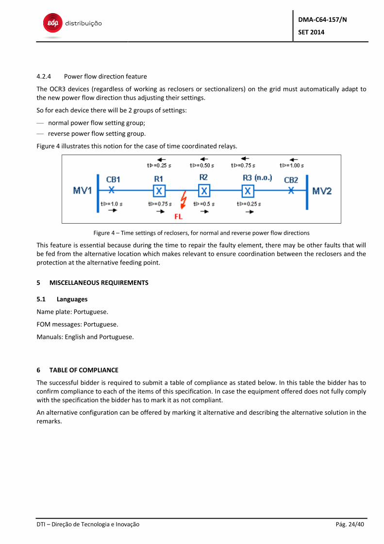
4.2.4 Power flow direction feature
The OCR3 devices (regardless of working as reclosers or sectionalizers) on the grid must automatically adapt to the new power flow direction thus adjusting their settings.
So for each device there will be 2 groups of settings:
— normal power flow setting group;
— reverse power flow setting group.
Figure 4 illustrates this notion for the case of time coordinated relays.
Figure 4 – Time settings of reclosers, for normal and reverse power flow directions
This feature is essential because during the time to repair the faulty element, there may be other faults that will be fed from the alternative location which makes relevant to ensure coordination between the reclosers and the protection at the alternative feeding point.
5 MISCELLANEOUS REQUIREMENTS
5.1 Languages
Name plate: Portuguese.
FOM messages: Portuguese.
Manuals: English and Portuguese.
6 TABLE OF COMPLIANCE
The successful bidder is required to submit a table of compliance as stated below. In this table the bidder has to confirm compliance to each of the items of this specification. In case the equipment offered does not fully comply with the specification the bidder has to mark it as not compliant.
An alternative configuration can be offered by marking it alternative and describing the alternative solution in the remarks.
DMA-C64-157/N
SET 2014
DTI – Direção de Tecnologia e Inovação Pág. 25/40
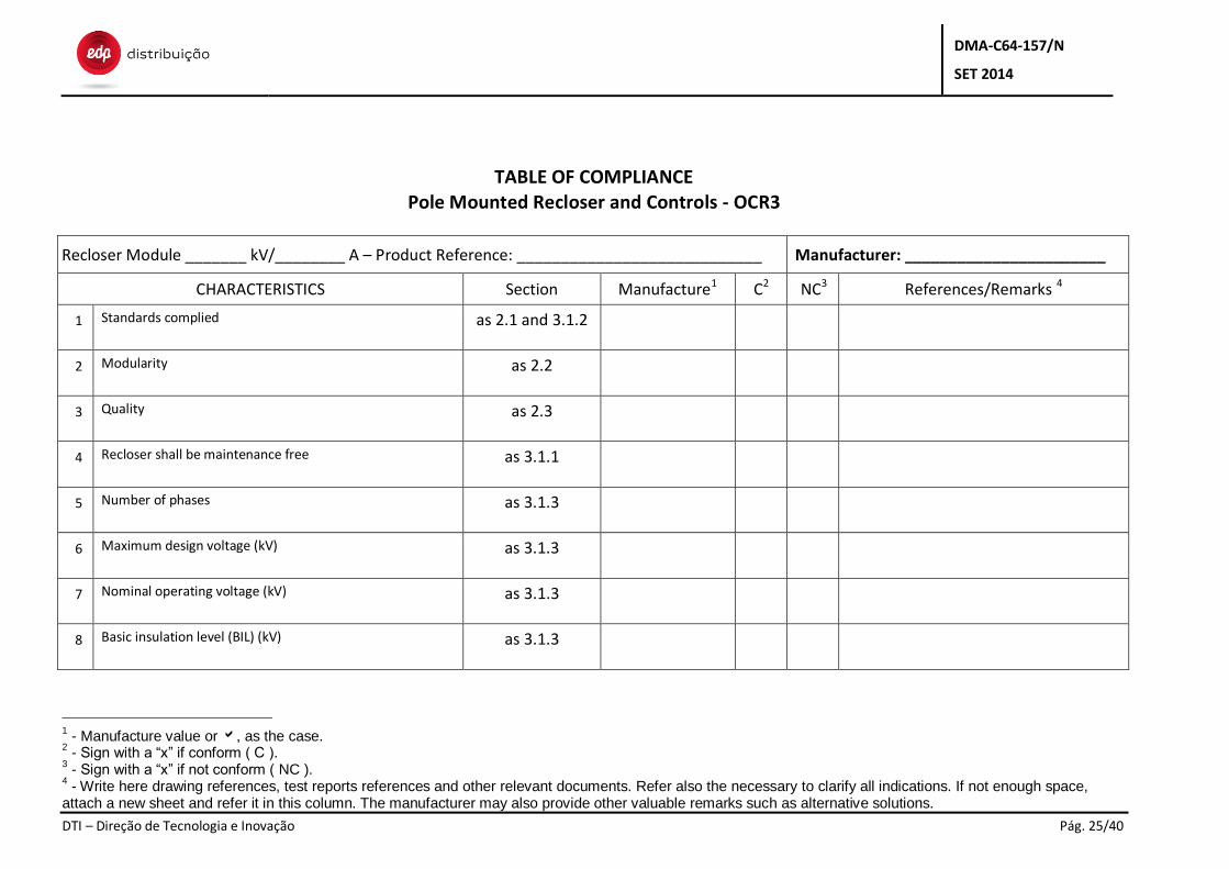
TABLE OF COMPLIANCE Pole Mounted Recloser and Controls - OCR3
Recloser Module _______ kV/________ A – Product Reference: ____________________________ Manufacturer: _______________________
CHARACTERISTICS Section Manufacture1 C2 NC3 References/Remarks 4
1 Standards complied as 2.1 and 3.1.2
2 Modularity as 2.2
3 Quality as 2.3
4 Recloser shall be maintenance free as 3.1.1
5 Number of phases as 3.1.3
6 Maximum design voltage (kV) as 3.1.3
7 Nominal operating voltage (kV) as 3.1.3
8 Basic insulation level (BIL) (kV) as 3.1.3
1 - Manufacture value or , as the case.
2 - Sign with a “x” if conform ( C ).
3 - Sign with a “x” if not conform ( NC ).
4 - Write here drawing references, test reports references and other relevant documents. Refer also the necessary to clarify all indications. If not enough space,
attach a new sheet and refer it in this column. The manufacturer may also provide other valuable remarks such as alternative solutions.
DMA-C64-157/N
SET 2014
DTI – Direção de Tecnologia e Inovação Pág. 26/40
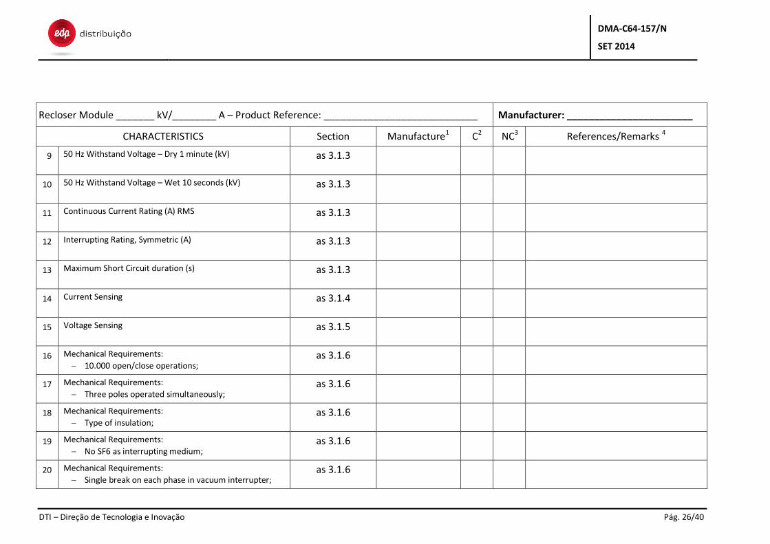
Recloser Module _______ kV/________ A – Product Reference: ____________________________ Manufacturer: _______________________
CHARACTERISTICS Section Manufacture1 C2 NC3 References/Remarks 4
9 50 Hz Withstand Voltage – Dry 1 minute (kV) as 3.1.3
10 50 Hz Withstand Voltage – Wet 10 seconds (kV) as 3.1.3
11 Continuous Current Rating (A) RMS as 3.1.3
12 Interrupting Rating, Symmetric (A) as 3.1.3
13 Maximum Short Circuit duration (s) as 3.1.3
14 Current Sensing as 3.1.4
15 Voltage Sensing as 3.1.5
16 Mechanical Requirements:
10.000 open/close operations; as 3.1.6
17 Mechanical Requirements:
Three poles operated simultaneously; as 3.1.6
18 Mechanical Requirements:
Type of insulation; as 3.1.6
19 Mechanical Requirements:
No SF6 as interrupting medium; as 3.1.6
20 Mechanical Requirements:
Single break on each phase in vacuum interrupter; as 3.1.6
DMA-C64-157/N
SET 2014
DTI – Direção de Tecnologia e Inovação Pág. 27/40
Recloser Module _______ kV/________ A – Product Reference: ____________________________ Manufacturer: _______________________
CHARACTERISTICS Section Manufacture1 C2 NC3 References/Remarks 4
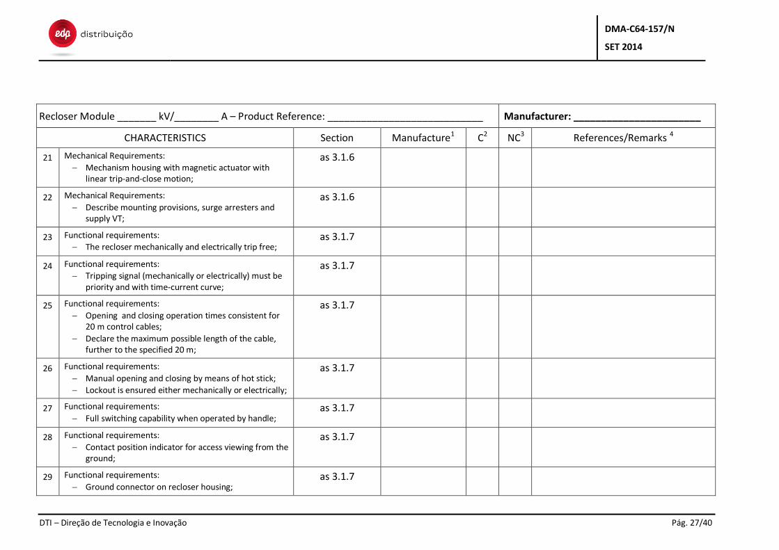
21 Mechanical Requirements:
Mechanism housing with magnetic actuator with linear trip-and-close motion;
as 3.1.6
22 Mechanical Requirements:
Describe mounting provisions, surge arresters and supply VT;
as 3.1.6
23 Functional requirements:
The recloser mechanically and electrically trip free; as 3.1.7
24 Functional requirements:
Tripping signal (mechanically or electrically) must be priority and with time-current curve;
as 3.1.7
25 Functional requirements:
Opening and closing operation times consistent for 20 m control cables;
Declare the maximum possible length of the cable, further to the specified 20 m;
as 3.1.7
26 Functional requirements:
Manual opening and closing by means of hot stick;
Lockout is ensured either mechanically or electrically;
as 3.1.7
27 Functional requirements:
Full switching capability when operated by handle; as 3.1.7
28 Functional requirements:
Contact position indicator for access viewing from the ground;
as 3.1.7
29 Functional requirements:
Ground connector on recloser housing; as 3.1.7
DMA-C64-157/N
SET 2014
DTI – Direção de Tecnologia e Inovação Pág. 28/40
Recloser Module _______ kV/________ A – Product Reference: ____________________________ Manufacturer: _______________________
CHARACTERISTICS Section Manufacture1 C2 NC3 References/Remarks 4
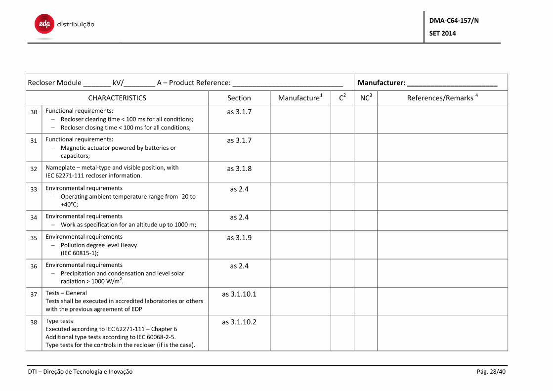
30 Functional requirements:
Recloser clearing time < 100 ms for all conditions;
Recloser closing time < 100 ms for all conditions;
as 3.1.7
31 Functional requirements:
Magnetic actuator powered by batteries or capacitors;
as 3.1.7
32 Nameplate – metal-type and visible position, with IEC 62271-111 recloser information.
as 3.1.8
33 Environmental requirements
Operating ambient temperature range from -20 to +40°C;
as 2.4
34 Environmental requirements
Work as specification for an altitude up to 1000 m; as 2.4
35 Environmental requirements
Pollution degree level Heavy (IEC 60815-1);
as 3.1.9
36 Environmental requirements
Precipitation and condensation and level solar radiation > 1000 W/m2.
as 2.4
37 Tests – General Tests shall be executed in accredited laboratories or others with the previous agreement of EDP
as 3.1.10.1
38 Type tests Executed according to IEC 62271-111 – Chapter 6 Additional type tests according to IEC 60068-2-5. Type tests for the controls in the recloser (if is the case).
as 3.1.10.2
DMA-C64-157/N
SET 2014
DTI – Direção de Tecnologia e Inovação Pág. 29/40
Recloser Module _______ kV/________ A – Product Reference: ____________________________ Manufacturer: _______________________
CHARACTERISTICS Section Manufacture1 C2 NC3 References/Remarks 4
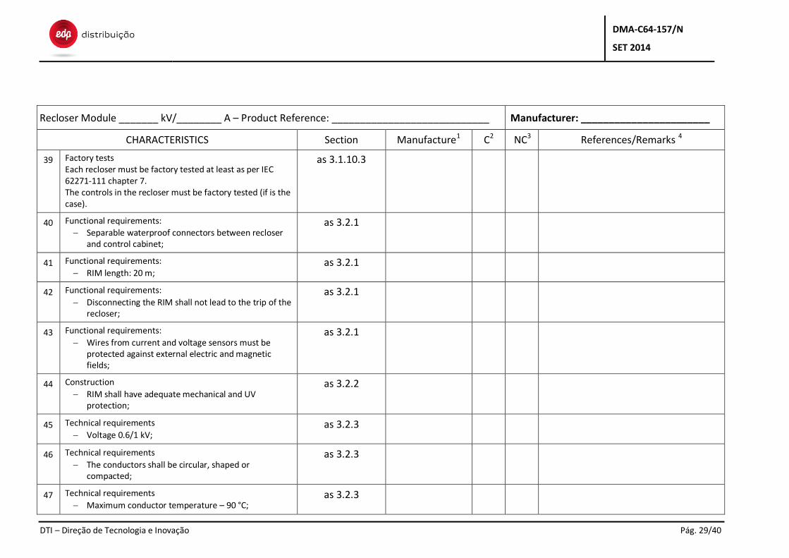
39 Factory tests Each recloser must be factory tested at least as per IEC 62271-111 chapter 7. The controls in the recloser must be factory tested (if is the case).
as 3.1.10.3
40 Functional requirements:
Separable waterproof connectors between recloser and control cabinet;
as 3.2.1
41 Functional requirements:
RIM length: 20 m; as 3.2.1
42 Functional requirements:
Disconnecting the RIM shall not lead to the trip of the recloser;
as 3.2.1
43 Functional requirements:
Wires from current and voltage sensors must be protected against external electric and magnetic fields;
as 3.2.1
44 Construction
RIM shall have adequate mechanical and UV protection;
as 3.2.2
45 Technical requirements
Voltage 0.6/1 kV; as 3.2.3
46 Technical requirements
The conductors shall be circular, shaped or compacted;
as 3.2.3
47 Technical requirements
Maximum conductor temperature – 90 °C; as 3.2.3
DMA-C64-157/N
SET 2014
DTI – Direção de Tecnologia e Inovação Pág. 30/40
Recloser Module _______ kV/________ A – Product Reference: ____________________________ Manufacturer: _______________________
CHARACTERISTICS Section Manufacture1 C2 NC3 References/Remarks 4
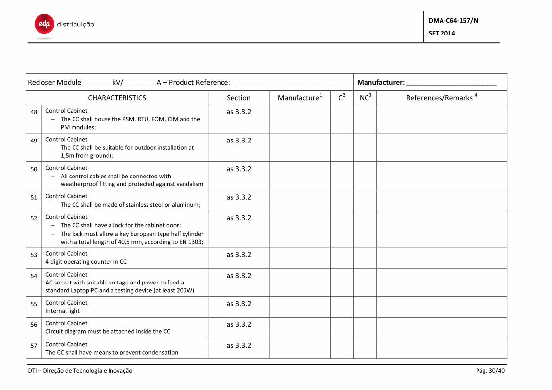
48 Control Cabinet
The CC shall house the PSM, RTU, FOM, CIM and the PM modules;
as 3.3.2
49 Control Cabinet
The CC shall be suitable for outdoor installation at 1,5m from ground);
as 3.3.2
50 Control Cabinet
All control cables shall be connected with weatherproof fitting and protected against vandalism
as 3.3.2
51 Control Cabinet
The CC shall be made of stainless steel or aluminum; as 3.3.2
52 Control Cabinet
The CC shall have a lock for the cabinet door;
The lock must allow a key European type half cylinder with a total length of 40,5 mm, according to EN 1303;
as 3.3.2
53 Control Cabinet 4 digit operating counter in CC
as 3.3.2
54 Control Cabinet AC socket with suitable voltage and power to feed a standard Laptop PC and a testing device (at least 200W)
as 3.3.2
55 Control Cabinet Internal light
as 3.3.2
56 Control Cabinet Circuit diagram must be attached inside the CC
as 3.3.2
57 Control Cabinet The CC shall have means to prevent condensation
as 3.3.2
DMA-C64-157/N
SET 2014
DTI – Direção de Tecnologia e Inovação Pág. 31/40
Recloser Module _______ kV/________ A – Product Reference: ____________________________ Manufacturer: _______________________
CHARACTERISTICS Section Manufacture1 C2 NC3 References/Remarks 4
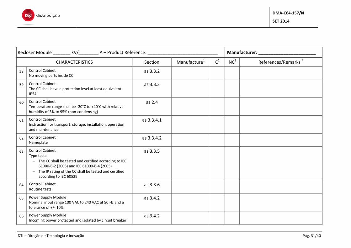
58 Control Cabinet No moving parts inside CC
as 3.3.2
59 Control Cabinet The CC shall have a protection level at least equivalent IP54.
as 3.3.3
60 Control Cabinet Temperature range shall be -20°C to +40°C with relative humidity of 5% to 95% (non-condensing)
as 2.4
61 Control Cabinet Instruction for transport, storage, installation, operation and maintenance
as 3.3.4.1
62 Control Cabinet Nameplate
as 3.3.4.2
63 Control Cabinet Type tests:
The CC shall be tested and certified according to IEC 61000-6-2 (2005) and IEC 61000-6-4 (2005)
The IP rating of the CC shall be tested and certified according to IEC 60529
as 3.3.5
64 Control Cabinet Routine tests
as 3.3.6
65 Power Supply Module Nominal input range 100 VAC to 240 VAC at 50 Hz and a tolerance of +/- 10%
as 3.4.2
66 Power Supply Module Incoming power protected and isolated by circuit breaker
as 3.4.2
DMA-C64-157/N
SET 2014
DTI – Direção de Tecnologia e Inovação Pág. 32/40
Recloser Module _______ kV/________ A – Product Reference: ____________________________ Manufacturer: _______________________
CHARACTERISTICS Section Manufacture1 C2 NC3 References/Remarks 4
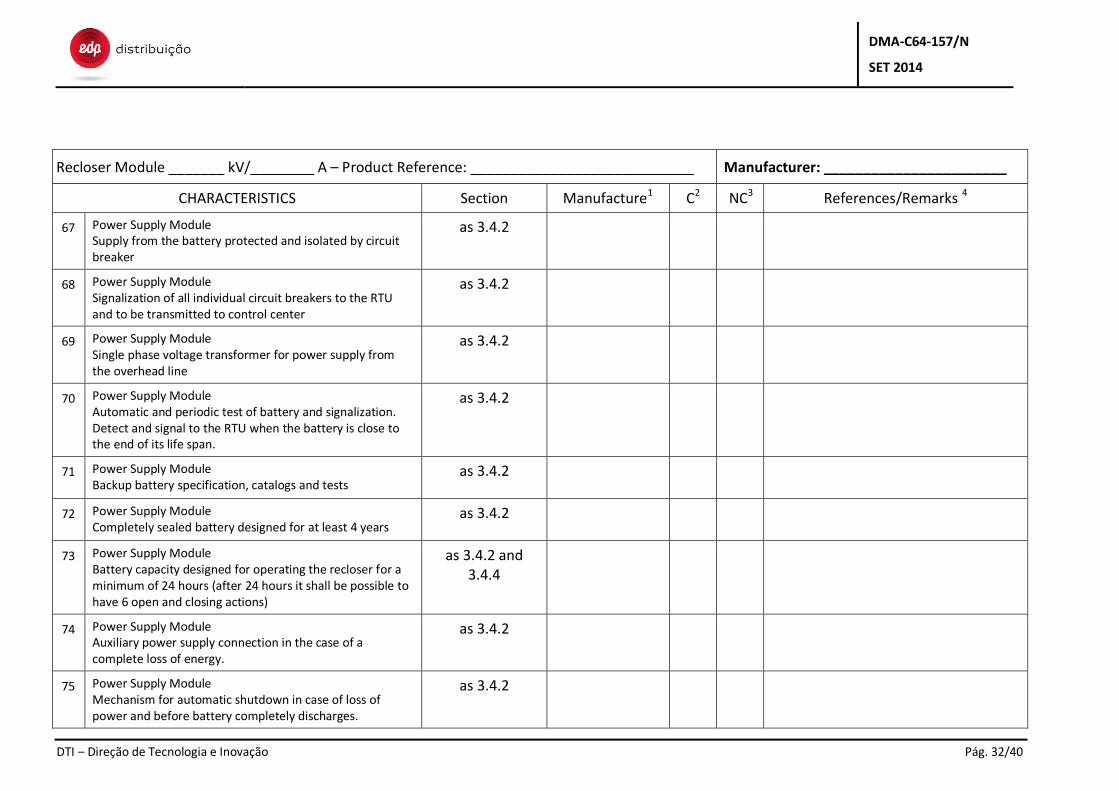
67 Power Supply Module Supply from the battery protected and isolated by circuit breaker
as 3.4.2
68 Power Supply Module Signalization of all individual circuit breakers to the RTU and to be transmitted to control center
as 3.4.2
69 Power Supply Module Single phase voltage transformer for power supply from the overhead line
as 3.4.2
70 Power Supply Module Automatic and periodic test of battery and signalization. Detect and signal to the RTU when the battery is close to the end of its life span.
as 3.4.2
71 Power Supply Module Backup battery specification, catalogs and tests
as 3.4.2
72 Power Supply Module Completely sealed battery designed for at least 4 years
as 3.4.2
73 Power Supply Module Battery capacity designed for operating the recloser for a minimum of 24 hours (after 24 hours it shall be possible to have 6 open and closing actions)
as 3.4.2 and 3.4.4
74 Power Supply Module Auxiliary power supply connection in the case of a complete loss of energy.
as 3.4.2
75 Power Supply Module Mechanism for automatic shutdown in case of loss of power and before battery completely discharges.
as 3.4.2
DMA-C64-157/N
SET 2014
DTI – Direção de Tecnologia e Inovação Pág. 33/40
Recloser Module _______ kV/________ A – Product Reference: ____________________________ Manufacturer: _______________________
CHARACTERISTICS Section Manufacture1 C2 NC3 References/Remarks 4
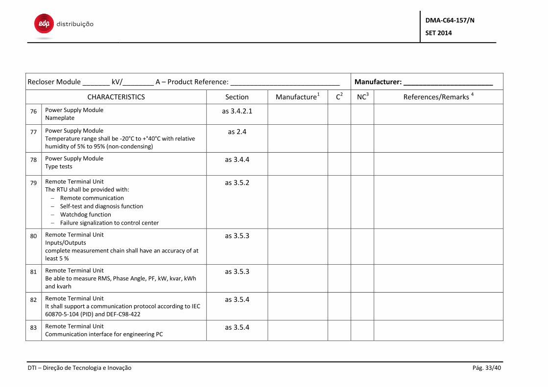
76 Power Supply Module Nameplate
as 3.4.2.1
77 Power Supply Module Temperature range shall be -20°C to +°40°C with relative humidity of 5% to 95% (non-condensing)
as 2.4
78 Power Supply Module Type tests
as 3.4.4
79 Remote Terminal Unit The RTU shall be provided with:
Remote communication
Self-test and diagnosis function
Watchdog function
Failure signalization to control center
as 3.5.2
80 Remote Terminal Unit Inputs/Outputs complete measurement chain shall have an accuracy of at least 5 %
as 3.5.3
81 Remote Terminal Unit Be able to measure RMS, Phase Angle, PF, kW, kvar, kWh and kvarh
as 3.5.3
82 Remote Terminal Unit It shall support a communication protocol according to IEC 60870-5-104 (PID) and DEF-C98-422
as 3.5.4
83 0 Remote Terminal Unit Communication interface for engineering PC
as 3.5.4
DMA-C64-157/N
SET 2014
DTI – Direção de Tecnologia e Inovação Pág. 34/40
Recloser Module _______ kV/________ A – Product Reference: ____________________________ Manufacturer: _______________________
CHARACTERISTICS Section Manufacture1 C2 NC3 References/Remarks 4
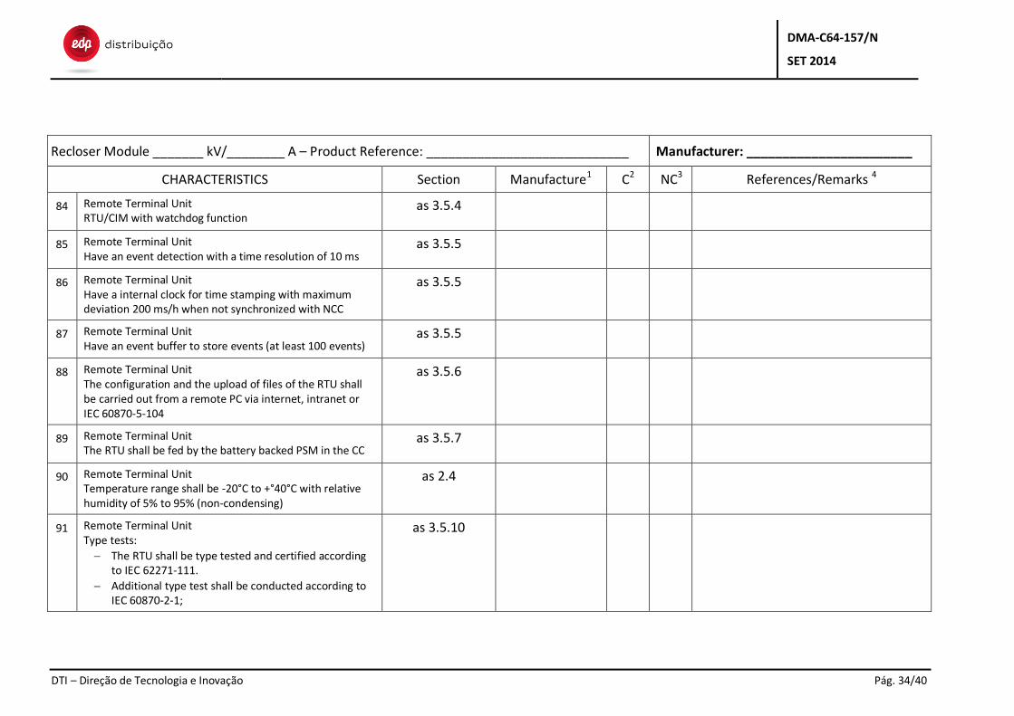
84 Remote Terminal Unit RTU/CIM with watchdog function
as 3.5.4
85 2 Remote Terminal Unit Have an event detection with a time resolution of 10 ms
as 3.5.5
86 Remote Terminal Unit Have a internal clock for time stamping with maximum deviation 200 ms/h when not synchronized with NCC
as 3.5.5
87 Remote Terminal Unit Have an event buffer to store events (at least 100 events)
as 3.5.5
88 Remote Terminal Unit The configuration and the upload of files of the RTU shall be carried out from a remote PC via internet, intranet or IEC 60870-5-104
as 3.5.6
89 Remote Terminal Unit The RTU shall be fed by the battery backed PSM in the CC
as 3.5.7
90 Remote Terminal Unit Temperature range shall be -20°C to +°40°C with relative humidity of 5% to 95% (non-condensing)
as 2.4
91 Remote Terminal Unit Type tests:
The RTU shall be type tested and certified according to IEC 62271-111.
Additional type test shall be conducted according to IEC 60870-2-1;
as 3.5.10
DMA-C64-157/N
SET 2014
DTI – Direção de Tecnologia e Inovação Pág. 35/40
Recloser Module _______ kV/________ A – Product Reference: ____________________________ Manufacturer: _______________________
CHARACTERISTICS Section Manufacture1 C2 NC3 References/Remarks 4
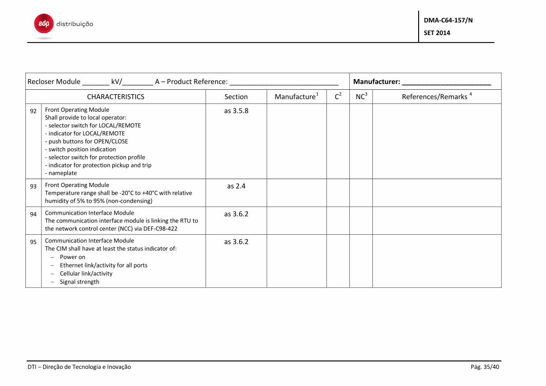
92 Front Operating Module Shall provide to local operator: - selector switch for LOCAL/REMOTE - indicator for LOCAL/REMOTE - push buttons for OPEN/CLOSE - switch position indication - selector switch for protection profile - indicator for protection pickup and trip - nameplate
as 3.5.8
93 Front Operating Module Temperature range shall be -20°C to +40°C with relative humidity of 5% to 95% (non-condensing)
as 2.4
94 Communication Interface Module The communication interface module is linking the RTU to the network control center (NCC) via DEF-C98-422
as 3.6.2
95 Communication Interface Module The CIM shall have at least the status indicator of:
Power on
Ethernet link/activity for all ports
Cellular link/activity
Signal strength
as 3.6.2
DMA-C64-157/N
SET 2014
DTI – Direção de Tecnologia e Inovação Pág. 36/40
Recloser Module _______ kV/________ A – Product Reference: ____________________________ Manufacturer: _______________________
CHARACTERISTICS Section Manufacture1 C2 NC3 References/Remarks 4
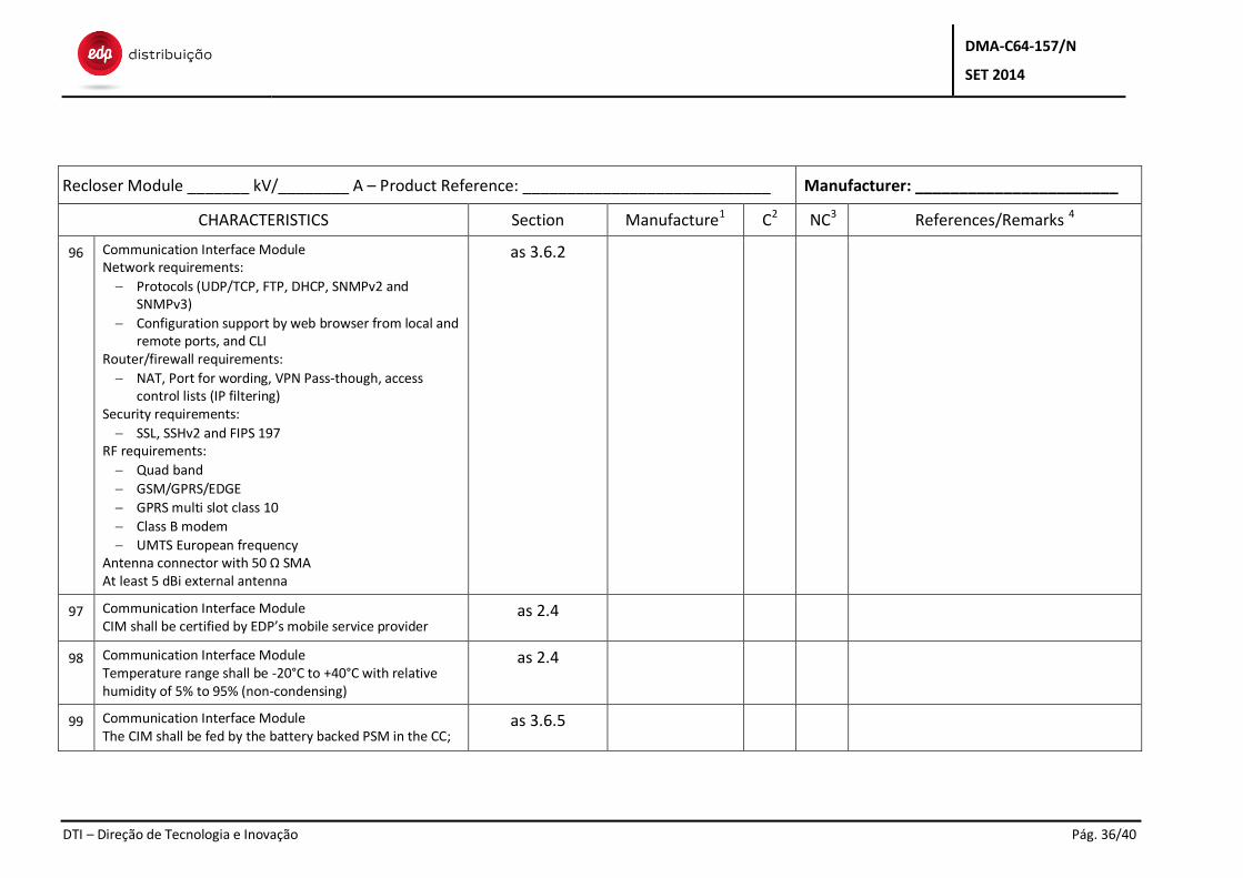
96 Communication Interface Module Network requirements:
Protocols (UDP/TCP, FTP, DHCP, SNMPv2 and SNMPv3)
Configuration support by web browser from local and remote ports, and CLI
Router/firewall requirements:
NAT, Port for wording, VPN Pass-though, access control lists (IP filtering)
Security requirements:
SSL, SSHv2 and FIPS 197 RF requirements:
Quad band
GSM/GPRS/EDGE
GPRS multi slot class 10
Class B modem
UMTS European frequency Antenna connector with 50 Ω SMA At least 5 dBi external antenna
as 3.6.2
97 Communication Interface Module CIM shall be certified by EDP’s mobile service provider
as 2.4
98 Communication Interface Module Temperature range shall be -20°C to +40°C with relative humidity of 5% to 95% (non-condensing)
as 2.4
99 Communication Interface Module The CIM shall be fed by the battery backed PSM in the CC;
as 3.6.5
DMA-C64-157/N
SET 2014
DTI – Direção de Tecnologia e Inovação Pág. 37/40
Recloser Module _______ kV/________ A – Product Reference: ____________________________ Manufacturer: _______________________
CHARACTERISTICS Section Manufacture1 C2 NC3 References/Remarks 4
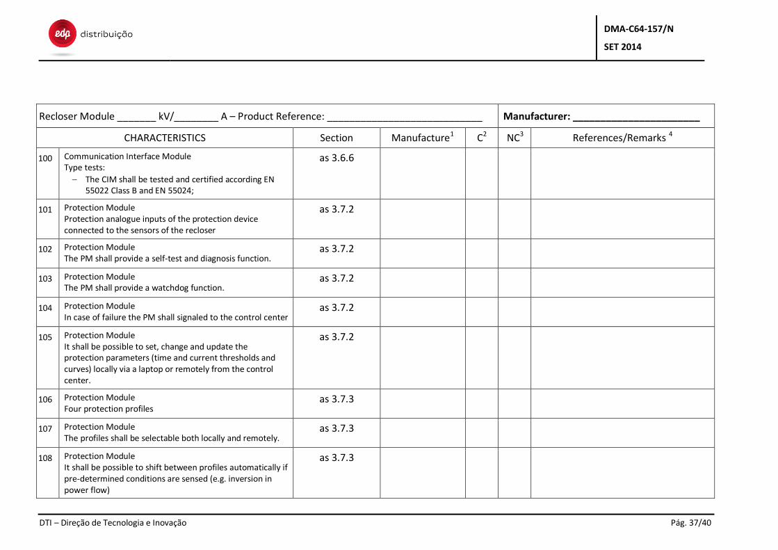
100 Communication Interface Module Type tests:
The CIM shall be tested and certified according EN 55022 Class B and EN 55024;
as 3.6.6
101 Protection Module Protection analogue inputs of the protection device connected to the sensors of the recloser
as 3.7.2
102 Protection Module The PM shall provide a self-test and diagnosis function.
as 3.7.2
103 Protection Module The PM shall provide a watchdog function.
as 3.7.2
104 Protection Module In case of failure the PM shall signaled to the control center
as 3.7.2
105 Protection Module It shall be possible to set, change and update the protection parameters (time and current thresholds and curves) locally via a laptop or remotely from the control center.
as 3.7.2
106 Protection Module Four protection profiles
as 3.7.3
107 Protection Module The profiles shall be selectable both locally and remotely.
as 3.7.3
108 Protection Module It shall be possible to shift between profiles automatically if pre-determined conditions are sensed (e.g. inversion in power flow)
as 3.7.3
DMA-C64-157/N
SET 2014
DTI – Direção de Tecnologia e Inovação Pág. 38/40
Recloser Module _______ kV/________ A – Product Reference: ____________________________ Manufacturer: _______________________
CHARACTERISTICS Section Manufacture1 C2 NC3 References/Remarks 4
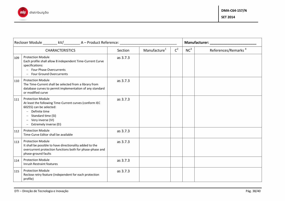
109 Protection Module Each profile shall allow 8 independent Time-Current Curve specifications:
Four Phase Overcurrents
Four Ground Overcurrents
as 3.7.3
110 Protection Module The Time-Current shall be selected from a library from database curves to permit implementation of any standard or modified curve
as 3.7.3
111 Protection Module At least the following Time-Current curves (conform IEC 60255) can be selected:
Definite time
Standard time (SI)
Very inverse (VI)
Extremely inverse (EI)
as 3.7.3
112 Protection Module Time-Curve Editor shall be available
as 3.7.3
113 Protection Module It shall be possible to have directionality added to the overcurrent protection functions both for phase-phase and phase-ground faults
as 3.7.3
114 Protection Module Inrush Restraint features
as 3.7.3
115 Protection Module Reclose retry feature (independent for each protection profile)
as 3.7.3
DMA-C64-157/N
SET 2014
DTI – Direção de Tecnologia e Inovação Pág. 39/40
Recloser Module _______ kV/________ A – Product Reference: ____________________________ Manufacturer: _______________________
CHARACTERISTICS Section Manufacture1 C2 NC3 References/Remarks 4
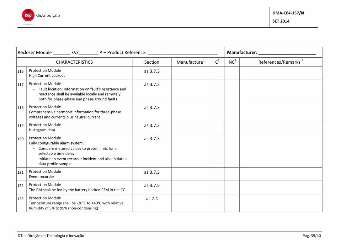
116 Protection Module High Current Lockout
as 3.7.3
117 Protection Module
Fault location: Information on fault’s resistance and reactance shall be available locally and remotely, both for phase-phase and phase-ground faults
as 3.7.3
118 Protection Module Comprehensive harmonic information for three-phase voltages and currents plus neutral current
as 3.7.3
119 Protection Module Histogram data
as 3.7.3
120 Protection Module Fully configurable alarm system:
Compare metered values to preset limits for a selectable time delay
Initiate an event recorder incident and also initiate a data profile sample
as 3.7.3
121 Protection Module Event recorder
as 3.7.3
122 Protection Module The PM shall be fed by the battery backed PSM in the CC
as 3.7.5
123 Protection Module Temperature range shall be -20°C to +40°C with relative humidity of 5% to 95% (non-condensing)
as 2.4
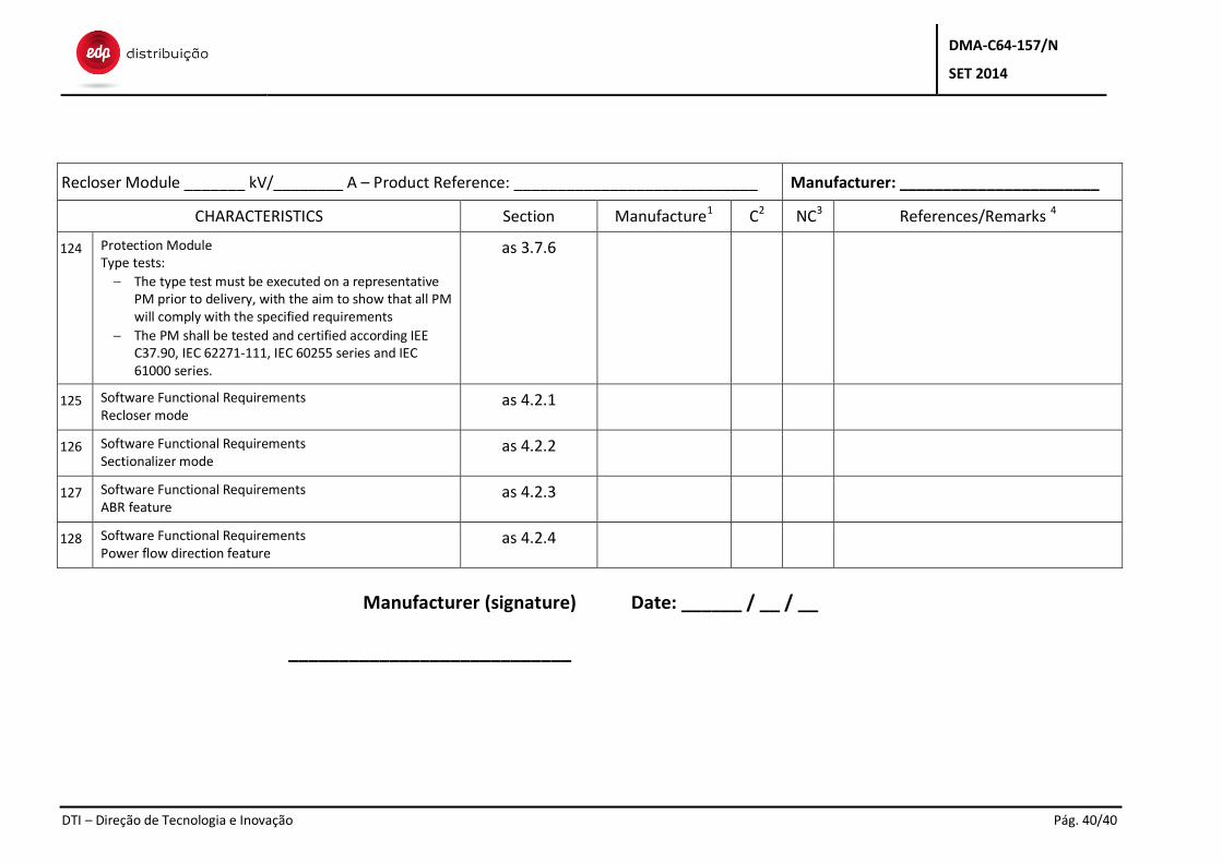
DMA-C64-157/N
SET 2014
DTI – Direção de Tecnologia e Inovação Pág. 40/40
Recloser Module _______ kV/________ A – Product Reference: ____________________________ Manufacturer: _______________________
CHARACTERISTICS Section Manufacture1 C2 NC3 References/Remarks 4
124 Protection Module Type tests:
The type test must be executed on a representative PM prior to delivery, with the aim to show that all PM will comply with the specified requirements
The PM shall be tested and certified according IEE C37.90, IEC 62271-111, IEC 60255 series and IEC 61000 series.
as 3.7.6
125 Software Functional Requirements Recloser mode
as 4.2.1
126 Software Functional Requirements Sectionalizer mode
as 4.2.2
127 Software Functional Requirements ABR feature
as 4.2.3
128 Software Functional Requirements Power flow direction feature
as 4.2.4
Manufacturer (signature) Date: ______ / __ / __
____________________________