Embed Size (px)
Citation preview
Walt Disney World Swan and Dolphin ResortOrlando, Florida
12/1/2005 - 8:00 am - 11:30 am Room:Swan 4 (Swan)
Mastering Corridor Transitions and Superelevation with Autodesk® Civil 3D® 2006
The depth, flexibility, and automation of Civil 3D 2006's corridor system make it a must for anyone tackling complex rail and highway designs. This course will consider methods of applying horizontal and vertical transitions and superelevation controls by examining the alignment, profile and corridor systems in depth. This class will benefit civil engineering professionals, CAD/IT managers, and even project managers and DOT/MOT personnel interested in learning about the power of Civil 3D for complex design projects.
CV41-3
About the Speaker:
Michael Choquette - SageCAD/IMAGINiTPhillip Zimmermanand
Mike is a civil engineer, technical author and software instructor specializing in transportation, environmental engineering, and visualization. His software expertise is concentrated on the Civil 3D, Map 3D, 3ds Max and VIZ products. He has worked as a design engineer in the Boston area and as a software instructor for two leading Autodesk resellers. Mike has a Masters of Science degree in Civil Engineering and is a registered Professional Engineer in the State of Massachusetts. His publication credits include contributions to conference proceedings and John Wiley & Son's Encyclopedia of Environmental Analysis and [email protected]
Phillip has two degrees in Geography, one from the University of New Mexico and a Masters from Western Michigan University. Phillip started as a draftsman at a small survey office plats and civil engineering designs. Following his work in the survey department, he led the CAD department of a infrastructure management company. For eight years, starting in 1990 he became an instructor for Land Desktop, Civil Design, and Survey a one of Chicago’s largest instrument sales offices. While there he published his 1st edition of the Harnessing Land Desktop. In 1998 Phillip joined Autodesk as a Civil AE and later relocated to Manchester to become Technical Marketing Manager of the ISD. Phillip is the National Trainer for Civil IMAGINiT.


Mastering Corridor Transitions and Superelevation
2
About the Speakers:
Mike Choquette is a civil engineer, technical author and software instructor specializing in transportation, environmental engineering, and visualization. His software expertise is concentrated on the Civil 3D, Map 3D, 3ds max and VIZ products. He has worked as a design engineer in the Boston area and as a software instructor for two leading Autodesk resellers. Mike has a Masters of Science degree in Civil Engineering and is a registered Professional Engineer in the State of Massachusetts. His publication credits include contributions to conference proceedings and John Wiley & Son's Encyclopedia of Environmental Analysis and Remediation. [email protected]
Phil Zimmerman is a technical author and instructor specializing in transportation, subdivision, and survey. His software expertise includes Land Desktop, Civil 3D, Map 3D, Survey, Raster Design. He has worked at Survey and Civil Engineering offices, instructed AutoCAD products in the Chicago and New England areas. Phillip has a Masters of Arts in Geography and is the author of Harnessing Land Desktop 2005.
Mastering Corridor Transitions and Superelevation
3
Introduction
Autodesk Civil 3D is the future replacement for Autodesk’s Land Desktop and Civil Design products. Civil 3D 2006, now in its second full release, is starting to come into its own. One of the most impressive areas of improvement over Land Desktop and Civil Design is Civil 3D’s Corridor Design system, which replaces the road design tools of Civil Design. This system has the general title of “corridor” design since it is equally applicable to roads, railbeds, bike paths, levees, designed ditches and swales; in fact many different kinds of linear design project.
This course will illustrate how to apply complex, varying cross-sections (horizontal and vertical transitions) and superelevation to Civil 3D 2006 corridors. As this is an intermediate class, it is assumed that attendees are already familiar with creating horizontal alignments, surface profiles and proposed vertical alignments in Civil 3D. (There are other classes available at this year’s Autodesk University that cover these topics in depth, if a review would be helpful.)
Some of the greatest resources to anyone interested in Civil 3D are the weekly informational webcasts provided by Autodesk. Recorded versions of previous webcasts (as well as information on how to attend future webcasts) are available from Autodesk’s web site. From the home page www.autodesk.com click on “Products”, then “Civil 3D”, then “Demonstration”, followed by “Autodesk Civil 3D Webcasts”.
Overview of Civil 3D Assemblies and Corridors
The corridor system results in the creation of corridor objects – 3D representations of your project based on one or more horizontal and vertical alignments and proposed cross sections (proposed cross-sections are referred to as assemblies in Civil 3D). As with almost every aspect of Civil 3D, these corridor objects remain dynamically linked to the features they are based on. In other words if you adjust a horizontal alignment, vertical alignment or an assembly the corridor object can be updated to show the results. Following an automatic or on-demand update, surfaces that can be generated from the corridor (such as one showing contours across the proposed “top surface”) and quantity takeoffs can be automatically regenerated as well.
Overview of Assemblies
The core elements of the corridor system are assemblies and their component subassemblies. (Civil 3D subassemblies are a new concept and do not correlate to Civil Design’s subassemblies.) The assembly object is essentially an anchor that you use to represent the profile grade point in the proposed cross section. This usually translates into the crown point of a 2-lane roadway. Once you have located an assembly object in your drawing (Corridors > Create Assembly) you then attach subassemblies to

Mastering Corridor Transitions and Superelevation
4
it. Subassemblies are individual sections of a proposed roadway, such as a section of full-depth pavement, a curbing with sub-base layer below it, a grass strip, etc. A large number of sophisticated assembles are available out-of-the-box and you can create your own components from polylines or “links”. (Creating your own custom subassemblies is disused in other courses at this year’s Autodesk University.) The stock subassemblies can be browsed through the Civil 3D Catalog (General > Catalog) or through several pre-configured tool palettes, shown in the in illustration below.
Civil 3D subassemblies are highly customizable through their object properties. For example, the lane section subassemblies shown above have width, depth and slope parameters. These numeric parameters allow the same subassembly to represent dozens of different design scenarios. It also means that if you want to change a lane width, for example, all you need to do is change the width parameter. Subassemblies can be added to an assembly quickly and accurately by choosing a desired component in a tool palette and then clicking on the assembly (for components located at the baseline) or by clicking on the circles (linkage points, called markers) located along other subassemblies. In this way you build a completed assembly by “stringing together” one subassembly at a time.
Mastering Corridor Transitions and Superelevation
5
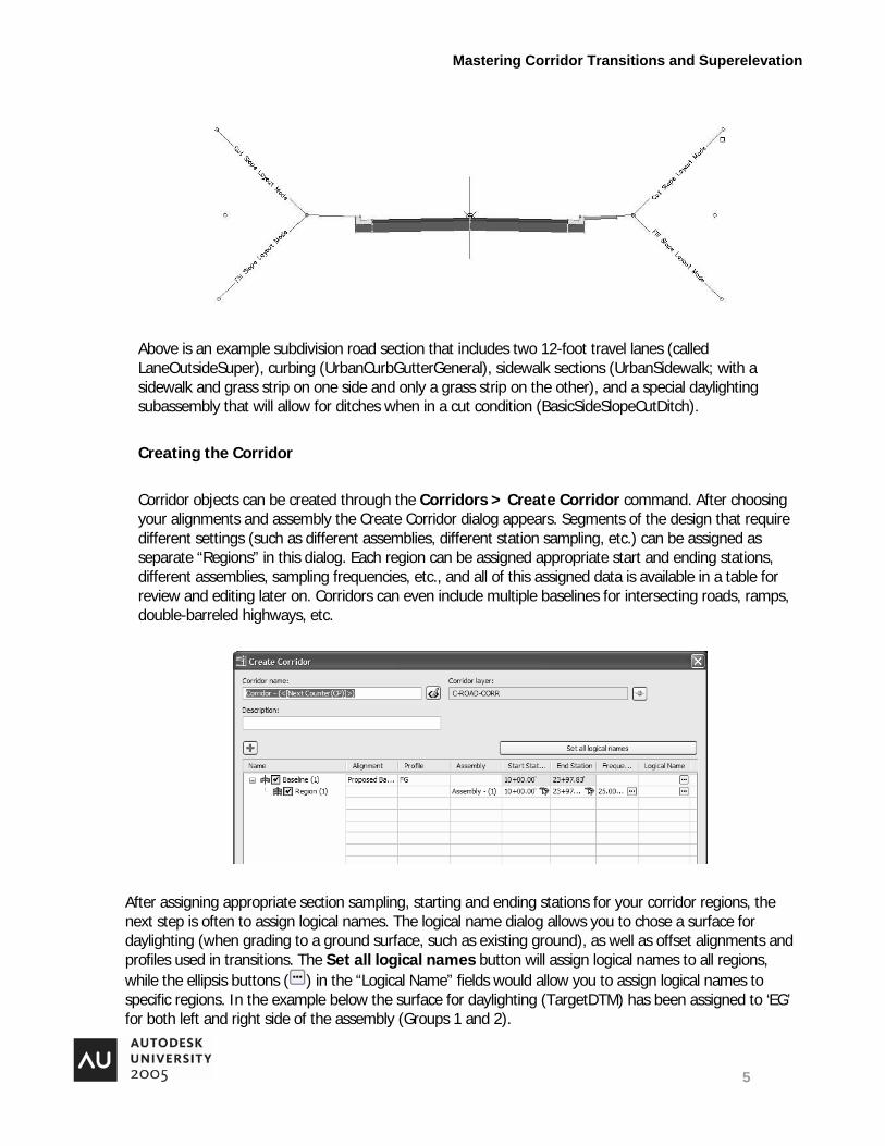
Above is an example subdivision road section that includes two 12-foot travel lanes (called LaneOutsideSuper), curbing (UrbanCurbGutterGeneral), sidewalk sections (UrbanSidewalk; with a sidewalk and grass strip on one side and only a grass strip on the other), and a special daylighting subassembly that will allow for ditches when in a cut condition (BasicSideSlopeCutDitch).
Creating the Corridor
Corridor objects can be created through the Corridors > Create Corridor command. After choosing your alignments and assembly the Create Corridor dialog appears. Segments of the design that require different settings (such as different assemblies, different station sampling, etc.) can be assigned as separate “Regions” in this dialog. Each region can be assigned appropriate start and ending stations, different assemblies, sampling frequencies, etc., and all of this assigned data is available in a table for review and editing later on. Corridors can even include multiple baselines for intersecting roads, ramps, double-barreled highways, etc.
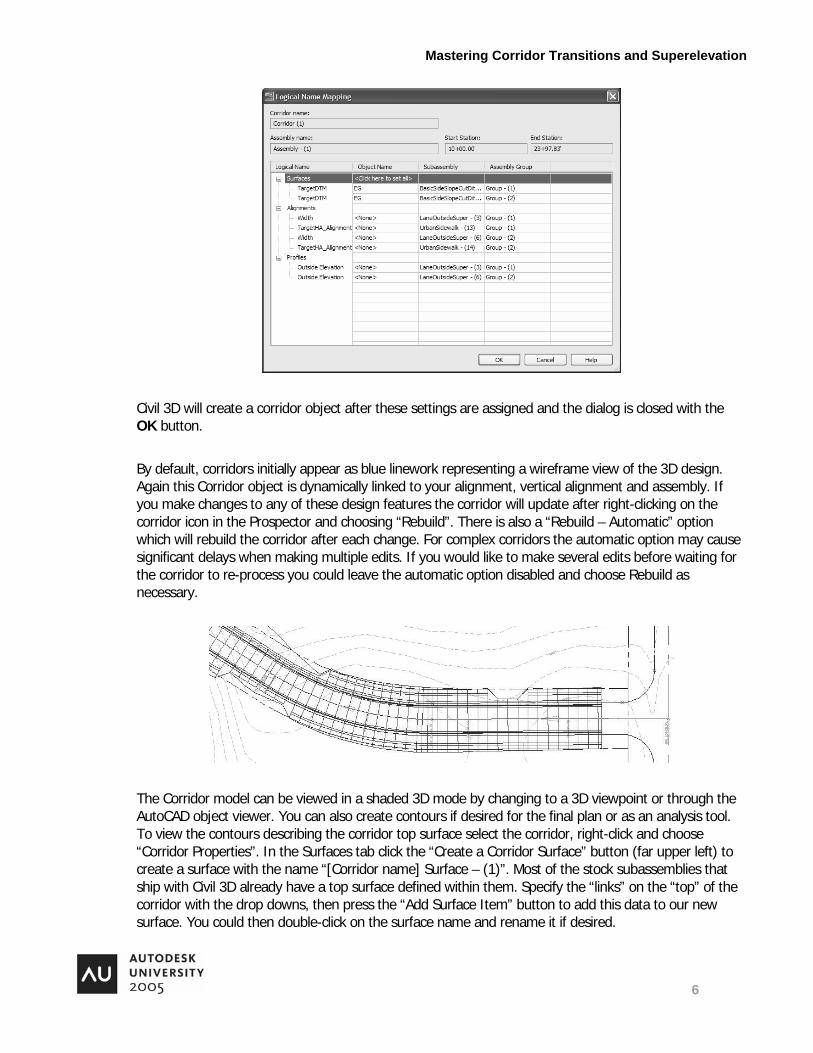
After assigning appropriate section sampling, starting and ending stations for your corridor regions, the next step is often to assign logical names. The logical name dialog allows you to chose a surface for daylighting (when grading to a ground surface, such as existing ground), as well as offset alignments and profiles used in transitions. The Set all logical names button will assign logical names to all regions, while the ellipsis buttons ( ) in the “Logical Name” fields would allow you to assign logical names to specific regions. In the example below the surface for daylighting (TargetDTM) has been assigned to ‘EG’ for both left and right side of the assembly (Groups 1 and 2).
Mastering Corridor Transitions and Superelevation
6
Civil 3D will create a corridor object after these settings are assigned and the dialog is closed with the OK button.
By default, corridors initially appear as blue linework representing a wireframe view of the 3D design. Again this Corridor object is dynamically linked to your alignment, vertical alignment and assembly. If you make changes to any of these design features the corridor will update after right-clicking on the corridor icon in the Prospector and choosing “Rebuild”. There is also a “Rebuild – Automatic” option which will rebuild the corridor after each change. For complex corridors the automatic option may cause significant delays when making multiple edits. If you would like to make several edits before waiting for the corridor to re-process you could leave the automatic option disabled and choose Rebuild as necessary.
The Corridor model can be viewed in a shaded 3D mode by changing to a 3D viewpoint or through the AutoCAD object viewer. You can also create contours if desired for the final plan or as an analysis tool. To view the contours describing the corridor top surface select the corridor, right-click and choose “Corridor Properties”. In the Surfaces tab click the “Create a Corridor Surface” button (far upper left) to create a surface with the name “[Corridor name] Surface – (1)”. Most of the stock subassemblies that ship with Civil 3D already have a top surface defined within them. Specify the “links” on the “top” of the corridor with the drop downs, then press the “Add Surface Item” button to add this data to our new surface. You could then double-click on the surface name and rename it if desired.

Mastering Corridor Transitions and Superelevation
7
To view the contours describing this top surface, give the surface a style that displays contours (such as the default “Border and Contours” surface style available in the _Autodesk Civil 3D Imperial By Layer.dwt template).
Corridor surfaces often benefit from a boundary that limits the surface to the width of the corridor itself (preventing triangulation across the inside of a corner, for example). For assemblies that include a daylight subassembly on both sides this usually can be accomplished easily through an automatic “daylight” boundary. To add one, in the boundary tab of the Corridor Property dialog right-click on the surface name and “Add Automatically” a Daylight boundary. Click the OK button to complete the surface definition. Surfaces created through corridors will also remain dynamically linked to the design alignments and assembly; rebuilding a corridor will also rebuild these surfaces.

Mastering Corridor Transitions and Superelevation
8
Simple Transitions Civil 3D can transition proposed cross-sections over varying conditions, such as horizontally stretching or contracting to represent lane addition or removal. For example, the corridor below is shown on the left as defined with a constant width. The graphic on the right shows the lane section widening from one lane into two, in order to make room for a right-turn lane. Civil 3D can also apply vertical transitions as well, to allow a point in the cross section to follow a specific profile.
By modeling a corridor with transitions you are able to create a dynamic design model that can accurately represent the proposed condition. The advantages of having this kind of design model include:
• Automatic contour creation that takes into account the varying conditions
• Accurate proposed cross-sections that represent varying conditions (saving you the effort of manually drafting each one)
• Accurate, dynamic volume calculations for quantity takeoffs
Horizontal transitions are defined by “offset” alignments. In the example above the right edge of pavement is defined as a new alignment called “R EOP”. Since horizontal transition (offset) alignments do not need to be used as baselines, their stationing and the direction do not need to match or line up with other baselines (such as the road centerline).
Many subassemblies (including the LaneOutsideSuper subassemblies used in the previous example) have built-in controls for width and outside elevation. To assign a transition select the corridor, right-click and choose “Corridor Properties”. In the parameters tab press the ellipsis button ( ) in the “Logical Name” field for the transitioning region to call up the Logical Name Dialog. When using a LaneOutsideSuper subassembly notice that there are fields available that can be used to define the “width” and “outside elevation” of each LaneOutsideSuper subassembly. As another example, the UrbanSidewalk subassembly also has a width parameter that can be controlled by anther alignment (called “Target_HA_Alignment”).

Mastering Corridor Transitions and Superelevation
9
To attach an offset (horizontal) alignment or profile (vertical alignment) simply choose the desired alignment or profile from the Object Name field.
Corridors can also be transitioned vertically as well. The dialog above shows areas where the outside lane elevations can be assigned a vertical alignment (under Profiles). These controls allow you to raise or lower a lane edge independently from the baseline, or even match an existing ground edge profile. One way to begin a proposed edge profile would be to copy and lower the proposed centerline vertical alignment. With the centerline selected, right-click and choose Edit Profile. In the Edit Profile toolbar
click the Copy Profile button . Your copied profile can later be renamed through the Prospector tab of
the Civil 3D Toolspace. Select your copied profile and click the Raise/Lower PVIs button to lower it the height difference between the baseline and the point to be transitioned (such as the lane edge). From there that edge profile can be refined as necessary. Other transition profiles can be created in the same way, such as a different edge profile on the other side of the road. Once these proposed vertical alignments are created they can be assigned similarly to horizontal offset alignments in the Logical Name Dialog of Corridor Properties (above).

Mastering Corridor Transitions and Superelevation
10
Assembly Offsets
Subassemblies normally appear perpendicular to the baseline at all points. In the example above the curbing along the transition region remained perpendicular to the baseline, where it may have been better represented perpendicular to the transition alignment. The graphics below illustrate this point in a more dramatic example of a curb and gutter section being transitioned around the edge of a parking lot. At one point the curb and gutter section wind up at nearly a right angle to the way they would be constructed.
Assembly Offsets allow the designer to orient subassemblies perpendicular to an offset alignment (such as the transition itself) rather than the baseline. Doing so in this case would result in the following layout of that same curb and gutter section shown above:
To add an assembly offset to an existing assembly either choose Corridors > Create Assembly Offset or select an assembly, right-click and choose “Add Offset”. Offsets appear in an assembly as a vertical line. The Assembly below indicates two offsets, one on each side:

Mastering Corridor Transitions and Superelevation
11
Locate the offset on the assembly as you would a subassembly. Subassembly components that are to be oriented by the offset should then be attached directly to the offset line. (Above, the curb and gutter sections were attached to the offset lines rather than the lanes.)
There is an excellent recorded webcast provided by Autodesk that outlines the use of assembly offsets titled, “Cul-des-sac and Knuckle Design Using Autodesk Civil 3D”. These webcasts are described in the introduction to this document. https://www112.livemeeting.com/cc/autodesklearning/view?id=Civil0114&pw=Civil3D
Here are some points to keep in mind when working with Assembly Offsets and complex corridors:
• The parking lot example above has several additional user-defined corridor sections assigned to help refine the curved sections of the curb. These additional sections can be added and removed through the “+” and “x” buttons in the Frequency sub-window of the Corridor Properties dialog.

Mastering Corridor Transitions and Superelevation
12
• The LaneOutsideSuper and LaneInsideSuper components require a profile for the assembly offset point, or else the adjacent subassemblies will be assigned elevation 0 at all points. The BasicLaneTransition component does not, however, because it has an additional parametric control called “Transition”. This control allows the designer to choose transition options such as “Hold offset and elevation”, “Hold grade and change offset”, etc.
• It is generally best for a transition to not lead perpendicularly away (or backtrack along) the baseline, since only a single corridor section can be generated for each station. In the parking lot example above the curb along the first parking spot was almost but not quite perpendicular to the baseline, as shown in the graphic below. This is one approach to creating a complex road model that includes elements nearly perpendicular to the baseline.

Mastering Corridor Transitions and Superelevation
13
Notes on Autodesk Stock Subassemblies
The Civil 3D 2006 User Reference explains that the stock subassemblies that ship with Civil 3D are meant as examples to help users grasp the concepts of Civil 3D; not a comprehensive collection of tools for every design situation. In practice, working with Civil 3D often requires the user to create assemblies that include custom subassemblies, static subassemblies created from polylines, and/or the use of individual links. Creating custom, parameter-driven subassemblies (similar to the stock subassemblies) requires the use of AutoCAD Visual Basic (VBA) programming. The Civil 3D User Guide covers the basics of customizing the stock subassemblies as well as creating your own from scratch through VBA. (This level of customization is addressed in other courses at this year’s Autodesk University.)
Multiple-Transition Subassemblies
The OverlayWidenMatchSlope1 stock subassembly is an excellent example of what is possible with stock and custom subassemblies for varying design situations, such as a roadway widening with overlay. A word of caution, however: Civil 3D 2006 only includes this subassembly for the right side of a corridor. (Presumably there will be a version available for both the right and left sides of a corridor for Civil 3D 2007.) In any case, this subassembly serves as an excellent example of how a designer could include multiple transitions in a single subassembly component.
This component is usually attached to an assembly marker at the crown or the far edge of traveled way for non-crowned roads. The attachment point is also normally used as the “sample point”, which is where the overlay for this side of the road begins. The “insert point” is the location where full-depth pavement is to be added (such as below a sawcut line).

Mastering Corridor Transitions and Superelevation
14
The locations of these two points can be entered manually as the “Sample Point Offset” and “Insert Point Offset” properties of the subassembly. When offsets vary, though, it may be more efficient to attach an offset alignment representing the crown the roadway (or far ETW) as the Sample Point alignment and another alignment representing the sawcut line (or start of full-depth pavement) as the Insert Point alignment.
The existing cross-slope of the road (as determined between these two points) is held in the full-depth section. The elevation of these two points is determined from the existing ground surface assigned in the Corridor Properties’ Logical Name Mapping sub-window. This surface and offset alignment assignments are shown circled below as they would appear in this dialog. If you are not sure which logical name is associated with which subassembly, note that the originating subassembly is listed in the third column of this dialog.

Mastering Corridor Transitions and Superelevation
15
Above is a 3-dimensional view of a series of corridor sections shown with varying cross-grades and locations of full-depth reconstruction, all created with this subassembly and the offset alignments shown in the dialog above.
Railway Applications
Civil 3D 2006 has only limited functionality for rail designers at present, but this is certain to change as the product is developed. (Civil 3D 2006 is only the second full release of Civil 3D, and Civil 3D 2007 is expected in spring 2006). At this time the product is able to use circular vertical curves for low-speed rail applications (in addition to the standard parabolic roadway vertical curve and asymmetrical curves). At present there is only one stock subassembly for rail design, RailSingle, illustrated below.
Mastering Corridor Transitions and Superelevation
16
At first glance this subassembly would seem nearly complete as it has many customizable parameters, such as Gauge, Sleeper, Ballast and Sub-ballast widths. There is even a Rail % Slope parameter to represent superelevation. Unfortunately, though, this subassembly is best left for visualization purposes rather than engineering design (as stated in the Civil 3D 2006 User Guide). The primary limitation of this subassembly is that the Rail % Slope parameter cannot be derived from alignment superelevation, which will be covered in the following sections. Instead, corridors utilizing this subassembly would need to have a Rail % Slope manually assigned to each section – a daunting task for anything but the shortest projects. Even if this subassembly could use alignment superelevation, however, there are no rail design superelevation tables provided with Civil 3D 2006. (Rail design supers are generally calculated differently from road design superelevation. The most notable difference is the inclusion of railroad gauge in the calculations).
Therefore at the present time the RailSingle subassembly may not be a complete out-of-the-box tool for designing rail lines. It is an excellent example of what can be accomplished with custom-programmed subassemblies, however, and a taste of what will be in store in future releases of the product.
<< Phil, insert your sections here, thanks! Any comments on the preceeding sections is more than welcome!>>
Superelevation
When a vehicle traverses a curve, there is a lateral force that affects the stability of the vehicle, i.e. centrifugal force. As a car travels the path of a curve, centrifugal force pushes outwards on the vehicle from the center of the curve toward the outside of the curve. To compensate for this force against a vehicle, road designs may contain pavement that is rotated with the lowest edge of pavement towards the center of curve. The pavement rotation creates a force pushing the car downwards towards the pavement and keeps the car more firmly on the road.

Mastering Corridor Transitions and Superelevation
17
The example superelevation data that ships with Civil 3D is limited to the AASHTO 2001 Imperial and Metric roadway tables, as well as the UK TD9/93a tables.
Superelevation Terms
Below are brief descriptions of the superelevation definitions used in Civil 3D, which follows AASHTO’s terminology. Many of these concepts are illustrated in the Figure below. Note that some regulatory agencies define these terms differently.
Runout. The distance specified to bring the outside edge (high side) of a crowned roadway level with the centerline. The point at the end of the runout, referred to as “half-crown” or “adverse crown removal”, is identified as the point intersection between the runout and runoff. Runout is also referred to as “tangent runout distance”.
Runoff. Runoff is distance over which the roadway is brought to full superelevation. During runoff the outside edge continues to elevate until it matches the cross slope of the inside pavement. After matching the cross slope, both sides rotate together as a single plane to full superelevation. The runoff length is identified in the illustration below.
emax. The emax value is the maximum desired superelevation rate; the cross-slope slope of the roadway when fully superelevated. Maximum superelevation for highways is often limited to 6% in all but warm weather regions.

Mastering Corridor Transitions and Superelevation
18
Civil 3D uses a 2/3rds rule for the value of the runoff before PC. This means that the superelevation attains 66% of the maximum pavement rotation at the beginning of the curve (PC). The remainder of the superelevation occurs in the curve. When exiting the curve, the superelevation rate is reduced to 66% of the maximum pavement rotation at the tangent intersection (PT).
A user can adjust the amount of rotation at the PC and PT by modifying the Design Standards File.
Design Standards File
• Is XML.
• Customizable.
Defines:
• Minimum Radius for Speeds (by road type and design speed)
• Superelevation Rates (by road types, design speed, and curve radius)
• Transition Lengths (by road types, design speed, and curve radius)
• Superelevation Attainment Methods and formulae
Minimum Radius

Mastering Corridor Transitions and Superelevation
19
The Minimum Radius for any design speed appears in Design Standards File as entries in a table. Each AASHTO superelevation rate identifies the smallest radius curve for reasonable design speeds. This table allows Civil 3D to check and if necessary issue warnings in the Event view for curves that do not meet minimum radius values for the selected superelevation rate.
The following is an excerpt from the Design Standards File for a 4% superelevation. This portion of the Design Standards File contains design speeds and their recommended minimum radii for the specified speed.
<MinimumRadiusTables>
<!--======================================= -->
<!-- Defines minimum radii for road type and design speed -->
<MinimumRadiusTable name="AASHTO 2001 eMax 4%">
<MinimumRadius speed="15" radius="70"/>
<MinimumRadius speed="20" radius="125"/>
<MinimumRadius speed="25" radius="205"/>
<MinimumRadius speed="30" radius="300"/>
<MinimumRadius speed="35" radius="420"/>
<MinimumRadius speed="40" radius="565"/>
<MinimumRadius speed="45" radius="730"/>
<MinimumRadius speed="50" radius="930"/>
<MinimumRadius speed="55" radius="1190"/>
<MinimumRadius speed="60" radius="1505"/>
Superelevation Rate Table
When assigning AASHTO 2001 eMax 4% to a superelevation region in the Alignment properties dialog box, Civil 3D reads a corresponding entry in the Superelevation Rate Table. This table uses design speed and curve size of the superelevation region to set the value of for its “full superelevation”. The “full superelevation rate” may not be the maximum rate, because the longer the curve radius, the less superelevation is needed for the design speed.
If the curve on the alignment is not in the table, settings in the Default Options section of the Alignment Properties dialog box move the solution to the next highest or lowest radius or speed.
The following is an excerpt from the Standards File for an urban road with a design speed of 20 and a maximum cross slope of 4% (eMax).
<DesignSpeed speed="20">
<SuperelevationRate radius="1400" eRate="NC"/>

Mastering Corridor Transitions and Superelevation
20
<SuperelevationRate radius="1200" eRate="RC"/>
<SuperelevationRate radius="1000" eRate="RC"/>
<SuperelevationRate radius="900" eRate="2.1"/>
<SuperelevationRate radius="800" eRate="2.2"/>
<SuperelevationRate radius="700" eRate="2.3"/>
<SuperelevationRate radius="600" eRate="2.5"/>
<SuperelevationRate radius="500" eRate="2.6"/>
<SuperelevationRate radius="450" eRate="2.7"/>
<SuperelevationRate radius="400" eRate="2.9"/>
<SuperelevationRate radius="350" eRate="3.0"/>
<SuperelevationRate radius="300" eRate="3.2"/>
<SuperelevationRate radius="250" eRate="3.4"/>
<SuperelevationRate radius="200" eRate="3.7"/>
<SuperelevationRate radius="150" eRate="3.9"/>
<SuperelevationRate radius="125" eRate="4.0"/>
In the above excerpt, the maximum rotation of the roadway pavement occurs only at the minimum curve radius for the design speed.
Transition Length
Transition Length tables are divided into roadways with 2 or 4 lanes and design speeds. The basic trend in the table is for greater transition lengths for shorter curve radii.
The following is an excerpt from the Design Standards File for 2 Lane.
<TransitionLengthTables>
<TransitionLengthTable name="2 Lane">
<DesignSpeed speed="15">
<TransitionLength radius="800" tLength="0"/>
<TransitionLength radius="700" tLength="31"/>
<TransitionLength radius="600" tLength="31"/>
<TransitionLength radius="500" tLength="32"/>
<TransitionLength radius="450" tLength="34"/>
<TransitionLength radius="400" tLength="35"/>
<TransitionLength radius="350" tLength="37"/>
<TransitionLength radius="300" tLength="40"/>
<TransitionLength radius="250" tLength="42"/>
<TransitionLength radius="200" tLength="46"/>

Mastering Corridor Transitions and Superelevation
21
<TransitionLength radius="150" tLength="51"/>
<TransitionLength radius="100" tLength="58"/>
<TransitionLength radius="75" tLength="62"/>
<TransitionLength radius="70" tLength="62"/>
</DesignSpeed>
The following is an excerpt from the Design Standards File for 4 Lane.
<TransitionLengthTable name="4 Lane">
<DesignSpeed speed="15">
<TransitionLength radius="800" tLength="0"/>
<TransitionLength radius="700" tLength="46"/>
<TransitionLength radius="600" tLength="46"/>
<TransitionLength radius="500" tLength="48"/>
<TransitionLength radius="450" tLength="51"/>
<TransitionLength radius="400" tLength="53"/>
<TransitionLength radius="350" tLength="55"/>
<TransitionLength radius="300" tLength="60"/>
<TransitionLength radius="250" tLength="62"/>
<TransitionLength radius="200" tLength="69"/>
<TransitionLength radius="150" tLength="76"/>
<TransitionLength radius="100" tLength="88"/>
<TransitionLength radius="75" tLength="92"/>
<TransitionLength radius="70" tLength="92"/>
</DesignSpeed>
Attainment methods represent how the pavement transitions from its initial cross slope design to full superelevation. In Civil 3D there are two basic strategies, adverse crown removal and planar tilting.
Adverse crown removal removes the cross slope from the lane away from the center of the curve. After removing the cross slope, the pavement continues to rotate up until matching the slope of the non-rotated side. When the cross slope is the same across the entire road section both pavement sections rotate in unison to the maximum superelevation. The following figure is an example of the adverse crown method.

Mastering Corridor Transitions and Superelevation
22
The second method of superelevating a road is called “Planar”. In this method there is no pavement crown to remove. This method has two possible options; Continuing and Opposing. Continuing increases the current cross slope to a greater value to achieve full superelevation. The second option is “Opposing”. This option removes the initial pavement cross slope and then transitions the pavement to an opposite cross slope.
The Design Standards File contains formulas to calculate the location of critical points along the superelevating path.
The following is an excerpt from the Design Standards File listing the formulas.
<SuperelevationAttainmentMethod name="AASHTO 2001 Crowned Roadway">
<TransitionStyle style="Standard"/>
<TransitionFormula type="LCtoFS" formula="{t}"/>
<TransitionFormula type="LCtoBC" formula="0.67*{t}"/>
<TransitionFormula type="NCtoLC" formula="{t}*{c}/{e}"/>
<TransitionFormula type="LCtoRC" formula="{t}*{c}/{e}"/>
<TransitionFormula type="NStoNC" formula="{t}*({s}-{c})/{e}"/>
</SuperelevationAttainmentMethod>
<SuperelevationAttainmentMethod name="Undivided Planar Roadway">
<TransitionStyle style="Planar"/>
<Continuing>
<TransitionFormula type="NCtoFS" formula="{t}-{t}*{c}/{e}"/>
<TransitionFormula type="NCtoBC" formula="{t}*(0.67-{c}/{e})"/>
</Continuing>
<Opposing>
<TransitionFormula type="LCtoFS" formula="{t}"/>
<TransitionFormula type="LCtoBC" formula="0.67*{t}"/>
<TransitionFormula type="NCtoLC" formula="{t}*{c}/{s}"/>
</Opposing>
</SuperelevationAttainmentMethod>
</SuperelevationAttainmentMethods>

Mastering Corridor Transitions and Superelevation
23
The variables in the formulas represent data from the tables or from the alignment itself.
{e} – The superelevation rate (from tables)
{t} – The supereleation length (from tables)
{l} – The Length of the spiral (from the alignment definition)
{c} – The normal Crown lane slope (from alignment settings)
{s} – The normal Shoulder lane slope (from alignment settings)
{w} – The nominal Width (from alignment settings)
Combining these variables into formulas create critical numbers for the superelevation of a road. The
LCtoFS - Level Crown station (LC) to Full Super (FS) station (Runoff)
LCtoBC – Level Crown station (LC) to Beginning of Curve (BC)
NCtoFS – Normal Crown station (NC) to Full Super (FS) station
NCtoBC – Normal Crown station (NC) to Beginning of Curve (BC)
NCtoLC – Normal Crown station (NC) to Level Crown station (LC) (Runout)
LCtoRC - Level Crown station (LC) to Reverse Crown station (RC)
NStoNC- Normal Shoulder station (NS) to Normal Crown station (NC)
Superelevation Specifications
The assignment of table values to an alignment occurs in the Superelevation Specifications panel of the Alignment Properties dialog box. The Superelevation Specifications panel breaks an alignment into Superelevation Regions. A Superelevation Region is a curve along the path of the alignment and there are as many Superelevation Regions as there are curves.
Each Superelevaiton Region has two sections of data, i.e. Design Rules and Default Options. The Design Rules section is where the table references are made. The values in this section identify the design speed, curve stations, Design File name, Superelevation Elevation Rate and Transition Length tables, and the Attainment Method.
The second section, Default Options, sets the nominal width of the lane, the slopes of the lanes and shoulders, and how to superelevate the inside and outside shoulders. Also in this section is how to determine the design speed or what curve radius to use if these values do not match an entry in the tables. For example, if the design speed is 23 MPH, it does not match any speed table entry. To use the design speed in the calculations, the choices for Design Speed Lookup Method are to interpolate from the formulas what is correct for the speed, use the nearest higher speed, or to round the speed to the nearest speed in the table.

Mastering Corridor Transitions and Superelevation
24
From the values in these two sections, the corridor modeler can look up or calculate the values it needs to create the corridor.
Constructing Superelevation Assemblies
Two Lane – Pivot at crown
Constructing this assembly is straight forward. This assembly represents a two lane crowned roadway. The alignment will use adverse crown removal to achieve superelevation. Adverse crown removal rotates the outside lane (relative to the center of the curve) to remove the lane’s cross slope. When the slope of the rotated lane matches the cross slope of the inside lane, both lanes continue to rotate to the emax value.
The following image shows the desired behavior of the superelevation of a crowned two lane road.
The assembly uses two LaneOutsideSuper subassemblies for the right and left lanes. After creating the assembly it would have the following construction properties.

Mastering Corridor Transitions and Superelevation
25
The Superelevation Specifications panel contains values that set the behavior of the assembly. The Design Rules section sets the Table references and the Default options set pavement and shoulder sizes and slopes, Lookup Methods, and Outside Shoulder Superelevation methods.

Mastering Corridor Transitions and Superelevation
26
Two Lane – Pivot at right or left.
When wanting to superelevate from the left or right edge-of-pavement, the construction of the assembly becomes a little more complex. To make the roadway pivot at the edge-of-pavement, the assembly must contain a Imperial - Generic Link, LinkWidthAndSlope. The link has the same slope as the initial crowned roadway and represents the pivot point of the superelevation.
Secondly, there has to be assemblies for pivoting on the left and right edges-of-pavement. When traversing left turning curves the assembly must pivot on the left edge-of-pavement. When traversing right turning curves, the assembly must pivot on the right edge-of-pavement.
All of the subassemblies attach to the offset link, not the assembly stem.
The desired behavior of the template is the following:
The first step in creating a left pivoting assembly is placing a LinkWidthAndSlope as the first subassembly. After placing the LinkWidthAndSlope, the shoulder and daylight subassemblies attach to the link point for the left side. To build the left lane, you use the LaneTowardCrown and then attach the LaneOutsideSuper as the right lane.
The assembly that pivots on the left lane has the following construction properties.

Mastering Corridor Transitions and Superelevation
27
The construction of the right pivot assembly is the same as the left, but the offset is on the right. The subassemblies attach in the same order, but to the right and then to the left from the offset point.
The first step is placing a LinkWidthAndSlope subassembly to the assembly. Next attach the right side shoulder and daylight subassemblies to the link point. To build the right lane, you use the LaneTowardCrown and then attach the LaneOutsideSuper as the left lane. This is followed with the left shoulder and daylight subassemblies.
The resulting assembly pivots on the right outside lane and has the following construction properties.

Mastering Corridor Transitions and Superelevation
28
With left and right pivot assemblies, you have to assign the appropriate assembly to each region within the corridor. The assignment of an assembly to a region occurs in the Parameters panel of the Alignment Properties dialog box. In the following illustration, the Corridor has two regions each using the appropriate assembly. The point of intersection of the two regions occurs when the assembly is in normal crown between curves.

Mastering Corridor Transitions and Superelevation
29
The Superelevation Specification values for Superelevation Regions are the same as those in the two lane crown example. The only potential difference is in the Default Options area. These values include lane sizes, slopes, and lookup rules.
Four Lane Divided – Pivot at Crown
Pivoting the crowned pavement of a four lane divided road requires a more complex assembly. This assembly uses two LinkWidthAndSlope subassemblies and a Marked point from the Imperial – Generic tool palette. When using Marked points, they must exist in the assembly before being referenced. A Marked point allows the assembly to have a ‘dynamic’ median as the assembly shifts.
The desired behavior of the template is the following:
As mentioned above the assembly uses offsets and a marked point. The reference of a marked point by subassemblies makes it necessary that one side of the assembly (the one containing the marked point) be developed first before building the opposite side. In the example shown below, you build the right side of the template, establish the marked point on that side, and then create the left side with a reference to the marked point.
All of the subassemblies attach to their respective offset point, not the assembly. When viewing the assembly construction properties, they will reflect this building progression. The construction properties also show the marked point present before it is referenced.

Mastering Corridor Transitions and Superelevation
30
In Civil 3D Service Pack 2, the superelevation parameter settings for this assembly to work correctly are in the following image.
Notice the Corridor Type in Default Options sets the corridor to Undivided.

Mastering Corridor Transitions and Superelevation
31
Four Lane – Pivot at Inside Edge Rotation
Pivoting the pavement around the inside-edge of a four lane divided highway requires the use of the InSideLaneSuper subassembly, two LinkWidthAndSlope from the Imperial - Generic subassemblies, and a Marked point. The two LinkWidthAndSlope offsets identify the pivot points for the inside lane superelevaion.
When ever using Marked points they should always be in the assembly before being referenced. In this assembly the Marked point crates a ‘dynamic’ median as the roadway shifts.
The desired behavior of the template is the following:
The reference of subassemblies to a marked point makes it necessary that one side of the assembly (the one containing the marked point) be developed before completing the opposite side. For example, you build the right side of the template, establish the marked point on that side, and then create the left side with a reference to the marked point.
The superelevating subassemblies attach to the offset points not the assembly. The assembly construction properties reflect this building progression. The construction properties also show the marked point present before it is referenced.

Mastering Corridor Transitions and Superelevation
32
In Civil 3D Service Pack 2, the superelevation parameter settings for this assembly are following.

Mastering Corridor Transitions and Superelevation
33
Conclusion
To summarize, Civil 3D’s cross-section subassemblies allow for dynamic, parameter-driven design for roadway and similar projects. Although Civil 3D could use more of them, the example subassemblies that ship with the product are fairly robust and widely applicable to many design tasks. Civil 3D creates 3D corridor objects to fully represent the proposed condition based on these assemblies, allowing for automated contour creation as well as other design tasks not covered in this article (such as quantity takeoffs). These parametric corridor objects can take into account multiple baselines for intersections as well as transitioning “offset” alignments and profiles for varying widths and elevations. All in all, this parametric design system is a huge and long-awaited step forward for Civil Designers.
To summarize superelevations, in Civil 3D you must correctly assign values in the Superelevation Specifications dialog box of Alignment Properties and correctly construct an assembly to make superelevations work. Each curve of an alignment is a Superelevation Region in the Superelevation Specifications panel. Each region has two sets of setting. The first sectopm is Design Rules. This section reports the curve stations, design speed, and has table settings that set table values for the Superelevation Region. The second section of the Superelevation Region, Default Options, includes values that set the Corridor type, the presence of a crown, width of the lane, slopes for the lane and shoulders, and what lookup options to use for speeds or radii not in the Design Standards file.
When constructing assemblies with lane pivoting points that are not at the location of the assembly point, Civil 3D requires you to use Generic Links. These links act as the pivot point of the subassemblies attached to them. Also, when constructing a superelevating assembly, you may first build one side and then the other and end with a gap across the assembly middle. To close this gap, Civil 3D uses a Marked Point. A Marked Point has to exist in the assembly before referencing it with a subassembly. The Assembly Properties dialog box displays the construction order and subassembly relationships as a tree structure.
The superelevation tools in Civil 3D allow Designers to explore and solve design issues in areas not previously addressable with Autodesk software.