Embed Size (px)
Citation preview

MarkerPose: Robust Real-time Planar Target Tracking for Accurate Stereo Pose
Estimation
Jhacson Meza Lenny A. Romero Andres G. Marrugo
Universidad Tecnologica de Bolıvar, Cartagena, Colombia
{jmeza, lromero, agmarrugo}@utb.edu.co
Abstract
Despite the attention marker-less pose estimation has
attracted in recent years, marker-based approaches still
provide unbeatable accuracy under controlled environmen-
tal conditions. Thus, they are used in many fields such
as robotics or biomedical applications but are primar-
ily implemented through classical approaches, which re-
quire lots of heuristics and parameter tuning for reliable
performance under different environments. In this work,
we propose MarkerPose, a robust, real-time pose estima-
tion system based on a planar target of three circles and
a stereo vision system. MarkerPose is meant for high-
accuracy pose estimation applications. Our method con-
sists of two deep neural networks for marker point detec-
tion. A SuperPoint-like network for pixel-level accuracy
keypoint localization and classification, and we introduce
EllipSegNet, a lightweight ellipse segmentation network for
sub-pixel-level accuracy keypoint detection. The marker’s
pose is estimated through stereo triangulation. The tar-
get point detection is robust to low lighting and motion
blur conditions. We compared MarkerPose with a detec-
tion method based on classical computer vision techniques
using a robotic arm for validation. The results show our
method provides better accuracy than the classical tech-
nique. Finally, we demonstrate the suitability of Mark-
erPose in a 3D freehand ultrasound system, which is an
application where highly accurate pose estimation is re-
quired. Code is available in Python and C++ at https:
//github.com/jhacsonmeza/MarkerPose.
1. Introduction
Planar markers or fiducial markers are useful in robotics,
computer vision, medical imaging, and related fields for 6-
degree-of-freedom (DoF) pose estimation, mapping, local-
ization, and other pose-related tasks. Tracking an object’s
pose by attaching a marker to it and using a vision system
is attractive because it can be highly accurate while still be-
ing a low-cost alternative when compared to other strate-
gies [3]. For instance, marker-less techniques are not as
robust or fast or not used for precise pose estimation [16].
Moreover, marker-based methods are useful in different en-
vironments. Robustly detecting these targets under differ-
ent lighting or motion conditions is essential for ensuring
reliable system operation and accurate tracking for spatial
registration of acquired data [11, 12].
There are several applications where highly accurate
pose estimation is crucial. For example, for robot path
planning and navigation [13], Unmanned Aerial Vehicle
(UAV) refueling [22], or for surgical instrument guid-
ance [2]. These applications require a robust marker de-
tection method under different environments and lighting
conditions to register accurate poses. Furthermore, motion
blur robustness is highly desired for real-time operation.
In this paper, we propose MakerPose: a robust, real-time
pose estimation method using a planar target with concen-
tric circles. Our method is inspired by Deep ChArUco [9]
and consists of two main stages. In the first stage, with a
SuperPoint-like network, the circles’ centers are estimated
at a pixel level. In the second stage, the points are estimated
at sub-pixel accuracy with a proposed lightweight encoder-
decoder network called EllipSegNet. The network segments
the marker ellipses for sub-pixel center estimation. The pair
of stereo images are processed with the proposed method,
and through triangulation, the marker’s pose is determined.
The experiments show the highly accurate results of Mark-
erPose compared with a classical sub-pixel center detection
method [19]. Also, we show the potential and suitability of
our proposed method for pose estimation under low lighting
conditions and high motion blur.
Our main contributions are:
1. Real-time, highly accurate pose estimation based on
triangulation using a marker of circles and stereo im-
ages.
2. EllipSegNet: a lightweight network for ellipse seg-
mentation meant for real-time applications.
3. Sub-pixel marker points detection at full resolution
through ellipse fitting, avoiding detection errors by de-
tecting in a lower resolution and rescaling to the origi-
nal.
2. Related Work
Deep Convolutional Neural Networks (CNN) have been
extensively used for object detection with, for example,
Faster R-CNN [18] or YOLO [17]. Additionally, there
are different examples for object segmentation like Mask-
RCNN [8] or DeepLab [4]. Detection in challenging con-
ditions has also been addressed. For example, Rozumnyi et
al. [20] tackle fast-moving object detection in challenging
high-movement conditions. However, these methods are
not readily applicable for 6DoF object pose estimation. Al-
ternatively, other works have addressed object detection for
marker-less pose estimation. For example, Nakako [15]
proposed a stereo vision for pose estimation using a robot
manipulator. Xiang et al. [24] proposed to jointly segment
and estimate different objects’ poses. Wang et al. [23] ad-
dressed pose estimation with depth information using an
RGB-D camera. Nevertheless, these approaches are limited
to moderately accurate pose estimation applications.
Pose estimation can be approached via keypoint detec-
tion. There are multiple examples of keypoint detection
with CNNs for marker-less pose estimation. Human body
pose estimation [1], hand pose estimation [6] or head pose
estimation [7] are popular examples in the computer vision
community where 2D points are detected using a single
image for marker-less pose estimation. There are meth-
ods for interest point detection using CNN. An example
is SuperPoint [5], where 2D locations and descriptors are
estimated for reliable performance of pipelines like Struc-
ture from Motion (SfM) or Simultaneous Localization and
Mapping (SLAM), where stable and repeatable keypoints
are required. By estimating the descriptors with Super-
Point the matching between 2D points is more easily tack-
led. Recently, SuperGlue [21] has been introduced for ro-
bust matching of interest points in a pair of images, using a
Graph Neural Network. The interest points can be estimated
with a CNN like SuperPoint, or other approaches.
Different planar marker methods for pose tracking pro-
vide highly accurate pose estimation compared to previ-
ously discussed approaches. However, the target’s key-
points detection is typically carried out using classical com-
puter vision techniques, which require lots of heuristics and
parameter tuning for reliable performance under different
environments. Recently, Deep ChArUco [9] was proposed
for pose estimation based on a planar marker that is robust
in low lighting and high movement conditions. It estimates
2D corners in a sub-pixel accuracy with two CNNs. While
being an attractive approach, it is focused on the pose esti-
mation of a ChArUco board.
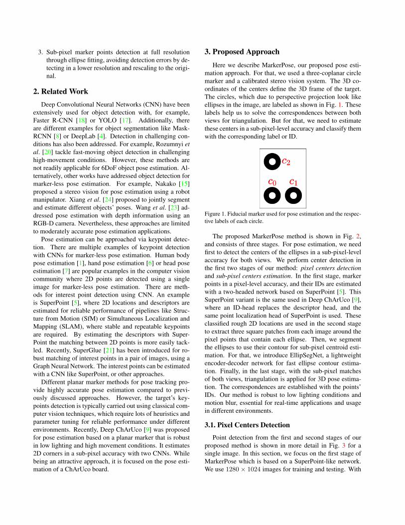
3. Proposed Approach
Here we describe MarkerPose, our proposed pose esti-
mation approach. For that, we used a three-coplanar circle
marker and a calibrated stereo vision system. The 3D co-
ordinates of the centers define the 3D frame of the target.
The circles, which due to perspective projection look like
ellipses in the image, are labeled as shown in Fig. 1. These
labels help us to solve the correspondences between both
views for triangulation. But for that, we need to estimate
these centers in a sub-pixel-level accuracy and classify them
with the corresponding label or ID.
Figure 1. Fiducial marker used for pose estimation and the respec-
tive labels of each circle.
The proposed MarkerPose method is shown in Fig. 2,
and consists of three stages. For pose estimation, we need
first to detect the centers of the ellipses in a sub-pixel-level
accuracy for both views. We perform center detection in
the first two stages of our method: pixel centers detection
and sub-pixel centers estimation. In the first stage, marker
points in a pixel-level accuracy, and their IDs are estimated
with a two-headed network based on SuperPoint [5]. This
SuperPoint variant is the same used in Deep ChArUco [9],
where an ID-head replaces the descriptor head, and the
same point localization head of SuperPoint is used. These
classified rough 2D locations are used in the second stage
to extract three square patches from each image around the
pixel points that contain each ellipse. Then, we segment
the ellipses to use their contour for sub-pixel centroid esti-
mation. For that, we introduce EllipSegNet, a lightweight
encoder-decoder network for fast ellipse contour estima-
tion. Finally, in the last stage, with the sub-pixel matches
of both views, triangulation is applied for 3D pose estima-
tion. The correspondences are established with the points’
IDs. Our method is robust to low lighting conditions and
motion blur, essential for real-time applications and usage
in different environments.
3.1. Pixel Centers Detection
Point detection from the first and second stages of our
proposed method is shown in more detail in Fig. 3 for a
single image. In this section, we focus on the first stage of
MarkerPose which is based on a SuperPoint-like network.
We use 1280 × 1024 images for training and testing. With

Figure 2. MarkerPose: the proposed approach for marker-based pose estimation, which consists of three stages. The first and second stage
is for sub-pixel centers estimation, and the last stage for triangulation and target pose estimation.
the SuperPoint-like network, 2D pixel-level accuracy center
detection is performed at a lower resolution of 320 × 240.
For that, the input 1280× 1024 images are resized to 320×240. The estimated rough 2D locations are then scaled-back
to full resolution.
The original SuperPoint network [5] consists of a back-
bone and two heads: a head for point localization and an-
other for point descriptors. Instead of the descriptors head,
an ID-head is used for point classification as shown Fig. 3.
The backbone is a shared encoder for both branches, which
reduces the dimensionality of an image W×H to a factor of
eight W/8×H/8, using eight convolution layers and three
2× 2 max-pooling layers after every two convolutions. The
point localization head produces a W/8×H/8× 65 tensor,
which is a pixel location distribution of each 8×8 region of
the input image and an additional channel for background or
non-point locations. The ID head produces a W/8×H/8×4tensor, which is a classification distribution for each 8×8 re-
gion of the input image, where we have three labels for each
center (see Fig. 1) and an additional label for background or
non-center pixels. In this way, we have the following labels:
0 for c0, 1 for c1, 2 for c2, and 3 for background. With the
estimated IDs, we sort the resulting array of 2D points from
0 to 2 labels, where the first row corresponds to the c0 point,
and so on. With the output from this network, we solve the
correspondence problem between both views.
The loss for this stage is the sum of the center location
loss Lloc, and the ID classification loss Lid,
L(P,P, C,C) = λ1Lloc(P,P) + λ2Lid(C,C) , (1)
where P is the predicted W/8×H/8×65 location tensor by
the network, and P is the ground truth. C is the predicted
W/8×H/8×4 classification tensor, and C the ground truth.
For both Lloc and Lid cross-entropy loss is used.
3.2. Subpixel Centers Estimation
Once the circle center locations have been detected at a
pixel-level resolution, in this second stage we refine these
points to a sub-pixel-level accuracy for triangulation and
accurate pose estimation. With the scaled-back pixel-level
points from the SuperPoint-like network to the original res-
olution, we extract 120× 120 patches around each detected
center from the original 1280 × 1024 image. The ellipse is
supposed within those patches for sub-pixel center estima-
tion.
Since circles project as ellipses onto the image plane,
we propose a lightweight encoder-decoder network called
EllipSegNet for segmenting the extracted ellipse patches
for contour estimation and sub-pixel centroid calculation
as shown Fig. 3. EllipSegNet is meant for real-time appli-
cations, and its weight is just 1.1 MB, and a forward pass
takes 2.3 ms approximately with an NVIDIA Tesla P100.
The encoder of the network consists of eight 3 × 3 convo-
lution layers with 16-16-32-32-64-64-64-64 channels, re-
spectively. From the second convolution layer, three 2 × 2max pool layers are used between each pair of convolutional
layers. The decoder part of EllipSegNet consists of bilinear
upsampling with a factor of 2 and skip connections via con-
catenation followed by two convolution operations. There
are a total of six 3×3 convolution layers with 64-32-32-16-
16-16 channels, respectively. Finally, a 1 × 1 convolution
layer is used to map the 16 channels to 1 for binary segmen-
tation.
The binary cross-entropy loss is used in this stage for the
training of the network,
L(Y, Y) = −
∑
i
∑
j
yij log p(yij)+(1−yij) log[1−p(yij)] ,
(2)
where Y is the predicted mask, and Y the ground truth.
Furthermore, p is the sigmoid function,
p(x) =1
1 + e−x. (3)
For sub-pixel point estimation, we can compute the
centroid of the white pixels of the mask with OpenCV’s
moments function, or we can use the contour of the ellipse
to fit an ellipse with the OpenCV fitEllipse function.
Either way, the detected center coordinates are estimated

Figure 3. Sub-pixel centers detection for a single image.
at sub-pixel accuracy. We adopt using fitEllipse, be-
cause we obtain more robust and accurate results than the
other approach.
For sub-pixel estimation, the ellipse can be partially in-
side of the 120×120 patch. When there is more than one el-
lipse within the patch, the nearest to the image center is seg-
mented. Although ellipse contour estimation is performed
pixel-wise (discrete way), the sub-pixel calculation is not
discrete, i.e., the estimation is not restricted to a discrete
grid of positions, which enables higher accuracy. Further-
more, this sub-pixel estimation is carried out at full resolu-
tion, which leads to highly accurate pose estimation results
because if we perform sub-pixel detection in a lower reso-
lution, we need to scale-back the points to the original size.
In this process, the small detection error in the lower reso-
lution can be also scaled, and incur pose estimation errors.
For example, a sub-pixel detection error less than a pixel at
320×240 can become larger than a pixel after scaling-back
to the original resolution of 1280× 1024. Therefore, an er-
ror in low resolution can increase in the original resolution
and this is critical in final pose estimation for high-accuracy
applications.
3.3. Marker Pose Estimation
In the two previous sections, we described the sub-pixel
2D location estimation of the target’s centers for a single
image. This section describes the last stage of MarkerPose
which consists of estimating the pose of the marker. This
work is focused on pose estimation with a stereo vision sys-
tem. With the estimated IDs, we solve the point correspon-
dence problem. Hence, with the calibrated stereo vision
system and the correspondences x1 ↔ x2, we can recover
the 3D position of the points. Following the camera pinhole
model, the projection of a 3D point X in both image planes
can be written as,
x1 = P1X , x2 = P2X , (4)
where P1 and P2 are the projection matrices for the cam-
eras, estimated through calibration. To solve for X, the ho-
mogeneous solution is given by
x1p3T
1− p1T
1
y1p3T
1− p2T
1
x2p3T
2− p1T
2
y2p3T
2− p2T
2
X = 0 , (5)
where pi1
and pi2
represent the i-th row of P1 and P2
respectively, as column vectors. We solve this with the
OpenCV’s triangulate function.
With the three 3D points of the target, we can define a
3D coordinate system. For that, we define the c0 center as
the origin of the target frame. The 3D position of this point
gives us the translation vector t of the target frame with
respect to the cameras. Furthermore, the circles c1 and c2represent the direction of the x-axis and y-axis of the target
coordinate system, respectively. The unit vector x of the
marker frame can be estimated with c0 and c1 3D centers.
Similarly, the unit vector y with c0 and c2 3D coordinates.
Using cross product, the unit vector of the z-axis, that is
perpendicular to the target, is calculated z = x× y. Finally,
the rotation matrix of the target frame relative to the stereo
vision system is R = [x y z]. In this way, we track the
position t and orientation R of the target coordinate system.
For accurate triangulation results, we compensate the 2D
sub-pixel points for lens distortion before triangulation.
3.4. Detection Method with a Classical Approach
We also developed a center detection strategy using clas-
sical computer vision techniques. This method was de-
signed to aid the labeling of training data and for compari-
son with the proposed approach using convolutional neural
networks. This classical approach consists of binarizing and
determining the image contours. As the outer black circle
and internal white circles are concentric, their centers must
have approximately the same image coordinates. We ex-
ploit this criterion to estimate the contour of the black circle
and its center. This approach provides highly accurate re-
sults, but it is not robust. We need controlled environments
for successful detection results. Furthermore, it requires pa-
rameter tuning to make it work in different environments
and lighting conditions. Finally, as our stereo vision system
is calibrated, we exploit epipolar constraints for solving the

matching problem of points for pair of images, required for
pose estimation.
4. Implementation Details
This section explains the details about the datasets, train-
ing of the SuperPoint-like and EllipSegNet networks, and
the experimental setup.
4.1. Training Dataset
We acquired a total of 5683 grayscale images with a
1280 × 1024 resolution. There are multiple positions and
orientations of the target in our dataset, and the images were
acquired at different lighting conditions. Furthermore, we
also used two different target dimensions. Two example
images are shown in Fig. 4. For training the first stage of
MarkerPose with the SuperPoint-like network, these images
were resized to 320 × 240. For supervision, the center es-
timation was performed using the classical approach intro-
duced in Section 3.4. For data augmentation, we randomly
applied the following operations: vertical and horizontal
flip, random affine transformations, contrast modifications,
motion blur, Gaussian blur, and Gaussian noise.
Figure 4. Example of training images for the SuperPoint-like net-
work.
For EllipSegNet training, we extract 120 × 120 patches
from some of the images used for training the SuperPoin-
like network, resulting in 11010 patches. Fig. 5 shows some
patch examples, where there are images where a single el-
lipse is in the patch and cases where we have more than
one ellipse. We applied the same data augmentation trans-
formations as described above for the keypoints detection
network to ensure the robustness of the entire pipeline.
Figure 5. Example of training images for EllipSegNet.
4.2. Models Training
We implemented the point detection and ellipse segmen-
tation networks with PyTorch. A version was implemented
with Python and another with C++ using LibTorch. For the
SuperPoint-like network and the lightweight EllipSegNet,
we used the Adam optimizer with a learning rate of 0.0001.
4.3. Stereo Vision Setup
The experimental stereo vision setup consisted of
two monochromatic Basler cameras acA1300-200um
(1280x1024, 203 fps), and two lenses Edmund Optics
58001 (12 mm fixed focal length). We calibrated our stereo
vision system with OpenCV and a pattern of asymmetric
circles. A total of 21 different poses of the pattern were
acquired for calibration. We obtained a mean reprojection
error of 0.1230 px and 0.1284 px for the first and second
views, respectively. These errors are small and appropriate
for accurate pose estimation.
5. Experiments
For validation, we compared MarkerPose with the classi-
cal approach discussed in Section 3.4. For the experiments
presented in this section, the distance between c0 and c1centers of the target is 25 mm, and the distance between c0and c2 centers is 40 mm.
5.1. Validation Experiments with a Robotic Arm
We evaluated the proposed pose estimation system with
two experiments using an EPSON C3 robot (0.02 mm of
precision). The robot was used for assessing the tracking
accuracy. We attached the target to the arm’s end effector,
and we evaluated the displacement and rotation of the target
moved by the robot.
5.1.1 Displacement Evaluation
For this experiment, the end effector was displaced a fixed
distance of ∆x = 10 mm in a total of 20 positions. We mea-
sured the distance between consecutive frames, which give
us 19 displacement estimations of each center of the target,
i.e., a total of 57 displacement measurements. Fig. 6 shows
an example of the first 10 frames used for this experiment,
acquired with the left camera (first view).
Fig. 7 shows the results of the estimated relative dis-
tance between the 19 pairs of consecutive frames with
MarkerPose and the classical approach. The measurements
can be compared with the reference displacement line of
10 mm. Our proposed approach achieves high-accuracy re-
sults compared to the classical method.
We also estimated the mean absolute error (MAE), the
RMS error, and the (maximum error) infinity norm ℓ∞ of
the errors of the calculated 57 distances of all centers, using

Figure 6. First 10 frames of the sequence for distance evaluation.
A total of 20 positions were captured.
Figure 7. Displacement results from the 19 pairs of frames of
MarkerPose and the classical method.
both methods. The results are reported in Table 1, where
the results of MarkerPose with MAE and RMS metrics are
comparable to the classical method. The maximum error
is slightly larger with our approach, but a maximum error
of 0.1164 mm is low enough for pose estimation in high
precision applications.
Method MAE (mm) RMS (mm) ℓ∞ (mm)
MarkerPose 0.0461 0.0544 0.1164
Classical 0.0446 0.0508 0.1086Table 1. Displacement experiment: performance metrics for the 57
distance measurements.
Finally, we report the same metrics for the 3D distances
between the centers estimated with the triangulated points.
In this case, we have 20 measurements from the 20 acquired
frames. These were obtained as the distance d(c0, c1) be-
tween c0 and c1 centers and the distance d(c0, c2) between
c0 and c2 points, where d(.) is the Euclidean distance be-
tween two 3D points. Table 2 shows the results. Marker-
Pose provides an overall better performance than the classi-
cal approach in this case.
MarkerPose Classical method
d(c0, c1) d(c0, c2) d(c0, c1) d(c0, c2)MAE (mm) 0.1315 0.2976 0.1558 0.3435
RMS (mm) 0.1326 0.2982 0.1569 0.3448
ℓ∞ (mm) 0.1692 0.3257 0.1833 0.4107
Table 2. Displacement experiment: metrics of the distance be-
tween the centers c0 and c1, and the centers c0 and c2, using the
frames acquired for displacement estimation. Here, d(.) is the Eu-
clidean distance between two 3D points.
5.1.2 Rotation Evaluation
The reference was established by rotating the robot’s end
effector at a fixed angle of ∆θ = 5◦ in a sequence of 7
frames. We measured the angle between pairs of consecu-
tive frames, which gives us 6 rotation estimations. The cal-
culation of the rotation angle between frames is performed
with the following expression,
θ = arccos
[
Tr(R12)− 1
2
]
, (6)
where R12 is the rotation matrix between the first and sec-
ond frame, and can be estimated as R12 = RT
1R2. That is,
R12 is the rotation matrix of the target coordinate system
between frame 1 and frame 2. The entire sequence captured
by the left camera is shown in Fig. 8.
Figure 8. Entire sequence of 7 frames from the left camera for
angle estimation.
The estimated relative angle between pairs of frames is
shown in Fig. 9 for MarkerPose and the classical method.
By comparing with the reference line of 5◦, the proposed
approach achieves better results than the classical approach
with less dispersion. Furthermore, the metrics in Table 3
show the same behavior, where the MAE, RMS error,
and the ℓ∞ norm are significantly lower with MarkerPose.
These results show the potential of our approach for highly
accurate pose estimation applications.
Figure 9. Rotation angle measurement results of MarkerPose and
the classical method. A total of 6 pairs of consecutive frames were
used.
Similarly to the displacement experiment, the 3D Eu-
clidean distance between centers is reported in Table 4,
where using the seven frames acquired, the distance be-
tween c0 and c1 centers and the distance between c0 and
c2 centers, are estimated and the same metrics are used for

Figure 10. Results of our center point detection method for synthetically applied motion blur and lighting changes to a test input image.
Method MAE RMS ℓ∞MarkerPose 0.0322° 0.0413° 0.0687°
Classical 0.1107° 0.1290° 0.2317°Table 3. Rotation experiment: angle metrics evaluation of the six
pairs of frames.
these estimations. The metrics between the c0 and c2 cen-
ters are better with our proposed method. For the metrics
between c0 and c1, the classical method is better except for
maximum error.
MarkerPose Classical method
d(c0, c1) d(c0, c2) d(c0, c1) d(c0, c2)MAE (mm) 0.1537 0.2639 0.1315 0.3001
RMS (mm) 0.1548 0.2642 0.1416 0.3011
ℓ∞ (mm) 0.1896 0.2867 0.2150 0.3387
Table 4. Rotation experiment: metrics of the distance between the
centers c0 and c1, and the centers c0 and c2, using the frames ac-
quired for angle estimation.
5.2. Evaluation with Synthetic Effects
We evaluated the proposed method under low lighting
conditions and motion blur. The transformations were ap-
plied synthetically to the image, and the results are shown in
Fig. 10. For motion blur, six different kernels sizes were ap-
plied to the original image, and center detection was carried
out. Synthetic darkness was applied by scaling the original
image with a factor α. These α values range from 0.25 to
0.039. Those results show the robustness of our point de-
tection method.
The distance estimation experiment was carried out
again using the same dataset for different lighting changes
with α values ranging from 0.5 to 0.0625. An α value of 1
does not represent a lighting change. The results are re-
ported in Table 5. These results show the robustness of
MarkerPose to low lighting conditions, where even for the
darkest case (α = 0.0625) we obtain highly accurate re-
sults.
α MAE (mm) RMS (mm) ℓ∞1 0.0461 0.0544 0.1164
0.5 0.0451 0.0539 0.1352
0.25 0.0476 0.0557 0.1404
0.125 0.0528 0.0603 0.1313
0.0625 0.0568 0.0723 0.2130Table 5. Performance metrics for the distance estimation results for
different lighting scaling values α from 0.5 to 0.0625. For α = 1there are no changes in the images.
5.3. Pose Estimation for a 3D Freehand UltrasoundSystem
To showcase the highly accurate pose estimation result
from MarkerPose, we describe an experiment with the 3D
freehand ultrasound (US) technique [10]. It consists of
tracking the pose of a US probe while simultaneously ac-
quiring US images. This procedure allows for mapping the
2D US scans to a volume by using a predefined transforma-
tion obtained via calibration [14].
For this experiment, we used the same stereo vision setup
and the US machine Biocare iS20. To evaluate our proposed
pose estimation method, we reconstructed and estimated
a cylinder’s diameter with the US images. This cylinder
was submerged in water for ultrasound visualization into
another cylindrical object for easy acquisition. An exam-
ple of stereo and US images during acquisition is shown in
Fig. 11, where the measured object is inside.
Figure 11. Example of 3D freehand ultrasound acquisition with
the estimated pose with the MarkerPose method. The acquired
ultrasound image shows a ring-like structure corresponding to the
measured cylinder object.

For this experiment, 94 ultrasound images were ac-
quired along the central axis of the cylinder. We semi-
automatically segmented the images for 3D reconstruction.
The reconstruction results with our pose estimation method
are shown in Fig. 12, which is in agreement with the ref-
erence shape. Moreover, with this point cloud, we esti-
mated the cylinder’s outer diameter through least squares.
For that, we use the outer points of the 3D coordinates. The
estimated diameter with the point cloud was 15.999 mm,
whereas the cylinder’s diameter measured with a caliper
was 15.82 mm. This result corresponds to an absolute er-
ror of 0.18 mm, which shows the method’s suitability for
highly accurate pose estimation applications.
Figure 12. 3D reconstruction results of the measured cylinder ob-
ject with the 3D freehand ultrasound technique and the proposed
pose estimation method. 94 2D ultrasound slices were used for 3D
reconstruction.
5.4. Runtime Evaluation
We measured execution time for both of our point de-
tection stages independently and for the entire MarkerPose
pipeline. We use an NVIDIA Tesla P100 in a cloud com-
puting platform in Python for runtime evaluation. Our first
stage with the SuperPoint-like network takes 2.7 ms approx-
imately for a single 320×240 image. A forward pass in the
second stage with the EllipSegNet runs in 2.3 ms approxi-
mately for a single 120×120 array. Our entire pose estima-
tion method, for two input 1280 × 1024 images, including
2D points undistortion in both views, triangulation, and fi-
nally rotation matrix and translation vector estimation, runs
at around 62 FPS. These results show the suitability of our
proposed approach for real-time applications.
The same experiments were carried out with a GPU
NIVIDA GTX 960M on a laptop using Python. A for-
ward pass with the SuperPoint-like network runs at about
32.6 ms. A forward pass with the EllipSegNet takes 6.1 ms
approximately. The entire pose estimation pipeline runs on
average at 12 FPS. These results show that our method can
achieve real-time performance even in an environment with
fewer computational resources.
6. Conclusions
The need for highly accurate pose estimation is linked
to applications that require reliable object tracking, like in
the case of freehand ultrasound and other computer vision-
based navigation and guidance systems. In most cases, the
use of infrared or electromagnetic tracking devices leads
to expensive systems which are not routinely used. Here,
we have proposed MarkerPose: a real-time, highly accurate
pose estimation method based on stereo triangulation using
a planar marker detected with a deep neural network ap-
proach. Our multi-stage detection architecture leads to fast
marker keypoint ID identification and sub-pixel keypoint
detection at full image resolution by exploiting ellipse fit-
ting using EllipSegNet, an introduced lightweight network.
We showed the potential of the proposed method for accu-
rate pose estimation and tracking under different lighting
and motion blur conditions, and with a biomedical appli-
cation. Future work involves designing novel markers that
further exploit the capabilities of the proposed method.
Acknowledgement
This work has been partly funded by Universidad Tecno-
logica de Bolivar project C2018P005 and Minciencias con-
tract 935-2019. J. Meza thanks Universidad Tecnologica de
Bolivar for a post-graduate scholarship and MinCiencias,
and MinSalud for a “Joven Talento” scholarship.
References
[1] Mykhaylo Andriluka, Umar Iqbal, Eldar Insafutdinov,
Leonid Pishchulin, Anton Milan, Juergen Gall, and Bernt
Schiele. Posetrack: A benchmark for human pose estima-
tion and tracking. In Proceedings of the IEEE conference on
computer vision and pattern recognition, pages 5167–5176,
2018.
[2] Ehsan Basafa, Pezhman Foroughi, Martin Hossbach, Jas-
mine Bhanushali, and Philipp Stolka. Visual tracking for
multi-modality computer-assisted image guidance. In Med-
ical Imaging 2017: Image-Guided Procedures, Robotic In-
terventions, and Modeling, volume 10135, page 101352S.
International Society for Optics and Photonics, 2017.
[3] Alisa JV Brown, Ali Uneri, Tharindu S De Silva, Amir Man-
bachi, and Jeffrey H Siewerdsen. Design and validation of

an open-source library of dynamic reference frames for re-
search and education in optical tracking. Journal of Medical
Imaging, 5(2):021215, 2018.
[4] Liang-Chieh Chen, George Papandreou, Iasonas Kokkinos,
Kevin Murphy, and Alan L Yuille. Deeplab: Semantic image
segmentation with deep convolutional nets, atrous convolu-
tion, and fully connected crfs. IEEE transactions on pattern
analysis and machine intelligence, 40(4):834–848, 2017.
[5] Daniel DeTone, Tomasz Malisiewicz, and Andrew Rabi-
novich. Superpoint: Self-supervised interest point detection
and description. In Proceedings of the IEEE conference on
computer vision and pattern recognition workshops, pages
224–236, 2018.
[6] Liuhao Ge, Zhou Ren, Yuncheng Li, Zehao Xue, Yingying
Wang, Jianfei Cai, and Junsong Yuan. 3d hand shape and
pose estimation from a single rgb image. In Proceedings of
the IEEE/CVF Conference on Computer Vision and Pattern
Recognition, pages 10833–10842, 2019.
[7] Aryaman Gupta, Kalpit Thakkar, Vineet Gandhi, and PJ
Narayanan. Nose, eyes and ears: Head pose estimation by
locating facial keypoints. In ICASSP 2019-2019 IEEE Inter-
national Conference on Acoustics, Speech and Signal Pro-
cessing (ICASSP), pages 1977–1981. IEEE, 2019.
[8] Kaiming He, Georgia Gkioxari, Piotr Dollar, and Ross Gir-
shick. Mask r-cnn. In Proceedings of the IEEE international
conference on computer vision, pages 2961–2969, 2017.
[9] Danying Hu, Daniel DeTone, and Tomasz Malisiewicz. Deep
charuco: Dark charuco marker pose estimation. In Proceed-
ings of the IEEE/CVF Conference on Computer Vision and
Pattern Recognition, pages 8436–8444, 2019.
[10] Qinghua Huang and Zhaozheng Zeng. A Review on Real-
Time 3D Ultrasound Imaging Technology. BioMed research
international, 2017:6027029, 2017.
[11] Ho Chuen Kam, Ying Kin Yu, and Kin Hong Wong. An im-
provement on aruco marker for pose tracking using kalman
filter. In 2018 19th IEEE/ACIS International Conference
on Software Engineering, Artificial Intelligence, Networking
and Parallel/Distributed Computing (SNPD), pages 65–69.
IEEE, 2018.
[12] Jisung Kim, Youngdo Jeong, Hyojin Lee, and Hongsik Yun.
Marker-based structural displacement measurement models
with camera movement error correction using image match-
ing and anomaly detection. Sensors, 20(19):5676, 2020.
[13] Ji Yang Lee and Cheol-soo Lee. Path planning for scara robot
based on marker detection using feature extraction and, la-
belling. International Journal of Computer Integrated Man-
ufacturing, 31(8):769–776, 2018.
[14] Jhacson Meza, Pedro Simarra, Sara Contreras-Ojeda,
Lenny A Romero, Sonia H Contreras-Ortiz, Fer-
nando Arambula Cosıo, and Andres G Marrugo. A
low-cost multi-modal medical imaging system with fringe
projection profilometry and 3d freehand ultrasound. Proc.
SPIE, 11330:1133004, 2020.
[15] Yoshihiro Nakano. Stereo vision based single-shot 6d ob-
ject pose estimation for bin-picking by a robot manipulator.
arXiv preprint arXiv:2005.13759, 2020.
[16] Tanmay Nath, Alexander Mathis, An Chi Chen, Amir Patel,
Matthias Bethge, and Mackenzie Weygandt Mathis. Using
deeplabcut for 3d markerless pose estimation across species
and behaviors. Nature protocols, 14(7):2152–2176, 2019.
[17] Joseph Redmon, Santosh Divvala, Ross Girshick, and Ali
Farhadi. You only look once: Unified, real-time object de-
tection. In Proceedings of the IEEE conference on computer
vision and pattern recognition, pages 779–788, 2016.
[18] Shaoqing Ren, Kaiming He, Ross Girshick, and Jian Sun.
Faster r-cnn: towards real-time object detection with region
proposal networks. IEEE transactions on pattern analysis
and machine intelligence, 39(6):1137–1149, 2016.
[19] C Romero, C Naufal, J Meza, and Andres G Marrugo. A vali-
dation strategy for a target-based vision tracking system with
an industrial robot. J. Phys.: Conf. Series, 1547(1):012018–
8, 2020.
[20] Denys Rozumnyi, Jiri Matas, Filip Sroubek, Marc Pollefeys,
and Martin R Oswald. Fmodetect: Robust detection and
trajectory estimation of fast moving objects. arXiv preprint
arXiv:2012.08216, 2020.
[21] Paul-Edouard Sarlin, Daniel DeTone, Tomasz Malisiewicz,
and Andrew Rabinovich. Superglue: Learning feature
matching with graph neural networks. In Proceedings of
the IEEE/CVF conference on computer vision and pattern
recognition, pages 4938–4947, 2020.
[22] Yongbin Sun, Yimin Deng, Haibin Duan, and Xiaobin Xu.
Bionic visual close-range navigation control system for the
docking stage of probe-and-drogue autonomous aerial re-
fueling. Aerospace Science and Technology, 91:136–149,
2019.
[23] He Wang, Srinath Sridhar, Jingwei Huang, Julien Valentin,
Shuran Song, and Leonidas J Guibas. Normalized object
coordinate space for category-level 6d object pose and size
estimation. In Proceedings of the IEEE/CVF Conference
on Computer Vision and Pattern Recognition, pages 2642–
2651, 2019.
[24] Yu Xiang, Tanner Schmidt, Venkatraman Narayanan, and
Dieter Fox. Posecnn: A convolutional neural network for
6d object pose estimation in cluttered scenes. arXiv preprint
arXiv:1711.00199, 2017.
