Embed Size (px)
Citation preview

Manufacturing and Characterization of Chitin Nanowhisker/Polyolefin Nanocomposites
by
Sharon Chi-Yan Li
A thesis submitted in conformity with the requirements for the degree of Master of Applied Science
Graduate Department of Mechanical and Industrial Engineering University of Toronto
©Copyright by Sharon Chi-Yan Li 2016
ii
Manufacturing and Characterization of Chitin
Nanowhisker/Polyolefin Nanocomposites
Sharon Chi-Yan Li
Master of Applied Science
Graduate Department of Mechanical and Industrial Engineering University of Toronto
2016
Abstract
This thesis discusses the potential large scale production of polymer nanocomposites using
polypropylene and high density polyethylene with chitin nanowhiskers (CNW). Fabrication of
the nanocomposites with and without compatibilization were prepared over a range of CNW
loading through melt compounding. The processing techniques tested included direct melt
compounding, and a two step masterbatch dilution process. Three studies were investigated to
build an understanding of the composite structure-property relationship based on morphological,
thermal, water barrier, mechanical, and rheological properties. The addition of CNW and
compatibilizer provided mechanical reinforcement and improvements in water barrier. However,
the CNW significantly affected the crystallinities of the composites, which impacted its overall
properties. Finally, the masterbatch diluted composites maintained good mechanical and water
barrier compared to the neat polymer, but the directly compounded composites were still better.
Therefore, further optimization of this process is required to maximize CNW dispersion, which
also greatly affected the composite properties.

iii
Acknowledgments First and foremost, I would like to express my gratitude and appreciation to my supervisor
Professor Hani Naguib for his continuous encouragement and guidance for the past two years.
This research would not have been possible without his never ending support, which had also
provided me with opportunities to strengthen and develop new skills as a researcher.
I would like to thank all my colleagues in SAPL including Dr. Reza Rizvi, Dr. Shahrzad
Ghaffari, Gary Sun, Harvey Shi, Nazanin Khalili, Dr. Eunji In, Mohamed Kshad, Farooq Al
Jahwari, Muhammad Anwer, Carlton Hoy, Kyle Eastwood, Janice Song, Ali Anwer, Anastasia
Wickeler, Sean Lin, Sherif Ramadan, Adam Pearson, and Arturo Reza Ugalde for providing
moral support, suggestions, and friendly help in the lab that has kept me driven to work every
day. I would also like to acknowledge my undergraduate thesis student, Ziwei Su, for his
contributions to this research. Special thanks goes out to Yasamin Kazemi, Adel Ramezani
Kakroodi, Fatemeh Mortazavi Alavi, and Pei-Yu Kuo whom have voluntarily reached out at
some point to help me with my research. I would also like to thank all my friends who have
constantly kept me grounded despite all the late nights and tough times.
I would like to acknowledge Natural Science and Engineering Research Council of Canada
(NSERC), Canada Research Chairs (CRC), Ontario Centers of Excellence (OCE), and BOCO
Technology Inc. for providing financial support. I would also like to thank Aaron Guan from
BOCO Technology Inc. for his time commitment in research meetings and supplying the
materials used in this research.
Finally, I would like to thank my family, my parents Peggy and Bernard, and my sister Rophina
for many years of unconditional support and assistance that has led me to where I am today.

iv
Table of Contents
Acknowledgments ........................................................................................................................ iii
Table of Contents ......................................................................................................................... iv
List of Tables ............................................................................................................................... vii
List of Figures ............................................................................................................................. viii
List of Abbreviations .....................................................................................................................x
Chapter 1 Introduction ............................................................................................................1
1.1 Preamble ..............................................................................................................................1
1.2 Research Objectives and Contributions ...............................................................................1
1.3 Thesis Organization .............................................................................................................2
Chapter 2 Background and Literature Survey .....................................................................3
2.1 Polymer Composite Packaging ............................................................................................3
2.2 Chitin Nanowhiskers ............................................................................................................3
2.3 Processing and Properties of Polymer Composites with Bio-Fillers ...................................4
2.4 Water Vapor Barrier Properties of Polymer Composites ....................................................6
2.5 Polypropylene Composites ..................................................................................................7
2.6 High Density Polyethylene Composites ..............................................................................8
2.6.1 Effects of Crystallinity on the Properties of HDPE .................................................8
2.6.2 Effects of Fillers on the Crystallinity and Properties of HDPE ...............................9
2.6.3 Effects of Filler Dimensionality and Orientation on Crystallinity of HDPE .........10
2.7 Masterbatch Dilution of Polymer Composites ...................................................................10
2.8 Summary ............................................................................................................................12
Chapter 3 Chitin Nanowhisker/Polypropylene Composites ..............................................13
3.1 Materials and Methods for Fabrication of CNW/PP Composites ......................................13

v
3.1.1 Materials for CNW/PP Composite Fabrication .....................................................13
3.1.2 Fabrication of CNW/PP Composites .....................................................................13
3.1.3 Characterization of CNW/PP Composites .............................................................14
3.2 Results and Discussion of CNW/PP Composites ..............................................................16
3.2.1 Morphology of CNW and CNW/PP Composites ..................................................16
3.2.2 Thermal Properties of CNW/PP Composites .........................................................18
3.2.3 Water Vapor Barrier Properties of CNW/PP Composites .....................................22
3.2.4 Mechanical Properties of CNW/PP Composites....................................................26
3.2.5 Rheological Properties of CNW/PP Composites ...................................................29
3.3 Summary ............................................................................................................................31
Chapter 4 Chitin Nanowhisker/High Density Polyethylene Composites ..........................32
4.1 Materials and Methods for Fabrication of CNW/HDPE Composites ................................32
4.1.1 Materials for CNW/HDPE Composite Fabrication ...............................................32
4.1.2 Fabrication of CNW/HDPE Composites ...............................................................32
4.1.3 Characterization of CNW/HDPE Composites .......................................................33
4.2 Results and Discussion of CNW/HDPE Composites ........................................................34
4.2.1 SEM and AFM of CNW/HDPE Composites .........................................................34
4.2.2 TGA and DSC of CNW/HDPE Composites ..........................................................36
4.2.3 Water Vapor Transmission Test of CNW/HDPE Composites ..............................39
4.2.4 Tensile Test of CNW/HDPE Composites ..............................................................42
4.2.5 Rheology Test of CNW/HDPE Composites ..........................................................45
4.3 Summary ............................................................................................................................48
Chapter 5 Chitin Nanowhisker/Polyolefin Composite Masterbatches .............................50
5.1 Materials and Methods for Fabrication of Masterbatch and Diluted CNW/PP and CNW/HDPE Composites ...................................................................................................50
5.1.1 Materials for Fabrication of CNW/PP and CNW/HDPE Composites ...................50

vi
5.1.2 Preparation of Masterbatch and Dilution of CNW/PP and CNW/HDPE Composites .............................................................................................................50
5.1.3 Characterization of Masterbatch and Diluted CNW/PP and CNW/HDPE Composites .............................................................................................................51
5.2 Results and Discussion of Masterbatch and Diluted CNW/PP and CNW/HDPE Composites .........................................................................................................................52
5.2.1 SEM Morphology of Masterbatch and Diluted CNW/PP and CNW/HDPE Composites .............................................................................................................52
5.2.2 TGA and DSC of Diluted CNW/PP and CNW/HDPE Composites ......................54
5.2.3 Water Barrier Properties of Diluted CNW/PP and CNW/HDPE Composites ......58
5.2.4 Tensile Testing of Diluted CNW/PP and CNW/HDPE Composites .....................60
5.2.5 Rheology of Diluted CNW/PP and CNW/HDPE Composites ..............................65
5.3 Summary ............................................................................................................................68
Chapter 6 Conclusions and Future Work ............................................................................69
6.1 Conclusions ........................................................................................................................69
6.2 Future Work .......................................................................................................................70
References .................................................................................................................................... 71

vii
List of Tables Table 3-1 Thermal properties extracted from TGA and DSC curves. .......................................... 21
Table 4-1 Thermal properties of all the compositions obtained from the TGA and DSC curves. 38
Table 5-1 Thermal properties extracted from the TGA and DSC curves. .................................... 56
viii
List of Figures Figure 2-1 Chemical structure of chitin. ......................................................................................... 4
Figure 3-1 Schematic of melt compounding (a), compression molding (b), and injection molding
(c) processing methods. ................................................................................................................ 14
Figure 3-2 AFM (a) and SEM (b) images of the morphology of dried CNWs. ........................... 16
Figure 3-3 AFM images of the cross sections of neat PP (a), 2% (b), 5% (c), and 10% (d)
CNW/MAPP, and SEM images of the cross sections of 2% (e), 5% (f), and 10% (g)
CNW/MAPP, and 10% CNW/PP. ................................................................................................ 17
Figure 3-4 TGA curves for CNW/PP composites (a) and CNW/MAPP composites (b), and heat-
cool DSC curves for CNW/PP composites (c) and CNW/MAPP composites (d). ....................... 21
Figure 3-5 Weight change vs. time curves of CNW/PP (a) and CNW/MAPP (b) composites, and
water vapor permeance vs. CNW loading of CNW/PP and CNW/MAPP composites (c). .......... 24
Figure 3-6 Elastic modulus (a), ultimate tensile strength (b), and elongation strain at break (c) of
CNW/PP and CNW/MAPP composites at 1, 2, 5, and 10 wt% CNW loading. ........................... 27
Figure 3-7 Extensional viscosity vs. elongation time curves of CNW/PP (a) and CNW/MAPP (b)
composites. .................................................................................................................................... 30
Figure 4-1 AFM and SEM images of the cross sections of neat HDPE (a), 2% CNW/MAPE (b
and e), 5% CNW/MAPE (c and f), 10% CNW/MAPE (d and g), and 10% CNW/HDPE (h). .... 35
Figure 4-2 TGA curves for CNW/HDPE composites (a) and CNW/MAPE composites (b), and
heat-cool DSC curves for CNW/HDPE composites (c) and CNW/MAPE composites (d). ........ 38
Figure 4-3 Weight change vs. time curves of CNW/HDPE (a) and CNW/MAPE (b) composites,
and WVP vs. CNW loading of CNW/HDPE and CNW/MAPE composites. .............................. 41
Figure 4-4 Tensile properties of the CNW/HDPE and CNW/MAPE composites based on elastic
modulus (a), ultimate tensile strength (b), and elongation strain at break (c). ............................. 44

ix
Figure 4-5 Storage modulus and complex viscosity of CNW/HDPE (a and c) and CNW/MAPE
(b and d) composites with respect to frequency. ........................................................................... 47
Figure 5-1 SEM images of 10% CNW/MAPP (a), 2% diluted CNW/MAPP (b and c), 10%
CNW/HDPE (d), and 2% diluted CNW/MAPE (e and f) composites. ......................................... 53
Figure 5-2 TGA curves for CNW/PP composites (a) and CNW/MAPP composites (b), and heat-
cool DSC curves for CNW/PP composites (c) and CNW/MAPP composites (d). ....................... 56
Figure 5-3 WVP vs. CNW loading of CNW/PP and CNW/MAPP (a), and CNW/HDPE and
CNW/MAPE (b) composites. ....................................................................................................... 59
Figure 5-4 Elastic modulus (a & b), ultimate tensile strength (c & d), and elongation strain at
break (e & f) of CNW/PP, CNW/MAPP, CNW/HDPE and CNW/MAPE composites. .............. 63
Figure 5-5 Storage modulus (a and b) and complex viscosity (c and d) of diluted CNW/PP,
CNW/MAPP, CNW/HDPE, and CNW/MAPE composites. ........................................................ 67

x
List of Abbreviations AFM: Atomic Force Microscopy
CNP: Chitin Nanoparticle
CNW: Chitin Nanowhisker
DSC: Differential Scanning Calorimetry
HDPE: High Density Polyethylene
LLDPE: Linear Low-Density Polyethylene
MAPE: Maleated Polyethylene
MAPP: Maleated Polypropylene
MWCNT: Multi-Walled Carbon Nanotube
PHB: Poly(3-hydroxybutyrate)
PLA: Polylactic Acid
PP: Polypropylene
PVA: Polyvinyl Alcohol
SEM: Scanning Electron Microscopy
TGA: Thermogravimetric Analysis
WVP: Water Vapor Permeance
WVT: Water Vapor Transmission

1
Chapter 1 Introduction
1.1 Preamble Polymer nanocomposites with natural fillers has been of great interest in the recent years to
satisfy the need for environmentally sustainable and safe materials. Especially in the packaging
industry, nanocomposites consisting of inorganic and carbon fillers are common but dangerous
in comparison to the potential use of natural fillers. Although many small scale processing
techniques have proven that natural fillers are capable in serving high performance
nanocomposites, it has not shown efficiency in its implementation into an industrial scale. More
recently, a few studies have began to apply scalable processes in fully biodegradable filler-
polymer systems, however, insufficient research has been performed on alternative polymer
systems, which are less susceptible to degradation issues the experienced by biodegradable
polymers during processing. As a result, these issues can interfere with understanding some of
the underlying reasons behind properties that the composites exhibit. This research looks to use
CNWs in enhancing the thermal, mechanical, and water barrier properties of polymer
nanocomposites such that they are comparable to non biodegradable systems.
1.2 Research Objectives and Contributions This research explores two different composite systems that combines polypropylene with chitin
nanowhiskers, and high density polyethylene with chitin nanowhiskers through two different
melt blending processes. Little to no studies have considered the water vapor barrier properties
of melt blended polymer nanocomposites with CNWs, therefore this thesis aims to counter the
use of inorganic and carbon nanofillers by examining the physical effects of CNWs and
compatibilizer on PP and HDPE nanocomposites. An advantage of using CNWs is that it can
also potentially impart antimicrobial properties into the composite.[1] The main objectives of
this research based on the testing of two polymer systems is to:
1. Develop value-added products from CNWs, which is typically considered as a waste
material, by incorporating them into polymer to enhance its properties.

2
2. Fabricate CNW/polymer nanocomposites through direct melt compounding to analyze its
structure to property relationships and determine its optimal composition.
3. Investigate the feasibility of using the CNW/polymer nanocomposites as a masterbatch
material to tailor the properties of the polymer nanocomposites after a dilution processes
using melt blending.
Currently, no studies have processed polymer nanocomposites using unmodified CNWs
combined with PP or HDPE through melt compounding. Furthermore, the capabilities of these
polymer nanocomposites as masterbatches have not been previously considered. This research
will provide a better understanding of the thermal, mechanical, and water barrier properties of
the polymer nanocomposites processed based on their morphology and rheological properties.
This research will also address the factors affecting particular material properties and challenges
in processing to help future advances in the development of CNW/polymer nanocomposites and
other polymer nanocomposites containing natural fillers.
1.3 Thesis Organization
This thesis is organized into 6 chapters starting with Chapter 1, which describes the motivation
behind this research and the goals that this research aims to achieve. Chapter 2 will provide a
background on the target applications and materials used in this thesis along with literature
review from previous and recent studies that will address the properties and processing of
polymer nanocomposites. Chapter 3 will discuss the effects of CNW loading and compatibilizer
on the morphological, thermal, water barrier, mechanical, and rheological properties of CNW/PP
composites. Another investigation of the same effects and properties will be presented in Chapter
4 but in a HDPE polymer system. Chapter 5 will utilize the findings from Chapter 3 and Chapter
4 to evaluate the suitability of using CNW/PP and CNW/HDPE composites in large scale
production through a masterbatch dilution process. Lastly, Chapter 6 is the final chapter that will
provide a summary the whole thesis and considerations for future work.
3
Chapter 2 Background and Literature Survey
2.1 Polymer Composite Packaging The current market for polymer nanocomposites in the packaging industry are high demanding
due to their superior barrier, mechanical, and other properties compared to its base polymer
alone. Especially, the use of inorganic nanofillers in polymer nanocomposite films and coatings
have dominated the packaging industry and continue to expand through seeking more
environmentally viable options by using biopolymers.[2] Even though employing biopolymers
can improve its environmental impact, the use of inorganic filler is still questionable. Traditional
fillers such as talc[3-5], mica[6-8], montmorillonite[9-11], calcium carbonate[4], calcium
sulfate[12-14], and zinc oxide[9, 15] have shown to enhance mechanical, thermal, and barrier
properties when added into a polymer matrix. However, using these inorganic nanofillers poses
environmental and health hazards for humans through exposure during processing or usage.[16]
Therefore there is a drive towards safer additives and fillers that are less hazardous,
biodegradable, and abundant.
2.2 Chitin Nanowhiskers Chitin is the second most abundant natural polymer that can be sourced from shells of
arthropods, such as crabs, shrimps, fish, lobster, fish, and insects, and is a sustainable resource
for biomedical, packaging, and industrial applications due to its biodegradability,
biocompatibility, low toxicity, and renewability.[17-19] In its nanowhisker form, it can provide
exceptional mechanical properties due to its high aspect ratio and crystallinity.[20] Chitosan, a
derivative of chitin, has been widely study due to its effective antimicrobial properties as a
matrix or even when incorporated into various polymer matrices.[21-24] Nonetheless, very
limited studies have investigated the potential of CNW in high performance composites despite
showing antimicrobial activity and superior mechanical properties to chitosan due to its
crystallinity.[18, 25, 26] The major issue with the composite processing of natural nanofillers
such as cellulose or chitin is its incompatibility with commonly used polymers due to their
differences in polarity. Chitin, as its chemical structure is shown below in Figure 2-1, has many
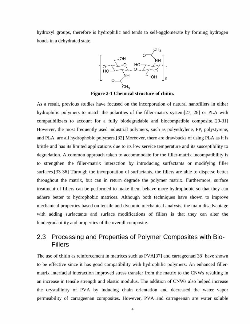
4
hydroxyl groups, therefore is hydrophilic and tends to self-agglomerate by forming hydrogen
bonds in a dehydrated state.
Figure 2-1 Chemical structure of chitin.
As a result, previous studies have focused on the incorporation of natural nanofillers in either
hydrophilic polymers to match the polarities of the filler-matrix system[27, 28] or PLA with
compatibilizers to account for a fully biodegradable and biocompatible composite.[29-31]
However, the most frequently used industrial polymers, such as polyethylene, PP, polystyrene,
and PLA, are all hydrophobic polymers.[32] Moreover, there are drawbacks of using PLA as it is
brittle and has its limited applications due to its low service temperature and its susceptibility to
degradation. A common approach taken to accommodate for the filler-matrix incompatibility is
to strengthen the filler-matrix interaction by introducing surfactants or modifying filler
surfaces.[33-36] Through the incorporation of surfactants, the fillers are able to disperse better
throughout the matrix, but can in return degrade the polymer matrix. Furthermore, surface
treatment of fillers can be performed to make them behave more hydrophobic so that they can
adhere better to hydrophobic matrices. Although both techniques have shown to improve
mechanical properties based on tensile and dynamic mechanical analysis, the main disadvantage
with adding surfactants and surface modifications of fillers is that they can alter the
biodegradability and properties of the overall composite.
2.3 Processing and Properties of Polymer Composites with Bio-Fillers
The use of chitin as reinforcement in matrices such as PVA[37] and carrageenan[38] have shown
to be effective since it has good compatibility with hydrophilic polymers. An enhanced filler-
matrix interfacial interaction improved stress transfer from the matrix to the CNWs resulting in
an increase in tensile strength and elastic modulus. The addition of CNWs also helped increase
the crystallinity of PVA by inducing chain orientation and decreased the water vapor
permeability of carrageenan composites. However, PVA and carrageenan are water soluble

5
polymers, therefore have limited applications. Another study presented the use of CNP, which
has a lower crystallinity than nanowhiskers, in a potato starch matrix to evaluate its mechanical
and water barrier properties.[28] Similar with the studies mentioned previously, an increase in
tensile strength and water vapor permeability was observed due to the addition of CNP. When
the lowest water vapor permeability was reached, further addition of CNP caused it to increase
due to the agglomeration of the chitin particles. Moreover, fully biodegradable composites such
as chitosan/PHB[39], nanocellulose/PLA[40], and CNW/PLA[29, 30] have been previously
investigated. The thermal stabilities of these composites tend to drop with increasing filler
content, but exhibited improvements in tensile stiffness and strength. However, due to the
limitations of PHB mass production and low service temperature of PLA, therefore either they
are not suitable for industrial production or incorporation into a wide range of applications.
Although some of the studies have shown significant improvements with the incorporation of
chitin, as a result of good bonding and dispersion, but as mentioned before, the ability to
transition these processing techniques to an industrial scale is more challenging compared to
conventional polymer composite processing such as melt blending. A study on chitosan/LLDPE
composite film prepared by melt compounding and film blowing showed potential for packaging
applications.[41] The addition of a maleated compatibilizer helped improve the interaction
between LLDPE and chitosan as it increased the tensile strength, but was lower when compared
to the neat polymer. Furthermore, no significant effects of the compatibilizer on the water and
oxygen barrier properties were observed, but the incorporation of chitosan decreased the oxygen
permeance while increasing the water vapor permeability. The increase in water vapor
permeability was explained by the water absorption of chitosan promoting the transmission of
water molecules.
In order to overcome the ability to disperse the fillers for the ease of processing, dried forms of
bio-nanofillers were developed through various drying processes such as freeze drying, spray
drying, and supercritical drying[42], and attempts have been made to directly melt compound
them with polymer. However, due to the agglomeration issue stated earlier, it was found that the
hydrogen bonds formed between dried bio-nanofillers are difficult to redisperse and
breakdown.[43] This was further correlated to the deteriorating mechanical properties and poor
resistance against water vapor diffusion. Alternatively, processing these natural nanofillers in a
hydrated state, by solvent casting, has been previously studied due to the ability of achieving a

6
good dispersion of the nanofillers within a matrix.[27, 28, 44] As a result, significant
improvements in mechanical, barrier properties were obtained, but solvent casting is not a
process that can currently be implemented into an industrial scale for mass production.
Additionally, a problem associated with solvent casting is the effects of solvent on the overall
properties of the end product and efficiency of solvent removal. Another method that has shown
to produce well dispersion of bio-nanofillers in PLA through electrospinning, but more
investigation is needed for the optimization of its properties.[26, 43]
More recently, to address the complications of dispersing dried fillers and scalability of
processing, melt mixing of bio-nanofiller suspensions in PLA have been previously examined to
analyze filler dispersion, and thermal and mechanical properties.[29-31] Nanowhisker loadings
ranging from 0.5 to 5 wt% were investigated. Thermal degradation was found to be an issue
during processing as a result of the solvolytic degradation of N,N-dimethylacetamide, which was
used as a swelling and separation agent, and hydrolysis of PLA. Morphology of the composites
revealed some dispersion of nanowhiskers accompanied by agglomerates. There was a noticeable
change in the size of the agglomerates as they increased with nanowhisker loading. Some
improvements in the elastic modulus and tensile strength were observed with the addition of the
nanowhiskers, however, addition of certain compatibilizers and modifications had also caused
weakening of the neat matrix. Since PLA is a common polymer used for packaging, barrier
properties is an important aspect of the material that should be examined, but it was not reported
in these studies.
2.4 Water Vapor Barrier Properties of Polymer Composites It is generally found that the incorporation of fillers into polymers lead to an increase in the
degree of crystallinity of the composite because the fillers can influence the nucleation of
crystals.[30, 45, 46] Furthermore, previous studies have investigated the effects of crystallinity
on the diffusion of water vapor and discovered that a rise in crystallinity can reduce the diffusion
coefficient of water vapor.[47, 48] This was explained by the structure of crystalline domains
and the orientation of polymer chains, which in turn affects the mobility of water vapor through
the composite. Additionally, putting fillers into a polymer forms a more tortuous path for water
vapor to travel across the composite. As a result, nanocomposites usually show better water
vapor resistance than the neat polymer matrix by itself, but is also dependent on the type of

7
filler.[28, 49, 50] Poor filler-matrix interfacial properties results in air gaps within the composite
that allows water vapor to diffuse easily through the material. A past research studied the water
absorption of composites with macro sized chitin waste incorporated into PP and showed an
increase in water absorption with increasing chitin loading as expected from the hydrophilicity of
chitin.[51] Fillers that can absorb, interact, or react with the permeating gas molecule can have
an effect on promoting or resisting the diffusion of vapor permeance through the composite.
2.5 Polypropylene Composites Polypropylene has good mechanical and barrier properties and is commonly used in packaging
applications [52, 53]. Many studies in the past have found to further enhance its properties by
incorporating nanofillers. More specifically, nanoclay/PP composites have been a widely studied
system that has shown improvements in thermal, mechanical, and barrier properties. A study on
melt blended organoclay/PP nanocomposites with and without compatibilizers at 5 to 15 wt%
nanoclay loadings for analyzing thermal, mechanical, and barrier properties found improvements
in degradation and melting temperature, tensile strength, and decrease in oxygen
permeability.[50] This showed that nanoclay is an effective filler for packaging materials.
Another study analyzed the thermal stability of nanoclay-polypropylene composites using TGA
and DSC and showed an increase in thermal stability, which was a result of the nanoclay
providing a stabilizing effect on the polypropylene.[54]
As discussed previously, the incorporation of additives into polymer is known to help maximize
its crystallinity due to the ability of additives to act as nucleating sites for crystallization. One of
many studies examined the effects of the addition of nanotubes on its crystallization and thermal
stability of PP nanocomposites [45]. As expected, the crystallinity and crystallization
temperature was found to increase with the addition of the nanotubes. Moreover, the composites
with nanotubes showed slight improvement in thermal stability based on TGA. This may have
been caused by the barrier effects of nanotubes, which reduced the speed at which the volatile
products escaped.
Furthermore, a study examined the thermal and mechanical properties of melt blended
chitosan/PP composites and an improvement in thermal stability and crystallinity was observed
with the incorporation of chitosan.[46] Another study investigated unidirectionally aligned
chitosan fiber/PP prepared by sandwiching the fibers between PP sheets through compression

8
molding.[55] In both these studies, an increase in tensile strength and elastic modulus were
observed. Moreover, the addition of chitosan resulted in a faster water uptake by the composites.
On the other hand, a decrease in crystallinity of PP was revealed from a study when
incorporating dried nanocellulose fibers [56]. However, the mechanical properties were
improved and its water absorption was also higher compared to the pure PP. The combination of
chitosan and cellulose nanocomposite films have been studied lots previously, but there is
limited research in the use of CNWs.
2.6 High Density Polyethylene Composites
One of the most commonly used polymer for such application is high density polyethylene
(HDPE). HDPE is a rigid polymer that has good water vapor barrier and chemical resistance
against strong acids and alkalis, but poor gas barrier properties.[57] As a result, HDPE is
commonly used in bottle packaging, pipes, and industrial containers. Many studies have
investigated the effects of incorporating conventional fillers such as montmorillonite[58, 59],
chrysotile[60], calcium carbonate[61], and talc[62] into HDPE composites to optimize oxygen
barrier and mechanical properties. However, the main concern of using these inorganic fillers is
the negative health and environmental impacts since they are not biodegradable and
renewable.[16]
2.6.1 Effects of Crystallinity on the Properties of HDPE
In order to understand some of the factors that control the properties of HDPE, a previous study
proposed that the film crystalline structure, melt relaxation rates of molten polyethylene, and
physical properties are some factors that can affect oxygen and moisture barrier of HDPE
films.[63] The crystalline structure of the films has an impact on the permeability of water and
oxygen because the size of the molecules can easily diffuse through amorphous regions, but are
too small to penetrate crystalline domains. Since HDPE has a high density due to its minimal
branching between polymer chains leading to a closed packed structure, therefore it is known to
have a high degree of crystallinity and good barrier properties.[64] Moreover, a recent study
examined co-extruded multilayered film systems to analyze the crystalline morphology of HDPE
at different layer thickness under confinement.[65] The confined spherulite morphology
generated provided a tortuous path for water and gas diffusion, hence enhancing barrier
properties. The correlation between crystallinity and barrier properties has also been observed

9
with other polymers including PLA[47] and PP[66]. Additionally, the stress relaxation rate of the
polymer melt determines orientation of the crystalline domains as a faster rate will result in a
more random orientation, which improves barrier properties.[63] Two of many polymer
properties that can affect barrier properties include melt index and density. Melt index is a
measure of the melt flow rate of a polymer on a mass per time basis. An increase in the melt
index of HDPE will reduce the water vapor transmission rate because it causes faster relaxation
times. Lastly, as mentioned earlier, polymers with a higher density will provide a more optimal
water vapor and oxygen barrier oppose to low density due to the direct correlation between
density and crystallinity.
2.6.2 Effects of Fillers on the Crystallinity and Properties of HDPE
One way to maximize crystal formation is through incorporating fillers, that can act as nucleating
agents, in polymer to promote crystallization.[62] The addition of fillers can also help reinforce
the matrix to enhance mechanical properties.[67] However, HDPE is known to be a hydrophobic
polymer and does not interact well with many conventional fillers, therefore the use of surface
modified fillers[68, 69] and polymers[70-72] have been previously tested so that they can
interact with each other better. Between the two, the most common and easy to scale is the
modification of the surface of polymers since the functional groups on fillers can vary greatly
and may be difficult to modify. More specifically, maleic anhydride is typically grafted onto
polymers as a coupling agent because it is easy to graft.[73] It also provides the appropriate
functional groups to accommodate for the polarity differences between the filler and matrix
improve the bonding between the two. The addition of a maleated compatibilizer can show
strong adhesion through the observation of the morphology of the composite.[71, 74] From a
visual inspection of the fracture surface of a composite, evidence of poor interfacial adhesion
includes voids and the pull-out of fillers whereas a strong interfacial adhesion would show some
plastic deformation and coating of the matrix onto the fillers. By increasing the filler-matrix
interfacial interaction, stress experienced by the matrix can be transferred to the filler for
improving the strength of the composite. Furthermore, enhancement in intermolecular interaction
can suppress crystallization and disrupt the original crystal structures of polymers.[39]
As a result of some of the effects mentioned, the use of fillers, such as cellulose fiber[74], carbon
nanotube[75], and nanoclay[70] in HDPE composites have found to be effective in enhancing

10
oxygen barrier, and thermal and mechanical properties. When low loadings of these filler were
added to the HDPE, a slight increase in crystallinity was observed, but decreased at higher filler
loadings. The decrease in crystallinity at higher filler loadings was explained by the fillers
restricting mobility of the polymer chains. Despite the decrease in crystallinity, the oxygen
permeability was still lower compared to the unfilled HDPE as a result of the fillers providing a
tortuous path for the gas molecules. Furthermore, any filler and matrix interaction with
permeants will also affect the permeability since it can cause the composite to be more absorbent
to certain molecules passing through the material.[76] Additionally, an increase in storage
modulus was observed with increasing filler content. However, reduction in stiffness was
observed with the addition of a compatibilizer due to plasticizing effects, but elongation at break
and toughness were increased.
2.6.3 Effects of Filler Dimensionality and Orientation on Crystallinity of HDPE
In addition to the filler-matrix interaction the dimensionality and orientation of the fillers also
has an effect on crystallinity, and mechanical and oxygen barrier properties. A study investigated
the effects of carbon nanofiller dimensionality on the isothermal and non isothermal
crystallization of HDPE.[77] One of the main differences between isothermal and nonisothermal
crystallization was the crystallization mechanism. For the case of the isothermal condition, a
nucleation-controlled mechanism applied whereas for the nonisothermal condition, crystal
growth was more dominant. Moreover, it was found that the orientation of the fillers from
processing the composites had an effect on crystallinity as well.[70] Biaxially stretched
composites had fillers exhibiting a preferred orientation and resulted in higher crystallinity than
compared to compression or blow molded films. The addition of compatibilizer was not found to
have an effect on the filler orientation.
2.7 Masterbatch Dilution of Polymer Composites In the recent years, masterbatch dilution of composites has been a popular processing technique
applied in research to investigate the ability to promote filler dispersion due to agglomeration of
fillers that can reside in the melt after a single step direct compounding process.[78] The
production of a masterbatch can help with the ease of processing composites industrially to avoid
the need to deal with fillers that are difficult to incorporate into polymers. Moreover, the

11
properties of composites can be tailored by blending different additives and polymers with the
masterbatch. One of the most studied polymer composites with masterbatch dilution involves the
use of MWCNT in PP.[49, 79-81] Generally, the addition of MWCNT resulted in an increase in
crystallinity, elastic modulus, yield stress, storage modulus, viscosity, and a decrease in ductility
of the composites. The further of the addition of a compatibilizer improved filler-matrix
interaction and also increased mechanical properties, but it hindered the increase in dispersion,
crystallinity, and viscosity. It was suggested that a polarity mismatch between the polar regions
of the compatibilizer and the nonpolar base matrix caused difficulties in dispersion. The
compatibilizer also interfered with the stacking of PP chains causing some decrease in
crystallinity compared to MWCNT without the compatibilizer but still higher than neat PP.
However, the studies found that existing agglomerates from the masterbatch could not be
effectively dispersed in the dilution process. In addressing the effects of dispersion, one study
examined the dispersion of MWCNT in PLA under different processing conditions for
masterbatch production and its dilution process.[78] It was determined that a twin screw extruder
operating at a faster screw speed of generated composites with better dispersion and less number
of agglomerates. This was consistent for the dilution process as well, therefore it proved that the
extra step in diluting a masterbatch can help with increasing dispersion and minimizing
agglomerates. The initial dispersion of MWCNT in the masterbatch also had an effect on how
well dispersed they were in the composite was after dilution.
Other masterbatch studies of nanoclay[49, 82-84], graphite[85, 86], layered silicate[87], and
carbon black[88] polymer composites have also been tested and showed improvements in
electrical, mechanical, thermal, barrier and flame retarding properties. However, the demand for
environmentally sustainable composites have triggered investigations in the development of
masterbatches using natural and biodegradable fillers such as cellulose, chitosan, and chitin in
PLA and polyethylene.[89-91] Masterbatch dilution of these composites have been previously
evaluated based on thermal, mechanical, and barrier properties. In regards to thermal properties,
the thermal stabilities tend to drop due to natural fillers being more susceptible to degradation
than the polymer itself, but the crystallinity increases as a result of crystal nucleation from the
fillers. Tensile modulus and strength also increase since the fillers help reinforce the polymer,
though the presence of a compatibilizer can have slight drawbacks. However, the barrier
properties of the composites have either found to deteriorate or not greatly affected by the fillers.

12
All of these studies showed the comparisons of the diluted composites relative to its neat
polymer matrix, but did not show the value of using a masterbatch dilution over directly
compounded composites. Therefore, to evaluate the effectiveness in masterbatch dilution, the
mechanical properties of directly compounded CNW/PLA composites[92] have been compared
to diluted CNW/PLA[89] composites. Both composites are found to have higher elastic modulus
and tensile strength than pure PLA, but the directly compounded CNW/PLA composites had
slightly better mechanical properties than diluted composites, but it was also important to note
that the diluted composites also contained talc. Although PLA has advantage over other
polymers due to its biodegradability, there still exist degradation issues when processing at high
temperatures with aqueous solutions and solvents.[29-31]
2.8 Summary This chapter provided an outline of various polymer nanocomposite systems and processing
techniques that have been previously studied. The complications in processing natural fillers
over conventional fillers have also been addressed. Also, the importance of nanofiller dispersion
and its effects on polymer crystallinity has also been discussed relative to the properties of the
nanocomposites. Moreover, masterbatch dilution, which is process applicable towards large scale
production, has been reviewed based on existing research. The following sections will give a
thorough analysis of the relationship between the structure and properties of the composites
processed by the different methods applied in this thesis.

13
Chapter 3 Chitin Nanowhisker/Polypropylene Composites
The combination of various studies has shown the potential of bio-nanofillers to replace existing
inorganic fillers as they are able to provide effective enhancement in different material
properties. However, current studies lack the examination of CNW composites in a polymer
matrix that is not susceptible to degradation and the investigations of water vapor barrier
properties, which is crucial to many applications. This study aims to explore the use of direct
melt blending of CNW/PP composites to analyze the effects of the incorporation of CNW and
compatibilizer into polypropylene on its thermal, barrier, mechanical, and rheological properties.
Moreover, connections between the properties at high and low weight percentages of CNW will
be detailed to provide a better understanding of the behaviors that they exhibit. Lastly, the
scalability of the process based on the performance of the composites will be evaluated.
3.1 Materials and Methods for Fabrication of CNW/PP Composites
3.1.1 Materials for CNW/PP Composite Fabrication
CNW suspension supplied by BOCO Technology Inc. was used as the composite filler and its
chemical structure is provided in Figure 2-1. Its aspect ratio (L/W) is approximately 20-50 and
density is 1.45 g•cm-3. The composite matrix used in this study was a homopolymer PP
(ExxonMobil AchieveTM 3854) with a density of 0.9g•cm-3 and the compatibilizer was a
maleated PP (EastmanTM G-3003 Polymer).
3.1.2 Fabrication of CNW/PP Composites
A co-rotating twin screw micro compounder (DSM Xplore® MC 15) was used to melt blend the
CNW/PP composites. The PP and MAPP were mixed with the CNWs and fed into the
compounder operating at 170°C and 200 rpm. Moreover, the amount of CNW suspension added
was based on its concentration, which was used to determine its dried weight percent, and the
four main compositions processed were 1, 2, 5, and 10 wt% CNW in PP. Additionally, two sets
of the four compositions, with and without compatibilizer, were prepared to investigate both the
effects of the CNW and the compatibilizer on the composite. In this study, the composites with

14
and without compatibilizer are denoted by CNW/PP and CNW/MAPP respectively following
their weight percentages. A set of neat PP was also processed before testing to have consistent
thermal and processing history with the other compositions for comparison. The compounded
material extruded from the compounder was then pelletized for further processing.
The pelletized compound containing CNW and PP were either compression molded using a
hydraulic hot press (Carver, Inc.) or injection molded using a micro injection molding machine
(DSM Xplore® IM 5.5). Composite films, less than 200 µm in thickness, were prepared by
compression molding at 180°C and 1000 psi in a thin mold for water barrier testing. The samples
for rheological testing were also compression molded under the same conditions but slow cooled
and using a different mold that provided rectangular samples with the dimensions of 10 mm by
18 mm by 0.7 mm. For mechanical testing, the samples were prepared by injection molding at
180°C and 100 psi to produce type IV specimens. A schematic of all the processing methods
used in this study are shown in Figure 3-1.
(a)
(b)
(c)
Figure 3-1 Schematic of melt compounding (a), compression molding (b), and injection
molding (c) processing methods.
3.1.3 Characterization of CNW/PP Composites
3.1.3.1 Morphological Analysis
Morphology of the CNWs and melt compounded CNW/PP and CNW/MAPP composites were
analyzed using scanning electron microscopy (SEM) and atomic force microscopy (AFM) to see

15
the dispersion of the CNWs in the PP matrix. An ultra-high resolution SEM (Hitachi UHR-SEM
SU8230) was used for examining dried CNWs and nitrogen fractured cross section surfaces of
the composites. The specimens were sputter coated with platinum prior to SEM imaging to
minimize charging at the surface of the sample. An atomic force microscope (Bruker) was used
to further confirm observations from the SEM imaging for the dried CNWs and microtomed
cross sections of the composites.
3.1.3.2 Thermal Analysis
The thermal stability of the PP and CNW/PP composites were observed through TGA by using
the TGA Q50 (TA Instruments) under nitrogen atmosphere. Samples were heated at a rate of
20°C/min. from room temperature (25°C) to 600°C to ensure complete thermal degradation. The
degradation temperatures of each composition were determined from the weight change curves.
Further thermal analysis of the PP and CNW/PP composites were performed through DSC by
using the DSC Q2000 (TA Instruments) under nitrogen atmosphere. This helped measure the
enthalpy of fusion, and melting and crystallization temperature of the composites. A heat-cool
cycle between room temperature (25°C) and 200°C at a rate of 10°C/min. was used so that the
composites were tested below their degradation temperatures.
3.1.3.3 Water Vapor Barrier Analysis
Water permeance of the CNW/PP and CNW/MAPP composite films were measured using the
water method mentioned in ASTM E96 by monitoring the weight change the test dishes over a
period of one to three weeks to ensure steady weight loss was achieved. Each test dish contained
the same volume of water to begin with and had the compression molded films mounted on top
of them. The test dishes were kept in an incubator at a controlled temperature and humidity,
which were 50°C and 0% RH respectively, throughout the duration of the test. Three samples of
each composition were prepared for comparison and the rate of water loss was extracted from a
linear fit of the plot of weight change with respect to time at the end of each test. Further
calculations were performed to obtain the values for water vapour transmission and permeance.
3.1.3.4 Mechanical analysis
The Microtester 5848 (Instron) was used for tensile testing based on ASTM D638 standard using
a Type IV tensile specimen. An average of four to six samples for each composition was taken to

16
ensure consistency of the results. The elastic modulus, ultimate tensile strength, and elongation
strain at break were extracted from the tensile curves for comparison.
3.1.3.5 Rheological analysis
A extensional viscosity test was performed on the ARES rheometer (TA Instruments) with the
extensional viscosity fixture, was used to measure the extensional viscosity of the composites at
a temperature and strain rate of 180°C and 1.0s-1 respectively. An average of three samples for
each composition was taken for the test.
3.2 Results and Discussion of CNW/PP Composites
3.2.1 Morphology of CNW and CNW/PP Composites
Morphological analysis of the composites was important because it provided information on the
quality of the material produced from the specified processing method based on filler dispersion.
It also helped predict some of the material properties. The initial AFM and SEM images shown
in Figure 3-2 presents the dried form of CNW fillers used in this study.
(a)
(b)
Figure 3-2 AFM (a) and SEM (b) images of the morphology of dried CNWs.
The height image from the AFM of the dried CNWs confirmed the nanoscale of the
nanowhiskers based on their observed high aspect ratios. A higher magnification of the dried
CNWs under SEM showed the agglomeration of the CNWs as stated before from the hydrogen
bonds that they form with each other when dehydrated, hence a fibrous mat is formed.
As for the AFM of the CNW composites, a constant force, that was able to deform the PP matrix,
was applied throughout the sample to perform a modulus mapping of the surface since it was

17
known that the modulus of CNWs is higher than neat PP. This helped confirm the existence of
the CNWs and its dispersion observed in the SEM images of the composites. Comparisons
between the morphologies of the various CNW/PP compositions using AFM and SEM are
shown below in Figure 3-3.
(a)
(b)
(c)
(d)
(e)
(f)
(g)
(h)
Figure 3-3 AFM images of the cross sections of neat PP (a), 2% (b), 5% (c), and 10% (d)
CNW/MAPP, and SEM images of the cross sections of 2% (e), 5% (f), and 10% (g)
CNW/MAPP, and 10% CNW/PP.
In the AFM images, the light and dark areas indicated higher and lower modulus respectively.
Since CNWs have a higher modulus, therefore, they appeared as the lighter areas where as the
darker areas were representative of the PP matrix.AFM of the neat PP was provided as a control
sample to verify the integrity of what is observed in the composites containing CNWs. The AFM
images of Figure 3-3(b), (c), and (d) corresponded to the SEM images of Figure 3-3(e), (f), and
(g). In the AFM images, it was evident that the dispersion of the CNWs were not completely
uniform and slight agglomeration of the CNWs had occurred. In the SEM images, the CNW
agglomerates appeared as nanosized circular particles because of two possible reasons. The first
being that the agglomerates are seen as the cross sections of the CNWs and the second being the
actual formation of dried spherical particles as a result of the processing method. The latter
reasoning is more likely as it can be explained by the drying of a droplet of CNW
18
suspension.[42] This is because during melt blending, it was possible for the suspension to break
up into droplets from the shear forces and subsequent water removal.
The AFM image of the 2% CNW/MAPP composite did not show any large CNW particles,
which suggested a good dispersion but with minimal agglomeration as seen in its SEM image. At
5% CNW loading, a noticeable amount of agglomerates are dispersed throughout the PP matrix,
but the size of the agglomerates are still comparable with the agglomerates at 2% CNW loading.
In the images of the composites at 10% CNW loading, there was a substantial increase in the size
of the agglomerates when compared with the composites at lower CNW loadings, however,
dispersion of the agglomerates was maintained.
Between the 10% CNW/MAPP and CNW/PP composites, no significant differences were
observed since the dispersion and agglomeration look similar. Moreover, based on the AFM and
SEM images, the interfacial interaction between the CNW and PP was difficult to detect due to
the limitations of the probe tip size of the AFM and the issues with charging at high
magnifications for polymer composites, which are nonconductive, in the SEM. Although a
considerable amount of agglomerates were formed, the dispersion of the agglomerates may still
serve as an advantage for certain properties. Therefore, the dispersion of the CNWs in the
composites is a critical aspect to know as it will be seen the effects it has on the properties
addressed in the following sections.
3.2.2 Thermal Properties of CNW/PP Composites
Thermal stabilities of the CNW/PP and CNW/MAPP composites were analyzed using their
respective TGA and DSC curves. The onset temperature of degradation was determined using
the TA Universal Analysis software. For the analysis of the crystallinity, and melting and
crystallization temperatures of the composites, the first heating and cooling curve from the DSC
was used for analysis for comparing the materials as processed. The degree of crystallinity of the
composites were calculated based on the enthalpy of fusion values obtained from the melting
curves of each composition using the TA Universal Analysis software and the following
equation:
𝑋𝑋𝑐𝑐 = ∆𝐻𝐻𝑓𝑓∆𝐻𝐻𝑓𝑓
𝑜𝑜 ∙WPP× 100% {1}

19
In equation {1}, 𝑋𝑋𝑐𝑐 (%), ∆𝐻𝐻𝑓𝑓 (J/g), WPP , and ∆𝐻𝐻𝑓𝑓𝑜𝑜 (J/g) are the degree of crystallinity, the
enthalpy of fusion of the experimental sample, weight fraction of PP, and the enthalpy of fusion
of the 100% crystalline polymer respectively. The enthalpy of fusion of a 100% crystalline
polypropylene used in this study was 207 J/g, which was retrieved from the literature.[93] Figure
3-4 and Table 3-1 below shows the TGA and DSC curves for analyzing the thermal properties of
all the composites.
(a)
0
10
20
30
40
50
60
70
80
90
100
25 140 255 370 485 600
Wei
ght C
hang
e [%
]
Temperature [°C]
PP1% CNW/PP2% CNW/PP5% CNW/PP10% CNW/PP
0102030405060708090
100
450 460 470 480 490 500

20
(b)
(c)
0
10
20
30
40
50
60
70
80
90
100
25 140 255 370 485 600
Wei
ght C
hang
e [%
]
Temperature [°C]
PP1% CNW/MAPP2% CNW/MAPP5% CNW/MAPP10% CNW/MAPP
0
10
20
30
40
50
60
70
80
90
100
450 460 470 480 490 500
-2
-1.5
-1
-0.5
0
0.5
1
1.5
2
2.5
3
80 100 120 140 160 180
Hea
t Flo
w [W
/g],
Exo
Up
Temperature [°C]
PP1% CNW/PP2% CNW/PP5% CNW/PP10% CNW/PP

21
(d)
Figure 3-4 TGA curves for CNW/PP composites (a) and CNW/MAPP composites (b), and
heat-cool DSC curves for CNW/PP composites (c) and CNW/MAPP composites (d).
Table 3-1 Thermal properties extracted from TGA and DSC curves.
Sample Degradation Onset Temperature [°C]
Melting Temperature [°C]
Crystallization Temperature [°C] Crystallinity [%]
Neat PP 469.37 156.97 109.05 28.79
1% CNW/PP 481.80 151.67 116.60 37.35
2% CNW/PP 475.37 151.29 116.59 35.84
5% CNW/PP 473.10 152.69 116.46 37.96
10% CNW/PP 471.36 152.70 116.86 39.89
1% CNW/MAPP 480.80 150.76 115.70 39.01
2% CNW/MAPP 474.70 151.03 115.66 37.68
5% CNW/MAPP 472.91 152.94 114.65 37.32
10% CNW/MAPP 474.19 157.14 114.99 38.77
From the TGA curves, the onset of degradation was at a higher temperature for both the
CNW/PP and CNW/MAPP composites in contrast with the neat PP. An increase of up to 12°C
-2
-1
0
1
2
3
4
80 100 120 140 160 180
Hea
t Flo
w [W
/g],
Exo
Up
Temperature [°C]
PP1% CNW/MAPP2% CNW/MAPP5% CNW/MAPP10% CNW/MAPP

22
was observed, which may have resulted from the enhanced heat transfer provided by the CNW
dispersed within the matrix to help dissipate the heat. This correlated with the rate of degradation
that was reduced with the addition of CNW. Therefore, the addition of CNW showed
improvements in the thermal stability of the composite, but at CNW loadings greater than 1 wt%,
the thermal stability of the composite gradually decreased and approached the thermal
degradation properties of neat PP. This was possibly due to agglomeration of CNWs resulting in
the dispersion of larger particles, which provided less effective heat dissipation.
Similarly, the crystallization temperature and degree of crystallinity of both the CNW/PP and
CNW/MAPP composites were higher than the neat PP. This suggested that the CNWs acted as
nucleation sites in promoting crystallization, however, the crystallinity of the composites did not
increase after the addition of 1 wt% CNW due to the agglomeration of the CNWs at higher wt%.
The ability of fillers to induce crystallization in PP has been shown by past studies through the
formation of a transcrystallinity layers at the filler-matrix interface.[94] Since the PP used in this
study did not inherently have a high crystallinity, the potential of crystal growth restriction was
minimized. Although agglomerates formed at higher wt%, the degree of crystallization still
increased because the larger particulates remained as nucleation sites for crystallization. On the
other hand, the melting temperature of both the CNW/PP and CNW/MAPP composites
decreased when compared to the neat PP. The reason for this is because CNWs can act as
impurities in the matrix and allow polymer chains to move more freely, therefore increasing the
entropy of fusion of the composite and lowering the melting temperature. Between the CNW/PP
and CNW/MAPP composites, no significant differences were observed with the added
compatibilizer in terms of the overall thermal properties.
3.2.3 Water Vapor Barrier Properties of CNW/PP Composites
The plots of weight change against time for each set of compositions were generated from the
weight measurements gathered and are shown in Figure 3-5(a) and Figure 3-5(b). A linear fit was
applied to each set of data and the slope, which represented the rate of water vapor travelling
across the film, was obtained for calculations of the WVT and WVP. The equations provided by
the ASTM E96 standard to calculate these values are as follows:
WVT = Gt∙A
{2}

23
WVP = WVTS∙(R1−R2)
{3}
In equation {2}, G (g) is the weight change, t (hours) is the time, and A (m2) is the test area of the
specimen. This equation helped determine the rate at which the water vapor was flowing through
the sample. In equation {3}, S (Pa) is the saturation vapour pressure at the test temperature, R1 is
the relative humidity inside the test dish expressed as a fraction, and R2 is the relative humidity
of the test chamber expressed as a fraction. Similar to equation {2}, equation {3} quantified the
rate of water vapor transmission through the film, but it also considered the pressure difference
induced by the temperature and humidity. The water vapor permeance of all the compositions
plotted with respect to CNW loading is shown in Figure 3-5.
(a)
-0.7
-0.6
-0.5
-0.4
-0.3
-0.2
-0.1
0
0 50 100 150 200 250 300 350 400
Wei
ght C
hang
e [g
]
Time [hours]
PP1% CNW/PP2% CNW/PP5% CNW/PP10% CNW/PP
24
(b)
(c)
Figure 3-5 Weight change vs. time curves of CNW/PP (a) and CNW/MAPP (b) composites,
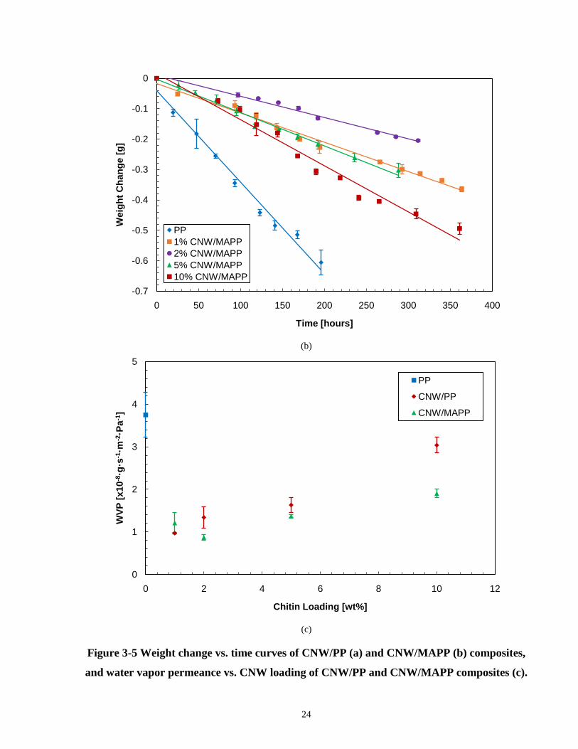
and water vapor permeance vs. CNW loading of CNW/PP and CNW/MAPP composites (c).
-0.7
-0.6
-0.5
-0.4
-0.3
-0.2
-0.1
0
0 50 100 150 200 250 300 350 400
Wei
ght C
hang
e [g
]
Time [hours]
PP1% CNW/MAPP2% CNW/MAPP5% CNW/MAPP10% CNW/MAPP
0
1
2
3
4
5
0 2 4 6 8 10 12
WVP
[x10
-8·g
·s-1
·m-2
·Pa-
1 ]
Chitin Loading [wt%]
PP
CNW/PP
CNW/MAPP

25
Based on the water loss curves of both CNW/PP and CNW/MAPP composites, the addition of
chitin was observed to decrease the amount of water loss over time. Furthermore, the
CNW/MAPP composites showed a smaller decrease overall when compared to the CNW/PP
composites. Upon examination of the change in WVP with chitin loading, it was found that the
minimum WVP occurred at low weight percentages of CNW and began to increase at higher
weight percentages. This was consistent with a previous study that had observed a similar trend
in WVP of chitin nanoparticles in starch where the addition of chitin nanoparticles showed a
decrease in WVP at low loading and then began to increase, which was explained due to the
formation of agglomerates.[28] The optimal WVP of the composites were at 1 and 2% CNW
loading for CNW/PP and CNW/MAPP respectively. This can be explained by the dispersion of
CNW over a large surface area in the PP impeding the diffusion of water vapor across the film.
Additionally, the effects of compatibilizer was not as pronounced at lower CNW loadings
whereas the decrease was more significant at higher CNW loadings, which suggested that the
compatibilizer was more effective at higher CNW loadings.
From the results obtained, the three main factors that could have contributed to the decrease in
WVP of the composites includes the effects of the filler, crystallinity, and compatibilizer. Firstly,
the inclusion of the CNW in PP created a more tortuous path for the water vapour to pass
through. At higher CNW loadings, the WVP did not continue to reduce due to larger
agglomerates of the CNW as observed from the SEM and AFM images shown previously. This
lowered the amount of particles, which blocked the paths for water vapor to pass through.
Furthermore, CNW is hydrophilic, therefore it was possible for the CNWs entrapped in the
matrix to absorb the water vapour as it tried to pass through the composite film. As a result, the
rate of diffusion of the water vapour through the composite was reduced. Additionally, the CNW
in the PP influenced the crystallization of the polymer causing an increase in the crystallinity of
the composite as shown from the DSC data earlier. As mentioned earlier, due to the morphology
of crystalline domains, small molecules generally cannot penetrate through them.[47] Since the
degree of crystallinity of the composites at higher CNW loading were comparable to the lower
CNW loading composites because of the CNW particles inducing crystallization, therefore the
WVP remained below the neat PP. Lastly, the addition of the compatibilizer had two possible
effects to lower the WVP of the composites. The partial hydrophilic nature of the compatibilizer
could have interacted with the water to slow its diffusion pass the composite. Moreover, the

26
purpose of the compatibilizer was to help enhance the interaction between the filler and the
matrix since poor interaction can lead to interfacial gaps resulting in an increase in WVP.
Therefore the compatibilizer indicated improvements in CNW and PP interaction as the WVP of
the CNW/MAPP composites were lower than the CNW/PP composites.
3.2.4 Mechanical Properties of CNW/PP Composites
Tensile properties of the CNW/PP and CNW/MAPP composites in terms of elastic modulus,
ultimate tensile strength, and elongation strain at break were extracted and plotted against their
respective compositions in Figure 3-6.
(a)
600
700
800
900
1000
1100
1200
1300
1400
1500
0 2 4 6 8 10 12
Elas
tic M
odul
us [M
Pa]
Chitin Loading [wt %]
PPCNW/PPCNW/MAPP

27
(b)
(c)
Figure 3-6 Elastic modulus (a), ultimate tensile strength (b), and elongation strain at break
(c) of CNW/PP and CNW/MAPP composites at 1, 2, 5, and 10 wt% CNW loading.
20
25
30
35
40
45
0 2 4 6 8 10 12
Ulti
mat
e Te
nsile
Str
engt
h [M
Pa]
Chitin Loading [wt %]
PPCNW/PPCNW/MAPP
0
0.5
1
1.5
2
2.5
0 2 4 6 8 10 12
Elon
gatio
n St
rain
at B
reak
[%]
Chitin Loading [wt %]
PPCNW/PPCNW/MAPP

28
The elastic modulus of both the CNW/PP and CNW/MAPP composites showed an improvement
compared to the neat PP. This increase in elastic modulus was expected since it typically
improves with the incorporation of rigid fillers in a polymer matrix.[3, 4, 12, 29] The optimal
compositions were at found to be at 2 and 5 wt% CNW loading for the CNW/PP and
CNW/MAPP respectively as an increase of up to 20% in the stiffness was observed. Similarly,
the ultimate tensile strength of the CNW/PP and CNW/MAPP composites also showed an
increase compared to the neat PP and had the same optimal compositions as the elastic modulus.
An increase of 17% in the ultimate tensile strength was observed. The increase in mechanical
properties suggested that the CNW showed some reinforcement of the PP from its ability to take
on the stress transferred from the matrix. Furthermore, it was possible for transcrystallinity to
occur at the CNW-PP interface, which causes crystals to grow perpendicular to the fiber axis,
and increase its interfacial strength.[94] It was also suspected that the partially well dispersed
CNWs helped strengthened the mechanical properties by forming a stress distribution throughout
the composite oppose to one localized area. The low standard deviation within the values for
each composition further supported the uniformity of the dispersion of the CNWs throughout the
matrix. Moreover, the purpose of adding a compatibilizer was to improve the bonding between
CNW and PP and the dispersion of CNW in PP. However, the use of the compatibilizer did not
show effective reinforcement until 5 wt% loading, where the elastic modulus and tensile strength
surpassed the composite without compatibilizer. At lower CNW loading, the use of
compatibilizer seemed to hinder oppose to enhance the mechanical properties of the composite.
Additionally, at 10 wt% CNW loading, the elastic modulus and ultimate tensile strength began to
greatly decrease due to a rise in agglomeration and agglomerate size acting as stress
concentrators and deteriorating the overall mechanical properties of the composites. This was
consistent with many other polymer composites studied previously.[21, 29, 30, 50] Although the
elastic modulus and ultimate tensile strength at 10 wt% CNW was not at high as the optimal
values, the mechanical properties were still comparable to the neat PP possibly due to the
partially well dispersed agglomerates.
As for the elongation strain at break, there was a dramatic reduction upon the slightest addition
of CNW for both the CNW/PP and CNW/MAPP composites. They continued to decrease with
further CNW addition because the composite became rigid and started behaving like a brittle
material. There are two different phenomena that can explain this trend. At low CNW loading,

29
the reinforcing fillers restrained the movement of the matrix causing limited elongation at break.
Alternatively, at high CNW loading, the introduction of larger agglomerates created localized
stress concentration within the composite, which caused the composite to fail early without
exhibiting much reinforcement. Further analysis of the composites was done using a rheological
test in the next section to verify some of the behaviors exhibited by the composites.
3.2.5 Rheological Properties of CNW/PP Composites
A uniaxial extension test was performed on the composites to determine their elongation
viscosities, which is defined as the extensional stress over the strain rate. The rheological
properties of the CNW/PP and CNW/MAPP composites based on elongation viscosity are
presented in Figure 3-7.
(a)
100
1000
10000
0.01 0.1 1 10
Exte
nsio
nal V
isco
sity
[Pa·
s]
Elongation Time [s]
PP2% CNW/PP5% CNW/PP10% CNW/PP

30
(b)
Figure 3-7 Extensional viscosity vs. elongation time curves of CNW/PP (a) and
CNW/MAPP (b) composites.
The extensional viscosity of the CNW/PP composites did not show much change from one
composition to another since it is suspected that there were minimal interactions between the
hydrophilic CNW and hydrophobic PP. In contrast, extensional viscosity of the CNW/MAPP
composites increased with increasing CNW loading. This meant that a higher stress was required
for deformation. This indicated reinforcement between the CNWs and PP matrix because of the
enhanced interfacial bonding between them with help of the compatibilizer. As a result, the
composite showed resistance against flow of the when the strain was applied. Similar to a
previous study, comparisons between composites with and without compatibilizers were
investigated using a rheological test.[95] No improvements were observed in its rheological
properties without the compatiblizer, whereas it improved with increasing filler content of the
compatibilized composites. The results from the extensional viscosity test is useful for future
development in identifying the optimal processing conditions of the composites. More
specifically, it is important for the processing of the composites using fiber spinning, film
blowing, or blow molding.
100
1000
10000
0.01 0.1 1 10
Exte
nsio
nal V
isco
sity
[Pa·
s]
Elongation Time [s]
PP2% CNW/MAPP5% CNW/MAPP10% CNW/MAPP

31
3.3 Summary In this section, the morphological, thermal, barrier, mechanical, and rheological properties of
melt blended CNW/PP and CNW/MAPP composites with CNW loading ranging from 1 to 10
wt% have been investigated. Results have shown the potential of using CNW to replace current
inorganic fillers in polymers for packaging applications. These composites are suitable for
environmentally friendly industrial packaging applications as proven by its improved thermal
stability, water barrier properties, and strength when compared to neat PP. The significant
enhancement in the material properties of the composites were supported by the partially well
dispersion of CNWs in the PP matrix observed by AFM and SEM and the reinforcement of the
CNW and PP bonding through the use of a compatiblizer. Additionally, the CNWs had a positive
impact on the degree of crystallinity of the composites, which greatly improved its water vapor
barrier properties. Based on the water vapor transmission test results, it was proposed that the
water vapor barrier properties of the composites can be tailored via adjusting the CNW loading
in the polymer. The mechanical properties of the composites at their optimal compositions
exhibited a significant improvement in its elastic modulus and ultimate tensile strength. This was
further backed by the rheological test, which revealed an increase in the extensional viscosity
with the addition of CNW for the compatibilized composites. It was evident that the addition of
CNW and compatibilizer helped strengthen the composite. Although agglomeration was
observed at higher CNW loading, the dispersion of the agglomerates. It is possible that further
processing, such as a dilution process, can help to break down the agglomerates. Also, since melt
compounding is a scalable process, therefore it can be easily incorporated into an industrial scale
production. Lastly, through the knowledge obtained from this study, further optimization studies
of the composites can be performed to maximize their respective properties for tailoring towards
specific applications.

32
Chapter 4 Chitin Nanowhisker/High Density Polyethylene Composites
In this chapter, melt blended chitin nanowhisker (CNW)/high density polyethylene (HDPE)
composites were characterized for their morphological, thermal, barrier, mechanical, and
rheological properties. Moreover, the effects of various CNW loadings and the addition of a
maleated polyethylene compatibilizer on these properties were investigated.
4.1 Materials and Methods for Fabrication of CNW/HDPE Composites
4.1.1 Materials for CNW/HDPE Composite Fabrication
A homopolymer HDPE (ExxonMobilTM HDPE HD 6908) with a density and melt index of 0.965
g·cm-3 and 8.2 g/10 min respectively was used as the matrix. CNW provided by BOCO
Technology Inc. with an aspect ratio (L/W) and density of approximately 20-50 and 1.45 g·cm-3
respectively was used as the filler. Lastly, a maleic anhydride grafted polyethylene (Westlake
Epolene® C-26) with a density and melt index of 0.92g·cm-3 and 8 g/10 min respectively was
used as the coupling agent for the CNW and HDPE for this study.
4.1.2 Fabrication of CNW/HDPE Composites
CNW/HDPE composites were melt blended using a co-rotating twin screw micro compounder
(DSM Xplore® MC 15) at various compositions. The HDPE, MAPE, and CNWs were fed into
the compounder, which was operating at a temperature and screw speed of 170°C and 200 rpm
respectively. The two main sets of compositions prepared consists of CNW/HDPE composites
with and without the addition of a compatibilizer. Furthermore, the two types of composites for
with and without compatibilizer are denoted by CNW/HDPE and CNW/MAPE respectively
following their weight percentage CNW loading. Within those sets of compositions, a range of
CNW loading between 1 to 10 wt% was used.
The composites extruded from melt blending were pelletized and processed further through
compression molding using a hydraulic hot press (Carver, Inc.) or injection molding using a
micro injection molding machine (DSM Xplore® IM 5.5). Specimens for water vapor

33
transmission test and rheological testing were prepared using compression molding, and the
samples for mechanical testing was prepared using injection molding. For compression molding,
molds containing the specified geometries of the specimens were compressed under a
temperature and pressure of 180°C and 100 psi respectively and subsequently quenched. The
films for water barrier testing were less than 200 µm in thickness and the dimensions of the
rheological specimens were a disk with a diameter and thickness of 25 mm and 1.1 mm
respectively. Moreover, for injection molding, the samples were formed by molten material at a
temperature of 180°C and injected into a mold at a pressure of 100 psi.
4.1.3 Characterization of CNW/HDPE Composites
4.1.3.1 Microscopy Analysis
Atomic force microscopy (AFM) and scanning electron microscopy (SEM) were used for cross
sectional analysis of the composites for observing its morphology and dispersion of CNWs in the
HDPE matrix. The samples for AFM (Bruker) were prepared using a microtome to flatten the
cross section prior to imaging. On the other hand, SEM was performed using the Quanta FEG
250 ESEM (FEITM) and the samples were prepared by nitrogen fracturing and gold sputter coated
prior to imaging. The coating was required for dissipating the charge build up at the surface
during imaging.
4.1.3.2 Thermal Testing
TGA and DSC were used for the thermal analysis of HDPE and CNW/HDPE composites. The
TGA Q50 (TA Instruments) was used under nitrogen atmosphere with a temperature ramp of
20°C/min from room temperature (25°C) to 600°C for examining thermal stabilities of the
composites. Moreover, the DSC Q2000 (TA Instruments) was used under nitrogen atmosphere
with a heat-cool cycle between room temperature (25°C) and 200°C at a heating and cooling rate
of 10°C/min for determining the enthalpy of fusion, and melting and crystallization temperature
of the composites.
4.1.3.3 Water Vapor Barrier Testing
The water vapor transmission rate of the HDPE, CNW/HDPE and CNW/MAPE composite films
were determined by the water method from ASTM E96. Three film samples of each composition
were prepared and mounted onto test dishes containing a water level of approximately 1.9 cm
34
away from the film. The test dishes were placed in an incubator throughout the test at a
controlled temperature and humidity of 50°C and 0% RH respectively. Weight changes of the
test dishes were monitored over a period of one to three weeks until a steady weight loss was
observed. From the constant weight change, the WVT was obtained to calculate for the WVP.
4.1.3.4 Mechanical Testing
Tensile testing of the composites was performed following the ASTM D638 standard through
using Type IV specimens on the Microtester 5848 (Instron) machine. An average from four to
six specimens for each composition was tested. Stress-strain curves were obtained from the
testing and were further analyzed to determine the elastic modulus, ultimate tensile strength, and
elongation strain at break.
4.1.3.5 Rheological Testing
Rheological measurements were gathered using the ARES rheometer (TA instruments) with a
parallel plate geometry. A strain sweep was first testedon the HDPE at a temperature, frequency,
and strain rate range of 160°C, 0.99 rad/s, and 0.01 to 100% respectively. This was used to
determine the strain rate at which the material was within its linear viscoelastic region and was
evaluated to be 6%. The dynamic frequency sweep test was then performed on all the composites
at a temperature, strain rate, and frequency range of 160°C, 6%, and 0.1 to 200 rad/s
respectively. An average of three specimens for each composition were tested.
4.2 Results and Discussion of CNW/HDPE Composites
4.2.1 SEM and AFM of CNW/HDPE Composites
Morphology of the CNW/HDPE and CNW/MAPE composites were analyzed using the SEM and
AFM images depicted in Figure 4-1. More specifically, the focus was to examine the dispersion
of CNWs in the HDPE matrix. The use of AFM helped confirm the CNW dispersion observed in
the SEM images through mapping the modulus at a constant force applied over a cross sectional
area of the composites.
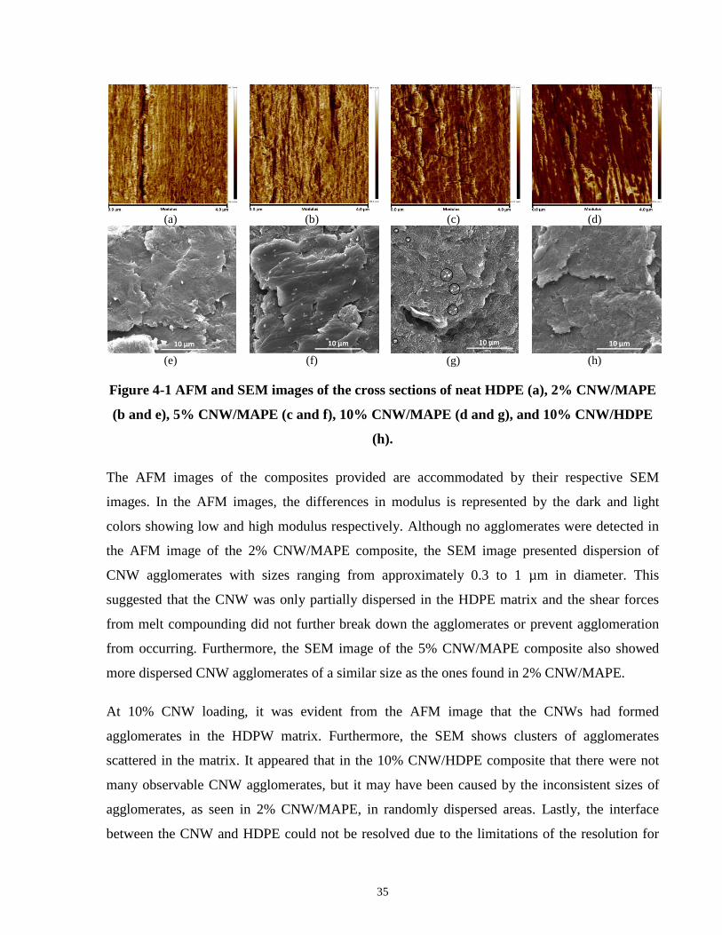
35
(a)
(b)
(c)
(d)
(e)
(f)
(g)
(h)
Figure 4-1 AFM and SEM images of the cross sections of neat HDPE (a), 2% CNW/MAPE
(b and e), 5% CNW/MAPE (c and f), 10% CNW/MAPE (d and g), and 10% CNW/HDPE
(h).
The AFM images of the composites provided are accommodated by their respective SEM
images. In the AFM images, the differences in modulus is represented by the dark and light
colors showing low and high modulus respectively. Although no agglomerates were detected in
the AFM image of the 2% CNW/MAPE composite, the SEM image presented dispersion of
CNW agglomerates with sizes ranging from approximately 0.3 to 1 µm in diameter. This
suggested that the CNW was only partially dispersed in the HDPE matrix and the shear forces
from melt compounding did not further break down the agglomerates or prevent agglomeration
from occurring. Furthermore, the SEM image of the 5% CNW/MAPE composite also showed
more dispersed CNW agglomerates of a similar size as the ones found in 2% CNW/MAPE.
At 10% CNW loading, it was evident from the AFM image that the CNWs had formed
agglomerates in the HDPW matrix. Furthermore, the SEM shows clusters of agglomerates
scattered in the matrix. It appeared that in the 10% CNW/HDPE composite that there were not
many observable CNW agglomerates, but it may have been caused by the inconsistent sizes of
agglomerates, as seen in 2% CNW/MAPE, in randomly dispersed areas. Lastly, the interface
between the CNW and HDPE could not be resolved due to the limitations of the resolution for

36
AFM and SEM. Therefore the CNW-HDPE compatibility was not evaluated between the
CNW/HDPE and CNW/MAPE composites based on the AFM and SEM images.
4.2.2 TGA and DSC of CNW/HDPE Composites
The thermal properties of CNW/HDPE and CNW/MAPE composites were examined the curves
attained from TGA and DSC. All the properties were determined and extracted using the TA
Universal Analysis software. These properties included the onset temperature of degradation,
enthalpy of fusion, and melting and crystallization temperatures. Additionally, the enthalpy of
fusion obtained from the first melting peak of the first DSC heating curve was used for further
calculation of the degree of crystallinity. The crystallinity was calculated using equation {3}
from section 3.2.2 and in combination with the enthalpy of fusion of 293 J/g of a 100%
crystalline polyethylene, which was obtained from the literature.[93] The TGA and DSC curves
used for analysis are presented below in Figure 4-2and Table 4-1.
(a)
0
10
20
30
40
50
60
70
80
90
100
25 140 255 370 485 600
Wei
ght C
hang
e [%
]
Temperature [°C]
HDPE1% CNW/HDPE2% CNW/HDPE5% CNW/HDPE10% CNW/HDPE
0102030405060708090
100
450 460 470 480 490 500

37
(b)
(c)
0
10
20
30
40
50
60
70
80
90
100
25 140 255 370 485 600
Wei
ght C
hang
e [%
]
Temperature [°C]
HDPE1% CNW/MAPE2% CNW/MAPE5% CNW/MAPE10% CNW/MAPE
0102030405060708090
100
450 460 470 480 490 500
-6
-4
-2
0
2
4
6
8
100 110 120 130 140 150
Hea
t Flo
w [W
/g],
Exo
Up
Temperature [°C]
HDPE1% CNW/HDPE2% CNW/HDPE5% CNW/HDPE10% CNW/HDPE

38
(d)
Figure 4-2 TGA curves for CNW/HDPE composites (a) and CNW/MAPE composites (b),
and heat-cool DSC curves for CNW/HDPE composites (c) and CNW/MAPE composites (d).
Table 4-1 Thermal properties of all the compositions obtained from the TGA and DSC
curves.
Sample Degradation Onset Temperature [°C]
Melting Temperature [°C]
Crystallization Temperature [°C] Crystallinity [%]
Neat HDPE 485.58 135.85 118.41 84.44
1% CNW/HDPE 487.19 131.51 120.38 67.32
2% CNW/HDPE 488.79 133.21 119.56 65.26
5% CNW/HDPE 472.37 132.84 120.63 62.33
10% CNW/HDPE 486.02 133.64 120.39 67.27
1% CNW/MAPE 485.65 136.09 118.14 64.26
2% CNW/MAPE 485.07 132.11 120.35 60.44
5% CNW/MAPE 485.14 132.84 121.07 61.68
10% CNW/MAPE 483.66 132.5 122.24 67.35
-6
-4
-2
0
2
4
6
8
100 110 120 130 140 150
Hea
t Flo
w [W
/g],
Exo
Up
Temperature [°C]
HDPE1% CNW/MAPE2% CNW/MAPE5% CNW/MAPE10% CNW/MAPE

39
The onset of degradation temperature between the pure HDPE, CNW/HDPE, and CNW/MAPE
composites did not show significant changes. For the CNW/HDPE composites, the degradation
temperature increased between 1 to 3°C by adding CNWs with the exception of a discrepancy at
5 wt% CNW/HDPE. Although there was a slight increase in the degradation temperature, a
greater percentage weight drop was observed from the onset of degradation temperature until
about 485°C when compared to neat HDPE. The weight drop was more significant at higher
CNW loading. Beyond 485°C, the degradation rate reduced with respect to the neat HDPE. In
contrast, when the coupling agent was added, the degradation temperature proceeded to decrease
with the addition of CNWs. Furthermore, the effect of degradation rate for the CNW/MAPE
composites showed the same trend as the CNW/HDPE composites, but not as prominent. This
trend can be explained by the CNWs being less thermally stable, which was also observed from
previous studies.[29, 30]
A decrease in the melting temperature was shown with by adding CNWs for both the
CNW/HDPE and CNW/MAPE composites. The introduction of CNW into the matrix disturbed
the uniformity of the polymer chains in the matrix and causing an increase in entropy resulting in
a lower melting temperature. On the other hand, the crystallization temperature increased with
CNW loading for both the composites with and without compatibilizer, which was expected
since CNWs can act as promoters for crystal nucleation. However, the degree of crystallinities of
all the compositions containing CNWs showed down to a 30% decrease when compared to the
neat HDPE. One of the possible reasons for this occurrence is the restricted crystal growth
caused by the enhanced filler-matrix interaction with a compatbilizer.[70] Moreover, due to the
inherently high crystallinity of HDPE, the addition of fillers can disrupt the uniformity of the
crystalline structures within the polymer.[75] At higher CNW loadings, the further reduction in
degree of crystallinity resulted from the increased amount of CNW and larger CNW
agglomerates impeding crystal growth. The addition of compatibilizer into the matrix did not
have a great impact on the thermal properties of the composites.
4.2.3 Water Vapor Transmission Test of CNW/HDPE Composites
The weight change, which was based on water loss, of the test dishes plotted over time for the
various CNW/HDPE and CNW/MAPE compositions are shown in Figure 4-3(a) and Figure
4-3(b). Comparisons were made with respect to neat HDPE, and CNW loadings and

40
compatibilizer effects. The equations {2} and {3} from section 3.2.3 were used to calculate the
WVT and WVP. The WVP of all the compositions plotted with respect to CNW loading is
shown in Figure 4-3(c).
(a)
(b)
-0.3
-0.25
-0.2
-0.15
-0.1
-0.05
0
0 50 100 150 200 250 300 350 400 450
Wei
ght C
hang
e [g
]
Time [hours]
HDPE1% CNW/HDPE2% CNW/HDPE5% CNW/HDPE10% CNW/HDPE
-0.3
-0.25
-0.2
-0.15
-0.1
-0.05
0
0 50 100 150 200 250 300 350 400 450
Wei
ght C
hang
e [g
]
Time [hours]
HDPE1% CNW/MAPE2% CNW/MAPE5% CNW/MAPE10% CNW/MAPE

41
(c)
Figure 4-3 Weight change vs. time curves of CNW/HDPE (a) and CNW/MAPE (b)
composites, and WVP vs. CNW loading of CNW/HDPE and CNW/MAPE composites.
The slope of the linear regressions from the water loss to time plots show the rate of water
diffusion through each composite film. A steeper slope indicates a higher water transmission
through the film and vice versa. In many cases, the incorporation of fillers in a polymer matrix
helps to decrease water vapor permeance since it promotes crystallinity and creates a more
tortuous path for the water vapor molecules.[40] However, even though the CNWs showed
dispersion within the HDPE matrix, an increase in WVP was observed with the addition of
CNWs. One main reason for this trend was the decrease in the crystallinities of the composites,
which were determined earlier by DSC. The major drop in crystallinity when the CNWs were
added to the HDPE allowed for more amophous regions for the water molecules to easily travel
through. Despite a decrease in crystallinity of up to 25%, the water vapor permeance at low
CNW loadings did not differ by too much when compared to neat HDPE. This signified a
countering effect of the CNWs helping to block the path of the water vapor. Another indication
of this effect was at higher CNW loadings, where a slight decrease in WVP was observed from
5% to 10% CNW loading. This same trend was observed for the CNW/MAPE composites.
0
1
2
3
4
5
6
7
8
9
10
0 2 4 6 8 10 12
WVP
[x10
-9·g
·s-1
·m-2
·Pa-
1 ]
Chitin Loading [%]
HDPECNW/HDPECNW/MAPE

42
It was proposed that the addition of compatibilizer should help reduce the water vapor
permeance by enhancing the filler-matrix interaction and minimizing interfacial gaps, which can
in turn allow water to diffuse through easier. Nevertheless, the water vapor permeance of the
CNW/MAPE composites showed a an even greater increase than the CNW/HDPE composites.
On top of the reduction in crystallinity from the CNWs, a further decrease in crystallinity was
suspected as a result of the compatibilizer, which was explained in the previous section.
Aside from the crystallinity of the composites, the fillers and compatibilizer themselves have
possible effects on the WVP. Since the CNWs used were water sensitive and can absorb water,
this could have helped to slow down the water loss as the water vapor passed through the film.
This was supported by the composites at the highest CNW loading in this study, but the WVP of
these composites were still higher than the neat HDPE. Moreover, the compatibilizer also has
hydrophilic properties, so it could have contributed to the reducing the mobility of the water.
Lastly, the compatibilizer should have improved the interaction between the CNWs and the
HDPE matrix in order to prevent voids at the interface to decrease water transport. Although
these factors could have potentially minimized the WVP, they were not sufficient enough to
overcome the crystallinity effects.
4.2.4 Tensile Test of CNW/HDPE Composites
The elastic modulus, ultimate tensile strength, and elongation strain at break of the CNW/HDPE
and CNW/MAPE composites at different CNW loading were extracted from stress-strain curves
and are displayed in Figure 4-4.

43
(a)
(b)
600
700
800
900
1000
1100
1200
1300
1400
1500
1600
0 2 4 6 8 10 12
Elas
tic M
odul
us [M
Pa]
Chitin Loading [wt %]
HDPECNW/HDPECNW/MAPE
25
26
27
28
29
30
31
32
33
34
35
0 2 4 6 8 10 12
Ulti
mat
e Te
nsile
Str
engt
h [M
Pa]
Chitin Loading [wt %]
HDPECNW/HDPECNW/MAPE

44
(c)
Figure 4-4 Tensile properties of the CNW/HDPE and CNW/MAPE composites based on
elastic modulus (a), ultimate tensile strength (b), and elongation strain at break (c).
When adding a rigid filler into a polymer matrix, the elastic modulus usually increases since the
stiff filler has a higher modulus itself.[96] So as expected, the elastic modulus increase up to
20% and 15% by adding CNWs for both the CNW/HDPE and CNW/MAPE composites
respectively compared to the neat HDPE. Moreover, the partially dispersed CNWs observe from
the cross sectional images of the composites contributed to the increase in elastic modulus. The
maximum elastic modulus for both sets of composites occurred at 10 wt%, which was the
maximum CNW loading in this study. As a result, an even higher elastic modulus could
potentially be found with CNW loading greater than 10 wt%. The addition of a compatibilizer to
the composite did not show enhancements in its elastic modulus when compared to the
composites without the compatibilizer. This may have been a caused by the poor mechanical
properties of the compatibilizer that had transferred into the composite. Therefore the
compatibilizing effects was not as pronounced.
On the other hand, the ultimate tensile strength of both sets of composites decreased with the
addition of CNW except at 10 wt% CNW loading when compared with neat HDPE. Two
0
0.05
0.1
0.15
0.2
0.25
0.3
0.35
0.4
0 2 4 6 8 10 12
Elon
gatio
n St
rain
at B
reak
[%]
Chitin Loading [wt %]
HDPECNW/HDPECNW/MAPE

45
contributing factors for this decrease can be explained by the lack of reinforcement between the
CNW and the HDPE, and the density of the composites. The former is relatively straightforward
since the absence of filler-matrix interaction can prevent stress transfer from the HDPE to CNW
and result in interfacial gaps causing stress concentrations for early failure. As for the former
reasoning, although not investigated in this study, the density of the composites could have
caused the reduction in ultimate tensile strength. This was as a result of the drop in density of the
composites due to the lowering of the degree of crystallinity with the addition of CNWs and the
addition of a compatibilizer with a lower density. Since crystallinity is related to density because
polymer chains in the crystalline region can pack better than in the amorphous region, therefore
it was predicted that the density had decreased as well, which can affect the decrease in ultimate
tensile strength. However, the effects of compatibilizer on the reinforcement of the composite
was observed as the ultimate tensile strength of the CNW/MAPE composites were slightly
higher than the CNW/HDPE composites.
A gradual reduction in the elongation strain at break was seen with the CNW/HDPE composites
as the amount of CNW loading increased. The elongation strain at break was also continuously
lower than that of neat HDPE. In contrast, the addition of the compatibilizer showed a higher
elongation strain at break at 1 and 2 wt% CNW loadings and then proceeded to decrease with
increasing CNW loadings with respect to neat HDPE. Overall, the CNW/MAPE composites
showed a greater elongation strain at break compared to CNW/HDPE, which suggested that the
compatibilizer exhibited a plasticizing effect enabling the composite to become more flexible.
This also supported the slight decrease observed in elastic modulus since the reduction in
crystallinity allows for the ease of access of diluents into the amorphous regions to lower the
stiffness of the composites.
4.2.5 Rheology Test of CNW/HDPE Composites
Rheological properties of the CNW/HDPE and CNW/MAPE composites were evaluated using a
parallel plate geometry with an applied shear force over a range of frequencies. The storage
modulus and complex viscosity results are shown in Figure 4-5.

46
(a)
(b)
5
50
500
5000
50000
0.1 1 10 100 1000
Stor
age
Mod
ulus
[Pa]
Frequency [rad/s]
HDPE1% CNW/HDPE2% CNW/HDPE5% CNW/HDPE10% CNW/HDPE
5
50
500
5000
50000
0.1 1 10 100 1000
Stor
age
Mod
ulus
[Pa]
Frequency [rad/s]
HDPE1% CNW/MAPE2% CNW/MAPE5% CNW/MAPE10% CNW/MAPE

47
(c)
(d)
Figure 4-5 Storage modulus and complex viscosity of CNW/HDPE (a and c) and
CNW/MAPE (b and d) composites with respect to frequency.
300
3000
0.1 1 10 100 1000
Com
plex
Vis
cosi
ty [P
a·s]
Frequency [rad/s]
HDPE1% CNW/HDPE2% CNW/HDPE5% CNW/HDPE10% CNW/HDPE
300
3000
0.1 1 10 100 1000
Com
plex
Vis
cosi
ty [P
a·s]
Frequency [rad/s]
HDPE1% CNW/MAPE2% CNW/MAPE5% CNW/MAPE10% CNW/MAPE

48
In theory, the reinforcing effect of fillers in a polymer matrix should reveal an increase in storage
modulus and complex viscosity especially at low frequencies.[97] This is because the
dependence of these properties at low frequencies decline as the compatibility between the filler
and matrix improve. Therefore, the lack of improvement in the storage modulus of the
CNW/HDPE was expected since CNW is not compatible with each other due to their differences
in polarity and the ultimate tensile strength results from the previous section did not increase.
Further analysis of the CNW/MAPE composites showed no improvements in the storage
modulus either. The reason for this was due to the inefficiency of the compatibilizer in enhancing
the CNW-HDPE interaction and the compatibilizer exhibiting a plasticizing behavior from the
mechanical properties. Both of these factors will cause a decrease in the storage modulus
because it enables polymer chains to flow more freely past each other. This was reminiscent of
the behavior observed in previous studies on CNW/PLA composites.[29, 30]
Similar to the storage modulus, the complex viscosity is expected to increase with filler addition
given that successful enhancement of the filler and polymer matrix interaction is achieved.
However, for the same reasons as the minor changes in storage modulus, the complex viscosity
did not differ by a lot either. Although a small increase was observed for the CNW/HDPE
composites, it was suspected as a result of the dispersion of the small CNW agglomerates in the
HDPE. The CNW/MAPE composites had a further reduction in the complex viscosity, which
was believed to be as a result of the compatibilizer . Overall, the rheological measurements were
consistent with the observed mechanical properties of the composites.
4.3 Summary This paper examined the morphological, thermal, water barrier, mechanical, and rheological
properties of CNW/HDPE and CNW/MAPE composites at different CNW loadings processed
through melt compounding. The purpose was to investigate the possibility in using CNW/HDPE
composites to outperform existing solutions of composites of nanoclay and carbon nanofillers in
HDPE for mainly mechanical and water barrier properties. The addition of CNW promoted
crystal nucleation and increased the crystallization temperature, but decreased in melting
temperature and caused the composite to become less thermally stable. Despite an observable
dispersion of CNWs in HDPE and increase in elastic modulus, the compatibility between the
filler and matrix remained an issue and caused a drop in ultimate tensile strength and water vapor

49
resistance. This was verified by the storage modulus and complex viscosity of the composites,
which were determined to have a similar trend compared to neat HDPE over a range of
frequencies, signifying poor compatibility between the CNW and HDPE. Furthermore, using
CNW in HDPE restricted the crystal growth in the composites and reduced its crystallinity,
which affected the ability of the composite to resist water diffusion. At low CNW loading, the
crystallinity of the composite seem to have countered the effects of the fillers for the water
barrier properties. On the other hand, at higher CNW loading, the effects of the fillers on the
improving water barrier properties became more prominent. Based on the results from this study,
it is evident that further investigation is required in optimizing processing methods to minimize
CNW agglomeration and maintain or increase the crystallinity of the HDPE composites.
Considerations need to be taken to examine the water absorption and oxygen barrier properties of
the composites.

50
Chapter 5 Chitin Nanowhisker/Polyolefin Composite Masterbatches
This study uses a two step approach in processing CNW/polymer composites to investigate the
masterbatch dilution of these composites in two different polymer systems, which includes PP
and HDPE. Examination of their morphological, thermal, water barrier, mechanical, and
rheological properties will help evaluate its the feasibility in producing diluted composites with
enhanced properties for industrial scale processing. Not only can chitin and its derivatives
substitute the use of inorganic fillers, it also has the edge over cellulose in potentially replacing
hazardous metallic fillers used in medical applications for antimicrobial properties.[98]
Moreover, water barrier is an integral material property for packaging applications that many
studies lack to examine.
5.1 Materials and Methods for Fabrication of Masterbatch and Diluted CNW/PP and CNW/HDPE Composites
5.1.1 Materials for Fabrication of CNW/PP and CNW/HDPE Composites
The CNW provided by BOCO Technology Inc. had an aspect ratio (L/W) and density of
approximately 20-50 and 1.45 g·cm-3 respectively. It was used as the filler for preparing the
composite masterbatch along with homopolymers of PP (ExxonMobil AchieveTM 3854) and
HDPE (ExxonMobilTM HDPE HD 6908), and their respective compatibilizers of maleated PP
(EastmanTM G-3003 Polymer) and maleated HDPE (Westlake Epolene® C-26). The
homopolymers of PP and HDPE had densities of 0.9 g·cm-3 and 0.965 g·cm-3 respectively.
5.1.2 Preparation of Masterbatch and Dilution of CNW/PP and CNW/HDPE Composites
CNW/PP and CNW/HDPE composites were prepared by a two stage melt compounding process
with a co-rotating twin screw micro compounder (DSM Xplore® MC 15). In the first stage, two
sets of masterbatches, with and without compatibilizer, of the PP and HDPE composites at a 10
wt% CNW loading were processed in the compounder operating at 170°C and 200 rpm. The
masterbatches were then processed again under the same conditions but diluted using their

51
respective base polymers to produce composites containing 1 and 2 wt% CNW loading. The four
sets of composites investigated in this study are denoted by CNW/PP and CNW/MAPP for the
PP composites, and CNW/HDPE and CNW/MAPE for the HDPE composites.
The composites were further processed using compression molding and injection molding to
prepare specimens for testing. A hydraulic hot press (Carver, Inc.) operating at 180°C and 1000
psi was used to create composite films with less than 200 µm in thickness for water barrier
testing, and disks with 25 mm in diameter and 1.1 mm in thickness for rheological testing. On
the other hand a micro injection molding machine (DSM Xplore® IM 5.5) operating at 180°C
and 100 psi was used to produce type IV tensile testing specimens for mechanical testing.
5.1.3 Characterization of Masterbatch and Diluted CNW/PP and CNW/HDPE Composites
5.1.3.1 Morphology
Analysis of the cross sectional morphology of the masterbatch and diluted CNW/PP and
CNW/HDPE composites were performed by scanning electron microscopy (SEM) using the
Quanta FEG 250 ESEM (FEITM). The samples for imaging were prepared by nitrogen fracturing
and gold sputtering to prevent the sample from charging and being damaged from the electron
beam.
5.1.3.2 Thermal Behavior
The thermal degradation, crystallization, and melting temperature of the diluted CNW/PP and
CNW/HDPE composites were determined using thermogravimetric analysis (TGA) and
differential scanning calorimetry (DSC). TGA Q50 (TA Instruments) was used for thermal
degradation analysis under nitrogen conditions at a temperature ramp of 20°C/min. from room
temperature (25°C) to 600°C. The DSC Q2000 (TA Instruments) was used for melting and
crystallization analysis under nitrogen conditions through a heat-cool cycle between room
temperature (25°C) to 200°C at a rate of 10°C/min..
5.1.3.3 Water Vapor Barrier
Diluted CNW/PP and CNW/HDPE composite films prepared from compression molding were
mounted onto a test setup, which contained water with a fixed initial height relative to the film.
52
The test setups were prepared based on the water method stated in the ASTM E96 standard and
for this study were kept in a FormaTM Series II Water Jacket CO2 incubator (Thermo
ScientificTM) under constant temperature and humidity conditions of 50°C and 0% RH
respectively. They were also weighed at least 7 times over a period of one to two and a half
weeks to record its changes in weight. An average of three films for each composition were
taken into account to ensure consistency of the results.
5.1.3.4 Mechanical Behavior
Mechanical properties of the composites were measured through uniaxial tensile testing using the
Microtester 5848 (Instron) machine to obtain stress-strain curves. The composite samples were
prepared by injection molding to create Type IV specimens specified by ASTM D638 standards.
Six specimens for each composition were tested and their ultimate tensile strengths, elastic
moduli, and elongation strains at break were averaged for analysis.
5.1.3.5 Rheological Behavior
Rheological properties, including storage modulus and complex viscosity, were determined using
a parallel plate geometry fixture for the ARES rheometer (TA instruments). In making sure that
the tests were performed within the linear viscoelastic region of the composites, an initial strain
sweep test was ran to obtain a proper strain rate to be used for running the dynamic frequency
sweep tests. Three samples for all the compositions were used to carry out the dynamic
frequency sweep tests with the operating temperature, strain rate, and frequency range of 160°C,
6%, and 0.1 to 200 rad/s respectively.
5.2 Results and Discussion of Masterbatch and Diluted CNW/PP and CNW/HDPE Composites
5.2.1 SEM Morphology of Masterbatch and Diluted CNW/PP and CNW/HDPE Composites
Cross sections of the masterbatch and diluted CNW/PP and CNW/HDPE composites taken from
SEM are shown below in Figure 5-1. The morphology and CNW dispersion in the polymer
matrices can be observed from these images.

53
(a)
(b)
(c)
(d)
(e)
(f)
Figure 5-1 SEM images of 10% CNW/MAPP (a), 2% diluted CNW/MAPP (b and c), 10%
CNW/HDPE (d), and 2% diluted CNW/MAPE (e and f) composites.
A well CNW dispersion was observed in the 10% CNW/MAPP masterbatch but with notable
agglomeration. After the dilution process, the size of the agglomerates did not reduce in size as
shown in the morphology of the 2% diluted CNW/MAPP composites in Figure 5-1(b).
Furthermore, a closer magnification of the 2% diluted CNW/MAPP composite revealed the
existence of CNW agglomerates up to the size of 1 μm as shown in Figure 5-1(c). Operating at a
faster screw speed could potentially reduce the size of the agglomerates as identified by a
previous study, but the high shear can also cause degradation of the CNWs.[78] Although, the
CNW agglomerates are shown to be relatively well dispersed in the PP matrix, it was not
representative of the bulk morphology of the material as localized dispersion of the CNWs was
observed. This could have been as a result of reduced interaction between the slight hydrophilic
nature of CNW/MAPP masterbatch not being able to well disperse within the hydrophobic PP
matrix.[80]
In contrast, a well dispersion of much smaller agglomerates were seen in the 10% CNW/HDPE
masterbatch. Moreover, the relative sizes of the agglomerates were also retained after the
dilution process as shown in Figure 5-1(f and g). The average sizes of the agglomerates were
identified to range from 30 to 100 nm. Since the diameter of the CNWs are in the range of 10 to
20 nm, it was possible that some of the particles observed in the SEM images are cross sections
of the CNWs. It was also observed in Figure 5-1(g) that there are regions where there were

54
higher densities of CNWs, so the dispersion of the CNWs were not uniform throughout the
whole matrix as explained previously with the diluted CNW/MAPP composites.
5.2.2 TGA and DSC of Diluted CNW/PP and CNW/HDPE Composites
TGA and DSC curves obtained from thermal testing were analyzed using the TA Universal
Analysis software and are shown in Figure 5-2. The software helped determine the onset
temperature of thermal degradation, crystallization temperature, and melting temperature of the
diluted CNW/PP and CNW/HDPE composites. From the first DSC heating curve, the enthalpy
of fusion measured by the software was attained for the further calculation of the degree of
crystallinity of the composites using equation {1} from section 3.2.2.
(a)
0
10
20
30
40
50
60
70
80
90
100
25 140 255 370 485 600
Wei
ght C
hang
e [%
]
Temperature [°C]
Neat PP1% Diluted CNW/PP2% Diluted CNW/PP1% Diluted CNW/MAPP2% Diluted CNW/MAPP
0102030405060708090
100
450 460 470 480 490 500

55
(b)
(c)
0
10
20
30
40
50
60
70
80
90
100
25 140 255 370 485 600
Wei
ght C
hang
e [%
]
Temperature [°C]
Neat HDPE1% Diluted CNW/HDPE2% Diluted CNW/HDPE1% Diluted CNW/MAPE2% Diluted CNW/MAPE
0102030405060708090
100
450 460 470 480 490 500
-2
-1
0
1
2
3
4
80 100 120 140 160 180
Hea
t Flo
w [W
/g],
Exo
Up
Temperature [°C]
Neat PP1% Diluted CNW/PP2% Diluted CNW/PP1% Diluted CNW/MAPP2% Diluted CNW/MAPP
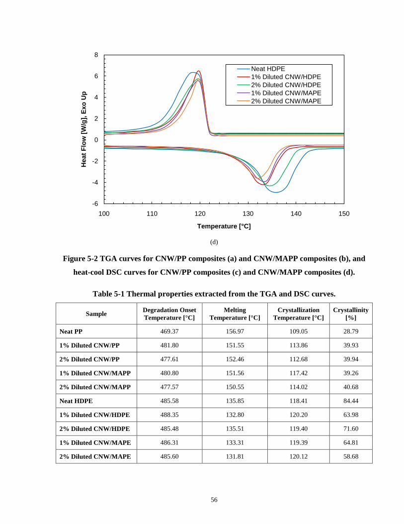
56
(d)
Figure 5-2 TGA curves for CNW/PP composites (a) and CNW/MAPP composites (b), and
heat-cool DSC curves for CNW/PP composites (c) and CNW/MAPP composites (d).
Table 5-1 Thermal properties extracted from the TGA and DSC curves.
Sample Degradation Onset Temperature [°C]
Melting Temperature [°C]
Crystallization Temperature [°C]
Crystallinity [%]
Neat PP 469.37 156.97 109.05 28.79
1% Diluted CNW/PP 481.80 151.55 113.86 39.93
2% Diluted CNW/PP 477.61 152.46 112.68 39.94
1% Diluted CNW/MAPP 480.80 151.56 117.42 39.26
2% Diluted CNW/MAPP 477.57 150.55 114.02 40.68
Neat HDPE 485.58 135.85 118.41 84.44
1% Diluted CNW/HDPE 488.35 132.80 120.20 63.98
2% Diluted CNW/HDPE 485.48 135.51 119.40 71.60
1% Diluted CNW/MAPE 486.31 133.31 119.39 64.81
2% Diluted CNW/MAPE 485.60 131.81 120.12 58.68
-6
-4
-2
0
2
4
6
8
100 110 120 130 140 150
Hea
t Flo
w [W
/g],
Exo
Up
Temperature [°C]
Neat HDPE1% Diluted CNW/HDPE2% Diluted CNW/HDPE1% Diluted CNW/MAPE2% Diluted CNW/MAPE
57
The thermal stabilities of the diluted CNW/PP composites were improved with CNW since the
onset temperature of degradation were shown to be higher than neat PP. Furthermore, the rate of
degradation was also reduced, with the exception of a discrepancy at 1% diluted CNW/PP
composite, which showed a faster rate of degradation. A slower degradation rate can be
explained by the CNWs acting as a source of material to conduct heat. Similarly, the thermal
stability of the diluted CNW/HDPE composites also improved slightly, but not as pronounced as
observed with CNW/PP composites. The addition of a compatibilizer showed no effects on the
thermal degradation temperature since the curves corresponding to a particular diluted CNW
loading composition had close overlaps with each other.
A decrease in melting temperature was discovered upon the DSC analysis of both the diluted
CNW/PP and CNW/HDPE composites relative to the neat base polymers. This decrease can be
explained by the CNWs disrupting polymer chain movement and encouraging the formation of
randomly oriented structures. As a result, the entropy of the composite system increased and the
melting temperature of the composites were reduced. Moreover, the introduction of CNW into
PP and HDPE showed an increase in crystallization temperature relative to the neat polymer
itself. This was be explained by the known concept that fillers in a polymer can induce crystal
nucleating effects.[99]
However, a significant difference in the effects of CNW on the degree of crystallinity between
the two polymer systems was observed. For the diluted CNW/PP composites, there was an
increase of at least 10% in crystallinity when compared to neat PP. On the other hand, there was
a decrease of 20% or more in crystallinity for the diluted CNW/HDPE composites compared to
neat HDPE. In both polymer systems, the CNWs promoted crystallization as mentioned earlier,
however, crystal growth was identified as the limiting factor accounting for their differences
under the non-isothermal conditions of this study.[77] This suggested that the CNWs had
different impact on the crystallization of PP and HDPE since all the composites were processed
in the same manner. In this study, the PP used had a much lower initial crystallinity than the
HDPE, therefore the CNW allowed for more crystal formation in PP with minimal restriction in
crystal growth. On the other hand, the HDPE used had a higher initial crystallinity, therefore the
CNW greatly suppressed free volume and mobility of the polymer chains to minimize their
ability in forming ordered crystals.[100] For both polymer systems, the addition of a
compatibilizer in the composites showed minimal effects on its overall thermal properties.

58
5.2.3 Water Barrier Properties of Diluted CNW/PP and CNW/HDPE Composites
The water barrier properties of the diluted composites were compared with their respective pure
base polymer matrix. From a linear fit of the weight loss due to water permeation through the
film over time, the water vapor transmission (WVT) of the composites could be attained. The
water vapor permeance (WVP) was also calculated using to account for the temperature and
humidity conditions during the test. Both values were evaluated based on ASTM E96 standard.
These values determined helped express the rate in which water diffused through the composite
films. The WVP of the diluted composites were plotted with respect to CNW loading and are
presented in Figure 5-3.
(a)
0
0.5
1
1.5
2
2.5
3
3.5
4
4.5
0 1 2 10
WVP
[x10
-8·g
·s-1
·m-2
·Pa-
1 ]
Chitin Loading [wt %]
Neat PPCNW/PPCNW/MAPPDiluted CNW/PPDiluted CNW/MAPP

59
(b)
Figure 5-3 WVP vs. CNW loading of CNW/PP and CNW/MAPP (a), and CNW/HDPE and
CNW/MAPE (b) composites.
The WVP of diluted CNW/PP composites was observed to be lower when compared to neat PP
as a result of the increase in crystallinity and the CNWs providing tortuous path for the water
molecules. The crystallinity of a polymer has an impact on its water barrier properties because of
the packing of the crystal structures that can stop water vapor from penetrating through it.[47] It
was believed that the diluted CNW/MAPP would have an even lower WVP due to the enhanced
filler-matrix interaction to mitigate water travelling through poor interfaces. However, the WVP
of diluted CNW/MAPP composites were higher than the diluted CNW/PP composites but still
below neat PP. Although a better filler-matrix interface with the compatibilizer may have
existed, a previous study had concluded that the incompatibilities between the masterbatch and
the polymer for dilution can prevent good dispersion.[80] In this study, the CNW/MAPP
masterbatch, which had a more polar behavior, combined with the nonpolar PP could have
potentially reduced the proper dispersion of the CNW in the composite causing localized areas of
dispersion from the masterbatch. The dispersion of CNW is an important factor in reducing
WVP because a better the dispersion covers a larger surface area of obstacles in impeding the
0
1
2
3
4
5
6
7
8
9
10
0 1 2 10
WVP
[x10
-9·g
·s-1
·m-2
·Pa-
1 ]
Chitin Loading [wt %]
Neat HDPECNW/HDPECNW/MAPEDiluted CNW/HDPEDiluted CNW/MAPE

60
diffusion of water across the composites. An optimal WVP was observed at 1% and 2% for the
diluted CNW/PP and CNW/MAPP composites respectively. Despite diluted CNW/PP and
CNW/MAPP composites showing a lower WVP than neat PP, it was still much higher in
comparison to the as compounded CNW/PP and CNW/MAPP composites from Chapter 3 even
though they had a slightly higher degree of crystallinity. This was due to the residual
agglomerates that were not further broken down after the dilution process on top of the
suboptimal CNW dispersion in the PP matrix.
On the other hand, a higher WVP was seen for the diluted CNW/HDPE composites compared to
neat HDPE due to the significant decrease in crystallinity, which dominated the effects of the
CNWs as the source of blocking agent for water vapor diffusion. The loosely packed amorphous
structures in the polymer allowed water to move freely through the composite films. Similar with
the diluted CNW/MAPP composites, the diluted CNW/MAPE composites also had a higher
WVP compared to the diluted CNW/HDPE at 1% CNW loading, but was slightly lower at 2%
CNW loading. As with the diluted CNW/MAPP composites, the opposition in the polarities of
the CNW/MAPE masterbatch and HDPE could have hindered the dispersion of the CNWs.
However, the 2% diluted CNW/MAPE composite was not expected to have a lower WVP than
the 2% diluted CNW/HDPE composite since it had a much lower crystallinity. Therefore it was
suggested that the compatibilizer had some influence on lowering the WVP. Furthermore, the
diluted CNW/HDPE and CNW/MAPE composites had a higher WVP when compared to the as
compounded CNW/HDPE and CNW/MAPE composites. This was consistent with what was
observed earlier with the diluted CNW/PP composites, therefore it was also suspected that the
lack of proper dispersion contributed to the increase in WVP.
5.2.4 Tensile Testing of Diluted CNW/PP and CNW/HDPE Composites
Three main tensile properties, which includes elastic modulus, ultimate tensile strength,
elongation strain at break, of the diluted CNW/PP and CNW/HDPE composites will be analyzed
in this section. They have been plotted with respect to their compositions and are displayed in
Figure 5-4.

61
(a)
(b)
600
700
800
900
1000
1100
1200
1300
1400
1500
1600
0 1 2 10
Elas
tic M
odul
us [M
Pa]
Chitin Loading [wt %]
Neat PPCNW/PPCNW/MAPPDiluted CNW/PPDiluted CNW/MAPP
600
700
800
900
1000
1100
1200
1300
1400
1500
1600
0 1 2 10
Elas
tic M
odul
us [M
Pa]
Chitin Loading [wt %]
Neat HDPECNW/HDPECNW/MAPEDiluted CNW/HDPEDiluted CNW/MAPE

62
(c)
(d)
20
25
30
35
40
45
0 1 2 10
Ulti
mat
e Te
nsile
Str
engt
h [M
Pa]
Chitin Loading [wt %]
Neat PPCNW/PPCNW/MAPPDiluted CNW/PPDiluted CNW/MAPP
20
22
24
26
28
30
32
34
36
38
40
0 1 2 10
Ulti
mat
e Te
nsile
Str
engt
h [M
Pa]
Chitin Loading [wt %]
Neat HDPECNW/HDPECNW/MAPEDiluted CNW/HDPEDiluted CNW/MAPE

63
(e)
(f)
Figure 5-4 Elastic modulus (a & b), ultimate tensile strength (c & d), and elongation strain
at break (e & f) of CNW/PP, CNW/MAPP, CNW/HDPE and CNW/MAPE composites.
0
0.5
1
1.5
2
2.5
0 1 2 10
Elon
gatio
n St
rain
at B
reak
[%]
Chitin Loading [wt %]
Neat PPCNW/PPCNW/MAPPDiluted CNW/PPDiluted CNW/MAPP
0
0.05
0.1
0.15
0.2
0.25
0.3
0.35
0.4
0.45
0 1 2 10
Elon
gatio
n St
rain
at B
reak
[%]
Chitin Loading [wt %]
Neat HDPECNW/HDPECNW/MAPEDiluted CNW/HDPEDiluted CNW/MAPE

64
For the diluted CNW/PP composites, the elastic moduli and ultimate tensile strengths were
observed to be similar to neat PP and without much improvement, though the elastic modulus at
2% CNW loading had a much greater increase due to the rigidity of the CNWs. This showed
evidence that there was little to no reinforcement between the CNW and PP. Moreover, the
CNW caused a slight increase in elongation strain at break at 1% CNW loading but then a
dramatic drop occurred at 2% CNW loading. This suggested that the lack of reinforcement and
agglomerates within the matrix induced localized stress for early failure. In contrast, despite the
WVP of diluted CNW/MAPP composites being higher than the diluted CNW/PP composites due
to its suboptimal CNW dispersion within the matrix, the addition of a compatibilizer to the
composite resulted in a greater increase in elastic modulus and ultimate tensile strength than the
diluted CNW/PP composites. This was explained by the reinforcing effect that the compatibilizer
exhibited in enhancing the interaction between the CNW and PP. However, the elastic modulus
and ultimate tensile strength did not further increase after 1% CNW loading, therefore it was
proposed that the optimal properties occurred at 1% CNW loading or less, but lower weight
percentages were not tested in this study. By comparing the diluted and as compounded
CNW/PP and CNW/MAPP composites, the as compounded composites had slightly better
mechanical properties as expected due to the existence of larger CNW agglomerates mentioned
earlier.
As for the diluted CNW/HDPE composites, although they displayed smaller agglomerates that
were better dispersed than in PP and has a notable increase in elastic modulus as a result of the
incorporation of a stiff filler, but its ultimate tensile strength and elongation strain at break did
not show significant changes compared to neat HDPE. Even with the addition of a
compatibilizer, the elastic modulus was much lower compared to the diluted CNW/HDPE
composites though still higher than the neat HDPE. Furthermore, the diluted CNW/MAPE
composites also had the same trend where its ultimate tensile strength and elongation strain at
break remained relatively the same as neat HDPE. One possible explanation for this behavior
may have been caused by the substantial drop in crystallinity, which resulted in return can affect
the density and tensile strength of the composite. Therefore, it was believed that the crystallinity
effects had counteracted any potential reinforcement that the compatibilizer may have expressed.
The reduction in the crystallinity when adding fillers to HDPE has been a phenomenon observed
by many other studies.[101-103] It has also shown very minimal improvements in mechanical

65
properties as was observed in this study. As for the comparisons between the diluted and as
compounded CNW/HDPE and CNW/MAPE composites, the mechanical properties were
consistent between the two. This may have been due to the smaller agglomerates seen in the
CNW/HDPE composite masterbatches, therefore it had a less effect on the mechanical properties
after dilution.
5.2.5 Rheology of Diluted CNW/PP and CNW/HDPE Composites
The storage modulus and complex viscosity measurements of the diluted CNW/PP and
CNW/HDPE composites with respect to a range of frequencies were graphed and depicted in
Figure 5-5.
(a)
0.1
1
10
100
1000
10000
100000
0.1 1 10 100 1000
Stor
age
Mod
ulus
[Pa]
Frequency [rad/s]
Neat PP1% Diluted CNW/PP2% Diluted CNW/PP1% Diluted CNW/MAPP2% Diluted CNW/MAPP

66
(b)
(c)
1
10
100
1000
10000
100000
0.1 1 10 100 1000
Stor
age
Mod
ulus
[Pa]
Frequency [rad/s]
Neat HDPE1% Diluted CNW/HDPE2% Diluted CNW/HDPE1% Diluted CNW/MAPE2% Diluted CNW/MAPE
200
2000
0.1 1 10 100 1000
Com
plex
Vis
cosi
ty [P
a·s]
Frequency [rad/s]
Neat PP1% Diluted CNW/PP2% Diluted CNW/PP1% Diluted CNW/MAPP2% Diluted CNW/MAPP

67
(d)
Figure 5-5 Storage modulus (a and b) and complex viscosity (c and d) of diluted CNW/PP,
CNW/MAPP, CNW/HDPE, and CNW/MAPE composites.
The storage modulus and complex viscosity at low frequencies were expected to increase with
the addition of a filler and compatibilizer due to the reduced dependency on the interaction
between the filler and matrix at those frequencies.[97] The storage moduli and complex
viscosities of the diluted CNW/PP composites at low frequencies were similar to neat PP, which
was expected since the concentration of fillers were relatively low, the CNW dispersion observed
form the SEM images were not optimal, and the poor interfacial interaction between CNW and
PP. However, a decrease in the storage moduli and complex viscosity was unexpected since there
were improvements in mechanical properties. In order to evaluate this result, it was possible that
the incompatibility between the compatibilized masterbatch with the neat PP, as mentioned
earlier, could have caused this reduction in addition with the CNW agglomerates.
On the other hand, a slight increase in the storage moduli and complex viscosities of the diluted
CNW/HDPE composites was seen at low frequencies. The increase in these properties can be
explained by the better dispersion of CNWs providing a greater specific surface area for
hydrodynamic interactions between them.[79] This was consistent with the improvement in
100
1000
10000
0.1 1 10 100 1000
Com
plex
Vis
cosi
ty [P
a·s]
Frequency [rads]
Neat HDPE1% Diluted CNW/HDPE2% Diluted CNW/HDPE1% Diluted CNW/MAPE2% Diluted CNW/MAPE

68
elastic modulus. However, similar with the diluted CNW/MAPP composites, the CNW/MAPE
composites had a decrease in both storage modulus and complex viscosity even though they were
observed to have a better CNW dispersion. The issue with incompatibilities between the
masterbatch and the neat HDPE was also an applicable explanation for this case. Although no
significant enhancements in the interactions between the CNW and polymers were observed
based on the rheological behaviors presented, the crystallinity effects were not accounted for
since the composites were tested in a molten state.
5.3 Summary
The process of masterbatch dilution was tested in this section with the use of CNWs in PP and
HDPE by melt compounding. Morphological, thermal, water barrier, mechanical, and
rheological analysis were performed to evaluate quality of the diluted composites. The focus of
this study was to examine if masterbatch dilution is a suitable technique for the future
development of biocomposite materials to minimize the current use of carbon and inorganic filler
based polymer composites for industrial packaging applications. With the addition of CNW to
PP, an enhancement in thermal stability, crystallinity, elastic modulus, tensile strength, and water
barrier properties relative to neat PP were observed. Even though the addition of a compatibilizer
showed some hindrance in the dispersion of the CNWs causing slight reductions in water barrier
properties, it is proposed that the dilution process can be further optimized for better dispersion.
In contrast, the addition of CNWs to HDPE had opposite effects where only slight improvements
in thermal stability and mechanical properties were achieved, but a decrease in crystallinity and
water barrier properties was also observed. Similar with the diluted CNW/MAPP composites,
dispersion of the diluted CNW/MAPE still remained a challenge, but the CNW agglomerate
sizes observed were much smaller. The mechanical and water barrier properties of both
composite systems were found to be highly governed by the crystallinity of the composites with
the incorporation of CNWs. It can be concluded that there is potential for CNW/PP
masterbatches to be implemented for industrial scale processing. As for the CNW/HDPE
masterbatches, further investigations would be needed to optimize its crystallinity because it has
a significant impact on many of its properties. Moreover, controlling the crystallization process
of HDPE is known to be difficult.

69
Chapter 6 Conclusions and Future Work
The purpose of this research was to evaluate the potential in using CNWs in polymer
nanocomposites for large scale production in packaging applications. Results from all the studies
are summarized in this chapter and recommendations for further investigations to build upon the
existing conclusions from this research have been suggested.
6.1 Conclusions 1. Morphological studies of the CNW/PP and CNW/MAPP composites revealed good
dispersion of CNWs within the polymer matrix, which translated into improvements in
elastic modulus, ultimate tensile strength, and water barrier properties. These results were
further supported by thermal and rheological properties showing increase in crystallinity
and extensional viscosity of the composites respectively. Moreover, the addition of a
compatibilizer suggested reinforcement and enhanced interaction between the CNW and
PP as a significant improvement in water barrier properties was observed. Based on
results, the multiple properties that were explored in this study can be tailored with the
addition of CNWs, which is a biodegradable filler, for various sustainable packaging and
industrial applications.
2. Although the CNW/HDPE composites exhibited good dispersion of CNW agglomerates
with an increase in elastic modulus, a decrease in ultimate tensile strength and increase in
water vapor permeance was observed. The incorporation of CNWs was found to
significantly decrease the crystallinity of CNW/HDPE composites, which affected its
overall properties. Furthermore, the addition of the compatibilizer showed some
plasticizing effects oppose to reinforcing effects. These results were also confirmed
through the minimal changes in storage modulus and complex viscosity of the
composites.
3. Improvements in thermal, water barrier, and mechanical properties were observed for the
CNW/PP composites processed through masterbatch dilution. On the other hand, the
diluted CNW/HDPE composites had minimal improvements in thermal and mechanical
properties, but reduction in water barrier properties. The addition of CNWs showed great
impact on the crystallinities of the composites, which translated into the behaviors

70
exhibited by the composites. Furthermore, the rheological properties of the composites
revealed some issues for potential improvements and optimization in the processing
technique.
6.2 Future Work
1. Despite the CNW dispersions observed from SEM and AFM, future imaging using a
transmission electron microscope would provide a better resolution for the relative sizes
of the CNW agglomerates.
2. As a result of the minimal increases in storage moduli and complex viscosities observed
from the rheological properties of the nanocomposites, a parametric study of different
combinations of CNWs and compatibilizer is needed to determine the proper ratios to
optimize the filler and matrix interaction to enhance the properties of the PP and HDPE
nanocomposites. Also, processing parameters for preparing the polymer nanocomposites
should be tested to further optimize CNW dispersion. This applies particularly for the
nanocomposite masterbatches since it has a direct effect on the properties of the
nanocomposites after the dilution process.
3. For more in depth analysis of the crystallinity of the polymer nanocomposites using wide
angle X-ray scattering and polarized light microscopy are suggested in the future to
determine crystal orientation and crystal size as it correlates to the water vapor barrier
properties of the composites.
4. In addition to the water vapor barrier tests performed in this study, water absorption tests
should be performed since it has an effect on the water permeability through the
composite films. Moreover, oxygen barrier tests and optical measurements should also be
examined for future development of the nanocomposites in the packaging industry.
5. Transitioning the manufacturing process of the nanocomposites on a larger scale
equipment should be considered in the future. This would provide greater quantities of
materials to test with proper film production processes.

71
References
[1] A. Mera, J. Araki, T. Ohtsuki, M. Shimosaka and N. Yoshida, "Chitin nanowhiskers mediate
transformation of Escherichia coli by exogenous plasmid DNA," Journal of Biotechnology &
Biomaterials, vol. 2011, 2012.
[2] I. Uysal Unalan, G. Cerri, E. Marcuzzo, C. A. Cozzolino and S. Farris, "Nanocomposite films
and coatings using inorganic nanobuilding blocks (NBB): current applications and future
opportunities in the food packaging sector," RSC Adv., vol. 4, pp. 29393-29428, 2014.
[3] L. A. Castillo, O. V. López, J. Ghilardi, M. A. Villar, S. E. Barbosa and M. A. García,
"Thermoplastic starch/talc bionanocomposites. Influence of particle morphology on final
properties," Food Hydrocoll., vol. 51, pp. 432-440, 10, 2015.
[4] J. I. Weon and H. J. Sue, "Mechanical properties of talc- and CaCO3-reinforced high-
crystallinity polypropylene composites," J. Mater. Sci., vol. 41, pp. 2291-2300, 2006.
[5] Y. Zhou, V. Rangari, H. Mahfuz, S. Jeelani and P. K. Mallick, "Experimental study on
thermal and mechanical behavior of polypropylene, talc/polypropylene and polypropylene/clay
nanocomposites," Materials Science & Engineering A, vol. 402, pp. 109-117, 2005.
[6] V. D. Alves, N. Costa and I. M. Coelhoso, "Barrier properties of biodegradable composite
films based on kappa-carrageenan/pectin blends and mica flakes," Carbohydr. Polym., vol. 79,
pp. 269-276, 20100120, 2010.
[7] S. Jang, J. Kim and J. Chang, "Preparation and characterization of cellulose nanocomposite
films with two different organo-micas," Cellulose, vol. 16, pp. 445-454, 2009.
[8] W. J. Ward, G. L. Gaines, M. M. Alger and T. J. Stanley, "Gas barrier improvement using
vermiculite and mica in polymer films," J. Membr. Sci., vol. 55, pp. 173-180, 19910101, 1991.
[9] P. Atayev and M. Oner, "Effect of incorporation of clay and zinc oxide nanoparticles on
oxygen barrier properties of polypropylene sheet," Journal of Plastic Film & Sheeting, vol. 30,
pp. 248-265, 2014.

72
[10] M. Sirousazar, M. Yari, B. F. Achachlouei, J. Arsalani and Y. Mansoori,
"Polypropylene/montmorillonite nanocomposites for food packaging," E-Polymers, vol. 7, pp.
305-313, 2007.
[11] M. Kato, M. Matsushita and K. Fukumori, "Development of a new production method for a
polypropylene-clay nanocomposite," Polym. Eng. Sci., vol. 44, pp. 1205-1211, 2004.
[12] W. Yuan, J. Cui, Y. Cai and S. Xu, "A novel surface modification for calcium sulfate
whisker used for reinforcement of poly(vinyl chloride)," J Polym Res, vol. 22, pp. 1-9, 2015.
[13] J. Wang, X. Pan, Y. Xue and S. Cang, "Studies on the application properties of calcium
sulfate whisker in silicone rubber composites," Journal of Elastomers & Plastics, vol. 44, pp. 55-
66, 2012.
[14] M. J. Sobkowicz, J. L. Feaver and J. R. Dorgan, "Clean and Green Bioplastic Composites:
Comparison of Calcium Sulfate and Carbon Nanospheres in Polylactide Composites," CLEAN -
Soil, Air, Water, vol. 36, pp. 706-713, 2008.
[15] N. Lepot, M. K. Van Bael, H. Van den Rul, J. D'Haen, R. Peeters, D. Franco and J. Mullens,
"Influence of incorporation of ZnO nanoparticles and biaxial orientation on mechanical and
oxygen barrier properties of polypropylene films for food packaging applications," J Appl Polym
Sci, vol. 120, pp. 1616-1623, 2011.
[16] L. Reijnders, "Human health hazards of persistent inorganic and carbon nanoparticles," J.
Mater. Sci., vol. 47, pp. 5061-5073, 2012.
[17] M. Mincea, A. Negrulescu and V. Ostafe, "Preparation, modification, and applications of
chitin nanowhiskers: a review," Rev Adv Mater Sci, vol. 30, pp. 225-242, 2012.
[18] M. Rinaudo, "Chitin and chitosan: Properties and applications," Progress in Polymer
Science, vol. 31, pp. 603-632, 2006.
[19] J. Li, J. Revol and R. Marchessault, "Effect of degree of deacetylation of chitin on the
properties of chitin crystallites," J Appl Polym Sci, vol. 65, pp. 373-380, 1997.

73
[20] C. Wang and A. R. Esker, "Nanocrystalline chitin thin films," Carbohydr. Polym., vol. 102,
pp. 151-158, 2014.
[21] A. Diez-Pascual and A. Diez-Vicente, "Antimicrobial and sustainable food packaging based
on poly(butylene adipate-co-terephthalate) and electrospun chitosan nanofibers," RSC Adv., vol.
5, pp. 93095-93107, 2015.
[22] C. D. Tran, S. Duri and A. L. Harkins, "Recyclable synthesis, characterization, and
antimicrobial activity of chitosan-based polysaccharide composite materials," Journal of
Biomedical Materials Research Part A, vol. 101, pp. 2248-2257, 2013.
[23] P. C. Srinivasa and R. N. Tharanathan, "Chitin/Chitosan — Safe, Ecofriendly Packaging
Materials with Multiple Potential Uses," Food Rev. Int., vol. 23, pp. 53-72, January-March 2007,
2007.
[24] E. Khor and L. Y. Lim, "Implantable applications of chitin and chitosan," Biomaterials, vol.
24, pp. 2339-2349, 2003.
[25] A. Tareq, M. Alam, S. Raza, T. Sarwar, Z. Fardous, A. Z. Chowdhury and S. Hossain,
"Comparative study of antibacterial activity of chitin and chemically treated chitosan prepared
from shrimp (Macrobrachium rosenbergii) shell waste," J Virol Microbiol, DOI, vol. 10, 2013.
[26] J. Wei, J. Liu, J. Qiang, L. Yang, Y. Wan, H. Wang, W. Gao and F. Ko, "Antibacterial
Performance of Chitin Nanowhisker Reinforced Poly (lactic acid) Composite Nanofiber
Membrane," Advanced Science Letters, vol. 10, pp. 649-651, 2012.
[27] Y. Ji, X. Wang and K. Liang, "Regulating the mechanical properties of poly(1,8-octanediol
citrate) bioelastomer via loading of chitin nanocrystals," RSC Adv., vol. 4, pp. 41357-41363,
2014.
[28] P. R. Chang, R. Jian, J. Yu and X. Ma, "Starch-based composites reinforced with novel
chitin nanoparticles," Carbohydr. Polym., vol. 80, pp. 420-425, 20100412, 2010.
[29] Q. Guan and H. Naguib, "Fabrication and Characterization of PLA/PHBV-Chitin
Nanocomposites and Their Foams," J Polym Environ, vol. 22, pp. 119-130, 2014.

74
[30] R. Rizvi, B. Cochrane, H. Naguib and P. Lee, "Fabrication and characterization of melt-
blended polylactide-chitin composites and their foams," Journal of Cellular Plastics, vol. 47, pp.
283-300, 2011.
[31] K. Oksman, A. P. Mathew, D. Bondeson and I. Kvien, "Manufacturing process of cellulose
whiskers/polylactic acid nanocomposites," Composites Sci. Technol., vol. 66, pp. 2776-2784,
2006.
[32] J. H. Han, Ed., Innovations in Food Packaging. Amsterdam: Academic Press, 2014.
[33] Y. Huang, M. He, A. Lu, W. Zhou, S. D. Stoyanov, E. G. Pelan and L. Zhang,
"Hydrophobic Modification of Chitin Whisker and Its Potential Application in Structuring Oil,"
Langmuir, vol. 31, pp. 1641-1648, 02/10, 2015.
[34] A. N. Frone, S. Berlioz, J. -. Chailan, D. M. Panaitescu and D. Donescu, "Cellulose fiber-
reinforced polylactic acid," Polymer Composites, vol. 32, pp. 976-985, 2011.
[35] D. Bondeson and K. Oksman, "Dispersion and characteristics of surfactant modified
cellulose whiskers nanocomposites," Composite Interfaces, vol. 14, pp. 617-630, 01/01, 2007.
[36] L. Petersson, I. Kvien and K. Oksman, "Structure and thermal properties of poly(lactic
acid)/cellulose whiskers nanocomposite materials," Composites Sci. Technol., vol. 67, pp. 2535-
2544, 2007.
[37] A. J. Uddin, M. Fujie, S. Sembo and Y. Gotoh, "Outstanding reinforcing effect of highly
oriented chitin whiskers in PVA nanocomposites," Carbohydr. Polym., vol. 87, pp. 799-805,
20120104, 2012.
[38] S. Shankar, J. P. Reddy, J. Rhim and H. Kim, "Preparation, characterization, and
antimicrobial activity of chitin nanofibrils reinforced carrageenan nanocomposite films,"
Carbohydr. Polym., vol. 117, pp. 468-475, 2015.
[39] C. Chen, X. Zhou, Y. Zhuang and L. Dong, "Thermal behavior and intermolecular
interactions in blends of poly(3-hydroxybutyrate) and maleated poly(3-hydroxybutyrate) with
chitosan," Journal of Polymer Science Part B: Polymer Physics, vol. 43, pp. 35-47, 2005.
75
[40] J. Trifol, D. Plackett, C. Sillard, O. Hassager, A. E. Daugaard, J. Bras and P. Szabo, "A
comparison of partially acetylated nanocellulose, nanocrystalline cellulose, and nanoclay as
fillers for high-performance polylactide nanocomposites," J Appl Polym Sci, vol. 133, pp. n/a-
n/a, 2016.
[41] H. Wang, D. Chen and C. Chuai, "Mechanical and Barrier Properties of LLDPE/Chitosan
Blown Films for Packaging," Packaging Technology and Science, vol. 28, pp. 915-923, 2015.
[42] Y. Peng, D. J. Gardner and Y. Han, "Drying cellulose nanofibrils: in search of a suitable
method," Cellulose, vol. 19, pp. 91-102, 2011.
[43] M. Martínez-Sanz, A. Lopez-Rubio and J. M. Lagaron, "Optimization of the Dispersion of
Unmodified Bacterial Cellulose Nanowhiskers into Polylactide via Melt Compounding to
Significantly Enhance Barrier and Mechanical Properties," Biomacromolecules, vol. 13, pp.
3887-3899, 11/12, 2012.
[44] N. Ljungberg, C. Bonini, F. Bortolussi, C. Boisson, L. Heux and J. Y. Cavaillé, "New
Nanocomposite Materials Reinforced with Cellulose Whiskers in Atactic Polypropylene: Effect
of Surface and Dispersion Characteristics," Biomacromolecules, vol. 6, pp. 2732-2739, 09/01,
2005.
[45] B. Wang and H. Huang, "Effects of halloysite nanotube orientation on crystallization and
thermal stability of polypropylene nanocomposites," Polym. Degrad. Stab., vol. 98, pp. 1601-
1608, 2013.
[46] F. Amri, S. Husseinsyah and K. Hussin, "Mechanical, morphological and thermal properties
of chitosan filled polypropylene composites: The effect of binary modifying agents," Composites
Part A, vol. 46, pp. 89-95, 2013.
[47] G. Gorrasi, R. Anastasio, L. Bassi and R. Pantani, "Barrier properties of PLA to water
vapour: Effect of temperature and morphology," Macromol. Res., vol. 21, pp. 1110-1117, 2013.
[48] N. Delpouve, G. Stoclet, A. Saiter, E. Dargent and S. Marais, "Water Barrier Properties in
Biaxially Drawn Poly(lactic acid) Films," J Phys Chem B, vol. 116, pp. 4615-4625, 04/19, 2012.

76
[49] K. Nevalainen, S. Auvinen, O. Orell, P. Eteläaho, R. Suihkonen, J. Vuorinen and P. Järvelä,
"Characterization of melt-compounded and masterbatch-diluted polypropylene composites filled
with several fillers," Polymer Composites, vol. 34, pp. 554-569, 2013.
[50] R. Choi, C. Cheigh, S. Lee and M. Chung, "Preparation and Properties of
Polypropylene/Clay Nanocomposites for Food Packaging," J. Food Sci., vol. 76, pp. N62-N67,
2011.
[51] N. Mohamad, A. A. Latiff, H. E. A. Maulod, M. A. Azam and M. E. A. Manaf, "A
Sustainable Polymer Composite from Recycled Polypropylene Filled with Shrimp Shell Waste,"
Polym. Plast. Technol. Eng., vol. 53, pp. 167-172, 2014.
[52] M. Manikantan, R. Sharma, R. Kasturi and N. Varadharaju, "Storage stability of banana
chips in polypropylene based nanocomposite packaging films," Journal of Food Science and
Technology, vol. 51, pp. 2990-3001, 2014.
[53] V. Siracusa, P. Rocculi, S. Romani and M. Dalla Rosa, "Biodegradable polymers for food
packaging: a review," Trends Food Sci. Technol., vol. 19, pp. 634-643, 2008.
[54] J. Golebiewski and A. Galeski, "Thermal stability of nanoclay polypropylene composites by
simultaneous DSC and TGA," Composites Sci. Technol., vol. 67, pp. 3442-3447, 2007.
[55] R. A. Khan, N. Sharmin, B. Sarker, M. A. Khan, S. Saha, K. K. Debnath, K. Dey, M.
Rahman, A. K. Das, F. Kabir and A. K. Das, "Mechanical, Degradation and Interfacial Properties
of Chitosan Fiber-Reinforced Polypropylene Composites," Polym. Plast. Technol. Eng., vol. 50,
pp. 141-146, January 15 2011, 2011.
[56] M. Hassan, A. Mathew, E. Hassan, S. Fadel and K. Oksman, "Improving
cellulose/polypropylene nanocomposites properties with chemical modified bagasse nanofibers
and maleated polypropylene," J Reinf Plast Compos, vol. 33, pp. 26-36, 2014.
[57] F. Hannay, Rigid Plastics Packaging: Materials, Processes and Applications. Shrewsbury,
United Kingdom: Smithers Rapra Technology, 2002.

77
[58] K. Tamura, H. Uno, H. Yamada and K. Umeyama, "Layered silicate-polyamide-6
nanocomposites: Influence of silicate species on morphology and properties," J. Polym. Sci. B
Polym. Phys., vol. 47, pp. 583-595, 15 March 2009, 2009.
[59] S. Nazarenko, P. Meneghetti, P. Julmon, B. G. Olson and S. Qutubuddin, "Gas barrier of
polystyrene montmorillonite clay nanocomposites: Effect of mineral layer aggregation," J.
Polym. Sci. B Polym. Phys., vol. 45, pp. 1733-1753, 2007.
[60] Y. Wu, V. E. Yudin, J. U. Otaigbe, E. N. Korytkova and S. Nazarenko, "Gas barrier
behavior of polyimide films filled with synthetic chrysotile nanotubes," Journal of Polymer
Science Part B: Polymer Physics, vol. 51, pp. 1184-1193, 2013.
[61] F. Morel, E. Espuche, V. Bounor-Legaré, O. Persynn and M. Lacroix, "Impact of coated
calcium carbonate nanofillers and annealing treatments on the microstructure and gas barrier
properties of poly(lactide) based nanocomposite films," Journal of Polymer Science Part B:
Polymer Physics, vol. 54, pp. 649-658, 2016.
[62] D. J. Sekelik, E. V. Stepanov, S. Nazarenko, D. Schiraldi, A. Hiltner and E. Baer, "Oxygen
barrier properties of crystallized and talc-filled poly(ethylene terephthalate)," Journal of Polymer
Science Part B: Polymer Physics, vol. 37, pp. 847-857, 1999.
[63] W. Todd, "Variables that Affect/Control High-Density Polyethylene Film Oxygen-Moisture
Barrier," Journal of Plastic Film & Sheeting, vol. 19, pp. 209-220, 2003.
[64] T. Chatterjee, R. Patel, J. Garnett, R. Paradkar, S. Ge, L. Liu, K. T. Forziati and N. Shah,
"Machine direction orientation of high density polyethylene (HDPE): Barrier and optical
properties," Polymer, vol. 55, pp. 4102-4115, 2014.
[65] G. Zhang, P. C. Lee, S. Jenkins, J. Dooley and E. Baer, "The effect of confined spherulite
morphology of high-density polyethylene and polypropylene on their gas barrier properties in
multilayered film systems," Polymer, vol. 55, pp. 4521-4530, 2014.
[66] V. Mittal, "Crystallinity, mechanical property and oxygen permeability of polypropylene:
Effect of processing conditions, nucleating agent and compatibilizer," J. Thermoplast. Compos.
Mater., vol. 26, pp. 1407-1423, 2013.

78
[67] R. Barbosa, D. D. S. Morais, K. C. Nóbrega, E. M. Araújo and T. J. A. Mélo, "Influence of
processing variables on the mechanical behavior of HDPE/clay nanocomposites," Materials
Research, vol. 15, pp. 477, 06, 2012.
[68] A. Sato, D. Kabusaki, H. Okumura, T. Nakatani, F. Nakatsubo and H. Yano, "Surface
modification of cellulose nanofibers with alkenyl succinic anhydride for high-density
polyethylene reinforcement," Composites Part A: Applied Science and Manufacturing, vol. 83,
pp. 72-79, 4, 2016.
[69] M. N. Belgacem and A. Gandini, "The surface modification of cellulose fibres for use as
reinforcing elements in composite materials," Composite Interfaces, vol. 12, pp. 41-75, 01/01,
2005.
[70] R. Abu-Zurayk and E. Harkin-Jones, "The influence of processing route on the structuring
and properties of high-density polyethylene (HDPE)/clay nanocomposites," Polymer
Engineering & Science, vol. 52, pp. 2360-2368, 2012.
[71] H. Salmah and A. N. Azieyanti, "Properties of recycled polyethylene/ chitosan composites:
the effect of polyethylene-graft-maleic anhydride," J Reinf Plast Compos, vol. 30, pp. 195-202,
2011.
[72] R. R. N. Sailaja and M. Chanda, "Use of maleic anhydride–grafted polyethylene as
compatibilizer for HDPE–tapioca starch blends: Effects on mechanical properties," J Appl Polym
Sci, vol. 80, pp. 863-872, 2001.
[73] K. J. Ganzeveld and L. P. B. M. Janssen, "The grafting of maleic anhydride on high density
polyethylene in an extruder," Polym. Eng. Sci., vol. 32, pp. 467-474, 1992.
[74] A. Fendler, M. P. Villanueva, E. Gimenez and J. M. Lagarón, "Characterization of the
barrier properties of composites of HDPE and purified cellulose fibers," Cellulose, vol. 14, pp.
427-438, 2007.
[75] S. L. Kodjie, L. Li, B. Li, W. Cai, C. Y. Li and M. Keating, "Morphology and
Crystallization Behavior of HDPE/CNT Nanocomposite," Journal of Macromolecular Science,
Part B, vol. 45, pp. 231-245, March 2006, 2006.

79
[76] M. Mariano, N. El Kissi and A. Dufresne, "Cellulose nanocrystals and related
nanocomposites: Review of some properties and challenges," Journal of Polymer Science Part
B: Polymer Physics, vol. 52, pp. 791-806, 2014.
[77] X. Shi, J. Wang, B. Jiang and Y. Yang, "Influence of nanofiller dimensionality on the
crystallization behavior of HDPE/carbon nanocomposites," J Appl Polym Sci, vol. 128, pp. 3609-
3618, 2013.
[78] T. Villmow, P. Pötschke, S. Pegel, L. Häussler and B. Kretzschmar, "Influence of twin-
screw extrusion conditions on the dispersion of multi-walled carbon nanotubes in a poly(lactic
acid) matrix," Polymer, vol. 49, pp. 3500-3509, 20080728, 2008.
[79] T. Boronat, D. Garcia-Sanoguera, J. Pascual, F. Peris and L. Sanchez-Nacher, "Comparative
study of the rheological behavior of multiwalled carbon nanotubes and nanofiber composites
prepared by the dilution of a masterbatch of polypropylene," J Appl Polym Sci, vol. 126, pp.
1044-1052, 2012.
[80] M. Mičušík, M. Omastová, I. Krupa, J. Prokeš, P. Pissis, E. Logakis, C. Pandis, P. Pötschke
and J. Pionteck, "A comparative study on the electrical and mechanical behaviour of multi-
walled carbon nanotube composites prepared by diluting a masterbatch with various types of
polypropylenes," J Appl Polym Sci, vol. 113, pp. 2536-2551, 2009.
[81] K. Prashantha, J. Soulestin, M. F. Lacrampe, P. Krawczak, G. Dupin and M. Claes,
"Masterbatch-based multi-walled carbon nanotube filled polypropylene nanocomposites:
Assessment of rheological and mechanical properties," Composites Sci. Technol., vol. 69, pp.
1756-1763, 200909, 2009.
[82] G. Gong, B. Nyström and R. Joffe, "Enhanced thermal stability and flame retarding
properties of recycled polyethylene based wood composites via addition of
polyethylene/nanoclay masterbatch," Plas. Rub. Compos., vol. 42, pp. 244-255, 2013.
[83] S. Besco, M. Modesti and A. Lorenzetti, "Influence of processing parameters on the
structure of melt blended polyethylene/organoclay nanocomposites produced by a masterbatch
route," Polym. Eng. Sci., vol. 53, pp. 689+, 04; 2016/5, 2013.

80
[84] P. Eteläaho, K. Nevalainen, R. Suihkonen, J. Vuorinen, K. Hanhi and P. Järvelä, "Effects of
direct melt compounding and masterbatch dilution on the structure and properties of
nanoclay‐filled polyolefins," Polymer Engineering & Science, vol. 49, pp. 1438-1446, 2009.
[85] J. Bian, X. W. Wei, H. L. Lin, I. T. Chang and E. Sancaktar, "PP/PP-g-MAH/layered
expanded graphite oxide nanocomposites prepared via masterbatch process," J Appl Polym Sci,
vol. 128, pp. 600-610, 2013.
[86] Y. Li and G. Chen, "HDPE/expanded graphite nanocomposites prepared via masterbatch
process," Polym. Eng. Sci., vol. 47, pp. 882+, 06; 2016/5, 2007.
[87] B. Lepoittevin, N. Pantoustier, M. Devalckenaere, M. Alexandre, C. Calberg, R. Jérôme, C.
Henrist, A. Rulmont and P. Dubois, "Polymer/layered silicate nanocomposites by combined
intercalative polymerization and melt intercalation: a masterbatch process," Polymer, vol. 44, pp.
2033-2040, 2003.
[88] Z. Jiang, Z. Jia, Z. Li, J. Wang, C. Xiao and J. Jin, "A comparative study of rheological
behavior of PET and PET/carbon black composite masterbatch," Polym. Bull., vol. 71, pp. 3197-
3208, 2014.
[89] N. Herrera, H. Roch, A. M. Salaberria, M. A. Pino-Orellana, J. Labidi, S. C. M. Fernandes,
D. Radic, A. Leiva and K. Oksman, "Functionalized blown films of plasticized polylactic
acid/chitin nanocomposite: Preparation and characterization," Mater Des, vol. 92, pp. 846-852,
2/15, 2016.
[90] M. Matet, M. Heuzey, A. Ajji and P. Sarazin, "Plasticized chitosan/polyolefin films
produced by extrusion," Carbohydr. Polym., vol. 117, pp. 177-184, 3/6, 2015.
[91] M. Jonoobi, J. Harun, A. P. Mathew and K. Oksman, "Mechanical properties of cellulose
nanofiber (CNF) reinforced polylactic acid (PLA) prepared by twin screw extrusion,"
Composites Sci. Technol., vol. 70, pp. 1742-1747, 20101031, 2010.
[92] N. Herrera, A. M. Salaberria, A. P. Mathew and K. Oksman, "Plasticized polylactic acid
nanocomposite films with cellulose and chitin nanocrystals prepared using extrusion and

81
compression molding with two cooling rates: Effects on mechanical, thermal and optical
properties," Composites Part A: Applied Science and Manufacturing, vol. 83, pp. 89-97, 4, 2016.
[93] B. Wunderlich, "Thermal analysis," in Anonymous Boston: Academic Press, 1990, pp. 417-
431.
[94] R. A. Shanks, "Alternative solutions: Recyclable synthetic fibre-thermoplastic composites,"
in Green Composites : Polymer Composites and the Environment, C. Baillie, Ed. Cambridge,
England: Woodhead Pub., 2004, pp. 100.
[95] M. Horst, L. Quinzani and M. Failla, "Rheological and barrier properties of nanocomposites
of HDPE and exfoliated montmorillonite," J. Thermoplast. Compos. Mater., vol. 27, pp. 106-
125, 2014.
[96] M. W. Spencer, L. Cui, Y. Yoo and D. R. Paul, "Morphology and properties of
nanocomposites based on HDPE/HDPE-g-MA blends," Polymer, vol. 51, pp. 1056-1070,
20100302, 2010.
[97] L. Shao, J. Chen, J. Dai, H. Chen, J. Yang, Y. Wang and C. Zhang, "Morphology, rheology
and electrical resistivity of PLLA/HDPE/CNT nanocomposites: Effect of maleic anhydride,"
Mater. Chem. Phys., vol. 152, pp. 104-112, 2015.
[98] R. A. A. Muzzarelli, P. Morganti, G. Morganti, P. Palombo, M. Palombo, G. Biagini, M.
Mattioli Belmonte, F. Giantomassi, F. Orlandi and C. Muzzarelli, "Chitin nanofibrils/chitosan
glycolate composites as wound medicaments," Carbohydr. Polym., vol. 70, pp. 274-284, 2007.
[99] K. Hoffmann, G. Huber and D. Mäder, "Nucleating and clarifying agents for polyolefins,"
Macromol. Symp., vol. 176, pp. 83-92, 2001.
[100] K. M. Seven, J. M. Cogen and J. F. Gilchrist, "Nucleating agents for high-density
polyethylene?A review," Polymer Engineering & Science, vol. 56, pp. 541-554, 2016.
[101] S. Wang and J. Zhang, "Non-isothermal crystallization kinetics of high density
polyethylene/titanium dioxide composites via melt blending," J Therm Anal Calorim, vol. 115,
pp. 63-71, 2014.

82
[102] J. Huang, Y. Wen, C. Kang, W. Tseng and M. Yeh, "Nonisothermal crystallization of high
density polyethylene and nanoscale calcium carbonate composites," Polym. Eng. Sci., vol. 48,
pp. 1268+, 07; 2016/5, 2008.
[103] W. Zheng, X. Lu and S. Wong, "Electrical and mechanical properties of expanded
graphite-reinforced high-density polyethylene," J Appl Polym Sci, vol. 91, pp. 2781-2788, 2004.