Embed Size (px)
DESCRIPTION
Â
Citation preview

INSTRUCTIONS MANUAL
star PROGRAMMER
vers. 1.11 - 240414 MA-5028-ENG


star Programmer manual General contents
Meler Gluing Solutions, S.A. Vers. 1.11 - 240414 IG-3/106
General contents User manual
1. INTRODUCTION -------------------------------------------------------------------------------------------------------------- 9
1.1. Definition of equipment ------------------------------------------------------------------------------------------------- 9
1.2. Regulations ----------------------------------------------------------------------------------------------------------------- 9
1.3. Warnings on risk prevention ------------------------------------------------------------------------------------------ 9
2. TECHNICAL SPECIFICATIONS ----------------------------------------------------------------------------------------- 11
3. DESCRIPTION OF PROGRAMMER ------------------------------------------------------------------------------------ 12
3.1. Front panel ----------------------------------------------------------------------------------------------------------------- 12
3.2 Connections ---------------------------------------------------------------------------------------------------------------- 13 3.2.1. Output for guns ---------------------------------------------------------------------------------------------------------------------- 14 3.2.2. Input for photocells ----------------------------------------------------------------------------------------------------------------- 14 3.2.3. Input for encoder -------------------------------------------------------------------------------------------------------------------- 14 3.2.4. 0-10 V adjustment output --------------------------------------------------------------------------------------------------------- 14 3.2.5. Input for gun inhibition ------------------------------------------------------------------------------------------------------------- 15 3.2.6. Power supply input ----------------------------------------------------------------------------------------------------------------- 15
3.3 Peripherals ------------------------------------------------------------------------------------------------------------------ 15 3.3.1.Guns ------------------------------------------------------------------------------------------------------------------------------------ 16 3.3.2. Photocells ----------------------------------------------------------------------------------------------------------------------------- 16 3.3.3. Encoder -------------------------------------------------------------------------------------------------------------------------------- 16 3.3.4. Pressure regulator ------------------------------------------------------------------------------------------------------------------ 17
4. INSTALLATION AND START-UP --------------------------------------------------------------------------------------- 18
4.1. Components supplied -------------------------------------------------------------------------------------------------- 18
4.2. Unpacking ------------------------------------------------------------------------------------------------------------------ 18
4.3. Electrical installation ---------------------------------------------------------------------------------------------------- 20
4.4. Location of peripherals ------------------------------------------------------------------------------------------------ 21 4.4.1. Photocell ------------------------------------------------------------------------------------------------------------------------------ 21 4.4.2. Encoder -------------------------------------------------------------------------------------------------------------------------------- 22
4.5. Set-up of programmer -------------------------------------------------------------------------------------------------- 23
5. MAINTENANCE -------------------------------------------------------------------------------------------------------------- 26
5.1. Outside cleaning --------------------------------------------------------------------------------------------------------- 26
5.2. Care of connection leads ---------------------------------------------------------------------------------------------- 26
5.3. Care of peripherals ------------------------------------------------------------------------------------------------------ 27
5.4. Troubleshooting ---------------------------------------------------------------------------------------------------------- 28
6. ACCESSORIES AND SPARES ------------------------------------------------------------------------------------------ 30

star Programmer manual General contents
IG-4/106 Vers. 1.11 - 240414 Meler Gluing Solutions, S.A.
Programming Manual
1. INTRODUCTION ------------------------------------------------------------------------------------------------------------- 35
1.1. Programming concept ------------------------------------------------------------------------------------------------- 35
1.2. Programming levels ----------------------------------------------------------------------------------------------------- 35
1.3. Programmable functions ---------------------------------------------------------------------------------------------- 35
2. USER LEVEL ----------------------------------------------------------------------------------------------------------------- 37
2.1. Common functions ------------------------------------------------------------------------------------------------------ 37 2.1.1. Change password ------------------------------------------------------------------------------------------------------------------- 38 2.1.2. Select language --------------------------------------------------------------------------------------------------------------------- 38 2.1.3. Manual activation/Drain pressure ----------------------------------------------------------------------------------------------- 39 2.1.4. Production data ---------------------------------------------------------------------------------------------------------------------- 41 2.1.5. Select program ----------------------------------------------------------------------------------------------------------------------- 41
2.2. Program functions ------------------------------------------------------------------------------------------------------- 42 2.2.1. Select spotting mode per channel ---------------------------------------------------------------------------------------------- 42 2.2.2. 0-10V control values ---------------------------------------------------------------------------------------------------------------- 43 2.2.3. Select photocell /Cycle security ------------------------------------------------------------------------------------------------- 44 2.2.4. Select control mode /Cycle continues ------------------------------------------------------------------------------------------ 44 2.2.5. Erase memory ----------------------------------------------------------------------------------------------------------------------- 45 2.2.6. Select output channel -------------------------------------------------------------------------------------------------------------- 46
2.3. Output channel functions --------------------------------------------------------------------------------------------- 46 2.3.1. Delay of each line ------------------------------------------------------------------------------------------------------------------- 46 2.3.2. Length of each line ------------------------------------------------------------------------------------------------------------------ 47 2.3.3. Partially erase data ----------------------------------------------------------------------------------------------------------------- 48 2.3.4. Spotting parameters/Spotting activation by line ----------------------------------------------------------------------------- 49 2.3.5. Compensation values of each channel ---------------------------------------------------------------------------------------- 50
3. RESTRICTED LEVEL ------------------------------------------------------------------------------------------------------ 52
3.1. Change restricted password ----------------------------------------------------------------------------------------- 52
3.2. See user password ------------------------------------------------------------------------------------------------------ 53
3.3. Change contact phone number ------------------------------------------------------------------------------------- 53
3.4. Change high voltage time --------------------------------------------------------------------------------------------- 54
3.5. Program encoder setting ---------------------------------------------------------------------------------------------- 55 3.5.1. Current value ------------------------------------------------------------------------------------------------------------------------- 55 3.5.2. Pulses per mm ----------------------------------------------------------------------------------------------------------------------- 56 3.5.3. Product size -------------------------------------------------------------------------------------------------------------------------- 56 3.5.4. Line speed ---------------------------------------------------------------------------------------------------------------------------- 57
4. PROGRAMMING MENU TREE ------------------------------------------------------------------------------------------ 58
star Programmer manual General contents
Meler Gluing Solutions, S.A. Vers. 1.11 - 240414 IG-5/106
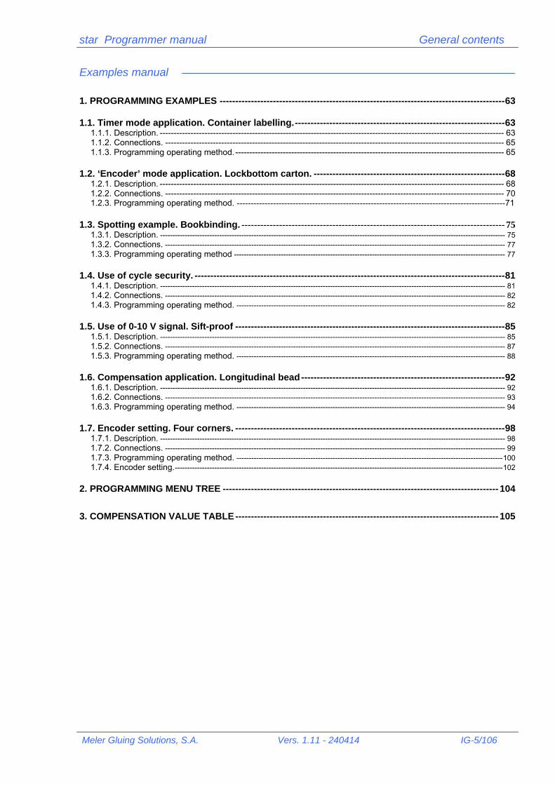
Examples manual
1. PROGRAMMING EXAMPLES ------------------------------------------------------------------------------------------- 63
1.1. Timer mode application. Container labelling. ------------------------------------------------------------------- 63 1.1.1. Description. --------------------------------------------------------------------------------------------------------------------------- 63 1.1.2. Connections. ------------------------------------------------------------------------------------------------------------------------- 65 1.1.3. Programming operating method. ------------------------------------------------------------------------------------------------ 65
1.2. ‘Encoder’ mode application. Lockbottom carton. ------------------------------------------------------------- 68 1.2.1. Description. --------------------------------------------------------------------------------------------------------------------------- 68 1.2.2. Connections. ------------------------------------------------------------------------------------------------------------------------- 70 1.2.3. Programming operating method. ------------------------------------------------------------------------------------------------71
1.3. Spotting example. Bookbinding. ------------------------------------------------------------------------------------ 75 1.3.1. Description. -------------------------------------------------------------------------------------------------------------------------------------------- 75 1.3.2. Connections. ------------------------------------------------------------------------------------------------------------------------------------------ 77 1.3.3. Programming operating method -------------------------------------------------------------------------------------------------------------- 77
1.4. Use of cycle security. --------------------------------------------------------------------------------------------------- 81 1.4.1. Description. -------------------------------------------------------------------------------------------------------------------------------------------- 81 1.4.2. Connections. ------------------------------------------------------------------------------------------------------------------------------------------ 82 1.4.3. Programming operating method. ------------------------------------------------------------------------------------------------------------- 82
1.5. Use of 0-10 V signal. Sift-proof -------------------------------------------------------------------------------------- 85 1.5.1. Description. -------------------------------------------------------------------------------------------------------------------------------------------- 85 1.5.2. Connections. ------------------------------------------------------------------------------------------------------------------------------------------ 87 1.5.3. Programming operating method. ------------------------------------------------------------------------------------------------------------- 88
1.6. Compensation application. Longitudinal bead ----------------------------------------------------------------- 92 1.6.1. Description. -------------------------------------------------------------------------------------------------------------------------------------------- 92 1.6.2. Connections. ------------------------------------------------------------------------------------------------------------------------------------------ 93 1.6.3. Programming operating method. ------------------------------------------------------------------------------------------------------------- 94
1.7. Encoder setting. Four corners. -------------------------------------------------------------------------------------- 98 1.7.1. Description. -------------------------------------------------------------------------------------------------------------------------------------------- 98 1.7.2. Connections. ------------------------------------------------------------------------------------------------------------------------------------------ 99 1.7.3. Programming operating method. ------------------------------------------------------------------------------------------------------------ 100 1.7.4. Encoder setting. ------------------------------------------------------------------------------------------------------------------------------------- 102
2. PROGRAMMING MENU TREE ---------------------------------------------------------------------------------------- 104
3. COMPENSATION VALUE TABLE ------------------------------------------------------------------------------------ 105

star Programmer manual General contents
IG-6/106 Vers. 1.11 - 240414 Meler Gluing Solutions, S.A.

USER MANUAL


star Programmer manual User’s manual
Meler Gluing Solutions, S.A. Vers. 1.11 - 240414 MU-9/106
1. Introduction The star pattern programmer is a control system for dispensing and positioning hot-melt or cold glue in gluing applications, for the markets of Graphic Arts –mailing, folding machines, binding-, Ceramics –high speed boxing-, Foodstuff –labelling- or Agriculture –agricultural set in high speed forming machines—. Ideally adapted to the objective market needs, it is economical, easy to handle and install, with reduced dimensions.
1.1. Definition of equipment The equipment has four (4) independent channels. Each channel can act upon two (2) guns. Maximum power, with the eight (8) guns connected is 150W. It can work in ‘timer’ mode with photocell activation signal and pattern parameters in milliseconds, or in ‘encoder’ mode with the same activation signal and pattern parameters in millimetres, controlled –with reading of the speed of the substrate to be glued- with an encoder. It has a 0-10 V control output to regulate the application pressure with a transducer –proportional valve-, depending on the speed of the substrate. The functions are chosen, the values are programmed and the different menu levels are displayed using a numerical keypad and selection keys. It is possible to activate functions such as ‘spotting’, ‘cycle continues’, manual output activation’, the ‘automatic setting of the encoder impulses’ or the ‘cycle security, which allows total control over the applications, its reliability and repeatability.
1.2. Regulations
The star programmer has been designed under European Standards as shown by the ‘EC’ certification on the characteristics plate Directive 92/31/EEC on Electromagnetic Compatibility Directive 73/23/EEC on Low Voltage
1.3. Warnings on risk prevention The star programmer is supplied by mains current at 230 V / 50 Hz. To avoid the risk of electrical shocks, do not remove the lid or touch anything on the inside, without disconnecting the appliance from the mains. Any manipulation on the inside carried out by unauthorized personnel automatically implies the loss of the right to guarantee. To avoid the risk of fire or electrical shocks, do not expose this product to water or damp. To guarantee the electrical safety of the unit, the installation must be conforming to applicable regulations and the system must be connected to earth.
star Programmer manual User’s manual
MU-10/106 Vers. 1.11 - 240414 Meler Gluing Solutions, S.A.
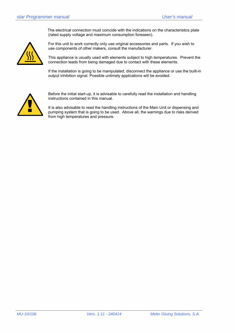
The electrical connection must coincide with the indications on the characteristics plate (rated supply voltage and maximum consumption foreseen). For this unit to work correctly only use original accessories and parts. If you wish to use components of other makers, consult the manufacturer. This appliance is usually used with elements subject to high temperatures. Prevent the connection leads from being damaged due to contact with these elements. If the installation is going to be manipulated, disconnect the appliance or use the built-in output inhibition signal. Possible untimely applications will be avoided.
Before the initial start-up, it is advisable to carefully read the installation and handling instructions contained in this manual. It is also advisable to read the handling instructions of the Main Unit or dispensing and pumping system that is going to be used. Above all, the warnings due to risks derived from high temperatures and pressure.
!

star Programmer manual User’s manual
Meler Gluing Solutions, S.A. Vers. 1.11 - 240414 MU-11/106
2. Technical specifications Power supply: 230 Vac / 50 Hz Output power: 35 W / channel Output voltage: 24 Vcc
33 Vcc (high voltage)-10 Vcc (maintenance)
Output 0-10 V: 24 Vcc (power supply) 0 to 10 Vcc (signal) Photocell/encoder: 15 Vcc (power supply) 15 Vcc output NPN (signal) Channels: 4 Guns per channel: 2 (A-B) Lines per channel: 4 Photocells: 2 Encoder: 1 Channel inhibition: 1 Maximum speed main machine: 400 m/min Minimum application speed: 1 m/min Programming range (encoder): 2-9999 mm Programming range (times): 2-9999 ms Programming tolerance: ±1 Memories: 20 Functions: Response time compensation (activation-deactivation) Erasure of a datum of data from a channel and complete erasure of memory Selection of a photocell for each channel Assignment of spotting parameters for each channel Selection of spotting mode for each line Cycle locking to avoid false photocell readings Accumulated reading of up to four substrates per photocell Independent manual activation for each channel Activation time adjustment (33 Vcc high voltage) for different gun models ’Timer/encoder’ work mode selection Selection of cycle continues, for each program, after machine stoppage Automatic flow regulation, depending on machine speed (0-10 Voutput) for each program Access to programmings by means of security code Screen with production data (machine speed, production per minute, total production) Automatic setting of encoder pulses Electronic protection of output channels (electronic fuse, automatically resettable) Programming in 10 languages (Spanish, French, English, German, Italian, Portuguese, Dutch. Others being developed)

star Programmer manual User’s manual
MU-12/106 Vers. 1.11 - 240414 Meler Gluing Solutions, S.A.
On/off switch
LCD display
Control button panel 10 numerical keys
Control button panel ‘ESCape’ key
Control button panel ‘ENTER’ key
Control button panel ‘Up-left’ cursor key
Control button panel ‘Down-right’ cursor key
3. Programmer description The following chapter includes a description of the controls on the front panel, the connections on the rear of the equipment and the different peripheral elements that can be connected to the equipment
3.1. Front panel The on/off switch starts up the programmer. The entry screen appears after the presentation screens using the password. The programmer is totally active, in the program selected the last time. If the main machine starts to work, the pattern cycle starts as well, according to the relative parameters programmed. The values of the different program parameters are entered with the numerical keypad, or the relative submenu is selected, within a menu.
Type password Password: _
Encoder activation LED
Photocells activation LEDs
Channels activation LEDs

star Programmer manual User’s manual
Meler Gluing Solutions, S.A. Vers. 1.11 - 240414 MU-13/106
Output for guns (two per channel)
Input for encoder Output for regulation 0-10 V
Input for gun inhibition Input for photocells
E.g..: Type password - ‘000’ E.g.: Choose option ‘1. Select program’ - ‘1’ With the ‘ENTER’ key we confirm values entered or we access a later submenu. With the ‘ESC’ key we annul values entered or we access a previous menu. With the cursor keys we can move within the same menu to display the hidden text lines (indicated by means of arrows on screen) or choose an output within a channel
3.2 Connections All the electrical connections are on the rear of the equipment: mains power supply, peripheral connection and inhibition signal.
Type password Password: 000_
1. Select program 2. Utilities
3. Output 0-10 V ← 4. Select photocell →
Select output 1 2 3 4

star Programmer manual User’s manual
MU-14/106 Vers. 1.11 - 240414 Meler Gluing Solutions, S.A.
3.2.1. Output for guns The outputs for gun connection are grouped together two by two in each channel. Thus, for channel 1 there is output 1A and 1B; for channel 2, 2A and 2B, and so on. The connection is carried out with a four (4) threaded pins DIN connector. To connect guns:
1 Positive voltage signal (24 Vcc – 33 V/10 V) 2 Negative voltage signal
3.2.2. Input for photocells Up to two photocells can be connected in their relative connections, so that each one of them controls the cycle start of different guns. The connection is made with a four (4) threaded pins DIN connector. To connect photocells:
1 Positive voltage signal (15 Vcc) 2 Negative voltage signal 3 Switch-over signal (type NPN)
3.2.3. Input for encoder When the ‘encoder’ mode is used there must be a pulse generator element to ‘read’ the substrate movement speed. This generator –encoder- is coupled to its relative connection. To connect the encoder:
1 positive voltage signal (15 Vcc) 2 negative voltage signal 3 switch-over signal (type NPN)
3.2.4. Output for regulation 0-10 V The 0-10 V signal is used to regulate the application pressure, using a transducer –proportional valve-, depending on the substrate speed. For 0-10 V connection:
1 positive voltage signal (0-10 Vcc)
1
2
4
3
1
2
4
3
1
2
4
3
0
V
1
2
4
3

star Programmer manual User’s manual
Meler Gluing Solutions, S.A. Vers. 1.11 - 240414 MU-15/106
2 negative voltage signal 3 supply of transducer element (+24 Vcc) 4 bridge with (2)
2.3.5. Input for gun inhibition With the inhibition input, and using the external connection of a contact without potential, the output signals of the four channels can be annulled, so that the installation is protected from undesired patterns. It acts as a safety device if connected to machine access port contacts or to emergency stop buttons. To connect inhibition input:
1 external signal contact 2 external signal contact 3 bridge with (4) 4 bridge with (3)
2.3.6. Power supply input The power supply connection and the protection fuse are also on the rear of the equipment. The relative connector and lead are supplied to connect the equipment to the mains. Before making the connection, make sure that the mains characteristics coincide with the equipment specifications, indicated in the User’s Manual and on the identification plate it includes. Use the power supply connector fastening flange to secure it. This will avoid problems of false contacts and incorrect operation of the equipment. The power supply input has a 3 A protection fuse. If the equipment fails to come on, check the fuse, unscrewing the lid that protects it a quarter of a turn. Replace it with another one of the same value if it has blown.
For the equipment to work correctly, it is essential to connect the electrical system earth tap.
3.3 Peripheral elements
There are different peripheral elements that can be connected to a star programmer. Maintaining the order in which the connections of the previous chapter have been analysed, we can define:
!
1
2
4
3
2302301401402900004329000043C0121803B1803C0121803B1803
2302301401402900004329000043C0121803B1803C0121803B1803

star Programmer manual User’s manual
MU-16/106 Vers. 1.11 - 240414 Meler Gluing Solutions, S.A.
3.3.1. Guns All the MAC solenoid valve controlled ‘meler’ guns, 24 Vcc version (limited by the output power) can be connected: bead, coating, swirl or spray guns, in their simple acting (MS) or double acting version (MD), microprecision and adjustable microprecision guns and ‘compact’ series guns, also in both the single (MS) or double-acting (MD) versions. ‘Pafra’ guns for cold glue controlled by MAC solenoid valves, 24 Vcc version (limited by the output power): guns series 87 and series 88. ‘Pafra’ guns for cold glue controlled by electromagnet (limited by output power): guns series 86 and series 33.
To connect any other type of guns consult with factory.
3.3.2. Photocells Two types of photocells are supplied depending on the work to be carried out. In the majority of the applications it is sufficient to use the reflection photocell –directly onto the object- ref. 27000001, with threaded body M18x1 to make anchorage easy. This has a sensitivity adjustment screw. Its detection distance is 30 cm and it can be used in operation mode with light or in darkness (cabled). The control output is NPN type. For applications in small spaces, with difficult access or small-sized substrates, the photocell for reflection optic fibre can be used—directly onto object— ref. 27000002, with threaded end M6 and self-adjusting ‘teaching’ function. Its detection distance is 110 mm and it can be used in operation mode with light or in darkness (selector). The control output is NPN type.
To connect any other type of photocell consult with factory.
3.3.3. Encoder Three (3) types of encoders are available to users —200 (ref. 25010007), 400 (ref. 25010008) y 1000 (ref. 25010009) pulses per revolution— with two (2) different fastening versions —for belt, with running disc; for shaft, with elastic coupling— . The 200-pulse model is designed to be placed directly onto the displacement belt of the substrate to be glued, so that the programmer works with a ratio of 1 pulse = 1 mm. In other cases the self-adjustment function of the encoder must be used to find the correct ratio. All the models work at 15 Vcc with NPN or push-pull output. The belt support has a tension system, with a torsion spring, to ensure permanent contact of the wheel on the belt. The elastic coupling, in the support for shaft, has an opening for Ø10 mm shaft.
To connect any other type of encoder consult with factory.
!
!
!

star Programmer manual User’s manual
Meler Gluing Solutions, S.A. Vers. 1.11 - 240414 MU-17/106
3.3.4. Pressure regulator When the 0-10V output is used the pneumatic supply pressure of the application pump must be controlled in order, depending on the machine speed, to apply the necessary hot-melt flow volume. There is a pneumatic pressure regulation system –or proportional valve— VP-200 (ref. 08000005), which transforms the output voltage of the programmer (0-10 Vcc) into pneumatic pressure corresponding to the pump (0-6 bar). The correspondence is linear and can be programmed from the equipment (see Programming Manual) or from the actual VP-200. This peripheral requires 24 Vcc electrical supply, provided by the star programmer and pneumatic supply (max. 10 bar), through a built-in 5µ filter. The VP-200 has a display that shows the existing pressure at any time.
To connect any other type of pressure regulator consult with factory.
!
star Programmer manual User’s manual
MU-18/106 Vers. 1.11 - 240414 Meler Gluing Solutions, S.A.
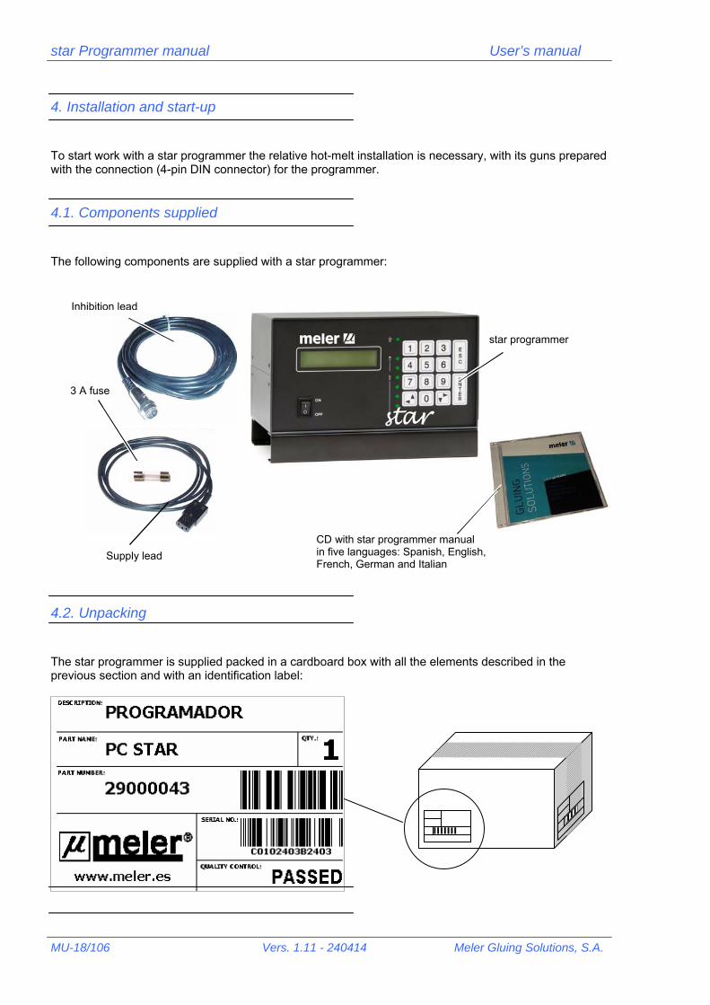
4. Installation and start-up To start work with a star programmer the relative hot-melt installation is necessary, with its guns prepared with the connection (4-pin DIN connector) for the programmer.
4.1. Components supplied The following components are supplied with a star programmer:
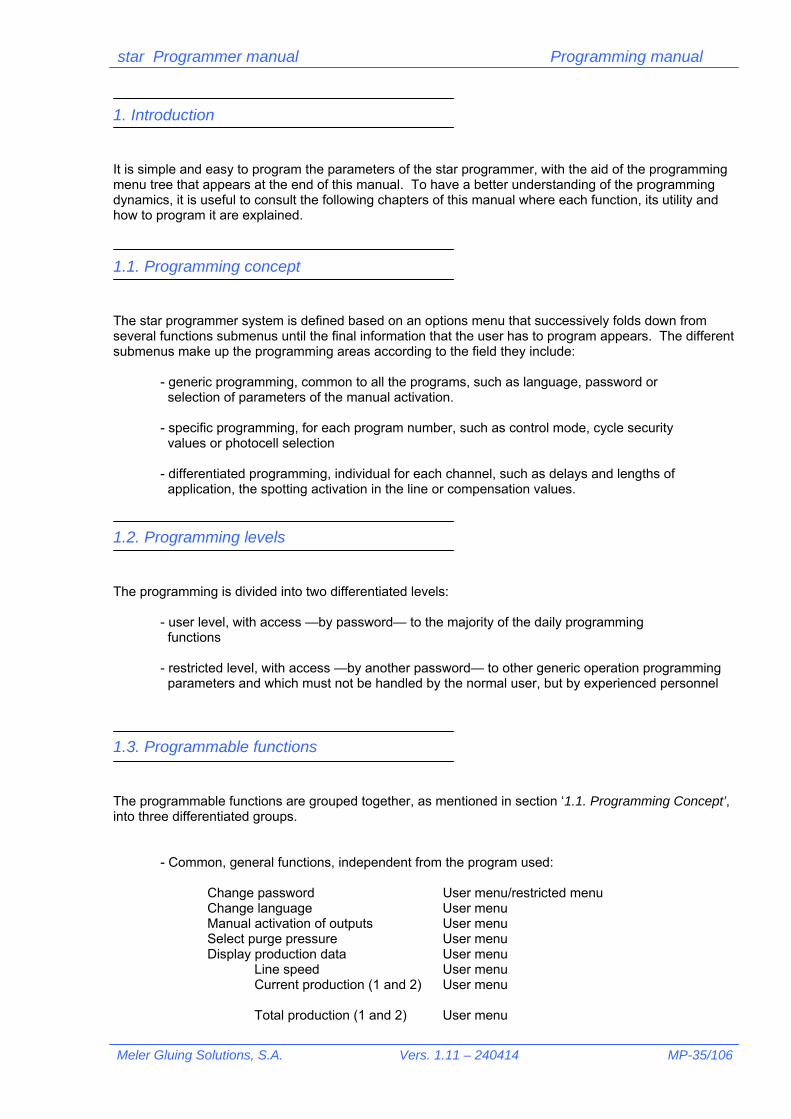
4.2. Unpacking The star programmer is supplied packed in a cardboard box with all the elements described in the previous section and with an identification label:
Inhibition lead
Supply lead
star programmer
3 A fuse
CD with star programmer manual in five languages: Spanish, English, French, German and Italian

star Programmer manual User’s manual
Meler Gluing Solutions, S.A. Vers. 1.11 - 240414 MU-19/106
The identification (‘Part number’ & ‘Serial nº’) corresponds to the same data contained on the programmer plate.
Reject any packaging that does not have the relative labels or whose information does not match with that requested.
When you unpack the programmer, keep the cardboard box and the packaging material in case you wish to move or send the equipment in the future. If any of the components supplied (see point 4.1) are missing or damaged, inform the ‘meler’ dealer immediately or the central offices in Pamplona. All the components are packed in their relative bags with their identification labels.
Place the programmer on a flat stable surface. The legs of the programmer have grooves to secure the legs to the surface, using screws. Situate the programmer close to the installation (guns, photocells, encoder, etc.) in order to easily connect the leads. The standard length of these leads is 3 m. The power supply lead supplied measures 5 m long. Locate the programmer at a height where the display can easily be seen and the programming keypad can be reached. Leave sufficient space on the rear so that the connection lead output is not forced and the connection can easily be made. Avoid places subject to knocks or vibrations.
!
220190
3012
0
158190
150
220190
3012
0
158190
150

star Programmer manual User’s manual
MU-20/106 Vers. 1.11 - 240414 Meler Gluing Solutions, S.A.
4.3. Electrical installation Avoid connecting the programmer in lines that share the circuit with motors or large devices that might cause fluctuations in the line voltage. Make sure that both the programmer and the installation are far away from potential electromagnetic interference sources (frequency variators, wireless telephony or public address speakers). Use the yellow-green earth lead to connect to the factory installation earth. Connect the programmer to an alternating current source of 230 V, 50 Hz.
Plug the supply lead connector into the rear of the equipment.
Secure connection with the flange supplied with the lead. Connect the other end of the lead to the relative intake –according to regulations of each country- or to the connection terminals of the main machine.
Connect to a 230 V, 50 Hz alternating current source with earth tap
Connect the peripheral elements –guns, photocells, encoder, 0-10 V signal lead and / or gun inhibition signal lead –with the 4-pole DIN connectors.
Firmly screw in the check nut. Make sure that each peripheral is connected into its relative place.
!

star Programmer manual User’s manual
Meler Gluing Solutions, S.A. Vers. 1.11 - 240414 MU-21/106
4.4. Location of the peripheral elements For the system to work perfectly it is advisable to place the photocell so that it detects the substrate correctly, without false readings and enabling the hot-melt to be applied from the start of the actual substrate. The positioning and length of the application lines and their precision, independent from the changes in speed of the machine, mean that certain considerations must be taken into account when situating the encoder, avoiding erroneous readings or displacement of the wheel on the substrate displacement belt.
4.4.1. Photocell The photocells must be placed so that it detects the substrate to be glued, but, when this is not present, there must not be any reflecting surface that might activate it. The actual detection distance of each photocell must be taken into account and its activation margin respected. There must be a clear contrast between the substrate to be detected and the absence of this substrate. For example, a white surface could
be detected if, when this is not present, the existing surface were to be black.
ENCODER
GUN
0 -10 V
INHIBITION
PHOTOCELL
ENCODER
GUN
0 -10 V
INHIBITION
PHOTOCELL

star Programmer manual User’s manual
MU-22/106 Vers. 1.11 - 240414 Meler Gluing Solutions, S.A.
To adjust the sensitivity of the photocell (ref. 27000001), the adjustment screw can be used. In clockwise direction the sensitivity increases. In the opposite direction, it decreases. In the case of the photocell for optical fibre (ref. 27000002) apply the ‘teach’ key and follow the procedure.
If the photocell must be placed in the opposite position –with the lens upwards- prevent any light from the main machine installation falling upon it. Although the photocells detect infrared light, some fluorescent lights might activate them accidentally.
In hot-melt application systems do not place the photocell very close to the guns. The heat that these give off may affect and even destroy them. The distance between the photocell and the gun-in the substrate displacement line- is a determining factor when applying certain formats at certain machine speeds. The recommendations to avoid problems with this position are described in the ‘Programming manual’. The installation can be started with a distance of 50 mm, sufficient in the majority of the applications.
4.4.2. Encoder
The encoder (ref. 25010007) must be placed in a position where it can ‘read’ the substrate displacement speed. Avoid placing it on ‘transfers’ or ‘pressure accumulator’, belts, controlled by other motors than that of the main belt.
Do not place the encoder on tension wheels of the contact area. At those points, the belt undergoes tensions that modify its speed with respect to the rest of the belt.
NOKNOK
OKOK
NOKNOKNOKNOK
OKOKOKOK

star Programmer manual User’s manual
Meler Gluing Solutions, S.A. Vers. 1.11 - 240414 MU-23/106
Use the tension system, by means of the torsion spring, incorporated in the belt support of the encoder (ref. 25010010). To tighten it, gently place in the end position and turn the arm, tightening it forwards –anti-clockwise, looking from the wheel side-. Keep in this position and tighten the screw.
Do not overtighten. There must always be a little play to assume small variations in the surface.
Place the encoder on smooth surface, without joints or protuberances that might make the contact wheel with the belt come out and thus ‘lose’ reading pulses. If any other type of encoder is used (ref. 25010008 ó 25010009) where the pulse/displacement ratio is not 1:1, follow the setting instructions indicated in the ‘Programming manual.
4.5. Programmer Set-up After installing the programmer and verifying the correct location of all the peripherals, start it up with the power on/off switch on the front panel. After the presentation screens, the name of the programmer appears, the version and the contact telephone for technical assistance, the first interactive screen of the programmer is displayed, where the password is requested.
The default password (factory programmed) is ‘000’. This password can be changed in the ‘Utilities’ menu (see ‘Programming manual). Press [0] [0] [0] and [ENTER]. The next screen will appear. Press [2] and [ENTER]. Enter the ‘Utilities’ menu. Press []. The next screen of the menu will appear. Press [2] and [ENTER].
Type password Password: _
Type password Password: 000_
1. Select program 2. Utilities
Utilities 1. Change password →
1. Change password ← 2. Change language →

star Programmer manual User’s manual
MU-24/106 Vers. 1.11 - 240414 Meler Gluing Solutions, S.A.
To select a language press the relative number [no] and [ENTER]. The texts are automatically displayed in the chosen language.
To access the other languages, on successive screens, press [] as many times as necessary. To access languages from previous screens, press [].
Currently 7 languages have been stored:
1. Spanish / 2. English / 3. French / 4. Italian / 5. German / 6. Dutch / 7. Portuguese
Return to the initial selection screen pressing [ESC] several times, until you reach it. Press [1] and [ENTER]. The following screen will appear. Type the program number chosen –they are all identical-, e.g. [1] and [ENTER]. Press [] twice. The following screen appears. Press [4] and [ENTER] to access the photocell selection –1 or 2- and assign them to each channel—1, 2, 3 or 4—. In this case photocell 1 (T: Trigger) is assigned to outputs (O: Output) 1 y 2, and photocell 2 to outputs 3 and 4. To change a value, go to the relative output with keys [] and
[],enter the desired value [1] or [2] and press [ENTER] to memorise the change. Return to the general menu screen of the program by pressing [ESC] several times until you reach it. Press [] three times. The following screen will appear. Press [5] and [ENTER] to access the work mode in ‘Timer’ or ‘Encoder’. The option between brackets is the selection currently in use. To change the option, press [ENTER]. Each time it is pressed, the selection changes option.
Working in ‘Timer’ mode presupposes the use of a cycle activation photocell and parameters expressed in milliseconds (ms). Working in ‘Encoder’ mode assumes using a cycle activation photocell, a pulse generator to read the speed of the machine and parameters expressed in millimetres (mm).
1. Spanish 2. English →
!
1. Select program 2. Utilities
Type program number (1 – 20): _
Program N. # 1 1. Pattern →
3. Output 0-10 V ← 4. Select photocell →
O1 T:1 O2 T:1 O3 T:2 O4 T:2 →
Program N. # 1 1. Pattern →
4. Select photocell ← 5. Control mode →
Control mode Timer [Encoder] →
!

star Programmer manual User’s manual
Meler Gluing Solutions, S.A. Vers. 1.11 - 240414 MU-25/106
After taking these actions the programmer is set to be able to work in the application defined. After this the application values —delays and lines— must be programmed, as well as spotting mode channel selection and values —if this function is used—, 0-10 V output values to regulate the pneumatic pressure —if this function is used—, high voltage time values and compensations —depending on the type of gun used—, setting the encoder pulse/displacement ratio —if this is not 1:1—, etc. To program all these parameters and functions you can consult the ‘Programming manual’.

star Programmer manual User’s manual
MU-26/106 Vers. 1.11 - 240414 Meler Gluing Solutions, S.A.
5. Maintenance For the programmer and its peripherals to work correctly, some simple indications for the care and maintenance of the system must be followed. The periodicity of this care depends on the time of use, on the environmental conditions and on possible external aggressions —friction, splashes of adhesive, contact with high temperature areas, etc—. As a general rule, it is advisable to carry out a visual inspection once a month.
5.1. Outside cleaning To keep the outside of the programmer clean, clean the equipment with a soft cloth —slightly moistened with water—. Do not use solvents —turpentine, benzene, etc—, which may deteriorate the equipment surface.
Before carrying out any intervention to the equipment, switch it off and unplug the power supply lead.
5.2. Care of connection leads
Keep the equipment power supply lead in perfect conditions. Replace it (ref. 16020001) if any deterioration is observed. Also keep the leads of peripherals –guns, photocells, encoder, etc- in excellent conditions. Replace them if any damage to them is observed (consult spare parts references).
Respect the type and section of the leads replaced. Not doing so may lead to serious damage to the equipment or to the people handling it.
!
!

star Programmer manual User’s manual
Meler Gluing Solutions, S.A. Vers. 1.11 - 240414 MU-27/106
5.3. Care of peripheral elements Clean the optic lens of the photocell with a soft cloth, without scratching it. Readjust its sensitivity if necessary.
Keep the support joints of the encoder on the belt clean and in good conditions. If they are deteriorated or extremely soiled, replace them (ref. 25010016).
Verify the support pressure of the encoder on the belt to eliminate displacements and loss of control pulses. Adjust the support spring if necessary. If there is a considerable loss of force of the spring pressure, replace it (ref. 25010020).

star Programmer manual User’s manual
MU-28/106 Vers. 1.11 - 240414 Meler Gluing Solutions, S.A.
5.4. Troubleshooting This section exclusively contemplates the problems caused by connections or positioning errors, beyond the programming itself. The star programmer does not come on when the switch is connected. Verify correct connection to mains. Verify power supply lead. Verify fuse situated on the rear of the equipment. The system does not activate the application elements
Verify that the guns are connected to the programmed channels and secured with the threaded fastening of the connector. Verify that the channel inhibitor is not activated. Verify the correct assignment of the photocells to each output. One (or more) channels are not activated or they are activated with a brief impulse. Verify the lead of the outputs from that channel. Possible internal activation of protection against short-circuits. Change connection to another channel and verify operation. Working at very low speed, in encoder mode, the application elements are not activated. Below 1 m/min, the programmer annuls the applications. Increase speed above this value The photocell always remains activated. Incorrect sensitivity adjustment. Adjust it. An object, situated under it, reflects the emission of the photocell in the absence of substrate. Adjust sensitivity or change the photocell position.

star Programmer manual User’s manual
Meler Gluing Solutions, S.A. Vers. 1.11 - 240414 MU-29/106
The photocell does not detect the substrate at the same time, so the application has position variations. The substrate area detected by the photocell has variations in height from one part to another. Guide this area when passing through the detection. Some substrates pass out of line or with a lack of material. The encoder does not measure the correct machine speed. The encoder wheel moves due to lack of pressure on the belt. Verify the grip of the grub screw of the wheel. The encoder has been placed at a different speed point to the displacement of the substrate. An encoder with different impulse/displacement ratio to the one selected has been placed.

star Programmer manual User’s manual
MU-30/106 Vers. 1.11 - 240414 Meler Gluing Solutions, S.A.
6. Accessories and parts
Ref. 27000001
COMPLETE PHOTOCELLWITH LEAD AND CONNECTOR
Ref. 27000002
OPTICAL FIBREPHOTOCELL
Ref. 10010009 3 A FUSE
Ref. 25010017 ENCODER WHEEL
Ref. 25010016 ENCODER WHEEL
GASKETS
Ref. 25010010 / 25010011 COMPLETE ENCODER SUPPORT FOR BELT
COMPLETE ENCODER SUPPORT FOR SHAFT
Ref. 25010018 ENCODER
CONNECTION
Ref. 16000005
CON
Ref. 16000006
COMCOMPLETE CURRENTINTAKE CONNECTOR
Ref. 16020001
COMPLETE CURRENTINTAKE CONNECTOR
3 m LEAD GUN INHIBITION
AERIAL MALE CONECTOR WITH 3 m LEAD
3 m EXTENSIÓN WITH METAL CONNECTOR
PHOTOCELL-ENCODER
Ref. 16130001
Ref. 25010007 / 25010008 / 2501009 COMPLETE INCREMENTAL ENCODER
200 / 400 / 1000 PULSES

star Programmer manual User’s manual
Meler Gluing Solutions, S.A. Vers. 1.11 - 240414 MU-31/106
Ref. 08000004 / 08000005 PRESSURE VARIATOR ACCESSORY KIT VP-200
PRESSURE VARIATOR ACCESSORY KIT VP-200 WITH AERIAL CONNECTOR
Ref. 21120003 Complete solenoid valve 3/2 24 Vcc 12.7 W Ref. 21020003 Complete solenoid valve 4/2 24 Vcc 12.7 W Ref. 21150002 Complete solenoid valve 5/2 24 Vcc 12.7 W Ref. 112000090 Complete solenoid valve 3/2 24 Vcc 12.7 W quick connection Ref. 112000010 Complete solenoid valve 4/2 24 Vcc 12.7 W quick connection Ref. 112000110 Complete solenoid valve 5/2 24 Vcc 12.7 W quick connection Ref. 112000020 Complete solenoid valve 5/2 24 Vcc 12.7 W quick connection (for adjustable microprecision gun)
Ref. 21150002 Complete solenoid valve 5/2 24 Vcc 12.7 W

star Programmer manual User’s manual
MU-32/106 Vers. 1.11 - 240414 Meler Gluing Solutions, S.A.

PROGRAMMING MANUAL

star Programmer manual Programming manual
Meler Gluing Solutions, S.A. Vers. 1.11 – 240414 MP-35/106
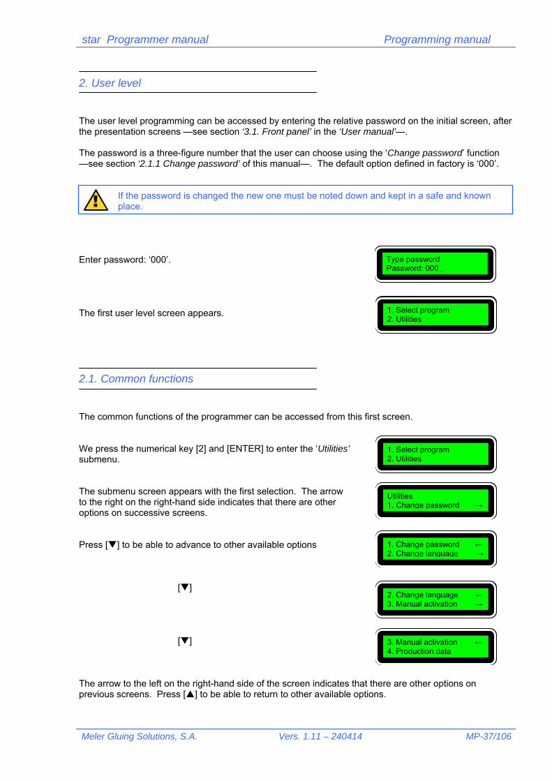
1. Introduction It is simple and easy to program the parameters of the star programmer, with the aid of the programming menu tree that appears at the end of this manual. To have a better understanding of the programming dynamics, it is useful to consult the following chapters of this manual where each function, its utility and how to program it are explained.
1.1. Programming concept The star programmer system is defined based on an options menu that successively folds down from several functions submenus until the final information that the user has to program appears. The different submenus make up the programming areas according to the field they include:
- generic programming, common to all the programs, such as language, password or selection of parameters of the manual activation. - specific programming, for each program number, such as control mode, cycle security values or photocell selection - differentiated programming, individual for each channel, such as delays and lengths of application, the spotting activation in the line or compensation values.
1.2. Programming levels The programming is divided into two differentiated levels:
- user level, with access —by password— to the majority of the daily programming functions
- restricted level, with access —by another password— to other generic operation programming parameters and which must not be handled by the normal user, but by experienced personnel
1.3. Programmable functions The programmable functions are grouped together, as mentioned in section ‘1.1. Programming Concept’, into three differentiated groups.
- Common, general functions, independent from the program used: Change password User menu/restricted menu Change language User menu Manual activation of outputs User menu Select purge pressure User menu Display production data User menu Line speed User menu Current production (1 and 2) User menu Total production (1 and 2) User menu

star Programmer manual Programming Manual
MP-36/106 Vers. 1.11 - 240414 Meler Gluing Solutions, S.A.
Display user password Restricted menu Change service phone Restricted menu High voltage time setting Restricted menu Encoder setting Restricted menu Pulses per mm Restricted menu Product size Restricted menu Line speed Restricted menu Program selection User menu - Program functions —from the user menu—, assigned independently to each program: Select output channel
Select spotting mode per output channel Output values 0-10 V Assign photocell to each output channel
Cycle security value for each photocell Select control mode, ‘Time’ or ‘Encoder’ Select cycle continues Erase memory
- Output channel functions —from user menu—, assigned independently to each output channel: Delay of up to four application lines Length of up to four application lines Spotting values per output channel Activate spotting mode per line Partially erase data
Compensation values
star Programmer manual Programming manual
Meler Gluing Solutions, S.A. Vers. 1.11 – 240414 MP-37/106
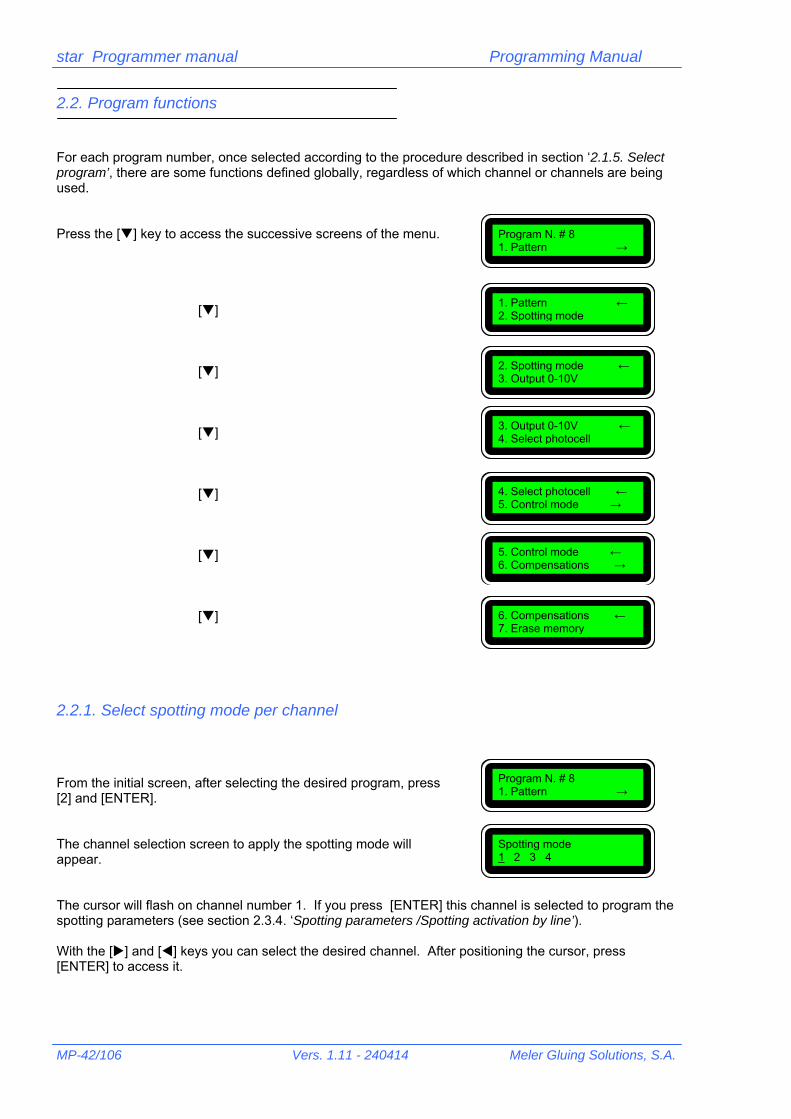
2. User level The user level programming can be accessed by entering the relative password on the initial screen, after the presentation screens —see section ‘3.1. Front panel’ in the ‘User manual’—. The password is a three-figure number that the user can choose using the ‘Change password’ function —see section ‘2.1.1 Change password’ of this manual—. The default option defined in factory is ‘000’.
If the password is changed the new one must be noted down and kept in a safe and known place.
Enter password: ‘000’. The first user level screen appears.
2.1. Common functions
The common functions of the programmer can be accessed from this first screen. We press the numerical key [2] and [ENTER] to enter the ‘Utilities’ submenu. The submenu screen appears with the first selection. The arrow to the right on the right-hand side indicates that there are other options on successive screens. Press [] to be able to advance to other available options
[]
[]
The arrow to the left on the right-hand side of the screen indicates that there are other options on previous screens. Press [] to be able to return to other available options.
!
Type password Password: 000_
1. Select program 2. Utilities
1. Select program 2. Utilities
Utilities 1. Change password →
1. Change password ← 2. Change language →
2. Change language ← 3. Manual activation →
3. Manual activation ← 4. Production data

star Programmer manual Programming Manual
MP-38/106 Vers. 1.11 - 240414 Meler Gluing Solutions, S.A.
2.1.1. Change password On the screen of the ‘Utilities’ submenu, press [1] and [ENTER]. A new screen appears. Enter the three new digits and press [ENTER]. The cursor will go to the second bracket for you to confirm the password chosen. Enter the three digits again and press [ENTER]. The password is automatically registered. The program returns to the previous screen. If you make a mistake when typing the digits the invalidation screen appears. Press [ESC] to return to the previous screen.
Take note of the new password and keep it in a place where you can consult it if you forget it. The programmer does not permit access if the correct password is not entered.
2.1.2. Select language
The star programmer permits selecting the screen language from a list of 10 possibilities (currently only seven of them have been activated). On the ‘Utilities’ submenu screen, press [2] and [ENTER]. The screen appears with the list of languages. Press key [] to be able to advance to other available options.
[]
Utilities 1. Change password →
Type new password ( _ ) ( )
Type new password ( 888 ) ( _ )
Utilities 1. Change password →
INVALID PASSWORD Press <ESC>
Utilities 1. Change password →
!
1. Change password ← 2. Change language →
1. Spanish 2. English →
2. English ← 3. French →
3. French ← 4. Italian →

star Programmer manual Programming manual
Meler Gluing Solutions, S.A. Vers. 1.11 – 240414 MP-39/106
[] [] []
The star programmer is factory selected in the ‘Spanish’ language. To select a new language press the relative number and [ENTER]. For example, to select the ‘Dutch’ language: Press [6] and [ENTER] The programmer will immediately present the screen with the translation in the language chosen.
2.1.3. Manual activation/Purge pressure
Manual activation permits directly activating and deactivating each one of the four output channels by pressing the [ENTER] key. It is possible select one or more guns to carry out this function. It is also possible, on a second screen, to select the 0-10 V signal corresponding to the pressure with which the output channels are going to be activated (in a system with proportional regulation of the application pressure). On the ‘Utilities’ submenu screen, press [3] and [ENTER]. The channel selection screen will appear as well as their activation / deactivation. The cursor will flash on channel number 1. If you press the [ENTER] key, this channel is selected to be activated / deactivated. An asterisk will appear next to the channel number, indicating that this has been selected. For example: select channel 3. With the [] arrow, go to number 3 and press the [ENTER] key. Channel 3 is selected. As many channels as you wish can be selected with this
4. Italian ← 5. German →
5. German ← 6. Dutch →
6. Dutch ← 7. Portuguese
5. German ← 6. Dutch →
5. Deutsch ← 6. Nederlands →
2. Change language ← 3. Manual activation →
Manual activation 1 2 3 4 [OFF] →
Manual activation 1 2 3 4 [OFF] →
Manual activation 1 2 3* 4 [OFF] →

star Programmer manual Programming Manual
MP-40/106 Vers. 1.11 - 240414 Meler Gluing Solutions, S.A.
procedure. To eliminate the selection do the same with the numbers that already have an asterisk. After selecting the channels, to activate / deactivate them the cursor must be placed, with the [] arrow on the position marked with the word [OFF]. This word indicates that the system is deactivated. If the [ENTER] key is pressed, the word [ON] will appear indicating that the system is activated and therefore the outputs of the selected channels have been activated. Place the cursor on [OFF]. Press [ENTER]. The selected output channel or channels will remain activated and their relative led or leds of the front panel will be on. Press the [ENTER] key again.
The selected output channel or channels will remain deactivated and their relative led or leds of the front panel will be off.
In this last position —[OFF] ; [ON]— the [] key can be pressed, permitting access to a new screen. On this screen select the 0-10 V signal corresponding to the pressure at which you wish to activate the selected output channels. Enter the value, in tenths of a volt and confirm with the [ENTER] key. Values from 0 to 100 are permitted.
Manual activation 1 2 3* 4 [OFF] →
Manual activation 1 2 3* 4 [ON] →
Manual activation 1 2 3* 4 [OFF] →
Purge pressure ← 50Vcc/10
LED

star Programmer manual Programming manual
Meler Gluing Solutions, S.A. Vers. 1.11 – 240414 MP-41/106
2.1.4. Production data The star programmer permits reading certain information details about line speed and parts production (substrates). On the ‘Utilities’ submenu screen, press [4] and [ENTER]. The ‘Line speed’ information screen will appear, indicating the current speed of the pieces (substrate). Press the [] key to access the ‘Production quant.’ screen, which indicates the pieces per hour detected by the photocell connected to input number 1. Press the [] key to access the ‘Production quant.’, which indicates the pieces per hour detected by the photocell connected to input number 2. Press the [] key to access the ‘Total production’ screen, which indicates the total pieces detected by the photocell connected to input number 1, from the last time the counter was erased. Letter [R] permits resetting the counter, pressing [ENTER]. Press the [] key to access the ‘Total production’ screen, which indicates the total pieces detected by the photocell connected to input number 2, from the last time the counter was erased. Letter [R] permits resetting the counter, pressing [ENTER]. By pressing [ESC] on any of the screens you can access the initial screen.
2.1.5. Select program From the main menu you can select any of the twenty (20) possible programs that the star programmer incorporates. To do so, press key [1] and [ENTER], and the introduction screen of the desired program will appear. By default the last program selected will appear flashing on and off, e.g.: 5. To select another program, e.g.: 8 press [8] and [ENTER]. The screen will show the menu of the selected program. Once you have chosen the program, this becomes the active program —the one which is executed— and also the edited program —permits carrying out settings and changes to the parameters of this program—.
3. Manual activation ← 4. Production data
Line speed 115 m/min →
Production quant. ← 24600 Pieces/h 1 →
Production quant. ← 24600 Pieces/h 2 →
Total production ← 158000 Pieces1 [R] →
Total production ← 158000 Pieces2 [R]
Utilities 1. Change password →
1. Select program 2. Utilities
Type program number ( 1 – 20 ) : 5
Program N. # 8 1. Pattern →
star Programmer manual Programming Manual
MP-42/106 Vers. 1.11 - 240414 Meler Gluing Solutions, S.A.
2.2. Program functions For each program number, once selected according to the procedure described in section ‘2.1.5. Select program’, there are some functions defined globally, regardless of which channel or channels are being used. Press the [] key to access the successive screens of the menu.
[] [] [] [] [] []
2.2.1. Select spotting mode per channel From the initial screen, after selecting the desired program, press [2] and [ENTER]. The channel selection screen to apply the spotting mode will appear. The cursor will flash on channel number 1. If you press [ENTER] this channel is selected to program the spotting parameters (see section 2.3.4. ‘Spotting parameters /Spotting activation by line’). With the [] and [] keys you can select the desired channel. After positioning the cursor, press [ENTER] to access it.
Program N. # 8 1. Pattern →
Program N. # 8 1. Pattern →
1. Pattern ← 2. Spotting mode
2. Spotting mode ← 3. Output 0-10V
3. Output 0-10V ← 4. Select photocell
4. Select photocell ← 5. Control mode →
5. Control mode ← 6. Compensations →
6. Compensations ← 7. Erase memory
Spotting mode 1 2 3 4

star Programmer manual Programming manual
Meler Gluing Solutions, S.A. Vers. 1.11 – 240414 MP-43/106
2.2.2. Control values 0-10V This function is used when the installation includes a proportional application pressure regulator depending on the substrate displacement speed. From the initial screen, after selecting the desired program, press [3] and [ENTER]. The screen to select the 0-10V output values assigned to the maximum and minimum work speed will appear. These two values generate a proportional voltage-speed interpolation.
To program these values, substrates are made to pass at a low speed, e.g. 20 m/min. With the machine in movement, at this speed, enter a value in the ‘Min’ position on the screen, e.g. 10 Vcc and press [ENTER]. The value that we have entered and the speed of the substrate at the time it was entered will appear. Observe the thickness of the line applied. If it is not sufficient, enter a greater voltage value than the current one. If the opposite is the case, reduce it. If the thickness is appropriate, increase the speed of the machine, e.g. 100 m/min. With the machine in movement, at this speed, enter a value in the ‘Max’ position on the screen, e.g. 60 Vcc and press [ENTER]. The value that we have entered and the speed of the substrate at the time it was entered will appear. Observe the thickness of the line applied. If it is not sufficient, enter a higher voltage value than the current one. If the opposite is the case, reduce it. If the thickness is appropriate, the value programming has finished. In this situation, variations in speed of the machine will produce an evenly applied line thickness.
Program N. # 8 1. Pattern →
Min: _ 0 Vcc 0 m/min Max: 100Vcc 400 m/min
Min: 10 Vcc 20 m/min Max: 100Vcc 400 m/min
Min: 10 Vcc 20 m/min Max: 60Vcc 100 m/min

star Programmer manual Programming Manual
MP-44/106 Vers. 1.11 - 240414 Meler Gluing Solutions, S.A.
2.2.3. Select photocell/Cycle security A different photocell (of the two possible ones) can be assigned to each output channel, for the cycle start signal. Associated with the working of the photocell, it is also possible ‘to lock’ its reading for a specified distance. This latter function will prevent undesired readings from being made, whilst a substrate is passing under the photocell, caused by changes in colour, gloss, or grooves, holes and flaps of the box that we do not want to detect. From the initial screen, after selecting the desired program, press [4] and [ENTER]. The photocell assignment screen (T:Trigger) will appear for each output channel (O: Output). The selection is made between 1 or 2. You can select the desired channel with keys [] and []. After positioning the cursor, press [1] or [2] as desired and [ENTER] to confirm. If you press [] when positioned on channel—‘O4’— you will access the following screen, where the security of cycle for each photocell is programmed. You can select the desired photocell with keys [] and []. After positioning the cursor, press the numerical keys of the relative value —generally, the length of a substrate plus five (5) millimetres— and [ENTER] to confirm.
The programmer has accumulated reading of up to four substrates per photocell, that is, it can ‘read’ four substrates before starting to apply on the first, which means that the photocell and the gun can be placed with a considerable distance between them or, after defining a distance
between photocell and gun, the two substrates can be moved as close as possible together.
2.2.4. Select control mode / Cycle continues You can work in two different modes with the star programmer: in ‘timer’ mode, with programming in milliseconds —it acts as a timer— and in ‘encoder’ mode, with programming in millimetres —it acts as an impulse counter—. In this second case, a second screen enables you to select if, in the case of a machine stoppage, the cycle should be annulled and a new one should start with a new photocell detection (‘Cycle continues: NO’) or on the contrary, it is stored in memory so that it can end when the machine starts up again (‘Cycle continues: YES’). From the initial screen, after selecting the desired program, press [5] and [ENTER]. The mode selection screen will appear. The mode between brackets is the mode currently selected. Just press [ENTER] to change from one working mode to another.
01 T:1 02 T:1 03 T:2 04 T:2 →
Program No. # 8 1. Pattern →
Security of cycle ← T1: _200 T2 : 200
Program N. # 8 1. Pattern →
Control mode Time [Encoder] →
Control mode [Time] Encoder →
!
star Programmer manual Programming manual
Meler Gluing Solutions, S.A. Vers. 1.11 – 240414 MP-45/106
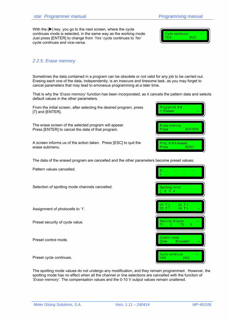
With the [] key, you go to the next screen, where the cycle continues mode is selected, in the same way as the working mode. Just press [ENTER] to change from ‘Yes’ cycle continues to ‘No’ cycle continues and vice-versa.
2.2.5. Erase memory Sometimes the data contained in a program can be obsolete or not valid for any job to be carried out. Erasing each one of the data, independently, is an insecure and tiresome task, as you may forget to cancel parameters that may lead to erroneous programming at a later time. That is why the ‘Erase memory’ function has been incorporated, as it cancels the pattern data and selects default values in the other parameters. From the initial screen, after selecting the desired program, press [7] and [ENTER]. The erase screen of the selected program will appear. Press [ENTER] to cancel the data of that program. A screen informs us of the action taken. Press [ESC] to quit the erase submenu. The data of the erased program are cancelled and the other parameters become preset values: Pattern values cancelled. Selection of spotting mode channels cancelled. Assignment of photocells to ‘1’. Preset security of cycle value. Preset control mode. Preset cycle continues. The spotting mode values do not undergo any modification, and they remain programmed. However, the spotting mode has no effect when all the channel or line selections are cancelled with the function of ‘Erase memory’. The compensation values and the 0-10 V output values remain unaltered.
Cycle continues ← YES [NO]
Program N. # 8 1. Pattern →
Erase memory Press [ENTER]
Prog. N.# 8 erased Press [ESC]
D .... .... .... .... L .... .... .... ....
Spotting mode 1 2 3 4
01 T:1 02 T:1 03 T:1 04 T:1 →
Security of cycle ← T1: _ 2 T2 : 2
Control mode Time [Encoder] →
Cycle continues ← YES [NO]

star Programmer manual Programming Manual
MP-46/106 Vers. 1.11 - 240414 Meler Gluing Solutions, S.A.
2.2.6. Select output channel From the initial screen, after selecting the desired program, press [1] and [ENTER]. The channel selection screen will appear. With keys [] and [] select the channel and press [ENTER]. The data —if any— of the delay values (D: Delay) and the pattern length (L: Length) for each one of the four lines of the channel selected are displayed on the screen.
2.3. Output channel functions Just like the functions that are common to the whole program have been described (in section ‘2.2. Program functions’), in this section the functions that are specific for each channel are going to be described and which, therefore, can be programmed differently for each one of them.
2.3.1. Delay of each line The pattern values screen has already been shown in section ‘2.2.6. Select output channel’. Here four sets of dots appear, placed in two rows, where the values corresponding to four possible patterns of a program can be entered.
This screen is accessed from the ‘program selection’ in the first place, with the ‘pattern’ secondly and later with the ‘select output channel’.
The delay of a line –or strip of adhesive applied- is given by the position where you wish to start the application of the relative line. As the photocell –element that starts the cycle- and the application gun –element that supplies the adhesive- are not usually in the same perpendicular with respect to the movement of the substrate, this delay is increased by the length that separates both elements. So, a cardboard box, for example, on which you wish to start an application line 50 mm from the reading edge, would have a delay value of 50 –working in ‘encoder’ mode- if the photocell and the gun were in line. As this is not possible in the majority of the cases, let us assume that there is a distance between the photocell –the first to be activated- and the gun of for example 40 mm. The real value entered as delay (D: Delay) for this application would be 90 mm (50 + 40).
The position between photocell and gun must remain invariable in time. On the contrary, the delay values of the application line should be corrected.
Program N. # 8 1. Pattern →
Output selection 1 2 3 4
D .... .... .... .... L .... .... .... ....
D .... .... .... .... L .... .... .... ....
!
!

star Programmer manual Programming manual
Meler Gluing Solutions, S.A. Vers. 1.11 – 240414 MP-47/106
To enter this value into the programmer press the relative numerical keys and press []. The following delay values –for application lines 2, 3 and 4- will automatically be increased, successively by the delay and line length values of the previous lines. This is because a second application cannot be superimposed with the first, or the others with the previous ones. So, on going from a length value to the next delay, the program automatically executes the sum of the values programmed previously and displays the smallest possible value for the next delay. For example: When [] is pressed, the minimum delay value possible will appear for the second application. It is not necessary to continue entering values if only one line is going to be applied. Press [ENTER] to memorise the data and the value suggested disappears.
2.3.2. Length of each line The other value associated with an application line is the length of the line in question. This value is entered on the same screen as the delays in the row defined as ‘L’ (L: Length) and it defines the real length of the line to be applied, from start, with the relative delay, to finish.
D 90 .... .... .... L .... .... .... ....
D 90 .... .... .... L 150 .... .... ....
D 90 241 .... .... L 150 .... .... ....
D 90 .... .... .... L 150 .... .... ....

star Programmer manual Programming Manual
MP-48/106 Vers. 1.11 - 240414 Meler Gluing Solutions, S.A.
In applications in ‘encoder’ mode it will be sufficient to measure, on the substrate to be glued, the real application distance and transcribe it to the relative programming. Each line length (from 1 to 4) is independent from the other three and, obviously, it cannot be greater than the delay value of the next line. Altogether, regardless of whether 1, 2, 3 or 4 lines are programmed, the total application value cannot exceed 9999 ms —’timer’ mode— or 9999 mm —‘encoder’ mode—. Any programming of lines, delays and lengths must end by pressing [ENTER] for the programmer to memorise the data entered.
If, during a programming, no key is pressed within 6 seconds, the programming carried out is cancelled and the data entered return to the value of the last memorisation.
2.3.3. Partially erase data In the normal programming process isolated data will logically have to be erased without having to access the general erase memory process. For these cases there are two ways of erasing data partially. The first case is when you wish to eliminate one line in a programming. For example: The last two lines programmed are intended to be erased. With [], go to the delay of the line where you wish to eliminate data. With the numerical keys enter a lower value than the initial delay (90), e.g. ‘5’. When [ENTER] is pressed the data contained in the following lines will be cancelled. The other option is to erase all the data on the screen. This erasure can be done with programmed data of 1, 2, 3 or 4 lines. With [] go to the first delay. With the numerical keys enter the value ‘9999’. Press [ENTER]. All the data contained in delays and lengths are cancelled.
!
D 90 250 350 450 L 150 50 80 100
D 90 250 _350 450 L 150 50 80 100
D 90 250 5350 450 L 150 50 80 100
D 90 250 .... .... L 150 50 .... ....
D 90 250 350 450 L 150 50 80 100
D _ 90 250 350 450 L 150 50 80 100
D 9999_ 250 350 450 L 150 50 80 100
D .... .... .... .... L .... .... .... ....

star Programmer manual Programming manual
Meler Gluing Solutions, S.A. Vers. 1.11 – 240414 MP-49/106
2.3.4. Spotting parameters/Spotting activation by line It is possible to define a different spotting pattern for each output channel and assign it independently to each line of that channel. From the initial screen, after selecting the desired program, press [2] and [ENTER]. The output channel selection screen to apply the spotting will appear. With [] and [] keys go to the desired channel and press [ENTER]. For example, channel 3. The spotting parameter screen corresponding to channel 3 will appear. Enter the desired value for the spot (S: Spot) in tenths of a millisecond and press [] to jump to the next parameter. Likewise, enter the pitch value (P:Pitch) between one spot and the next in mm and press [] to jump to the next parameter. For example: With the numerical keys enter [1], [5], [0] and []. Then [4], [0] and []. With [] and []go to the line where you wish to spot and select it by pressing [ENTER]. The line is marked with an asterisk ‘*’. If you wish to annul any selection, with [] and [], go to the line that you wish to cancel and press [ENTER]. In this way the asterisk marking it will disappear.. To confirm and memorise the data, go to letter ‘E’ situated between brackets and press [ENTER]. Quit the submenu by pressing [ESC].
Program No. # 8 1. Pattern →
Spotting mode 1 2 3 4
Punteado 1 2 3 4
S: _100ms/10 P: 50 mm L1 L2 L3 L4 [E]
S: _150ms/10 P: 40 mm L1 L2 L3 L4 [E]
S: _150ms/10 P: 40 mm L1 L2 L3 L4 [E]
D1
D2
D3
D4
L1 L2 L3 L4
Aplicación de cuatro líneas SIN punteado.Application of four lines WITHOUT spotting
star Programmer manual Programming Manual
MP-50/106 Vers. 1.11 - 240414 Meler Gluing Solutions, S.A.
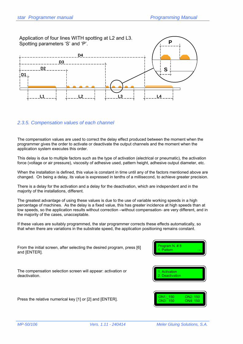
2.3.5. Compensation values of each channel The compensation values are used to correct the delay effect produced between the moment when the programmer gives the order to activate or deactivate the output channels and the moment when the application system executes this order. This delay is due to multiple factors such as the type of activation (electrical or pneumatic), the activation force (voltage or air pressure), viscosity of adhesive used, pattern height, adhesive output diameter, etc. When the installation is defined, this value is constant in time until any of the factors mentioned above are changed. On being a delay, its value is expressed in tenths of a millisecond, to achieve greater precision. There is a delay for the activation and a delay for the deactivation, which are independent and in the majority of the installations, different. The greatest advantage of using these values is due to the use of variable working speeds in a high percentage of machines. As the delay is a fixed value, this has greater incidence at high speeds than at low speeds, so the application results without correction –without compensation- are very different, and in the majority of the cases, unacceptable. If these values are suitably programmed, the star programmer corrects these effects automatically, so that when there are variations in the substrate speed, the application positioning remains constant. From the initial screen, after selecting the desired program, press [6] and [ENTER]. The compensation selection screen will appear: activation or deactivation. Press the relative numerical key [1] or [2] and [ENTER].
Program N. # 8 1. Pattern →
1. Activation 2. Deactivation
ON1:_150 ON2: 150 ON3: 150 ON4: 150
D1
D2
D3
D4
L1 L2 L3 L4
S
PAplicación de cuatro líneas CON punteado en L2 y L3.Parámetros de punteado ‘S’ y ‘P’.Application of four lines WITH spotting at L2 and L3. Spotting parameters ‘S’ and ‘P’.

star Programmer manual Programming manual
Meler Gluing Solutions, S.A. Vers. 1.11 – 240414 MP-51/106
For each output channel —1, 2, 3, or 4— we can assign a different delay value to be corrected in the activation (activation compensation ‘ON’). The same for the deactivation. For each output channel —1, 2, 3, or 4— we can assign a different delay value to be corrected in the deactivation (deactivation compensation ‘OFF’).
These values are experimental. At the end of this manual a table can be consulted for the most common installations with ‘meler’ guns.
The values are entered with the numerical keypad, confirming each value by pressing [ENTER].
The compensation values are programmed in tenths of a millisecond. A value of 150 indicates a compensation of 15 ms.
OFF1:_150 OFF2: 150 OFF3: 150 OFF4: 150
!
!

star Programmer manual Programming Manual
MP-52/106 Vers. 1.11 - 240414 Meler Gluing Solutions, S.A.
3. Restricted level The restricted level programming can be accessed by entering the relative password in the initial screen, after the presentation screens —see section ‘3.1. Front Panel’ in the ‘User Manual’—. The password is a four-figure number that the user can choose through the ‘Change password’ function —see section ‘3.1. Change restricted password’ of this manual—. The default factory defined option is ‘0000’.
If you change the password, you must take note of the new one and keep it in a safe and known place.
Enter password: ‘0000’. The first screen of the restricted level appears. The arrow to the right on the right hand side indicates that there are other options on successive screens. Press [] to advance to other available options.
[]
[] []
The arrow to the left on the right-hand side of the screen indicates that there are other options on previous screens. Press [] to be able to return to other available options.
3.1. Change restricted password On the submenu screen ‘Restricted menu’, press [1] and [ENTER]. A new screen appears. Enter the four new digits and press [ENTER]. The cursor will go to the second bracket to confirm the password chosen.
!
Restricted menu 1. Change password →
Type password Password: 0000_
2. User’s password ← 3. Phone →
3. Phone ← 4. High volt. time →
1. Change password ← 2. User’s password →
4. High volt. time ← 5. Setting encoder
Type new password ( _ ) ( )
Restricted menu 1. Change password →

star Programmer manual Programming manual
Meler Gluing Solutions, S.A. Vers. 1.11 – 240414 MP-53/106
Enter the four digits again and press [ENTER]. The password will automatically be registered. The program returns to the previous screen. If you make a mistake when entering the digits the invalidation screen appears. Press [ESC] to return to the previous screen.
Take note of the new password and keep it in a place where it can be consulted if forgotten. The programmer does not permit access if the correct password is not entered.
3.2. See user password Contrary to that set out in section ‘2.1.1. Change password’’ if the user password is lost or forgotten the process is not irreversible. For authorised personnel —those having the restricted password— this negligence can be corrected, recuperating the value of this password by reading the restricted menu. On the screen of the ‘Restricted menu’ submenu, press [2] and [ENTER]. The screen with the last user password memorised will appear —factory programmed ‘000’—.
If the restricted password has been lost or forgotten, contact the Technical Service of ‘meler’.
3.3. Change contact phone number
In the initial presentation, when the star programmer is turned on, a phone number appears to contact the ‘meler’ Technical Service. This number corresponds to the head offices in Spain. The contact number can be changed depending on the Country —or Autonomous community, in the case of Spain— where it is used. This means that the user always has the phone of the nearest Technical Service and can contact them immediately. On the ‘Restricted menu’ submenu press [3] and [ENTER].
Utilities 1. Change password →
INVALID PASSWORD Press <ESC>
!
Type new password (8888) (_ )
Restricted menu 1. Change password →
Restricted menu 1. Change password →
Password: 000
!
Restricted menu 1. Change password →

star Programmer manual Programming Manual
MP-54/106 Vers. 1.11 - 240414 Meler Gluing Solutions, S.A.
The screen to enter the new number will appear. Enter the desired number with the numerical keys and press [ENTER] to confirm. E.g. 00390542358731 (*). Press [ENTER] to change the number to the new one entered. (*) This number is fictitious and does not respond to any Technical Service of ‘meler’.
If the equipment has been installed by a ‘meler’ technician, he will have entered the correct number to contact the Technical Service of the area during the start-up.
3.4. Change High Voltage Time To speed up the application gun opening and closing response times, the voltage signal of the output channels is not a 24 Vcc amplitude rectangular wave. There is an initial high voltage ‘peak’ —of limited duration and programmable— and a ‘maintenance’ voltage below the rated 24 Vcc.
The high voltage time depends on the type of application gun used. Electric guns usually have shorter high voltage times than those ordered pneumatically by solenoid valves. To vary the high voltage time of a gun, press [4] and [ENTER] on the ‘Restricted menu’ submenu screen.
0034948351129 --------------------------
0034948351129 --------------------------
00390542358731 --------------------------
!
Restricted menu 1. Change password →
High voltage
Rated voltage
Maintenance voltage
Cycle time
High voltage time

star Programmer manual Programming manual
Meler Gluing Solutions, S.A. Vers. 1.11 – 240414 MP-55/106
The high voltage time modification screen will appear. Enter the new value with the numerical keys and press [ENTER] to confirm.
Programming longer times than necessary may cause the destruction of the activation —coil—. Shorter times may not even cause the activation.
3.5. Program the encoder setting By default the star programmer interprets each impulse received from the outside —through the encoder— as a millimetre run, so the ratio is 1:1. At times, this ratio may be different, due to the use of a different encoder to that supplied by ‘meler’ or to the installation of the encoder in places where the substrate displacement speed is not directly measured. That is why the star programmer includes a setting function for the impulses received with respect to the millimetres run. On the ‘Restricted menu’ submenu screen, press [5] and [ENTER]. The setting screen will appear. Press [] to be able to advance to other available options.
[] []
3.5.1. Set value
On this screen the ratio of impulses per millimetre used at the present time is displayed, regardless of the mode chosen to enter it. By default it will be 1:1. Press [1] and [ENTER].
High voltage time t: _ 15 ms
High voltage time t: _ 5 ms
!
Restricted menu 1. Change password
Setting encoder 1. Set value →
1. Set value ← 2. Impulses / mm →
2. Impulses / mm ← 3. Product size →
3. Product size ← 4. Line speed
Setting encoder 1. Set value →
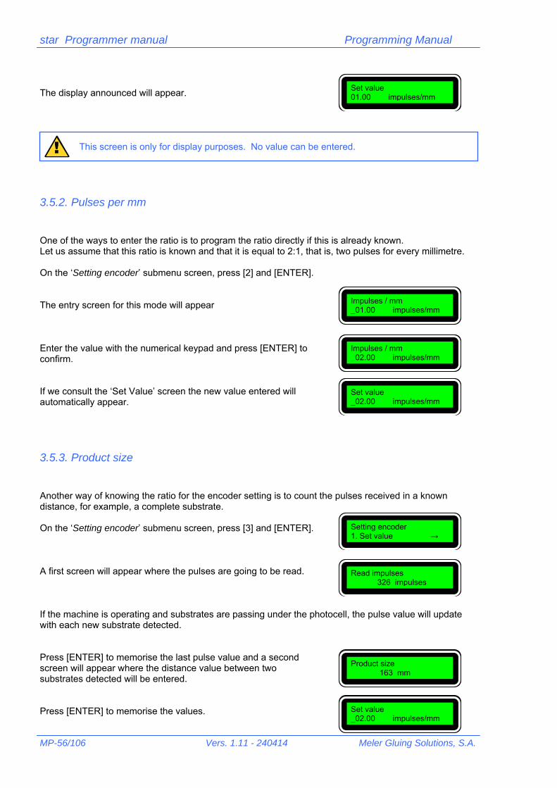
star Programmer manual Programming Manual
MP-56/106 Vers. 1.11 - 240414 Meler Gluing Solutions, S.A.
The display announced will appear.
This screen is only for display purposes. No value can be entered.
3.5.2. Pulses per mm One of the ways to enter the ratio is to program the ratio directly if this is already known. Let us assume that this ratio is known and that it is equal to 2:1, that is, two pulses for every millimetre. On the ‘Setting encoder’ submenu screen, press [2] and [ENTER]. The entry screen for this mode will appear Enter the value with the numerical keypad and press [ENTER] to confirm. If we consult the ‘Set Value’ screen the new value entered will automatically appear.
3.5.3. Product size Another way of knowing the ratio for the encoder setting is to count the pulses received in a known distance, for example, a complete substrate. On the ‘Setting encoder’ submenu screen, press [3] and [ENTER]. A first screen will appear where the pulses are going to be read. If the machine is operating and substrates are passing under the photocell, the pulse value will update with each new substrate detected. Press [ENTER] to memorise the last pulse value and a second screen will appear where the distance value between two substrates detected will be entered. Press [ENTER] to memorise the values.
Set value 01.00 impulses/mm
!
Impulses / mm _01.00 impulses/mm
Impulses / mm _02.00 impulses/mm
Set value _02.00 impulses/mm
Setting encoder 1. Set value →
Read impulses 326 impulses
Product size 163 mm
Set value _02.00 impulses/mm

star Programmer manual Programming manual
Meler Gluing Solutions, S.A. Vers. 1.11 – 240414 MP-57/106
The programmer makes the relative calculation so that if we consult the ‘Set value’ screen it will appear automatically with the new value entered.
The more exact the measurements the more exact the calculation of the pulse/mm ratio will be.
3.5.4. Line speed The third way of entering the pulse/mm ratio value is by programming the substrate displacement line speed. Using a tachometer this speed can be determined at the time of programming, and it can be entered into the programmer so that this calculates this ratio, by counting the encoder pulses. On the ‘Setting encoder’ submenu screen, press [4] and [ENTER] . The screen where the speed value is entered will appear. Press [ENTER] to memorise the data. The programmer makes the relative calculation so that if we consult the ‘Set value’ screen it will appear automatically with the new value entered.
The more exact the measurements the more exact the calculation of the pulse/mm ratio will be.
!
Setting encoder 1. Set value →
Line speed 120 m/min
Set value _02.00 impulses/mm
!

star Programmer manual Programming Manual
MP-58/106 Vers. 1.11 - 240414 Meler Gluing Solutions, S.A.
4. Programming menu tree All the screens of the star programmer are shown on the following pages as well as the access to each one of them. It is useful to have these pages at hand when programming or to consult about accessing data that we wish to change.
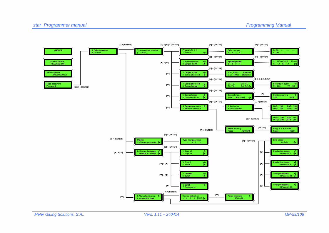
star Programmer manual Programming Manual
Meler Gluing Solutions, S.A.. Vers. 1.11 – 240414 MP-59/106
D 50 …. …. …. L 100 …. …. ….
S: _100ms/10 P: 50 mm L1 L2 L3 L4 [E]
Select output1 2 3 4
Spotting mode1 2 3 4
Min:_20Vcc 20m/minMax: 40Vcc 100m/min
O1 T:1 O2 T:1O3 T:2 O4 T:2
Control modeTime [Encoder]
1. Activation2. Deactivation
Security of cycle T1:_200 T2: 200
Continues cycle YES [NO]
ON1:_ 150 ON2: 150 ON3: 150 ON4: 150
OFF1:_ 200 OFF2: 200 OFF3: 200 OFF4: 200
Prog. N. # X erased Press [ESC]
Erase memoryPress [ENTER]
Line speed 0m/min
Production quant. 0 Pieces/h 1
Production quant. 0 Pieecs/h 2
Total production 0 Pieces1 [R]
Total production 0 Pieces2 [R]
5. Control mode6. Compensations
4. Select photocell5. Control mode
3. Output 0-10V4. Select photocell
2. Spotting mode3. Output 0-10V
Program N. # X1. Pattern
6. Compensaciones7. Borrado memoria
5. German 6. Dutch
3. French 4. Italian
1. Spanish2. English
6. Dutch 7. Portuguese
Type new password (_ ) ( )
Purge pressure 15Vcc/10
Manual activation1 2 3 4 [OFF]
Type program number( 1 - 20 ) : _
Utilities1. Change password
2. Change language3. Manual activation
3. Manual activation4. Production data
1. Select program2. Utilities
µMELER
STAR SYSTEM RELEASE 2.00
Service phone XXXXXXXXXXX
Type passwordPassword: _ [000] + [ENTER]
[1] + [ENTER]
[2] + [ENTER]
[1] a [20] + [ENTER]
[] + []
[]
[1] + [ENTER]
[2] + [ENTER]
[3] + [ENTER]
[1] + [ENTER]
[2] + [ENTER]
[3] + [ENTER]
[4] + [ENTER]
[5] + [ENTER]
[6] + [ENTER]
[7] + [ENTER]
[] + [ENTER]
[] + [ENTER]
[]+[]+[]+[]
[]
[1] + [ENTER]
[2] + [ENTER]
[ENTER]
[4] + [ENTER]
[]
[]
[]
[]
[] + []
[] + []
[] + []
[]
[][]
[]
[]
[]

star Programmer manual Programming Manual
MP-60/106 Vers. 1.11 - 240414 Meler Gluing Solutions, S.A.
2. Impulses / mm3. Product size
Type new password (_ ) ( )
[1] + [ENTER]
Restricted menu1. Change password
µMELER
STAR SYSTEM RELEASE 2.00
Service phone XXXXXXXXXXX
Type passwordPassword: _
Setting encoder1. Set value
High volt. timet: 15 ms
948351129 ------------------------
Password: 000
3. Product size4. Line speed
2. Password3. Phone no.
4. High volt. time5. Setting encoder
[0000] + [ENTER]
[2] + [ENTER]
[3] + [ENTER]
[4] + [ENTER]
[5] + [ENTER]
Set Impulses / mm0100 impulses/mm
Read impulses 312 impulses
Line speed 120 m/min
Type size 312 mm
[1] + [ENTER]
[2] + [ENTER]
[3] + [ENTER]
[4] + [ENTER]
[ENTER]
[] + []
[] + []
[] + []
[]

EXAMPLES MANUAL


star Programmer Manual Examples manual
Meler Gluing Solutions, S.A. Vers. 1.11 - 240414 ME-63/106
1. Programming examples The functions of the star programmer are explained in detail in the ‘Programming manual’ as well as how to use them. The aim of this chapter is to show practical examples of applications where these functions are used and to reveal, step by step, how they must be programmed for the specific data contained in each example.
1.1. Timer mode application. Container labelling.
1.1.1. Description. Although the greatest possibilities of the programmer can be achieved by working in the ‘Encoder’ mode, it is also possible to work in the ‘Timer’ mode, where the values entered for the application patterns are expressed in milliseconds —see section 2.2.4. ‘Select control mode / Cycle continues’ in the ‘Programming Manual’—. In some applications it is advisable to work in ‘Timer’ mode, either due to the difficulty in installing a line speed reader for the product or because of the application itself, which requires almost instantaneous response times. A typical application is ‘Container labelling’ and namely the application of a spiral or swirl on a tin. When the tin is introduced into the labelling transfer, it begins to rotate and also to move. When a photocell detects the tin —either sideways or from the top— swirling spots are instantaneously applied with self-adhesive hot-melt —the number of spots applied depends on the height of the tin—. These spots will later permit the label to be attached, wrapping it round the tin, as well as its extraction from the label-holder, with adhesive on the end edge for it to be finally attached. The schematic layout of the application may be as expressed in the figure:
v
TRANSFER BELT
CONTAINER (TIN)
GUN
REAL MOVEMENT OF TIN
SWIRL GUN

star Programmer Manual Examples manual
ME-64/106 Ed. 1.11 – 240414 Meler Gluing Solutions, S.A.
The application on the container will try to achieve, due to the characteristics of the tin used, three spiral or swirl spots, centred on the side surface. The parameters defined in a standard installation may be as follows: Distance from photocell to gun nozzle: 50 mm. Tin diameter: 70 mm. Approximate belt speed: 60 m/min. Pattern activation: three (3) applications with one (1) single solenoid valve. Swirl air activation: with independent signal solenoid valve. Analysing the data and if some rapid calculations are made, we will obtain: A photocell will be used to detect the tin connected in input ‘1’ of the star programmer. Encoder will not be used for the reasons set out at the beginning of this chapter. Two programmer outputs will be used, number ‘1’ for the adhesive applications –common solenoid valve for the three applications- and number ‘2’ for the swirl air. As the application is carried out at fixed speed, the 0-10 V signal is not used. The inhibition input of the guns must be used to prevent undesired applications due to the accidental activation of the photocell. A switch can be placed on the actual machine control to inhibit the outputs. At a speed of 60m/min, one millimetre means one millisecond. Therefore the conversion between both units is 1:1. The application delay to be programmed will be 85 mm [50+70/2], that is, 85 ms. An injection system –solenoid valve and injector module-, in non-continuous applications, takes between 5 and 10 ms to carry out a complete cycle –opening and closing-. A minimum time is required for the
application in order to achieve the greatest possible swirl concentration (see drawing). For example, the application to be programmed may initially be 15 ms. For the swirl to be effective both at the start –prevent drops of adhesive- and at the end –threads in the machines- of the application, the swirl air must be programmed so that it is activated a short time before the adhesive is applied and is deactivated shortly afterwards. Thus, the delay of the swirl air activation may be 75 ms and the activation time 25 ms, 10 ms before the start of the application and 10 ms after this has finished. In applications made in ‘Timer’ mode the programming of compensations has no effect, as it lacks an element, the encoder, which enables us to know the line speed of the machine.
OK NOK

star Programmer Manual Examples manual
Meler Gluing Solutions, S.A. Vers. 1.11 - 240414 ME-65/106
1.1.2. Connections. The programmer will have the following connections:
Connection of the power supply of the star programmer.
Photocell and gun inhibition lead connection.
Output connection for solenoid valves (1A and 2A).
1.1.3. Programming operating system. The parameters will be programmed in program 1. Turn the programmer on using the switch situated on the front panel. After the presentation screens, the password entry screen will appear. Enter password —‘000’ by default—. The first user level screen appears. From the main menu any of the twenty (20) possible programs of the star programmer can be selected. To do so, press key [1] and [ENTER], and the screen to enter the desired program appears. By default the last program selected will appear, e.g. 5.
Type password Password: 000_
1. Select program 2. Utilities
Type N. program ( 1 – 20 ) : 5
Summary of parameters to be programmed: Programming by timer. Assignment of photocell 1 to outputs 1 and 2. output 1 connector 1.A application of adhesive D (delay): 85 L (activation): 15 output 2 connector 2.A swirl air D (delay): 75 L (activation): 25

star Programmer Manual Examples manual
ME-66/106 Ed. 1.11 – 240414 Meler Gluing Solutions, S.A.
To select the program of example ‘1’, press [1] and [ENTER]. The screen will show the menu of the selected program. From the initial screen, and after selecting the desired program, press [4] and [ENTER]. The photocell assignment screen will appear (T:Trigger) for each output channel (O: Output). In channel 1 and 2 (O1, O2), we will make the selection for photocell ‘1’. Press [ENTER] to confirm. From the initial screen, after selecting the desired program, press [5] ‘Control mode’ and [ENTER]. The mode selection screen will appear. The mode between brackets is the mode currently selected. Just press [ENTER] to change from one working mode to another. The selection of the example is ‘[Time]’. Press [ESC] to go to the main menu. From the initial screen, after selecting the desired program, press [1] ‘Pattern’ and [ENTER]. The channel selection screen will appear. With keys [] and [] select channel ‘1’ and press [ENTER]. In this channel we are going to enter the adhesive pattern data. Remember: delay 85 and application time 15. With the numerical keys, enter [8], [5]. Press [] to access the application time entry position. With the numerical keys enter [1], [5]. Press [] to access the position to enter the next delay, corresponding to the second application. In this position a value appears automatically. As aid, the programmer indicates the minimum value that can be entered in this position. It corresponds to the sum of the two previous values (85, 15), adding one unit to it. This value is only valid as reference. In our case we are not going to enter any value so we press [ENTER] to confirm the data entered. The value of the second delay disappears and the data entered are stored in the memory. Press [ESC] to quit the channel selection screen. With key [] we select output ‘2’ and we press [ENTER].
Program N. # 1 1. Pattern →
01 T:1 02 T:1 03 T:2 04 T:2 →
Program N. # 1 1. Pattern →
Control mode Time [Encoder] →
Control mode [Time] Encoder →
Select output 1 2 3 4
D _ .... .... .... L .... .... .... ....
Program N. # 1 1. Pattern →
D 85 .... .... .... L …. .... .... ....
D 85 .... .... .... L 15 .... .... ....
D 85 _101 .... .... L 15 .... .... ....
D _85 …. .... .... L 15 .... .... ....
Select output 1 2 3 4

star Programmer Manual Examples manual
Meler Gluing Solutions, S.A. Vers. 1.11 - 240414 ME-67/106
In this channel we are going to enter the spiral-shape or swirl air activation data. Remember: delay 75 and application time 25. With the numerical keys enter [7], [5]. Press [] to access the position to enter the activation time. With the numerical keys, enter [2], [5]. Press [] to access the position to enter the next delay corresponding to the second application. The value appears automatically. It corresponds to the sum of the two previous values (75,25), adding one unit to it. This value is only valid as reference. In our case we are not going to enter any value so we press [ENTER] to confirm the data entered. The value of the second delay disappears and the data entered are stored in the memory. Press [ESC] to go to the channel selection screen. It is not necessary to program more data. Several tins are tested with this programming and the application and delay values are set in each case.
D _ .... .... .... L .... .... .... ....
D 75 .... .... .... L 25 .... .... ....
D 75 _101 .... .... L 25 .... .... ....
D _75 …. .... .... L 25 .... .... ....
D 75 .... .... .... L …. .... .... ....

star Programmer Manual Examples manual
ME-68/106 Ed. 1.11 – 240414 Meler Gluing Solutions, S.A.
1.2. Application using the ‘encoder’. Lockbottom carton.
1.2.1. Description. The ‘lockbottom carton’ is a very common application when making boxes. The lower part of a box is glued so that, depending on the die-casting of the box board, when unfolded it is automatically made up and ready for filling. Before being glued the box has a similar aspect to the one in the figure. The hot-melt application points are indicated on the drawing in a lighter tone.
Once glued, the box is folded for later assembly, before being filled. When assembling it, press the sides from the side, the base is automatically closed.

star Programmer Manual Examples manual
Meler Gluing Solutions, S.A. Vers. 1.11 - 240414 ME-69/106
The parameters defined in a standard installation may be as follows: Distance from photocell to gun nozzle: 0 mm (in line). Box length: 255 mm. Distance between boxes: 80 mm. Approximate speed of the belt: 100 m/min. Pattern activation: three (3) applications with three (3) solenoid valves. Bead delay 1: 100 mm. Bead length 1: 40 mm. Bead delay 2 and 3: 50 mm. Bead length 2 and 3: 15 mm.
A box detection photocell connected to input ‘1’ will be used. An encoder will be used to control the speed of the box conveyor belt to set the parameters in millimetres. Three programmer outputs will be used, number ‘1’ for the longitudinal seal bead application (bead 1), number ‘2’ for the application of the first seal bead of the bottom flap (bead 2) and number ‘3’ for the second seal bead (bead 3). The belt speed variation is assumed to be irrelevant, for the purpose of the application thickness, so 0-10V signal is not used. The activation and deactivation delays compensation function will be used.
12 3
12 3

star Programmer Manual Examples manual
ME-70/106 Ed. 1.11 – 240414 Meler Gluing Solutions, S.A.
At a speed of 100m/min, one millimetre represents 0.6 milliseconds (1 millisecond is equal to approx. 1.6 mm). Therefore the conversion between both units is 1:0.6. The smallest bead to be deposited is 15 mm, which means —according to the previous ratio— a 9 millisecond application. Given the response times of the injection system —between 5 and 10 ms— we should have no problem in achieving the length of 15 mm at a speed of 100 m/min. The activation and deactivation compensations for a standard system —gun with a double-acting injector and 24 Vcc 12.7 W solenoid— will be 9.5 and 11 ms respectively (*). (*) These are reference values, based on tests carried out under certain conditions. Any change to those conditions —temperatures, adhesives, control elements, etc.— may make these values vary.
1.2.2 Connections. The programmer will have the following connections:
Power supply connection of the star programmer.
Photocell and encoder connection.
Output connection for solenoid valves (1A, 2A and 3A).
Summary of parameters to be programmed: Encoder programming Assignment of photocell 1 to outputs 1, 2 and 3. output 1 connector 1.A bead 1 D (delay): 100 L (activation): 40 output 2 connector 2.A bead 2 D (delay): 50 L (activation): 15 output 3 connector 3.A bead 3 D (delay): 50 L (activation): 15 Compensation times: output 1 ON: 95 OFF: 110 output 2 ON: 95 OFF: 110
output 3 ON: 95 OFF: 110

star Programmer Manual Examples manual
Meler Gluing Solutions, S.A. Vers. 1.11 - 240414 ME-71/106
1.2.3. Programming operating system. The parameters will be programmed in program 6. Turn the programmer on with the switch located on the front panel. After the presentation screens, the password entry screen will appear. Enter password —‘000’ by default—. The first user level screen appears. From the main menu any of the twenty (20) possible programs that the star program has can be selected. To do so, press [1] and [ENTER], and the screen to enter the desired program will appear. By default the last program selected will flash on and off, e.g.: 1. To select the program of example ‘6’, press [6] and [ENTER]. The screen will show the menu of the program selected. From the initial screen, after selecting the desired program, press [4] and [ENTER]. The photocell assignment screen will appear (T:Trigger) for each output channel (O: Output). In channel 1, 2, and 3 (O1, O2, O3), we will make the selection for photocell ‘1’. Press [ENTER] to confirm. We press [] several times to jump to a new screen. On this screen we will program the cycle security —see chapter ‘2.2.3. Select photocell/ Cycle security’ in the ‘Programming Manual—. We enter a value corresponding to the length of the box (255 mm) plus 5 mm. This value must never exceed the sum of the length of the box (255 mm) and the space between this and the next one (80 mm). Press [2], [6], [0] —255+5— and [ENTER] to memorise the value. Press [ESC] to return to the main menu. Press [5] and [ENTER]. The mode selection screen will appear. The mode between brackets is the mode currently selected. Just press [ENTER] to change from one working mode to another. The selection of the example is ‘[Encoder]’. Press [ESC] to go to the main menu.
1. Select program 2. Utilities
Type N. # program ( 1 – 20 ) : 1
Program N. # 6 1. Pattern →
01 T:1 02 T:1 03 T:1 04 T:2 →
Control mode Time [Encoder] →
Control mode [Time] Encoder →
Program N. # 6 1. Pattern →
Security of cycle ← T1: _2 T2: 2
Security of cycle ← T1: _260 T2: 2
Program N. # 6 1. Pattern →
Type password Password: 000

star Programmer Manual Examples manual
ME-72/106 Ed. 1.11 – 240414 Meler Gluing Solutions, S.A.
From the initial screen, after selecting the desired program, press [1] and [ENTER]. The channel selection screen will appear. With the [] and [] keys select channel ‘1’ and press [ENTER]. In this channel we are going to enter the application data for bead 1. Remember: 100 delay and 40 application length. With the numerical keys enter [1], [0], [0]. Press [] to go to the position to enter the application time. With the numerical keys enter [4], [0]. Press [] to go to the position to enter the next delay, corresponding to the second application. A value automatically appears in this position. As aid, the programmer indicates the minimum value that can be entered in this position. It corresponds to the sum of the two previous values (100, 40) adding one unit to it. This value is only valid as reference. In our case we are not going to enter any value so we press [ENTER] to confirm the data entered. The value of the second delay disappears and the data entered are stored in memory. Press [ESC] to go to the channel selection screen. With [] we select output ‘2’ and press [ENTER]. In this channel we are going to enter the activation data for the second bead: Remember: 50 delay and 15 application length. With the numerical keys enter [5], [0]. Press [] to go to the position to enter the activation time. With the numerical keys, enter [1], [5]. Press [] to go to the position to enter the next delay, corresponding to the second application. The value will appear automatically. It corresponds to the sum of the two previous values (50, 159) adding one unit to it. This value is only valid as reference. In our case we are not going to enter any value so we press [ENTER] to confirm the data entered.
Output selection 1 2 3 4
D _ .... .... .... L .... .... .... ....
D 100 .... .... .... L 40 .... .... ....
D 100 _141 .... .... L 40 .... .... ....
D_100 …. .... .... L 40 .... .... ....
Select output 1 2 3 4
D _ .... .... .... L .... .... .... ....
D 50 .... .... .... L 15 .... .... ....
D 50 _66 .... .... L 15 .... .... ....
D _50 …. .... .... L 15 .... .... ....
D 50 .... .... .... L …. .... .... ....
D 100 .... .... .... L …. .... .... ....

star Programmer Manual Examples manual
Meler Gluing Solutions, S.A. Vers. 1.11 - 240414 ME-73/106
The value of the second delay disappears and the data entered are stored in the memory. Press [ESC] to go to the channel selection screen. With [] we select output ‘3’ and we press [ENTER]. In this channel we are going to enter the activation data for the third bead, identical to the second. Remember: 50 delay and 15 application length. With the numerical keys enter [5], [0]. Press [] to go to the position to enter the activation time. With the numerical keys, enter [1], [5]. Press [] to access the position to enter the next delay, corresponding to the second application. The value will appear automatically. It corresponds to the sum of the two previous values (50, 15), adding one unit to it. This value is only valid as reference. In our case we are not going to enter any value so we press [ENTER] to confirm the data entered. The value of the second delay disappears and the data entered are stored in memory. Press [ESC] to go to the channel selection screen. There are no more pattern data to be programmed. Press [ESC] to go the main screen of program ‘6’. Press [6] and [ENTER]. The compensation value assignment screen will appear. Press [1] and [ENTER]. We have to enter the delay compensation values mentioned above, expressed in tenths of a millisecond (9.5 ms – 95). So, with the [] and[] keys go to the data to be modified —in this case ‘ON1’, ‘ON2’ and ‘ON3’— and press [9], [5] and [ENTER] to memorise the value. Press [ESC], [2] and [ENTER] to access the deactivation data. Remember: enter the delay values expressed in tenths of a millisecond (11 ms – 110). So, with the[] and[ ] go to the data to be modified —in this case ‘OFF1’, ‘OFF2’ and ‘OFF3’— and press [1], [1], [0] and [ENTER] to memorise the value.
D _ .... .... .... L .... .... .... ....
D 50 .... .... .... L 15 .... .... ....
D 50 _66 .... .... L 15 .... .... ....
D _50 …. .... .... L 15 .... .... ....
D 50 .... .... .... L …. .... .... ....
Select output 1 2 3 4
Program N. # 6 1. Pattern →
1. Activation 2. Deactivation
ON1: _150 ON2: 150 ON3: 150 ON4: 150
ON1: _ 95 ON2: 95 ON3: 95 ON4: 150
OFF1: _150 OFF2: 150 OFF3: 150 OFF4: 150
OFF1: _110 OFF2: 110 OFF3: 110 OFF4: 150

star Programmer Manual Examples manual
ME-74/106 Ed. 1.11 – 240414 Meler Gluing Solutions, S.A.
It is not necessary to program more data. Several boxes are tested with this programming and the application and delay values are set in each case.

star Programmer Manual Examples manual
Meler Gluing Solutions, S.A. Vers. 1.11 - 240414 ME-75/106
1.3. Spotting examples. Bookbinding.
1.3.1. Description. The joint or groove application is a technique used in binding to achieve a better finish when gluing the end leaf to the book covers for these to open easily.
This application is made with a longitudinal bead all along the book and, at times, in bead-spotting format, with the subsequent adhesive saving. The parameters defined in a standard installation may be as follows: Distance from photocell to gun nozzle: 30 mm. Book length: 300 mm. Distance between books: 100 mm. Approximate belt speed: 60 m/min. Pattern activation: two (2) applications with two (2) solenoid valves, one for each side of the book. Bead delay: 5 mm —the value to be programmed will be the delay value plus the distance between the
photocell and gun, that is, 5+30=35—. Bead length: 290 mm. This bead will be intermittent with 10 mm spots and a pitch (start to start) between them of 20 mm. The spot must be programmed in tenths of a millisecond, therefore at 60 m/min (1mm is equal to 1 ms) 100 will be the value to be programmed. A photocell will be used to detect the books, and which will be connected in input ‘1’ of the programmer. An encoder will be used to control the speed of the book conveyor belt to set the parameters in millimetres.
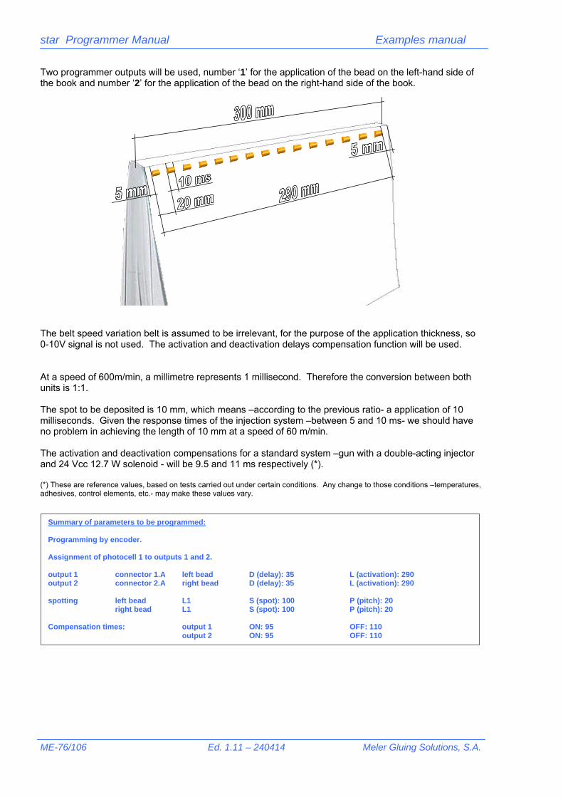
star Programmer Manual Examples manual
ME-76/106 Ed. 1.11 – 240414 Meler Gluing Solutions, S.A.
Two programmer outputs will be used, number ‘1’ for the application of the bead on the left-hand side of the book and number ‘2’ for the application of the bead on the right-hand side of the book.
The belt speed variation belt is assumed to be irrelevant, for the purpose of the application thickness, so 0-10V signal is not used. The activation and deactivation delays compensation function will be used. At a speed of 600m/min, a millimetre represents 1 millisecond. Therefore the conversion between both units is 1:1. The spot to be deposited is 10 mm, which means –according to the previous ratio- a application of 10 milliseconds. Given the response times of the injection system –between 5 and 10 ms- we should have no problem in achieving the length of 10 mm at a speed of 60 m/min. The activation and deactivation compensations for a standard system –gun with a double-acting injector and 24 Vcc 12.7 W solenoid - will be 9.5 and 11 ms respectively (*). (*) These are reference values, based on tests carried out under certain conditions. Any change to those conditions –temperatures, adhesives, control elements, etc.- may make these values vary.
Summary of parameters to be programmed: Programming by encoder. Assignment of photocell 1 to outputs 1 and 2. output 1 connector 1.A left bead D (delay): 35 L (activation): 290 output 2 connector 2.A right bead D (delay): 35 L (activation): 290 spotting left bead L1 S (spot): 100 P (pitch): 20 right bead L1 S (spot): 100 P (pitch): 20 Compensation times: output 1 ON: 95 OFF: 110 output 2 ON: 95 OFF: 110

star Programmer Manual Examples manual
Meler Gluing Solutions, S.A. Vers. 1.11 - 240414 ME-77/106
1.3.2. Connections. The programmer will have the following connections:
Power supply connection of the star programmer
Photocell and encoder connection
Output connection for solenoid valves (1A and 2A).
Two different channels are chosen –1A and 2A- to be able to set the beads independently. If the exact alignment of the two guns –one on each side- is guaranteed, one single channel could be used —1A and 1B—.
1.3.3. Programming operating system. The parameters will be programmed in program 1. Turn the programmer on with the switch located on the front panel. After the presentation screens, the password entry screen will appear. Enter password —‘000’ by default—. The first user level screen appears. From the main menu any of the twenty (20) possible programs that the star program has can be selected. To do so, press [1] and [ENTER], and the screen to enter the desired program will appear. By default the last program selected will flash on and off, e.g.: 3.
1. Select program 2. Utilities
Type N. # program ( 1 – 20 ) : 3
Type password Password: 000
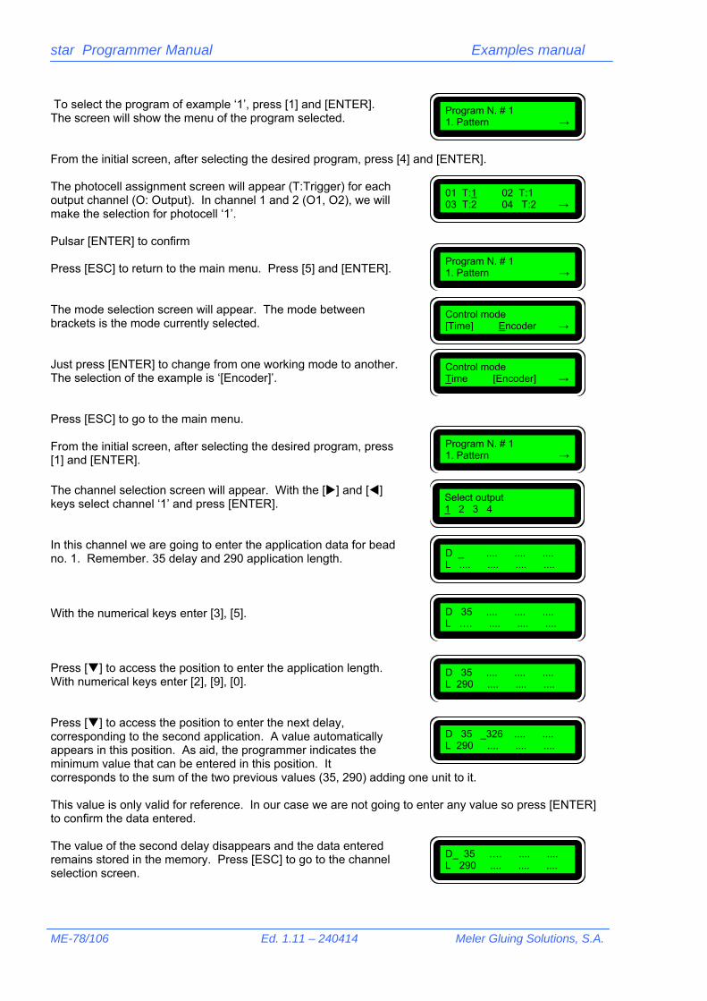
star Programmer Manual Examples manual
ME-78/106 Ed. 1.11 – 240414 Meler Gluing Solutions, S.A.
To select the program of example ‘1’, press [1] and [ENTER]. The screen will show the menu of the program selected. From the initial screen, after selecting the desired program, press [4] and [ENTER]. The photocell assignment screen will appear (T:Trigger) for each output channel (O: Output). In channel 1 and 2 (O1, O2), we will make the selection for photocell ‘1’. Pulsar [ENTER] to confirm Press [ESC] to return to the main menu. Press [5] and [ENTER]. The mode selection screen will appear. The mode between brackets is the mode currently selected. Just press [ENTER] to change from one working mode to another. The selection of the example is ‘[Encoder]’. Press [ESC] to go to the main menu. From the initial screen, after selecting the desired program, press [1] and [ENTER]. The channel selection screen will appear. With the [] and [] keys select channel ‘1’ and press [ENTER]. In this channel we are going to enter the application data for bead no. 1. Remember. 35 delay and 290 application length. With the numerical keys enter [3], [5]. Press [] to access the position to enter the application length. With numerical keys enter [2], [9], [0]. Press [] to access the position to enter the next delay, corresponding to the second application. A value automatically appears in this position. As aid, the programmer indicates the minimum value that can be entered in this position. It corresponds to the sum of the two previous values (35, 290) adding one unit to it. This value is only valid for reference. In our case we are not going to enter any value so press [ENTER] to confirm the data entered. The value of the second delay disappears and the data entered remains stored in the memory. Press [ESC] to go to the channel selection screen.
Program N. # 1 1. Pattern →
01 T:1 02 T:1 03 T:2 04 T:2 →
Control mode Time [Encoder] →
Control mode [Time] Encoder →
Select output 1 2 3 4
D _ .... .... .... L .... .... .... ....
Program N. # 1 1. Pattern →
Program N. # 1 1. Pattern →
D 35 .... .... .... L 290 .... .... ....
D 35 _326 .... .... L 290 .... .... ....
D_ 35 …. .... .... L 290 .... .... ....
D 35 .... .... .... L …. .... .... ....

star Programmer Manual Examples manual
Meler Gluing Solutions, S.A. Vers. 1.11 - 240414 ME-79/106
With the [] key we select output ‘2’ and we press [ENTER]. We repeat the previous steps as the bead must be the same, unless there are adjustments. After programming the data we return to the initial screen. Press [2] and [ENTER]. The spotting mode screen is reached. A different spotting mode can be selected for each channel For channel 1, with the [] key, we select output ‘1’ and we press [ENTER]. The values to be programmed are S:100 and P: 20. With the numerical keys enter [1], [0], [0]. With the [] key select parameter ‘P’ and enter the value [2], [0]. As each programmer output can apply up to four (4) strips of adhesive, the strip or strips we wish to spot must be selected. In this case only one strip. With [] select L1’ and press [ENTER]. An asterisk will appear next to the selection, indicating that it has been selected. The data is validated by selecting ‘E’ and pressing [ENTER]. Press [ESC] to go to the previous screen. We repeat the steps for output ‘2’. After programming the data we return to the initial screen. If we now access the output selection menu[1], [ENTER] the letter ‘S’ appears next to output 1 and 2, indicating that the spotting mode function has been activated for these two outputs. Press [ESC] to access the main screen of the program. Press [6] and [ENTER]. The compensation values assignment screen will appear. Press [1] and [ENTER]. We have to enter the delay compensation values mentioned above, expressed in tenths of a millisecond (9.5 ms – 95). So, with the [] and[] keys go to the data to be modified —in this case ‘ON1’ and ‘ON2’— and press [9], [5] and [ENTER] to memorise the value.
Select output 1 2 3 4
D _ .... .... .... L .... .... .... ....
Program N. # 1 1. Pattern →
Spotting mode 1 2 3 4
S: _100ms/10 P: 50 mm L1 L2 L3 L4 [E]
S: _100ms/10 P: 20 mm L1 L2 L3 L4 [E]
S: _100ms/10 P: 20 mm L1* L2 L3 L4 [E]
Spotting mode 1 2 3 4
Program N. # 1 1. Pattern →
Select output 1S 2S 3 4
1. Activation 2. Deactivation
ON1: _150 ON2: 150 ON3: 150 ON4: 150
ON1: _ 95 ON2: 95 ON3: 150 ON4: 150
Program N. # 1 1. Pattern →

star Programmer Manual Examples manual
ME-80/106 Ed. 1.11 – 240414 Meler Gluing Solutions, S.A.
!
Press [ESC], [2] and [ENTER] to access the deactivation data. Remember: enter the delay values expressed in tenths of a millisecond (11 ms – 110). So, with the [] and[ ] keys go to the data to be modified —in this case ‘OFF1’ and ‘OFF2’— and press [1], [1], [0] and [ENTER] to memorise the value It is not necessary to program more data. Several books are tested with this programming and the application and delay values are set, as well as the spotting mode and compensation values.
A spotting value greater than the pitch value cannot be programmed. Remember, at 60 m/min a millimetre is equal to one millisecond.
OFF1: _150 OFF2: 150 OFF3: 150 OFF4: 150
OFF1: _110 OFF2: 110 OFF3: 150 OFF4: 150

star Programmer Manual Examples manual
Meler Gluing Solutions, S.A. Vers. 1.11 - 240414 ME-81/106
1.4. Use of the cycle security.
1.4.1. Description. The cycle security consists of giving a value to a parameter that enables us to annul, as from the first photocell detection, any new detection, whilst the value specified in that parameter lasts. During the time the application is maintained, the shape, texture or material of the substrate can cause undesired cycle starts. The cycle security parameter guarantees that this is not going to occur until the value indicated in the parameter, namely the length of the substrate, has elapsed. For example, in a box with a certain depth, you wish to apply an adhesive bead on the inside to glue a dividing wall, for example. It will start by reading the front edge, but, after the application cycle has ended, a new cycle will begin when it detects the rear edge.
The distance between photocell and gun is 5 mm. The length of the box is 250 mm, the start delay 10 mm and the application bead length is 230 mm.
To be sure that the photocell will be cancelled when it passes over the rear edge, a value is chosen for the ‘cycle security’ parameter of 255 mm (length of the box – 250 mm – plus 5 mm tolerance). These 5 mm depend on the separation that exists between two boxes and can be increased if the distance between them is sufficient. A photocell will be used to detect the boxes connected in the input ‘1’ of the programmer. An encoder will be used to control the box conveyor belt speed to set the parameters in millimetres. A programmer output, number ‘1’, will be used to apply the bead.
10 230
250
10 230
250

star Programmer Manual Examples manual
ME-82/106 Ed. 1.11 – 240414 Meler Gluing Solutions, S.A.
1.4.2. Connections. The programmer will have the following connections:
Power supply connection of the star programmer.
Photocell and encoder connection.
Output connection for solenoid valve (1A)
1.4.3. Programming operating system The parameters will be programmed in program 8. Turn the programmer on with the switch located on the front panel. After the presentation screens, the password entry screen will appear. Enter password —‘000’ by default—. The first user level screen appears. From the main menu any of the twenty (20) possible programs that the star program has can be selected.
Type password Password: 000_
1. Select program 2. Utilities
Summary of parameters to be programmed: Programming by encoder. Assignment of photocell 1 to output 1. output 1 connector 1.A bead D (delay): 15 L (activation): 230 Cycle security: 255 (5 mm greater than the length of the box) Compensation times: output 1 ON: 95 OFF: 110

star Programmer Manual Examples manual
Meler Gluing Solutions, S.A. Vers. 1.11 - 240414 ME-83/106
To do so, press [1] and [ENTER], and the screen to enter the desired program will appear. By default the last program selected will flash on and off, e.g.: 3. To select the program of example ‘8’, press [8] and [ENTER]. The screen will show the menu of the program selected. From the initial screen, after selecting the desired program, press [4] and [ENTER]. The photocell assignment screen will appear (T:Trigger) for each output channel (O: Output). In channel 1 (O1), we will make the selection for photocell ‘1’. Press [ENTER] to confirm. We press [] several times to jump to a new screen. On this screen we will program the security of cycle —see chapter ‘2.2.3. Select photocell/Security of cycle’ in the ‘Programming manual’—. We enter the relative value (255 mm). Press [2], [5], [5] and [ENTER] to memorise the value. Press [ESC] to return to the main menu. Press [5] and [ENTER]. The mode selection screen will appear. The mode between brackets is the mode currently selected. Just press [ENTER] to change from one working mode to another. The selection of the example is ‘[Encoder]’. Press [ESC] to go to the main menu. From the initial screen, after selecting the desired program, press [1] and [ENTER]. The channel selection screen will appear. With the [] and [] keys select channel ‘1’ and press [ENTER]. In this channel we are going to enter the application data for no. 1. Remember. 15 delay and 230 application length. With the numerical keys enter [1], [5].
01 T:1 02 T:1 03 T:1 04 T:2 →
Control mode Time [Encoder] →
Select output 1 2 3 4
D _ .... .... .... L .... .... .... ....
Program N. # 8 1. Pattern →
Security of cycle ← T1: _2 T2: 2
Security of cycle ← T1: _255 T2: 2
Program N. # 8 1. Pattern →
Type program number ( 1 – 20 ) : 3
Program N. # 8 1. Pattern →
D 15 .... .... .... L …. .... .... ....
Control mode [Time] Encoder →
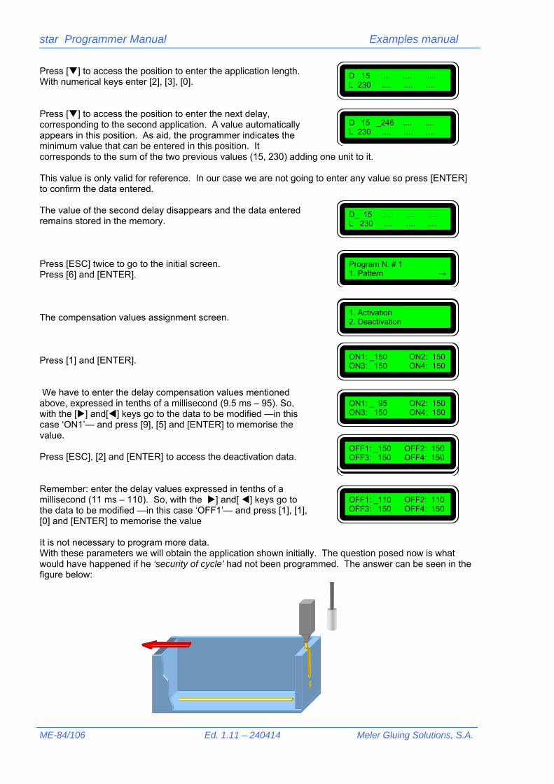
star Programmer Manual Examples manual
ME-84/106 Ed. 1.11 – 240414 Meler Gluing Solutions, S.A.
Press [] to access the position to enter the application length. With numerical keys enter [2], [3], [0]. Press [] to access the position to enter the next delay, corresponding to the second application. A value automatically appears in this position. As aid, the programmer indicates the minimum value that can be entered in this position. It corresponds to the sum of the two previous values (15, 230) adding one unit to it. This value is only valid for reference. In our case we are not going to enter any value so press [ENTER] to confirm the data entered. The value of the second delay disappears and the data entered remains stored in the memory. Press [ESC] twice to go to the initial screen. Press [6] and [ENTER]. The compensation values assignment screen. Press [1] and [ENTER]. We have to enter the delay compensation values mentioned above, expressed in tenths of a millisecond (9.5 ms – 95). So, with the [] and[] keys go to the data to be modified —in this case ‘ON1’— and press [9], [5] and [ENTER] to memorise the value. Press [ESC], [2] and [ENTER] to access the deactivation data. Remember: enter the delay values expressed in tenths of a millisecond (11 ms – 110). So, with the ] and[ ] keys go to the data to be modified —in this case ‘OFF1’— and press [1], [1], [0] and [ENTER] to memorise the value It is not necessary to program more data. With these parameters we will obtain the application shown initially. The question posed now is what would have happened if he ‘security of cycle’ had not been programmed. The answer can be seen in the figure below:
D 15 .... .... .... L 230 .... .... ....
D 15 _246 .... .... L 230 .... .... ....
D_ 15 …. .... .... L 230 .... .... ....
Program N. # 1 1. Pattern →
1. Activation 2. Deactivation
ON1: _150 ON2: 150 ON3: 150 ON4: 150
ON1: _ 95 ON2: 150 ON3: 150 ON4: 150
OFF1: _150 OFF2: 150 OFF3: 150 OFF4: 150
OFF1: _150 OFF2: 150 OFF3: 150 OFF4: 150
OFF1: _110 OFF2: 110 OFF3: 150 OFF4: 150

star Programmer Manual Examples manual
Meler Gluing Solutions, S.A. Vers. 1.11 - 240414 ME-85/106
1.5. Use of the 0-10 V signal. Sift-proof.
1.5.1. Description. A frequent application, in certain sectors of the industry, is the ‘hermetic’ or ‘sift-proof’ sealing of boxes, applicable to any granulated or dusty product. These products have traditionally been packed in sealed bags to prevent the product from coming out. By sealing the box with the multi-strip based system application, a sift-proof seal is achieved. The adhesive application on the box can be seen in the figure.
The system is comprised of two equal applications –sometimes symmetrical, depending on the layout of the injectors-, one for the lower seal of the box, before being refilled, and another for the upper seal, after dispensing the exact quantity of product. When the outer lid is finally pressed, the adhesive application creates a closed ring of adhesive, which totally isolates the product from the outside. The guns, of a variable design depending on the size of the box, have an injector with an independent control, which applies the longest bead, and the other injectors with one or several controls, which apply the shortest beads. In general, it may be sufficient to use only two controls and this is what will be considered in this example. In the figure on the next page you can see a ‘standard’ layout of multi-strip nozzles and the resulting application on the box. This example is used, as stated in the title, for the use of the 0-10V signal. More information can be obtained about this function in the ‘Programming Manual’ —see chapter ‘2.2.2. 0-10 Control values’—.

star Programmer Manual Examples manual
ME-86/106 Ed. 1.11 – 240414 Meler Gluing Solutions, S.A.
If, in an multi-strip application —and in general for any application— we obviously increase or decrease the machine speed, the application beads are affected in two different ways:
- in their length and position - in their thickness The first aspect is solved by the delay compensations function —see ‘Programming Manual’ and its chapter ‘2.3.5 Compensation values of each channel’— already used in previous examples. The second aspect is solved by using a pressure variator device —proportional valve— in piston equipment or by means of motor speed variators for gearing equipment. In both cases a set-point signal is required which, depending on the speed of the machine, transmits the relative order to the variator to set the relative parameter —pressure or speed—. This necessary setting, between machine speed values and pressure values or applicator equipment rotation speed is carried out by the ‘Output 0-10V’ function.
The parameters defined in an installation of this kind can be the following: Distance from photocell to gun nozzle: 25 mm. Box length: 100 mm. Distance between boxes: 100 mm. Approximate belt speed: between 40 m/min and 80 m/min. Pattern activation: two (2) applications with two (2) solenoid valves, for each gun —lower seal / upper seal—. Long bead delay: 5 mm —the value to be programmed will be the delay plus the distance between photocell and gun, that is, 5+25=30—. Long bead length: 90 mm. Delay of first strip of small beads: 5 mm —value to be programmed, 5+25=30—. Length of first strip of small beads: 12 mm Delay of second strip of small beads: 83 mm —value to be programmed, 83+25=108—. Length of second strip of small beads: 12 mm Two photocells will be used to detect the boxes, which are connected in inputs ‘1’ and ‘2’ of the programmer.

star Programmer Manual Examples manual
Meler Gluing Solutions, S.A. Vers. 1.11 - 240414 ME-87/106
An encoder will be used to control the speed of the box conveyor belt to set the parameters in millimetres and for the 0-10V signal. Four programmer outputs will be used, number ‘1’ and ‘3’ for the application of the long beads and numbers ‘2’ and ‘4’ for the small beads. At a speed of 40 m/min, 1 millimetre is equal to 1.6 milliseconds (1 millisecond is equal to 0.6 mm). Therefore the conversion between both units is 1:1.6. At a speed of 80 m/min, 1 millimetre is equal to 0.77 milliseconds (1 millisecond is equal to 1.3 mm). Therefore the conversion between both units is 1:0.77. The smallest bead to be deposited is 12 mm, which means —according to the previous ratios— a application between 9 and 19 milliseconds. Given the response times of the injector system —between 5 and 10 ms— we should have no problem in achieving the length of 12 mm at speeds of 40÷80 m/min. The activation and deactivation compensations for a standard system —gun with double-acting injector and 24 Vcc 12.7 W solenoid valve— will be 9.5 and 11 ms respectively (*). (*) These values are for reference, based on tests performed under certain conditions. Any change to these conditions —temperatures, adhesives, control elements, etc.— may make these values vary.
1.5.2. Connections. The programmer will have the following connections:
Connection of the power supply of the star programmer
Connection of two photocells –upper connectors-. Connection of encoder and 0-10V signal –lower connectors-.
Summary of parameters to be programmed: Programming by encoder. Assignment of photocell 1 to outputs 1 and 2, and photocell 2 to outputs 3 and 4. output 1 connector 1.A low. long bead D (delay): 30 L (activation): 90 output 2 connector 2.A low. small bead D1 (delay): 30 L1 (activation): 12 D2: 108 L2: 12 output 3 connector 3.A upp. long bead D (delay): 30 L (activation): 90 output 4 connector 4.A upp. small bead D1 (delay): 30 L1 (activation): 12 D2: 108 L2: 12 Compensation times: output 1 ON: 95 OFF: 110
output 2 ON: 95 OFF: 110 output 3 ON: 95 OFF: 110 output 4 ON: 95 OFF: 110
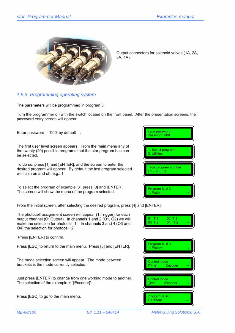
star Programmer Manual Examples manual
ME-88/106 Ed. 1.11 – 240414 Meler Gluing Solutions, S.A.
Output connectors for solenoid valves (1A, 2A, 3A, 4A).
1.5.3. Programming operating system The parameters will be programmed in program 3. Turn the programmer on with the switch located on the front panel. After the presentation screens, the password entry screen will appear Enter password —‘000’ by default—. The first user level screen appears. From the main menu any of the twenty (20) possible programs that the star program has can be selected. To do so, press [1] and [ENTER], and the screen to enter the desired program will appear. By default the last program selected will flash on and off, e.g.: 1 To select the program of example ‘3’, press [3] and [ENTER]. The screen will show the menu of the program selected. From the initial screen, after selecting the desired program, press [4] and [ENTER]. The photocell assignment screen will appear (T:Trigger) for each output channel (O: Output). In channels 1 and 2 (O1, O2) we will make the selection for photocell ‘1’. In channels 3 and 4 (O3 and O4) the selection for photocell ‘2’. Press [ENTER] to confirm. Press [ESC] to return to the main menu. Press [5] and [ENTER]. The mode selection screen will appear. The mode between brackets is the mode currently selected. Just press [ENTER] to change from one working mode to another. The selection of the example is ‘[Encoder]’. Press [ESC] to go to the main menu.
Type password Password: 000_
1. Select program 2. Utilities
Type program number ( 1 – 20 ) : 1
Program N. # 3 1. Pattern →
01 T:1 02 T:1 03 T:2 04 T:2 →
Control mode Time [Encoder] →
Control mode [Time] Encoder →
Program N. # 3 1. Pattern →
Program N. # 3 1. Pattern →
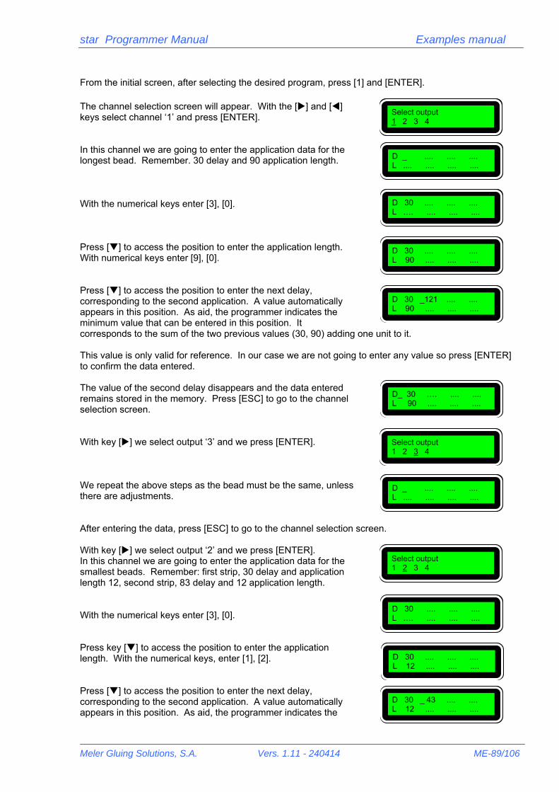
star Programmer Manual Examples manual
Meler Gluing Solutions, S.A. Vers. 1.11 - 240414 ME-89/106
From the initial screen, after selecting the desired program, press [1] and [ENTER]. The channel selection screen will appear. With the [] and [] keys select channel ‘1’ and press [ENTER]. In this channel we are going to enter the application data for the longest bead. Remember. 30 delay and 90 application length. With the numerical keys enter [3], [0]. Press [] to access the position to enter the application length. With numerical keys enter [9], [0]. Press [] to access the position to enter the next delay, corresponding to the second application. A value automatically appears in this position. As aid, the programmer indicates the minimum value that can be entered in this position. It corresponds to the sum of the two previous values (30, 90) adding one unit to it. This value is only valid for reference. In our case we are not going to enter any value so press [ENTER] to confirm the data entered. The value of the second delay disappears and the data entered remains stored in the memory. Press [ESC] to go to the channel selection screen. With key [] we select output ‘3’ and we press [ENTER]. We repeat the above steps as the bead must be the same, unless there are adjustments. After entering the data, press [ESC] to go to the channel selection screen. With key [] we select output ‘2’ and we press [ENTER]. In this channel we are going to enter the application data for the smallest beads. Remember: first strip, 30 delay and application length 12, second strip, 83 delay and 12 application length. With the numerical keys enter [3], [0]. Press key [] to access the position to enter the application length. With the numerical keys, enter [1], [2]. Press [] to access the position to enter the next delay, corresponding to the second application. A value automatically appears in this position. As aid, the programmer indicates the
Select output 1 2 3 4
D _ .... .... .... L .... .... .... ....
D 30 .... .... .... L 90 .... .... ....
D 30 _121 .... .... L 90 .... .... ....
D_ 30 …. .... .... L 90 .... .... ....
Select output 1 2 3 4
D _ .... .... .... L .... .... .... ....
D 30 .... .... .... L …. .... .... ....
Select output 1 2 3 4
D 30 .... .... .... L 12 .... .... ....
D 30 _ 43 .... .... L 12 .... .... ....
D 30 .... .... .... L …. .... .... ....
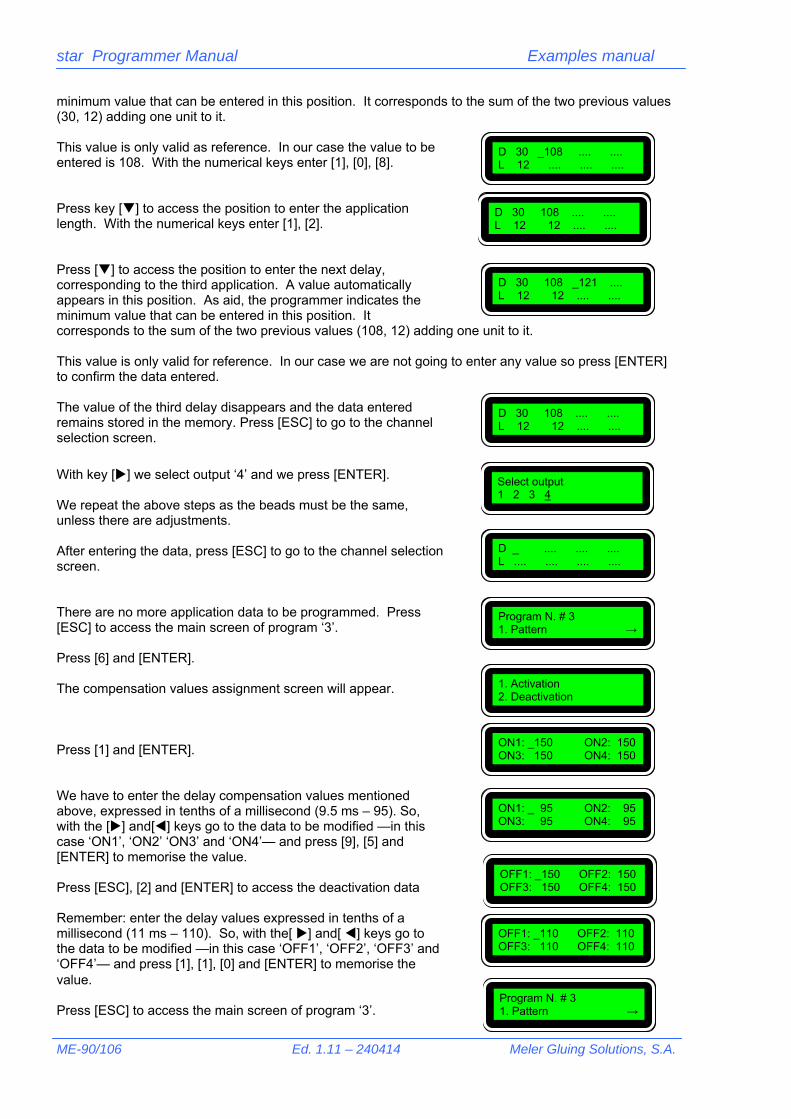
star Programmer Manual Examples manual
ME-90/106 Ed. 1.11 – 240414 Meler Gluing Solutions, S.A.
minimum value that can be entered in this position. It corresponds to the sum of the two previous values (30, 12) adding one unit to it. This value is only valid as reference. In our case the value to be entered is 108. With the numerical keys enter [1], [0], [8]. Press key [] to access the position to enter the application length. With the numerical keys enter [1], [2]. Press [] to access the position to enter the next delay, corresponding to the third application. A value automatically appears in this position. As aid, the programmer indicates the minimum value that can be entered in this position. It corresponds to the sum of the two previous values (108, 12) adding one unit to it. This value is only valid for reference. In our case we are not going to enter any value so press [ENTER] to confirm the data entered. The value of the third delay disappears and the data entered remains stored in the memory. Press [ESC] to go to the channel selection screen.
With key [] we select output ‘4’ and we press [ENTER]. We repeat the above steps as the beads must be the same, unless there are adjustments. After entering the data, press [ESC] to go to the channel selection screen. There are no more application data to be programmed. Press [ESC] to access the main screen of program ‘3’. Press [6] and [ENTER]. The compensation values assignment screen will appear. Press [1] and [ENTER]. We have to enter the delay compensation values mentioned above, expressed in tenths of a millisecond (9.5 ms – 95). So, with the [] and[] keys go to the data to be modified —in this case ‘ON1’, ‘ON2’ ‘ON3’ and ‘ON4’— and press [9], [5] and [ENTER] to memorise the value. Press [ESC], [2] and [ENTER] to access the deactivation data Remember: enter the delay values expressed in tenths of a millisecond (11 ms – 110). So, with the[ ] and[ ] keys go to the data to be modified —in this case ‘OFF1’, ‘OFF2’, ‘OFF3’ and ‘OFF4’— and press [1], [1], [0] and [ENTER] to memorise the value. Press [ESC] to access the main screen of program ‘3’.
D 30 _108 .... .... L 12 .... .... ....
D 30 108 .... .... L 12 12 .... ....
D 30 108 _121 .... L 12 12 .... ....
Select output 1 2 3 4
D _ .... .... .... L .... .... .... ....
D 30 108 .... .... L 12 12 .... ....
1. Activation 2. Deactivation
ON1: _150 ON2: 150 ON3: 150 ON4: 150
ON1: _ 95 ON2: 95 ON3: 95 ON4: 95
OFF1: _150 OFF2: 150 OFF3: 150 OFF4: 150
OFF1: _110 OFF2: 110 OFF3: 110 OFF4: 110
Program N. # 3 1. Pattern →
Program N. # 3 1. Pattern →

star Programmer Manual Examples manual
Meler Gluing Solutions, S.A. Vers. 1.11 - 240414 ME-91/106
!
Press [3] and [ENTER]. The 0-10V signal setting screen will appear. The voltage values are expressed in tenths of a volt, therefore the current situation is 0 volts when the machine is stopped (this would correspond to 0 bar pressure or to 0 rpm, depending on the equipment) and 10 volts when the machine has a speed of 400 m/min (corresponding to maximum pressure —standard 6 bar— or to maximum rpm —100—). The way to enter these values is based on setting the voltages to the maximum and minimum work speeds. The other values are automatically interpolated by the star programmer. Therefore, with the machine at maximum working speed, it is set by entering a suitable value in the ‘Max’ parameter and visually verifying that the thickness of the bead deposited is as desired. For example, we enter [6], [5] (6.5 V) and press [ENTER]. The speed it is working at and for which the voltage value has been set, is immediately displayed, 80 m/min. After setting this value, the operation is repeated for the minimum working speed value (40 m/min). For example, we enter [2], [8] (2.8 V) and press [ENTER]. The speed it is working at and for which the voltage value has been set, is immediately displayed, 40 m/min.
Speed values cannot be entered. These values appear automatically when [ENTER] is pressed, after having entered a voltage value.
The final situation, expressed in a graph, would be as follows:
Min: _ 0Vcc 0m/min Max: 100Vcc 400m/min
Min: _ 0Vcc 0m/min Max: 65Vcc 80m/min
Min: _ 28Vcc 40m/min Max: 65Vcc 80m/min

star Programmer Manual Examples manual
ME-92/106 Ed. 1.11 – 240414 Meler Gluing Solutions, S.A.
1.6. Compensation application. Longitudinal bead
1.6.1. Description. The longitudinal bead is used in any case-type box to form the box before it is filled and later sealed. A bead of adhesive is applied to one of the flaps, which is glued to the opposite end, thus forming the box.
The application is simple; its difficulty lies in the fact that these cases are usually processed at high and variable machine speeds, around 120 to 150 m/min. Under these conditions, the accuracy of the application is essential and it is not possible for the bead to move due to variations in the machine speed. For these cases the correct use of the delay compensation function of the system is essential. The parameters defined in a standard installation may be as follows:
Distance from photocell to gun nozzle: 30 mm. Box length: 160 mm. Distance between boxes: 40 mm. Approximate belt speed: between 120 m/min and 150 m/min. Pattern activation: one (1) application with one (1) solenoid valve.
Bead delay: 20 mm —the value to be programmed will be the delay plus the distance between photocell
and gun, that is, 20+30=50—. Bead length: 120 mm.
20
120
20
120

star Programmer Manual Examples manual
Meler Gluing Solutions, S.A. Vers. 1.11 - 240414 ME-93/106
A photocell will be used to detect the boxes, which is connected in input ‘1’ of the programmer. An encode will be used to control the sped of the box conveyor belt to set the parameters in millimetres. One of the programmer outputs will be used, number ‘1’. At a speed of 120 m/min, 1 millimetre is equal to 0.5 milliseconds (1 millisecond is equal to 2 mm). Therefore the conversion between both units is 1:0.5. At a speed of 150 m/min, 1 millimetre is equal to 0.4 milliseconds (1 millisecond is equal to 2.5 mm). Therefore the conversion between both units is 1:0.4. The bead to be deposited is 120 mm, which means –according to the previous ratios- an application of between 48 and 60 milliseconds. Given the response times of the injector system –between 5 and 10 ms- we should have no problem in achieving the length of 120 mm at speeds of 120÷150 m/min. The activation and deactivation compensations for a standard system –gun with double-acting injector and 24 Vcc 12.7 W solenoid valve- will be 9.5 and 11 ms respectively (*). (*) These values are for reference, based on tests performed under certain conditions. Any change to these conditions –temperatures, adhesives, control elements, etc.- may make these values vary.
1.6.2. Connections. The programmer will have the following connections:
Connection of the power supply of the star programmer.
Photocell and encoder connection.
Output connection for solenoid valve (1A)
Summary of parameters to be programmed: Programming by encoder. Assignment of photocell 1 to output 1. output 1 connector 1.A longitudinal bead D (delay): 50 L (activation): 120 Compensation times: output 1 ON: 95 OFF: 110
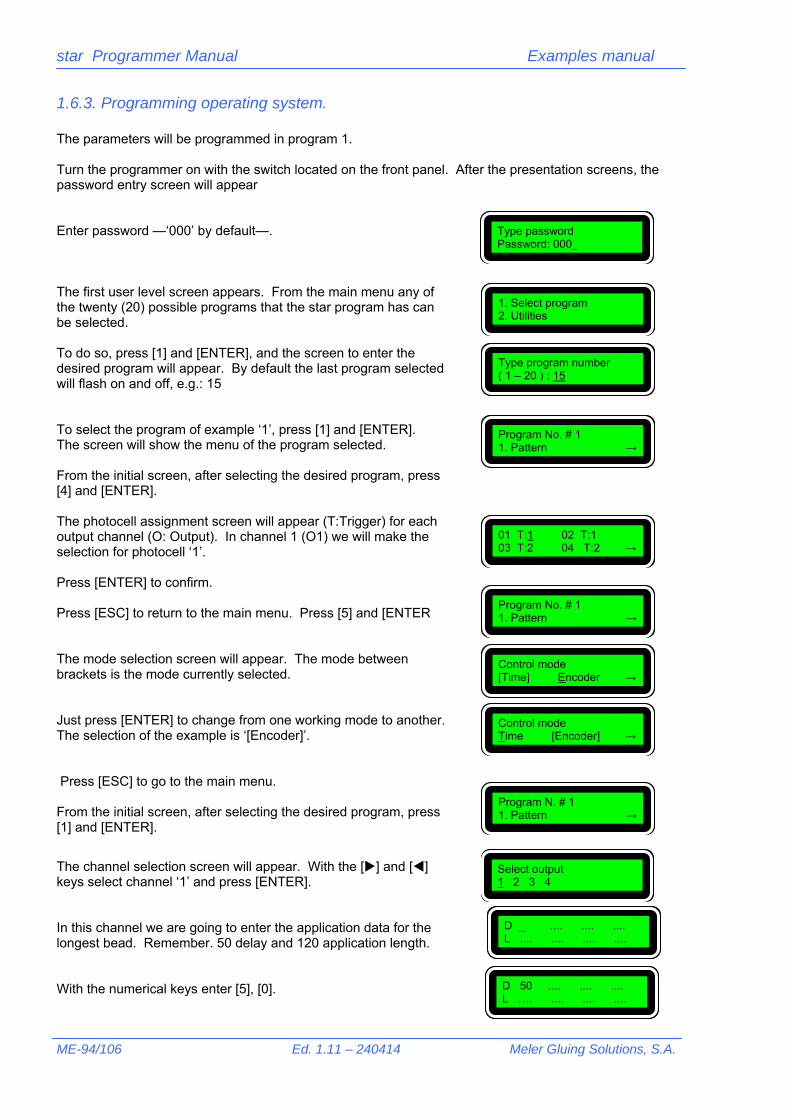
star Programmer Manual Examples manual
ME-94/106 Ed. 1.11 – 240414 Meler Gluing Solutions, S.A.
1.6.3. Programming operating system. The parameters will be programmed in program 1. Turn the programmer on with the switch located on the front panel. After the presentation screens, the password entry screen will appear Enter password —‘000’ by default—. The first user level screen appears. From the main menu any of the twenty (20) possible programs that the star program has can be selected. To do so, press [1] and [ENTER], and the screen to enter the desired program will appear. By default the last program selected will flash on and off, e.g.: 15 To select the program of example ‘1’, press [1] and [ENTER]. The screen will show the menu of the program selected. From the initial screen, after selecting the desired program, press [4] and [ENTER]. The photocell assignment screen will appear (T:Trigger) for each output channel (O: Output). In channel 1 (O1) we will make the selection for photocell ‘1’. Press [ENTER] to confirm. Press [ESC] to return to the main menu. Press [5] and [ENTER The mode selection screen will appear. The mode between brackets is the mode currently selected. Just press [ENTER] to change from one working mode to another. The selection of the example is ‘[Encoder]’. Press [ESC] to go to the main menu. From the initial screen, after selecting the desired program, press [1] and [ENTER].
The channel selection screen will appear. With the [] and [] keys select channel ‘1’ and press [ENTER]. In this channel we are going to enter the application data for the longest bead. Remember. 50 delay and 120 application length. With the numerical keys enter [5], [0].
Type password Password: 000_
1. Select program 2. Utilities
Type program number ( 1 – 20 ) : 15
Program No. # 1 1. Pattern →
01 T:1 02 T:1 03 T:2 04 T:2 →
Control mode Time [Encoder] →
Control mode [Time] Encoder →
Select output 1 2 3 4
D _ .... .... .... L .... .... .... ....
Program N. # 1 1. Pattern →
Program No. # 1 1. Pattern →
D 50 .... .... .... L …. .... .... ....
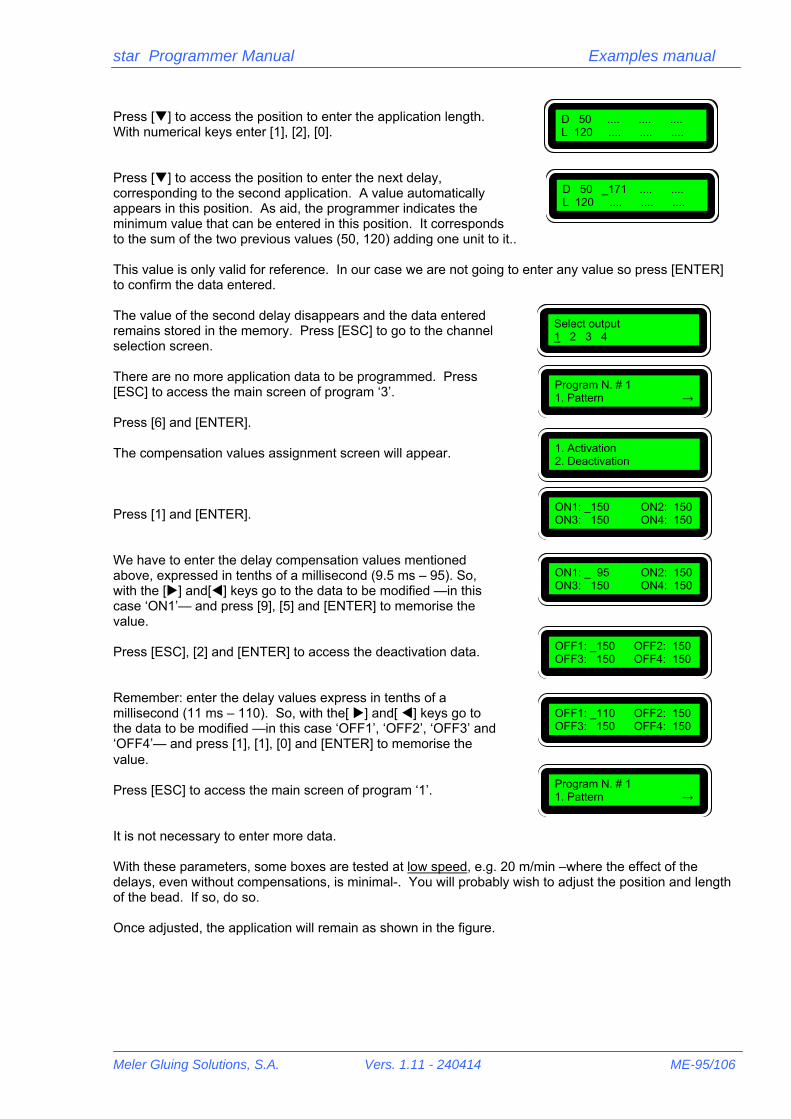
star Programmer Manual Examples manual
Meler Gluing Solutions, S.A. Vers. 1.11 - 240414 ME-95/106
Press [] to access the position to enter the application length. With numerical keys enter [1], [2], [0]. Press [] to access the position to enter the next delay, corresponding to the second application. A value automatically appears in this position. As aid, the programmer indicates the minimum value that can be entered in this position. It corresponds to the sum of the two previous values (50, 120) adding one unit to it.. This value is only valid for reference. In our case we are not going to enter any value so press [ENTER] to confirm the data entered. The value of the second delay disappears and the data entered remains stored in the memory. Press [ESC] to go to the channel selection screen. There are no more application data to be programmed. Press [ESC] to access the main screen of program ‘3’. Press [6] and [ENTER]. The compensation values assignment screen will appear. Press [1] and [ENTER]. We have to enter the delay compensation values mentioned above, expressed in tenths of a millisecond (9.5 ms – 95). So, with the [] and[] keys go to the data to be modified —in this case ‘ON1’— and press [9], [5] and [ENTER] to memorise the value. Press [ESC], [2] and [ENTER] to access the deactivation data. Remember: enter the delay values express in tenths of a millisecond (11 ms – 110). So, with the[ ] and[ ] keys go to the data to be modified —in this case ‘OFF1’, ‘OFF2’, ‘OFF3’ and ‘OFF4’— and press [1], [1], [0] and [ENTER] to memorise the value. Press [ESC] to access the main screen of program ‘1’. It is not necessary to enter more data. With these parameters, some boxes are tested at low speed, e.g. 20 m/min –where the effect of the delays, even without compensations, is minimal-. You will probably wish to adjust the position and length of the bead. If so, do so. Once adjusted, the application will remain as shown in the figure.
D 50 .... .... .... L 120 .... .... ....
D 50 _171 .... .... L 120 .... .... ....
Select output 1 2 3 4
1. Activation 2. Deactivation
ON1: _150 ON2: 150 ON3: 150 ON4: 150
ON1: _ 95 ON2: 150 ON3: 150 ON4: 150
OFF1: _150 OFF2: 150 OFF3: 150 OFF4: 150
OFF1: _110 OFF2: 150 OFF3: 150 OFF4: 150
Program N. # 1 1. Pattern →
Program N. # 1 1. Pattern →

star Programmer Manual Examples manual
ME-96/106 Ed. 1.11 – 240414 Meler Gluing Solutions, S.A.
If you increase the speed of the machine to the working value of 120 m/min, the system delay —in programming without compensations— would affect the application as follows:
(*) The lighter application area means that the adhesive, once it reaches the end of the box, would fall on the machine. The bead has been moved —delay at start— and its length has been increased —delay at end—. With the values entered into the programming of the activation and deactivation compensations, this effect must be annulled. It has already been said that the values are given for reference purposes, so they will probably have to be adjusted. Let us assume a start and end delay effect as shown in the figure.
20
120
20
120
50
160
50
160
(*)

star Programmer Manual Examples manual
Meler Gluing Solutions, S.A. Vers. 1.11 - 240414 ME-97/106
!
We access the compensation screen (see previous pages). Press [1] and [ENTER]. If the bead delays its start this is because the value entered is less than the real delay. Let us increase the value for example to 100. Remember 100 → 10.0 ms. Then, with the [] and [] keys go to the data to be modified —in this case ‘ON1’— and press [1], [0], [0] and [ENTER] to memorise the value. The result is now a correct start, but a greater length, as the deactivation compensation has not been modified.
If the bead start position is moved forward higher activation compensation values are advised. If the start position is moved backward, lower values are suggested.
We access the compensations screen (see previous pages). Press [2] and [ENTER]. If the bead delays its start this is because the value entered is less than the real delay. Let us increase the value for example to 130. Remember 130 → 13.0 ms. Then, with the [] and [] keys go to the data to be modified —in this case ‘ON1’— and press [1], [3], [0] and [ENTER] to memorise the value
25
130
1. Activation 2. Deactivation
ON1: _100 ON2: 150 ON3: 150 ON4: 150
20
130
20
130
OFF1: _130 OFF2: 150 OFF3: 150 OFF4: 150

star Programmer Manual Examples manual
ME-98/106 Ed. 1.11 – 240414 Meler Gluing Solutions, S.A.
!
The result is now a correct start and a correct end. The compensation setting has ended and therefore, if the speed is increased to 150 m/min, the result must be the same.
If the bead end position is moved forward higher activation compensation values are advised. If the end position is moved backward, lower values are suggested.
20
120
20
120

star Programmer Manual Examples manual
Meler Gluing Solutions, S.A. Vers. 1.11 - 240414 ME-99/106
1.7. Encode setting. Four corners.
1.7.1. Description. The four-corner application is used when making up base-lid type boxes –shirts, shoes, etc.-. With the injector guns two strips are applied on each side to glue the four corners.
Once the box has been glued and made up it will look like this:
This example is used to illustrate the way in which the encoder setting can be programmed. In general, when the encoder supplied by ‘meler’ is used and it is installed at a point that moves at the speed of the box, the ratio between impulses and movement is equal to 1:1, that is, each encoder impulse represents a displacement of the box of one millimetre. Thus, the values programmed are real values in millimetres. However, at times, the encoder may have another number of impulses or it has been installed in a place where its displacement related to the displacement of the box is unknown. In these cases it is essential to use the encoder setting function. See the example: the following parameters are defined in the installation: Distance from photocell to gun nozzle: 30 mm. Box length: 200 mm. Distance between boxes: 50 mm. Approximate belt speed: 60 m/min.
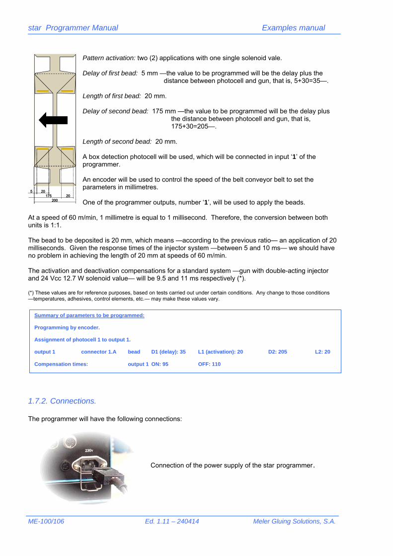
star Programmer Manual Examples manual
ME-100/106 Ed. 1.11 – 240414 Meler Gluing Solutions, S.A.
Pattern activation: two (2) applications with one single solenoid vale. Delay of first bead: 5 mm —the value to be programmed will be the delay plus the distance between photocell and gun, that is, 5+30=35—. Length of first bead: 20 mm. Delay of second bead: 175 mm —the value to be programmed will be the delay plus the distance between photocell and gun, that is, 175+30=205—. Length of second bead: 20 mm. A box detection photocell will be used, which will be connected in input ‘1’ of the programmer. An encoder will be used to control the speed of the belt conveyor belt to set the parameters in millimetres. One of the programmer outputs, number ‘1’, will be used to apply the beads.
At a speed of 60 m/min, 1 millimetre is equal to 1 millisecond. Therefore, the conversion between both units is 1:1. The bead to be deposited is 20 mm, which means —according to the previous ratio— an application of 20 milliseconds. Given the response times of the injector system —between 5 and 10 ms— we should have no problem in achieving the length of 20 mm at speeds of 60 m/min. The activation and deactivation compensations for a standard system —gun with double-acting injector and 24 Vcc 12.7 W solenoid value— will be 9.5 and 11 ms respectively (*). (*) These values are for reference purposes, based on tests carried out under certain conditions. Any change to those conditions —temperatures, adhesives, control elements, etc.— may make these values vary.
1.7.2. Connections. The programmer will have the following connections:
Connection of the power supply of the star programmer.
5 2020175
200
5 2020175
200
Summary of parameters to be programmed: Programming by encoder. Assignment of photocell 1 to output 1. output 1 connector 1.A bead D1 (delay): 35 L1 (activation): 20 D2: 205 L2: 20 Compensation times: output 1 ON: 95 OFF: 110

star Programmer Manual Examples manual
Meler Gluing Solutions, S.A. Vers. 1.11 - 240414 ME-101/106
Photocell and encoder connection.
Output connection for solenoid valve (1A)
1.7.3. Programming operating system. The parameters will be programmed in program 10. Turn the programmer on using the switch situated on the front panel. After the presentation screens, the password entry screen will appear Enter password —‘000’ by default—.
The first user level screen appears. From the main menu any of the twenty (20) possible programs that the star program has can be selected. To do so, press [1] and [ENTER], and the screen to enter the desired program will appear. By default the last program selected will flash on and off, e.g.: 1
To select the program of example ‘10’, press [1] [0] and [ENTER]. The screen will show the menu of the program selected. From the initial screen, after selecting the desired program, press [4] and [ENTER]. The photocell assignment screen will appear (T:Trigger) for each output channel (O: Output). In channels 1 (O1) we will make the selection for photocell ‘1’ Pulsar [ENTER] to confirm. Press [ESC] to return to the main menu. Press [5] and [ENTER]. The mode selection screen will appear. The mode between brackets is the mode currently selected Just press [ENTER] to change from one working mode to another. The selection of the example is ‘[Encoder]’.
Type password Password: 000_
1. Select program. 2. Utilities
Type program number ( 1 – 20 ) : 1
Program N. # 10 1. Pattern →
01 T:1 02 T:1 03 T:2 04 T:2 →
Control mode Time [Encoder] →
Control mode [Time] Encoder →
Program N. # 10 1. Pattern →
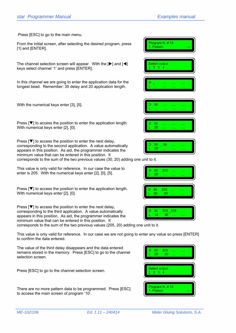
star Programmer Manual Examples manual
ME-102/106 Ed. 1.11 – 240414 Meler Gluing Solutions, S.A.
Press [ESC] to go to the main menu. From the initial screen, after selecting the desired program, press [1] and [ENTER]. The channel selection screen will appear. With the [] and [] keys select channel ‘1’ and press [ENTER]. In this channel we are going to enter the application data for the longest bead. Remember: 35 delay and 20 application length. With the numerical keys enter [3], [5]. Press [] to access the position to enter the application length. With numerical keys enter [2], [0]. Press [] to access the position to enter the next delay, corresponding to the second application. A value automatically appears in this position. As aid, the programmer indicates the minimum value that can be entered in this position. It corresponds to the sum of the two previous values (30, 20) adding one unit to it. This value is only valid for reference. In our case the value to enter is 205. With the numerical keys enter [2], [0], [5].
Press [] to access the position to enter the application length. With numerical keys enter [2], [0]. Press [] to access the position to enter the next delay, corresponding to the third application. A value automatically appears in this position. As aid, the programmer indicates the minimum value that can be entered in this position. It corresponds to the sum of the two previous values (205, 20) adding one unit to it. This value is only valid for reference. In our case we are not going to enter any value so press [ENTER] to confirm the data entered. The value of the third delay disappears and the data entered remains stored in the memory. Press [ESC] to go to the channel selection screen. Press [ESC] to go to the channel selection screen. There are no more pattern data to be programmed. Press [ESC] to access the main screen of program ‘10’.
Select output 1 2 3 4
D _ .... .... .... L .... .... .... ....
Program N. # 10 1. Pattern →
D 35 .... .... .... L 20 .... .... ....
D 35 _ 56 .... .... L 20 .... .... ....
D 35 .... .... .... L …. .... .... ....
Select output 1 2 3 4
Program N. # 10 1. Pattern →
D 30 205 .... .... L 20 20 .... ....
D 30 205 _226 .... L 12 20 .... ....
D 30 205 .... .... L 20 _…. .... ....
D 30 205 .... .... L 20 20 .... ....

star Programmer Manual Examples manual
Meler Gluing Solutions, S.A. Vers. 1.11 - 240414 ME-103/106
Press [6] and [ENTER]. The compensation values assignment screen will appear. Press [1] and [ENTER]. We have to enter the delay compensation values mentioned above, expressed in tenths of a millisecond (9.5 ms – 95). So, with the [] and[] keys go to the data to be modified —in this case ‘ON1’— and press [9], [5] and [ENTER] to memorise the value. Press [ESC], [2] and [ENTER] to access the deactivation data Remember: enter the delay values express in tenths of a millisecond (11 ms – 110). So, with the[ ] and[ ] keys go to the data to be modified —in this case ‘OFF1’— and press [1], [1], [0] and [ENTER] to memorise the value. Press [ESC] to access the main screen of program ‘10’. It is not necessary to program more data. We press [ESC] three (3) times to go to the initial access screen.
1.7.4. Encoder setting. The encode settings can be found in a restricted access menu (see chapter ‘3. Restricted level’ of the ‘Programming manual’). Enter —‘0000’ by default—. Access the main screen of this menu. Press [5] and [ENTER]. The encoder setting screen appears. We are going to set this parameter using method number 3 ‘produce size’. Press [3] and [ENTER]. With the machine running make two consecutive boxes pass under the photocell.
1. Activation 2. Deactivation
ON1: _150 ON2: 150 ON3: 150 ON4: 150
ON1: _ 95 ON2: 150 ON3: 150 ON4: 150
OFF1: _150 OFF2: 150 OFF3: 150 OFF4: 150
OFF1: _110 OFF2: 150 OFF3: 150 OFF4: 150
Program N. # 10 1. Pattern →
Type password Password: _
Type password Password: 0000_
Restricted menu 1.Change password →
Setting encoder 1.Set value →
Read impulses 000 impulses
Read impulses 500 impulses

star Programmer Manual Examples manual
ME-104/106 Ed. 1.11 – 240414 Meler Gluing Solutions, S.A.
!
!
Stop the machine immediately afterwards to have access to the box sizes later. Press [ENTER]. The pulses recorded between the start of one box and the start of the next are memorised and the following screen is displayed. The box measures 200 mm long and the distance between boxes is 50 mm. These values must be measured directly on the boxes that are used to measure the pulses.
The measurements must be as accurate as possible. The accuracy of the pulse/millimetre ratio depends on this and therefore the whole programme size control system.
Enter the measured value, [2], [5], [0] When you press [ENTER] the screen of the previous menu appears again. If we press [1] and [ENTER] we can display the resulting ratio (500:250 = 2).
This setting must be made in the encoder installation and it remains in use until the number of pulses of the encoder or the position of the encoder in the machine are changed.
Type size 000 mm
Type size 250 mm
Setting encoder 1. Set value →
Set value 02.00 impulses/mm

star Programmer Manual Examples manual
Meler Gluing Solutions, S.A. Vers. 1.11 - 240414 ME-105/106
2. Programming menu tree Some pages are included in the ‘Programming Manual’ (see ‘4. ’), which show all the screens of the star programmer and the access to each one them. It is useful to have these sheets at hand when carrying out new programmings or as reference to access data that we wish to modify.
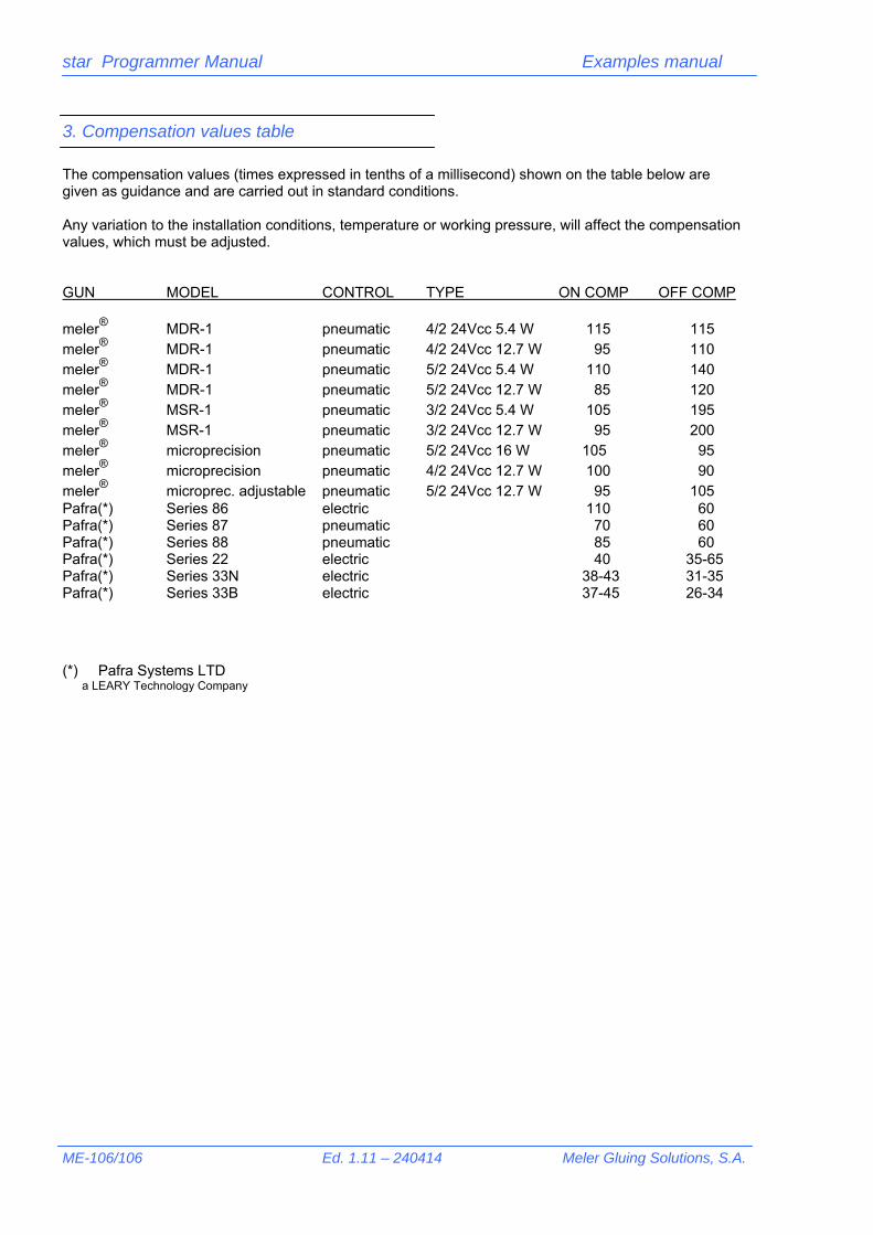
star Programmer Manual Examples manual
ME-106/106 Ed. 1.11 – 240414 Meler Gluing Solutions, S.A.
3. Compensation values table The compensation values (times expressed in tenths of a millisecond) shown on the table below are given as guidance and are carried out in standard conditions. Any variation to the installation conditions, temperature or working pressure, will affect the compensation values, which must be adjusted. GUN MODEL CONTROL TYPE ON COMP OFF COMP meler® MDR-1 pneumatic 4/2 24Vcc 5.4 W 115 115 meler® MDR-1 pneumatic 4/2 24Vcc 12.7 W 95 110 meler® MDR-1 pneumatic 5/2 24Vcc 5.4 W 110 140 meler® MDR-1 pneumatic 5/2 24Vcc 12.7 W 85 120 meler® MSR-1 pneumatic 3/2 24Vcc 5.4 W 105 195 meler® MSR-1 pneumatic 3/2 24Vcc 12.7 W 95 200 meler® microprecision pneumatic 5/2 24Vcc 16 W 105 95 meler® microprecision pneumatic 4/2 24Vcc 12.7 W 100 90 meler® microprec. adjustable pneumatic 5/2 24Vcc 12.7 W 95 105 Pafra(*) Series 86 electric 110 60 Pafra(*) Series 87 pneumatic 70 60 Pafra(*) Series 88 pneumatic 85 60 Pafra(*) Series 22 electric 40 35-65 Pafra(*) Series 33N electric 38-43 31-35 Pafra(*) Series 33B electric 37-45 26-34 (*) Pafra Systems LTD a LEARY Technology Company