Embed Size (px)
Citation preview
MINISTRY OF RAILWAYS (RAILWAY BOARD)MINISTRY OF RAILWAYS (RAILWAY BOARD)GOVERNMENT OF INDIA
DEVELOPMENT OF WORLD CLASS STATIONS THROUGH
PUBLIC PRIVATE PARTNERSHIP
MANUAL FOR STANDARDS AND SPECIFICATIONS FOR
RAILWAY STATIONS
June 2009

MINISTRY OF RAILWAYS (RAILWAY BOARD)MINISTRY OF RAILWAYS (RAILWAY BOARD)GOVERNMENT OF INDIA
DEVELOPMENT OF WORLD CLASS STATIONS THROUGH
PUBLIC PRIVATE PARTNERSHIP
MANUAL FOR STANDARDS AND SPECIFICATIONS FOR
RAILWAY STATIONS
June 2009
Volume one of twoVolume one of two
This is the technical document which has been produced by the Land & Amenities Directorate; Railway Board (Ministry of Railways). No deviation of these standards will take place without Board Permission In Board the final nodal authority is Advisor (Land &place without Board Permission. In Board, the final nodal authority is Advisor (Land & Amenities).
For any further technical clarifications and discrepancies, if any please contact:Advisor (L& A)Ministry of RailwaysRail BhawanNew Delhi 110001
Published by the Land & Amenities Directorate; Railway Board (Ministry of Railways).
Advisor (L& A)Ministry of RailwaysRail Bhawan New Delhi 110001
Printed by Bansal ElectrostatG-6 Siddhartha Building96 , Nehru placeN D lhi 110019New Delhi 110019
June 2009
Manual of Standards and Specifications for Railway Stations
i
Table of Contents
CONTENTS
(Volume 1 of 2) Foreword iv Preface v Acknowledgements vi List of Acronyms and Abbreviations vii List of Figures xi List of Tables xii SECTION 1.0 GENERAL, CODES AND CONDITIONS 1
SECTION 2.0 PLANNING AND DESIGN PRINCIPALS 16
SECTION 3.0 PLATFORM GEOMETRY AND SERVICES 27
SECTION 4.0 STATION DESIGN
4.1 INTRODUCTION 33
4.2 SAFETY & SECURITY 35
4.3 HANDICAP ACCESSIBILITY 49
4.4 MODULAR ELEMENTS APPROACH 54
4.5 STATION LAYOUT AND CIRCULATION
4.5.1 Introduction 58
4.5.2 Goals and Objectives 58
4.5.3 General Design Factors 60
4.5.4 Station Components 64
4.5.5 Parking and Vehicular Circulation 86
4.5.6 Concession and Commercial Areas 89
4.5.7 Sustainable Development Strategies 90
4.6 MATERIALS AND FINISHES 92
4.7 LIGHTING 102
4.8 ACOUSTICS 112
4.9 SIGNAGE AND GRAPHICS 120
4.10 ART AND ADVERTISING 128
4.11 FURNITURE, FIXTURE AND EQUIPMENT 133
Manual of Standards and Specifications for Railway Stations
ii
SECTION 5.0 STATION SERVICES
5.1. GENERAL 143
5.2. SUSTAINABLE DEVELOPMENT &
ENVIRONMENTAL CONSIDERATIONS 145
5.3. PARCEL STORAGE AND PARCEL MOVEMENT 157
5.4. SUPPORT SERVICE AREAS 160
5.5. UTILITY INTERFACE AND INFRASTRUCTURE SYSTEMS
5.5.1. Codes and Standards 172
5.5.2. Goals and Objectives 173
5.5.3. Utility Routing 173
5.5.4. Utility Adjacency Requirements 176
5.5.5. Electrical infrastructure 177
5.5.6. Plumbing and firefighting 189
5.5.7. Heating ventilation and air conditioning 200
SECTION 6.0 OPERATION AND MAINTENANCE 209
SECTION 7.0 CONSTRUCTION MANAGEMENT
7.1 GENERAL 218
7.2 USE OF THE SITE 219
7.3 STAGING PLAN 224
7.4 DIVERSION PLAN 226
7.5 SAFETY REQUIREMENTS DURING CONSTRUCTION 228
7.6 CONCESSIONAIRE’S LABOUR CAMP 240
7.7 CONCESSIONAIRE’S MANAGEMENT SYSTEM 241
7.8 SITE INSPECTIONS 252
7.9 SAFETY, HEALTH, AND ENVIRONMENTAL
PERSONNEL AND SERVICES 254
7.10 OPERATION AND MAINTENANCE (O&M) MANUALS 255
Indexing: - 256 Bibliography: - 260
Manual of Standards and Specifications for Railway Stations
iii
CONTENTS (Volume 2 of 2)
Foreword iv Preface v Acknowledgements vi List of Acronyms and Abbreviations vii List of Figures xi List of Tables xii List of annexure:- Number Section Title Page no. Annexure I 4.3 Relevant Extracts from ADA Accessibility
Guidelines for Buildings and Facilities (ADAAG) 262
Annexure II 4.9 Signage for Rail Users Ministry of Railways 289
Annexure III 4.9 International transportation graphic standard signs 359
Annexure IV 4.11 Telecom Directorate spec. RDSO/SPN/TC/67/2008
for True Colour Video-cum-Train Information Display
system 421
Annexure V 4.11 Telecom Directorate spec. RDSO/SPN/TC/62/2007
for digital clock with GPS Synchronization 470
Annexure VI 4.11 Telecom Directorate spec. RDSO/SPN/TC/76/2008
for Analog clock with GPS Synchronization 499
Annexure VII 4.11 Telecom Directorate spec RDSO/SPN/TC/65/2006
for Surveillance system 525
Annexure VIII 4.11 Telecom Directorate spec. RDSO/SPN/TC/63/2006
for Public Address system 561
Annexure IX 4.11 Telecom Directorate spec. RDSO/SPN/TC/61/2007
for Integrated Passenger Information system 585
Annexure X 5.4 Ticket Booth configurations as in western railways 658
Annexure XI 5.5 Extracts from Comprehensive Guidelines for
Passenger Amenities 662
Annexure XII 5.5 Relevant Extracts from Environment
(Protection) Act, 1986 671
Annexure XIII 7 Relevant Extracts from CFR 29 673
Indexing: - 256 Bibliography: - 260
Manual of Standards and Specifications for Railway Stations
iv
FOREWORD
In our endeavour to provide the best possible infrastructure for convenience and comfort of our passengers and other stakeholders, Indian railways have been improving the Railways Stations on a continuous basis. Towards this pursuit of excellence, L&A directorate has brought out this Manual of Standards and Specification for Railway Stations to be used for development of station into world class station through Public Private Partnership.
The first of its kind, this manual has laid down set of guidelines, standards and specifications for the construction of new Railway Stations or Redevelopment of the existing Stations to bring them up to the International Standards in terms of efficiency of operations and providing the comfort and convenience to our passengers and the stakeholders.
A number of stations of IR, located at metropolitan cities and important centers are identified for development through PPP route by leveraging a part of the real-estate development potential. Hon'ble Minister for Railways has already taken up an ambitious program of Redeveloping 26 station into world class station so far requiring huge investments. Most of these investments are expected to be realised through partnership with the private sector. Ensuring participation of the private sector in infrastructure development in a transparent manner requires specific framework. It requires a greater clarity on scope of work along with Expected performance parameters other than manageable level of risk and adequate service quality assurance at an affordable cost. This manual, I hope will serve this purpose by laying down the minimum standards that the MOR and the concessionaire will observe and expect on the matter of construction and management of these stations
I hope that this manual will be of interest to all those who are interested in redeveloping the station, either new or existing through PPP route into world class station. I wish all success to them in their endeavour to achieve a world class facility at Railway Stations.
June, 2009 Chairman, Railway Board

Manual of Standards and Specifications for Railway Stations
v
PREFACE
The objective of developing Manual of Standards and Specifications for Railway Stations is to
establish the bench marks for building either a new station or redevelop the existing Railway
Stations into world class stations through PPP route. Manual will provide norms and guidance to
future Station developers to build facilities comparable to International standards and yet remain
unique to the socioeconomic, cultural and other needs of the Indian Railways and its customers.
The Manual has been prepared with the intent to use it during the stage of development of master
plan and feasibility report and later as a part of the Concession Agreement for Railway Stations,
allowing the desired flexibility to the potential Concessionaires for innovation in design and
construction at reduced life cycle costs while improving efficiencies of operations,
performance, passenger comfort, and safety. By addressing a number of aspects of station
design without dictating design and operational processes, the Manual provides direction and clear
focus on issues and criteria that the Concessionaire needs to explore further in the design,
operational philosophies and performance standards for passenger safety, security, comfort and
desired levels of service. Manual also lays emphasis on modular, sustainable and
environmentally responsible construction management approach.
The Manual has been developed after extensive discussions and deliberations by team of
international experts and officials of Indian Railways. Committee of Executive Directors associated
with their Directors have gone through clause by clause of this manual and consider it as a living
document which shall be improved after every experience gained to provide specific guidance for
the redevelopment or construction of new Railway Stations to be taken next in hand in a manner
that shall achieve greater clarity and crypt-ness in the description.
I congratulate L&A directorate who have brought out this manual, the first of its kind with the help
of Superior global infrastructure Consulting Pvt. Ltd, other directorates of the Board, NR project
team and Rail Land Development Authority in such a short time and wish all success to those who
intends to use it.
June, 2009 Member/Engineering, Railway Board

Manual of Standards and Specifications for Railway Stations
vi
ACKNOWLEDGEMENT
Superior Global Infrastructure consulting (SGI) Pvt Ltd. express its heartfelt thanks to Ministry
Of Railways, Government of India for bestowing the confidence in SGI for developing Manual
for Standards and Specifications for Railways Stations to be used for development of stations
into World Class Station through Public Private Partnership. SGI expresses its gratitude for
the support and guidance of Shri Rakesh Chopra ME, Shri Satish Kumar Vij Ex-ME, other
members of the Railway Board, and the steering group namely Shri V.K.Gupta Advisor L&A
and other members of the group and their esteem colleague Shri R.P. Gupta Ex-VC, RLDA
and Advisor (works), Railway Board.
SGI would like to place on record the contribution of the member of Committee of Executive
Directors/Railway Board namely Shri P.K Aggarwal, ED L&A , Shri A.K Singh, ED ME(chg) ,
Shri Gopal Gupta IG (RPSF), Shri R.C Adwal ED (Tele), Smt Manju Gupta ED(EEM), RK
Tandon ED(PM) and Dr Pankaj Kapoor ED (Health Planning), whose guidance and feedback
had helped shaped this document.
SGI would like to express special thanks to Shri Anil K Lahoti CE/Const/NR, Shri S.K. Mishra
ED/T/PPP),Shri P.D Sharma Ex-ED/L&A & Menber, RLDA, Shri Anil Gupta GM RLDA and
Shri Rajesh Agarwal Director (World Class Station), Railway Board for their cooperation,
fruitful discussion and coordination, without whom this work would not have completed
June, 2009 President (SGI)

Manual of Standards and Specifications for Railway Stations
vii
LIST OF ACRONYMS AND ABBREVIATIONS AMASRA - Ancient Monuments and Archaeological Sites and Remains Act A&P - Access and Protection AAMA - American Architectural Manufacturers Association AASHTO - American Association of State Highway and Transportation Officials ACVVVF - AC variable voltage variable frequency ADA - Americans with Disability Act ADAAG - ADA Accessibility Guidelines AFC - Access Fare Collection ANSI - American National Standards Institute AOEG - Agent Operated Emergency Gates API - American Petroleum Industry APP - Accident Prevention Program APTA - American Public Transportation Association ARD - Automatic Rescue Device ASCE - American Society of Civil Engineers ASHRAE - American Society of Heating, Refrigerating and ASI - Archaeological Survey of India ASME - American Society of Mechanical Engineers ASTM - American Society for Testing and Materials ATM - Automatic Teller Machine BAS - Building Automated Systems BEE - Bureau of Energy Efficiency BIS - Bureau of Indian Standards BOCWA - Building and other construction workers Act BOCWR - Building and other construction workers Regulation BPC - Break Power Certificates BS - British Standard CA - Concession Agreement CBR - Collector Bus Room CBTC - Communications Based Train Control CCTV - Closed Circuit Tele Vision CEE - Chief Electrical Engineer CFC - Chloro Fluoro Carbons CFR - Code of Federal Regulations CIC - Customer Information Center CIS - Customer Information System CMU - Concrete Masonry Unit COF - Co efficient of Friction CPRI - Central Power Research Institute CRRI - Central Road Research Institute CU - Coefficient of Utilization CWR - Continuous Welded Rail DBFO - Design, Build, Finance, and Operate DOT - Department of Telecommunications DRM - Divisional Railway Manager ECS - Environmental Control System EDR - Electrical Distribution Rooms EIA - Environmental Impact Assessment
Manual of Standards and Specifications for Railway Stations
viii
EMI - Electro Magnetic Interference EMS - Environmental Management System EPA - Environmental Protection Agency (United States of America) EPR - Electrical Panel Room ERW - Energy Recovery Wheels ES - Electrical System EVACS - Emergency Voice Alarm Communication Systems F ACP - Fire Alarm Control Panel FAB - Fluidized Aerobic Bed FATU - Fresh Air Treatment Units FCC - Fire Command Centre FEC - Forward Error Correction FF&E - Furniture Fixtures and Equipments FOB - Foot Over Bridge FRLS - Fire Retardant Low Smoke GBC - Green Building Council (USA) GOI - Government of India GPS - Global Positioning System GRP - Government Railway Police HAZCOM - Hazard Communication HCP - Hazard Communication Program HPI - Help Point Intercom HVAC - Heating Ventilation Air Conditioning IAQ - Indoor Air Quality IATA - International Aviation Transportation Association IBC - International Building Code IDA - Indian Disability Act IDLH - Immediately Dangerous to Life & Health IE - Independent Engineer IEC - International Electrotechnical Commission IEEE - Institute of Electrical and Electronic Engineers IEQ - Indoor Environmental Quality IESNA - Illuminating Engineering Society of North America IIC - Interactive Inquiry Centers IOC - Indian Oil Corporation IPAS - Intelligent Parking Assist System IPIS - Integrated Passenger Information System IPT - Intermediate Public Transport IR - Indian Railways IRC - Indian Roads Congress IRWM - Indian Railway Works Manual ISA - International Symbol of Accessibility ISO - International Standards Organization Km - Kilometre(s) LT - Low voltage Transmission L&A - Land and Amenities LED - Light Emitting Diode LEED - Leadership in Energy and Environmental Design (USA) LLF - Light Loss Factor LOS - Level of Service
Manual of Standards and Specifications for Railway Stations
ix
LRT - Light Rail Transit MCA - Model Concession Agreement MEP - Mechanical, Electrical, Plumbing MOEF - Ministry of Environment and Forest, India MOR - Ministry of Railways MOR - Ministry of Railways, India MOSRTH - Ministry of Shipping, Road Transport & Highways MRTS - Mass Rapid Transit System MSDS - Material Safety Data Sheet NBC - National Building Code, India NEPA - National Environmental Policy Act NFPA - National Fire Protection Association O&M - Operations and Maintenance OHE - Over Head Electricals OHSAS - Occupational Health and Safety Advisory Services OSHA - Occupational Safety and Health Act OTE - Over Track Exhaust PA - Public Address PMIS - Project Management Information System PPE - Personal Protective Equipment PPP - Public Private Participation PTZ - Pan-Tilt-Zoom QAP - Quality Assurance Plan QAS - Quality Assurance System QM - Quality Manual QRA - Quantitative Risk Assessment RDSO - Research, Design, and Safety Organization RFID - Radio frequency identification RLDA - Rail Land Development Authority RMS - Rail Mail Service ROW - Right of Way RPF - Railway Protection Force RT - Reverberation Time SCADA - Supervisory Control & Data Acquisition System SEMP - Station Emergency management Panel SFPE - Society of Fire Protection Engineers SFPE - Society of Fire Protection Engineers SGI - Superior Global Infrastructure Consulting Pvt. Ltd. SHE - Safety, Health and Environment SIC - Station Information Centre SOP - Standing Operating Procedure SPCC Plan - Spill Prevention Control and Countermeasure Plan SPFE - Society of Fire Protection Engineers Sr. DME - Sr. Divisional Mechanical Engineer Sr. DOM - Sr. Divisional Operation Manager Sr. DSTE - Sr. Divisional Signal and Telecom Engineer SSA - Support Service Area SSC - Station Service Center SSM - Safety and Security Management S&T - Signal and Traction
Manual of Standards and Specifications for Railway Stations
x
STI - Speech Transmission Index STP - Sewage Treatment Plant SWP - Safe Work Plans TCPL - Toxicity Characteristic Leaching Procedure TCR - Train Control Room TDD - Telecommunications Display Device TERI - Tata Energy and Resource Institute TTE - Train Ticket Examiner TTY - Text Telephone TVM - Ticket Vending Machine UPE - Under Platform Exhaust UPS - Uninterrupted Power Supply UPVC - Unplasticised Poly Vinyl Chloride USEPA - United State Environmental Protection Agency UWLR - Upward Waste Light Ratio VCE - Vertical Circulation Elements VCT - Vinyl Composition Tile VMS - Variable Messaging System VOC - Volatile Organic Compounds WHO - World Health Organization XLPE - Cross-Linked Polyethylene
Manual of Standards and Specifications for Railway Stations
xi
List of Figures SECTION - 3 Fig. 1 of 3.2.1 : Centre Platform plan
Fig. 2 of 3.2.1 : Center platform section
Fig. 3 of 3.2.2 : Side platform plan and section
Fig. 4 of 3.2.3 : Split-level platform section
Fig. 5 of 3.2.3 : Stub terminal platform plan (e.g., Chattrapati Shivaji Terminus, Mumbai:
suburban platforms)
Fig. 6 of 3.2.3 : Flow-through platform plan
Fig. 7 of 3.2.3 : Flow-through platform section
Fig. 8 of 3.2.2 : Standard Dimensions for Tunnels & through Girder Bridges
Schedule I
Fig. 9 of 3.2.2 : Standard Dimensions for Tunnels & through Girder Bridges
to suit 25 K.V.A.C. Traction schedule I
Fig. 10 of 3.2.2 : Standard Dimensions out of Stations Schedule I
Fig. 11 of 3.2.2 : Standard Dimensions out of Stations to Suit 25 K.V.A.C. Traction schedule I Fig. 12 of 3.2.2 : Maximum Moving Dimensions
Fig. 13 of 3.2.2 : Standard Dimensions in Stations to Suit 25 K.V.A.C. Traction
Schedule I
Fig. 14 of 3.2.2 : Infringements of Schedule -I for 3660 mm Goods Stock &
New Standard Locomotives in Existing Tunnels Only
SECTION - 4
Fig. 1 of 4.2.3 : Security and Emergency Preparedness Planning Guide
Fig. 1 of 4.5.3 : Schematic diagram showing Passenger Circulation Flow within the Station
Fig. 1 of 4.5.4 : Typical station components
Fig. 2 of 4.5.4 : A cross section of the Elevator and the Landing Area
Fig. 1 of 4.8.3 : NR - Noise Rating Diagram
Fig. 1 of 4.8.3 : NR - Noise Rating Diagram
SECTION - 5
Fig. 1 of 5.5.6 : Water Balance Diagram
Fig. 1 of 5.5.6 : Figure Showing Process Flow of STP
Manual of Standards and Specifications for Railway Stations
xii
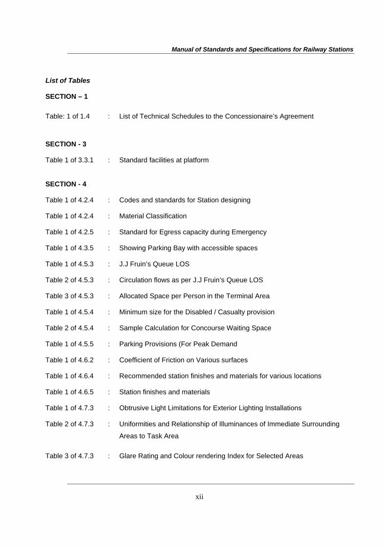
List of Tables SECTION – 1 Table: 1 of 1.4 : List of Technical Schedules to the Concessionaire’s Agreement
SECTION - 3
Table 1 of 3.3.1 : Standard facilities at platform
SECTION - 4
Table 1 of 4.2.4 : Codes and standards for Station designing
Table 1 of 4.2.4 : Material Classification
Table 1 of 4.2.5 : Standard for Egress capacity during Emergency
Table 1 of 4.3.5 : Showing Parking Bay with accessible spaces
Table 1 of 4.5.3 : J.J Fruin’s Queue LOS
Table 2 of 4.5.3 : Circulation flows as per J.J Fruin’s Queue LOS
Table 3 of 4.5.3 : Allocated Space per Person in the Terminal Area
Table 1 of 4.5.4 : Minimum size for the Disabled / Casualty provision
Table 2 of 4.5.4 : Sample Calculation for Concourse Waiting Space
Table 1 of 4.5.5 : Parking Provisions (For Peak Demand
Table 1 of 4.6.2 : Coefficient of Friction on Various surfaces
Table 1 of 4.6.4 : Recommended station finishes and materials for various locations
Table 1 of 4.6.5 : Station finishes and materials
Table 1 of 4.7.3 : Obtrusive Light Limitations for Exterior Lighting Installations
Table 2 of 4.7.3 : Uniformities and Relationship of Illuminances of Immediate Surrounding
Areas to Task Area
Table 3 of 4.7.3 : Glare Rating and Colour rendering Index for Selected Areas
Manual of Standards and Specifications for Railway Stations
xiii
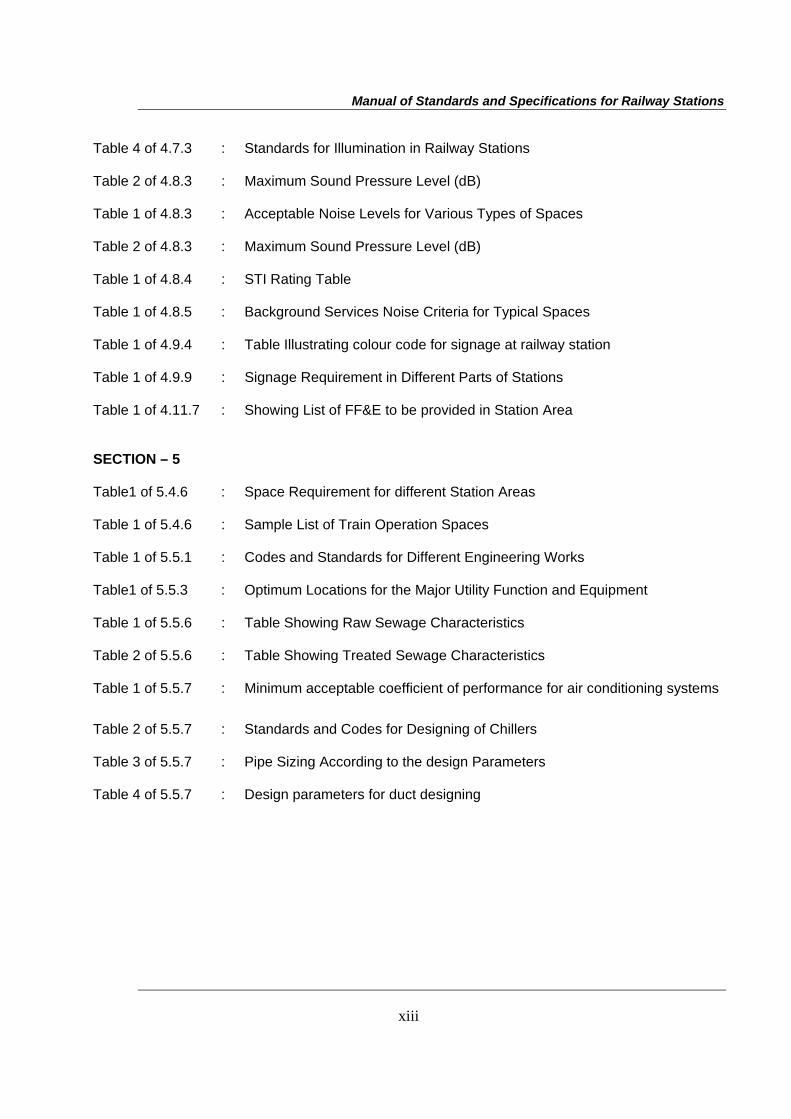
Table 4 of 4.7.3 : Standards for Illumination in Railway Stations
Table 2 of 4.8.3 : Maximum Sound Pressure Level (dB)
Table 1 of 4.8.3 : Acceptable Noise Levels for Various Types of Spaces
Table 2 of 4.8.3 : Maximum Sound Pressure Level (dB)
Table 1 of 4.8.4 : STI Rating Table
Table 1 of 4.8.5 : Background Services Noise Criteria for Typical Spaces
Table 1 of 4.9.4 : Table Illustrating colour code for signage at railway station
Table 1 of 4.9.9 : Signage Requirement in Different Parts of Stations
Table 1 of 4.11.7 : Showing List of FF&E to be provided in Station Area
SECTION – 5 Table1 of 5.4.6 : Space Requirement for different Station Areas
Table 1 of 5.4.6 : Sample List of Train Operation Spaces
Table 1 of 5.5.1 : Codes and Standards for Different Engineering Works
Table1 of 5.5.3 : Optimum Locations for the Major Utility Function and Equipment
Table 1 of 5.5.6 : Table Showing Raw Sewage Characteristics
Table 2 of 5.5.6 : Table Showing Treated Sewage Characteristics
Table 1 of 5.5.7 : Minimum acceptable coefficient of performance for air conditioning systems
Table 2 of 5.5.7 : Standards and Codes for Designing of Chillers
Table 3 of 5.5.7 : Pipe Sizing According to the design Parameters
Table 4 of 5.5.7 : Design parameters for duct designing
Manual of Standards and Specifications for Railway Stations
Section 1 General, Codes and Standards
1
Section 1
General, Codes and Standards
Manual of Standards and Specifications for Railway Stations
Section 1 General, Codes and Standards
2
1.0 GENERAL, CODES AND STANDARDS
1.1 Background 1.1.1 Indian Railways (IR) owns and manages one of the largest Railway networks of the
world with over 64,000 Route Kilometers (Km) and 7,000 stations. Operations of the Indian Railways (IR) are overseen by Ministry of Railways (MOR), Government of India and 16 Zonal Railways headed by General Managers. The IR carries more than 17.5 million passengers every day and some of the major Railway stations handle 100-200 million passengers per annum. Most of the Railway stations have been built over 100 years ago, and have a limited and aging infrastructure that handles an ever increasing number of passengers. The Railway stations are also located in the middle of the cities and offer enormous potential for re-development and commercial expansion. New passenger terminals are also being developed in cities where existing terminals cannot meet the future demand.
1.1.2 The MOR has decided to use world class standards to guide the redevelopment of the major stations in their system. These Projects are to be executed with Public Private Partnership (PPP) leveraging the real estate development potential in the air space above the station and on railway land around the station. Key objective of these projects are to provide superior services to railway passengers at the stations by converting them into urban icons and standard-bearers of the cities. The MOR is proposing the construction, maintenance and management of facilities at these stations to be done on the basis of Design, Build, Finance and Operate (DBFO) arrangement with successful bidders.
1.1.3 Prior to the procurement of the redevelopment team for each station, the MOR will issue this Manual for the Standards and Specifications for stations for Indian Railways. This would act as the guiding document for the planners and architects working on the redevelopment of specific stations. In addition consultants engaged to prepare master plans and feasibility studies for each station will also be provided with the manual for general guidance on the development of their plans and reports.
1.1.4 The Manual is intended to provide the station designer with a comprehensive set of standards for the design of stations. This Manual is intended to encourage the designer’s architectural vision, and focus on efficient movement of passengers with the convenience of transfers and interchanges with other modes of transportation, customer safety, security, comfort and convenience, while maintaining quality design (e.g., architectural quality, innovation, aesthetics, efficiency, and cost effectiveness), urban integration and preservation, and environmentally responsible design with use of materials and resources.
1.2 Scope
1.2.1 The scope of the work shall be as defined in the Concession Agreement (CA). Redevelopment of the project and operation and maintenance of areas and activities of the station earmarked shall be undertaken and completed by the Concessionaire as per the Specifications and Standards set forth in this Manual.
1.2.2 The Project railway station, surrounding traffic integration with the city and other modes of transport, and the passenger facilities shall conform to the design requirements set out in this Manual which are the minimum prescribed. The MOR will provide an architectural and urban master plan for the project station and the surrounding area on the project site which shall be followed by the Concessionaire in the project
Manual of Standards and Specifications for Railway Stations
Section 1 General, Codes and Standards
3
development. The MOR will also provide the feasibility report and other information for the project which shall be used by the Concessionaire only for its own reference and for carrying out its own design and investigations. The MOR is not liable for any inconsistency, inaccuracy, un-workability etc. in the feasibility report. The Concessionaire shall be solely responsible for undertaking all the necessary surveys, investigations, preliminary designs and detailed designs in respect of temporary and permanent works in accordance with the good industry practice and due diligence, and shall have no claim against the MOR for any loss, damage, risk, costs, liabilities or obligations arising out of or in relation to the feasibility report and other information provided by the MOR.
1.2.3 The feasibility report may include construction methodology and phased development plan for carrying out the station and railway yard redevelopment in a phased manner while the station is kept operational. The traffic block plan for carrying out the development works for the project shall be as specified in the CA. Alternative construction methodology and phased development plan may be adopted by the Concessionaire in accordance with design requirements set out in this Manual and within the traffic block plan set out in the CA and three copies of each shall be sent to the Independent Engineer (the “IE”) for review and comments, if any. The IE’s comments shall specify the conformity, or otherwise, of such designs and Specifications with the requirements specified in the Manual.
1.3 Management System
Concessionaire shall establish a quality management system of international best practices that to a minimum be conforming to the International Standards Organization (ISO) 14001 during construction, ISO 18001 during operation and maintenance of station facilities and ISO 9001 for other stages during the Concession Period. At least two weeks prior to commencement of the work, the Concessionaire shall draw up a Quality Assurance Manual (QAM) covering the Quality System (QS), Quality Assurance Plan (QAP) and documentation for all aspects of the design, construction and maintenance of the Project complying with the requirements of sections 7.7.1, 7.7.2, and 7.7.4 and send three copies of each to the IE for review. The class of quality assurance shall not be less than Q-3.
1.4 Guidelines for Preparing Schedules of the Concession Agreement
Certain paragraphs (full or part) in Sections 1 to 7 of this Manual refer to the Schedules of the Concession Agreement (CA). Following is a preliminary list of schedules that may be included in the final Concessionaire’s Agreement. While finalizing the feasibility report for the project station, and the scope of the project, each of these paragraphs should be carefully examined. MOR at its discretion may make some or all of these schedules and their respective annexure part of the CA.
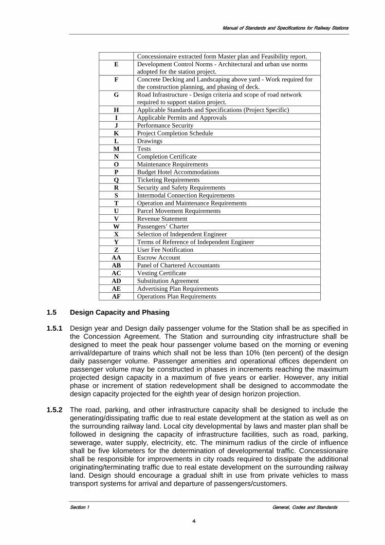
Table: 1 of 1.4 List of Technical Schedules to the Concessionaire’s Agreement
Schedule Title/Description A Site of Project - Details of site of project, relationship to context and
surroundings, land transfer issues, present and permitted land uses B Relocation of Facilities - Detail of existing railway structures that
require relocation, alternate sites, schedules and temporary relocations.
C Redevelopment of Railway Yard - Work required in rail yard and associated operational facilities, phasing, CRS sanctions, and commissioning.
D Facilities at Station terminal - Minimum facilities to be provided by
Manual of Standards and Specifications for Railway Stations
Section 1 General, Codes and Standards
4
Concessionaire extracted form Master plan and Feasibility report. E Development Control Norms - Architectural and urban use norms
adopted for the station project. F Concrete Decking and Landscaping above yard - Work required for
the construction planning, and phasing of deck. G Road Infrastructure - Design criteria and scope of road network
required to support station project. H Applicable Standards and Specifications (Project Specific) I Applicable Permits and Approvals J Performance Security K Project Completion Schedule L Drawings M Tests N Completion Certificate O Maintenance Requirements P Budget Hotel Accommodations Q Ticketing Requirements R Security and Safety Requirements S Intermodal Connection Requirements T Operation and Maintenance Requirements U Parcel Movement Requirements V Revenue Statement W Passengers’ Charter X Selection of Independent Engineer Y Terms of Reference of Independent Engineer Z User Fee Notification
AA Escrow Account AB Panel of Chartered Accountants AC Vesting Certificate AD Substitution Agreement AE Advertising Plan Requirements AF Operations Plan Requirements
1.5 Design Capacity and Phasing
1.5.1 Design year and Design daily passenger volume for the Station shall be as specified in the Concession Agreement. The Station and surrounding city infrastructure shall be designed to meet the peak hour passenger volume based on the morning or evening arrival/departure of trains which shall not be less than 10% (ten percent) of the design daily passenger volume. Passenger amenities and operational offices dependent on passenger volume may be constructed in phases in increments reaching the maximum projected design capacity in a maximum of five years or earlier. However, any initial phase or increment of station redevelopment shall be designed to accommodate the design capacity projected for the eighth year of design horizon projection.
1.5.2 The road, parking, and other infrastructure capacity shall be designed to include the generating/dissipating traffic due to real estate development at the station as well as on the surrounding railway land. Local city developmental by laws and master plan shall be followed in designing the capacity of infrastructure facilities, such as road, parking, sewerage, water supply, electricity, etc. The minimum radius of the circle of influence shall be five kilometers for the determination of developmental traffic. Concessionaire shall be responsible for improvements in city roads required to dissipate the additional originating/terminating traffic due to real estate development on the surrounding railway land. Design should encourage a gradual shift in use from private vehicles to mass transport systems for arrival and departure of passengers/customers.
Manual of Standards and Specifications for Railway Stations
Section 1 General, Codes and Standards
5
1.5.3 Real estate development at the station has to be constructed along with the station. However, real estate development on the surrounding railway land may be constructed in phases at the discretion of Concessionaire.
1.6 Environment, Health and Safety Plans
Before taking up any construction or maintenance operations for the project station and the surrounding project railway land the Concessionaire shall first prepare safety, health and environmental plans complying with the requirements specified in sections 7.4, 7.5, 7.6, 7.7.3, 7.7.5, and 7.7.6 to ensure the safety to trains, passengers, road traffic, construction workers, pedestrians and people living in the neighborhood. The Concessionaire send three copies of each to the Independent Engineer for review and comments, before taking up the construction or maintenance work.
1.7 Review and comments by Independent Engineer
In cases where the Concessionaire is required to send any drawings or documents to the Independent Engineer for review and comments, and in the event such comments are received by the Concessionaire, it shall duly consider such comments in accordance with the Concession Agreement and Good Industry Practice for taking appropriate action thereon.
1.8 Definition and Interpretation
1.8.1 All the obligations of the Concessionaire arising out of the provisions of this Manual shall be subject to, and shall conform to the provisions of the Concession Agreement. See section 2.4.4 for order of precedence of governing documents.
1.8.2 The definitions contained in the Concession Agreement for Public Private Partnership in Railway Stations executed for a station shall apply to the provisions of this Manual. Terms or words not defined herein shall be governed by the definitions contained in the IR standards and manuals specified under section 1.11.
1.9 Design Life and Serviceability
1.9.1 Design life of a structure is that period for which it is designed to fulfill its intended function when inspected and maintained in accordance with agreed procedures. The assumption of a design life for a structure or component does not mean that the structure will no longer be fit for its purpose at the end of that period. Neither will it necessarily continue to be serviceable for that length of time without adequate and regular inspection and routine maintenance. Design life and serviceability requirements for the various elements of the structures used in the Project shall be as provided hereunder.
1.9.2 Civil Engineering Structures
The design life of all major civil engineering structures, such as platforms, concourse, other parts of Station building, viaducts, bridges, underground works, multi storey buildings, etc. shall be a minimum of 120 years unless otherwise specified in this Manual or the Concession Agreement.
1.9.3 The design life of washable apron (ballastless track bed) and all building structures up to two stories shall be a minimum of 50 years unless otherwise specified in this Manual or the Concession Agreement.
Manual of Standards and Specifications for Railway Stations
Section 1 General, Codes and Standards
6
1.9.4 The design life of pavements shall conform to code provisions however; it shall be not less than 15 years for bituminous pavements and 25 years for concrete pavements.
1.10 Codes and Standards Application
1.10.1 This Manual forms part of the basis of design, construction and operation of the Project Railway Station in conjunction with other codes, standards, as specified hereunder. In addition to these manuals, standards and specifications, the project specific requirements laid down in the Master Plan and Feasibility Report for the station forming part of the Concession Agreement, rulings by regulatory agencies having jurisdiction, requirements of the local authorities, project-specific objectives and functional requirements dictated by site, or other project-specific constraints comprise the overall requirements for the development of any Project Station. Applicable codes, standards, and regulations (legal and regulatory requirements) shall be threshold requirements for the basis of the station design. Conformance and compliance with these regulatory requirements is the first measure of minimum station design adequacy and performance of the project.
1.10.2 Indian Railways Standards, Manuals and Specifications as per Clause 1.11 shall be applicable to the Project. Any other standard, manual or specification referred to in the Manual and any supplement issued with the bid document shall also be applicable to the Project.
1.10.3 Latest version of the Codes, Standards, specifications, etc. notified/published at least 60 days before the last date of bid submission shall be considered applicable for the initial redevelopment of the station. However, any subsequent revision of such codes, standards and specifications, etc. with respect of operation and maintenance of areas and activities shall be complied with, by the Concessionaire within 5 years of the bid submission.
1.10.4 The Concessionaire shall submit its proposal to the IE for review before carrying out the compliance of any such revision as described in 1.10.3. The terms ‘Ministry of Railways’ and ‘Railway Board’ or any successor or substitute thereof mentioned in these codes, standards, manuals and specifications shall be considered as synonymous. In case of any conflict or inconsistency with the provisions of the applicable IR Standards, Manuals and Specifications, the provisions contained in this Manual and the Specifications and Standards specified in this Manual shall apply.
1.10.5 In the absence of any specific provision on any particular issue in the aforesaid Codes or Specifications read in conjunction with the Specifications and Standards contained in this Manual, the following Standards shall apply in order of priority except in case of fire system for station where NFPA has over riding priority:
(i) National Building Code (Except in case of fire system for station building where NFPA has overriding priority over NBC)
(ii) Bureau of Indian Standards
(iii) American Standards, such as NFPA, ASTM, AASHTO (American Association of State Highway and Transportation Officials), British Standards, International standards.
(iv) Any other specifications/standards proposed by the Concessionaire and review and concurred by the IE.
Manual of Standards and Specifications for Railway Stations
Section 1 General, Codes and Standards
7
1.10.6 All items of track, signaling and over head equipment works shall conform to the Indian Railways Standards, Manuals and Research, Design, and Standards Organization (RDSO) Specifications. All items of road works shall conform to Indian Roads Congress (IRC) Codes and Standards Specifications for Road and Bridge Works, Ministry of Shipping, Road Transport & Highways (MOSRTH) Specifications. New technology used in this area that is not currently available in India shall conform to appropriate International standards.
1.10.7 Alternative Standards and Specifications
The requirements stated in the Manual for the design of the Project Station are the minimum. The Concessionaire will, however, be free to adopt international practices, alternative specifications, materials and standards to bring in innovation in the design and construction provided they are comparable to or better than the standards prescribed in the Manual. Such a proposal shall be submitted by the Concessionaire to the Independent Engineer for review, comments if any and concurrence. In case, the Independent Engineer is of the opinion that the proposal submitted by the Concessionaire is not in conformity with any of the international standards or codes, then he will record his reasons and convey the same to the Concessionaire for compliance. A record shall be kept by the Independent Engineer, of the non-compliance by the Concessionaire of the minimum Specifications and Standards specified in the Manual and shall be dealt with in terms of the provisions of the Concession Agreement. The Concessionaire shall be responsible for adverse consequences, if any, arising from any such non-compliance.
If the alternate standards affect track, S&T or other railway related electrical installations the Concessionaire must also through the IE obtain the formal approval for the alternate standard from MOR.
1.10.8 Statutory Approvals for Electrification Work
For any work that directly affects or is directly affected by the electrification of the railway lines the following requirements will apply. Chief Electrical Engineer (CEE)-Zonal Railway CEE is the Administrative Head of the Electrical Department, with overall responsibility for efficient working of the department. He is responsible to the General Manager in all matters pertaining to Electric Traction and Electrical General Services. On behalf of the General Manager, he directs and supervises all electrical works related to Railway, whether executed by Divisional Officer or by independent Organization. CEE also functions as Electrical Inspector to the Government as defined in Section 162(1) of Indian Electricity Act-2003, in respect of all high voltage electrical installations and equipment owned by the Railways. This includes all high voltage electrical installations in the Railway including transmission lines, 25 KV feeder lines, sub-stations, switching stations which although running outside Railway premises, are, nevertheless, owned by the Railway. He is responsible for administration of the Electricity Rules in the Railway. In regard to electric traction installations, in his capacity as Electrical Inspector, CEE is chiefly responsible for the following: • Scrutiny and approval of the layout and designs for sub-stations, OHE and other
installations for compliance with the Indian Electricity Act and Rules; • Inspection of the completed installations, either personally or by deputing his
officers, for compliance with the safety requirements; • Approval for energizing of the installations;
Manual of Standards and Specifications for Railway Stations
Section 1 General, Codes and Standards
8
• Statutory inspection of the installations periodically under Rule 46 of the Indian Electricity Rules;
• Investigation of Electrical accidents and Issuing directives to prevent their recurrence; and
• Submission of annual report to Central Electricity Authority
1.11 List of Codes and Standards
An indicative list of Indian and International Laws, Codes, Standards, and Specifications is given below for reference. Actual application of the following codes and standards will be defined in the respective sections of the manual.
Design 1. National Building Code (India) 2. Ancient Monuments Preservation Act (India) 3. Ancient Monuments and Archaeological Sites and Remains Act, 1958 4. India Disability Act 5. Earthquake Code (India) 6. The Energy and Resource Institute (India) 7. The Indian Electricity Rules, 1956 and The Indian Electricity Act, 2003 8. Indian Electricity Rule 1956 9. Delhi Fire Prevention and Safety Act 1986 10. Inflammable Substances Act 1962 11. Delhi Tree Preservation Act (1994) 12. Guidelines and Space Standards for Barrier Free Built Environment for Disabled
and Elderly Persons, 1998, Centre Public Works Department (CPWD), Ministry of Urban Affairs and Employment, (India)
13. Indian Standard Hand Book on steel sections Part-I 14. Indian Railway Manual on Design and Construction of well and pile foundations 15. Green Building Council (GBC), (USA) 16. Leadership in Energy and Environmental Design (LEED), USA. 17. NFPA 10 – Fire extinguishers (USA) 18. NFPA 14 – Sprinklers (USA) 19. NFPA 30 – Combustible materials (USA) 20. NFPA 70 – Electrical Installations (USA) 21. NFPA 72 – Alarm and sprinklers (USA) 22. NFPA 90 – Station work shops (USA) 23. NFPA 91 – Ventilation (USA) 24. NFPA 101 – Life Safety Code (USA) 25. NFPA 110 – Emergency back up power (USA) 26. NFPA 130 – Standard for Fixed Guideway Transit and Passenger Rail Systems
(USA) 27. NFPA 220 – Construction Materials (USA) 28. NFPA 251– Ancillary spaces (USA) 29. American with Disability Act (ADA) of 1990 30. Accessibility Guidelines for Buildings and Facilities (ADA Accessibility Guidelines,
ADAAG), 1998 (USA) 31. ASHRAE Handbook Fundamentals (USA) 32. ASHRAE 62.1 – Ventilation (USA) 33. ASHRAE 149-2000 – Ventilation (USA) 34. International Building Code (IBC) 35. ASME – A 17.1, Safety Code for Elevators and Escalators (USA)
Manual of Standards and Specifications for Railway Stations
Section 1 General, Codes and Standards
9
36. IIEC (International Electrotechnical Commission) 60849:1998, Sound Systems for Emergency Purposes (USA)
37. American Petroleum Industry (API) Standard 1104 Underground Storage Tank 38. ISO 9001, International Standards Organization, Standard for Quality
Construction
39. Building and other Construction Workers’ Welfare Cess Act, 1996 and Central Rules, 1998 (India)
40. The Workmen’s Compensation Act, 1923 along with Allied Rules (India) 41. The Payment of Wages Act, 1936 (India) 42. The Minimum Wages Act, 1948 and Rules 1950 (India) 43. Contract Labour Act, 1970 and Rules 1971 (India) 44. Child Labour (Prohibitions and Regulations) Act, 1986 and Rules 1950 (India) 45. Fly Ash Utilization Notification, Sept 1999 as amended in August 2003 (India) 46. Notification, Central Ground Water Board, Act January 1997 47. OSHA (Occupational Safety and Health Administration) Safety and Health
Regulations in Construction (USA) 48. OSHA 18001-1999 – Occupational Health and Safety Management System (USA) Environmental, Health and Safety 49. Food Safety and Standards 2006 50. The Factories Act (India) 51. Motor Vehicle Act as amended in 1994 and the Central Motor Vehicle Rules, 1989
(India) 52. The Petroleum Act, 1934 and Rules, 1976 (India) 53. Gas Cylinder Rules, 2003 (India) 54. Indian Explosives Act, 1884, along with the Explosives Substance Act 1998 and
the Explosives Rules 1983 55. The (Indian) Boilers Act, 1923 56. The Public Liability Insurance Act, 1991 and Rules 1991 (India) 57. The Mines Act, 1952 (India) 58. Environment Protection Act, 1986 and Rules 1986 (India) 59. Air (Prevention and Control of Pollution) Act, 1981 (India) 60. Water (Prevention and Control of Pollution) Act, 1974 (India) 61. The Noise Pollution (Regulation and Control) Rules, 2000 (India) 62. Notification on Control of Noise from Diesel Generator (DG) sets, 2002 (India) 63. Energy Conservation Building Code (India), 2007 64. Recycled Plastic Usage Rules, 1998 65. Manufacture, Storage, and Import of Hazardous Chemicals Rules, 1989 66. The Hazardous Waste (Management and Handling) Rules, 1989 67. Batteries (Management and Handling) Rules 68. E-Waste Manual 2005 69. Municipal Solid Waste Management rules 2001 70. Bio Medical Waste rules 2001 71. Water (prevention and Control of Pollution) Cess Act 1977 and rules 1978 72. United States Environmental Protection Agency (USEPA) Rules and Regulations
as outlined in Title 40, Code of Federal Regulations (CFR) – Protection of the Environment.
73. SFPE (Society of Fire Protection Engineers) Handbook (USA) 74. Occupational Health and Safety Advisory Services (OHSAS) 75. Handbook for Transit Safety and Security Certification USTA (USA) 76. IEEE (Institute of Electrical and Electronic Engineers) (USA)
Manual of Standards and Specifications for Railway Stations
Section 1 General, Codes and Standards
10
77. Transportation Risk Assessment of transportation premises and facilities (UK) 78. ISO 14001, International Standards Organization, Standard for Environmental
Management System
Indian Railways Manuals and Standards 79. Indian Railways Works Manual, 2000 80. Indian Railways Permanent Way Manual 81. Indian Railways Telecom Manual 2007 82. Indian Railways Coaching Maintenance Manual 83. Indian Railway Medical Manual 84. Manual for Fusion welding of Rail by the Alumino-thermic Process 85. Manual for Flash Butt Welding of Rails 86. Manual of glued insulated rail joints 87. Indian Railways Manual of AC Traction Maintenance and Operation, Volume – I 88. Indian Railways Manual of AC Traction Maintenance and Operation, Volume – II
(Part I) 89. Indian Railways Manual of AC Traction Maintenance and Operation, Volume – II
(Part II) 90. Indian Railways Manual of AC Traction Maintenance and Operation, Volume – III 91. Signal Engineering Manual, Part I 92. Signal Engineering Manual, Part II 93. Indian Railways Schedule of Dimensions 1676mm Gauge (BG), Revised 2004 94. All Pertinent IRS Specifications issued by the various Directorates of the Ministry
of Railways (e.g., Signal Directorate, Bridges and Structures Directorate, Track Directorate, Telecom Directorate, Traction Installation Directorate, Electrical Directorate, etc.)
95. IRS Bridge Rules for Loading 96. IRS Code of Practice for Steel Bridges 97. IRS Code of Practice for Plain, Reinforced and Pre-stressed Concrete for general
Bridge Construction 98. IRS Code of Practice for the Design of Substructures and Foundation of Bridges
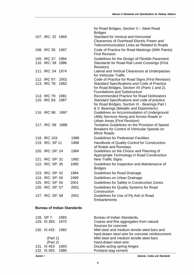
Indian Roads Congress (IRC) Standards
99. IRC 5: 1985 Standard Specifications and Code of Practice for Road Bridges, Section I -General Features of Design
100. IRC 6: 1966 Standard Specifications and Code of Practice for Road Bridges, Section II – Loads and Stresses
101. IRC 11: 1962 Recommended practice for the design of lay out of cycle tracks
102. IRC 18: 1985 Design Criteria for Prestressed Concrete Road Bridges (Post-Tensioned Concrete)
103. IRC 19: 1977 Standard Specifications and code of Practice for Water Bound Macadam
104. IRC 21: 1987 Standard Specifications and Code of Practice for Road Bridges Section III–Cement Concrete (Plain and Reinforced)
105. IRC 22: 1986 Standard Specifications and Code of Practice for Road Bridges, Section VI – Composite Construction
106. IRC 24: 1967 Standard Specifications and Code of practice
Manual of Standards and Specifications for Railway Stations
Section 1 General, Codes and Standards
11
for Road Bridges, Section V – Steel Road Bridges
107. IRC: 32 1969 Standard for Vertical and Horizontal Clearances of Overhead Electric Power and Telecommunication Lines as Related to Roads
108. IRC 35: 1997 Code of Practice for Road Markings (With Paints) First Revision
109. IRC 37: 1984 Guidelines for the Design of Flexible Pavement 110. IRC: 39 1986 Standards for Road-Rail Level Crossings (First
Revision) 111. IRC: 54 1974 Lateral and Vertical Clearances at Underpasses
for Vehicular Traffic 112. IRC 67: 2001 Code of Practice for Road Signs (First Revision) 113. IRC 78: 1983 Standard Specifications and Code of Practice
for Road Bridges, Section VII (Parts 1 and 2), Foundations and Substructure
114. IRC 79: 1981 Recommended Practice for Road Delineators 115. IRC 83: 1987 Standard Specifications and code of practice
for Road Bridges, Section IX - Bearings Part I & II: Bearings (Metallic and Elastomeric)
116. IRC 98: 1997 Guidelines on Accommodation of Underground Utility Services Along and Across Roads in Urban Areas (First Revision)
117. IRC: 99 1988 Tentative Guidelines on the Provision of Speed Breakers for Control of Vehicular Speeds on Minor Roads
118. IRC 103: 1988 Guidelines for Pedestrian Facilities 119. IRC: SP 11 1988 Handbook of Quality Control for Construction
of Roads and Runways 120. IRC: SP: 24 1984 Guidelines on the Choice and Planning of
Appropriate Technology in Road Construction 121. IRC: SP: 31 1992 New Traffic Signs 122. IRC: SP: 35 1990 Guidelines for Inspection and Maintenance of
Bridges 123. IRC: SP: 42 1994 Guidelines for Road Drainage 124. IRC: SP: 50 1999 Guidelines on Urban Drainage 125. IRC: SP: 55 2001 Guidelines for Safety in Construction Zones 126. IRC: SP: 57 2001 Guidelines for Quality Systems for Road
Construction 127. IRC: SP: 58 2001 Guidelines for Use of Fly Ash in Road
Embankments
Bureau of Indian Standards
128. SP 7: 1983 Bureau of Indian Standards. 129. IS 383: 1970 Coarse and fine aggregates from natural
Sources for concrete 130. IS 432: 1982 Mild steel and medium tensile steel bars and
hard-drawn steel wire for concrete reinforcement (Part 1) Mild steel and medium tensile steel bars (Part 2) Hard-drawn steel wire
131. IS 453: 1993 Double-acting spring hinges 132. IS 455: 1989 Portland slag cement
Manual of Standards and Specifications for Railway Stations
Section 1 General, Codes and Standards
12
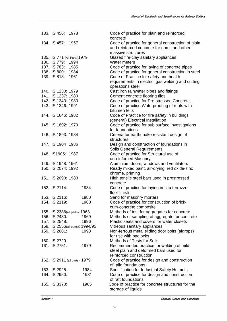
133. IS 456: 1978 Code of practice for plain and reinforced concrete
134. IS 457: 1957 Code of practice for general construction of plain and reinforced concrete for dams and other massive structures
135. IS 771 (All Parts)1979 Glazed fire-clay sanitary appliances 136. IS 779: 1994 Water meters 137. IS 783: 1985 Code of practice for laying of concrete pipes 138. IS 800: 1984 Code of practice for general construction in steel 139. IS 818: 1961 Code of Practice for safety and health
requirements in electric, gas welding and cutting operations steel
140. IS 1230: 1979 Cast iron rainwater pipes and fittings 141. IS 1237: 1980 Cement concrete flooring tiles 142. IS 1343: 1980 Code of practice for Pre-stressed Concrete 143. IS 1346: 1991 Code of practice Waterproofing of roofs with
bitumen felts 144. IS 1646: 1982 Code of Practice for fire safety in buildings
(general) Electrical Installation 145. IS 1892: 1979 Code of practice for sub surface investigations
for foundations 146. IS 1893: 1984 Criteria for earthquake resistant design of
structures 147. IS 1904 1986 Design and construction of foundations in
Soils General Requirements 148. IS1905: 1987 Code of practice for Structural use of
unreinforced Masonry 149. IS 1948: 1961 Aluminium doors, windows and ventilators 150. IS 2074: 1992 Ready mixed paint, air-drying, red oxide-zinc
chrome, priming 151. IS 2090: 1983 High tensile steel bars used in prestressed
concrete 152. IS 2114: 1984 Code of practice for laying in-situ terrazzo
floor finish 153. IS 2116: 1980 Sand for masonry mortars 154. IS 2119: 1980 Code of practice for construction of brick-
cum-concrete composite 155. IS 2386(all parts): 1963 Methods of test for aggregates for concrete 156. IS 2430: 1969 Methods of sampling of aggregate for concrete 157. IS 2548: 1996 Plastic seats and covers for water closets 158. IS 2556(all parts): 1994/95 Vitreous sanitary appliances 159. IS 2681: 1993 Non-ferrous metal sliding door bolts (aldrops)
for use with padlocks 160. IS 2720 Methods of Tests for Soils 161. IS 2751: 1979 Recommended practice for welding of mild
steel plain and deformed bars used for reinforced construction
162. IS 2911 (all parts): 1979 Code of practice for design and construction of pile foundations
163. IS 2925 : 1984 Specification for Industrial Safety Helmets 164. IS 2950: 1981 Code of practice for design and construction
of raft foundations 165. IS 3370: 1965 Code of practice for concrete structures for the
storage of liquids
Manual of Standards and Specifications for Railway Stations
Section 1 General, Codes and Standards
13
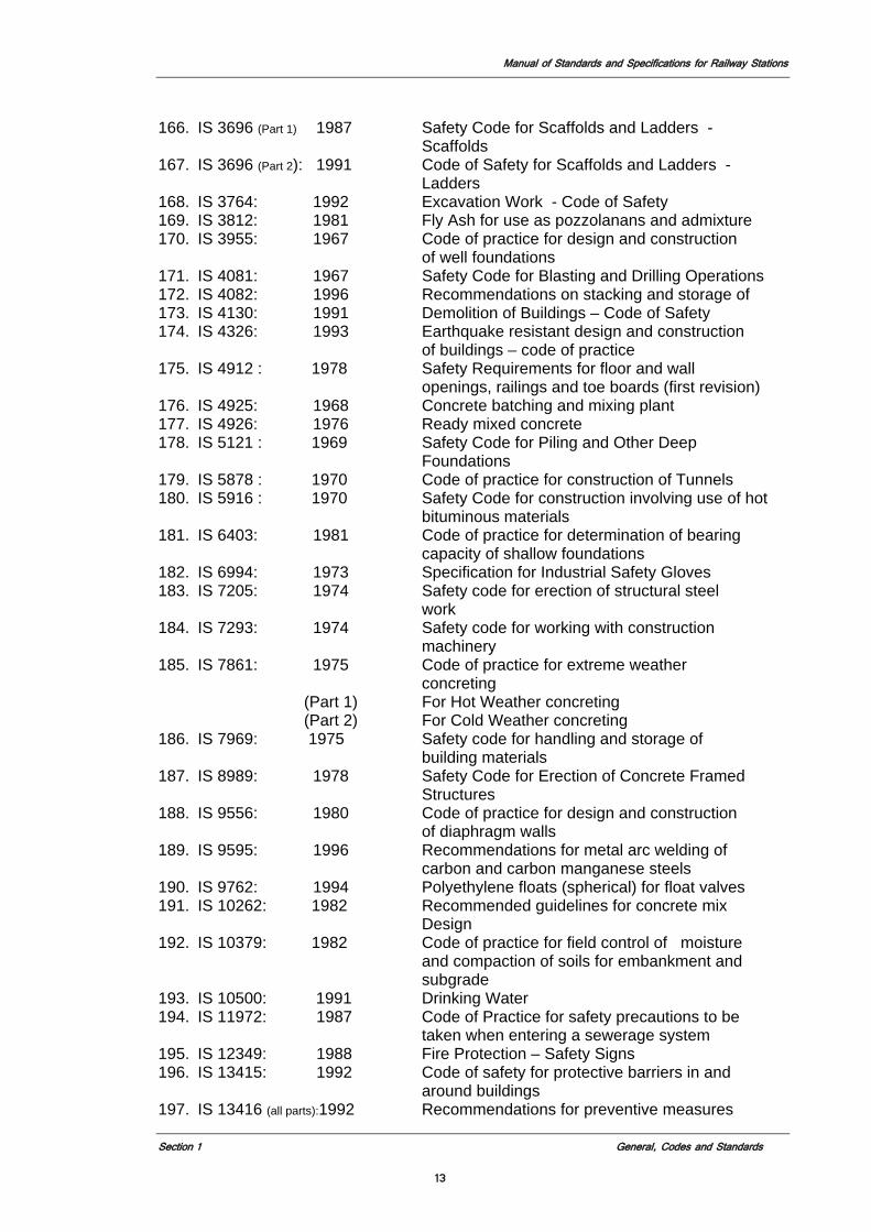
166. IS 3696 (Part 1) 1987 Safety Code for Scaffolds and Ladders - Scaffolds
167. IS 3696 (Part 2): 1991 Code of Safety for Scaffolds and Ladders - Ladders
168. IS 3764: 1992 Excavation Work - Code of Safety 169. IS 3812: 1981 Fly Ash for use as pozzolanans and admixture 170. IS 3955: 1967 Code of practice for design and construction
of well foundations 171. IS 4081: 1967 Safety Code for Blasting and Drilling Operations 172. IS 4082: 1996 Recommendations on stacking and storage of 173. IS 4130: 1991 Demolition of Buildings – Code of Safety 174. IS 4326: 1993 Earthquake resistant design and construction
of buildings – code of practice 175. IS 4912 : 1978 Safety Requirements for floor and wall
openings, railings and toe boards (first revision) 176. IS 4925: 1968 Concrete batching and mixing plant 177. IS 4926: 1976 Ready mixed concrete 178. IS 5121 : 1969 Safety Code for Piling and Other Deep
Foundations 179. IS 5878 : 1970 Code of practice for construction of Tunnels 180. IS 5916 : 1970 Safety Code for construction involving use of hot
bituminous materials 181. IS 6403: 1981 Code of practice for determination of bearing
capacity of shallow foundations 182. IS 6994: 1973 Specification for Industrial Safety Gloves 183. IS 7205: 1974 Safety code for erection of structural steel
work 184. IS 7293: 1974 Safety code for working with construction
machinery 185. IS 7861: 1975 Code of practice for extreme weather
concreting (Part 1) For Hot Weather concreting (Part 2) For Cold Weather concreting 186. IS 7969: 1975 Safety code for handling and storage of
building materials 187. IS 8989: 1978 Safety Code for Erection of Concrete Framed
Structures 188. IS 9556: 1980 Code of practice for design and construction
of diaphragm walls 189. IS 9595: 1996 Recommendations for metal arc welding of
carbon and carbon manganese steels 190. IS 9762: 1994 Polyethylene floats (spherical) for float valves 191. IS 10262: 1982 Recommended guidelines for concrete mix
Design 192. IS 10379: 1982 Code of practice for field control of moisture
and compaction of soils for embankment and subgrade
193. IS 10500: 1991 Drinking Water 194. IS 11972: 1987 Code of Practice for safety precautions to be
taken when entering a sewerage system 195. IS 12349: 1988 Fire Protection – Safety Signs 196. IS 13415: 1992 Code of safety for protective barriers in and
around buildings 197. IS 13416 (all parts):1992 Recommendations for preventive measures
Manual of Standards and Specifications for Railway Stations
Section 1 General, Codes and Standards
14
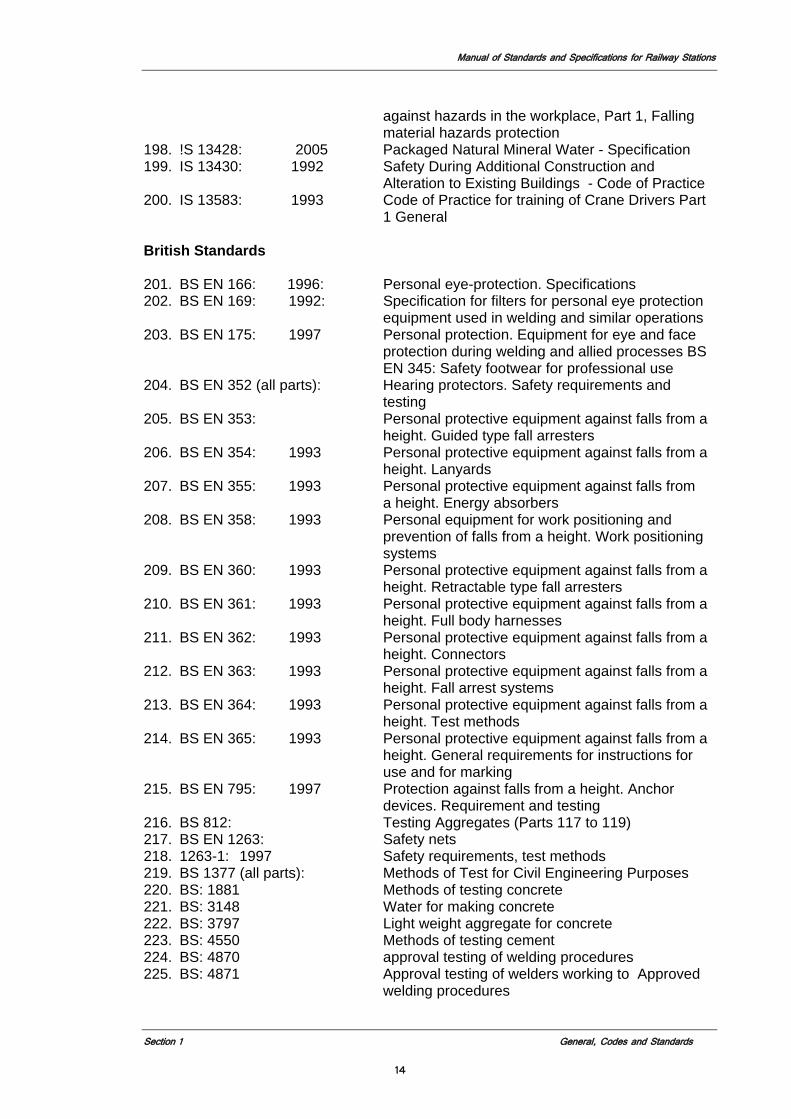
against hazards in the workplace, Part 1, Falling material hazards protection
198. !S 13428: 2005 Packaged Natural Mineral Water - Specification 199. IS 13430: 1992 Safety During Additional Construction and
Alteration to Existing Buildings - Code of Practice 200. IS 13583: 1993 Code of Practice for training of Crane Drivers Part
1 General British Standards
201. BS EN 166: 1996: Personal eye-protection. Specifications 202. BS EN 169: 1992: Specification for filters for personal eye protection
equipment used in welding and similar operations 203. BS EN 175: 1997 Personal protection. Equipment for eye and face
protection during welding and allied processes BS EN 345: Safety footwear for professional use
204. BS EN 352 (all parts): Hearing protectors. Safety requirements and testing
205. BS EN 353: Personal protective equipment against falls from a height. Guided type fall arresters
206. BS EN 354: 1993 Personal protective equipment against falls from a height. Lanyards
207. BS EN 355: 1993 Personal protective equipment against falls from a height. Energy absorbers
208. BS EN 358: 1993 Personal equipment for work positioning and prevention of falls from a height. Work positioning systems
209. BS EN 360: 1993 Personal protective equipment against falls from a height. Retractable type fall arresters
210. BS EN 361: 1993 Personal protective equipment against falls from a height. Full body harnesses
211. BS EN 362: 1993 Personal protective equipment against falls from a height. Connectors
212. BS EN 363: 1993 Personal protective equipment against falls from a height. Fall arrest systems
213. BS EN 364: 1993 Personal protective equipment against falls from a height. Test methods
214. BS EN 365: 1993 Personal protective equipment against falls from a height. General requirements for instructions for use and for marking
215. BS EN 795: 1997 Protection against falls from a height. Anchor devices. Requirement and testing
216. BS 812: Testing Aggregates (Parts 117 to 119) 217. BS EN 1263: Safety nets 218. 1263-1: 1997 Safety requirements, test methods 219. BS 1377 (all parts): Methods of Test for Civil Engineering Purposes 220. BS: 1881 Methods of testing concrete 221. BS: 3148 Water for making concrete 222. BS: 3797 Light weight aggregate for concrete 223. BS: 4550 Methods of testing cement 224. BS: 4870 approval testing of welding procedures 225. BS: 4871 Approval testing of welders working to Approved
welding procedures
Manual of Standards and Specifications for Railway Stations
Section 1 General, Codes and Standards
15
226. BS: 4872 Approval testing of welders when welding procedure approval is not required
227. BS: 5075 Concrete admixtures 228. BS: 5400 (all parts): Steel, concrete and composite bridges 229. BS 5531: 1988 Code of practice for safety in erecting structural
frames 230. BS 5607: 1988 Code of practice for safe use of explosives in the
construction industry 231. BS: 5896 High tensile steel wire and stand for the pre-
stressing of concrete 232. BS 5930: Code of Practice for Site Investigations 233. BS 6031: Code of Practice for Earthworks 234. BS 6164: 1990 Code of practice for safety in tunneling in the
construction industry 235. BS 6349: Code of Practice for Dredging and Land
Reclamation 236. BS 7121 (all parts): Code of practice for safe use of cranes 237. BS 7671: 1992 Requirements for electrical installations. IEE Wiring
Regulations. Sixteenth edition 238. BS 8000 (Part 4): Code of Practice for Water Proofing 239. BS 8000 (Part 5): Code of Practice for Below Ground Drainage 240. BS 8002: Code of Practice for Earth Retaining Structures 241. BS 8004: Code of Practice for Foundations 242. BS 8081: Code of Practice for Ground Anchorages 243. BS 8093: 1991 Code of practice for the use of safety nets,
containment nets and sheets on constructional works
244. BS: 8301 (Section-5) Code of practice for building drainage
Other Standards /Publications
245. UIC/772-R: The International Union of Railways Publication 246. Food Safety and Standards Act 2006 247. Indian Telecom Manual 2007 ASTM Standards 248. ASTM D-1075 Effect of water on cohesion of compacted
bituminous mixtures 249. ASTM D-1143 Test method for piles under static axial comp. test 250. ASTM D-1556 In-situ density by sand replacement 251. ASTM D-1559 Test for resistance to plastic flow of bituminous
mixtures using Marshall apparatus 252. ASTM D-3689 Testing method of testing individual piles under
static axial tensile load 253. ASTM D-4945 Test method for high strain dynamic testing of piles
Ministry Of Shipping, Road Transport and Highways (MORSTH) Publications
254. MOSRTH Specifications for Road and Bridge Works 2001 (Fourth Revision) 255. MOSRTH Standard Plans for Single, Double and Triple Cell Box Culverts with
and without Earth cushion. 256. MOSRTH Type Designs for Intersections on National Highways-1992 257. Manual for Safety in Road Design

Manual of Standards and Specifications for Railway Stations
Section 2 Planning and Design Principles
16
Section 2
Planning and Design Principles
Manual of Standards and Specifications for Railway Stations
Section 2 Planning and Design Principles
17
2.0 PLANNING AND DESIGN PRINCIPLES
2.1 Basic Principles This section is intended to provide the basic principles on which detailed standards and specifications called for in other sections of this Manual are based. These are the overriding principles for the design of stations and in case of any conflict with any specific standard and specification specified in the Manual, requirements specified in this section shall prevail. Station designer may supplement the standards and specifications specified from Section 3 to 7 with other suitable requirements from Codes, Manuals, and Specifications specified in this Manual while complying the Planning and Design Principles specified herein as per section 1.10.7. Use of these principles enables the Station designer to maintain a degree of flexibility and creativity in meeting the objectives of the Station Project specified in the Concession Agreement. The primary goal is to provide a safe, reliable, cost-effective, with easy maintenance and customer-oriented public transportation system. The design of station facilities must therefore address the issues identified here in.
2.2 Architectural Vision Transportation structures have traditionally been the great buildings of urban society. In the major cities of the world, oldest cultures with some of the greatest classical architecture are part of its architectural heritage. . There should be a clear awareness of the importance and value of this along with a clear vision of the future. Railway Station is major gateway and entrance to a city. The station should reflect the character, life style or background of the city or community in which it is located. Hence, a Station building should in its design reflect the culture, historical background and life style of the people of that area. The redeveloped stations, of each Indian city should effectively play a key role in providing the first impression of the city to the visitors arriving by train. The key elements of this vision must, integrate a harmonious and elegant architectural statement with a comfortable and efficient passenger experience, ease of movement, security, safety and accessibility. The Concessionaire may utilize the redevelopment opportunity to include related amenities that will also serve non-passengers, generating revenue as well as creating a facility that will enhance the urban character unique to each city and locality. However, these amenities shall not be considered at the expense of train travelers comfort, efficiency of station and train operations and the effective administration of the Indian Railways. Following shall be the key elements of the architectural vision of the Station:
1. Maximum Passenger Convenience
2. Safety and Security
3. Fast and Efficient Passenger Flow
4. Flexible Interiors
5. A World Class Icon
2.3 Objective of the Station Project 2.3.1 The objective of the Station Project to be developed through this Manual is to upgrade
the existing Station and its surroundings or build a new Station into a world class passenger terminal in a manner which ensures:
Manual of Standards and Specifications for Railway Stations
Section 2 Planning and Design Principles
18
1. Superior services to passengers for the design passenger volume specified in the
CA; 2. Superior train operations (including allied services e.g., parcel, posts etc.) and
maintenance facilities affording greater flexibility and enhanced operational efficiency for IR;
3. Smoother and safer road traffic flow to and from the station, superior road
connectivity with the city and adequate parking within the station premises;
4. Modern and improved offices, residential quarters and other facilities for railway staff on the railway land surrounding the station;
5. Overall improvements in the urban standards of the area for residents and road
commuters;
6. Creation of an urban icon and standard-bearer of a modern vibrant city suiting to its architectural heritage;
7. Least possible inconvenience to passengers, road commuters and residents
during construction; and 8. Harmonious and complementary co-existence of the railway terminal and the real
estate proposed to be developed. 2.3.2 Station projects may include commercial or mixed use development in association with
the development of the station. This manual only addresses the requirements of the station complex. No aspect of the commercial development shall affect the construction, access, or operation of the station. In the event that the station and commercial development share any portion of the structure all services and utilities for the station shall be separate and distinct, all fire and life safety aspects of the station shall be achieved independent of the commercial development (i.e. egress, fire separation), all access shall be separate and distinct (i.e. drop off, station entrance) and shall not be limited in any way visually or physically by the commercial development. Should any portion of the shared structure go through the station building (i.e. structural elements, utilities) the maintenance of those elements and any portion of the station structure they affect will be the responsibility of the commercial development in perpetuity and shall be duly reflected in any title drawn and/or issued to the affected portion of the commercial development.
2.3.3 Compliance to the requirements specified in this Manual should generally lead to the
achievement of above Objective of the Station Project. However, any interpretation or clarification in case of any conflict among various requirements specified in this Manual shall be subject to the stations design’s ability to achieve the objectives specified above.
2.4 Basis of Design Station shall be designed for peak daily and hourly passenger flow in the design year specified in the Concession Agreement and outlined in section 1.5.1. In the absence of such criteria in the CA assume a design year horizon of the proposal year plus 40 years. Station shall be designed to facilitate safe and effective entry and exit of trains, and systematic, safe and efficient collection and dispersal of passengers at the Station. Design of Station shall focus on fully supporting all of the MOR’s operations at the
Manual of Standards and Specifications for Railway Stations
Section 2 Planning and Design Principles
19
station and providing a safe, secure, convenient and comfortable environment for passengers and MOR employees.
2.4.1 Passenger Safety and Security The Station design should promote both real and perceived security for the passenger. Passengers using the Station premises must feel safe in terms of their environment, co-passengers, and staff. The passenger must feel free to seek assistance from any Station staff or the security personnel. Use of the premises of the Station building must be defined from the safety and security aspects for the passengers. Stations should be designed to minimize the possibility of accidents. Particular attention must be paid to the more accident-prone areas, such as the platform and vertical circulation elements, where customer-use characteristics may result in a greater possibility of injury. To the extent practicable, Stations should be designed to be safe and secure without depending on technology and equipment. For security and safety reasons, all pedestrian routes should be well lit and designed with good visibility. Pedestrian routes of travel shall be direct, well lit and clearly defined. Station designs shall incorporate details for maximum accessibility while providing the maximum degree of security protection from crime, attack, and unauthorized entry. The general requirements for this are outlined in Section 4.2 of this manual.
2.4.2 Passenger Convenience and Comfort Station must be provided with all the necessary as well as desirable amenities for the customer/passenger. Amenities should not be limited to the necessary ones, such as public toilets, water points, rest rooms, availability of train information and enquiry counters. They should also include retails, convenience stores, food courts, ATMs and the like. Amenities should be distributed uniformly throughout the public space of the station, and not be concentrated particularly at the entry/exit points where they will interfere with passenger movement. They should be arranged in such a way to help in decentralizing of customer volume and facility maintenance. The design of the Station shall allow maximum customer comfort and convenience. The designer must keep in mind the fact that the transit passenger is a customer and that a primary goal of the Station design is to create a comfortable, convenient, and attractive environment that attracts and retains customers. Design issues that contribute to this include: 1. the minimization of customer travel distances;
2. the provision of pedestrian routes that are as logical and direct as possible;
3. the provision of assisted locomotion (elevators, escalators, moving walkways)
where appropriate and feasible to speed customer flow and assist the mobility impaired or burdened customers; and
4. The provision of adequate customer amenities. The Station shall be designed to enhance the aesthetic and environmental qualities of the path between the station entrance and platform to assure transit customers a pleasant and positive travel experience.
2.4.3 Economy, Efficiency, and Effectiveness Station designs must demonstrate an efficient use of space, material, and structure, which aesthetically integrates lighting, communications, ventilation, electrical, and mechanical systems. The Station design must meet the functional requirements of the Project while maximizing value for the public.
Manual of Standards and Specifications for Railway Stations
Section 2 Planning and Design Principles
20
2.4.4 Precedence of Design Documents
The Concessionaire will be provided with a series of documents on which to base the design of the station. Those documents are to be viewed in the following order of precedence when determining priority of requirements or with conflicting directives. 1. Concessionaire Agreement 2. Technical Schedules attached to Concessionaire Agreement 3. Manual of Standards and Specifications 4. Master Plan and Feasibility Report
2.5 Functional Design 2.5.1 Station shall be designed to achieve full weather protection to every
passenger/customer who enters the station building. 2.5.2 All platforms should be parallel, of same length and in rectangular alignment. See
Section 3. Arrival and departure concourses should be centrally located below and or above the platforms respectively for complete segregation of arriving and departing passengers and similar travel distances for every passenger.
2.5.3 Platforms and departure concourse should each have a common roof with unobstructed
large span structural systems that provides where feasible column free space and unobstructed vision across the length and breadth of platforms and concourse.
2.5.4 Station interiors shall be designed with partition walls that are amenable for flexible
space usage for retails, offices, and other passenger amenities. 2.5.5 Material finishes of elements, such as flooring, walls, structures, furniture, sanitary
fittings, etc. within the public areas of the Station where surfaces either come in direct physical contact of passengers or are visible to them should be highly durable, need low maintenance, less frequent cleaning, and be less amenable to catch dust or cobwebs. See Section 4.6.
2.5.6 Facades must provide maximum amount of natural light feasible. Considerations should
be given to both traditional as well as contemporary material to achieve these goals. 2.5.7 All passenger areas shall be provided with wall and ceiling finishes which do not create
echo and further enable an environment that allows all public announcements to be audible to people everywhere during the maximum rush period. See Section 4.8.
2.5.8 Passengers should be afforded fresh air and comfortable temperatures in all seasons,
through necessary environmental systems in all public areas, see Section 5.5. The station design should maximize the use of natural light and ventilation, see Section 5.2.
2.6 Design Approach and Hierarchy 2.6.1 Design Priority
Design of Railway Station should be done from whole to part, acknowledging the implicit hierarchy of following three categories/orders, each with their own design considerations: 1 Primary Order - Describes the creation of Station volumes through large-scale
engineering. Yard alignment, number and size of platforms, size and location of
Manual of Standards and Specifications for Railway Stations
Section 2 Planning and Design Principles
21
concourses, road networks dissipating the originating/terminating road traffic into the city, capacity of parking, traffic circulation, size of real estate at the station, etc. fall under this category and shall be designed at the primary stage for the Design passenger volume.
2 Secondary Order - Building components, such as detailing of concourse space,
facilities for passengers, operational offices, staircases, escalators, elevators, passageways, entry, exits, roof, ceilings, walls, modal split of parking, type of real estate, development service ducts, etc. fall under this category and shall be designed at the secondary stage for the profile of passengers using the Station;
3 Tertiary Order - Subsidiary products and components layered over secondary
elements to activate and animate stations fall under this category. This includes passenger information system, seating, lighting, advertising, handrails, etc. and shall be designed at the tertiary stage for bringing life and animation in the Station space.
2.6.2 Architectural Heritage and Preservation 2.6.2.1 In India, most of the station buildings were built in the late19th century. Some of them are now designated as heritage structures and need to be preserved. The Station design shall incorporate their preservation and reflect in their aesthetics in the surrounding environment. The new station design shall not isolate the existing heritage structures. The Archaeological Survey of India (ASI) under the provisions of the Ancient Monuments and Archaeological Sites and Remains Act, (AMASR Act) 1958 protects monuments, sites and remains of national importance. Concessionaire has to check, whether the monuments/structures under station complex are protected by AMASR Act, 1958 and if they are protected by above then his subsequent action should be in conjunctions with provision of above act.
2.6.2.2 Station designers of stations whose redevelopment may affect historical areas or structures, potential impact zones should clearly identify such before any deign work is initiated. The Design Team shall develop a design program which identifies those agencies or citizen groups which are likely to be involved and the procedures to be followed for approach of design. The program should also identify significant architectural features which should be taken into account in station and site design. If a portion of a historic structure is to be retrofitted to accommodate a station, security and safety features necessary to preserve the significant historic characteristics of the structure shall be incorporated into the station design.
2.6.3 Circulation and Space Planning The Station design shall provide sufficient circulation elements to allow for the free and safe flow of passengers. Space shall be provided for queuing at all circulation and passenger service elements. The queuing areas should provide sufficient space for passengers to queue at all circulation elements, service areas and decision points without disrupting the movement through other passenger flow routes.
2.6.4 Urban Integration Station entrances provide the link between the Railway Station and the surrounding streets and structures; the entrance must reflect the distinct requirements of both. Station entrances shall provide safe and convenient access to the station for customers while enhancing the surrounding urban environment. In most Indian cities where a railroad enters the city from one end and exits from the other, the city landscape is divided by the railroad track and right of way. In an effort to mitigate such division, the
Manual of Standards and Specifications for Railway Stations
Section 2 Planning and Design Principles
22
MOR requires that the Concessionaire integrate such divided cityscape on both end of the station along the railroad for up to one kilometer at a minimum or as called for in the CA.
2.6.5 The Efficient Movement of Customers/Passengers
The design of the Station shall allow for a free-flow of passengers to avoid a buildup of dangerous congestion within the Station, in particular, on platforms and escalators. Travel distances shall be minimized. Travel routes should be as direct as possible. After customer safety and security, moving customers efficiently through the Station to and from trains is the highest priority of the Station design. Customer flow will take precedence over other Station functions and non-transit facilities in the Station design. From the moment a customer enters the Station premises until he exits, movement must be unimpeded. Each function should have distinct areas and space must be allotted according to the priority of the function. The highest allocation of area must be made for free circulation. Incoming and outgoing volume of passenger must be handled separately. To reduce the waiting passenger’s interference into the circulation area, adequate waiting space is to be provided. See Section 4.5.
2.6.6 Transfers and Interchanges with Other Modes of Transportation The Stations should be merging with the other existing transportation systems. Railway Station design shall facilitate convenient transfers to other Mass Transit System lines and modes of public transportation toward a goal of achieving a seamless local and regional inter-modal public transportation network. The surrounding areas must be planned and designed to maximize free flow traffic movement, and to avoid traffic jams inside and outside the Station campus. Customer must be provided with enough options to leave the station campus as they complete their journey, it could be in the form of regional buses, taxis, auto-rickshaws or the Mass Rapid Transit System (MRTS). All these services must be available to customer within walking distance of 500. See Section 4.5.
2.6.7 Accessibility The station should provide ease of access for all travelers by minimizing physical and psychological impediments to their use of the Station. The positioning and character of the Station’s access points will have a critical influence in satisfying this requirement. The Station design must comply with the requirements of Indian Disability Acts (IDA), and the relevant provisions of American Disabilities Act (ADA) that prescribe the specific configurations and requirements for public facilities to accommodate persons with physical impairments. See Section 4.3.
2.6.8 Visibility and Orientation Clear unobstructed routes for pedestrians circulating through the Station are of the utmost importance, and direct sightlines for all pedestrians and staff are essential. Pedestrians should be able to orientate themselves visually within the building at all times. Decision points, such as ticketing areas, vertical circulation elements, and diverging paths shall be located such that they are clearly identifiable and perceived as part of a logical sequence of travel through the building. Visual connections should be as consistent as possible throughout the building (see Section 4.5). The Station architecture itself shall be the primary means of navigating a path through the building, supported by signage and graphics (see Section 4.9).
Manual of Standards and Specifications for Railway Stations
Section 2 Planning and Design Principles
23
2.7 Environmentally Responsible Design and use of Materials and Resources 2.7.1 A primary objective of the station design will be environmental acceptability,
sustainability and energy efficiency. Station designers will create an environmentally responsible Railway Station that exceeds current standards and practices within the transit industry, creates a healthier, more ecologically responsible Station environment, and complies with all applicable environmental laws. Materials used in the station complex must be eco-friendly. The building should be energy efficient. Rain Water Harvesting, use of Solar Panels for electricity and Waste Management are options to reduce the energy requirement for the Station building. Green/landscaped area must be increased and coordinated with the pedestrian and vehicular traffic. These environmental goals will be achieved through application of the Five Pillars:
1. Energy Efficiency 2. Material and Resource Conservation 3. Indoor Environmental Quality (IEQ) 4. Best Operation and Maintenance 5. Water Conservation and Site Management
The specific objectives and strategies to meet these goals are outlined in Section 5.2.
2.7.2 A preliminary environmental assessment shall be conducted on the proposed
development Site based on existing information and reports prepared within the past 30 years to determine the critical environmental issues that need to be accommodated in the station complex development. Prior to completion of project a complete Environmental Impact Assessment (EIA) as per the requirements of the Ministry of Environments and Forests must be completed and approved by the State Authority having jurisdiction. See section 5.2.
2.8 Division of Operational Responsibility
Concessionaire and MOR will both have operational responsibility in the station structure. The design of the station should reflect this division and ensure that the station layout facilitates MOR’s execution of their role in support of the concessionaire’s operation of the station and can efficiently execute their role in railway operations. Following is a table that delineates their respective roles.
2.8.1 Operational Activities Railways:
1. Train operation a) Train reception/Dispatch (working of power cabin) b) Placement/removal of coaching rake in/from washing lines and stabling
lines including releasing of rake by TXR c) Shunting operation including loco movement, d) Traction changing e) Crew management which includes, booking, signing off, crew changing
involving handing over and taking over of the locomotive. f) Delivering of caution order and other documents to driver/guard g) Operation during emergency: track failure, signal failure, derailments etc.
Manual of Standards and Specifications for Railway Stations
Section 2 Planning and Design Principles
24
2. Infrastructure Operation and Maintenance
a) OHE operation and maintenance b) Signal operation and maintenance c) Track maintenance d) Electricity supply for Traction, Signal, Coach and locomotive
maintenance depot area.
3. Coach maintenance a) Washing Line Operation b) Cleaning of Coaches c) Sick Line Operation d) Watering of coaches e) Train cleaning including system of clean train station f) Pre-cooling and battery charging of coaches in platform lines and
washing and stabling lines. g) Rolling in examination at both ends of platform for all lines. h) Continuity check of brake power and issue of Break Power Certificates
(BPC). i) Axle box feeling (if not covered in rolling in examination) j) Toilet discharge collection facilities (trains with biodegradable and
vacuum collection type toilets). k) Train examination of passing trains rolling in examination.
4. Locomotive Operation
a) Fuelling of locomotives b) Locomotive out pit operation and maintenance c) Attaching/detaching locomotive
5. Information System
a) Coaching operation Information system b) Coach cabinet office working c) Announcements on Passenger Address (PA) system d) Train announcing e) Train Enquiry
6. Ticketing/booking
a) Parcel booking b) Unreserved/reserved ticketing c) Feeding of quota/charting d) Booking at current counter e) Luggage booking f) Ticket Checking
7. Tourism & catering services
a) On-board Catering including base-kitchen and servicing facilities for on-board catering.
b) Bed-roll storage and services to AC coaches in trains (both originating and terminating).
Manual of Standards and Specifications for Railway Stations
Section 2 Planning and Design Principles
25
c) Specified catering stalls, book stalls and miscellaneous passenger related stall in the passenger in the platforms/ concourse area.
d) Tourist reception centre management e) Yatri Niwas and budget hotels built by railways f) Supply and distribution of bottle drinking water g) Food courts, catering stalls of IRCTC relocated in the redeveloped
station.
8. Train Services a) Provision of PCP sets, fire extinguisher, stretcher, first aid box to the
guard b) Posting of charts and delivery of chart to train conductor c) Feeding of Platform nomination in Coach Guidance system d) Handling of driver /guard boxes
9. Parcel Activities
a) Parcel handling b) Activities of SLR/VPU lease holders
10. Security
a) Security of Railway installations by RPF/GRP b) Crime prevention/control by RPF/GRP
2.8.2 Non Operational Activities Concessionaire
1. Utilities a) Water supply including water-harvesting/recycling facilities. b) Electricity Supply except for Traction, Signal, Coach and locomotive
maintenance depot area. c) Drainage Management
2. Passenger Utilities
a) Communication systems operation and maintenance. b) Cloak room management c) Operation and Maintenance of Pay & use toilets/showers d) Provision of Cyber Cafes/ATMs e) Book stalls and miscellaneous stalls in commercial areas of the station
other than those in the passengers concourse f) Food Courts, Catering stalls, other than those in the platforms/passenger
concourse. g) Waiting room (free) h) Paid Lounges i) Escalator/lift upkeep and operation j) Supply and distribution of potable and non potable water including
operation and maintenance of pumping installations, excluding bottled water.
k) Emergency medical care facilities.
3. Cleaning a) Station Cleaning including cleaning of washable aprons.
Manual of Standards and Specifications for Railway Stations
Section 2 Planning and Design Principles
26
b) Staff offices and other building cleaning c) Garbage collection and disposal
4. Inter modal Connectivity
a) Parking management: four wheeler, two wheeler b) Pre paid taxi/auto rickshaw c) Maintenance of circulating area and approach roads including parking
area
5. Building Services a) Maintenance of station lighting, ventilation, air conditioning, power supply
substation b) Station building maintenance and buildings. c) Renovation and up gradation of infrastructure. d) Development and maintenance of drainage system and sewerage
system for yard and circulating area. e) Landscaping of the station complex including horticulture f) Provision of station furniture and its repair. g) Maintenance of parcel-handling conveyors (to be remunerated by
payment of specified charges per parcel.)
6. Railway Staff services a) Maintenance and cleaning of railway staff office b) Crew running room management including house keeping, maintenance
& catering.
7. Commercial development a) Licensing in passenger & concourse area (excluding platforms) except
for the area reserved for Railway use or its Corporations such IRCTC. b) Advertising
8. Security and Safety
a) Access control systems including passenger gets/turnstiles, if any b) Security surveillance system c) Fire safety d) Luggage & parcel scanners.
9. Others
a) Management of Registered Porters and trolley operations.

Manual of Standards and Specifications for Railway Stations
Section 3 Platform Geometry and Services
27
Section 3
Platform Geometry and Services
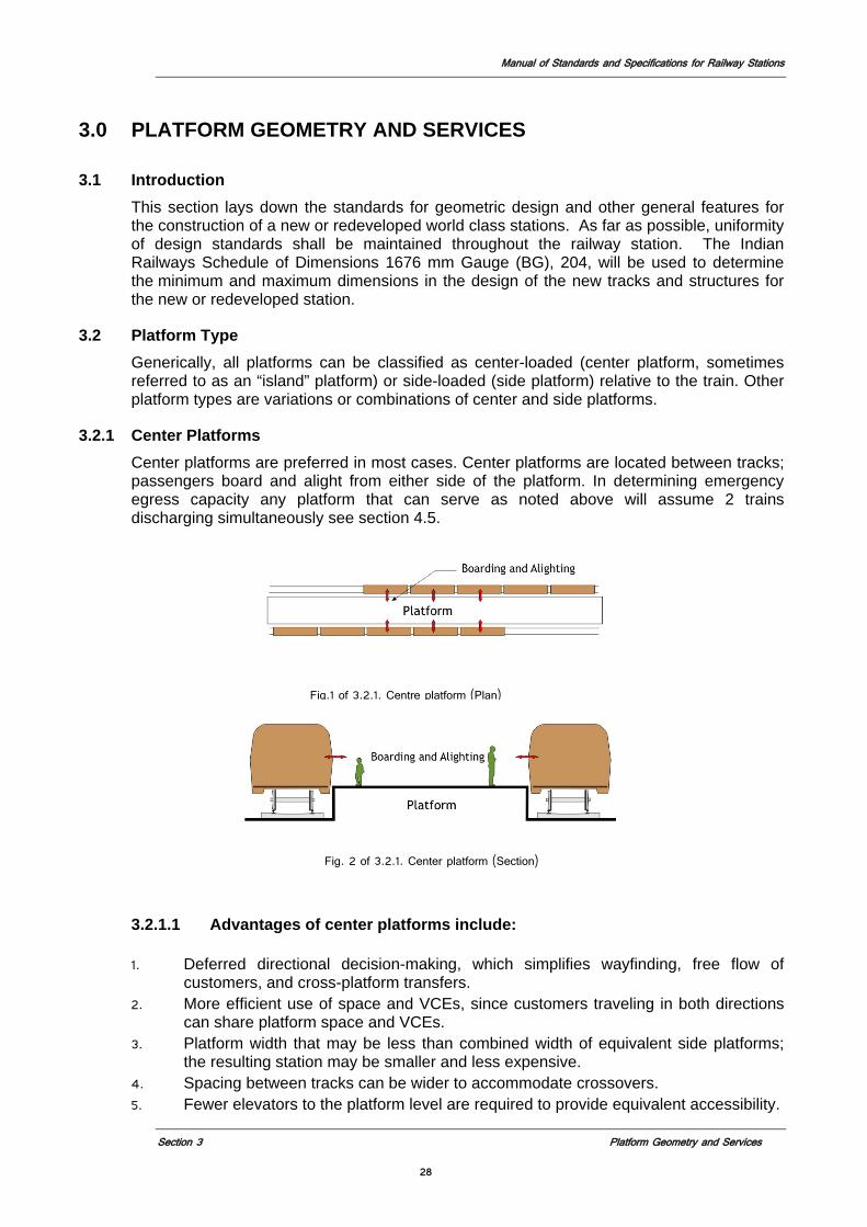
Manual of Standards and Specifications for Railway Stations
Section 3 Platform Geometry and Services
28
3.0 PLATFORM GEOMETRY AND SERVICES
3.1 Introduction This section lays down the standards for geometric design and other general features for the construction of a new or redeveloped world class stations. As far as possible, uniformity of design standards shall be maintained throughout the railway station. The Indian Railways Schedule of Dimensions 1676 mm Gauge (BG), 204, will be used to determine the minimum and maximum dimensions in the design of the new tracks and structures for the new or redeveloped station.
3.2 Platform Type
Generically, all platforms can be classified as center-loaded (center platform, sometimes referred to as an “island” platform) or side-loaded (side platform) relative to the train. Other platform types are variations or combinations of center and side platforms.
3.2.1 Center Platforms
Center platforms are preferred in most cases. Center platforms are located between tracks; passengers board and alight from either side of the platform. In determining emergency egress capacity any platform that can serve as noted above will assume 2 trains discharging simultaneously see section 4.5.
Fig. 2 of 3.2.1. Center platform (Section)
3.2.1.1 Advantages of center platforms include: 1. Deferred directional decision-making, which simplifies wayfinding, free flow of
customers, and cross-platform transfers. 2. More efficient use of space and VCEs, since customers traveling in both directions
can share platform space and VCEs. 3. Platform width that may be less than combined width of equivalent side platforms;
the resulting station may be smaller and less expensive. 4. Spacing between tracks can be wider to accommodate crossovers. 5. Fewer elevators to the platform level are required to provide equivalent accessibility.
Fig.1 of 3.2.1. Centre platform (Plan)
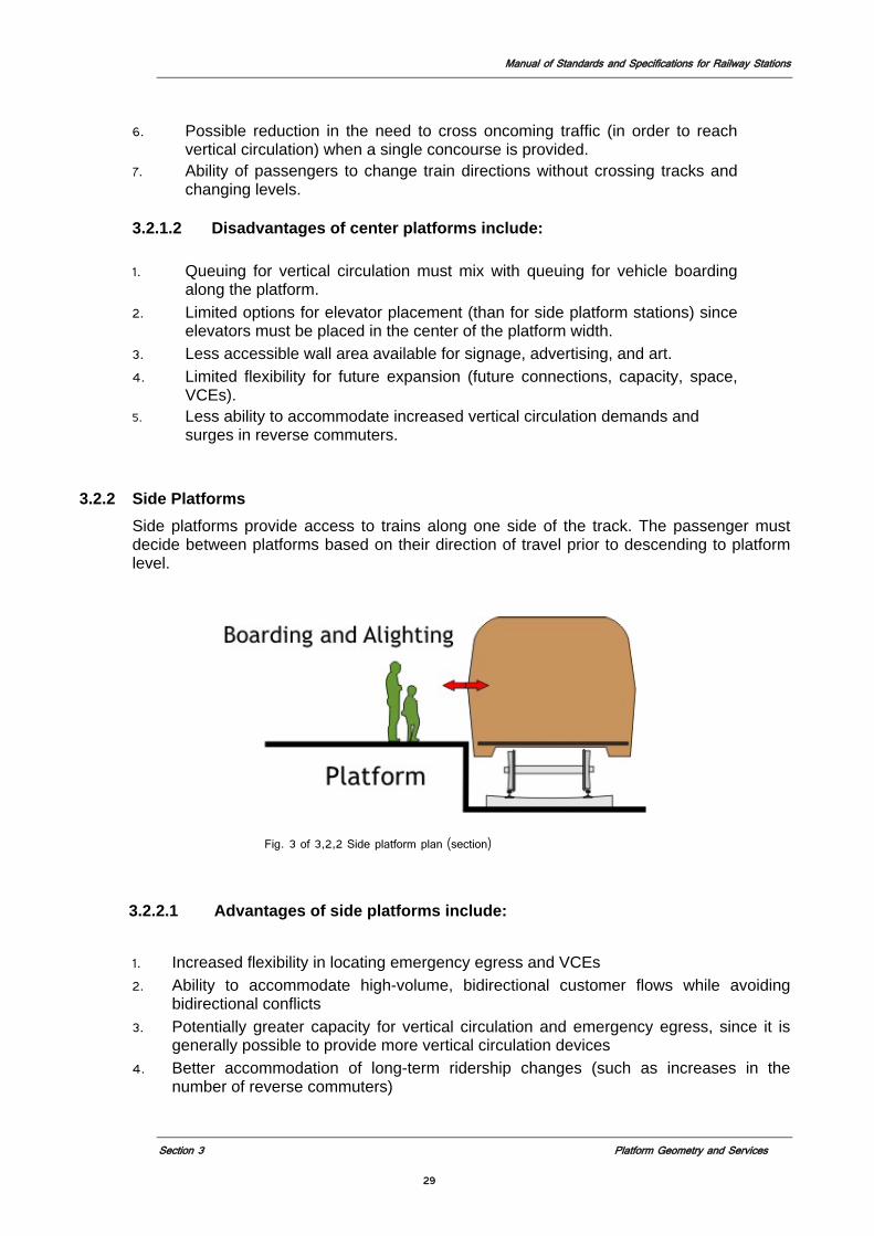
Manual of Standards and Specifications for Railway Stations
Section 3 Platform Geometry and Services
29
6. Possible reduction in the need to cross oncoming traffic (in order to reach vertical circulation) when a single concourse is provided.
7. Ability of passengers to change train directions without crossing tracks and changing levels.
3.2.1.2 Disadvantages of center platforms include:
1. Queuing for vertical circulation must mix with queuing for vehicle boarding along the platform.
2. Limited options for elevator placement (than for side platform stations) since elevators must be placed in the center of the platform width.
3. Less accessible wall area available for signage, advertising, and art. 4. Limited flexibility for future expansion (future connections, capacity, space,
VCEs). 5. Less ability to accommodate increased vertical circulation demands and
surges in reverse commuters.
3.2.2 Side Platforms Side platforms provide access to trains along one side of the track. The passenger must
decide between platforms based on their direction of travel prior to descending to platform level.
Fig. 3 of 3,2,2 Side platform plan (section)
3.2.2.1 Advantages of side platforms include:
1. Increased flexibility in locating emergency egress and VCEs 2. Ability to accommodate high-volume, bidirectional customer flows while avoiding
bidirectional conflicts 3. Potentially greater capacity for vertical circulation and emergency egress, since it is
generally possible to provide more vertical circulation devices 4. Better accommodation of long-term ridership changes (such as increases in the
number of reverse commuters)
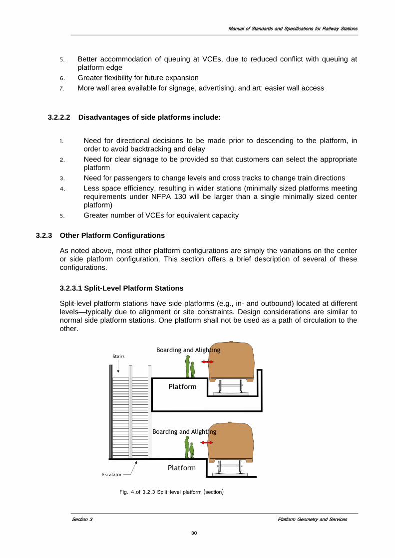
Manual of Standards and Specifications for Railway Stations
Section 3 Platform Geometry and Services
30
5. Better accommodation of queuing at VCEs, due to reduced conflict with queuing at platform edge
6. Greater flexibility for future expansion 7. More wall area available for signage, advertising, and art; easier wall access
3.2.2.2 Disadvantages of side platforms include:
1. Need for directional decisions to be made prior to descending to the platform, in order to avoid backtracking and delay
2. Need for clear signage to be provided so that customers can select the appropriate platform
3. Need for passengers to change levels and cross tracks to change train directions 4. Less space efficiency, resulting in wider stations (minimally sized platforms meeting
requirements under NFPA 130 will be larger than a single minimally sized center platform)
5. Greater number of VCEs for equivalent capacity 3.2.3 Other Platform Configurations
As noted above, most other platform configurations are simply the variations on the center or side platform configuration. This section offers a brief description of several of these configurations.
3.2.3.1 Split-Level Platform Stations
Split-level platform stations have side platforms (e.g., in- and outbound) located at different levels—typically due to alignment or site constraints. Design considerations are similar to normal side platform stations. One platform shall not be used as a path of circulation to the other.
Fig. 4.of 3.2.3 Split-level platform (section)
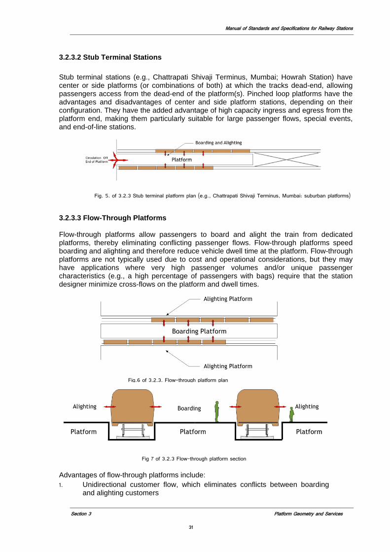
Manual of Standards and Specifications for Railway Stations
Section 3 Platform Geometry and Services
31
3.2.3.2 Stub Terminal Stations
Stub terminal stations (e.g., Chattrapati Shivaji Terminus, Mumbai; Howrah Station) have center or side platforms (or combinations of both) at which the tracks dead-end, allowing passengers access from the dead-end of the platform(s). Pinched loop platforms have the advantages and disadvantages of center and side platform stations, depending on their configuration. They have the added advantage of high capacity ingress and egress from the platform end, making them particularly suitable for large passenger flows, special events, and end-of-line stations.
Fig. 5. of 3.2.3 Stub terminal platform plan (e.g., Chattrapati Shivaji Terminus, Mumbai: suburban platforms)
3.2.3.3 Flow-Through Platforms Flow-through platforms allow passengers to board and alight the train from dedicated
platforms, thereby eliminating conflicting passenger flows. Flow-through platforms speed boarding and alighting and therefore reduce vehicle dwell time at the platform. Flow-through platforms are not typically used due to cost and operational considerations, but they may have applications where very high passenger volumes and/or unique passenger characteristics (e.g., a high percentage of passengers with bags) require that the station designer minimize cross-flows on the platform and dwell times.
Fig 7 of 3.2.3 Flow-through platform section
Advantages of flow-through platforms include: 1. Unidirectional customer flow, which eliminates conflicts between boarding
and alighting customers
Fig.6 of 3.2.3. Flow-through platform plan
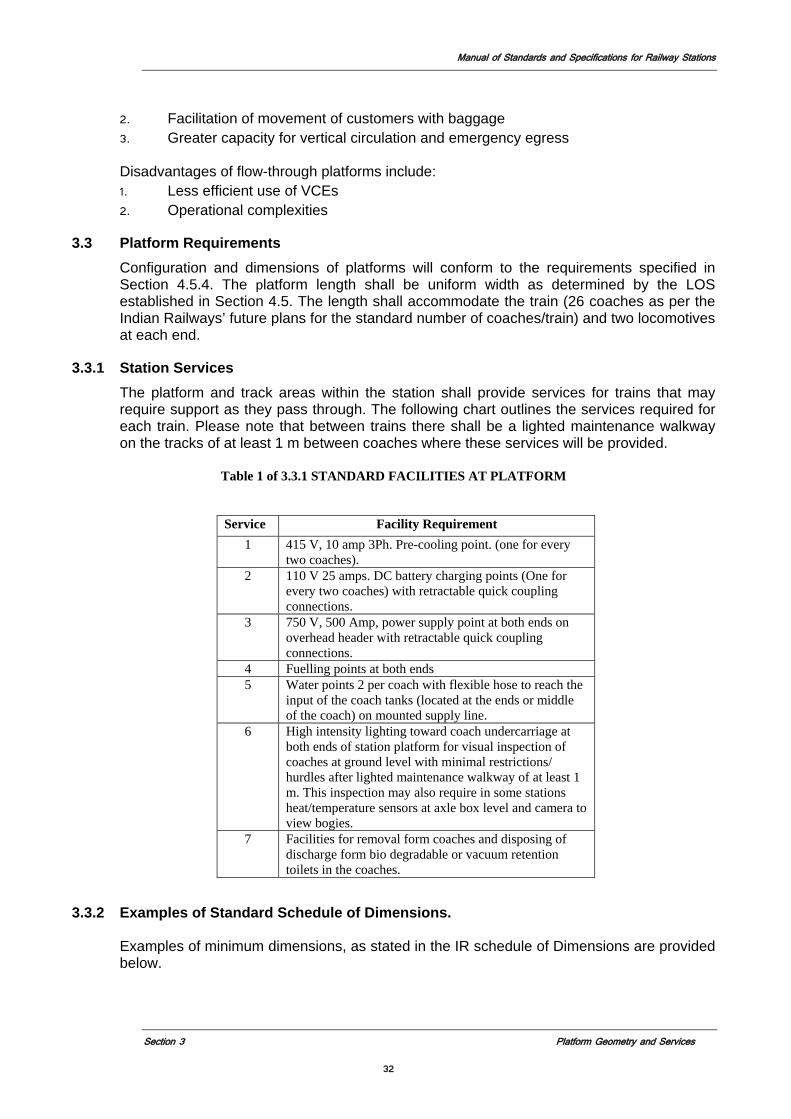
Manual of Standards and Specifications for Railway Stations
Section 3 Platform Geometry and Services
32
2. Facilitation of movement of customers with baggage 3. Greater capacity for vertical circulation and emergency egress
Disadvantages of flow-through platforms include:
1. Less efficient use of VCEs 2. Operational complexities
3.3 Platform Requirements Configuration and dimensions of platforms will conform to the requirements specified in Section 4.5.4. The platform length shall be uniform width as determined by the LOS established in Section 4.5. The length shall accommodate the train (26 coaches as per the Indian Railways’ future plans for the standard number of coaches/train) and two locomotives at each end.
3.3.1 Station Services The platform and track areas within the station shall provide services for trains that may
require support as they pass through. The following chart outlines the services required for each train. Please note that between trains there shall be a lighted maintenance walkway on the tracks of at least 1 m between coaches where these services will be provided.
Table 1 of 3.3.1 STANDARD FACILITIES AT PLATFORM
3.3.2 Examples of Standard Schedule of Dimensions.
Examples of minimum dimensions, as stated in the IR schedule of Dimensions are provided
below.
Service Facility Requirement 1 415 V, 10 amp 3Ph. Pre-cooling point. (one for every
two coaches). 2 110 V 25 amps. DC battery charging points (One for
every two coaches) with retractable quick coupling connections.
3 750 V, 500 Amp, power supply point at both ends on overhead header with retractable quick coupling connections.
4 Fuelling points at both ends 5 Water points 2 per coach with flexible hose to reach the
input of the coach tanks (located at the ends or middle of the coach) on mounted supply line.
6 High intensity lighting toward coach undercarriage at both ends of station platform for visual inspection of coaches at ground level with minimal restrictions/ hurdles after lighted maintenance walkway of at least 1 m. This inspection may also require in some stations heat/temperature sensors at axle box level and camera to view bogies.
7 Facilities for removal form coaches and disposing of discharge form bio degradable or vacuum retention toilets in the coaches.
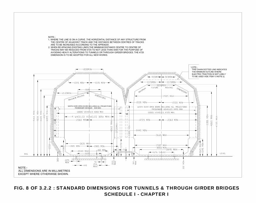
�����
��������� ������������ �� �������������������������������
������������������������������������������������������������������� ������������� ���������!����������������������������������!����������������������������������������"������������������������������� ��� � ����������������������������!� �������������� #$"%������������##&%������������������������������������������������������������������������#$"%�� �����������������������������!��
����������������������������������� ��� � ��������������������������������!����������������� �*����+,-�
������������������������������ �����������������������#.#. ��
FIG. 8 OF 3.2.2 : STANDARD DIMENSIONS FOR TUNNELS & THROUGH GIRDER BRIDGESSCHEDULE I - CHAPTER I
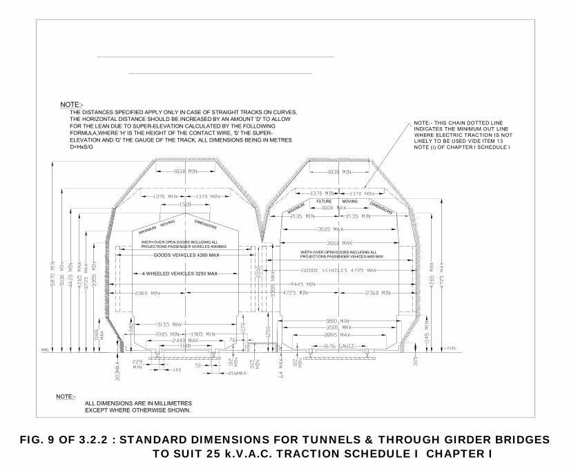
��
��������� ������������ �� �������������������������������
������������������������������������������������������!���������������������������������������������������� ����0�0�������������������������������������������������������� ��������0�0����������������������������0�0��������������������0�0�����������������!���� �������������� ������1�2�3�
������������������������������ �����������������������#.#. ��
������������#"(% ��
��� �
����� �� �������
������������������������������ �����������������������##&% ��
������������������������������������ ��� � ��������������������������������!����������������� �*����+,-������������������
���
� ������ ����� �� �������
#�������������*"%. ��
FIG. 9 OF 3.2.2 : STANDARD DIMENSIONS FOR TUNNELS & THROUGH GIRDER BRIDGESTO SUIT 25 k.V.A.C. TRACTION SCHEDULE I CHAPTER I
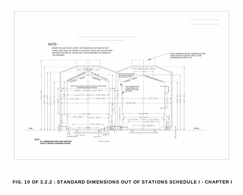
��
��������������������� �������������� �� ����������������������������������������������
����������������������������������������������������������������� ������������� ���������!����������������������������������!����������������������������������������
��� �
����� �� �������
������ ��� � ������������������������������������!����������������+��� �.+,,--
��� ���
��� �
�����
�� ���
���� ����������������������
����� ��������������������������������������������
���� ���������������������������������� ����������
��� �
�����
������������������������������ �����������������������#.#. ��
�� ������������������!
FIG. 10 OF 3.2.2 : STANDARD DIMENSIONS OUT OF STATIONS SCHEDULE I - CHAPTER I
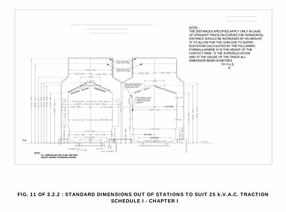
��
��������������������� �������������� �� ����������������������������������������������
���
��� � �����
�� �������
�������������������������������������������������������!��������������������������������������������������� ����0�0�������������������������������������������������������� ��������0�0����������������������������0�0�������������������0�0�����������������!���� ������������� ������1�2��
"�*% ��
"##. ���($% ��
���� ���������������������������������� ���������
����� ��������������������������������������������
������������������������
�������������������������
��� �
���
����
������
�
��� �
�����
�� ��������������������!
����������������������
FIG. 11 OF 3.2.2 : STANDARD DIMENSIONS OUT OF STATIONS TO SUIT 25 k.V.A.C. TRACTIONSCHEDULE I - CHAPTER I
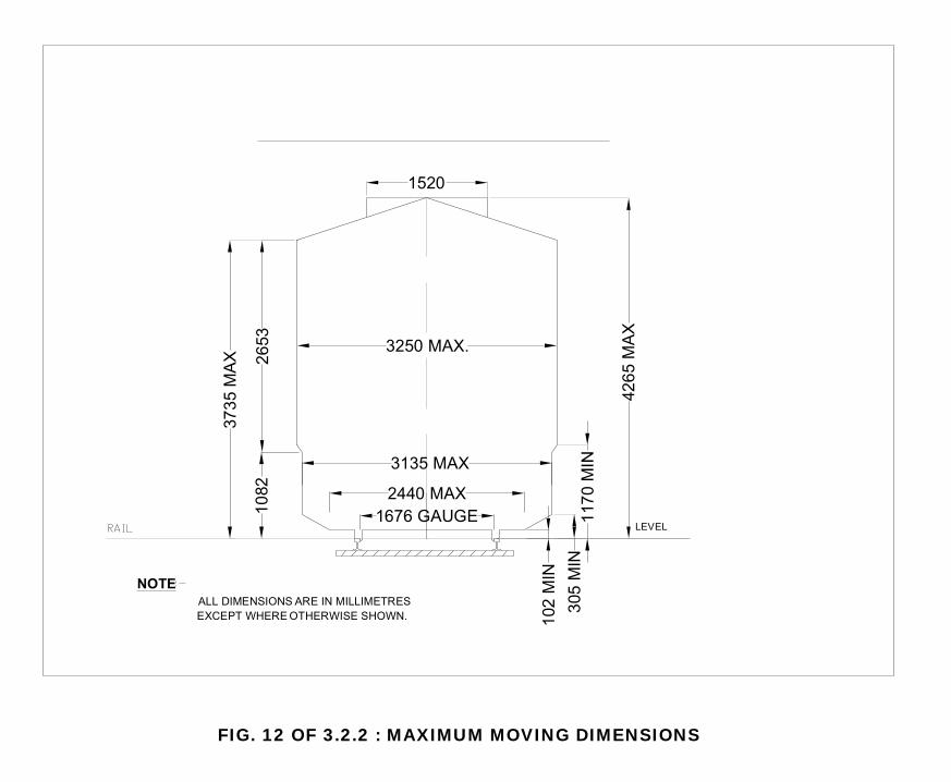
��
�($(�����"##. ��
*�*% ��
��$.
��
*.% ��
�." ��
���
*"%. ���
������� ������������� �� �����
������������������������������������������
�%".
#"(%
��
�.4"
*$*%
�� "(
%*
FIG. 12 OF 3.2.2 : MAXIMUM MOVING DIMENSIONS
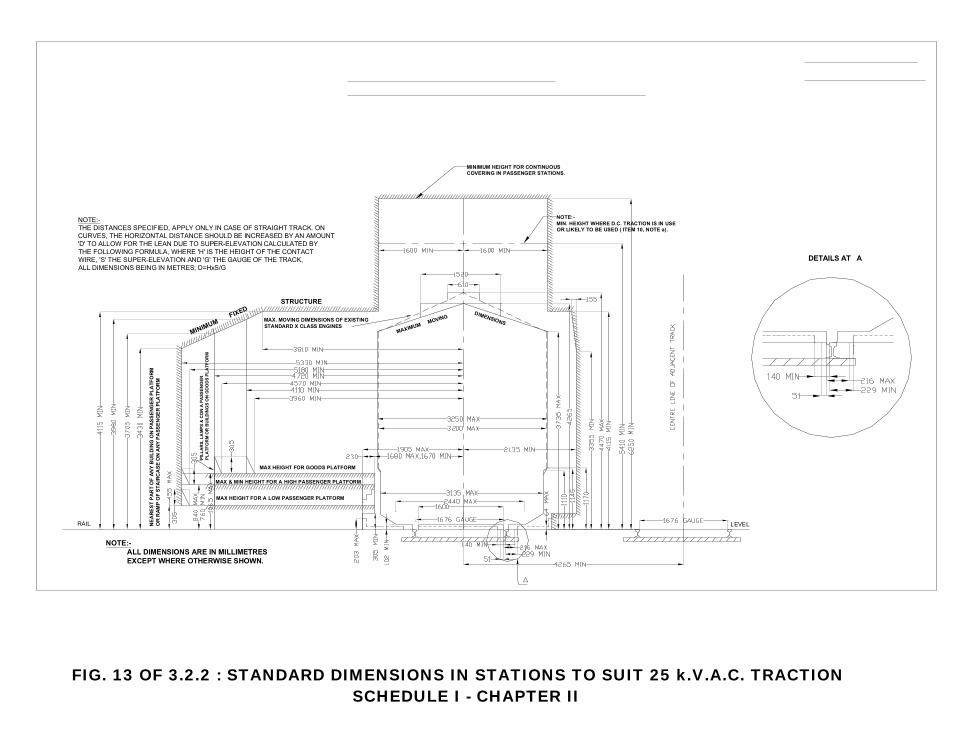
��
������������������� �������������� �� ��������������������������������������������
�������������������������������������������������������!��������������������������������������������������� ����0�0�������������������������������������������������������� ��������0�0����������������������������0�0��������������������0�0�����������������!���� �������������� �����5�1�2�3�
���������������!�"������������������������
���� �����������������!��������������� �
��#� ����������������������������������
�������������������������������
������������������������
������ �������������������������������������������$�!����"�������%���� ��&'������()�
��� � �����������������������������������������������������
�� � �
���� �����
�� �������
����'� ���#���������������
����� ����"���������������������� �
��� ���
��� �������� ����������������������������������������
����������
��� � ����
��������
���������
FIG. 13 OF 3.2.2 : STANDARD DIMENSIONS IN STATIONS TO SUIT 25 k.V.A.C. TRACTIONSCHEDULE I - CHAPTER II
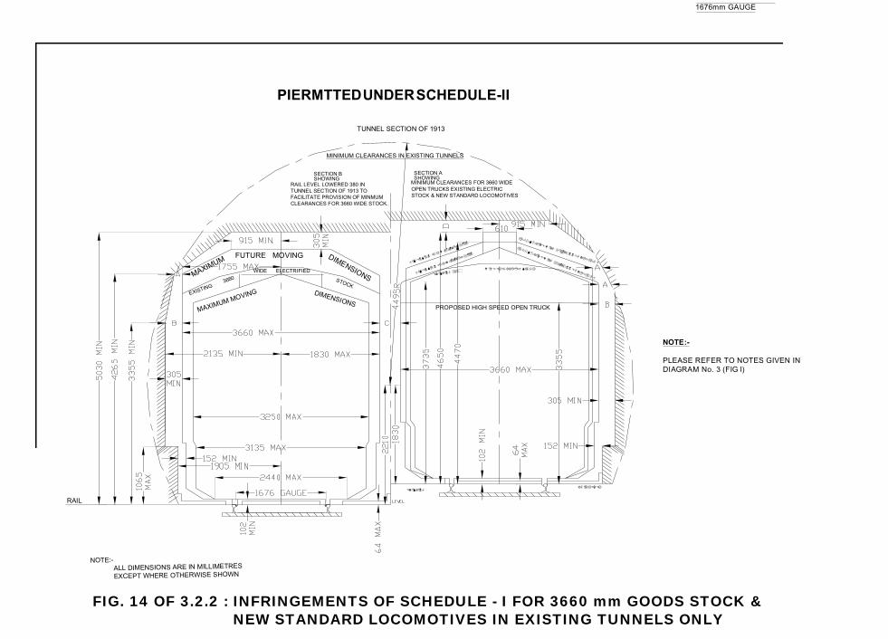
��
���
� ������ ����� �� �������
��� � �������������������������
���������������
������������*4.�����������������&�*���������������������� �� � ������������*((.��������!�
���������������
��� � ������������*((.������������!��������������������!��������������� ������
����������
����
� ��� �
������������
����� � ���������������� ���������� ��
� � ���������������� ���������� ���������
����������������������� �
���������
����
� ��� �
��������
��������
��������� ������������ �� ������������������������������
���������������&�*
�������������������������!
��������
*((.
��������������
��� � ����� �� �������
���
������
������������������������������ �'�*+����-
�($())�����
����!
�FIG. 14 OF 3.2.2 : INFRINGEMENTS OF SCHEDULE - I FOR 3660 mm GOODS STOCK &
NEW STANDARD LOCOMOTIVES IN EXISTING TUNNELS ONLY
���� �������������������
Manual of Standards and Specifications for Railway Stations
Section 4 Station Design
33
Section 4
Station Design
Manual of Standards and Specifications for Railway Stations
Section 4 Station Design
34
4.1 GENERAL
4.1.1 Unless stated otherwise in this Manual, the whole of architectural works for the Project Station shall be constructed to comply with the relevant laws and regulations of the Indian Government or the State Government in which the Station is located, as well as complying with the requirements of the local authorities, Fire Regulations, and such other additional requirements as may be stated in the Manual elsewhere and in the Concession Agreement.
4.1.2 Unless stated otherwise in the Manual the design requirements relating to fire safety
and escape shall be generally in accordance with NFPA 130 Standard for Fixed Guide way Transit Systems.
Manual of Standards and Specifications for Railway Stations
Section 4 – Station Design Safety and Security
35
4.2 SAFETY AND SECURITY
4.2.1 Introduction This chapter addresses static and traditional threats to the safety of people and facilities. It also outlines briefly dynamic temporary threats from non traditional sources. The objective is to minimize the potential impact on passengers and minimize dependency on technology and equipment. It contains the following: 1. Station perimeter - definition of separation between station operating area and
remainder of station complex which will include other structures. 2. Appropriate features to support life safety and security strategy. 3. Conformance with appropriate fire and life safety codes 4. Provisions regarding sufficient areas and means of egress to facilitate safe
movement of passengers and staff at peak times, disrupted conditions and/or emergencies.
5. Provisions regarding maintaining tenable conditions during station evacuation in the event of an emergency
6. Provision of fire detection and alarm systems including fire detection systems, HPI, and audible and visible alarms.
7. Provision of fire detection and suppression systems 8. Surveillance and access control systems 9. Central security control, monitoring and response
4.2.2 Safety Management Methods Safety in the heavy rail transit industry involves:
1. Hazard Identification and Management 2. Quantitative Risk Assessment (QRA) 3. Design Review 4. Traceability from Initial Design to Acceptance Testing (Safety Certification) 5. A Separate Safety Management and Reporting Function 6. Training of station staff in assessment and management of emergency
condition
4.2.3 Security The station area and site which comprises the ingress and egress to the station need to be defined as a separate distinct area within the overall station complex. Safety and security provisions shall be included in design to address all sections of the separation of station operating area and the remainder of the station complex. This should include above and below ground parking all pedestrian crossings and any non station structure directly adjacent to station operating area. 4.2.3.1 Station Site Perimeter Security The border of the station operating area starting at the street where vehicular access is provided is determined by the separation of the station area from the remainder of the station complex through the exterior of the actual building structure to the border of the area where vehicular egress is provided to the street. This shall be defined as the Station perimeter. Security provisions for the station perimeter shall be as follows: 1. Vehicular access – All vehicular access points shall have infrastructure
provisions for CCTV surveillance and automatic vehicle scanner installed underground at vehicle entry points and connected to central control room for
Manual of Standards and Specifications for Railway Stations
Section 4 – Station Design Safety and Security
36
monitoring. Concessionaire agreement shall stipulate where actual equipment will be installed.
2. Station Entrance Protection – All station entrances pedestrian access ways that
are adjacent to vehicular pathways and must be provided with high security bollards with provision for removal of bollards for access of emergency and service vehicles. See section 4.11.6.8.
3. Pedestrian access – All pedestrian access either from the street or the other
exterior areas sections of the station complex shall be designed as to permit barrier separation form the station operating area in the event of an emergency. Concessionaire agreement shall stipulate whether where and what actual equipment will be installed.
4. Open areas – all other exterior areas shall be designed as to create physical
separation of a minimum of 1.5m high which will not permit vehicle passage between station operating area and the rest of the station complex.
5. Co-located Structures – Any structure that shares a wall with the station
structure or is on the perimeter boundary shall have no opening into the station area. In the event that such an opening is required an intrusion detection and alarm system integrated into to the station security command center shall be provided.
4.2.3.2 Parking and Vehicular Access Parking should be located away from the station structure and separated by physical barriers as per section 4.2.3.1 or by bollards. In the even that parking is provided underground the provisions of 4.2.3.1 shall apply. Parking that is located underneath the station platforms shall be have these provisions at every access and egress point. Vehicular access to station operation area should be limited to the drop off points and preferably should come directly from the street and not through the other parts of the station complex. In the event that vehicular access can come directly from the other parts of the station complex vehicular access should be treated as called for in section 4.2.3.1. 4.2.3.3 Path of Pedestrian Travel Security provisions are required at each part of the passenger’s movement through the station. Following are the features required at each juncture. 1. Station Entrance – Provide CCTV camera with adequate resolution to permit use
of facial recognition technology at all station entrances with enough cameras to cover entire station entrance area. Locate station information signage in such a way as to not result in passenger queuing at entrance area.
2. Paid Area – provide in each access point to paid area, infrastructure provisions
for at least one of the entrance gate to each access point in the direct area of passenger travel (not segregated into separate area) with the following:
• CCTV camera with adequate resolution to permit use of facial recognition
technology. • Body scan machine • Luggage scanning machine (i.e. x-ray scanner on conveyor)
Manual of Standards and Specifications for Railway Stations
Section 4 – Station Design Safety and Security
37
3. Entrance to paid area is to be configured so as to permit the operation of this security station without impact on the movement of passengers at the other entrance gates. Concessionaire agreement and appended technical schedules shall stipulate where and what actual equipment will be installed.
4.2.3.4 Command Center
The station shall be provided with a security command center to be co-located with stationmaster’s complex. It shall have a separate set of rooms as described below but may share support facilities for staff such as lockers toilets and shower facilities with the station masters staff. 1. All surveillance, emergency communication systems, intrusion detection if
applicable and any other security feature provided in the station design that is not part of the fire command center, shall be routed to the security command center.
2. Command center size will depend on the station capacity, size and configuration.
Following are the lists of sample spaces that may comprise the command center. Concessionaire agreement shall stipulate what additional spaces and/or features for security center will be required at each station.
4.2.3.5 Surveillance Systems
The station shall be provided with a centralized CCTV system distributed throughout the entire station (see Section 4.11.6.3) 1. Coverage – Cameras will be covering all operating areas and will include but not
be limited to:
• All Vehicular ingress and egress. • All main pedestrian entry and egress points to station structure (including
multi-modal connections whether at, above or below ground level. • All main entry points to paid area. • On main concourse in all areas cameras will not be more than 100m from
any point. • On all platforms in all areas cameras will not be more than 100m from
any point.
2. System - Cameras should have adequate resolution to get clear facial images at 100m and system shall be compatible with current facial recognition technology. All cameras should be connected to central command center and displayed on zoned multi screen CRT’s, that cycle their respective zones in intervals of not more than 30 seconds. Camera infrastructure should provide for central notification and location when unit is not operational..
4.2.3.6 Emergency Communications Station will be provided with a central emergency communications system (see section 4.11.6.7) that will consist of: 1. PBX – Point to point type system with centralized bases at command center, tied
into IR administrative communication network, with access to station master’s complex at command center and at building management center. Distribution should include all appropriate station staff including maintenance and repair operations.
Manual of Standards and Specifications for Railway Stations
Section 4 – Station Design Safety and Security
38
2. Help Point Intercoms (HPI) – These customer service information units shall
have a two way intercom that annunciates at the central command center. They shall be located such that the travel distance from any point in the public area shall not exceed 100m. Such emergency devices shall be distinctive in color and their location shall be indicated by appropriate signs.
3. Public Address (PA) System – The PA system for train information and
announcements shall be designed in such a way that the security command center would also have access to operating system, so that in case of emergency conditions and situations the security staffs can assist and help in coordinating with the emergency operations. PA system will normally be under the control of station master as part of the central train information system for the station.
4.2.3.7 Awareness and Training Public and station staff awareness of the security provisions and requirements of the station’s operation is essential in maintaining a viable security program in large and dynamic public facilities like a station. The Concessionaire in conjunction with MOR should develop the following: 1. Awareness Program – Development and implementation of a public safety
awareness campaign for staff and passengers at each station regarding the safety requirements and features of the new stations.
2. Training – development and implementation of safety training plan that includes
drills and the monitoring and response to life safety emergency conditions.
4.2.3.8 Emergency Preparedness
Dynamic temporary threats from non traditional sources also need to be incorporated into the stations emergency response plan. The approach to handle them begins with the definition of the potential threat and the critical assets (e.g. people, operational facilities) whose protection is necessitated by the threat. This is essentially a planning process that produces an emergency response plan. In some cases the analysis may result in physical infrastructure adjustments. However it depends primarily on the physical protection in place from the traditional safety protocols and features such as fire/life safety and an operational strategy that will effectively mitigate the threat. Critical steps in this analysis and planning are: 1. Threat assessment 2. Evaluation of Asset vulnerability
3. Assessment of existing safety and security capability both in physical plant and
in existing operations (e.g. available staff at station, police and fire dep’t response capabilities)
4. Implementation of additional protocols and physical features to address threat
operationally and at physical plant.
5. Development of an operational emergency response plan that • Incorporates and coordinates existing response capabilities (police and
fire) and provides for additional ones (e.g. chemical. Biological)
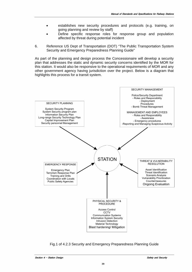
Manual of Standards and Specifications for Railway Stations
Section 4 – Station Design Safety and Security
39
• establishes new security procedures and protocols (e.g. training, on going planning and review by staff)
• Define specific response roles for response group and population affected by threat during potential incident
6. Reference US Dept of Transportation (DOT) “The Public Transportation System
Security and Emergency Preparedness Planning Guide”
As part of the planning and design process the Concessionaire will develop a security plan that addresses the static and dynamic security concerns identified by the MOR for this station. It would also be responsive to the operational requirements of MOR and any other government agency having jurisdiction over the project. Below is a diagram that highlights this process for a transit system.
Fig.1 of 4.2.3 Security and Emergency Preparedness Planning Guide
Manual of Standards and Specifications for Railway Stations
Section 4 – Station Design Safety and Security
40
4.2.4 Fire and Life Safety Standards The fire and life safety features that will comprise of the requirements for the station includes the following:
1. Fire detection, annunciation, suppression and smoke and fire control systems. 2. Compartmentation – Fire and smoke resistant requirements and features of
walls doors floors and ceilings separating different parts of the all of the stations enclosed spaces.
3. Evacuation - Passenger movement in station through designated escape routes in case of fire or other emergency.
4. Removal or minimizing obstructions and Impediments to passenger movement –minimizing of columns and other structural or construction elements on platforms, clear floor space along platform , edges, straight alignment along platform edges.
5. Safety Surfaces – e.g. Textured and color differentiated strip on platform edges, Stairways with non-slip Nosing.
6. Mobility Impaired – Elevators and ramps for reducing hazard for elderly and disabled passengers, for passengers carrying baggage. Supervised evacuation route for elderly and disabled passengers in case of emergencies.
7. Public address system - Annunciate safety messages via emergency voice alarm communications system.
8. Signage- Clear emergency signage emergency egress routes. 9. Maintenance – Establishment of testing and repair protocols for all emergency
safety equipment.
4.2.4.1 Codes and Standards
The station design will conform to the latest editions of the following codes and standards in the precedence order described below (all codes shall be the latest edition unless otherwise noted:
Table 1 of 4.2.4: Codes and standards for Station designing
Overall Station Configuration
NFPA 130 (USA) National Building Code (India)
NFPA shall be the controlling code, where it is silent the NBC will apply. Conflicts between these codes and any other applicable local codes will need to be resolved in consultation with the local authority having jurisdiction as per NFPA 72
Egress NFPA 101 sections referenced in NFPA 130 National Building Code
Fire Alarm, Detection and Suppression
NFPA 72 National Building Code
Portable Fire Extinguishers
NFPA 10 National Building Code
Ancillary Spaces
NFPA 251 National Building Code
Electrical NFPA 70 BIS (India)
This code is to serve as a guide to the required fire safety characteristics of the wiring. Construction is to be as requirements of the Bureau of Indian Standards and Indian Standards institute.
Manual of Standards and Specifications for Railway Stations
Section 4 – Station Design Safety and Security
41
Fire Safety Risk Assessment
Transportation Risk Assessment Transport Premises and Facilities (UK)
This code is to serve as a guide to facility assessment to be used in conjunction with any applicable local codes.
Review and Oversight
Handbook of Transit Safety and Security Certification (USA)
This code is to serve as a guide to coordination of life safety design compliance to be used in conjunction with any applicable local codes.
4.2.4.2 Design Fire Scenarios
For the purpose of Fire scenarios that are to be considered, but not limited to, for the design of the stations are: 1. Fire on a Passenger Train at the station. 2. Trash/Baggage Fire in open passenger or service area. 3. Concession Area Fire in open passenger area.
Fires in enclosed areas are addressed by the compartmentation, detection, and fire suppression features of that particular space as called for in the respective applicable codes. For stations with unusual configuration or features that are not accommodated in the referenced codes, a fire safety engineering study to be done as per the requirements of NFPA130 of fire scenarios and corresponding features and requirements. 4.2.4.3 Fire Initiation and Development
In addition to the fire protection and suppression, the fire and life safety strategies include reduction in the frequency of fire ignition, and the rate of development of a fire, and its related smoke and heat production. This requires:
1. Establishment of station maintenance and management procedures that address
trash collection and storage that minimize the possibility of fire caused by operating conditions and the availability of materials to feed a fire once ignited .These includes trash collection, maintenance work such as grinding and welding (hot work) and storage of materials in mechanical spaces. Refer to Transportation Risk Assessment, transport premises and facilities (UK).
2. Surface materials to minimize the spread of fire once ignited shall have the
following attributes:
Public Areas Class A All Egress Areas not part of public area Class B Table 2 of 4.2.4: Material Classification
Classification Flame Spread Rating Smoke Development A 0-25 0-450 B 26-75 0-450 C 76-200 0-450
In addition to the storage of flammable and combustible materials such as cleaning products and implements will need to be managed to minimize the possibility of fire ignition and containment in the event of ignition.
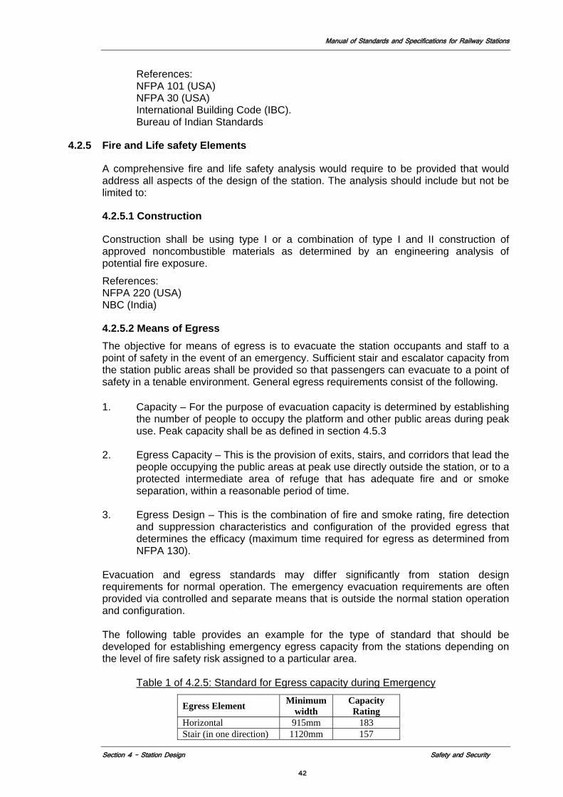
Manual of Standards and Specifications for Railway Stations
Section 4 – Station Design Safety and Security
42
References: NFPA 101 (USA)
NFPA 30 (USA) International Building Code (IBC).
Bureau of Indian Standards
4.2.5 Fire and Life safety Elements
A comprehensive fire and life safety analysis would require to be provided that would address all aspects of the design of the station. The analysis should include but not be limited to:
4.2.5.1 Construction
Construction shall be using type I or a combination of type I and II construction of approved noncombustible materials as determined by an engineering analysis of potential fire exposure.
References: NFPA 220 (USA) NBC (India)
4.2.5.2 Means of Egress The objective for means of egress is to evacuate the station occupants and staff to a point of safety in the event of an emergency. Sufficient stair and escalator capacity from the station public areas shall be provided so that passengers can evacuate to a point of safety in a tenable environment. General egress requirements consist of the following.
1. Capacity – For the purpose of evacuation capacity is determined by establishing
the number of people to occupy the platform and other public areas during peak use. Peak capacity shall be as defined in section 4.5.3
2. Egress Capacity – This is the provision of exits, stairs, and corridors that lead the
people occupying the public areas at peak use directly outside the station, or to a protected intermediate area of refuge that has adequate fire and or smoke separation, within a reasonable period of time.
3. Egress Design – This is the combination of fire and smoke rating, fire detection
and suppression characteristics and configuration of the provided egress that determines the efficacy (maximum time required for egress as determined from NFPA 130).
Evacuation and egress standards may differ significantly from station design requirements for normal operation. The emergency evacuation requirements are often provided via controlled and separate means that is outside the normal station operation and configuration. The following table provides an example for the type of standard that should be developed for establishing emergency egress capacity from the stations depending on the level of fire safety risk assigned to a particular area.
Table 1 of 4.2.5: Standard for Egress capacity during Emergency
Egress Element Minimum width
Capacity Rating
Horizontal 915mm 183 Stair (in one direction) 1120mm 157
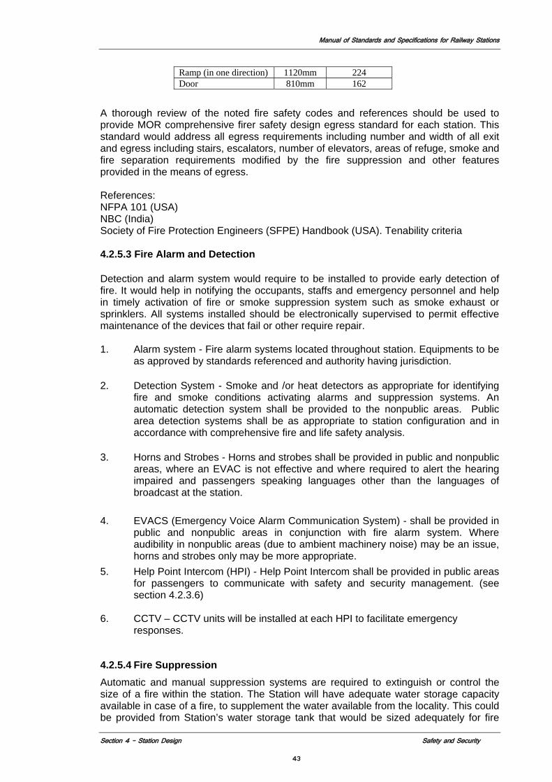
Manual of Standards and Specifications for Railway Stations
Section 4 – Station Design Safety and Security
43
Ramp (in one direction) 1120mm 224 Door 810mm 162
A thorough review of the noted fire safety codes and references should be used to provide MOR comprehensive firer safety design egress standard for each station. This standard would address all egress requirements including number and width of all exit and egress including stairs, escalators, number of elevators, areas of refuge, smoke and fire separation requirements modified by the fire suppression and other features provided in the means of egress. References: NFPA 101 (USA) NBC (India) Society of Fire Protection Engineers (SFPE) Handbook (USA). Tenability criteria 4.2.5.3 Fire Alarm and Detection
Detection and alarm system would require to be installed to provide early detection of fire. It would help in notifying the occupants, staffs and emergency personnel and help in timely activation of fire or smoke suppression system such as smoke exhaust or sprinklers. All systems installed should be electronically supervised to permit effective maintenance of the devices that fail or other require repair.
1. Alarm system - Fire alarm systems located throughout station. Equipments to be
as approved by standards referenced and authority having jurisdiction.
2. Detection System - Smoke and /or heat detectors as appropriate for identifying fire and smoke conditions activating alarms and suppression systems. An automatic detection system shall be provided to the nonpublic areas. Public area detection systems shall be as appropriate to station configuration and in accordance with comprehensive fire and life safety analysis.
3. Horns and Strobes - Horns and strobes shall be provided in public and nonpublic
areas, where an EVAC is not effective and where required to alert the hearing impaired and passengers speaking languages other than the languages of broadcast at the station.
4. EVACS (Emergency Voice Alarm Communication System) - shall be provided in
public and nonpublic areas in conjunction with fire alarm system. Where audibility in nonpublic areas (due to ambient machinery noise) may be an issue, horns and strobes only may be more appropriate.
5. Help Point Intercom (HPI) - Help Point Intercom shall be provided in public areas for passengers to communicate with safety and security management. (see section 4.2.3.6)
6. CCTV – CCTV units will be installed at each HPI to facilitate emergency
responses.
4.2.5.4 Fire Suppression Automatic and manual suppression systems are required to extinguish or control the size of a fire within the station. The Station will have adequate water storage capacity available in case of a fire, to supplement the water available from the locality. This could be provided from Station’s water storage tank that would be sized adequately for fire
Manual of Standards and Specifications for Railway Stations
Section 4 – Station Design Safety and Security
44
suppression requirements of the station or potentially from the reservoir storing the storm and other wastewater collected and treated at the station. 1. Automatic Suppression Systems
Automatic suppression systems would be provided in nonpublic areas with combustible loading. These include • Concession areas • Storage • Trash rooms In public areas automatic suppression systems would be provided in: • Around escalator structure • Enclosed public waiting areas Automatic systems are not to be provided on platform or in open concourse areas. Systems would be provided in accordance with typical suppression systems that are subject to review based upon the overall fire/life safety strategy in compliance with applicable codes. Systems may include but not be limited to dry and wet sprinklers, dry CO2 etc.
2. Standpipe System
Standpipe systems are to be provided through out stations in accordance with typical suppression systems that are subject to review based upon the overall fire/life safety strategy in compliance with applicable codes.
3. Portable Firefighting Equipment
Fire extinguishers shall be provided in areas in accordance with MOR approved strategy and review of the overall fire/life safety policy. There are four extinguisher types of units for fighting different types of fires that may occur in a rail transit environment. They are: Extinguisher type
Water Solid waste fires Power Liquid and electrical fires Foam Liquid fires Co2 Liquid and electrical fires
Reference: NBC (India) International Building Code (IBC) NFPA 72 (USA) NFPA 14 (USA) NFPA 10 (USA) 4.2.5.5 Control of Fire Spread (Compartmentation) Stations shall be constructed to prevent a fire from spreading from its origin to other areas or compartments of the station. 1. Separation
Fire separations shall be determined based upon the overall fire/life safety strategy in compliance with applicable codes. Following is a sample list of requirements: • Transit and non transit Occupancies 3 hours • Public and non public 2 hours • Train control and electrical rooms from all other
occupancies 2 hours
Manual of Standards and Specifications for Railway Stations
Section 4 – Station Design Safety and Security
45
• Power substations form all other occupancies 3 hours 2. Openings
All openings in fire rated walls shall be rated and as appropriate to maintain the fire rating of the wall. Doors in major fire separations between public areas shall be automatic self closing type with required activation.
3. Penetrations
All penetrations in rated walls shall be fire stopped and be provided by with fire and or smoke dampers. Typical locations include: • Duct penetrations of rated corridors • Penetrations through occupancy separations, and area separation walls • Smoke barriers • Shafts serving multiple levels
References: NFPA 130 (USA) NBC (India) 4.2.5.6 Structural Protection 1. Station structural fire protection shall be provided in accordance with design
requirements to prevent collapse of part or all of the structure due to fire. Construction shall according to the National Building Codes requirements unless performance-based methods are used to verify that adequate structural protection is being provided.
2. Attached or shared Station complex Structures
In the event that the station structure shares any portion of its structure with a non transit building, the entire structure of that building shall be designed to the fire safety classification of the station structure or higher.
References: NBC (India) NFPA 130 (USA) International building Code (IBC)
4.2.6 Station Elements
4.2.6.1 Platforms
Platform fire safety requirements reflect the need to use all available means of access as part of the evacuation resources. A combination of the following techniques requires consideration for egress from platforms: 1. Egress capacity shall be designed for peak operation as determined in section
4.5.3.
2. Capacity of egress elements shall be designed to provide adequate clear widths on staircases, escalators, passages, and maximum travel distances to egress during tenable conditions shall be in accordance with NFPA 130 (Annex C) and NFPA 101 (Chapters 7 and 12) and in no case shall dimensions for egress elements be less than those noted in 4.2.5.2
Egress calculations shall include escalators as part of evacuation capacity but
they shall not account for more than 50% of the exit capacity, and assume that on any platform one escalator will be out of service during an emergency
Manual of Standards and Specifications for Railway Stations
Section 4 – Station Design Safety and Security
46
evacuation. In no case should the distance on a platform to a vertical means of egress be more than 91.4m.
3. Maintenance of tenable conditions for the time required for evacuation. Reference: NFPA 130 (USA) NFPA 101 (USA) Society of Fire Protection Engineers (SFPE) Handbook (USA)
4.2.6.2 Ancillary Areas
Fire safety requirements for ancillary non public spaces shall be as called for in their respective area of operation by the overall analysis of the stations fire and life safety requirements in compliance with applicable codes and standards.
Reference NBC (India) NFPA 251 (USA)
4.2.6.3 Adjoining Premises
All egress should assume exit to the outside on public or MOR property. Adjoining properties or structures shall be considered as fire safety barriers that the station fire safety design will work around. In no case shall they be considered as viable means of egress. Existing or created station separations within a station will require: 1. Independent egress capacity based on individual station 2. Communication channels between station operators during an emergency are to
be established.
4.2.6.4 Mobility Impaired
Areas of refuge will be required on each level that the mobility impaired have access to. They shall be as follows:
1. Areas of refuge for the mobility impaired shall conform to the maximum travel
distance of 91.4m and are to be provided within the protected emergency egress staircase enclosure that permits supervised evacuation.
2. Two-way communication systems by means of help-point intercom (HPI) in
refuge areas.
3. Additional equipment such as evacuation chairs, to be provided to assist emergency personnel.
4. Tactile Braille signage complying with Handicap requirements shall be located at
each door to an area of refuge
References: Section 4.3. NFPA 130 NFPA 101
Manual of Standards and Specifications for Railway Stations
Section 4 – Station Design Safety and Security
47
4.2.6.5 Concessions
For the purpose of establishing fire safety requirements Concessions shall be classified as follows:
1. Small concession kiosk is considered as open space, and treated as a piece of
furniture or equipment in the public areas. It will be deemed to have no fire safety characteristics except for the structure of the kiosk which would be incombustible.
2. Separated concession space with down stands sometimes referred to as a
“cabin.” This is a separated space built of incombustible material with no fire ratings for the enclosure but with self contained suppression and control system.
3. Enclosed concession space that it is part of the overall station design and will
conform to all of the requirements of the station fire safety design.
Classification is based on size and use. Small concessions are generally portable and occupy less than 3 square m. Separated space with rolled down closure stands is generally applied to a fixed concession in the center of a platform/ Fire rated enclosures are generally required where the concession is a large area along the wall, adjacent to other ancillary rooms within the station requiring fire separation. Concession areas could be designed using concepts of compartmentation, separation and limitation of fire loads or localized extract.
References: NFPA 101 (USA) NBC (India)
4.2.7 Management and Maintenance
The maintenance and testing of the station fire safety systems is a key factor in maintaining the tenability of the emergency capabilities of the station. Heavily used public facilities such as train station require that an effective maintenance program to be developed and implemented to assure viability of equipment and controls. In conjunction with the maintenance an ongoing training program also must be in place that keeps key station staff current on the management of the various systems that make up the on the fire and life safety protection for the station.
4.2.7.1 Design All electronic safety and security systems must be designed with provisions to facilitate maintenance of the systems. This requires that they have supervisory wiring and adequate monitoring and control. This ensures that every device can be individually tracked to determined status of operation and available power. In addition in the event that a device fails it should not affect the remainder of the system and repairs and or replacement can be effected expeditiously. 4.2.7.2 Maintenance
Protocols for the cleaning, repairs and replacement need to be established. It should ensure, adequacy of stock for all fire and life safety systems, detailed regular reporting on conditions of critical systems and identification of staff and outside vendor resources required to keep system in an acceptable state of repair. Automated maintenance
Manual of Standards and Specifications for Railway Stations
Section 4 – Station Design Safety and Security
48
monitoring systems that are part of overall station maintenance should incorporate these requirements.
1. Management
The management of the station should have a distinct program that addresses security and fire and life safety. There should be dedicated staff to oversee this operation that will ensure that: a. Extensive testing and monitoring and certification protocols for all equipment and
systems are established b. All staff is adequately trained for the operation and assessment of this equipment
and procedures c. Emergency preparedness plans are developed and maintained and that all
appropriate staff is properly informed and hierarchy of responsibility is clearly defined in an emergency.
d. Adequate communication channels are maintained with other MOR facilities and the local security and fire safety agencies that can respond in the event of an emergency.
2. Training Fire and life safety systems like all technically complex installations for this type of facility require trained personnel to operate. Just as the management of the trains requires specially trained staff that receives training refreshers to deal with changes in the system and or changes in technology. Initial training should be provided as part of the system installation costs and subsequent training should tie in to ongoing contracts to the vendors maintaining the equipment and systems for the station. The station management should make provision to include the cost of this training as part of their operating expenses.
Manual of Standards and Specifications for Railway Stations
Section 4 – Station Design Handicap Accessibility
49
4.3 HANDICAP ACCESSIBILITY
4.3.1 Introduction Handicap Accessibility at Indian Railway Stations is essential, as it facilitates access for elderly and physically challenged transit customers and employees. Indian Railways is committed to providing a barrier free environment which provides a high level of customer service especially to the elderly, mobility impaired, and disabled.
Codes and Standards The latest editions of the following reference standards, regulations and codes will be utilized: Indian Disability Act 1995 Guidelines and space standards for Barrier free built Environment or Disabled
and Elderly persons – 1998, C.P.W.D. Ministry of Urban Affairs and Employment, India.
ADA Accessibility Guidelines for Buildings and Facilities (ADAAG), 1998 National Building Code International Building Code (IBC).
Note: ADA Accessibility Guidelines for Buildings and Facilities (ADAAG), shall be the controlling code, where it is silent the NBC will apply. Manual of Standards and Specifications for Railway Stations relevant sections • Planning and Design Principles • Safety and Security • Station Layout and Circulation • Materials and Finishes • Lighting • Signage and Graphics • Furniture Fixtures, and Equipment
4.3.2 Requirements and Recommendations All Railway Stations must be fully accessible as per the requirements of the Indian Disability Act 1995 and guidelines for CPWD. ADAAG (Americans with Disabilities Act Accessibility Guidelines) is a prescriptive standard that details specific measures for compliance with handicap accessibility needs and will serve as a minimum requirement, as listed below. Design of these stations must comply with ADAAG 10 (transportation facilities). The facilities and installations that are provided in the station, must comply with above codes. General principle is to provide facilities for the: 1. Visually impaired 2. Audibly impaired 3. Physically disabled
4.3.2.1 Accessible Entrance At every intermodal connection and every street access, there should be at least one handicap access entrance, specific location to be called for in Concessionaire’s agreement and its attachments. Dedicated drop-off and pick-up points are to be
Manual of Standards and Specifications for Railway Stations
Section 4 – Station Design Handicap Accessibility
50
provided for wheelchair-bound passengers. The approach should not have a difference in level. If a level difference is unavoidable, install a ramp or a ramp with staircase. All the approaches to the station shall be paved surfaces. It is desirable that space be clearly demarcated near the entrance / exits for vehicles carrying wheelchair users. Location(s) of additional accessible entrances, if any, will be determined based on best passenger service, station design/configuration, and site constraints. Braille and tactile layout plans are to be located at designated station entrances. Refer these relevant codes 1. ADAAG/4.13-4.14 2. NBC/D 2.2, D 3.2
4.3.2.2 Elevators One elevator required per accessible entrance which shall be designed to ADAAG 4.10 and 10.3.1(17). Wherever possible provide at least two elevators along the accessible path between different levels to ensure redundancy. Install two guiding blocks for persons with impaired vision 300 mm away from the call button. The space should be indicated inside and outside the car using the universally recognized symbol for wheelchair accessibility. Install a ring strap or other appropriate safety grip for wheelchair users to hold onto. Floor indicators on the elevator exteriors shall have tactile/Braille signage. (Refer chapter 4.9.5.13). Actual/preferred location of elevators will be determined on a station-specific basis. Elevator cabs will be sized to accommodate gurney (portable wheeled carrying cot for incapacitated person).
4.3.2.3 Escalators Design to ADAAG 10.3.1(16). All escalators are to be fitted with audible indicators to warn the visually impaired passengers that the escalator is running in the conflicting direction.
4.3.2.4 Connections to Existing Facilities All direct connections to existing transit facilities (platforms/other modes of transportation) are required to be accessible as per ADAAG 4.3 and 10.3.1(3). Tactile hazard markings shall be provided at danger areas such as escalator landings, stairwells, and passenger lift accesses. Any obstructions such as freestanding signs, telephone enclosures, or fire hose cabinets shall be cane detectable and protected, either by horizontal bars set 100mm above floor level, or by a wing wall around the obstructions. All direct connections to commercial, parking lots, bus bays, retail facilities shall have an accessible route from the point of connection to all boarding platforms (ADAAG 4.3). All existing station facilities located along an accessible route or circulation path connecting an existing station to or from the renovated/expanded part of the station must be made handicap regulation compliant as per the Indian Disability Act 1995 / ADAAG requirements for rehabilitation of existing stations (ADAAG 10.3.2 and 3, and 4.1.6 / Equivalent Indian Standards). Design of new infrastructure for accessible transfer routes must be governed by all applicable IDA, and NBC requirements for new stations and ADAAG 10.3 or equivalent Indian standards. Parking lot design for handicap should comply with ADAAG 4.6
4.3.2.5 Accessible Route Design to ADAAG 4.3 and 10.3.1(1) or equivalent Indian standards.
Manual of Standards and Specifications for Railway Stations
Section 4 – Station Design Handicap Accessibility
51
Floor surfaces/slopes; maximum slope in any direction not to exceed 1:48. Refer code (NBC/D 3.6); Ramps to meet ADAAG 4.8 or equivalent Indian standards; Refer code (NBC/D 3.1) 4.3.2.6 Accessible Means of Egress/Area of Rescue Assistance (Area of Refuge) Design to ADAAG 4.3.10 and 11 or equivalent Indian standards for area of rescue assistance or area of refuge.
4.3.2.7 Stairs
Design to ADAAG 4.9 and 4.26 / Equivalent Indian Standards. Tactile warning strip shall be provided at the first and last step. Refer code (NBC/D 3.5)
4.3.2.8 Control Gates At least one of the control gates in every entrance area should be wide enough to allow wheelchair users to pass through easily and have a continuous line of guiding blocks for persons with impaired vision. 4.3.2. 9 Ticket Booths/ Ticket Vending Machines Comply with ADAAG 10.3.1(7), 4.2.4.1, 4.2.5 and 4.3.4.1 through 4. At least on ticket booth in each group of booths should be at a suitable height for easy access by wheelchair users. A knee recess beneath the ticket vending machines should be provided. Install guiding blocks for persons with impaired vision 300 mm away from the ticket vending machine. The fare buttons and other information buttons should be written in Braille or in a distinct relief pattern. Tactile guide paths are to be provided to lead the visually impaired passengers from the designated entrances, to the ticket office, ticket vending machines and the control gates and then to the passenger lift. Induction loops are to be provided for passengers with hearing impairment (For Details: - TCRP Report12, Ch 8, Page 39). 4.3.2. 10Station Information Centre Unmanned station information centre would have information on route, local area access and station map. Counter height should not be in excess of .85 m. See section 4.9.
4.3.2.11 Public Address (PA) PA shall be in accordance with ADAAG requirements. See section 4.11.6.7 4.3.2.12 Public Pay Telephones Provide text telephones on each level in the stations. Refer code (NBC/D 3.9). 4.3.2.13 Toilets Handicap accessible public toilets will be provided in all public areas. The toilets shall be accessible without passing through other toilet spaces. Toilet rooms for persons with special needs shall be provided with an alarm linked to an outside light and to the Station Control Room, station staff will assist when requested. Refer code (ADAAG /4.17-4.19 and NBC/D 3.7) 4.3.2.14 Concessions and Commercial Areas All concession and commercial areas will be handicap accessible. Refer code (ADAAG /5.0-7.0)
Manual of Standards and Specifications for Railway Stations
Section 4 – Station Design Handicap Accessibility
52
4.3.2.15 Detectable Warning Install platform edge detectable warning systems. Refer code (ADAAG /4.28-4.29 and NBC/D 3.14). Appropriate visible messages shall be provided at all station public areas. Passenger Information Displays to provide service and emergency information are to be located at high level in the Concourses and Platforms. 4.3.2.16 Clocks Refer to FF&E section (Section 4.11.5.1).
4.3.3 Signage
Refer code (ADAAG /4.30) and Section 4.9. Accessible entries and paths will be identified by in accordance with the international symbol of accessibility (ISA). Specific requirements are as follows: 1. Accessible entrances must be identified with the ISA symbols. 2. Non-accessible entrances shall have way finding sign indicating the location of
the nearest accessible entrance. 3. ISA symbols must be placed on elevator shafts at all levels. 4. Accessible self-service fare collection gates (AFAS) must be identified with the
ISA symbols mounted 1524mm above the finish floor to the centerline of signs on both sides of the service gate.
5. Wayfinding signs indicating the locations of elevators, ramps and other accessible facilities must be placed at all decision points within a station.
6. Signage indicating the location of the nearest text telephone (TTY) must be provided at all non-TTY phones. Provide Braille signs or new technology equivalent at all exits.
4.3.4 Lighting
Refer to Lighting section (Section 4.7). 4.3.4.1 Concourse The width of the concourse should be at least 1800 mm. The concourse should not have a level difference. If a level difference is unavoidable, install a ramp (Ramps to meet ADAAG 4.8) or a ramp plus staircase. The floor surface of the concourse should be made of non slip material (must comply with ADAAG 4.5). At places where the difference in level such as stairs, it is desirable that the appearance of the surface material be changed using colour contrast. Ensure that the columns, signboards and other fixtures do not protrude from wall surfaces. Install guiding blocks on the concourse for person with impaired vision. 4.3.4.2 Platforms The platform should have one row of dotted guiding blocks for persons with impaired vision, 800 mm or more from the edge. The paved surface of the platform must be made with a non slip material (must comply with ADAAG 4.5). Stairs, kiosks and dustbins on the platform must not hinder the clear passage of persons with impaired vision and wheelchair users. A bench should be installed on the platform, having guiding block around it. An appropriate numbers (Refer ADAAG 4.32) of designated seats for passengers with disabilities and for elderly people should be provided near the doors.
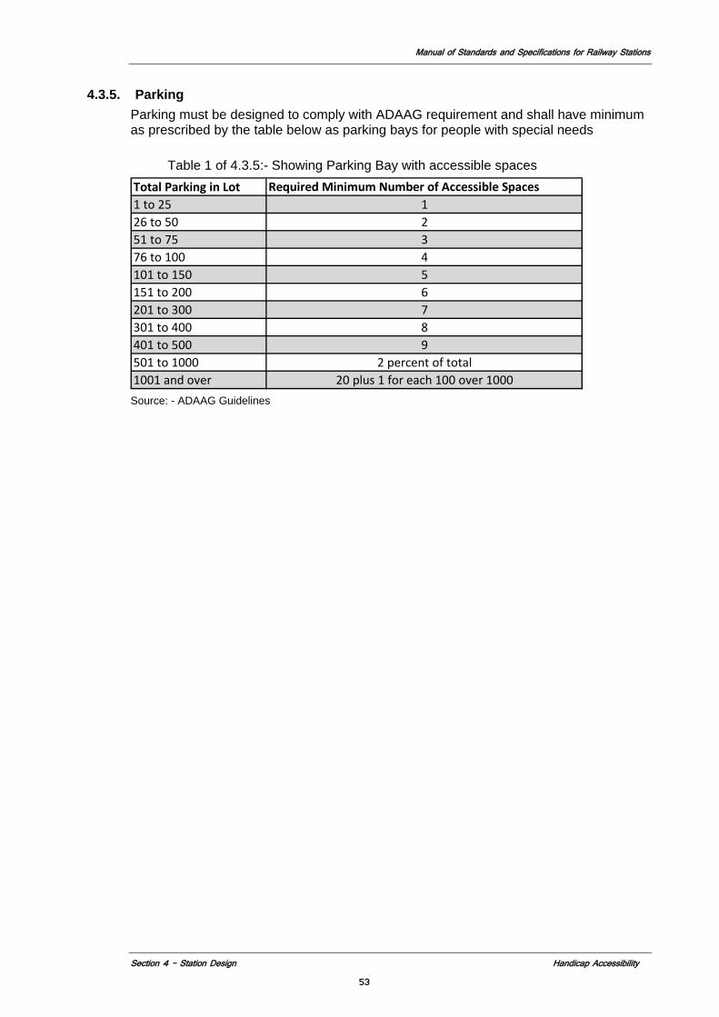
Manual of Standards and Specifications for Railway Stations
Section 4 – Station Design Handicap Accessibility
53
4.3.5. Parking Parking must be designed to comply with ADAAG requirement and shall have minimum as prescribed by the table below as parking bays for people with special needs Table 1 of 4.3.5:- Showing Parking Bay with accessible spaces Total Parking in Lot Required Minimum Number of Accessible Spaces1 to 25 126 to 50 251 to 75 376 to 100 4101 to 150 5151 to 200 6201 to 300 7301 to 400 8401 to 500 9501 to 1000 2 percent of total1001 and over 20 plus 1 for each 100 over 1000 Source: - ADAAG Guidelines
Manual of Standards and Specifications for Railway Station
Section 4 – Station Design Modular Elements Approach
54
4.4 MODULAR ELEMENTS APPROACH
4.4.1 Introduction There are two aspects to Modular Elements that will be addressed in this section. The first is the requirement that similar elements at the station be designed in a consistent manner to enhance wayfinding and visual clarity and order to the stations spatial orientation. The second is to consider what elements should be consistent throughout the system, while designing the new stations. This would facilitate the passengers to have a clear and consistent visual identity throughout the system. This would in turn help in creating a level of comfort and familiarity to passengers using the system. Thus it would give a brand recognition to the MoR. Apart from gaining recognition, modularized elements would prove to be cost efficient to MoR as the maintenance, repair and replacement can be done with an economy of scale. It could also enhance the value of station revenue producing features such as advertising that could be considered on a national basis not just for one station.
4.4.2 Station Recommendations
Elements of continuity are essential in establishing the character and identity of new stations. Prototypical visual elements of continuity within the existing system can be transformed to give new stations character of their own time, yet firmly locate them as part of the Indian Railway Station System. 4.4.2.1 Access 1. All station entrances aside from main entrance 2. All Control Gates 3. All service doors in public areas 4. All visible utility access panels and or systems 4.4.2.2 Circulation 1. Stairs and escalators. 2. Elevator type, size, materials, location, and orientation.
4.4.2.3 Wall/Floor/Ceiling Modules in public Areas Floors, walls and ceilings shall utilize a modular grid to organize materials, finishes, and other architectural elements and ensure consistency of the architectural design throughout station.
4.4.2.4 Lighting Lighting shall be standardized with respect to lamp, type (direct/indirect/task), level, source, and location.
4.4.2.5 Advertising Elements of advertising shall be standardized in size, type, mounting details and methods, and location throughout a station. (Example: on specific wall where
Manual of Standards and Specifications for Railway Station
Section 4 – Station Design Modular Elements Approach
55
advertising is permitted there should be only one type and size of advertising permitted so as not to create visual pollution). The advertising module must be coordinated with other modular elements in the station, including signage, structure, control and construction joints and finishes. Advertising panels should complement the architecture of the station. 4.4.2.6 Architectural Details The design of several architectural details shall be standardized. These include: 1. Platform edge 2. Stairs for Public and Nonpublic Area, including emergency egress stairs 3. Escalators: cladding, details, and materials 4. Guardrails/ parapets around stairs/ escalators/ elevators and other openings;
material details 5. Passenger Control Barriers; materials, design, and detailing 6. Doors / windows / ventilators/ other openings and Hardware: type, size,
material, finish and color in public areas 7. Platform-End Emergency Gates: location, design, details and materials 8. Flooring / walling / ceiling : Material, graphics and pattern e.g. type of spaces
4.4.2.7 Station Furniture and facilities The architect shall develop or specify standards and designs specifying the material, colour, robustness for seating, tables, counters newspaper vending machine, recycling and trash receptacles, information board, information booth, and other station furniture and fixtures. The furniture for each area of the station should be consistent. Following is sample list: 1. Toilets 2. Lounges and Cafes 3. Concession stands for retail and food 4. Vending machines 5. Waiting room furniture (reserved/unreserved) 6. Lounge furniture 7. Platform furniture 8. Ticket/inquiry booths 9. TVM’s 10. Trash receptacles 11. Counters 12. Public telephone 13. ATM’s 14. Station Information Centers 15. Public Security Stations 4.4.2.8 Variable Elements Variable Elements should respond to and reflect local or special context by introducing variations in design and finishes that reinforce unique locations. Following is a sample list: 1. Main station entrance 2. Intermodal access/egress points
Manual of Standards and Specifications for Railway Station
Section 4 – Station Design Modular Elements Approach
56
3. Landscaping around station 4.4.2.9 Architectural finishes There should be consistent use of similar finishes for like type spaces (i.e. waiting areas, entrance areas, platforms etc.). Finishes in public areas may be elements of variability within a range of approved materials. 4.4.2.10 Color There should be consistent use of similar colors for like type spaces (i.e. waiting areas, entrance areas, platforms etc.). Colors for architectural finishes shall be consistent and/or complimentary with those used in existing stations and previously approved by Indian Railways. 4.4.2.11 Communications: Standard design; placement, mounting/attachment details and typical finishes. 1. Help-Point Intercom (HPI) 2. Public Address Devices 3. Customer Information displays 4. Station Information Centre (SIC) 5. CCTV Cameras 6. Public telephones
4.4.3 System Recommendations Elements of station design that have potential for system wide application.
4.4.3.1 Access 1. Control Gates 4.4.3.2 Lighting Lighting shall be standardized with respect to lamp, type (direct/indirect/task), level, source, and location. 4.4.3.3 Advertising Elements of advertising shall be standardized in size, type, mounting details and methods, and location throughout all stations. 4.4.3.4 Station Furniture and facilities 1. Toilets 2. Lounges and Cafes 3. Concession stands for retail and food 4. Vending machines 5. Waiting room furniture (reserved/unreserved)
Manual of Standards and Specifications for Railway Station
Section 4 – Station Design Modular Elements Approach
57
6. Lounge furniture 7. Platform furniture 8. Ticket/Inquiry booths 9. TVM’s 10. Trash receptacles 11. Counters 12. Public telephone 13. ATM’s 14. Station Information Centers 15. Public telephone 16. Public Security Stations
4.4.3.5 Communications: 1. Help-Point Intercom (HPI) 2. Public Address 3. Customer Information displays 4. Station Information Centre (SIC) 5. CCTV Cameras 6. Public telephones
4.4.4 Sustainability Strategies
The development of system-wide elements shall demonstrate Indian Railways commitment to sustainable practices. Develop system-wide elements to support and encourage sustainable behavior. Source products and material locally and ensure they have a low embodied energy and high recycled material content. Suggested strategies are shown below. 1. Specify products with recycled content 2. Specify local/regional material and equipment 3. Specify low maintenance materials
Manual of Standards and Specifications for Railway Stations
Section 4 – Station Design Station Layout and Circulation 58
4.5 STATION LAYOUTS AND CIRCULATION
4.5.1 Introduction
Station configuration addresses the geometry and functional needs of the station design. Station configuration issues involve the design of station entrances, the arrangement of the train platform(s), the location and relationship of the fare control area(s) to the entrance(s) and platform(s), parking facilities, work and rest areas, and the integration of ancillary and support facilities with the public functions. Station designers are required to adopt a guiding set of principles that establish the design priorities for the project. These guiding principles should be clearly expressed and easily communicated such that the most important aspects of the design can be defended and protected against future encumbrances. The design of new stations should acknowledge the hierarchy of elements contributing to the whole. Designers may consider that these elements fall generally into primary, secondary and tertiary orders, each with their own design considerations. References INDIAN RAILWAYS Design Manuals/Policy Instructions and codes Section 1.11 NFPA 130 (USA) NBC (India) IBC (International Building Code).
4.5.2 Goals and Objectives 4.5.2.1 Customer Safety and Security 1. Safety and Health - Design to minimize the possibility of accidents and health
hazards. Strategies shall include, but shall not be limited to the following: a) Adequate and appropriate lighting b) Slip-resistant walking surfaces c) Appropriate use of guards and safety rails d) Minimization of tripping hazards e) Correct application of materials and methods of construction.
2. Security - Stations shall be designed to be safe and secure without depending
on technology and equipment. Strategies shall include, but shall not be limited to the following:
(i) Providing public areas that are well lit and designed to maximize visibility a) Providing a direct and clearly defined pedestrian route of travel b) Provide safe travel for the physically challenged people c) Maximizing accessibility while providing the maximum degree of
security from crime, attack and unauthorized entry d) Encouraging territoriality, natural surveillance, activity support,
and access control Refer to the Sections on Safety and Security (4.2), Sustainable Development and Environmental Considerations (5.2). 4.5.2.2 Efficient Movement of Customers Strategies to facilitate the free flow of passengers shall include, but shall not be limited to the following:
Manual of Standards and Specifications for Railway Stations
Section 4 – Station Design Station Layout and Circulation 59
1. Separation of different categories of passengers. 2. Design of a clear, simple, and direct passenger circulation system,
minimizing turns and decision points 3. Minimizing travel distances 4. Efficient and strategic use of VCEs 5. Efficient and strategic use of electronic boards to display information
about train schedules, etc. 6. Minimizing cross-flows and conflicting passenger movements 4.5.2.3 Customer Satisfaction, Comfort, and Convenience The designer shall focus on customer service including, but not limited to the following: 1. Minimizing travel distance between the station entrance and the train 2. Providing assisted locomotion (i.e., elevators, escalators, moving
walkways, equipment for the physically challenged, e.g., wheel chairs) 3. Providing a clear and logical customer circulation system 4. Minimizing turns in the path of travel 5. Avoiding obstructions to customer movement 6. Minimizing pedestrian conflicts and cross-flows 7. Providing adequate customer amenities to accommodate customer
needs 8. Providing an acceptable Level of Service (minimum LOS C) to ensure a
minimum degree of passenger comfort 9. Information 10. Ticketing service 11. Passenger waiting areas 12. Passenger toilet facilities (men/women/handicapped) 13. Stores, shops, food stalls/restaurants 14. Providing potable water at the platforms, in addition to the station facility 15. Providing a comfortable environment with respect to acoustic, thermal,
lighting and air quality 4.5.2.4 Quality Design 1. Economy, Efficiency, and Effectiveness The station designer shall:
a) Integrate systems (structure, space, materials, lighting, communications, and mechanical);
b) Provide innovative design solutions; c) Maximize value, employ value management strategies; d) Employ sustainable design principles.
2. Spatial, Architectural, and Organizational Characteristics To design the station to reflect the design manuals and the organization of the customer circulation network, the station designer shall:
a) Provide an open, spacious design; eliminate columns (where possible) and obstructions; create clear space for passenger circulation;
b) Integrate structure and architectural finishes; c) Introduce daylight to the station interior; d) Provide visual/aesthetic consistency with the larger system while
reflecting site-specific characteristics. See Section 4.4 Modular Elements Approach.
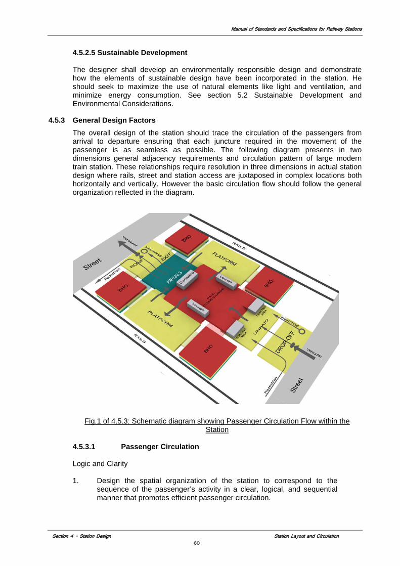
Manual of Standards and Specifications for Railway Stations
Section 4 – Station Design Station Layout and Circulation 60
4.5.2.5 Sustainable Development The designer shall develop an environmentally responsible design and demonstrate how the elements of sustainable design have been incorporated in the station. He should seek to maximize the use of natural elements like light and ventilation, and minimize energy consumption. See section 5.2 Sustainable Development and Environmental Considerations.
4.5.3 General Design Factors The overall design of the station should trace the circulation of the passengers from arrival to departure ensuring that each juncture required in the movement of the passenger is as seamless as possible. The following diagram presents in two dimensions general adjacency requirements and circulation pattern of large modern train station. These relationships require resolution in three dimensions in actual station design where rails, street and station access are juxtaposed in complex locations both horizontally and vertically. However the basic circulation flow should follow the general organization reflected in the diagram.
Fig.1 of 4.5.3: Schematic diagram showing Passenger Circulation Flow within the Station
4.5.3.1 Passenger Circulation Logic and Clarity 1. Design the spatial organization of the station to correspond to the
sequence of the passenger’s activity in a clear, logical, and sequential manner that promotes efficient passenger circulation.
Manual of Standards and Specifications for Railway Stations
Section 4 – Station Design Station Layout and Circulation 61
2. Separate arriving and departing passengers horizontally and/or vertically based on extent of passenger movement and size and location of spaces required.
3. Separate commuting and long distance passengers. 4. Avoid unnecessary turns in the circulation path. 5. Passenger Orientation and Decision Making 6. Minimize customer decisions along the path of circulation. 7. Where necessary, provide consistent and clear directional signage. Boarding and Alighting the Train Coach (pass through stations) 1. Define the train doors in relation to the platform and encourage embarking
passengers to stand clear using contrasting floor finishes and signage. 2. Provide sufficient unobstructed space for embarking and disembarking
passengers to queue and pass on their way to and from the Train Coach. 4.5.3.2 Passenger Profile Indian railways cater to a very large volume of passengers belonging to all sections of the society. It has become a lifeline of big cities like Mumbai, Kolkata, and Chennai dealing with huge commuter traffic. Hence, it deals in a varied profile of the passengers. One demarcation that stands out is that of Commuter traffic and Long Distance travelers. The commuter travelers outnumber the Long Distance travelers by a large margin in these cities. The station platforms dealing with commuter trains should be segregated from the Long Distance platforms as they deal in passengers that require different level of service. In order to transfer passengers efficiently from the street level to train and vice versa, station planning must be based on established principles of pedestrian flow and arranged to minimize unnecessary walking distance and cross flows between incoming and outgoing passengers. 4.5.3.3 Level of Service (LOS) Performance Standard LOS performance standards provide a method of sizing passenger circulation elements that respond to the demands of pedestrian behavior based on John J. Fruin’s Pedestrian Planning and Design (1987). The capacity of passenger circulation elements shall permit natural, free-speed passenger movement and consider the physical dimensions of the human body and human locomotion. A LOS of C or greater shall be used for all passenger circulation elements based on the projected passenger/ridership load target specified in the Concession Agreement or as called for in section 2.4 Basis of Design. However, station design shall take into account seasonal peak use and ensure that all station components conform to a Level of Service (LOS) D during this period. The following charts outline the LOS requirements of various station elements. In design of certain facilities, where J.J Fruin standards are not applicable International Aviation Transportation Association (IATA) standards shall apply.
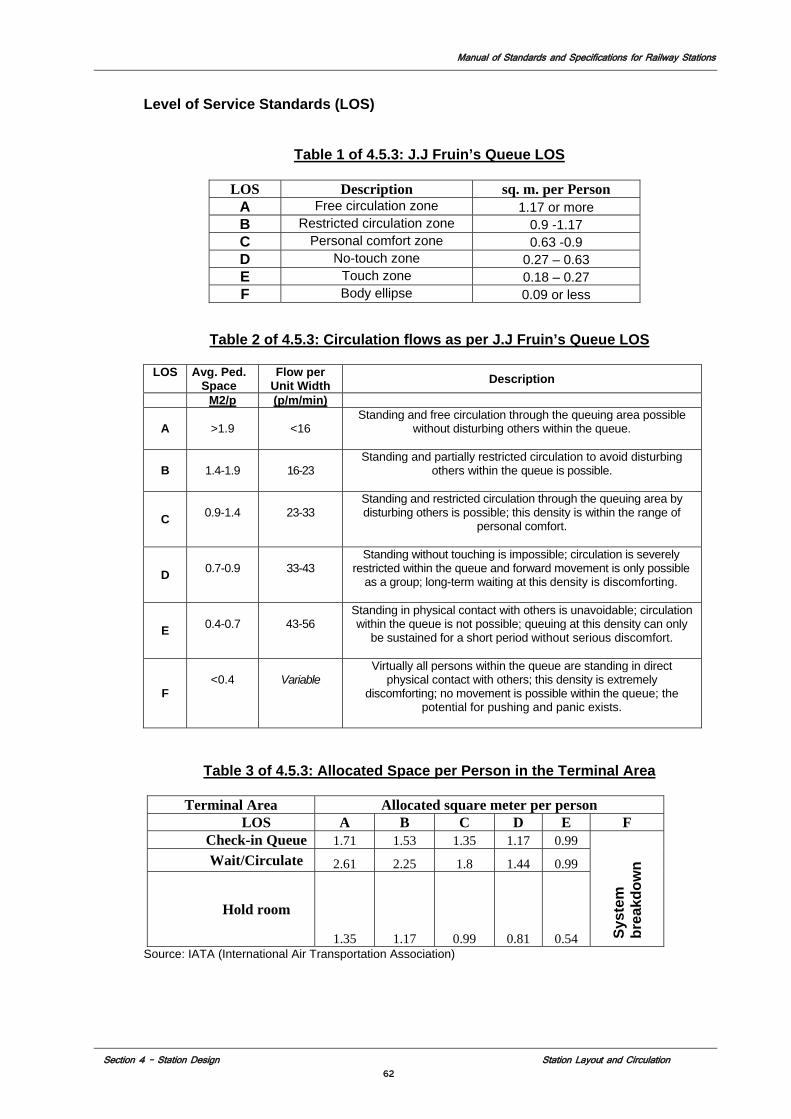
Manual of Standards and Specifications for Railway Stations
Section 4 – Station Design Station Layout and Circulation 62
Level of Service Standards (LOS)
Table 1 of 4.5.3: J.J Fruin’s Queue LOS
Table 2 of 4.5.3: Circulation flows as per J.J Fruin’s Queue LOS
LOS Avg. Ped.
Space Flow per
Unit Width Description
M2/p (p/m/min)
A
>1.9
<16
Standing and free circulation through the queuing area possible without disturbing others within the queue.
B
1.4-1.9
16-23
Standing and partially restricted circulation to avoid disturbing others within the queue is possible.
C
0.9-1.4
23-33
Standing and restricted circulation through the queuing area by disturbing others is possible; this density is within the range of
personal comfort.
D
0.7-0.9
33-43
Standing without touching is impossible; circulation is severely restricted within the queue and forward movement is only possible
as a group; long-term waiting at this density is discomforting.
E
0.4-0.7
43-56
Standing in physical contact with others is unavoidable; circulation within the queue is not possible; queuing at this density can only
be sustained for a short period without serious discomfort.
F
<0.4
Variable
Virtually all persons within the queue are standing in direct physical contact with others; this density is extremely
discomforting; no movement is possible within the queue; the potential for pushing and panic exists.
Table 3 of 4.5.3: Allocated Space per Person in the Terminal Area
Terminal Area Allocated square meter per person LOS A B C D E F
Check-in Queue 1.71 1.53 1.35 1.17 0.99
Syst
em
brea
kdow
n Wait/Circulate 2.61 2.25 1.8 1.44 0.99
Hold room
1.35 1.17 0.99 0.81 0.54 Source: IATA (International Air Transportation Association)
LOS Description sq. m. per Person A Free circulation zone 1.17 or more B Restricted circulation zone 0.9 -1.17 C Personal comfort zone 0.63 -0.9 D No-touch zone 0.27 – 0.63 E Touch zone 0.18 – 0.27 F Body ellipse 0.09 or less
Manual of Standards and Specifications for Railway Stations
Section 4 – Station Design Station Layout and Circulation 63
4.5.3.4 Determining Capacity Capacity for the various station elements shall be based on a percentage of the maximum practical capacity depending on the location and usage. However, station design shall take into account seasonal peak use and ensure that all station components conform to a Level of Service (LOS) D during that period. The station designer will would prepare a capacity analysis that identifies all the station elements and their respective operational and safety evacuation requirements and notes how the above referenced LOS C is achieved. The analysis will be based on the following types of factors: 1. Overall station – Design year horizon average peak day. 2. Concourses – Based on analysis of maximum number of trains alighting and
detraining at peak operation (may vary depending on extent of transfer activity). 3. Circulation elements - The maximum throughput established for each passenger
circulation element (The emergency egress requirements of the station as determined by the requirements of NFPA 130 and 101).
4. Entrance/Egress – Peak hourly load as determined by analysis (minimum of 10% of average peak daily capacity).
5. Platforms – Peak train discharge as determined by analysis (min-center platform two full capacity trains discharging simultaneously, min-side platform one full capacity train discharging).
6. Amenities - Based on analysis of maximum number of trains alighting and detraining at peak operation (may vary depending on extent of transfer activity) and passenger profile.
7. Service standards – Any requirement established to clear the platform of arriving passengers within a given length of time after the train arrives for performance, operational, or other reasons
The key elements of the station’s normal passenger circulation system (excluding emergency egress) are: • VCEs • Platforms • Control Gates • Passageways • Ticketing • Entrances/Exits • Arrival and Departure Concourses A sample calculation for capacity is provided at selected components 4.5.3.5 Station Type 1. Line Stations
Line stations lie between the terminal ends of the tracks and do not connect (provide transfers) to any other stations. Line stations serve origin and destination passengers only (i.e., all customers enter the station from a station entrance or from a train). Line stations predominantly serve passengers destined to or bound from the station’s immediate catchments area. Passenger flows at line stations tend to be bi-directional, depending on demand characteristics. Design considerations may include:
a) Accommodation of peak passenger movements b) Accommodation of staff facilities
Manual of Standards and Specifications for Railway Stations
Section 4 – Station Design Station Layout and Circulation 64
2. Terminal Stations
Terminal stations are located at the end of the Railway line network and tend to have significant inter-modal transfers. Terminal stations tend to serve passengers from beyond the immediate station catchment area. Commuter Passenger flows at terminal stations tend to be unidirectional according to morning and evening peak passenger demands. In case of Long Distance trains at the Terminal Station, the Passenger flow is equally spread over the day. Design considerations shall include among others: a) Accommodation of large peak passenger movements associated
with terminating trains b) Inter-modal transfer to transit and non-transit modes (e.g., bus,
auto) c) Park-and-ride, kiss-and-ride facilities d) Accommodation of storage tracks and maintenance facilities e) Accommodation of staff facilities
3. Transfer Stations
Transfer stations connect different railway lines and stations and are subject to large transfer passenger flows. Transfer connections are typically made via passageways and VCEs connecting other areas of the station and platforms. Passenger transfers should be made within the paid areas of stations. Design considerations may include the following: a) Utilizing moving walkways to assist customers and reduce travel time
over long (> 153 m) distances b) Providing an accessible transfer between station platforms (Handicap
Accessibility section) c) Providing emergency egress along the transfer route as required by
NFPA and the National Building Code. d) Safety and security, including unobstructed sightlines e) Transfer concourses and passageways f) Difficult transfers, which may require extensive renovation to existing
facilities
4. Inter-modal Stations Inter-modal stations provide connections from the railway stations to other modes of public transportation including bus, light rail transit, people movers, and metro transit systems. Design considerations may include: a) Accommodation of large numbers of passengers with baggage b) Accommodation of large peak passenger movements associated with
other modes c) Moving walkways (travelators) to assist customers and reduce travel time
over long (i.e., > 153 m) distances d) Development of large transfer halls (the hub of the inter-modal facility),
ticketing facilities and waiting areas e) Connections that may require extensive renovation to existing facilities f) Connections that may require extensive renovation to existing inter-
modal facilities.
4.5.4 Station Components
The general sequence of the component spaces follows the customer’s path: entry, through the control area, to the platform, and onto the train.
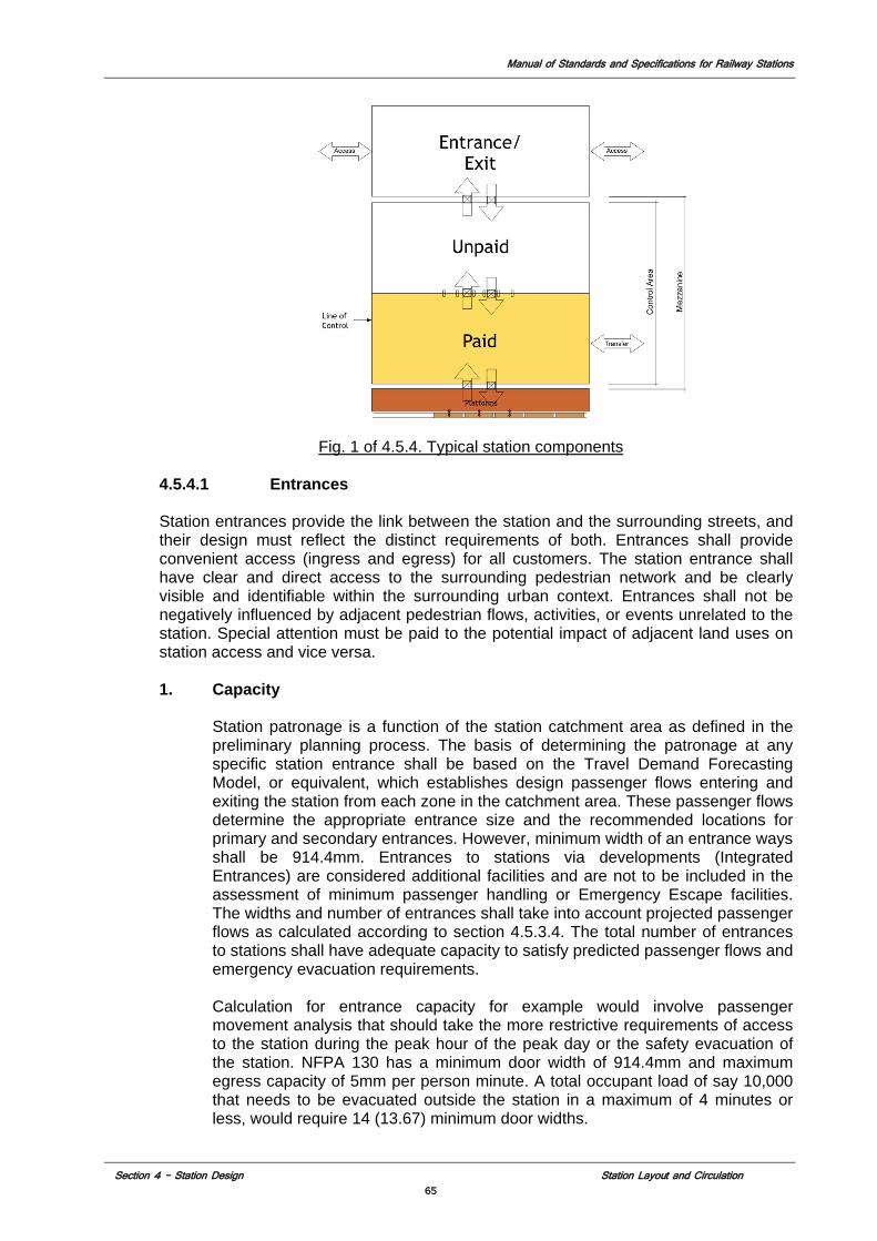
Manual of Standards and Specifications for Railway Stations
Section 4 – Station Design Station Layout and Circulation 65
Fig. 1 of 4.5.4. Typical station components
4.5.4.1 Entrances Station entrances provide the link between the station and the surrounding streets, and their design must reflect the distinct requirements of both. Entrances shall provide convenient access (ingress and egress) for all customers. The station entrance shall have clear and direct access to the surrounding pedestrian network and be clearly visible and identifiable within the surrounding urban context. Entrances shall not be negatively influenced by adjacent pedestrian flows, activities, or events unrelated to the station. Special attention must be paid to the potential impact of adjacent land uses on station access and vice versa.
1. Capacity
Station patronage is a function of the station catchment area as defined in the preliminary planning process. The basis of determining the patronage at any specific station entrance shall be based on the Travel Demand Forecasting Model, or equivalent, which establishes design passenger flows entering and exiting the station from each zone in the catchment area. These passenger flows determine the appropriate entrance size and the recommended locations for primary and secondary entrances. However, minimum width of an entrance ways shall be 914.4mm. Entrances to stations via developments (Integrated Entrances) are considered additional facilities and are not to be included in the assessment of minimum passenger handling or Emergency Escape facilities. The widths and number of entrances shall take into account projected passenger flows as calculated according to section 4.5.3.4. The total number of entrances to stations shall have adequate capacity to satisfy predicted passenger flows and emergency evacuation requirements. Calculation for entrance capacity for example would involve passenger movement analysis that should take the more restrictive requirements of access to the station during the peak hour of the peak day or the safety evacuation of the station. NFPA 130 has a minimum door width of 914.4mm and maximum egress capacity of 5mm per person minute. A total occupant load of say 10,000 that needs to be evacuated outside the station in a maximum of 4 minutes or less, would require 14 (13.67) minimum door widths.
Manual of Standards and Specifications for Railway Stations
Section 4 – Station Design Station Layout and Circulation 66
2. Urban Context
Station entrance shall be sited and designed integrating the local planned development, heritage issues, adaptive reuse, and shall incorporate existing urban resources wherever possible. In historically sensitive areas and in heritage buildings, the entrance and the station building design shall fit seamlessly into the context, adhering to all applicable codes and regulations.
3. Doors
The size of the opening shall be in accordance with passenger/customer movement/volume and capacity. The size, type and direction of swing of the doors at the entrance/exit openings shall be in accordance with building code and NFPA requirements for egress, and safety.
4 Entrance Canopies/Enclosure
Entrances and VCEs shall be protected from the weather. Escalators shall be sheltered as per ASME A17.1/Equivalent Indian Standard. Entrance canopies provide weather protection and are another visual identifying element, providing system recognition. Entrance canopy designs may also incorporate signage and lighting (wherever feasible).
5 General Requirements
a) Accessibility: At least one entrance per station shall be fully handicap accessible as per the Indian Disability Act and ADAAG and shall be integrated with the accessible paths within the local pedestrian network.
b) Efficient path: Access to the VCEs at the entry shall be as direct as possible, and the access path to and from the station interior shall be clearly designated architecturally (e.g., through the use of materials and spatial design and through the use of appropriate signage).
c) Weather protection: All VCEs shall be protected from the weather.
4.5.4.2 Control Area The station control area is the primary decision and activity point in the station’s passenger circulation system. This often leads to a build-up of queue at key entry nodes where passengers pause to orient themselves. The fare array shall be designed to minimize constraints on customer flow. The line of control should be designed to be as visually transparent as possible, to facilitate surveillance and a sense of safety and openness. The station control area is located in the unpaid area contains fare vending, control access to paid areas, and customer information facilities. In addition the unpaid area may contain certain amenities to be provided by the concessionaire and MOR at their discretion. They include: Shops (food and retail) Travel Information Centers Toilets ATM’s Foreign Exchange Centers
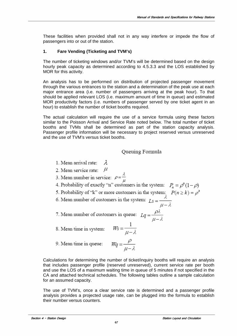
Manual of Standards and Specifications for Railway Stations
Section 4 – Station Design Station Layout and Circulation 67
These facilities when provided shall not in any way interfere or impede the flow of passengers into or out of the station. 1. Fare Vending (Ticketing and TVM’s) The number of ticketing windows and/or TVM’s will be determined based on the design hourly peak capacity as determined according to 4.5.3.3 and the LOS established by MOR for this activity. An analysis has to be performed on distribution of projected passenger movement through the various entrances to the station and a determination of the peak use at each major entrance area (i.e. number of passengers arriving at the peak hour). To that should be applied relevant LOS (i.e. maximum amount of time in queue) and estimated MOR productivity factors (i.e. numbers of passenger served by one ticket agent in an hour) to establish the number of ticket booths required. The actual calculation will require the use of a service formula using these factors similar to the Poisson Arrival and Service Rate noted below. The total number of ticket booths and TVMs shall be determined as part of the station capacity analysis. Passenger profile information will be necessary to project reserved versus unreserved and the use of TVM’s versus ticket booths.
Calculations for determining the number of ticket/inquiry booths will require an analysis that includes passenger profile (reserved unreserved), current service rate per booth and use the LOS of a maximum waiting time in queue of 5 minutes if not specified in the CA and attached technical schedules. The following tables outline a sample calculation for an assumed capacity. The use of TVM’s, once a clear service rate is determined and a passenger profile analysis provides a projected usage rate, can be plugged into the formula to establish their number versus counters.
Manual of Standards and Specifications for Railway Stations
Section 4 – Station Design Station Layout and Circulation 68
2. Ticketing/Information
The ticketing area at the station shall be well defined spatially and conveniently. Located out of the main stream traffic flow, ticket counters shall be easily accessible to passengers purchasing tickets or requiring purchase related information. Booths are to be grouped together in continuous arrays the proximity to the entry gates to the paid area and near the main train information display. Provide a queuing area at least 7.621 m deep with ample space for queuing with luggage, clear to any obstruction, outside the zone of normal passenger circulation and all other queuing areas, unless the need for a lesser queuing area can be verified by passenger modeling. A set of dimensions and specific space requirements for ticket booths is included in the annexures to the manual. It should serve as a general guideline for developing the ticketing arrays. Concessionaire shall obtain through the IE approval from MOR for the actual number and configuration of tickets/Inquiry booths. Features to include:
a) At least one window in each array shall be handicap accessible. b) The windows shall be located centrally for travelers’ convenience and in
accordance with the approved functions flow of the station. c) The windows should be so located that the circulation at the entrance or
exit from the station or the waiting hall is not affected by the queues in front of the Booking Windows. The length of the queue can be estimated at the rate of .5m per person waiting in the queue.
d) A standardized layout for the windows shall be as noted in 4.11 and shall be formulated on the basis of the space requirements provided by MOR for specific stations.
e) Partitions between Passenger-Booking clerks shall be of safety glass with an opening for intercommunication at heights as per the code requirements for both regular and handicap accessible height.
f) The Enquiry and Booking offices shall be lit according to the requirements of the Lighting Section (Section 4.7.4).
g) At least one booth will be equipped with provisions for hearing impaired passengers (see section 4.3.2.9).
h) Booths shall be air conditioned. 3. TVMs (Ticket Vending Machines)
TVM’s will, in addition to dispensing tickets, provide reservation information. All TVM’s will be handicap accessible. Provide a queuing area of at least 3.658 m deep outside the zone of normal passenger circulation in front of all TVMs and Ticket Vending Counters for customer queuing. The information below should serve as a general guideline for location of the TVM’s. Concessionaire shall obtain through the IE approval from MOR for the actual number and configuration of TVM’s. Features will include a) Preferred location against a wall or recessed, allowing easy access
without interrupting the flow of traffic. If they are recessed, flexibility should be provided for future upgrade;
b) have an inclined top surface if they are freestanding to prevent debris build up
c) Located a minimum of .457 m away from a perpendicular wall to allow the front of the machine to swing open for servicing;
d) not be located against control gates or other access areas e) not be located where they obstruct a clear line of view f) Located a minimum of 1.829 m from public telephones (to preserve
privacy when conducting electronic transaction);
Manual of Standards and Specifications for Railway Stations
Section 4 – Station Design Station Layout and Circulation 69
g) have concealed conduit/cabling; h) Provide a maintenance space/chase for conduits. i) Height above finished floor level shall be maintained for ADAAG/IDA
compliance. j) TVMs shall be able to generate unreserved as well as reserved tickets,
accept paper currency and coins give refund of balance of fare amount, and accept credit/debit cards.
k) Concealed power and data infrastructure shall be provided at each TVM location.
l) Connection to central MOR train information and reserved and unreserved ticketing systems.
4. Interactive Inquiry Centers
a) Interactive Inquiry centers (IIC’s) designed like TVM’s except that they will issue only reserved tickets already paid for. They will not accept any form of payment. They shall be provided throughout the station in both the paid and unpaid areas near ticket booths and entry areas and on departure concourse. Concessionaire shall obtain through the IE approval from MOR for the actual number and configuration of IIC’s. Features will include:
b) Train reservation information. c) Status of availability of reserved train seats d) Schedule of trains and train information status e) Station orientation information f) Multimodal connection information g) Any other type of information MOR at its discretion determines should be
included. h) Connection to central MOR train information, and reserved ticketing
systems.
5. SIC (Station Information Centers)
The Station Information Center shall provide rail road network map locating the station, vicinity map locating station in local street area, station plan locating platform, tracks, and ticketing and access areas, and local assistance numbers such as tourist information, police, hospital etc. Provide a reservoir space of at least 2.439 m deep outside the zone of normal passenger circulation in front of the SIC, for customer service queuing. The information below should serve as a general guideline for developing the SIC’s. Concessionaire shall obtain through the IE approval from MOR for the actual number and configuration of SIC’s. The station information centers shall be designed so that in the future the station information system might convert this area into an interactive electronic inquiry center. Design and location of SIC’s shall include the following a) Width of sign shall be a minimum of 3.5 m wide. b) Sign shall start at 0.5 m from the floor and shall be at least 1.5 m high to
the top of the map area. c) The SIC shall have a continuous .25 m high strip providing identification
information. d) It can be wall mounted or free standing in which case both sides will have
the same information. e) Entire sign shall be down lit by a continuous fixture at the top.
Manual of Standards and Specifications for Railway Stations
Section 4 – Station Design Station Layout and Circulation 70
f) Construction shall be of incombustible material with a finished metal frame and map boards shall be of enameled metal or similar type finish on which to mount map information.
g) SIC to have data and power infrastructure built into and concealed into the frame and available to each of the three portions of the sign.
h) SIC’s shall be located within the station building at: • in the unpaid part of the station near every entry area to the paid
part of the station • In the departure and arrival concourses located in the vicinity of
the platform access points no more than 300 m apart. • At each of the main exit points of the station including access to
multimodal connections.
6. Control Gates
Control gates shall be arrayed in groups at the major entrance areas to the paid section with the number based on analysis of capacity and flow requirements. Dimensions and spacing or gates must provide at a minimum for access of one customer with a large piece of luggage. Number of gates shall be as required by capacity projection, gate size and configuration will require specific approval by MOR for each station (see section 4.11.6.12). Barriers shall extend to the height of approximately 2.08 m above floor level that can be closed when not in use. Means should be provided to prevent the visually impaired from walking into the closed gates. A set of dimensions and specific space requirements for control gates is included in the annexures to the manual. It should serve as a general guideline for developing the ticketing arrays. Concessionaire shall obtain through the IE approval from MOR for the actual number and configuration of control gates shall have the following features: a) Number of access and egress gates provided at each control area shall
be adequate for projected ridership and egress and safe evacuation during an emergency. Furthermore, egress capacity in the event of an incident also needs to be considered for NFPA 101 compliance.
b) Width large enough to permit person with luggage or with a trolley to pass through comfortably.
c) At least on gate in each array shall be accessible by wheel chair. d) At least one gate in each array to be designed to accommodate full
security check (luggage scanning, personal scanning and CCTV). See section 4.2.
e) Design should permit transparent view of paid area when gate is closed. f) Each array of control gates providing access to paid area shall have a
number of gates provided with power and data infrastructure as called or in the security schedule to the CA.
7. Tourist Information Booth
a) A tourist information booth shall be provided in the main entry area to the station. It shall be located at a place where it would be easily visible from the main access to the station but out of the direction of main passenger movement. Concessionaire shall obtain through the IE approval from MOR for the actual number and configuration of tourist information booth. Features to include:
b) Booth will be an open configuration free standing pavilion with a covered ceiling.
Manual of Standards and Specifications for Railway Stations
Section 4 – Station Design Station Layout and Circulation 71
c) Booth shall be a minimum of 3 m by 3 m with a .25 m counter going around entire booth.
d) Counter shall be 1 m from the floor. e) Open booth area shall extend 1 m from the counter. f) Booth shall be down lit by a fixture at the top. g) Construction shall be of incombustible material with a finished metal
frame. h) Booth to have data and power infrastructure built into and concealed into
the frame and available to two sides.
8. Foreign Currency Exchange
A foreign currency exchange counter shall be provided in the unpaid part of the station located in proximity to the ticket booths and tourist information booth. Its requirements shall be identical to the ticket booths except that it will be a stand alone both with only one secure entrance that can be locked. Concessionaire shall obtain through the IE approval from MOR for the actual number and configuration of foreign currency exchange booths. It will require one additional feature which is provision for posting an electronic sign that has the currency exchange rates noted and visible on the outside of the booth.
4.5.4.3 Concourses 1. Capacity
Station patronage is a function of the station catchment area as defined in the preliminary planning process. The basis of determining the patronage at any specific station entrance shall be based on the Travel Demand Forecasting Model, or equivalent, which establishes design passenger flows entering and exiting the station from each zone in the catchment area. The concourse area will be determined by this model, the LOS established in section 4.5.3.3 and incorporation of the requirements of the specific type and size of station amenities such as food shops, retail shops etc. that the Concessionaire proposes to include in this space. Calculations for the actual size of a concourse will involve at a minimum the establishment of a peak passenger load for the concourse developed by the model (which may vary from the peak departure load depending on the station operation) times the LOS criteria minus the area to be occupied by amenities and the requisite space factors applied for circulation and access.
2. Design
The design of the concourse and station control areas shall channel and segregate incoming and outgoing passengers to minimize cross-flows and conflicts. Arrival and departure areas should be distinct and separate and where feasible on different levels with no direct passenger connection between them. Arrival areas should be in the direct flow of passenger traffic entering the station and platforms. Departure areas should be remote from arrival areas and facilitate exiting through different station access point from the main arrival areas. Concourse area will be contiguous with all main entry gates and contain the following functions; a) Access to all platforms b) Unreserved waiting areas
Manual of Standards and Specifications for Railway Stations
Section 4 – Station Design Station Layout and Circulation 72
c) Reserved waiting areas d) Lounges e) Toilets f) Cloak room (luggage storage) g) Concessions (food shops, convenience retail shops) h) MOR managed food shops (unreserved waiting areas) i) SIC’s j) TVM’s k) IIC’s l) ATM’s m) Public Security stations Concourse will be the main congregation space for the station. Its design should reflect the highest quality public space aesthetic for public open space. The finishing materials used should be of the highest durability and be of appropriate acoustic qualities. The amenities contained there in should be arranged to facilitate the efficient and comfortable movement of passengers through the space and accommodate the amenities noted above in an orderly and visually pleasing manner. The space should be organized so as the facilitate wayfinding from the entrance to the paid concourse area to the departure platforms requiring a minimal amount of signage. The environmental systems should maintain the main departure Concourse space at a maximum of 29o F and should maximize the amount of natural light and ventilation. All other enclosed passenger spaces on concourse besides toilets shall be air-conditioned according to NBC standards.
4.5.4.4 VCEs (Vertical Circulation Elements)
VCEs are the devices used to transport customers between different levels of the station. VCEs comprise of elevators, escalators, and stairs (including emergency egress stairs). Capacity requirements for VCE’s will be determined on a component by component basis. The most critical will be the platform which is the basic unit of operation in the train station. VCE requirements for a typical platform will be highlighted in a sample calculation in section 4.5.4.5. General planning principles for each type of VCE follow.
• Provide Escalator/Stair Pairs - Wherever feasible, stairs and escalators
shall be provided side-by-side to facilitate a choice in vertical travel. • Provide Elevators in Pairs – Unless infeasible on existing platform areas
elevators shall be installed in pairs side by side wherever they are use for public access.
• Provide Adequate Capacity (Minimum Number of VCEs) -The minimum number of VCEs will be determined by the level of service, given the forecast peak passenger design loads or emergency egress requirements, whichever is most stringent. However, a single upward escalator and stair pair will be considered as the minimum vertical circulation unit at any point of vertical circulation.
Manual of Standards and Specifications for Railway Stations
Section 4 – Station Design Station Layout and Circulation 73
1. Escalators
Where possible, the escalators shall be evenly distributed along the whole length of the station so as to avoid a concentration of passengers at a particular area. An escalator working point shall preferably be not less than 9 m from any obstruction across the direct path of passengers. Where escalators are arranged in banks, the clear distance from the escalator working point shall be increased by at least 1 m for each additional escalator. Traffic flow across the path of passengers is deemed as an obstruction. Where escalator(s) are provided in the lower portion, the landing between the upper and lower portions shall not be less than 5.5 m free length from the escalator working points. If the entrance is angled there shall be not less than 4 m straight from the working point, but if there is a choice of direction not less than 5.5 m. Features shall include: • A smoke containment bulkhead shall be provided at the foot of all stairs
and escalators serving the platform level. It shall extend to the structural soffit from a height of 3 m above the platform finished floor level.
• The minimum distance between working points of escalators working in opposing directions is 17 m.
• Where possible, passengers shall not have to travel from one passenger level to the next by more than one escalator. However all escalators and stair cases provided for interchange passenger flows from a level below ground to a level above ground shall preferably have a break at ground level for emergency evacuation facility.
• All escalators shall be of the heavy-duty reversible type with a design maximum practical capacity of 90 persons per minute based on a service speed of 0.65 m/sec. The following requirements are given for general planning purposes: • Inclination 30 degrees • Step speed 0.65 m/s • Step width (min) 1000 mm • Number of flat steps at upper landing 4 (min) • Number of flat steps at lower landing 4 (min)
a) Application i) Provide an escalator where the vertical path of travel exceeds
3.658 m. ii) At least one path of vertical egress assisted by an escalator shall
be available from any point in the station in both directions. b) Level of Service -The following performance standards will be used for
station planning. i) 1219 mm nominal (two-lane) escalator. ii) Capacity: Approximately 90 persons per minute. (see 4.5.4.5 for
capacity for calculation emergency egress) iii) Queuing areas: LOS C.
c) Location i) Escalators shall be located along the normal and direct path of
passenger circulation and be visible and easily identifiable as a means of access to the levels they connect.
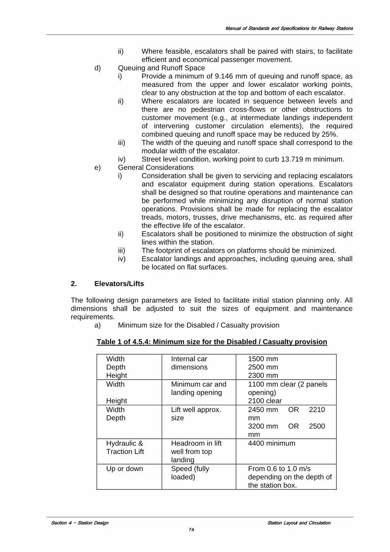
Manual of Standards and Specifications for Railway Stations
Section 4 – Station Design Station Layout and Circulation 74
ii) Where feasible, escalators shall be paired with stairs, to facilitate efficient and economical passenger movement.
d) Queuing and Runoff Space i) Provide a minimum of 9.146 mm of queuing and runoff space, as
measured from the upper and lower escalator working points, clear to any obstruction at the top and bottom of each escalator.
ii) Where escalators are located in sequence between levels and there are no pedestrian cross-flows or other obstructions to customer movement (e.g., at intermediate landings independent of intervening customer circulation elements), the required combined queuing and runoff space may be reduced by 25%.
iii) The width of the queuing and runoff space shall correspond to the modular width of the escalator.
iv) Street level condition, working point to curb 13.719 m minimum. e) General Considerations
i) Consideration shall be given to servicing and replacing escalators and escalator equipment during station operations. Escalators shall be designed so that routine operations and maintenance can be performed while minimizing any disruption of normal station operations. Provisions shall be made for replacing the escalator treads, motors, trusses, drive mechanisms, etc. as required after the effective life of the escalator.
ii) Escalators shall be positioned to minimize the obstruction of sight lines within the station.
iii) The footprint of escalators on platforms should be minimized. iv) Escalator landings and approaches, including queuing area, shall
be located on flat surfaces.
2. Elevators/Lifts The following design parameters are listed to facilitate initial station planning only. All dimensions shall be adjusted to suit the sizes of equipment and maintenance requirements.
a) Minimum size for the Disabled / Casualty provision
Table 1 of 4.5.4: Minimum size for the Disabled / Casualty provision
Width Depth Height
Internal car dimensions
1500 mm 2500 mm 2300 mm
Width Height
Minimum car and landing opening
1100 mm clear (2 panels opening) 2100 clear
Width Depth
Lift well approx. size
2450 mm OR 2210 mm 3200 mm OR 2500 mm
Hydraulic & Traction Lift
Headroom in lift well from top landing
4400 minimum
Up or down Speed (fully loaded)
From 0.6 to 1.0 m/s depending on the depth of the station box.
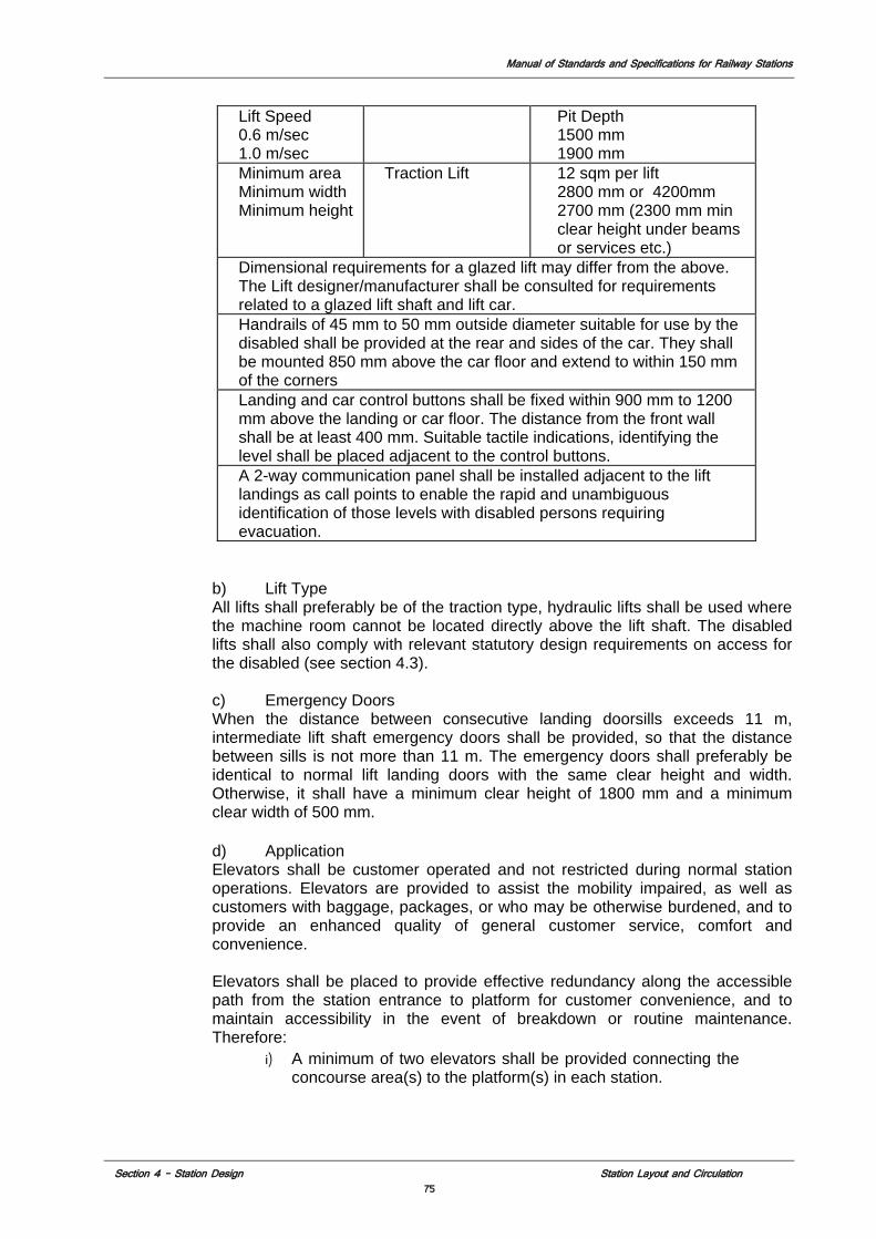
Manual of Standards and Specifications for Railway Stations
Section 4 – Station Design Station Layout and Circulation 75
Lift Speed 0.6 m/sec 1.0 m/sec
Pit Depth 1500 mm 1900 mm
Minimum area Minimum width Minimum height
Traction Lift 12 sqm per lift 2800 mm or 4200mm 2700 mm (2300 mm min clear height under beams or services etc.)
Dimensional requirements for a glazed lift may differ from the above. The Lift designer/manufacturer shall be consulted for requirements related to a glazed lift shaft and lift car. Handrails of 45 mm to 50 mm outside diameter suitable for use by the disabled shall be provided at the rear and sides of the car. They shall be mounted 850 mm above the car floor and extend to within 150 mm of the corners Landing and car control buttons shall be fixed within 900 mm to 1200 mm above the landing or car floor. The distance from the front wall shall be at least 400 mm. Suitable tactile indications, identifying the level shall be placed adjacent to the control buttons. A 2-way communication panel shall be installed adjacent to the lift landings as call points to enable the rapid and unambiguous identification of those levels with disabled persons requiring evacuation.
b) Lift Type All lifts shall preferably be of the traction type, hydraulic lifts shall be used where the machine room cannot be located directly above the lift shaft. The disabled lifts shall also comply with relevant statutory design requirements on access for the disabled (see section 4.3).
c) Emergency Doors When the distance between consecutive landing doorsills exceeds 11 m, intermediate lift shaft emergency doors shall be provided, so that the distance between sills is not more than 11 m. The emergency doors shall preferably be identical to normal lift landing doors with the same clear height and width. Otherwise, it shall have a minimum clear height of 1800 mm and a minimum clear width of 500 mm.
d) Application Elevators shall be customer operated and not restricted during normal station operations. Elevators are provided to assist the mobility impaired, as well as customers with baggage, packages, or who may be otherwise burdened, and to provide an enhanced quality of general customer service, comfort and convenience. Elevators shall be placed to provide effective redundancy along the accessible path from the station entrance to platform for customer convenience, and to maintain accessibility in the event of breakdown or routine maintenance. Therefore:
i) A minimum of two elevators shall be provided connecting the concourse area(s) to the platform(s) in each station.
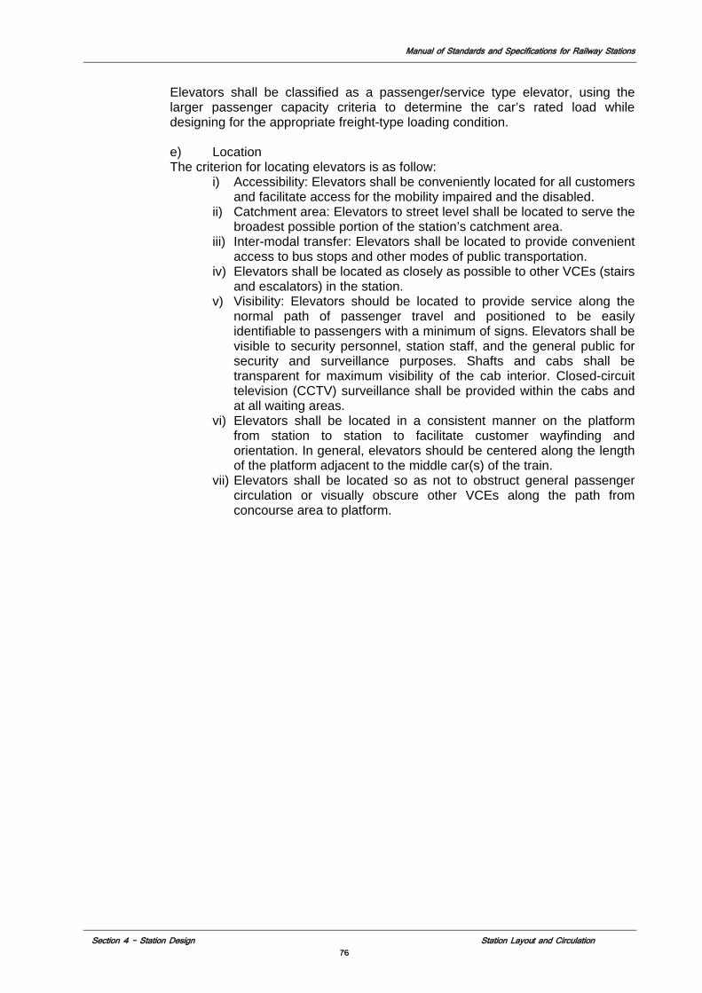
Manual of Standards and Specifications for Railway Stations
Section 4 – Station Design Station Layout and Circulation 76
Elevators shall be classified as a passenger/service type elevator, using the larger passenger capacity criteria to determine the car’s rated load while designing for the appropriate freight-type loading condition. e) Location The criterion for locating elevators is as follow:
i) Accessibility: Elevators shall be conveniently located for all customers and facilitate access for the mobility impaired and the disabled.
ii) Catchment area: Elevators to street level shall be located to serve the broadest possible portion of the station’s catchment area.
iii) Inter-modal transfer: Elevators shall be located to provide convenient access to bus stops and other modes of public transportation.
iv) Elevators shall be located as closely as possible to other VCEs (stairs and escalators) in the station.
v) Visibility: Elevators should be located to provide service along the normal path of passenger travel and positioned to be easily identifiable to passengers with a minimum of signs. Elevators shall be visible to security personnel, station staff, and the general public for security and surveillance purposes. Shafts and cabs shall be transparent for maximum visibility of the cab interior. Closed-circuit television (CCTV) surveillance shall be provided within the cabs and at all waiting areas.
vi) Elevators shall be located in a consistent manner on the platform from station to station to facilitate customer wayfinding and orientation. In general, elevators should be centered along the length of the platform adjacent to the middle car(s) of the train.
vii) Elevators shall be located so as not to obstruct general passenger circulation or visually obscure other VCEs along the path from concourse area to platform.
Manual of Standards and Specifications for Railway Stations
Section 4 – Station Design Station Layout and Circulation 77
Fig. 2 of 4.5.4.: A cross section of the Elevator and the Landing Area
f) Size i) Elevators shall be of a minimum size for emergency medical service,
in order to accommodate a gurney and to comply with all other Accessibility requirements. Consideration should also be given to local rider-ship characteristics in selecting elevator sizes (e.g., passengers with baggage).
g) Queuing Space i) The elevator landing depth (the queuing and discharge space at
the elevator door) shall be a minimum clear distance to any obstruction equal to one and a half times the depth of the car or 3.048 m, whichever is greater, by the width of the elevator.
ii) Elevator landings shall be positioned so that the elevator queuing area does not impede general circulation, is clearly visible and has adequate queuing space.
iii) Queuing space shall not overlap with other queuing areas from other VCEs, fare gates, stairs, equipment, etc.
h) Level of Service - Elevator queuing LOS C i) Capacity – Based on NFPA 101 elevator capacity should be at least 8
with a minimum of .28m per person per cab for establishing elevator capacity for evacuation of permitted spaces. Using these standards a minimum size elevator (1.5 by 2.5) will carry 13 passengers and move fully loaded at approximately 1 m per second.
j) General Considerations
Manual of Standards and Specifications for Railway Stations
Section 4 – Station Design Station Layout and Circulation 78
i) Platform level elevators shall not open in the direction of the platform edge.
ii) Consideration shall be given to servicing and replacing elevators and elevator equipment during station operations. Elevators shall be designed so that routine operations and maintenance can be easily performed without disrupting normal station operations. Provisions shall be made for replacing the elevator cab, motors, hydraulics, drive mechanisms, etc., as required after their effective life.
iii) Elevators shall comply with Indian Disability Act and ADAAG for all regulations on operation, controlling heights, and identification and emergency communication while using a larger car as described.
iv) Escalator landings and approaches, including queuing areas, shall be located flat surfaces.
3. Ramps
Ramps shall only be used for small changes in level or for use by wheelchairs and the following gradients shall apply: a) preferred gradient 1:20 b) maximum gradient 1:12 Ramps shall be a minimum width of 1200mm for unidirectional movement and 1500mm for bi-directional movement. Rest platforms should be considered for long ramps (exceeding 10m) provided for wheelchair users. Rest platforms should provide a level area 1800mm long at intervals of approximately10m. Capacity of ramp as defined in NFPA 130 as .0819 per millimeter per person per minute. Minimum size of ramp is .914m.
4. Stairs
Public stairs are intended for normal passenger circulation. Because of the safety hazards and energy expenditure associated with human locomotion on a stairway, designers must be particularly cognizant of the passenger behavior and traffic patterns of railway stations. a) Level of Service The following LOS performance standards shall be used for station planning:
i) Stairs: LOS C ii) Queuing areas: LOS C iii) Capacity (see 4.5.4.5 for capacity calculation for emergency
egress). b) Application
i) Stairs are the primary mode of vertical circulation for meeting emergency egress requirements (e.g., NFPA 130).
ii) Stairs shall be used as the primary mode of vertical circulation where the vertical rise between levels is less than 2.439 m
iii) Stairs are recommended as the primary mode of vertical circulation for the downward movement of customers where the vertical rise between levels is less than 6.097 m
Manual of Standards and Specifications for Railway Stations
Section 4 – Station Design Station Layout and Circulation 79
iv) Stairs should not be provided as a means of normal public access (as distinguished from emergency egress) where the vertical rise between levels exceeds 10.975 m.
c) Location i) Stairs shall be located along the normal and direct path of
passenger circulation and be visible and easily identifiable as means of access to the levels they connect.
ii) Wherever feasible, stairs shall be paired with escalators to facilitate efficient and economical passenger movement.
d) Width i) Wherever practicable, all stairs shall be planned using modular
width corresponding to the applicable escalator module used in the station design (including installation and construction tolerances), and designed to facilitate replacement by an escalator in the future.
ii) Where use of an escalator width as a modular dimension is not possible or appropriate, the minimum width of a stair shall be 1.524 m or as determined by passenger demand based on LOS, service standard, or emergency egress requirements.
e) Queuing and Runoff Space Adequate queuing and runoff space must be provided at the top and bottom of all stairs. Where a stair is paired with an escalator, the queuing and runoff areas shall coincide with that of the adjacent escalator. Where a stair is not adjacent to or does not align with an escalator, provide a minimum of queuing and runoff area equal to the width of the stair or 3.048 m, whichever is greater.
Space shall be provided for queuing at all circulation and passenger service elements. The queuing area provides space for passengers to queue at various circulation elements, service areas and decision points without disrupting the movement of other passenger flow routes. Queuing spaces shall be placed end to end; and shall not overlap. They shall be considered as part of the general space requirements for any given area, as indicated below: f) Height and Run The rise of the stairs shall preferably be limited to 3500 mm. However, specific site conditions may cause an increase in this dimension. For greater rise heights, the entrances shall be divided into two portions, the upper portion consisting of stairs for both up and down movement and the lower portion consisting of an escalator for upward movement and a staircase for downward movement. A staircase taking traffic from an escalator shall be of sufficient width to provide capacity at least equal to the escalator.
. g) Design Parameters Continuous flights of stairs for use by the public shall have the following design parameters:
Manual of Standards and Specifications for Railway Stations
Section 4 – Station Design Station Layout and Circulation 80
Risers per flight 3 No (minimum) 12 No
Height of riser (subject to pitch)
150 mm (maximum)
Length of tread (subject to pitch)
300 mm (minimum)
Stair width 1800mm or 3 lanes (minimum) for normal movement of passengers. 1200mm or 2 lanes (minimum) for emergency use of passengers.
Length of intermediate landings
Lesser of 2000 mm or width of stairs.
Length of Flood Landing (entrances with stairs only)
2500 mm (minimum)
Vertical Clearance 2700 mm (min.) measured from the finished step level (on line of nosings) to underside of suspended ceiling 2350 mm (min.) measured from finished step level to underside of signs.
Handrail 850 mm high, 50 mm diameter 45 mm clearance between handrail and inside balustrade or wall finish.
Falls at entrance stairs Flood landings are to fall 1:100 towards the street with side channels. Intermediate landings are to fall towards the concourse.
i) The width of a staircase shall be measured from the finished
surfaces of the inside faces of the balustrades or staircase walls. The only permitted projection into this width shall be the handrail. No open risers shall be allowed.
ii) These standards refer to all stairways used by the public including auxiliary staircases. All staircases shall comply with local regulations.
h) General Considerations
i) The stairway must be well lit. ii) Provisions shall be made to facilitate the maintenance and
cleaning of the stair (e.g., the provision of runnels on either side of the stair tread to facilitate channeling water and debris down the stairs for cleaning).
iii) Stair design (riser, tread, and railing configurations) should be designed to promote comfort and ease of use, and meet all applicable code requirements.
iv) When a stair runs along side of an escalator, the angle of the stair nosings shall be aligned with those of the escalator (at 30 degrees) and shall be at or below the line of the escalator treads,
Manual of Standards and Specifications for Railway Stations
Section 4 – Station Design Station Layout and Circulation 81
such that the top of the stair handrail will be at or below the height of the escalator balustrade.
v) Stair landings and approaches, including queuing areas, shall be located on flat surfaces.
5. Travelators
Where there are substantial distances to be traversed within stations and /or between stations and intermodal connections the use of a travelators (people mover) may be considered. Design considerations when their use is proposed include: a) parallel walkways to travelator b) direction of travel should be shown clearly and the footway at both ends
should be marked by colour contrast and a change in floor finish c) The travelator must be well lit, particularly at its entrance and exit. d) Moving handrails should be rounded in section, in a colour which
contrasts with the background and should extend approximately 700mm beyond the beginning of the walkway
e) The recommended width is 1500mm f) Side panels should be finished in a non-reflective surface g) The recommended speed of movement of the 0.5m/second
(0.75m/second maximum). h) The surface should be non-slip and there should be clearly visible
emergency stop switches that can be reached and operated by disabled people.
i) An audible warning at the beginning and prior to the end of the travelator j) Should have a minimum unobstructed level run-off at each end of 6 m. k) The maximum gradient should be 5 per cent (1 in 20) Reference Department of Transport –Inclusive Mobility (UK)
6. Left-Hand Circulation (The “Left-Hand Rule”)
VCEs shall be positioned to encourage left-hand circulation and minimize conflicting passenger movement and cross-flows. When a stair and escalator are planned for side-by-side installation, the stair shall be placed to the left-hand side of the escalator when looking down. Similarly, down escalators shall be positioned to the left of up escalators when looking down. This strategy will encourage the use of stairs for descending movements and minimize crossing movements at landings. Station equipment (e.g., TVMs and fare gates) and amenities shall also be positioned to avoid having passengers cross the left-hand circulation pattern. Station design and directional signage shall be developed to encourage and support left-hand passenger circulation. Refer to Signage and Graphics section (4.11).
7. Modular Planning and Interchangeability
Escalators and stairs shall be sized in modular units of width, based on the width of the escalator planned for use in the station in order to permit the future replacement of stairs with escalators (or escalators with stairs) as dictated by passenger demand. The planning module shall include provisions for external escalator drives if applicable. Structural, mechanical, and spatial provisions shall be made during design to accommodate the future interchangeability of stairs and escalators in the original construction (see section 4.4).
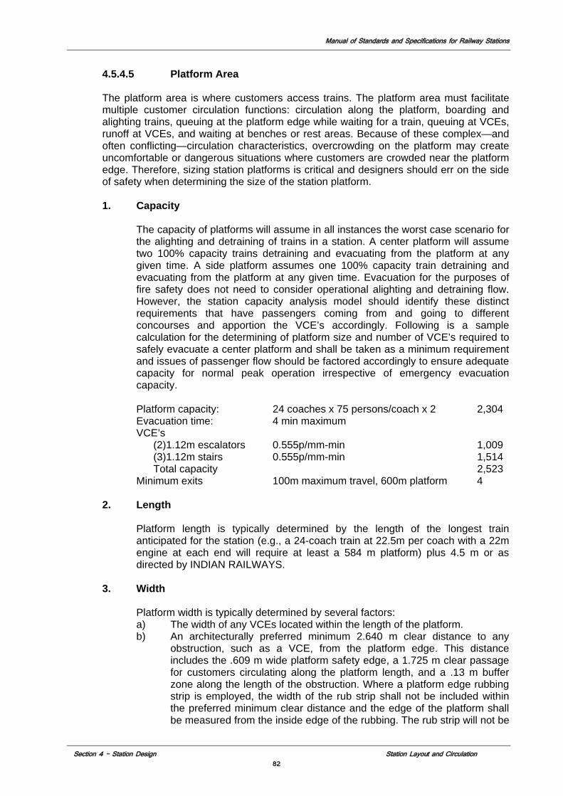
Manual of Standards and Specifications for Railway Stations
Section 4 – Station Design Station Layout and Circulation 82
4.5.4.5 Platform Area The platform area is where customers access trains. The platform area must facilitate multiple customer circulation functions: circulation along the platform, boarding and alighting trains, queuing at the platform edge while waiting for a train, queuing at VCEs, runoff at VCEs, and waiting at benches or rest areas. Because of these complex—and often conflicting—circulation characteristics, overcrowding on the platform may create uncomfortable or dangerous situations where customers are crowded near the platform edge. Therefore, sizing station platforms is critical and designers should err on the side of safety when determining the size of the station platform. 1. Capacity
The capacity of platforms will assume in all instances the worst case scenario for the alighting and detraining of trains in a station. A center platform will assume two 100% capacity trains detraining and evacuating from the platform at any given time. A side platform assumes one 100% capacity train detraining and evacuating from the platform at any given time. Evacuation for the purposes of fire safety does not need to consider operational alighting and detraining flow. However, the station capacity analysis model should identify these distinct requirements that have passengers coming from and going to different concourses and apportion the VCE’s accordingly. Following is a sample calculation for the determining of platform size and number of VCE’s required to safely evacuate a center platform and shall be taken as a minimum requirement and issues of passenger flow should be factored accordingly to ensure adequate capacity for normal peak operation irrespective of emergency evacuation capacity. Platform capacity: 24 coaches x 75 persons/coach x 2 2,304 Evacuation time: 4 min maximum VCE’s (2)1.12m escalators 0.555p/mm-min 1,009 (3)1.12m stairs 0.555p/mm-min 1,514 Total capacity 2,523 Minimum exits 100m maximum travel, 600m platform 4
2. Length Platform length is typically determined by the length of the longest train anticipated for the station (e.g., a 24-coach train at 22.5m per coach with a 22m engine at each end will require at least a 584 m platform) plus 4.5 m or as directed by INDIAN RAILWAYS.
3. Width
Platform width is typically determined by several factors: a) The width of any VCEs located within the length of the platform. b) An architecturally preferred minimum 2.640 m clear distance to any
obstruction, such as a VCE, from the platform edge. This distance includes the .609 m wide platform safety edge, a 1.725 m clear passage for customers circulating along the platform length, and a .13 m buffer zone along the length of the obstruction. Where a platform edge rubbing strip is employed, the width of the rub strip shall not be included within the preferred minimum clear distance and the edge of the platform shall be measured from the inside edge of the rubbing. The rub strip will not be
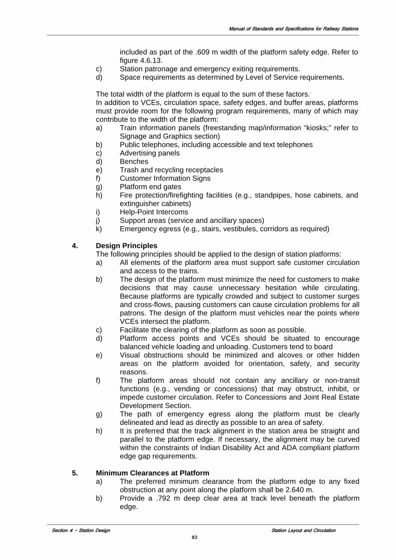
Manual of Standards and Specifications for Railway Stations
Section 4 – Station Design Station Layout and Circulation 83
included as part of the .609 m width of the platform safety edge. Refer to figure 4.6.13.
c) Station patronage and emergency exiting requirements. d) Space requirements as determined by Level of Service requirements. The total width of the platform is equal to the sum of these factors. In addition to VCEs, circulation space, safety edges, and buffer areas, platforms must provide room for the following program requirements, many of which may contribute to the width of the platform: a) Train information panels (freestanding map/information “kiosks;” refer to
Signage and Graphics section) b) Public telephones, including accessible and text telephones c) Advertising panels d) Benches e) Trash and recycling receptacles f) Customer Information Signs g) Platform end gates h) Fire protection/firefighting facilities (e.g., standpipes, hose cabinets, and
extinguisher cabinets) i) Help-Point Intercoms j) Support areas (service and ancillary spaces) k) Emergency egress (e.g., stairs, vestibules, corridors as required)
4. Design Principles
The following principles should be applied to the design of station platforms: a) All elements of the platform area must support safe customer circulation
and access to the trains. b) The design of the platform must minimize the need for customers to make
decisions that may cause unnecessary hesitation while circulating. Because platforms are typically crowded and subject to customer surges and cross-flows, pausing customers can cause circulation problems for all patrons. The design of the platform must vehicles near the points where VCEs intersect the platform.
c) Facilitate the clearing of the platform as soon as possible. d) Platform access points and VCEs should be situated to encourage
balanced vehicle loading and unloading. Customers tend to board e) Visual obstructions should be minimized and alcoves or other hidden
areas on the platform avoided for orientation, safety, and security reasons.
f) The platform areas should not contain any ancillary or non-transit functions (e.g., vending or concessions) that may obstruct, inhibit, or impede customer circulation. Refer to Concessions and Joint Real Estate Development Section.
g) The path of emergency egress along the platform must be clearly delineated and lead as directly as possible to an area of safety.
h) It is preferred that the track alignment in the station area be straight and parallel to the platform edge. If necessary, the alignment may be curved within the constraints of Indian Disability Act and ADA compliant platform edge gap requirements.
5. Minimum Clearances at Platform
a) The preferred minimum clearance from the platform edge to any fixed obstruction at any point along the platform shall be 2.640 m.
b) Provide a .792 m deep clear area at track level beneath the platform edge.
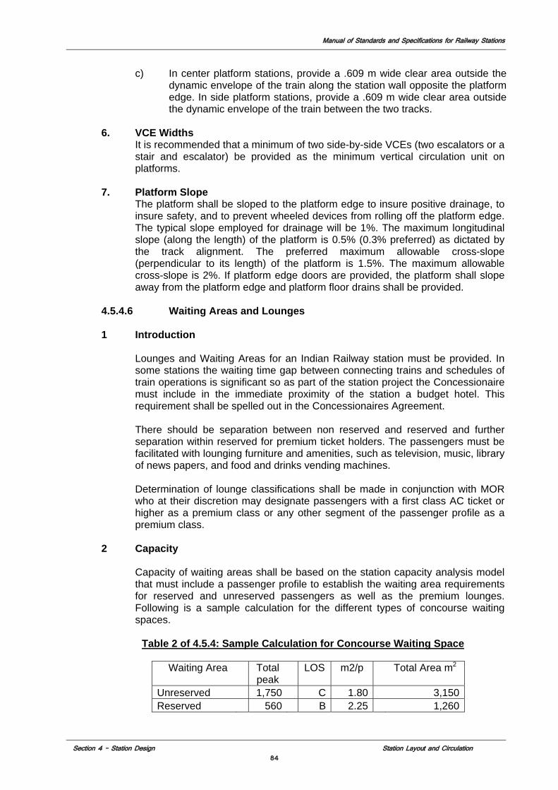
Manual of Standards and Specifications for Railway Stations
Section 4 – Station Design Station Layout and Circulation 84
c) In center platform stations, provide a .609 m wide clear area outside the dynamic envelope of the train along the station wall opposite the platform edge. In side platform stations, provide a .609 m wide clear area outside the dynamic envelope of the train between the two tracks.
6. VCE Widths It is recommended that a minimum of two side-by-side VCEs (two escalators or a stair and escalator) be provided as the minimum vertical circulation unit on platforms.
7. Platform Slope The platform shall be sloped to the platform edge to insure positive drainage, to insure safety, and to prevent wheeled devices from rolling off the platform edge. The typical slope employed for drainage will be 1%. The maximum longitudinal slope (along the length) of the platform is 0.5% (0.3% preferred) as dictated by the track alignment. The preferred maximum allowable cross-slope (perpendicular to its length) of the platform is 1.5%. The maximum allowable cross-slope is 2%. If platform edge doors are provided, the platform shall slope away from the platform edge and platform floor drains shall be provided.
4.5.4.6 Waiting Areas and Lounges 1 Introduction
Lounges and Waiting Areas for an Indian Railway station must be provided. In some stations the waiting time gap between connecting trains and schedules of train operations is significant so as part of the station project the Concessionaire must include in the immediate proximity of the station a budget hotel. This requirement shall be spelled out in the Concessionaires Agreement. There should be separation between non reserved and reserved and further separation within reserved for premium ticket holders. The passengers must be facilitated with lounging furniture and amenities, such as television, music, library of news papers, and food and drinks vending machines. Determination of lounge classifications shall be made in conjunction with MOR who at their discretion may designate passengers with a first class AC ticket or higher as a premium class or any other segment of the passenger profile as a premium class.
2 Capacity
Capacity of waiting areas shall be based on the station capacity analysis model that must include a passenger profile to establish the waiting area requirements for reserved and unreserved passengers as well as the premium lounges. Following is a sample calculation for the different types of concourse waiting spaces.
Table 2 of 4.5.4: Sample Calculation for Concourse Waiting Space
Waiting Area Total peak
LOS m2/p Total Area m2
Unreserved 1,750 C 1.80 3,150 Reserved 560 B 2.25 1,260
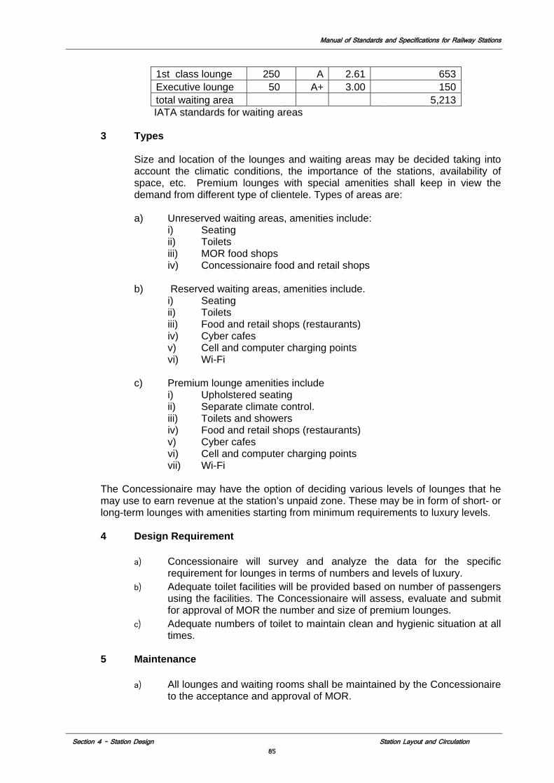
Manual of Standards and Specifications for Railway Stations
Section 4 – Station Design Station Layout and Circulation 85
1st class lounge 250 A 2.61 653 Executive lounge 50 A+ 3.00 150 total waiting area 5,213
IATA standards for waiting areas 3 Types
Size and location of the lounges and waiting areas may be decided taking into account the climatic conditions, the importance of the stations, availability of space, etc. Premium lounges with special amenities shall keep in view the demand from different type of clientele. Types of areas are:
a) Unreserved waiting areas, amenities include:
i) Seating ii) Toilets iii) MOR food shops iv) Concessionaire food and retail shops
b) Reserved waiting areas, amenities include.
i) Seating ii) Toilets iii) Food and retail shops (restaurants) iv) Cyber cafes v) Cell and computer charging points vi) Wi-Fi
c) Premium lounge amenities include
i) Upholstered seating ii) Separate climate control. iii) Toilets and showers iv) Food and retail shops (restaurants) v) Cyber cafes vi) Cell and computer charging points vii) Wi-Fi
The Concessionaire may have the option of deciding various levels of lounges that he may use to earn revenue at the station’s unpaid zone. These may be in form of short- or long-term lounges with amenities starting from minimum requirements to luxury levels.
4 Design Requirement
a) Concessionaire will survey and analyze the data for the specific requirement for lounges in terms of numbers and levels of luxury.
b) Adequate toilet facilities will be provided based on number of passengers using the facilities. The Concessionaire will assess, evaluate and submit for approval of MOR the number and size of premium lounges.
c) Adequate numbers of toilet to maintain clean and hygienic situation at all times.
5 Maintenance
a) All lounges and waiting rooms shall be maintained by the Concessionaire to the acceptance and approval of MOR.
Manual of Standards and Specifications for Railway Stations
Section 4 – Station Design Station Layout and Circulation 86
b) All rest rooms and other amenities including any food service areas connected to lounges must be maintained in accordance with national health and safety requirements and local municipal corporations’ regulations, whichever is more stringent.
4.5.4.7 Public Support Areas The main public areas of the station include the station entrance, the control area, mezzanines, transfer concourses and the station platform (or platforms) as described previously in this Section. The programmatic requirements for these public areas are determined by the capacity and planning and design standards of their respective passenger circulation functions. The following data is provided as an example of the typical requirements for stations and is intended only as an aide in preliminary station planning. Actual programmatic requirements must be developed during the course of preliminary engineering and will vary according to the specific requirements of each station.
1 Public Restrooms
Each station shall have male and female public restrooms located in the paid and unpaid area. Minimum fixture and facility requirements for these restrooms are as follows: a. Men’s Restroom
i) One accessible toilet ii) One urinal iii) Two lavatories with mirror(s) iv) One infant changing table
b) Woman’s Restroom i) One accessible toilet ii) One standard toilet iii) Two lavatories with mirror(s) iv) One infant changing table
Public restrooms shall be fully accessible. Toilet fixtures and urinals will be provided with partial-height partitions for privacy. Toilets will be provided with doors and privacy latches. Doors will not be used at restroom entrances. The entrance to each restroom shall be provided with a vestibule or other means to block direct views into the restroom
4.5.5 Parking and Vehicular Circulation
4.5.5.1 Capacity Considerations Traffic circulation and parking service applies to all areas of the site and should ensure a free flow of traffic at all times of the day and throughout the year. Design year and design passenger load shall be established by MOR for each station. Other station area capacities shall be designed based on the development codes of the local jurisdiction. The capacities shall be designed for the peak hours of the day of the maximum seasonal peak of the design year. A baseline traffic assessment study shall be done to assess the needs and project requirements for the horizon design year. The provision of parking bays shall depend on average parking demand and turnover time and Level of Service C shall be considered for future requirements. Parking accumulation survey, parking duration survey and classified traffic volume surveys at entry / exits shall be done on peak days of the week for duration of 24 hours to determine parking demand in the present condition, modal
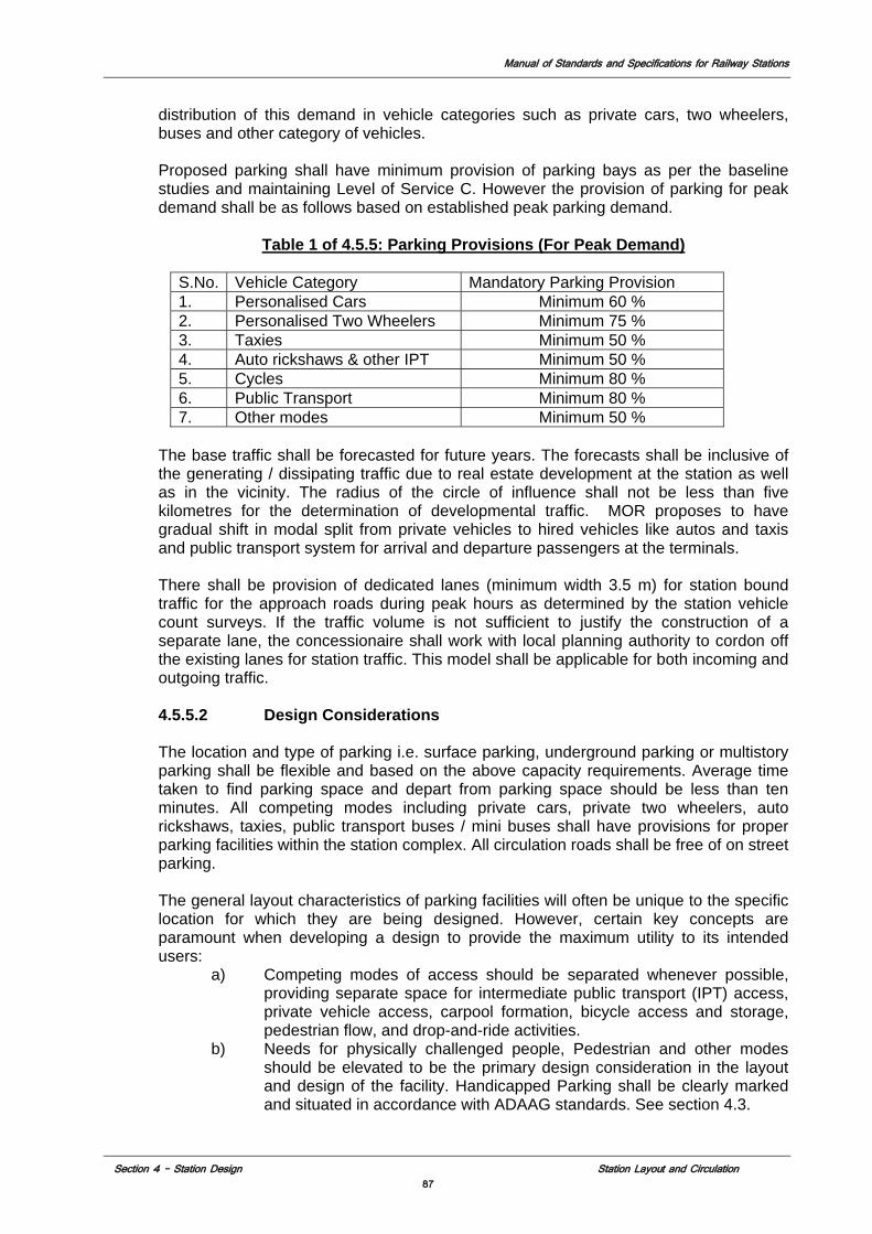
Manual of Standards and Specifications for Railway Stations
Section 4 – Station Design Station Layout and Circulation 87
distribution of this demand in vehicle categories such as private cars, two wheelers, buses and other category of vehicles. Proposed parking shall have minimum provision of parking bays as per the baseline studies and maintaining Level of Service C. However the provision of parking for peak demand shall be as follows based on established peak parking demand.
Table 1 of 4.5.5: Parking Provisions (For Peak Demand)
S.No. Vehicle Category Mandatory Parking Provision 1. Personalised Cars Minimum 60 % 2. Personalised Two Wheelers Minimum 75 % 3. Taxies Minimum 50 % 4. Auto rickshaws & other IPT Minimum 50 % 5. Cycles Minimum 80 % 6. Public Transport Minimum 80 % 7. Other modes Minimum 50 %
The base traffic shall be forecasted for future years. The forecasts shall be inclusive of the generating / dissipating traffic due to real estate development at the station as well as in the vicinity. The radius of the circle of influence shall not be less than five kilometres for the determination of developmental traffic. MOR proposes to have gradual shift in modal split from private vehicles to hired vehicles like autos and taxis and public transport system for arrival and departure passengers at the terminals. There shall be provision of dedicated lanes (minimum width 3.5 m) for station bound traffic for the approach roads during peak hours as determined by the station vehicle count surveys. If the traffic volume is not sufficient to justify the construction of a separate lane, the concessionaire shall work with local planning authority to cordon off the existing lanes for station traffic. This model shall be applicable for both incoming and outgoing traffic. 4.5.5.2 Design Considerations The location and type of parking i.e. surface parking, underground parking or multistory parking shall be flexible and based on the above capacity requirements. Average time taken to find parking space and depart from parking space should be less than ten minutes. All competing modes including private cars, private two wheelers, auto rickshaws, taxies, public transport buses / mini buses shall have provisions for proper parking facilities within the station complex. All circulation roads shall be free of on street parking. The general layout characteristics of parking facilities will often be unique to the specific location for which they are being designed. However, certain key concepts are paramount when developing a design to provide the maximum utility to its intended users:
a) Competing modes of access should be separated whenever possible, providing separate space for intermediate public transport (IPT) access, private vehicle access, carpool formation, bicycle access and storage, pedestrian flow, and drop-and-ride activities.
b) Needs for physically challenged people, Pedestrian and other modes should be elevated to be the primary design consideration in the layout and design of the facility. Handicapped Parking shall be clearly marked and situated in accordance with ADAAG standards. See section 4.3.
Manual of Standards and Specifications for Railway Stations
Section 4 – Station Design Station Layout and Circulation 88
c) Individual access and service modes should be organized within the parking facility to minimize conflicts and maximize the efficiency of the various operations.
d) Provide separate access driveways for various modes and by providing separate access for short term drop-and-ride activities which includes taxis, autos and tourist buses.
e) Clear visibility from the major access points so that drivers can quickly identify if the parking bay is full or if space is available.
f) Messaging system should be considered as an aid to the driver. g) Provide a single continuous path for the commuter from the road to a
parking space and to the railway platform with a minimum of conflicting barriers. Maintaining this goal throughout the design process will provide a convenient and efficient parking facility.
h) Pedestrian access between the parking lot and the primary service mode should provide for convenient access with minimal walking distances (less than 200 meters is preferred).
i) Parking meters and Intelligent Parking Assist System (IPAS ) shall be developed and deployed in the parking lots.
4.5.5.3 Pedestrian Requirements
Pedestrian paths within the parking lot should have the following features a) Clearly distinguishable throughout the facility. b) Minimization of Conflicts between pedestrians and vehicles. c) Raised pedestrian paths and sidewalks are preferable to parking aisles d) Curb spaces immediately adjacent to the loading areas should be free of
all barriers. e) Signage and street furniture, as well as other passenger amenities,
should not interfere with loading, patron queuing, or pedestrian access. f) Spaces should be provided with wheelchair ramps and curb cuts,
textured pavement surfaces, and a barrier-free path between handicap parking spaces and the railway terminal.
g) Adequate space for full deployment and loading of vehicle lifts should be provided adjacent to each parking bay
h) Additional amenities such as Braille signage and audible signals should be considered as aids to visually impaired patrons.
4.5.5.4. Vehicular Circulation
Vehicle circulation strategy within the parking facility shall be based on following features a) Internal Circulation with the parking facility to be based on clockwise
movement. b) Encourage inbound access movement, bringing inbound vehicles on-site
quickly and conveniently to prevent on-street backups at key entrances. c) Facilitate easier access in the peak periods and reduce on-street
congestion. Entrances should allow the accessing driver to drive past as much of the lot as possible before entering, thus allowing visual inspection of the facility for available spaces.
d) Access / Egress and circulation routes shall be free from vehicular and other obstructions maintaining free flow of traffic at all times.
e) All competing modes including private cars, private two wheelers, auto rickshaws, taxies, public transport buses / mini buses shall have provisions for proper circulation, drop off / pick up facilities and parking facilities within the station complex.
Manual of Standards and Specifications for Railway Stations
Section 4 – Station Design Station Layout and Circulation 89
f) All circulations in station area shall be unidirectional and preferably in clockwise direction. Arrivals and departures shall be planned such that there is no conflict of traffic.
g) Drop off and pick up bays shall be provided at most convenient locations. All circulation roads shall be free of On-street parking.
4.5.6 Concession and Commercial Areas
4.5.6.1 Introduction
The major railway stations in metropolitan cities in India are generally centrally located. Therefore, the integration of joint commercial development into railway stations can enrich the station environment, providing convenience as well as substantial revenue generation. Incorporation of concessions into the overall station design involves the seamlessly coordinated efforts between the Indian Railways and the Concessionaire, and must be well integrated into the surrounding community. Concessions are a vital element in the activity of stations, and include retail at station and mezzanine levels in a station. Concessions contribute to a feeling of safety and are considered an amenity by the majority of customers.
There are two basic forms of concession and commercial development in railway stations: • Retail concessions catering to non-travelers and travelers and, • Concessions with optional amenities catering to travelers only.
Concessionaires design shall meet the following goals: 1. Concessions shall be integrated into the station design to eliminate any potential
conflicts with passenger circulation. 2. Control collection and disposition of concession-generated trash. 3. Concessions should be incorporated into station design as an integral part of the
architecture of the station and shall be consistent with each station’s design. 4. Clearly differentiate signage for concessions from informational & directional
signage. 5. Investigate use of unmanned concessions, such as automated teller machines
(ATM) or other vending machine-type operations, as security requirements permit.
6. Coordinate space availability and constraints. 7. Coordinate safety requirements. 8. Integrate the concession design with the finishes and design of the station. 9. Concessionaire as per requirements of the CA and the technical schedules shall
provide food shops in unreserved waiting areas for the use of MOR to provide services to economically limited passengers.
4.5.6.2 Concession Enclosure Types
Basic concession enclosure types include the following: 1. Freestanding concessions – Freestanding concessions are not attached to any
wall or ceiling surface, as part of their design. 2. Built-in concessions – Built-in concessions are generally attached to station’s
walls and ceilings and are architecturally fully integrated into the design of the station. Materials and finishes of the station area are to be coordinated with the public side of the concessions enclosure.
3. Movable carts – Movable carts would be portable carts with the ability to be placed in a variety of approved areas within a station.
Manual of Standards and Specifications for Railway Stations
Section 4 – Station Design Station Layout and Circulation 90
4.5.6.3 Concession Locations
It is assumed that concessions will be located both at the main station space and at the platforms. Concessions at the platform area will be kept to bare to minimum and limited to a newsstand and emergency and medical supplies. Where as concessions at the main station will be permanent structures built into the station architecture consisting of retail stores, restaurants, cafes, paid lounges, etc. The following issues should be addressed: 1. Concessions should be located at or near nodal points of stations but outside the
direct flow of passengers’ circulation paths, vertical circulation element (VCE) and queuing zones with clearances provided for queuing (minimum 1.219 m) in front of the concession to preserve uninterrupted flow.
2. Street level retail development is encouraged. Concessions should be provided, where possible, at off-sidewalk, street-level entrances.
3. Concession locations must be coordinated with locations for Railway Passenger related facilities and Ticket Vending Machines and self service information centers and may not be located where they will interfere with passenger amenities.
4.5.6.4 Concession Architectural Design
Concession design shall be architecturally integrated with the overall station design and should incorporate the following principles: 1. Built-in concessions should be integrated into finished station walls. Concession
designs should maintain station finishes on the public side of the concession enclosure in order to coordinate with station designs.
2. Use of modular interchangeable elements is important to the integration of the concessions enclosure to the station design.
3. Concession stands shall be enclosed but designed as visibly transparent as possible.
4.5.7 Sustainability Development Strategies
The Sustainability Development Section 5.2 specifies the general principles and requirements for environmentally responsible station design as established in the Indian Railways Five Pillars for sustainable design. Some Sustainability Development strategies specific to station configuration are as follows.
1 Efficient Space Planning Plan space to minimize overall excavation required. Optimize plant room arrangement to suit planning and design manual and efficient utility or duct routing. Consider amalgamating MEP plant and equipment rooms of similar function where there is no statutory separation required. Station configurations that efficiently utilize the geometry of the structure to provide strength and reduce material use are encouraged. 2 Optimize VCEs Provide numbers of VCEs to take into consideration current as well as future conditions and be able to handle both without burden or excess. Allow escalators and elevators to respond to demand as much as possible. Set optimum running speeds that move larger loads without compromising safety.
Manual of Standards and Specifications for Railway Stations
Section 4 – Station Design Station Layout and Circulation 91
3 Elevator and Escalator Resource Conservation Consider new technologies for escalators and elevators that may take up less space (including machine rooms), use less energy, have longer life spans and/or require less maintenance. Model the energy consumption in order to select most efficient equipment. 4 Respond to Demand: VCEs Use control systems that allow for flexibility to adjust to variations in the number of users and in the peak direction of traffic. 5 Choice of Escalators and Elevators Specify to the extent feasible locally produced equipment that has a low embodied energy and a high content of recycled materials. Specify Products with Recycled Content Specify Local/Regional Materials and Equipment
6 Natural Light and Ventilation
Minimize the use of artificial lighting my effective fenestration of station building including roof area. Incorporate natural ventilation where ever possible minimizing use of conditioned air where seasonal conditions permit.
Manual of Standards and Specifications for Railway Stations
Section 4 – Station Design Materials and Finishes
92
4.6 MATERIALS AND FINISHES
4.6.1 Introduction
The selection of materials and finishes for floors, ceilings and walls in contribute to the comfort, safety, and aesthetics of a station. The finish materials’ patterns, textures, and colors, together with the station geometry, help define the architectural quality and identity of stations. Stations must be operable and maintainable with minimal resources and the material and finish selections must be durable, maintainable, vandal-resistant, environmentally friendly, fire-resistant, cost effective, and visually pleasing.
References
The latest editions of the following reference standards, regulations and codes will be utilized: Bureau of Indian Standards (BIS) Research Design and Standard Organization (RDSO) National Building Code American Architectural Manufacturers Association (AAMA) American National Standards Institute (ANSI) American Society of Civil Engineers (ASCE) ASTM Standards in Building Codes British Standard (BS) International Standardization Organization (ISO) National Fire Protection Association (NFPA)
4.6.2 General Requirements
4.6.2.1 Summary
The Indian Railways operates 24 hours a day, 7 days a week, 365 days a year. Therefore, the materials and finishes in the stations must be durable, easily maintained, and allow repair/replacement with minimal/no shutdown of service.
The following values shall be incorporated into all station design: safety, schedule,
quality, customer satisfaction, and environmental excellence. Station finish selection shall follow these values. All finish materials selected for use in public areas should meet the goals of safety, durability, economy, sustainability, and appearance as defined below: 1. Safety: Non-combustible construction with minimal smoke generation and
minimum toxicity characteristics; slip-resistant; securely attached/bonded; reflective; non-abrasive; ADA-compliant (refer to Section 4.2).
2. Durability: Minimum life cycle requirements; graffiti- and vandal-resistant. 3. Maintenance: Easily cleaned; easily removed and replaced; no exposed
fasteners; allows easy access to station utilities; graffiti- and vandal-resistant. Maintenance of finish systems shall not interrupt train schedules, unless absolutely necessary.
4. Economy: Cost-effective selections and standardization throughout the system, with a range of approved materials and finishes.
5. Sustainability: Environmentally friendly products with minimal or no adverse impact on the environment.
6. Appearance: The quality of station materials and finishes shall be used to formulate station identity using form, color, and lighting as tools to create pleasing aesthetic solutions.
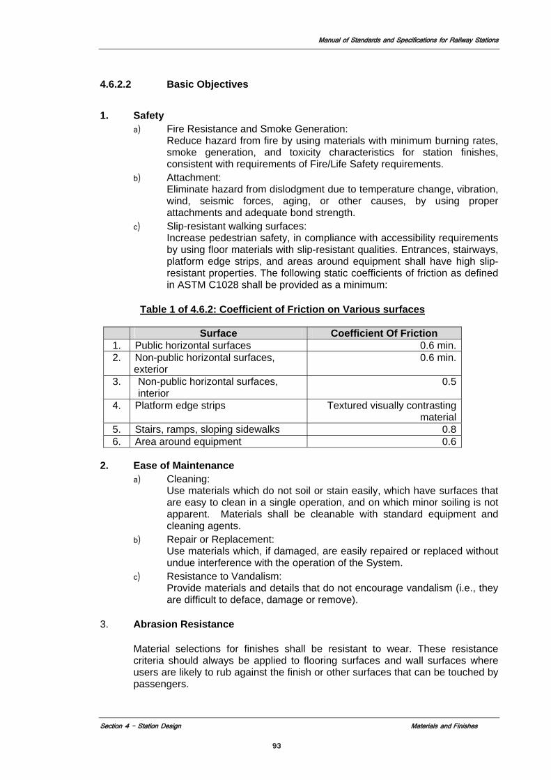
Manual of Standards and Specifications for Railway Stations
Section 4 – Station Design Materials and Finishes
93
4.6.2.2 Basic Objectives
1. Safety
a) Fire Resistance and Smoke Generation: Reduce hazard from fire by using materials with minimum burning rates, smoke generation, and toxicity characteristics for station finishes, consistent with requirements of Fire/Life Safety requirements.
b) Attachment: Eliminate hazard from dislodgment due to temperature change, vibration, wind, seismic forces, aging, or other causes, by using proper attachments and adequate bond strength.
c) Slip-resistant walking surfaces: Increase pedestrian safety, in compliance with accessibility requirements by using floor materials with slip-resistant qualities. Entrances, stairways, platform edge strips, and areas around equipment shall have high slip-resistant properties. The following static coefficients of friction as defined in ASTM C1028 shall be provided as a minimum:
Table 1 of 4.6.2: Coefficient of Friction on Various surfaces
Surface Coefficient Of Friction
1. Public horizontal surfaces 0.6 min.2. Non-public horizontal surfaces,
exterior 0.6 min.
3. Non-public horizontal surfaces, interior
0.5
4. Platform edge strips Textured visually contrasting material
5. Stairs, ramps, sloping sidewalks 0.86. Area around equipment 0.6
2. Ease of Maintenance
a) Cleaning: Use materials which do not soil or stain easily, which have surfaces that are easy to clean in a single operation, and on which minor soiling is not apparent. Materials shall be cleanable with standard equipment and cleaning agents.
b) Repair or Replacement: Use materials which, if damaged, are easily repaired or replaced without undue interference with the operation of the System.
c) Resistance to Vandalism: Provide materials and details that do not encourage vandalism (i.e., they are difficult to deface, damage or remove).
3. Abrasion Resistance
Material selections for finishes shall be resistant to wear. These resistance criteria should always be applied to flooring surfaces and wall surfaces where users are likely to rub against the finish or other surfaces that can be touched by passengers.
Manual of Standards and Specifications for Railway Stations
Section 4 – Station Design Materials and Finishes
94
4. Warning Paver Criteria
Detectable warning edges shall be provided to comply with Indian Disability Act1995 / ADDAG requirements. See section 4.3.2.15
4.6.2.3 Durability
Materials and finishes should comply with the following: 1. Life Cycle
All selected materials shall have a minimum life cycle of 35–50 years.
2. Resistance to Graffiti and Vandalism Provide materials and details that do not encourage vandalism and that are difficult to deface, damage, or remove. All surfaces exposed to direct contact by the public shall be non-porous, strong, and resistant to point loads and scratching so that the results of casual vandalism can be easily removed with normal maintenance techniques. Station designers are required to describe procedures for the removal of more damaging defacement for each finish in public areas and within 3.048 m above the floor surface.
3. Surface Finish
Applied materials shall be hard, dense, non-porous, non-staining, and acid- and alkali-resistant for long life and low maintenance. Surfaces within reach of the public above floor level shall be scratch-resistant or patterned to hide scratches. All finishes shall stand up to wet and freezing conditions, as passengers will track water and snow into the public station areas.
4. Surface Texture
Smooth surfaces are preferred over textured surfaces for ease in cleaning and because they are less prone to catch settling dust. An exception is metal panels, which should be textured to reduce the visual impact of scratches. Textured surfaces are desirable where slip resistance is important, and are acceptable where surfaces are difficult to reach and are therefore unlikely to be cleaned very frequently. A textured surface may hold dust without being visually apparent.
5. Material Expansion
Control joints and expansion joints shall be provided to allow for expansion and contraction; the width and type of joint material shall be designed specifically for each joint. Joint color should coordinate with adjacent material finishes.
6. Fasteners
Fasteners in public areas shall be tamper-resistant and/or concealed. The fastener design must also ensure that the connection of the finish to the substrate is secure so that vibration and movement do not affect the connection.
7. Maintenance
Operations and maintenance are important design considerations in relationship to the materials and material systems that are chosen for the stations.
a) Materials shall be selected for appropriateness, durability, and ease of
maintenance.
Manual of Standards and Specifications for Railway Stations
Section 4 – Station Design Materials and Finishes
95
b) Materials should be easily maintained and vandal-resistant. c) Material elements shall not be painted, or need repainting. d) Manufacturer’s maintenance procedures shall be reviewed prior to the
finalization of the material selection. e) Finish material must be well secured to substrate but easily removable
for replacement. The material, fastening and joint selections shall allow a section of the finish material to be removed and replaced, without damaging or affecting the adjacent portions of the finish surface.
4.6.2.4 Surface Reflectance
Surface reflectance of station materials and finishes is critical to ensuring adequate visual acuity within the stations. Materials and finishes should comply with the following:
1. Energy Conservation
Material selections should appear bright and be light in color in order to facilitate effective lighting, using a minimum number of fixtures.
2. Visual Perception
Brightness is important to the station lighting design, where improving visual acuity and passenger comfort is an objective. The issue of perceived brightness becomes one of the primary factors in visibility and luminance. Lighter surfaces reflect more light, create a brighter station environment and promote improved visual acuity.
3. Natural Light
Station design should incorporate natural light to reduce the need for energy consuming light fixtures.
Surfaces intended to reflect natural light often require additional cleaning; therefore, the selection of materials that comply with the recommended reflectance values must be coordinated and approved by the MOR to ensure maintainability requirements are met.
4.6.2.5 Abrasion Resistance
Abrasion resistance of station finishes and materials is critical to the longevity and maintainability of the stations over time. Floor and wall finishes shall resist wear and tear on materials by having the strength and inherent color to do so. Floor surfaces must resist the abrasion of foot traffic and station designers must consider potential damage from delivery carts’ wheels and cleaning equipment used in the station areas. Floor materials must conform to minimum standards and testing. Finishes shall be chosen with regard to their continual use by pedestrians so that they are resistant to wear and do not show dirt and scratches easily. These surfaces must also be able to resist cleaning materials and cleaning procedures over their lifetime, including typically scrubbing and pressure washing.
4.6.2.6 Chemical Resistance
Station materials and surfaces shall be resistant to chemical decay, including chemicals from cleaning agents, salt, oils, water, dirt, and other foreign substances tracked in by users.
Manual of Standards and Specifications for Railway Stations
Section 4 – Station Design Materials and Finishes
96
4.6.2.7 Low Moisture Absorption
Selected materials shall have low water absorption to help insure the longevity of materials and keep the installation intact. Materials shall resist moisture due to inclement weather and other wet conditions.
4.6.2.8 Light fastness
Lightfastness is defined as the ability of a material to keep its natural color over time. It is important that the materials that are used on the stations are resistant to ultraviolet rays, chemicals, salts, and dirt such that these forces do not dilute or alter the color over the lifetime of the material.
4.6.2.9 Acoustic Considerations
As noted in the Acoustics section, the station’s design will include acoustically absorptive materials. Absorptive materials should be provided to achieve a good aural environment, in which people can communicate clearly and easily and the buildup of excessive noise is suppressed (see Section 4.8.4.1)
4.6.2.10 Appearance
Although stations shall conform to safety, durability, maintenance, cost and sustainability criteria, the following considerations are important for the ultimate success of the stations.
4.6.2.11 Architectural Character
In stations, station geometry and finishes are the primary elements that help define the architectural character of the station, which would result in a high level of illumination, good cleanliness levels, and the appearance of high cleanliness. The finish material selections should be attractive and of the highest quality. The aesthetic qualities of the system shall be designed in order to instill civic pride.
Applied materials shall be hard, dense, non-porous, non-staining, acid and alkali resistant, for long life and low maintenance. Surfaces within reach of the public, up to 3 meters above the floor level may be finished with applied materials.
Colours shall contribute to high illumination levels, with sufficient contrasts and accents to provide visual interest, warmth, and to conceal minor soiling. In all Stations a 100 mm wide yellow tile, acting as a passenger warning strip shall be placed adjacent to the platform edge.
Smooth surfaces are preferred over rough ones for ease in cleaning and because they are less prone to catch settling dust. Rough surfaces are desirable where a slip-resistant feature is important, and are acceptable where surfaces are difficult to reach and are therefore unlikely to be cleaned very frequently.
Unit size shall be large enough to reduce the number of joints yet small enough to conceal minor soiling and scratches and to facilitate replacement if damaged. Monolithic materials may be used in plant room areas providing they are laid in bays not exceeding 16 metres square and incorporating brass or equivalent separating strips.
To minimise maintenance problems, joints shall be small, flush, limited in number and of
the best possible materials. Horizontal joints shall not be raked but shall be flush or
Manual of Standards and Specifications for Railway Stations
Section 4 – Station Design Materials and Finishes
97
tooled concave. Monolithic materials shall have adequate control joints and expansion joints at the proper spacing in order to prevent surface cracking.
Materials shall be selected for long life, low maintenance, replacement considerations
and overall aesthetic and functional qualities. Materials shall be selected which are readily available. Domestic products shall be
selected unless the product is not available within the country. Materials shall be detailed and specified to be installed in accordance with industry
standards and manufacturer’s printed directions. Interior finishes shall meet requirements of the Code and the Fire/Life Safety Requirement.
1. Finishes for all protected exit ways shall be Class A as defined by NFPA 101. In
underground stations, platforms, mezzanines, corridors, stairways, and vestibules shall be considered exit ways.
2. Finishes in all other areas shall be Class B as defined by NFPA 101. 3. Combustible adhesives and sealant may be used when they meet the
requirements stated above.
Materials shall contain no known carcinogens, have low levels of volatile organic contaminants and should not utilize chlorofluorocarbons (CFCs) during production.
Materials shall have a low embodied energy rating; this includes the quantity of energy required by all of the activities associated with production, acquisition, transportation, manufacturing and handling of a particular product (see section 5.2).
4.6.2.12 Elements of Continuity
Elements of continuity shall link the stations and the system together. These elements of continuity can include any number of architectural elements that are repeated throughout the system (see Section 4.4.2). Color may be used to unify system lines and to create station identity. Specific color criteria shall be developed and approved by MOR.
4.6.2.13 Modular Units
The station designer shall develop a module as a tool to help unify station elements and finishes and achieve a visually coordinated design (see Section 4.4). The module should not necessarily be visible in the wall, floor and ceiling finishes but should used as an organizing principle for the planning and layout of all station elements, including base, handrails, guardrails, signage, lighting, advertising, etc.
4.6.2.14 Elements of Variability
Elements of variability respond to and reflect local or special context, introduce variations in design and finishes for unique locations. Acceptable materials and corresponding finishes shall respond to the unique context of the station location.
4.6.3 Specific Requirements
The surfaces in the station, including floors, walls, ceilings, and other miscellaneous surfaces and objects in public areas, must comply with specific criteria in order for the stations to be safe, well lit and acoustically comfortable, of high quality, and that will
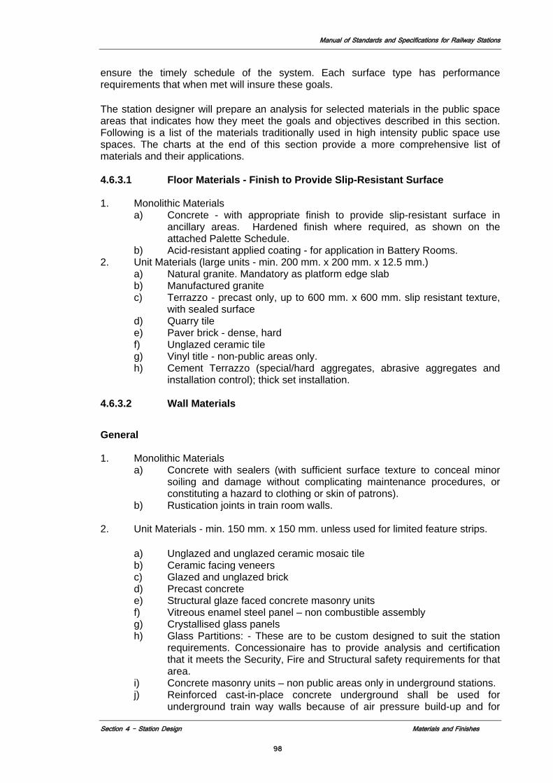
Manual of Standards and Specifications for Railway Stations
Section 4 – Station Design Materials and Finishes
98
ensure the timely schedule of the system. Each surface type has performance requirements that when met will insure these goals.
The station designer will prepare an analysis for selected materials in the public space areas that indicates how they meet the goals and objectives described in this section. Following is a list of the materials traditionally used in high intensity public space use spaces. The charts at the end of this section provide a more comprehensive list of materials and their applications.
4.6.3.1 Floor Materials - Finish to Provide Slip-Resistant Surface
1. Monolithic Materials a) Concrete - with appropriate finish to provide slip-resistant surface in
ancillary areas. Hardened finish where required, as shown on the attached Palette Schedule.
b) Acid-resistant applied coating - for application in Battery Rooms. 2. Unit Materials (large units - min. 200 mm. x 200 mm. x 12.5 mm.)
a) Natural granite. Mandatory as platform edge slab b) Manufactured granite c) Terrazzo - precast only, up to 600 mm. x 600 mm. slip resistant texture,
with sealed surface d) Quarry tile e) Paver brick - dense, hard f) Unglazed ceramic tile g) Vinyl title - non-public areas only. h) Cement Terrazzo (special/hard aggregates, abrasive aggregates and
installation control); thick set installation. 4.6.3.2 Wall Materials
General
1. Monolithic Materials a) Concrete with sealers (with sufficient surface texture to conceal minor
soiling and damage without complicating maintenance procedures, or constituting a hazard to clothing or skin of patrons).
b) Rustication joints in train room walls.
2. Unit Materials - min. 150 mm. x 150 mm. unless used for limited feature strips.
a) Unglazed and unglazed ceramic mosaic tile b) Ceramic facing veneers c) Glazed and unglazed brick d) Precast concrete e) Structural glaze faced concrete masonry units f) Vitreous enamel steel panel – non combustible assembly g) Crystallised glass panels h) Glass Partitions: - These are to be custom designed to suit the station
requirements. Concessionaire has to provide analysis and certification that it meets the Security, Fire and Structural safety requirements for that area.
i) Concrete masonry units – non public areas only in underground stations. j) Reinforced cast-in-place concrete underground shall be used for
underground train way walls because of air pressure build-up and for
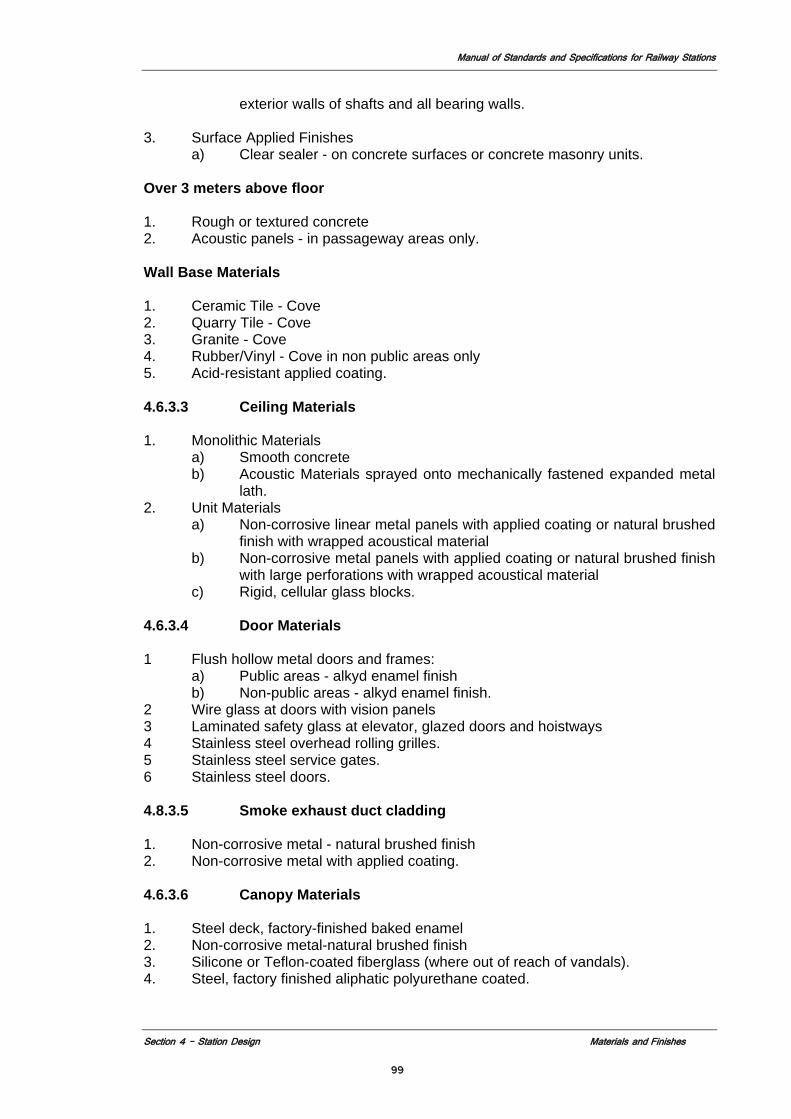
Manual of Standards and Specifications for Railway Stations
Section 4 – Station Design Materials and Finishes
99
exterior walls of shafts and all bearing walls.
3. Surface Applied Finishes a) Clear sealer - on concrete surfaces or concrete masonry units.
Over 3 meters above floor 1. Rough or textured concrete 2. Acoustic panels - in passageway areas only.
Wall Base Materials 1. Ceramic Tile - Cove 2. Quarry Tile - Cove 3. Granite - Cove 4. Rubber/Vinyl - Cove in non public areas only 5. Acid-resistant applied coating.
4.6.3.3 Ceiling Materials
1. Monolithic Materials a) Smooth concrete b) Acoustic Materials sprayed onto mechanically fastened expanded metal
lath. 2. Unit Materials
a) Non-corrosive linear metal panels with applied coating or natural brushed finish with wrapped acoustical material
b) Non-corrosive metal panels with applied coating or natural brushed finish with large perforations with wrapped acoustical material
c) Rigid, cellular glass blocks. 4.6.3.4 Door Materials
1 Flush hollow metal doors and frames: a) Public areas - alkyd enamel finish b) Non-public areas - alkyd enamel finish.
2 Wire glass at doors with vision panels 3 Laminated safety glass at elevator, glazed doors and hoistways 4 Stainless steel overhead rolling grilles. 5 Stainless steel service gates. 6 Stainless steel doors.
4.8.3.5 Smoke exhaust duct cladding
1. Non-corrosive metal - natural brushed finish 2. Non-corrosive metal with applied coating.
4.6.3.6 Canopy Materials
1. Steel deck, factory-finished baked enamel 2. Non-corrosive metal-natural brushed finish 3. Silicone or Teflon-coated fiberglass (where out of reach of vandals). 4. Steel, factory finished aliphatic polyurethane coated.
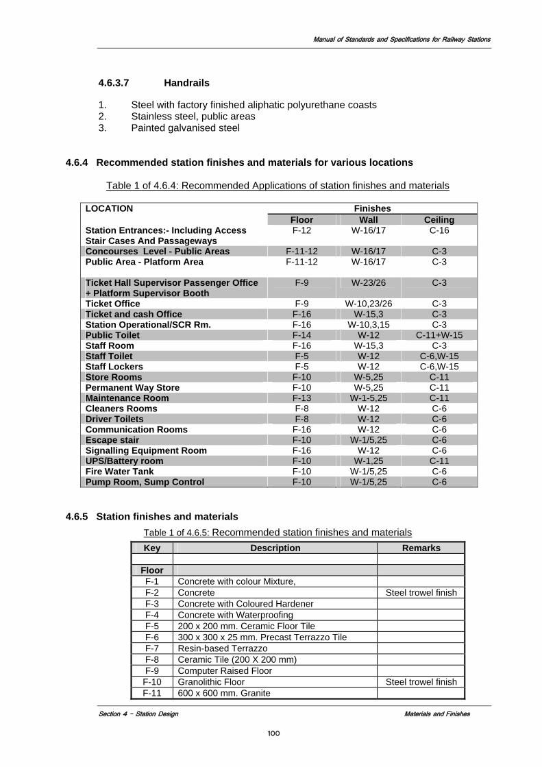
Manual of Standards and Specifications for Railway Stations
Section 4 – Station Design Materials and Finishes
100
4.6.3.7 Handrails
1. Steel with factory finished aliphatic polyurethane coasts 2. Stainless steel, public areas 3. Painted galvanised steel
4.6.4 Recommended station finishes and materials for various locations
Table 1 of 4.6.4: Recommended Applications of station finishes and materials
LOCATION Finishes Floor Wall Ceiling
Station Entrances:- Including Access Stair Cases And Passageways
F-12 W-16/17 C-16
Concourses Level - Public Areas F-11-12 W-16/17 C-3 Public Area - Platform Area F-11-12 W-16/17
C-3
Ticket Hall Supervisor Passenger Office + Platform Supervisor Booth
F-9 W-23/26 C-3
Ticket Office F-9 W-10,23/26 C-3 Ticket and cash Office F-16 W-15,3 C-3 Station Operational/SCR Rm. F-16 W-10,3,15 C-3 Public Toilet F-14 W-12 C-11+W-15 Staff Room F-16 W-15,3 C-3 Staff Toilet F-5 W-12 C-6,W-15 Staff Lockers F-5 W-12 C-6,W-15 Store Rooms F-10 W-5,25 C-11 Permanent Way Store F-10 W-5,25 C-11 Maintenance Room F-13 W-1-5,25 C-11 Cleaners Rooms F-8 W-12 C-6 Driver Toilets F-8 W-12 C-6 Communication Rooms F-16 W-12 C-6 Escape stair F-10 W-1/5,25 C-6 Signalling Equipment Room F-16 W-12 C-6 UPS/Battery room F-10 W-1,25 C-11 Fire Water Tank F-10 W-1/5,25 C-6 Pump Room, Sump Control F-10 W-1/5,25 C-6
4.6.5 Station finishes and materials
Table 1 of 4.6.5: Recommended station finishes and materials Key Description Remarks
Floor F-1 Concrete with colour Mixture, F-2 Concrete Steel trowel finish F-3 Concrete with Coloured Hardener F-4 Concrete with Waterproofing F-5 200 x 200 mm. Ceramic Floor Tile F-6 300 x 300 x 25 mm. Precast Terrazzo Tile F-7 Resin-based Terrazzo F-8 Ceramic Tile (200 X 200 mm) F-9 Computer Raised Floor F-10 Granolithic Floor Steel trowel finish F-11 600 x 600 mm. Granite
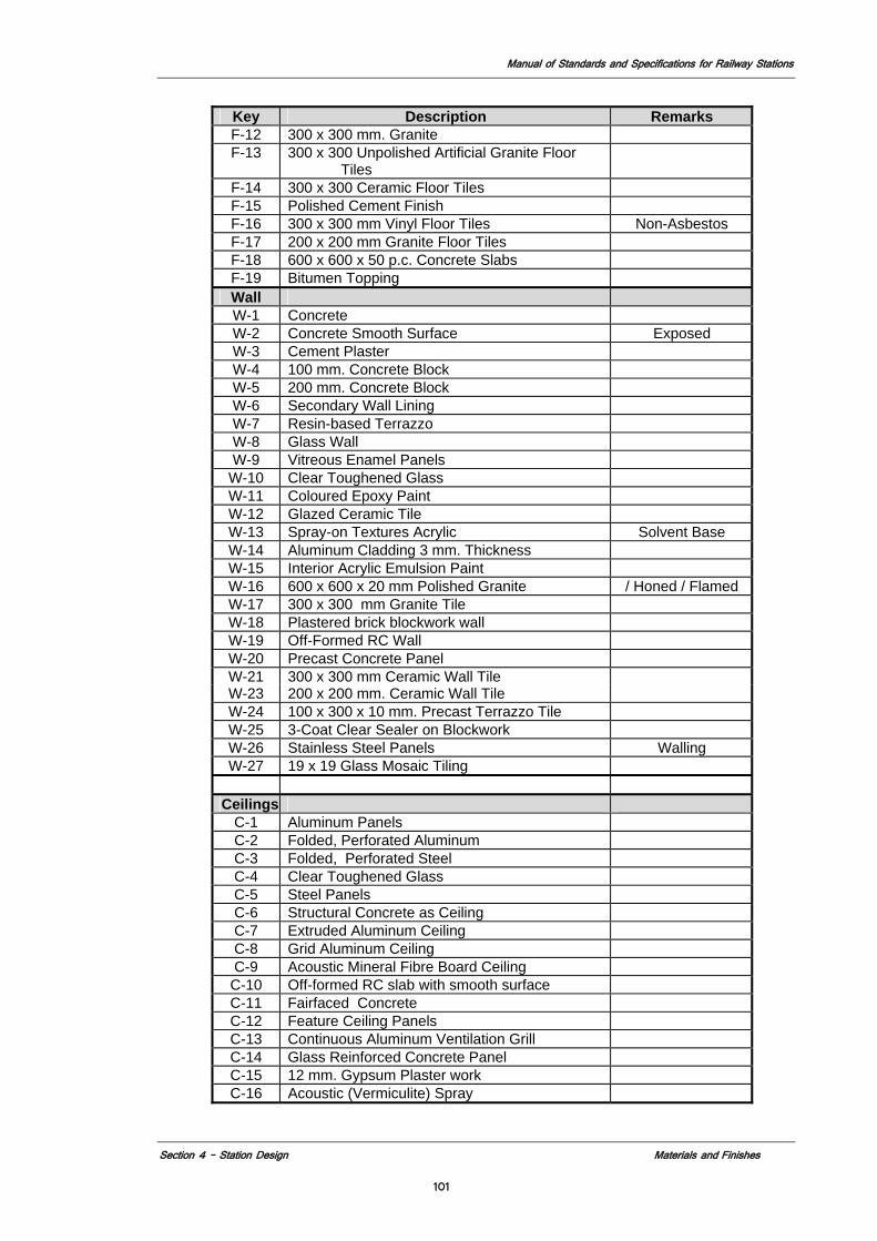
Manual of Standards and Specifications for Railway Stations
Section 4 – Station Design Materials and Finishes
101
Key Description Remarks F-12 300 x 300 mm. Granite F-13 300 x 300 Unpolished Artificial Granite Floor
Tiles
F-14 300 x 300 Ceramic Floor Tiles F-15 Polished Cement Finish F-16 300 x 300 mm Vinyl Floor Tiles Non-Asbestos F-17 200 x 200 mm Granite Floor Tiles F-18 600 x 600 x 50 p.c. Concrete Slabs F-19 Bitumen Topping Wall W-1 Concrete W-2 Concrete Smooth Surface Exposed W-3 Cement Plaster W-4 100 mm. Concrete Block W-5 200 mm. Concrete Block W-6 Secondary Wall Lining W-7 Resin-based Terrazzo W-8 Glass Wall W-9 Vitreous Enamel Panels
W-10 Clear Toughened Glass W-11 Coloured Epoxy Paint W-12 Glazed Ceramic Tile W-13 Spray-on Textures Acrylic Solvent Base W-14 Aluminum Cladding 3 mm. Thickness W-15 Interior Acrylic Emulsion Paint W-16 600 x 600 x 20 mm Polished Granite / Honed / Flamed W-17 300 x 300 mm Granite Tile W-18 Plastered brick blockwork wall W-19 Off-Formed RC Wall W-20 Precast Concrete Panel W-21 300 x 300 mm Ceramic Wall Tile W-23 200 x 200 mm. Ceramic Wall Tile W-24 100 x 300 x 10 mm. Precast Terrazzo Tile W-25 3-Coat Clear Sealer on Blockwork W-26 Stainless Steel Panels Walling W-27 19 x 19 Glass Mosaic Tiling
Ceilings
C-1 Aluminum Panels C-2 Folded, Perforated Aluminum C-3 Folded, Perforated Steel C-4 Clear Toughened Glass C-5 Steel Panels C-6 Structural Concrete as Ceiling C-7 Extruded Aluminum Ceiling C-8 Grid Aluminum Ceiling C-9 Acoustic Mineral Fibre Board Ceiling C-10 Off-formed RC slab with smooth surface C-11 Fairfaced Concrete C-12 Feature Ceiling Panels C-13 Continuous Aluminum Ventilation Grill C-14 Glass Reinforced Concrete Panel C-15 12 mm. Gypsum Plaster work C-16 Acoustic (Vermiculite) Spray
Manual of Standards and Specifications for Railway Stations
Section 4 – Station Design Lighting
102
4.7 LIGHTING
4.7.1 Introduction
Lighting is an integral part of station architecture and as such should respond to the given architectural conditions and be coordinated with other elements of the stations. In addition to providing illumination and a sense of security, the lighting system in railway stations should be durable, energy efficient and easily maintained. The lighting in office rooms, passages, stairs, open areas etc. shall be provided as per established norms and appropriately positioned. The station designer shall prepare an analysis as called for in section 4.7.4.2 that demonstrates how the standards, goal and objectives for the lighting of the stations called for in this manual are met by the design. Codes and Standards The design of lighting systems will utilize the latest editions of all appropriate and applicable reference standards, regulations and codes as follows:
National Building Code, India Energy Conservation and Building Code, India British Standard EN 12464 (UK) ADA Accessibility Guidelines (ADAAG), USA American National Standards Institute (ANSI) American Society for Testing and Materials (ASTM) TERI (The Energy and Resource Institute) Recommendations and Mandates Green building Council (GBC), USA Leadership in Energy & Environmental Design (LEED), USA National Fire Protection Association (NFPA), USA Toxicity Characteristic Leaching Procedure (TCLP) American Public Transportation Association (APTA) American Society of Heating, Refrigerating and Air-Conditioning Engineers (ASHRAE) Illuminating Engineering Society of North America (IESNA)
4.7.2 Scope
The scope for station lighting includes, but is not limited to, lighting equipment, illumination levels, and control systems for the station in the following areas: 1. Station Site 2. Platform 3. Station Building
a) Concourse b) Circulation c) Waiting d) Interactive Areas e) Service Areas
4.7.3 Lighting Design Requirements
Lighting design shall provide an appropriate transition from street to station. Concepts for lighting design are set forth under the umbrella principles of Safety, Economy and Drama: 1. Integration with architecture and artwork 2. Emphasis at key points of transition and transaction 3. Promotion of the sense of real and perceived security
Manual of Standards and Specifications for Railway Stations
Section 4 – Station Design Lighting
103
4. Control of lighting in public areas via station management system 5. Location of luminaires and system components for feasible maintenance; 6. Introduction of natural light into station volumes wherever feasible 7. Intelligent systems /concepts shall be used for automatic switching on and off of
the lighting fixtures. Sensors shall operate as per the lighting levels in different weather conditions. It will be focused to achieve maximum energy savings.
4.7.3.1 Station Site
1. Adequate lighting levels shall be provided in parking lots and at access points to
the station entrances. Lighting shall not interfere with or blind train operations. 2. Lighting fixtures at site and parking shall be of consistent design and evenly
spaced. 3. Station façade shall be lighted to ensure the most effective esthetic presentation
of the station building features. In addition all entrances shall have adequate lighting to ensure adequate identification of access and egress points to the building.
4. All exterior signs must maintain an acceptable level of lighting for clear visibility up to 150m away. If general lighting is not appropriate for any specific sign the sign shall have dedicated light fixtures mounted on sign structure or independently mounted directly adjacent to the sign lighting requirements.
5. Site lighting shall be electric photocell controlled.
4.7.3.2 Platform and Track Area
1. Platform fixtures shall be post mounted when platform is uncovered. Canopy or enclosed platform fixtures shall be surface or pendent mounted at a consistent height throughout the platform.
2. Lamps for platform and canopy fixtures shall be identical to maintain uniform illumination throughout platform area.
3. Platform lighting shall highlight the platform edge. 4. Lighting at exterior platform and canopies shall be high pressure sodium. 4.7.3.3 Platform Access
Where platform and site lighting is not adequate for platform access pathways, ramps, VCEs, underpasses and overpasses (foot over bridge), separate light fixtures shall be provided with adequate lighting for way finding and to provide an acceptable level of security. 4.7.3.4 Station Building Station Building Interior lighting should facilitate passenger orientation, identification of systems graphics, and definition of circulation patterns within the building. 1. Additional lighting is required at ticketing, administrative areas/ offices, utility
areas, and waiting areas. 2. Backlit exit signs must be provided at all exits. 3. Emergency lighting shall be provided at all facilities. 4. Lighting at station building shall comply with applicable codes and standards. 5. Fluorescent fixtures shall have high frequency, energy saving, solid state
electronic ballast. 6. Color improved fluorescent lamps shall be used to provide a superior quality
lighting environment rendering all lighted surfaces true to color.
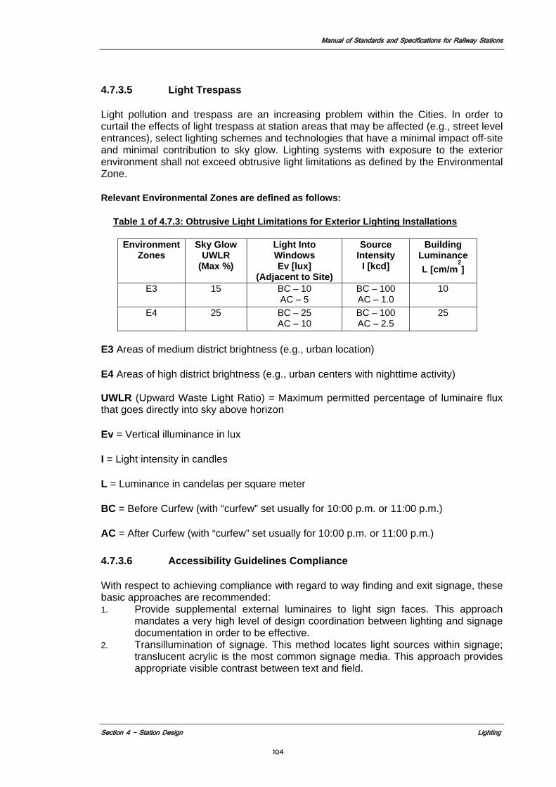
Manual of Standards and Specifications for Railway Stations
Section 4 – Station Design Lighting
104
4.7.3.5 Light Trespass
Light pollution and trespass are an increasing problem within the Cities. In order to curtail the effects of light trespass at station areas that may be affected (e.g., street level entrances), select lighting schemes and technologies that have a minimal impact off-site and minimal contribution to sky glow. Lighting systems with exposure to the exterior environment shall not exceed obtrusive light limitations as defined by the Environmental Zone.
Relevant Environmental Zones are defined as follows:
Table 1 of 4.7.3: Obtrusive Light Limitations for Exterior Lighting Installations
Environment
Zones Sky Glow
UWLR (Max %)
Light Into Windows Ev [lux]
(Adjacent to Site)
Source Intensity
I [kcd]
Building Luminance L [cm/m
2]
E3 15 BC – 10 AC – 5
BC – 100 AC – 1.0
10
E4 25 BC – 25 AC – 10
BC – 100 AC – 2.5
25
E3 Areas of medium district brightness (e.g., urban location)
E4 Areas of high district brightness (e.g., urban centers with nighttime activity) UWLR (Upward Waste Light Ratio) = Maximum permitted percentage of luminaire flux that goes directly into sky above horizon
Ev = Vertical illuminance in lux
I = Light intensity in candles
L = Luminance in candelas per square meter
BC = Before Curfew (with “curfew” set usually for 10:00 p.m. or 11:00 p.m.)
AC = After Curfew (with “curfew” set usually for 10:00 p.m. or 11:00 p.m.)
4.7.3.6 Accessibility Guidelines Compliance
With respect to achieving compliance with regard to way finding and exit signage, these basic approaches are recommended: 1. Provide supplemental external luminaires to light sign faces. This approach
mandates a very high level of design coordination between lighting and signage documentation in order to be effective.
2. Transillumination of signage. This method locates light sources within signage; translucent acrylic is the most common signage media. This approach provides appropriate visible contrast between text and field.
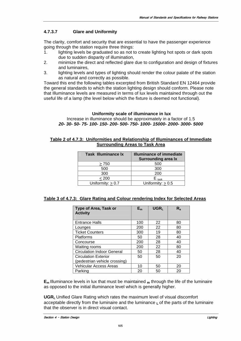
Manual of Standards and Specifications for Railway Stations
Section 4 – Station Design Lighting
105
4.7.3.7 Glare and Uniformity
The clarity, comfort and security that are essential to have the passenger experience going through the station require three things: 1. lighting levels be graduated so as not to create lighting hot spots or dark spots
due to sudden disparity of illumination, 2. minimize the direct and reflected glare due to configuration and design of fixtures
and luminaires, 3. lighting levels and types of lighting should render the colour palate of the station
as natural and correctly as possible. Toward this end the following tables excerpted from British Standard EN 12464 provide the general standards to which the station lighting design should conform. Please note that Illuminance levels are measured in terms of lux levels maintained through out the useful life of a lamp (the level below which the fixture is deemed not functional).
Uniformity scale of illuminance in lux Increase in illuminance should be approximately in a factor of 1.5
20- 30- 50- 75- 100- 150- 200- 500- 750- 1000- 15000- 2000- 3000- 5000
Table 2 of 4.7.3: Uniformities and Relationship of Illuminances of Immediate
Surrounding Areas to Task Area
Task Illuminance lx Illuminance of immediate Surrounding area lx
> 750 500 500 300 300 200
< 200 E taskUniformity: > 0.7 Uniformity: > 0.5
Table 3 of 4.7.3: Glare Rating and Colour rendering Index for Selected Areas
Type of Area, Task or Activity
Em UGRL Ra
Entrance Halls 100 22 80 Lounges 200 22 80 Ticket Counters 300 19 80 Platforms 50 28 40 Concourse 200 28 40 Waiting rooms 200 22 80 Circulation Indoor General 50 28 40 Circulation Exterior (pedestrian vehicle crossing)
50 50 20
Vehicular Access Areas 10 50 20 Parking 20 50 20
Em Illuminance levels in lux that must be maintained m through the life of the luminaire as opposed to the initial illuminance level which is generally higher. UGRL Unified Glare Rating which rates the maximum level of visual discomfort acceptable directly from the luminaire and the luminance L of the parts of the luminaire that the observer is in direct visual contact.
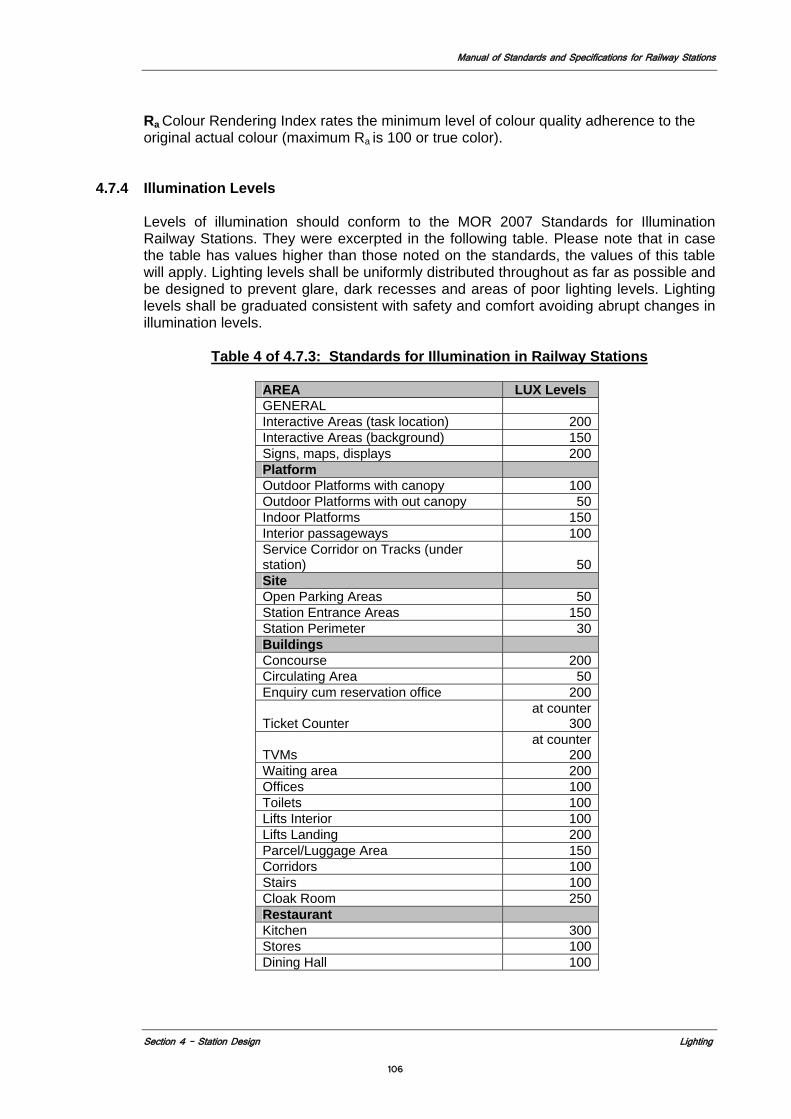
Manual of Standards and Specifications for Railway Stations
Section 4 – Station Design Lighting
106
Ra Colour Rendering Index rates the minimum level of colour quality adherence to the original actual colour (maximum Ra is 100 or true color).
4.7.4 Illumination Levels
Levels of illumination should conform to the MOR 2007 Standards for Illumination Railway Stations. They were excerpted in the following table. Please note that in case the table has values higher than those noted on the standards, the values of this table will apply. Lighting levels shall be uniformly distributed throughout as far as possible and be designed to prevent glare, dark recesses and areas of poor lighting levels. Lighting levels shall be graduated consistent with safety and comfort avoiding abrupt changes in illumination levels.
Table 4 of 4.7.3: Standards for Illumination in Railway Stations
AREA LUX Levels GENERAL Interactive Areas (task location) 200 Interactive Areas (background) 150 Signs, maps, displays 200 Platform Outdoor Platforms with canopy 100 Outdoor Platforms with out canopy 50 Indoor Platforms 150 Interior passageways 100 Service Corridor on Tracks (under station) 50 Site Open Parking Areas 50 Station Entrance Areas 150 Station Perimeter 30 Buildings Concourse 200 Circulating Area 50 Enquiry cum reservation office 200
Ticket Counter at counter
300
TVMs at counter
200 Waiting area 200 Offices 100 Toilets 100 Lifts Interior 100 Lifts Landing 200 Parcel/Luggage Area 150 Corridors 100 Stairs 100 Cloak Room 250 Restaurant Kitchen 300 Stores 100 Dining Hall 100
Manual of Standards and Specifications for Railway Stations
Section 4 – Station Design Lighting
107
4.7.4.1 Fixture Location Parameters
Specific strategies for lighting system location include: 1. Lighting system components must be located such that they may be feasibly
maintained. Lighting equipment located over VCEs and other open areas shall not be placed directly over such openings, and should be either very long life (5–10 years average rated life), remote-source, or located at a height so as to preclude the need for scaffolding.
2. All light fixtures and equipment shall be located not less than .916m inward from the platform edge.
3. A maximum mounting height of 3.201 m above finished floor (AFF) at the platform level is recommended. Maximum mounting height of luminaires and system components should be determined by station architecture in conjunction with feasibility of system component maintenance. Light source average rated life should be factored into this equation.
4. Minimum mounting height shall be not less than 2.591 m AFF in all station areas except where existing architecture may interfere. In such cases, fixtures must be located not lower than 2.030 m AFF.
5. Fixtures located below 2.134 m AFF must comply with the ADAAG requirements, and be vandal-resistant.
6. Under no circumstances should cooled air pass directly over unlensed linear fluorescent sources, as such cooling will cause lamp discoloration and reduced lumen output.
7. Luminaires should be located in such a manner so as to maximize public safety and minimize the potential for deliberate vandalism or inadvertent damage by other station systems or equipment
8. Maintenance of light sources via a group-re-lamping strategy should be considered. This approach helps to control costs as well as minimize the disruption of any stations’ normal operations.
9. The colour and appearance of the lamps should be natural for the application and complement the interior colour scheme, which should be chosen with an appreciation of the reflectance values that will be achieved. Lamps should be selected with appropriate colour rendition properties, for colour discrimination and reduction of eye fatigue.
4.7.4.2 Calculation Requirements
Provide lighting calculations for both normal and emergency lighting systems and submit computer generated analysis with photometric data for all luminaires utilized showing illumination level in lux for all public and key nonpublic (utility) areas, indicating compliance with illuminance criteria as set forth in this section. All calculations shall consider all engineering data, such as coefficient of utilization (CU) and light loss factor (LLF). For the lighting analysis refer to the British Standard EN 12464-1:2002 for indoor and British Standard EN 12464-2:2007 for outdoor. Calculations shall also show the reduction in the luminaire use and resultant energy savings due the natural light provided by the design during the daylight hours as required in 4.7.7.2. Computer generated lighting calculation analyses developed for stations should at minimum display the following data: 1. Fixture location, in context with station architecture 2. Horizontal average illuminance (maintained); points to be located on .636 m
centers or less 3. Vertical wall average illuminance (maintained) 4. Average/minimum and maximum/minimum ratios (uniformity) 5. LPD analysis for all relevant station areas
Manual of Standards and Specifications for Railway Stations
Section 4 – Station Design Lighting
108
6. Statistical data regarding type of luminaire used 7. Statistical data regarding type of lamp/lumens 8. Complete independent laboratory photometric test data for each fixture type,
including lumen distribution curve 9. Part plan design drawings for all calculation areas, and sections/elevations
showing relative location of the fixtures and associated components 10. Three-dimensional image of the calculation environment.
4.7.4.3 Luminaries
Luminaires are to be selected based on specific criteria required by each selected fixture and the overall lighting plan developed for the station which involves the above mentioned analysis. In general the luminaries used in the station should conform to the following list and any subsequent update issued by MOR. If the lighting plan developed stipulates that for specific fixture another luminaire is called for it should note why it is used in place of the ones called for on the MOR list. For platform and throughout other rail road areas the luminaries should be fitted with “cool white light” types of lamps. 1. T-5 for Interior spaces 2. Compact Fluorescent Lamp 3. Metal Halide for exterior areas Luminaires shall have the following degree of protection 1. Open areas > IP 67 2. Enclosed spaces > IP 66
4.7.4.4 Coordination Requirements
1. Central Management The station shall have a dedicated central management unit of all major E&M equipment so that the maintenance staff can have control over them (Building management system as per NBC 2005). The equipment under central command shall include lighting and control operation shall be programmed to maximize energy efficiency (see section 5.5.5). At platform level lighting shall be at 100% only with the arrival of the trains. At other times lighting level shall be reduced to a suitable level.
2. Systems Coordination
Lighting system shall be coordinated with communication, signage, life safety, ventilation/environmental control and any other applicable engineering disciplines. Lighting layouts for all areas shall be coordinated with the structural system and architectural design of the station.
3. Environmental
Lighting fixtures plan shall promote sustainability goals of encouraging clean energy sources, on site energy production and maximizing day lighting (see section 5.2.2.6)
4.7.5 Lighting Systems
4.7.5.1 Lighting System Fixture Parameters
The lighting system shall include, but not be limited to, the following array of components: 1. Normal lighting (powered via normal and reserve circuits) 2. Emergency lighting (designated luminaire[s] on emergency circuit[s])
Manual of Standards and Specifications for Railway Stations
Section 4 – Station Design Lighting
109
3. Point source fixtures for use as either general distribution or accent, fixed or adjustable
4. Public address (PA) speakers (unless integration will compromise performance requirements as noted in the Communications section)
5. Way finding signage, transilluminated or screened 6. Station identification signage, transilluminated or screened 7. Dynamic signage, such as variable messaging system (VMS) in the customer
information sign (CIS) 8. Surveillance 9. Strobe (fire alert) 10. Train annunciation 11. Integrated wireway management of related systems components. Wireway
and/or conduit will be hidden from view in accordance with the parameters set forth in the Utility and Systems Interface section.
4.7.5.2 Integrated Lighting System
Lighting will be delivered via a unified system encompassing wireway management and multiple services for all public areas. The lighting system shall be capable of responding to the various conditions that will be found in all station configurations as they are developed. 1. Luminaires, whether part of an integrated system or standalone, must be durable
and suitable for a minimum 50-year life cycle. This standard of durability shall include the ability for luminaires and components to withstand seismic vibration, moisture, steel dust and the potential for vandalism, and operate within a temperature range of -10 to 50° Celsius.
2. The predominant lighting in station public areas will be delivered via a lighting system, integrating normal and emergency lighting and other areas/objects requiring power.
3. Individual component units shall allow for ease of maintenance, future replacement and expandability and tool less access for basic tasks.
4.7.5.3 Non-Integrated Lighting
In all cases where a non-integrated approach is proposed, light fixtures shall utilize approved family of light sources and must demonstrate adherence to principles outlined in this section, 4.7.5.4 Support (Utility) Areas Lighting
Support areas are those in which more task-oriented activities may occur, and as such lighting must be provided and located accordingly. 4.7.5.5 Emergency Lighting
Emergency lighting shall conform to all applicable provisions of NFPA 130 (1 foot-candle average, 40 to 1 max. to min. ratio). In stations where emergency power is provided by an independent alternating current (AC) source, such as an uninterruptible power supply (UPS) system, emergency lighting shall be supplied by a percentage of normally energized luminaires. In the event of power failure, emergency lighting shall define a path of egress to assist in safe and orderly evacuation.
Manual of Standards and Specifications for Railway Stations
Section 4 – Station Design Lighting
110
All public areas of the station, including stairs, passageways and entry require emergency lighting. Emergency lighting for stairs and escalators should emphasize illumination on the top and bottom steps and landings. Electrical and mechanical equipment rooms shall be provided with emergency lighting to enable safe evacuation and troubleshooting. Exit signage shall be provided with sufficient illumination for way finding during normal power failure. Transilluminated exit signage shall be fed via emergency circuit. Should exit signage not be transilluminated, sufficient vertical illuminance shall be provided on the sign face to provide for readability in the event of normal power failure. See section 5.5.5.
4.7.6 Lighting Controls
Stations operate on a 24-hour, 7-day-per-week basis. The designer utilizes a station-management system to provide for lighting control in all public areas (see section 5.2.2). Service areas shall be provided with lighting control either via local switching, occupancy sensor or as part of the station-management control system. Appropriate control systems may take the form of relays or programmable breakers. Interface with other station management systems is common in similar installations, as is integration with photocells and astronomical time clocks. Regardless of control philosophy, the control system must allow for the maintenance of safe minimum light levels at all times. Nonpublic areas should be controlled via occupancy sensors with local switch override wherever feasible.
4.7.7 Design for the Environmental Strategies
Specific sustainability goals that have particular relevance for station lighting design are: 1. Encourage Clean Energy Sources 2. Maximize Day lighting 3. Encourage On-site Energy Production
4.7.7.1 Respond to Demand: Lighting
1. Utilize energy efficient technologies. Lighting control strategies for station areas
will assist in the reduction of energy consumption as well. 2. Use activity sensors to activate the lighting system when it is needed in
nonpublic areas. 3. Minimize Thermal Pollution.
4.7.7.2 Increase Natural Light
Wherever feasible the use of daylight is recommended. When utilized in conjunction with responsive control technology, natural light may provide sufficient illumination to warrant de-energization of designated electrical lighting, offering potential energy savings. As a side benefit, natural light can increase customers’ positive sense of station orientation and identification.
Supplementing artificial lighting with natural daylight can be achieved with use of glass and through openings in the structure, directly focusing the light from open areas to remote areas, and through fiber optic lighting that uses daylight directly.
Manual of Standards and Specifications for Railway Stations
Section 4 – Station Design Lighting
111
Concessionaire shall demonstrate the percentage savings resulting from the use of natural light to supplement artificial light in different areas of the station during the light hours separately for different times during the day.
Manual of Standards and Specifications for Railway Stations
Section 4 – Station Design Acoustics 112
4.8 ACOUSTICS
4.8.1 Introduction Acoustics of an environment has the ability to affect the way people behave. Excessive
noise and poor speech intelligibility may lead to frustration on the part of the passengers in a confined area, such as the station building. The acoustic design of stations must provide a good aural environment, in which people can communicate clearly and easily, and the build-up of excessive noise is suppressed. Public address (PA) announcements must be easily heard and understood. A comfortable acoustic environment must also be provided for the employees in the nonpublic areas, such as in offices and administration areas. The concessionaire must provide documentation that the station’s design achieves these goals.
The criteria established here addresses achieving intelligible speech communication (face-to-face, telephone, public address, and intercom).
References The latest editions of the following reference standards, regulations, and codes will be utilized: Noise Pollution, Regulation and Control Rules, 2000 (India)
The International Organization for Standardization (ISO) NFPA 72 - National Fire Alarm Code (USA) International Electro-technical Commission (IEC) 60849: 1998- Sound Systems for Emergency Purposes, for speech intelligibility requirements.
4.8.2 Acoustics Evaluation Noise Sources The noise levels perceived on the Station and the platforms will vary considerably during the normal operating day. In the short term, there will be increase in noise with the movement of trains. In the longer term, there will be changes in occupational noise level with the changes in passenger loadings on the platforms.
1. Train Noise: (Noise from a stationary train at a platform).
a) Train motor idling b) Train air conditioners. c) Generator cars.
2 Structural Noise
a) Rail sources b) Use of lightweight structures c) Resilience of the track form d) Heating, Ventilation and Air Conditioning equipment e) Station machinery f) Equipment above grade (affecting adjacent structures) including Backup
generators.
4.8.3 Acoustical Environment The acoustical environment within the stations shall provide a good aural environment, where people can communicate clearly and easily and the buildup of excessive noise is suppressed. Controlling the buildup of noise and ensuring good speech intelligibility are
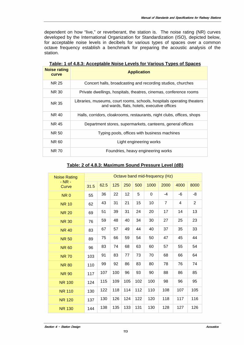
Manual of Standards and Specifications for Railway Stations
Section 4 – Station Design Acoustics 113
dependent on how “live,” or reverberant, the station is. The noise rating (NR) curves developed by the International Organization for Standardization (ISO), depicted below, for acceptable noise levels in decibels for various types of spaces over a common octave frequency establish a benchmark for preparing the acoustic analysis of the station.
Table: 1 of 4.8.3: Acceptable Noise Levels for Various Types of Spaces
Noise rating curve Application
NR 25 Concert halls, broadcasting and recording studios, churches
NR 30 Private dwellings, hospitals, theatres, cinemas, conference rooms
NR 35 Libraries, museums, court rooms, schools, hospitals operating theaters and wards, flats, hotels, executive offices
NR 40 Halls, corridors, cloakrooms, restaurants, night clubs, offices, shops
NR 45 Department stores, supermarkets, canteens, general offices
NR 50 Typing pools, offices with business machines
NR 60 Light engineering works
NR 70 Foundries, heavy engineering works
Table: 2 of 4.8.3: Maximum Sound Pressure Level (dB)
Noise Rating
- NR - Curve
Octave band mid-frequency (Hz)
31.5 62.5 125 250 500 1000 2000 4000 8000
NR 0 55 36 22 12 5 0 -4 -6 -8
NR 10 62 43 31 21 15 10 7 4 2
NR 20 69 51 39 31 24 20 17 14 13
NR 30 76 59 48 40 34 30 27 25 23
NR 40 83 67 57 49 44 40 37 35 33
NR 50 89 75 66 59 54 50 47 45 44
NR 60 96 83 74 68 63 60 57 55 54
NR 70 103 91 83 77 73 70 68 66 64
NR 80 110 99 92 86 83 80 78 76 74
NR 90 117 107 100 96 93 90 88 86 85
NR 100 124 115 109 105 102 100 98 96 95
NR 110 130 122 118 114 112 110 108 107 105
NR 120 137 130 126 124 122 120 118 117 116
NR 130 144 138 135 133 131 130 128 127 126
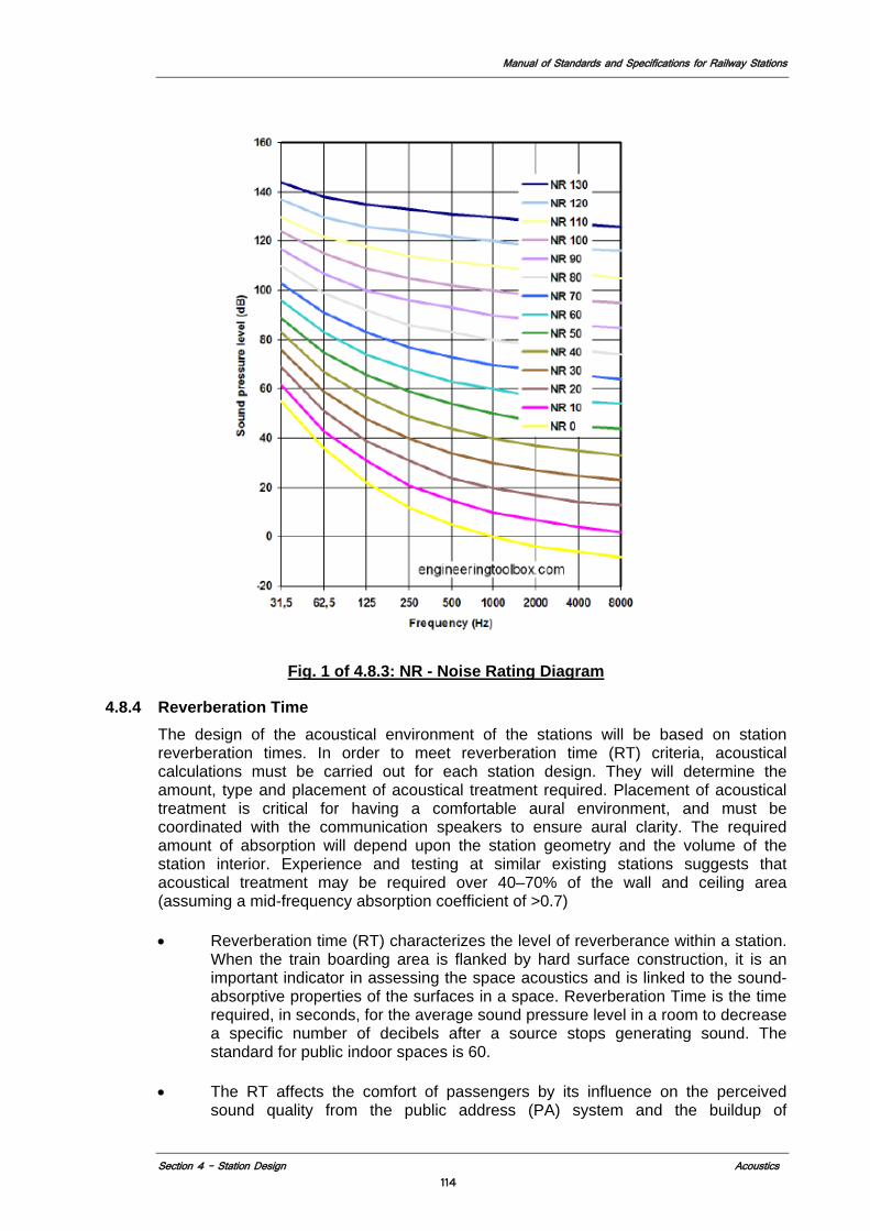
Manual of Standards and Specifications for Railway Stations
Section 4 – Station Design Acoustics 114
Fig. 1 of 4.8.3: NR - Noise Rating Diagram
4.8.4 Reverberation Time
The design of the acoustical environment of the stations will be based on station reverberation times. In order to meet reverberation time (RT) criteria, acoustical calculations must be carried out for each station design. They will determine the amount, type and placement of acoustical treatment required. Placement of acoustical treatment is critical for having a comfortable aural environment, and must be coordinated with the communication speakers to ensure aural clarity. The required amount of absorption will depend upon the station geometry and the volume of the station interior. Experience and testing at similar existing stations suggests that acoustical treatment may be required over 40–70% of the wall and ceiling area (assuming a mid-frequency absorption coefficient of >0.7)
• Reverberation time (RT) characterizes the level of reverberance within a station.
When the train boarding area is flanked by hard surface construction, it is an important indicator in assessing the space acoustics and is linked to the sound-absorptive properties of the surfaces in a space. Reverberation Time is the time required, in seconds, for the average sound pressure level in a room to decrease a specific number of decibels after a source stops generating sound. The standard for public indoor spaces is 60.
• The RT affects the comfort of passengers by its influence on the perceived
sound quality from the public address (PA) system and the buildup of
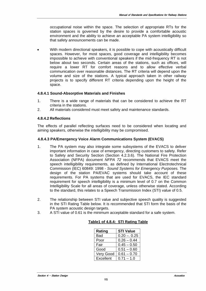
Manual of Standards and Specifications for Railway Stations
Section 4 – Station Design Acoustics 115
occupational noise within the space. The selection of appropriate RTs for the station spaces is governed by the desire to provide a comfortable acoustic environment and the ability to achieve an acceptable PA system intelligibility so that safety announcements can be made.
• With modern directional speakers, it is possible to cope with acoustically difficult
spaces. However, for most spaces, good coverage and intelligibility becomes impossible to achieve with conventional speakers if the mid-frequency RT is not below about two seconds. Certain areas of the stations, such as offices, will require a lower RT for comfort reasons and to allow effective verbal communication over reasonable distances. The RT criteria will depend upon the volume and size of the stations. A typical approach taken in other railway projects is to specify different RT criteria depending upon the height of the space.
4.8.4.1 Sound-Absorptive Materials and Finishes
1. There is a wide range of materials that can be considered to achieve the RT criteria in the stations.
2. All materials considered must meet safety and maintenance standards.
4.8.4.2 Reflections
The effects of parallel reflecting surfaces need to be considered when locating and aiming speakers, otherwise the intelligibility may be compromised.
4.8.4.3 PA/Emergency Voice Alarm Communications System (EVACS)
1. The PA system may also integrate some subsystems of the EVACS to deliver important information in case of emergency, directing customers to safety. Refer to Safety and Security Section (Section 4.2.3.6). The National Fire Protection Association (NFPA) document NFPA 72 recommends that EVACS meet the speech intelligibility requirements, as defined by International Electrotechnical Commission (IEC) 60849: 1998 - Sound Systems for Emergency Purposes. The design of the station PA/EVAC systems should take account of these requirements. For PA systems that are used for EVACS, the IEC standard requirement for speech intelligibility is a minimum level of 0.7 on the Common Intelligibility Scale for all areas of coverage, unless otherwise stated. According to the standard, this relates to a Speech Transmission Index (STI) value of 0.5.
2. The relationship between STI value and subjective speech quality is suggested
in the STI Rating Table below. It is recommended that STI form the basis of the PA system acoustic design targets.
3. A STI value of 0.61 is the minimum acceptable standard for a safe system.
Table1 of 4.8.4: STI Rating Table
Rating STI Value Bad 0.20 –. 0.25Poor 0.26 – 0.44 Fair 0.45 – 0.50 Good 0.51 – 0.60 Very Good 0.61 – 0.70 Excellent 0.71 – 1.0
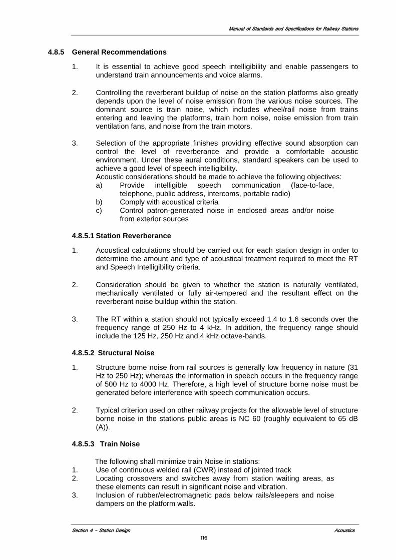
Manual of Standards and Specifications for Railway Stations
Section 4 – Station Design Acoustics 116
4.8.5 General Recommendations
1. It is essential to achieve good speech intelligibility and enable passengers to understand train announcements and voice alarms.
2. Controlling the reverberant buildup of noise on the station platforms also greatly
depends upon the level of noise emission from the various noise sources. The dominant source is train noise, which includes wheel/rail noise from trains entering and leaving the platforms, train horn noise, noise emission from train ventilation fans, and noise from the train motors.
3. Selection of the appropriate finishes providing effective sound absorption can
control the level of reverberance and provide a comfortable acoustic environment. Under these aural conditions, standard speakers can be used to achieve a good level of speech intelligibility. Acoustic considerations should be made to achieve the following objectives: a) Provide intelligible speech communication (face-to-face,
telephone, public address, intercoms, portable radio) b) Comply with acoustical criteria c) Control patron-generated noise in enclosed areas and/or noise
from exterior sources
4.8.5.1 Station Reverberance
1. Acoustical calculations should be carried out for each station design in order to determine the amount and type of acoustical treatment required to meet the RT and Speech Intelligibility criteria.
2. Consideration should be given to whether the station is naturally ventilated,
mechanically ventilated or fully air-tempered and the resultant effect on the reverberant noise buildup within the station.
3. The RT within a station should not typically exceed 1.4 to 1.6 seconds over the
frequency range of 250 Hz to 4 kHz. In addition, the frequency range should include the 125 Hz, 250 Hz and 4 kHz octave-bands.
4.8.5.2 Structural Noise
1. Structure borne noise from rail sources is generally low frequency in nature (31
Hz to 250 Hz); whereas the information in speech occurs in the frequency range of 500 Hz to 4000 Hz. Therefore, a high level of structure borne noise must be generated before interference with speech communication occurs.
2. Typical criterion used on other railway projects for the allowable level of structure
borne noise in the stations public areas is NC 60 (roughly equivalent to 65 dB (A)).
4.8.5.3 Train Noise
The following shall minimize train Noise in stations:
1. Use of continuous welded rail (CWR) instead of jointed track 2. Locating crossovers and switches away from station waiting areas, as
these elements can result in significant noise and vibration. 3. Inclusion of rubber/electromagnetic pads below rails/sleepers and noise
dampers on the platform walls.
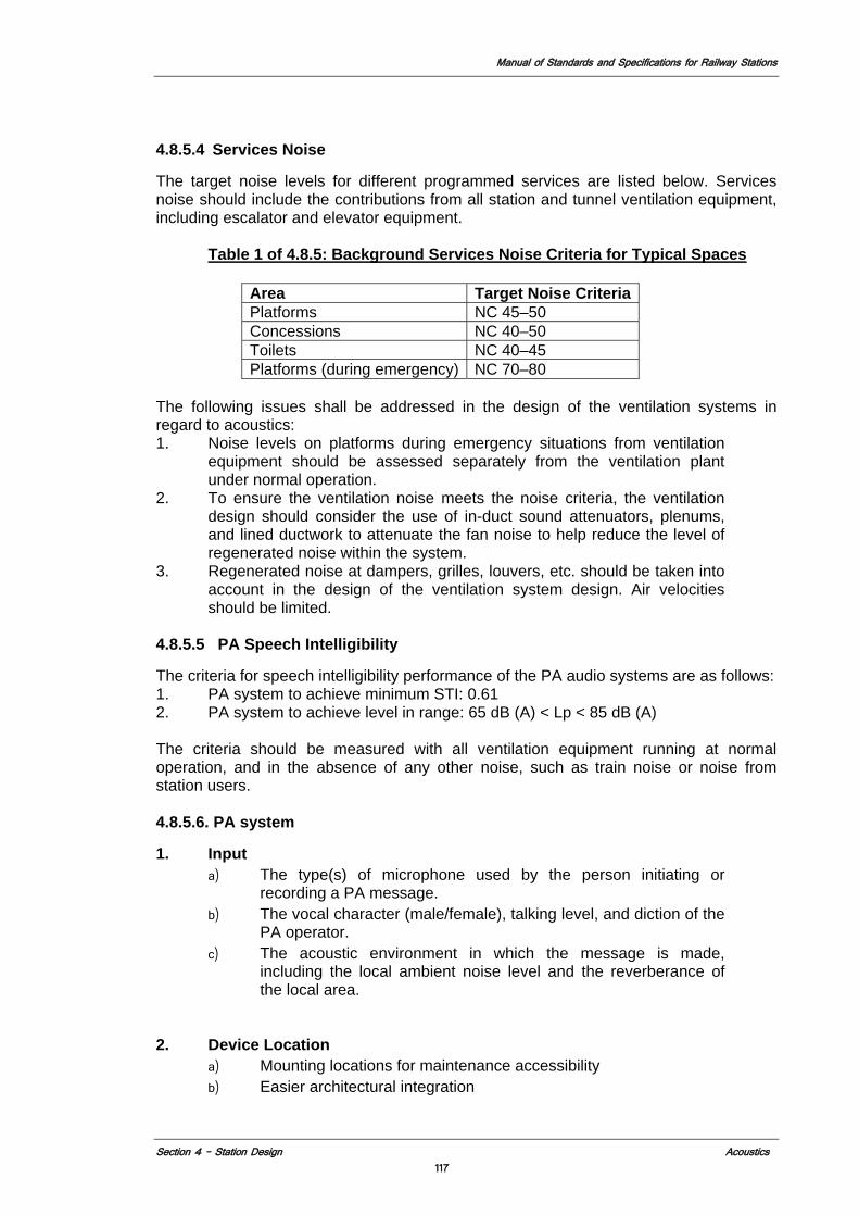
Manual of Standards and Specifications for Railway Stations
Section 4 – Station Design Acoustics 117
4.8.5.4 Services Noise
The target noise levels for different programmed services are listed below. Services noise should include the contributions from all station and tunnel ventilation equipment, including escalator and elevator equipment.
Table 1 of 4.8.5: Background Services Noise Criteria for Typical Spaces
The following issues shall be addressed in the design of the ventilation systems in regard to acoustics: 1. Noise levels on platforms during emergency situations from ventilation
equipment should be assessed separately from the ventilation plant under normal operation.
2. To ensure the ventilation noise meets the noise criteria, the ventilation design should consider the use of in-duct sound attenuators, plenums, and lined ductwork to attenuate the fan noise to help reduce the level of regenerated noise within the system.
3. Regenerated noise at dampers, grilles, louvers, etc. should be taken into account in the design of the ventilation system design. Air velocities should be limited.
4.8.5.5 PA Speech Intelligibility
The criteria for speech intelligibility performance of the PA audio systems are as follows: 1. PA system to achieve minimum STI: 0.61 2. PA system to achieve level in range: 65 dB (A) < Lp < 85 dB (A) The criteria should be measured with all ventilation equipment running at normal operation, and in the absence of any other noise, such as train noise or noise from station users.
4.8.5.6. PA system
1. Input
a) The type(s) of microphone used by the person initiating or recording a PA message.
b) The vocal character (male/female), talking level, and diction of the PA operator.
c) The acoustic environment in which the message is made, including the local ambient noise level and the reverberance of the local area.
2. Device Location
a) Mounting locations for maintenance accessibility b) Easier architectural integration
Area Target Noise Criteria Platforms NC 45–50 Concessions NC 40–50 Toilets NC 40–45 Platforms (during emergency) NC 70–80
Manual of Standards and Specifications for Railway Stations
Section 4 – Station Design Acoustics 118
c) Mounting locations to provide optimal sound coverage to passenger areas.
3. Design
Coordinate locations with light fixtures and other interchangeable modular elements, but
consideration of locations in relation to these elements shall not override intended function of the loudspeakers.
a) Use of any special maintenance equipment other than ladders to gain access to loudspeakers may mean station closure to perform repair.
b) Typical loudspeaker heights for maintenance should be limited to 4.268 m above a finished floor.
c) Standard loudspeaker dispersion patterns also require a minimum mounting height to provide adequate coverage. Greater mounting heights increase the potential for spill and an increase in detrimental reflected sound energy.
d) With respect to the control of reflected sound energy, it is very important that the location and coverage of the PA loudspeakers should take into account the location of any sound-absorptive finishes and vice versa. If early reflections from the PA system are left to reverberate through the station, they effectively become noise, limiting the PA signal to noise ratio and the achievable level of speech intelligibility.
4.8.6 Acoustical Treatment Recommendation
4.8.6.1 Uses of Sound Absorption
1. The reverberant noise buildup resulting from an untreated station may compromise the ability of the PA system to provide good speech intelligibility and may result in an uncomfortable aural environment for the station users.
2. The location of any sound-absorptive finishes and the PA loudspeakers should
be coordinated with the station geometry to ensure that early reflections from the loudspeakers are directed towards the area of sound absorption.
4.8.6.2 Acoustical Treatment/Materials
Acoustical treatment is most effective when applied near the source of the noise. Designers shall take these into consideration in selecting acoustical materials and shall create solutions regarding easy accessibility to the materials for replacement. Options may include: 1. Cementitous spray-applied or trowel-applied acoustic materials (above reach of
pedestrians). 2. Non-corrosive metal panels (with or without perforations) with wrapped acoustical
material. Metal panels may have applied coating or natural brushed finish. 3. Rigid, cellular glass block. 4. Suspended acoustic tile (in nonpublic areas only). 5. Cellular glass blocks (typically concealed behind metal panels). 6. Glass fiber blankets that are wrapped in close-weave glass cloth or other non-
flammable sheeting.
4.8.6.3 Acoustical Materials Requirements
1. All acoustical materials shall comply with the following materials requirements: 2. Easily replaceable; requiring no maintenance
Manual of Standards and Specifications for Railway Stations
Section 4 – Station Design Acoustics 119
3. Low flammability; low smoke emission 4. Good long-term and reliable bond or fixing to surfaces 5. Not stained by water; tolerance of water absorption 6. Rot-proof and odorless; resistant to attack by mold and rodents 7. Long service life; cleanable and vandal-resistant 8. Stability when exposed to high positive and negative pressures 9. Ease of fixing to curved and flat surfaces (horizontal and vertical) 10. Access to services or cabling running behind the acoustic paneling 11. Lightweight 12. Resistant to vibration
4.8.6.4 Station Geometry
Station geometry can be designed to ensure sound energy, such as train noise or early reflections from the PA system, is reflected onto sound-absorptive areas, thereby maximizing the benefit of any sound-absorptive treatment. The station design should consider the location of all noise sources and the propagation of early-reflected energy.
Stations with curved or barrel-vaulted ceilings or walls may result in strong focusing of acoustic energy if left untreated. This will greatly reduce the ability of the PA system to provide well, even coverage throughout the station. Removing unwanted focusing effects while retaining the curved geometry could be achieved using sound absorption and/or diffusion.
The curved surface can be made sound absorptive, thereby reducing the strength of any focusing effect. Additionally, increasing the irregularity of the curved surfaces, through the use of coffering or other detailing, can reduce sound focusing. One option for mined stations is to leave the rock face wall exposed; the irregularity in the surface will often be diffusive. This diffusion scatters the sound rather than focusing it.
4.8.6.5 Integration of Noise Attenuation with Structure
Consider integrating acoustic design parameters with the basic design parameters. This could affect the selection of materials and the volumetric definition of the stations. 1. Reduce Noise 2. Efficient Material Use
Manual of Standards and Specifications for Railway Stations
Section 4 – Station Design Signage and Graphics
120
4.9 SIGNAGE AND GRAPHIC
4.9.1 Introduction Signage is the most visible, most scrutinized station element and essential to the proper functioning of the station. Signage provides information essential to passenger use and navigation of the system, engendering a sense of reassurance, security, and orientation when entering, exiting, or transferring, which contributes to a positive, user-friendly customer experience. In brief, signage:
• Guides passengers to and from the various station areas • Accommodates the myriad informational requirements of the station and its
service • Informs passengers of service information • Accelerate their way finding process • To relieve them of their information anxieties
Codes and Standards The latest editions of the following reference standards, regulations and codes will be utilized: Photograms for premise” by IRICEN Pune 1995 Policy circular No.2 – commercial Directorate, dated 11/3/99, Sub: Standardisation of signage of station
International Transportation graphic Standards ”Guidelines for Transit facility; Signing and Graphic”, TCRP Report 12, Transportation research Board; National Academy press, Washington, D.C 1996. Signage for Rail Users MOR RDSO/SPN/TC/61/2007 RDSO/SPN/TC/67/2006
4.9.2 Goals and Objectives In new stations signage shall not substitute for clear unobstructed circulation and line of site. Wayfinding must begin with the station circulation and access design, and signage should play primarily an informational role. 1. Integrate signage with station architecture and other station elements. 2. Utilize electronic messaging systems (new technologies) in conjunction with
fixed signage units when appropriate. 3. Reduce customer anxiety levels and dependency on Indian Railway employees
for directions and information. 4. Encourage tourists, new and infrequent users and individuals with disabilities to
utilize the system with ease. 5. Coordination with MOR existing signage guides 6. General principles for signage placement in new stations shall include:
a) Keeping signs to the minimum necessary to properly communicate the required information, while considering that certain signs need to be repeated to reassure passengers that they are on the correct path.
b) Placing signs exactly at decision points in lateral and vertical circulation paths, including VCEs.
c) Placing signs perpendicular to the line of travel or sight.
Manual of Standards and Specifications for Railway Stations
Section 4 – Station Design Signage and Graphics
121
d) Glow sings for publicity should be placed parallel to the passenger movement in the station. Placement of commercial signs should not obstruct any station sign.
e) To reduce sign clutter, utilizing both sides of signs for information display wherever applicable.
f) Integrating signage with other station elements wherever possible. g) To enhance signage recognition and reduce visual clutter, establishing
vertical datum lines or placement zones for signage. These datum lines should be within the normal cone of vision of persons standing in the station and sitting on the train. Datum lines for tactile/Braille ADA plaques will differ than those for overhead signs.
h) Placing signs in areas that have clear sight lines and are free of visual obstructions.
i) As per ADA, the international symbol of accessibility (ISA) is required to identify accessible entries and paths. (See section 4.3.3) All components of signage at station must have a Braille component.
j) To encourage left-hand circulation, placing signage or sign information on the left hand sides of corridors and VCEs.
k) Graphics in floor should clearly indicate the movement lines, space allocated for vendors, location of pantry car of train on the platform for easy flow of raw material and other material required for train operations.
l) All signage shall have alternate pictorial signage of the same size as the letters and should be in at least Tri- Lingual (English, Hindi & local Language). .
4.9.3 Sign Information Content System
The sign information content system is defined as the informational messages contained on signage. Essential public information and signage can be of retro reflective high intensity prismatic boards. Aspects of new/renovated stations that may create new informational needs for fixed signage include: 1. Identification and way finding 2. Identification of dedicated emergency exit stairs and areas of refuge 3. Reinforcement of left-hand circulation at vertical circulation elements (VCEs) and
passageways 4. Identification of help-point intercoms (HPIs) 5. Indication of escalator status and direction for all passengers, including those
with impairments.
4.9.4 Sign Graphic System
The sign graphic system is defined as the graphic elements, such as typography, arrows, symbols, and colors, which organize and convey the sign informational content. Detailed technical standards regarding these elements and their size and arrangement on fixed signage modules shall be provided by the Ministry of Railways. (Refer “Photograms for premise by IRICEN Pune 1995 (See Annexure II -Signage manual).These standards create a consistent graphic look for the Indian Railway system and contribute to a cohesive visual identity.
For the information for passengers, the size of the letters in the sign boards depicting major information like platform number, direction, entry, exit shall not be less than 300 mm, for information of facilities it should not be less than 230mm and for other information not less than 78mm.

Manual of Standards and Specifications for Railway Stations
Section 4 – Station Design Signage and Graphics
122
For signage whose graphic configuration is not covered in the MOR IRICEN Pune 1995 or Policy circular No.2 – commercial Directorate, dated 11/3/99; Sub: Standardisation of signage of stations, the international transportation graphic standard signs shall be used (see Annexure III international transportation graphic standard signs). 4.9.4.1 Color code Colors for information of emergencies, train arrivals, departures, location of passenger amenities and any other information to the passengers shall use existing MOR specifications (Refer Policy circular No.2 – commercial Directorate, dated 11/3/99; Sub: Standardisation of signage of stations). Only permissible colors shall be followed but with attractive shades and using latest computer printing technology in form of retro reflective stickers or on flex.
Table 1of 4.9.4: - Table Illustrating colour code for signage at railway station
Type of signage Colour of Background Colour of Signage matter
Signage for services YELLOW BLACKSignage for utilities BLUE WHITESignage for caution RED WHITESignage for direction YELLOW BLACK
In the station circulating area GREEN WHITEIn the municipal area on the station approach roads. BLUE WHITE
Glowsigns within the station Building
Reflective directional signages outside the station Building
Source: - Policy circular No.2 – commercial Directorate, dated 11/3/99, Sub: Standardization of signage of stations
The pictorial signs will use the existing guideline of MOR. (Refer Signage for Rail Users; MOR). Where signage color and form are not specified in MOR standards the designer shall follow international transportation standards (see Annexure III international transportation graphic standard signs).
4.9.4.2 Size of Signage Size of signage shall be standardized for all similar types of signs throughout the station as called for in the referenced standards. For any signage not covered, the Concessionaire shall prepare a schedule for submission to MOR identifying each type of sign, its proposed size and configuration and location(s) along with the same information on the signs defined by the referenced standards. 4.9.4.3 Sign Hardware System
The sign hardware system is defined as the physical sign units—their sizes, materials, and attachment methods—that display the sign graphics. The technical fabrication details for the fixed signage hardware system shall be in accordance with security requirements and shall be approved by the MOR. (Refer Policy circular No.2 – commercial Directorate, dated 11/3/99; Sub: Standardisation of signage of stations). The construction of the signs themselves if not specified in the referenced standards shall be on a non combustible durable design mounted on metal frames and supports as required from the ceiling walls and floors of the stations.
Opportunities to integrate signage with other station elements should therefore be evaluated in the process of designing new stations. For example, a modular approach is
Manual of Standards and Specifications for Railway Stations
Section 4 – Station Design Signage and Graphics
123
encouraged in the architectural design of new stations, which provides opportunities for signage integration (e.g., the series of reveals that are likely to occur in)
4.9.3.4 Crossover/Redundancy of Fixed and Variable Signage
To ensure that passengers receive the information they need to use the train system, a certain amount of informational redundancy should be maintained between fixed and variable signage at new stations. While permanent service information signage is provided by fixed signage at platform edges, temporary service diversion information may be conveyed by electronic and temporary signage. Electronic signage cannot be solely relied upon to convey such information for several reasons. 1. Certain languages may not be available or readily legible on electronic displays. 2. The computer systems controlling the electronic signage may fail 4.9.3.5 Integration of Fixed and Variable Signage
The design of new stations presents new opportunities for integration of fixed and variable signage elements in a unified manner. For example, LED or other electronic display elements could be detailed into the fixed signage hardware system to provide both permanent and variable information.
4.9.5 Types of Signs and Graphics The types of signage described below are classified according to the information conveyed.
4.9.5.1 Fixed or Static Signage Fixed or static signage contains information generally considered as permanent or unchanging in nature, such as station name, direction and destination of service (e.g., “Mumbai & Pune”), or the way out (“Exit”). While fixed signage is considered permanent, even the information it contains is subject to change to reflect changes in station or train operations over time. Following would be fixed signs:
1. Directional (exterior, unpaid area and concourse)
a. Station entrance at drop off areas b. Ticketing window c. Information d. Concourse gates e. Amenities (water, toilets, food, luggage, waiting areas, lounges etc) f. Platforms and tracks g. Elevators h. Egress
2. Directional (Platforms and tracks) a. Concourse b. Other platforms c. Egress d. Elevators e. Multimodal connections
3. Identification a. Station Entrance(s) b. Ticket windows c. Information d. Concourse gates
Manual of Standards and Specifications for Railway Stations
Section 4 – Station Design Signage and Graphics
124
e. Amenities (water, toilets, food, luggage, waiting areas, lounges etc) f. Platforms and tracks g. Elevators h. Egress i. Station name (platform) j. Coach location (platform) k. Track number (platform) l. Room numbers and names in none public areas
4.9.5.2 Variable or Dynamic Signage
Variable or dynamic signage information content changes more often than fixed signage. All electronic Signage shall have power and data connections and be part of the integrated train information system. Variable signage for stations takes the following forms: 1. Exterior, unpaid area and departure concourse
a) Main train information displays (see section 4.9.5.4) b) Reserved seat boards c) Reserved seat availability status boards d) Train information for arriving/departing trains by track (Ref annexure IX: -
RDSO specification no RDSO/SPN/TC/61/2007) 2. Platform and tracks
a) Train information for arriving trains by track a) Coach type
3. TVMs should also display this information. 4.9.5.3 Main Train Information Display This is a large electronic multi color display sign set above eye level for 120o view at a distance of 100m. The sign will have the following information: 1. Train ID 2. Train Route 3. Arrival or departure information 4. Track number 5. Status 6. Digital time display synchronized with all other station clocks Display will be integrated to the MOR train information system. (Ref annexure III: -RDSO specification no RDSO/SPN/TC/67/2008) 4.9.5.4 Station Information Centre (SIC)
SIC will be a large stand alone static, well-lit fixed sign that will contain on both sides the following: 1. A route map noting location of station. 2. A vicinity map noting location of station. 3. A station map noting location of SIC. 4. Notation of all intermodal connections. This sign should be equipped with power and data connections to facilitate future additions of dynamic information displays. 4.9.5.5 Identification Signage
Identification signage is defined as signs that identify a place, space, entity, or object. In the wayfinding process, identification signs confirm that a destination has been reached. Identification signs can also create a visual or brand identity.
Manual of Standards and Specifications for Railway Stations
Section 4 – Station Design Signage and Graphics
125
4.9.5.6 Way finding/Directional Signage Way finding signage, or directional signage, is defined as signs that display text, typically paired with directional arrows, to guide people in finding their way into, within, and out of a station. Wayfinding signs are essential for effective orientation and navigation, reducing passenger confusion and improving circulation. Directional signage enhances a passenger’s sense of security and well being, contributing to a positive passenger experience. 4.9.5.7 Information Signage
Information signage is defined as signs that neither identifies nor direct, but display information about the use or operation of a place or system. 4.9.5.8 Station Entrance Open/Closed, Hours
These signs display the hours of operation, and whether the Station is Open or closed. 4.9.5.9 Intermodal Connections
Display of intermodal connection information on both fixed signages and variable and dynamic signages must be placed at platform gates. 4.9.5.10 HPIs
HPIs will be located throughout the stations, and should be clearly identified with fixed signage. Also see 4.11.6.2 4.9.5.11 Emergency Exits
Dedicated emergency egress stairs, typically at both ends of the station, will require applicable door and stair side signage per applicable codes. These stairs should not be signed as normal, non-emergency station exits. These would be of fixed types. 4.9.5.12 Prohibitory Signage
Prohibitory signage is defined as signs that prohibit or warn against certain behavior. These typically include rules of conduct and platform end signs. 4.9.5.13 Tactile/Braille ADA Signage
Tactile/Braille ADA signage is defined as signs that are required by for the visually impaired under the American Disabilities Act and/or Indian Disability Act. These signs, displaying tactile lettering and grade 2 Braille, are required in addition to signage, described above for the non-visually impaired. Tactile/Braille ADA sign plaques are required to be mounted with the sign’s centerline 1524 mm above the ground or floor. Tactile hazard markings shall be provided at danger areas such as escalator landings, stairwells, and passenger lift accesses. Any obstructions such as freestanding signs, telephone enclosures, or fire hose cabinets shall be cane detectable and protected, either by horizontal bars set 100mm above floor level, or by a wing wall around the obstructions. (See section – 4.3.2.2 and 4.3.4.1). To help the visually impaired persons to use the stairs or escalators, there are tactile guide paths with audible warnings at top and bottom. These signs should cover, along the whole path of travel and all component of signage at station must have a Braille component.
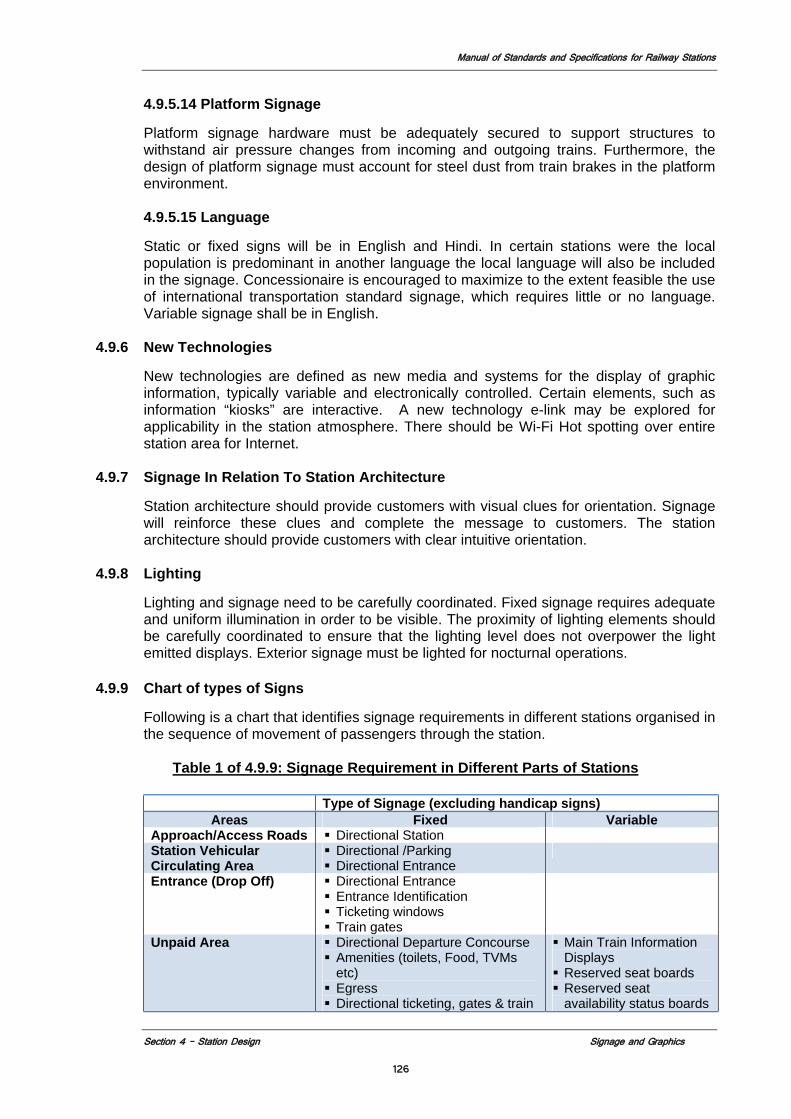
Manual of Standards and Specifications for Railway Stations
Section 4 – Station Design Signage and Graphics
126
4.9.5.14 Platform Signage
Platform signage hardware must be adequately secured to support structures to withstand air pressure changes from incoming and outgoing trains. Furthermore, the design of platform signage must account for steel dust from train brakes in the platform environment.
4.9.5.15 Language
Static or fixed signs will be in English and Hindi. In certain stations were the local population is predominant in another language the local language will also be included in the signage. Concessionaire is encouraged to maximize to the extent feasible the use of international transportation standard signage, which requires little or no language. Variable signage shall be in English.
4.9.6 New Technologies
New technologies are defined as new media and systems for the display of graphic information, typically variable and electronically controlled. Certain elements, such as information “kiosks” are interactive. A new technology e-link may be explored for applicability in the station atmosphere. There should be Wi-Fi Hot spotting over entire station area for Internet.
4.9.7 Signage In Relation To Station Architecture
Station architecture should provide customers with visual clues for orientation. Signage will reinforce these clues and complete the message to customers. The station architecture should provide customers with clear intuitive orientation.
4.9.8 Lighting
Lighting and signage need to be carefully coordinated. Fixed signage requires adequate and uniform illumination in order to be visible. The proximity of lighting elements should be carefully coordinated to ensure that the lighting level does not overpower the light emitted displays. Exterior signage must be lighted for nocturnal operations.
4.9.9 Chart of types of Signs
Following is a chart that identifies signage requirements in different stations organised in the sequence of movement of passengers through the station.
Table 1 of 4.9.9: Signage Requirement in Different Parts of Stations
Type of Signage (excluding handicap signs)
Areas Fixed Variable Approach/Access Roads Directional Station Station Vehicular Circulating Area
Directional /Parking Directional Entrance
Entrance (Drop Off) Directional Entrance Entrance Identification Ticketing windows Train gates
Unpaid Area Directional Departure Concourse Amenities (toilets, Food, TVMs etc)
Egress Directional ticketing, gates & train
Main Train Information Displays
Reserved seat boards Reserved seat availability status boards
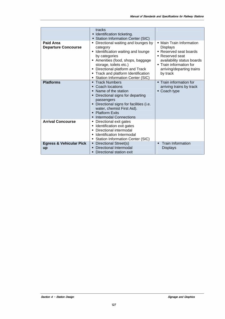
Manual of Standards and Specifications for Railway Stations
Section 4 – Station Design Signage and Graphics
127
tracks Identification ticketing. Station Information Center (SIC)
Paid Area Departure Concourse
Directional waiting and lounges by category
Identification waiting and lounge by categories
Amenities (food, shops, baggage storage, toilets etc.)
Directional platform and Track Track and platform Identification Station Information Center (SIC)
Main Train Information Displays
Reserved seat boards Reserved seat availability status boards
Train information for arriving/departing trains by track
Platforms Track Numbers
Coach locations Name of the station Directional signs for departing
passengers Directional signs for facilities (i.e.
water, chemist First Aid). Platform Exits Intermodal Connections
Train information for arriving trains by track
Coach type
Arrival Concourse Directional exit gates Identification exit gates Directional intermodal Identification Intermodal Station Information Center (SIC)
Egress & Vehicular Pick up
Directional Street(s) Directional Intermodal Directional station exit
Train Information Displays
Manual of Standards and Specifications for Railway Stations
Section 4 – Station Design Art and Advertisements
128
4.10 ART AND ADVERTISING
4.10.1 Art Work 4.10.1.1 Introduction The inclusion of public art within the station complex can be a trigger for recognition, orientation and wayfinding. The designer of the station shall work in a collaborative process for creating new station design theme with architecture and artwork that is integral to the station environment and its uniqueness. MOR shall encourage artists and architects/designers to collaborate during the early stages of rehabilitation/ redevelopment process in order to present an overall artistic/aesthetic vision for stations. Related sections in this manual: 1. Design and Planning Principles 2. Operations and Maintenance 3. Materials and Finishes 4. Lighting 5. Signage and Graphics 4.10.1.2. Art at Stations Art has to be included as an integral component of the Indian Railway Stations, similar to a few stations that are of heritage significance, such as Chatrapati Shivaji Station, Mumbai and Chennai Central etc. Art work improves the culture and environment of the station, hence it should be encouraged. Utmost care must be taken towards the upkeep of the Heritage stations or site within the station campus. The management of the station should run programs to educate the passenger on the importance/ history of the heritage site and building to create sense of identification of the station as part of or an extension of the site. 4.10.1.3. Approach to Permanent Art for Railway Stations
Railway station Concessionaires shall explore new possibilities for a Permanent Artwork Program. These opportunities could allow the concessionaire to consider work by contemporary artists with a broad vision or scope for sophisticated and fully integrated public artwork. The design and construction of stations will allow for a more contemporary artwork program within newly designed and constructed stations. However, incorporation of new artwork within the fabric of an already designed and often “decorated” and “older” (sometimes even historic) environment will be taken into consideration of the aesthetic of the existing station. Any artwork or ad panel shall not in any way interfere with passenger circulation, station function, passengers view to various information, important instructions/signage, and emergency sign boards. 4.10.1.4. Architect and Artist Collaboration
The artist shall work closely with the architect as part of the overall design team. The architect / designer should immediately begin to interface with the Artist as a unified group to select ideas and artists compatible with their own initial vision for the station
Manual of Standards and Specifications for Railway Stations
Section 4 – Station Design Art and Advertisements
129
itself. The Artist will be responsible for working with the architects and Indian Railway staff to ensure that all phases of the artwork components and their final integration are coordinated with the appropriate parties.
4.10.1.5. Practical Requirements
1. Selection and Durability of Artwork Materials
The goal for this collaborative team will be to develop ideas that use materials or technology in innovative ways. Durable materials successfully used in previous permanent artwork projects and which are common, acceptable and historically able to be maintained easily in the Indian railways will be considered first and foremost—this may include but is not limited to the following: a) Glass and ceramic mosaics b) Ceramic tile c) Terracotta d) Granite and other stone e) Hand-made glass elements, bronze and other materials f) Lighting g) Metals h) Video environments i) Sound environments
2. Artwork Maintenance
Art work will be maintained in accordance with the artist’s recommendation. Art work as per specified material in the manual shall be used. Concessionaire shall be responsible for its upkeep, regular maintenance, cleaning polishing, theft of part or whole or any activity required to keep it in presentable condition.
3. Lighting
Art work will be illuminated in accordance with the artist’s recommendation.
4. Review
Art at a station should be integral to the overall station design. MOR review of art will be part of the overall station design review through the IE. However any station with heritage status will require a separate review of the art and preservation plan to endure conformance with regulations affection national heritage structures.
4.10.2 Advertising 4.10.2.1. Introduction
Advertising shall be seamlessly woven into the station fabric. It will be Integrated into station design, create a safe environment with clear advertising that does not confuse or conflict with directional signage and information signage. The outer elevation walls of the station will not be used for advertisement. No hoardings and signboards shall be permitted within the station boundary. 4.10.2.2. General Criteria
Advertising space shall be planned and integrated into the station design, and should be used to enliven and enrich the overall ambience of the station design solutions. The
Manual of Standards and Specifications for Railway Stations
Section 4 – Station Design Art and Advertisements
130
location, quantity, and type of advertising panels required in a station will vary depending on the station configuration, and maintenance requirements.
1. Advertising plan of the station: - Advertising plan should be prepared for the
station by identifying the proposed locations (like main circulating area, platforms etc.) And total surface area earmarked for advertising to be managed by the concessionaire, as approved by MOR and would be a schedule to the concessionaire agreement. Advertising plan for the station shall be developed in close collaboration with the station designer and the plan submitted to MOR shall have the written concurrence of the station designer.
2. Approval of text: - Concessionaire, should obtain prior approval from railway
administration for all advertisement to be displayed. Advertisement pertaining to hazardous products, obscenity, competition to railway transport and any other subject/item considered objectionable under Acts and laws of the government (local and union) shall not be displayed.
3. Advertising panels should conform to the Advertising plan of the station and be
displayed on prescribed percentage and location total surface area of the walls of building (internal walls of station/platform facing platforms circulation areas) after deducting doors, windows ventilators and information boards& officer’s or official’s name plate.
4. On all platforms unless infeasible architecturally a unified design which includes
the size, configuration and mounting details shall be developed – the frame, graphic and mounting materials shall be incombustible with low fuel contribution ratios. Typical construction should be like mild steel angle iron, pipes, or channels for support and mounting. Advertisement media could be on computer flex printed or printed with proper lamination with 50 micron sheet or printed on paper framed in acrylic, plastic glass box of at least 5mm in thickness of same size, shape design (outer frame and box material) also to metal and have uniformity in style.
5. The designer shall explore advertising on different surfaces, vertical and
horizontal, as well as placement of particular objects. Advertising types and technologies shall be evaluated, assessed and recommended to MOR for approval.
6. Placement and spacing of advertising shall be integrated into the station design,
creating designated areas for the advertisement that do not conflict with customer flow and safety and clarity of signage in the station.
7. Advertising shall be located so that it is accessible for maintenance and
replacement, without hindering the operation of the station.
8. Advertising locations shall not interfere with orderly passenger circulation. Moving images shall not be used in areas where passengers are in motion unless there is adequate space.
9. At no given time, advertising shall be located in areas where it may conflict with
signage.
Manual of Standards and Specifications for Railway Stations
Section 4 – Station Design Art and Advertisements
131
10. Locations for information signage, directional signage and art shall be coordinated with advertising, and advertising shall not compete with information signage requirements.
11. Advertising panels shall not be placed on gates, barriers or interior railings.
12. The placement and location of advertising should discourage defacement or
damage.
13. Application of advertising panels shall not be part of the permanent finish of the station.
14. Information kiosks will be located in selected station areas and will be utilized to
provide passengers with transportation and local neighborhood information. They also may be used to provide advertising information, including current news, stock, weather, local events, local businesses, and ability to check email.
15. There shall be no advertising through or on the customer information signs.
16. The advertisement panels shall be maintained by the concessionaire through the
company owner to which the ad belongs. In case the ad panel is not observed to be in presentable condition and creating an undesirable look, it will be immediately removed by the station authority or replaced by new one on the cost of concessionaire.
4.10.2.3 Types Of Advertisement
1. Poster Print Advertising
2. Illuminated Poster Advertising
3. Projection Advertising: If used, shall be configured to result in a minimum 1.25m
by 2m image with no discernable distortion form the projection. Projection must be timed and coordinated with the train schedule for maximum visibility to passing passengers. The station designer shall coordinate and integrate the projection surface material into the station design.
4. Advertising/Information Screens: Technology provides changing written
stationary advertising via a flat screen, which requires a 50 mm to 100 mm depth with data line infrastructure connection. State of the art advertising medium shall meet the same criteria as signage in order to assure advertising legibility/visibility. The bottom of the projection must be a minimum of 2.591 m above the finish floor. Size, quantity, and location of advertisement shall be considered on a station-by-station basis.
5. Wrap Graphics: Wrap graphics may “wrap” walls, guardrails, and columns. Wrap
graphics shall not be used on floors, as safety and slip-resistance may be compromised.
6. Flip Page Advertising: Flip page advertising uses a low-tech advertising backlit
box with a mechanical system (typically rollers) of changing between several different advertisements.
Manual of Standards and Specifications for Railway Stations
Section 4 – Station Design Art and Advertisements
132
4.10.2.4 Design Criteria A combination of the above means of advertising may be adopted at stations. Whatever media is used it must be integrated into the station design and not be treated as add on element at a later date. All wiring and fixings must be concealed. Provision shall be made for cast in conduit and fixings for advertising media at identified sites whether or not the media is installed at the opening of the railway. Attention shall be paid to ensuring maintenance access to these zones. Size of advertising panels shall be consistent throughout the station in all similar sized and proportioned parts of the station to maintain visual consistency. A minimal number of sizes and configurations shall be established for each part of the station to minimize visual clutter. Following are station components where the same advertising configurations should be planned. 1. All platforms, all corridors (where advertising is permitted), all areas where
ceiling is less the 3m high 2. Unpaid areas, arrival concourse (high ceiling areas) 3. Main departure concourse (highest ceiling area).
Manual of Standards and Specifications for Railway Stations
Section 4 – Station Design Fixed Furniture and Equipment
133
4.11 FURNITURE, FIXTURES AND EQUIPMENT (FF&E) 4.11.1 Introduction
It is imperative that the furniture and fixtures that facilitate passenger comfort, convenience and safety, also be durable and designed for minimal maintenance and repair. The design of these objects, therefore, shall in corporate innovative technology and material, keeping in alliance with the sustainable design policy of the Indian Railways, and as described in the Sustainable Development and Environmental Consideration section (see section 5.2).
4.11.2 Goals and Objectives Station FF&E shall be integrated into the overall station architecture and utilize system wide standard designs to the extent possible. FF&E shall be designed as groups of related amenities and arranged to complement and enhance the functionality of the individual elements.
References Applicable codes and standards include, but are not limited to, the latest editions of the following reference standards, regulations, National (USA and India) Design Guidelines/Policy Instructions and codes: National Building code of India Bureau of Indian Standards Indian Railway Works Manual, 2000 Telecom Directorate specification no RDSO/SPN/TC/62/2007 for digital clock with GPS Synchronization.(See Annexure V) Telecom Directorate specification no RDSO/SPN/TC/76/2008 for Analog clock with GPS Synchronization (See Annexure VI) Telecom Directorate specification no RDSO/SPN/TC/65/2006 for Surveillance system. (See Annexure VII) Telecom Directorate specification no RDSO/SPN/TC/63/2006 for Public Address system. (See Annexure VIII) Telecom Directorate specification no RDSO/SPN/TC/61/2007 for Integrated Passenger Information system. (See Annexure IX)
4.11.3 Furniture Seating 4.11.3.1 Seating Criteria in the Main Waiting Areas
1. General
a) Seating shall be grouped in the designated waiting areas b) Seating requirement (no of seats) in the main waiting area shall be in
accordance with the passenger volume of the station. c) Seating shall be arranged with end tables d) Seating should be placed outside the paths of circulation, and should not
block queuing or otherwise obstruct passenger movement 2. Seating should be located near accessible elevators and entrances to assist
elderly and mobility impaired passengers 3. Unreserved
a) Seating shall be located nearest the entry area of the station in straight rows to achieve the maximum density.
b) Seating shall be of standard modular design with the following attributes • Flexible molded incombustible individual seats fixed to support
frame • Scratch and stain resistant
Manual of Standards and Specifications for Railway Stations
Section 4 – Station Design Fixed Furniture and Equipment
134
• Support frame to be non corroding metal fixed to the floor • Easily maintainable (cleaning by traditional cleaning methods,
hardware for easy removal and replacement) • Color to be consistent in all seats all unreserved waiting areas
4. Reserved a) Seating should be located toward the area of concessions and amenities
and be clearly distinct from the other seating areas. Configuration should include seating in sections perpendicular to each other.
b) Seating shall be of standard modular design with the same attributes of the unreserved seating; however color should be different than for unreserved seating.
5. Platform a) Seating should be located parallel to track clear of coach door openings b) There shall be a minimum seating capacity of 100 at each platform c) Seating shall be of standard modular design with the following attributes
• Flexible molded incombustible grouped seats fixed to support frame
• Scratch and stain resistant • Support frame to be non corroding metal fixed to the floor • Easily maintainable (cleaning by traditional cleaning methods,
hardware for easy removal and replacement) • Color to be consistent in all seats and all platforms
6. Lounges a) Seating shall be located within designated lounges in lounge type
configuration b) Seating shall be of standard modular design with the following attributes
• Comfortable upholstered incombustible seats in stand alone single and multiple units
• Scratch and stain resistant • Furniture frame should be non corroding metal fixed to the floor • Easily maintainable (cleaning by traditional cleaning methods) • Color(s) to be consistent in all seats all similar lounge areas
4.11.3.2 Method of Attachment of furniture
All seating units and related objects shall be permanently and securely fastened to the station architecture via the floor, wall, or column. Any exposed fasteners must be tamper-resistant. The method of fastening should consider normal maintenance needs, and be vandal and tamper-resistant and materials shall be none corroding. Method of attachment should take maintenance needs into consideration; seating should be either floor-mounted in such a way that permits floor scrubbing, or made seamless with floor. In addition removal and replacement of furniture that is fixed to floor should be easily accomplished.
4.11.3.3 Lounges In addition to seating the lounges shall also contain the following: 1. Tables, 2. Shelves 3. Book/magazine racks 4. Food/drink vending machines, etc. All items to be incombustible of durable and easily maintainable fabrication designed to create a place of comfort.
Manual of Standards and Specifications for Railway Stations
Section 4 – Station Design Fixed Furniture and Equipment
135
4.11.3.4 Standardization and Variation
Standard furniture types shall be used to simplify maintenance. Standardization may entail dictating a specific piece of furniture, providing a group of selected seating options from which to choose, or indicating a specific seating type. Within a standard system of elements, variety can be achieved by the creative application of standard parts (e.g., a modular system). Variety of form or type will allow for variation in seating providing the station designer with opportunities to integrate seating into the overall architecture. 4.11.3.5 Acceptable Materials
Materials for station seating and related furniture need to be durable, easily maintained, and impervious to rot, rust and corrosion. Materials should also be resistant to fire, infestation, defacement, and normal abuse. Acceptable materials may include metals, stainless steel, mild steel, wrought iron, high strength robust P.V.C. in first class fresh plastics. Concrete and stone may be used for exterior seating if properly sealed. 4.11.3.6 Modularity
Seating shall be a modular system, so that it can be added to or subtracted from, in order to form a single or continuous unit with interchangeable parts. 4.11.3.7 Accessibility
Seating design should accommodate the visually impaired in their use of canes. Provide space for wheelchairs in seating areas.
4.11.4 Recycling and Trash, Receptacles 4.11.4.1 Design
Recycling receptacles must be provided to enhance sustainability in the station design. Receptacles shall be designed so that the top surface is not flat, in order to discourage customers from leaving trash on top, rather than within the container. One Trash receptacle required for 200 sq.m. of area with volume of at least 0.5 cu.m.
4.11.4.2 Location
Trash receptacles shall be strategically placed along expected customer circulation routes, allowing for more effective usage. Trash receptacles should be placed near seating and concessions, for purposes of customer convenience. 4.11.4.3 Method of Attachment
Trash receptacles should be securely fastened to the station structure at the floor, wall or columns. Receptacles should either be mounted off-floor to provide cleaning access underneath units, or made seamless with the floor in order to facilitate maintenance.
4.11.5 Fixtures
4.11.5.1 GPS Clocks
Station Areas with Electronic display systems (Train information, Reservation status display boards etc.) will have an integrated Digital Clock with GPS synchronization as per the Telecom Directorate specification no RDSO/SPN/TC/62/2007. Remaining areas will have Analog clocks with GPS Synchronization (as per Telecom Directorate specification no RDSO/SPN/TC/76/2008) where they are deemed appropriate as per the station design.
Manual of Standards and Specifications for Railway Stations
Section 4 – Station Design Fixed Furniture and Equipment
136
4.11.5.2 Station Information Centre (SIC)
The Station Information Centre provides passengers with railway and vicinity maps, station map, and other customer information.
Design and location of SIC’s shall be as follows:
a) Width of sign shall be a minimum of 3.5 m wide. b) Sign shall start at 0.5 m from the floor and shall be at least 1.5 m high to
the top of the map area. c) The SIC shall have a continuous .25 m high strip providing identification
information. d) It can be wall mounted or free standing in which case both sides will have
the same information. e) A continuous fixture at the top shall down light entire sign. f) Construction shall be of incombustible material with a finished metal
frame and map boards shall be of enameled metal or similar type finish on which to mount map information.
g) SIC to have data and power infrastructure built into and concealed into the frame and available to each of the three portions of the sign.
h) SIC’s shall be located within the station building at: • In the unpaid part of the station near every entry area to the paid
part of the station • In the departure and arrival concourses located in the vicinity of
the platform access points no more than 300 m apart. • At each of the main exit points of the station including access to
multimodal connections. 4.11.5.3 Drinking Fountains/Water outlets
Drinking fountains shall comply with Indian Disability Act 1995 / ADA requirements. See section 5.2.6.2). Drinking water should be filtered by RO process. Drinking water fountains should be preferably in high class chromium plated stainless steel with water cooler housed in mild steel chamber or concrete chamber. Drinking fountains shall be located in such a way that a passenger shall not need to travel more than 300m to reach one. In addition each type of waiting area or lunge shall have at least one water fountain. On platforms there shall be a minimum of 2 water outlets located remotely firm each other to provide potable water for through passengers.
4.11.6 Equipment 4.11.6.1 Public Telephones
1. Location: Telephones provide a means of communication, a sense of security to passengers, and connection to the outside world. They should be located on both the unpaid and paid areas to allow easy access by all passengers. Telephone booth shall be in Fiberglas, MS sheet, Aluminum with M.S. frame, with less use of timber products and laminates. Provide at least one tele-typewriter (text telephone)/telecommunication display device (TTY/TDD) on each level of the station. 2. Positioning: Telephones may be wall-mounted, freestanding, or integrated into passenger information displays or kiosks, among other options. Telephones must be positioned to meet ADA requirements for clear floor space, mounting height and protruding.
Manual of Standards and Specifications for Railway Stations
Section 4 – Station Design Fixed Furniture and Equipment
137
4.11.6.2 Help-Point Intercoms
HPI’s will be as designed for the Indian Railway System. Help point intercom shall work on wireless system, which can be used in normal times as well as in emergency by MOR personnel and by public. All data and communication shall be stored as required by Indian Railways.
4.11.6.3 Closed-Circuit Television (CCTV)
CCTV's shall be mounted in locations dictated by security requirements and as per the manufacturer’s recommendations. CCTV’s must be installed with Facial Recognition Technology to identify a face in crowd, which further may be integrated with the Electronic Surveillance System at the Stations. All data and images shall be stored as required by Indian Railways. Storage capacity of data for CCTV must be with seven days backup. The following are standards that shall be followed in the design of CCTV camera systems for stations: 1. Cameras shall be color, vandal resistant, weather resistant, fixed position and/or
Pan-Tilt-Zoom (PTZ). Cameras with specific coverage shall be PTZ. 2. Video images shall be recorded continuously and the images shall be indexed by
date and time. Recordings shall be stored digitally for a period of 72 hours uncompressed and digitally compressed for a period of 7 days.
3. Recording method shall be an industry standard, non-proprietary format that includes the ability to digitally authenticate recording by an acceptable method to validate recording for use in a court of law. The design shall use the current Standard digital video recorder to allow for viewing at both remote and centralized locations.
4. Stations shall be designed to include all conduit runs from proposed camera sites to communications shelter facilities. Outlet boxes for power and control of the system for future CCTV cameras shall be provided.
In general, the station platform and ticket vending machines (TVM's) shall be within direct range of the CCTV cameras. Also, CCTV camera locations shall be coordinated with the location of other equipment such as lighting, public address speakers, and signage. The field of view of the CCTV cameras shall be adequately illuminated by natural light or by luminaries. Within the field of view, particular care shall be taken to avoid extremes of light and shadow. (Technology had to be at par with industry standards but Minimal requirement for CCTV’s and surveillance system should conform to the Specification RDSO/SPN/TC/65/2006 of RDSO)
4.11.6.4 Internet
For customer convenience, Station shall provide wireless Internet access (Wi-Fi) at stations. Wireless transmitting and receiving devices (access points) require a power source and communications backbone. Accordingly, conduits to provide power and communications to wireless access points should be included in the facility design. 4.11.6.5 ATMs ATM’s for major commercial banks should be designated in Paid as well as unpaid area as per MOR’s directions. All ATM’s will be handicap accessible. Provide a queuing area at least 3.658 m deep outside the zone of normal passenger circulation for customer queuing. Features would include: • Preferred location against a wall or recessed, allowing easy access without
interrupting the flow of traffic. If they are recessed, flexibility should be provided for future upgrade.
Manual of Standards and Specifications for Railway Stations
Section 4 – Station Design Fixed Furniture and Equipment
138
• Have an inclined top surface if they are freestanding to prevent debris build up • Located a minimum of .457 m away from a perpendicular wall to allow the front
of the machine to swing open for servicing; • Not be located against control gates or other access areas • Not be located where they obstruct a clear line of view • Located a minimum of 1.829 m from public telephones (to preserve privacy when conducting electronic transaction). • Have concealed conduit/cabling. • Provide a maintenance space/chase for conduits. • Height above finished floor level shall be maintained for ADA compliance. 4.11.6.6 Mobile/Laptops Charging Points Mobile/ Laptop Charging Points should be located in all seating areas both in reserved/unreserved areas. 4.11.6.7 PA/CIS Public address (PA) systems are a series of speakers located throughout public areas that can carry recorded and real-time announcements produced on site or at a central location. PA systems shall have the capability to be activated through the Integrated Passenger Information System (IPIS), composed of PA and Variable Message Signs (VMS) systems at each platform. The system provides for scheduled announcements, manually selected announcements, and ad-hoc announcements. PA (audio) and VMS (visual) announcements are synchronized. Train arrival announcements are automatically generated, based on current locations of trains as determined by the IPIS system. Following are standards and guidelines for PA systems:
1. Public address systems shall be provided throughout the station. The designer
shall provide sufficient conduit capacity to support a series of speakers located throughout public areas that can carry recorded and real-time announcements produced on site or at a central location.
2. The systems shall be heard throughout the entire waiting area. The systems shall have a volume that exceeds the prevailing ambient sound by at least 15 decibels and exceeds any maximum sound level with duration of 60 seconds by at least 5 decibels.
3. Security personnel may also use the PA system to deal with potential criminal and security situations. Employees, both on site and at a remote location, should be able to make announcements over the public address system.
4. Technology should be the latest available system already in similar applications in public area use. Features of system should include: • Main control range includes broadcast zones (signal source distribution).
Broadcast priority peripheral equipment control too. • Screen operation and control designed; absolute intelligentized English
language operation platform; visible menu and man-equipment dialog interface; easy to study and use it by simple operation.
• 16-way digital audio stream trunk line to carry out synchronous broadcast on 16-way different audio stream.
• Output capacity unlimited. • All input/output ports (I/O) to be easily programmed and controlled to
make the system scheme and its function reallocation available; free combination of audio input/Output; discretional sub area broadcast; the sub area can be easily programmed without change the connection.
• Automatic process control
Manual of Standards and Specifications for Railway Stations
Section 4 – Station Design Fixed Furniture and Equipment
139
• Interface to facilitate management by network. • Simultaneous control interface for intelligentized alarm for discretional
combination of areas, which are triggered for fire prevention (for example; carry out emergent fire broadcast).
Technology must meet minim requirements for Public Address systems as per RDSO/SPN/TC/63/2006 of RDSO and RDSO’s specification RDSO/ SPN/ TC/ 61/2007 or the latest issue of same
. 4.11.6.8 Bollards
Bollards shall by security type and bollard arrays shall have removable ones to permit service and emergency vehicle access. The incorporation of a light at the top of bollards should be considered as an effective way of making them more easily seen. Other types of security barriers such as planters can be considered as long as anchoring and impact resistance is commensurate with standard security bollard. Construction is generally of concrete using 5000 lb psi concrete with steel reinforced core. They shall be at least 1000mm in height. Bollards should be designed to resist a 6.000 kg force traveling at 64 kph 4.11.6.9 Travelators / moving walkways Where there are substantial distances to be traversed within terminals, travelators play an important role for transporting the passengers from one point to another, but they should always have a parallel walkway. Where travelators are provided, the direction of travel should be shown clearly and the footway at both ends should be marked by colour contrast and a change in floor finish. The travelator must be well lit, particularly at its entrance and exit. Moving handrails should be rounded in section, in a colour, which contrasts with the background and should extend approximately 700mm beyond the beginning of the walkway. The recommended width for a travelator is 1500mm with a minimum height clearance of 2300mm. The side panels of the travelator channel should be finished in a non-reflective surface; back illuminated side panels can be very disorientating. The speed of movement of the travelator should be kept low: 0.5m/second is recommended (0.75m/second maximum). The surface should be non-slip and there should be clearly visible emergency stop switches that can be reached and operated by disabled people. An audible warning at the beginning and prior to the end of the travelator is essential for visually impaired people. Travelators should have a minimum unobstructed level run-off at each end of 6 m. The maximum gradient for a travelator should be 5 per cent (1 in 20). 4.11.6.10 Walk-in Scanning Machine
As per the latest industry standards space requirement for Walk in Scanning machine should be at least 2.3(Height) x 0.9(Width) x 0.17 (Depth). Station design should conform to these dimensions while locating Walk-in Scanning Machine as per the station requirement and should not hinder the passenger circulation in anyway. Requirements for type, minimum number and location of these machines will be part of the concessionaire’s agreement.
4.11.6.11 Baggage Scanning Machine
Enough space, power and data requirements should be provided by the concessionaire on basis of peak seasonal passenger flow projected for design year. Number of
Manual of Standards and Specifications for Railway Stations
Section 4 – Station Design Fixed Furniture and Equipment
140
baggage scanner should be decided on basis of peak passenger load and railway security forces. Requirements for type, minimum number and location of these machines will be part of the concessionaire’s agreement. 4.11.6.12 Control gates
The paid and unpaid area will be separated by gates that will control access to the main departure concourse. Similar gates will be provided at the arrival concourse separating the station exit area from the main passenger area. The gates shall be deigned as follows: 1. The gates shall be sized to be opened individually and permit a passenger with
luggage to comfortable go through while station staff checks to see if the passenger has legitimate ticket.
2. A number of gates will be provided with power and data infrastructure, which shall be noted in a schedule attached to the concessionaire’s agreement.
3. Gates shall be visually transparent when closed so that visual supervision of the control area can be maintained at all times.
4. Gates shall be constructed of rigid steel framing anchored securely to the floor and each other with a frame that is at least 3m high.
5. Operation of the gate shall be manual. 4.11.6.13 TVM’s (Ticket Vending Machines) TVM’s will, in addition to dispensing tickets, provide reservation information. All TVM’s will be handicap accessible. Provide a queuing area of at least 3.658 m deep outside the zone of normal passenger circulation in front of all TVM’s and Ticket Vending Counters for customer queuing. Features include • Preferred location against a wall or recessed, allowing easy access without
interrupting the flow of traffic. If they are recessed, flexibility should be provided for future upgrade;
• Have an inclined top surface if they are freestanding to prevent debris build up • Located a minimum of .457 m away from a perpendicular wall to allow the front of the machine to swing open for servicing; • Not be located against control gates or other access areas • Not be located where they obstruct a clear line of view • Located a minimum of 1.829 m from public telephones (to preserve privacy when
conducting electronic transaction); • Have concealed conduit/cabling; • Provide a maintenance space/chase for conduits. • Height above finished floor level shall be maintained for ADA compliance.
4.11.6.14 Under Car Scanning Machines
Vehicular photographic scanner set into pavement. Enclosure should be weatherproof and, easily maintainable. Requirements of system are as follows: 1. Power and Data infrastructure. 2. System to be wired back to security command center 3. System shall convert form color to B/W under low light conditions 4. Camera to have colour CCD sensor, resolution min 500(H) X 582(V), operating
temperature of -30o C to 60o C. Requirements for type, minimum number and location of these machines will be part of the concessionaire’s agreement.
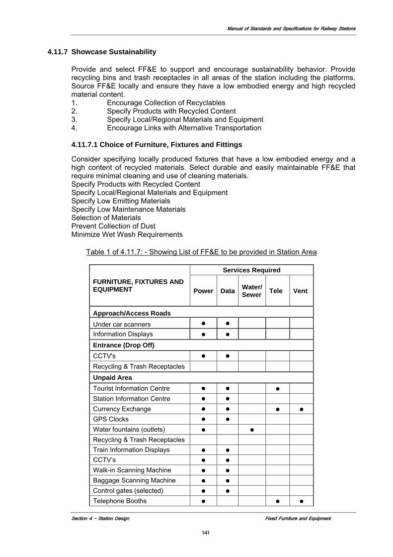
Manual of Standards and Specifications for Railway Stations
Section 4 – Station Design Fixed Furniture and Equipment
141
4.11.7 Showcase Sustainability
Provide and select FF&E to support and encourage sustainability behavior. Provide recycling bins and trash receptacles in all areas of the station including the platforms. Source FF&E locally and ensure they have a low embodied energy and high recycled material content. 1. Encourage Collection of Recyclables 2. Specify Products with Recycled Content 3. Specify Local/Regional Materials and Equipment 4. Encourage Links with Alternative Transportation 4.11.7.1 Choice of Furniture, Fixtures and Fittings
Consider specifying locally produced fixtures that have a low embodied energy and a high content of recycled materials. Select durable and easily maintainable FF&E that require minimal cleaning and use of cleaning materials. Specify Products with Recycled Content Specify Local/Regional Materials and Equipment Specify Low Emitting Materials Specify Low Maintenance Materials Selection of Materials Prevent Collection of Dust Minimize Wet Wash Requirements
Table 1 of 4.11.7: - Showing List of FF&E to be provided in Station Area
FURNITURE, FIXTURES AND EQUIPMENT
Services Required
Power Data Water/ Sewer Tele Vent
Approach/Access Roads Under car scanners ● ●
Information Displays ● ●
Entrance (Drop Off) CCTV's ● ● Recycling & Trash Receptacles
Unpaid Area Tourist Information Centre ● ● ● Station Information Centre ● ● Currency Exchange ● ● ● ● GPS Clocks ● ● Water fountains (outlets) ● ● Recycling & Trash Receptacles Train Information Displays ● ● CCTV’s ● ● Walk-in Scanning Machine ● ● Baggage Scanning Machine ● ● Control gates (selected) ● ● Telephone Booths ● ● ●
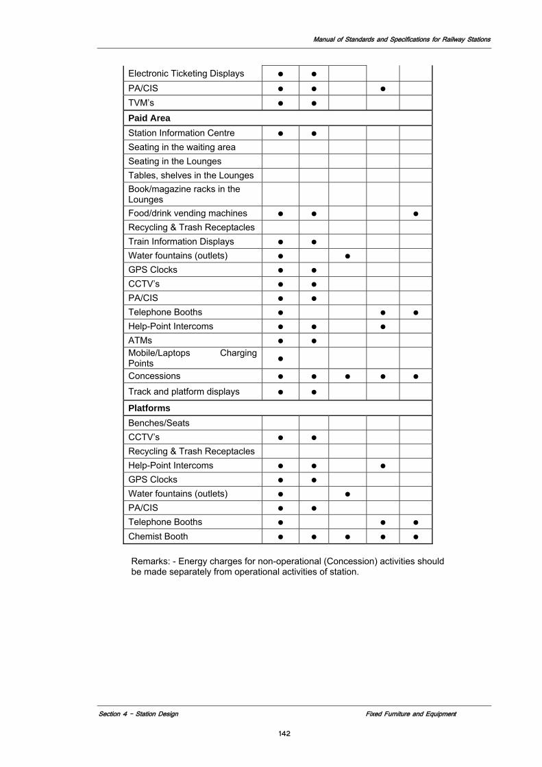
Manual of Standards and Specifications for Railway Stations
Section 4 – Station Design Fixed Furniture and Equipment
142
Electronic Ticketing Displays ● ● PA/CIS ● ● ● TVM’s ● ●
Paid Area Station Information Centre ● ● Seating in the waiting area Seating in the Lounges Tables, shelves in the Lounges Book/magazine racks in the Lounges
Food/drink vending machines ● ● ● Recycling & Trash Receptacles Train Information Displays ● ● Water fountains (outlets) ● ● GPS Clocks ● ● CCTV’s ● ● PA/CIS ● ● Telephone Booths ● ● ● Help-Point Intercoms ● ● ● ATMs ● ● Mobile/Laptops Charging Points ●
Concessions ● ● ● ● ● Track and platform displays ● ●
Platforms Benches/Seats CCTV’s ● ● Recycling & Trash Receptacles Help-Point Intercoms ● ● ● GPS Clocks ● ● Water fountains (outlets) ● ● PA/CIS ● ● Telephone Booths ● ● ● Chemist Booth ● ● ● ● ●
Remarks: - Energy charges for non-operational (Concession) activities should be made separately from operational activities of station.
Manual of Standards and Specifications for Railway Stations
Section - 5 Station Services
143
Section 5
Station Services
Manual of Standards and Specifications for Railway Stations
Section - 5 Station Services
144
5.1 GENERAL
5.1.1 This section addresses the requirements of the service portion of the Project Station. The environmental, back of house spaces and the utility and infrastructure needs for the Station Project are defined in this section.
5.1.2 Unless stated otherwise in this Manual, the work for the Project Station shall comply
with the relevant laws and regulations of the Government of India, and the State / Union Territory in which the Station is located. It shall also comply with the requirements of the State / Union Territory Public Utility Authorities, Fire Regulations and such other additional requirements as applicable for redevelopment of station according to the Manual.
5.1.3 Unless stated otherwise in the Manual the design requirements relating to sustainable
development shall be generally in accordance with LEED – Green Building Rating Systems. In the absence of any specific target called for in the following section of this manual the LEED rating target shall be a minimum of Bronze.
Manual of Standards and Specifications for Railway Stations
Section 5 – Station Service Sustainable Development & Environmental Considerations
145
5.2 SUSTAINABLE DEVELOPMENT & ENVIRONMENTAL CONSIDERATIONS
5.2.1 Introduction 5.2.1.1 Goals Indian Railways make a commitment to comply with applicable environmental laws. Within all aspects of station planning and design, consideration shall include Sustainable Development. The Concessionaire shall consider the Five Pillars of environmental sustainability in all aspects of the redevelopment and operation of any existing railway station or construction or operation of a new station: 1. Energy Efficiency 2. Material and Resource Conservation 3. Indoor Environmental Quality (IEQ) 4. Best Operations and Maintenance 5. Water Conservation and Site Management
The goal, in the application of these pillars, is to create an environmentally responsible heavy rail transit system that is appreciably ahead of current standards and practices when compared with a similar transportation system. The Railway Stations created by this effort shall become a model for a healthier, ecologically responsible environment where customers and Indian Railways staff enjoy the benefits of a “green” environment.”
This section of the Manual for Station Design and Standards addresses the ways in which these Five Pillars could be applied to the planning and design of new Railway Stations. Each of the Five Pillars is addressed in turn with Requirements that are applicable to that aim. In order to relate the requirements to specific design groups, some of the possible strategies are enumerated under each pillar. Each of these strategies is linked to a more detailed description within the strategies section in relevant sections of this document as noted. By applying such strategies to the design of Railway Stations, the designer shall demonstrate the improvements and efficiencies of the design compared to existing standards or practice with respect to the Five Pillars. 5.2.1.2 Enforcement Although significant success has been made in India in developing and enforcing environmental regulations in many areas, there still remain a number of areas that have not yet seen the promulgation of environmental standards and regulations. Many of these areas, such as the Indian Railways, have a high potential for adverse environmental impact if allowed to go unregulated. As the Ministry of Railways (MOR) undertakes to modernize its operations and facilities, it and the Concessionaire must institute and enforce adequate environmental standards to provide for the protection of the health of its clients and staff as well as the environment.
1. Environmental Impact Assessment
In response, the Concessionaire shall identify and quantify the environmental consequences of station redevelopment. The Concessionaire shall comply with all applicable Indian laws and regulations to mitigate the environmental impact from the construction/renovation activities. It should conduct a preliminary analysis (Environmental Analysis) of the environmental impact of the proposed action(s) and identify alternatives to those actions. The concessionaire will need to prepare a detailed Environmental Impact Assessment (EIA) according the requirements of the Ministry of Environment and Forests in conjunction with local authorities having jurisdiction, addressing all areas identified as having
Manual of Standards and Specifications for Railway Stations
Section 5 – Station Service Sustainable Development & Environmental Considerations
146
environmental impacts. All appropriate categories/areas, such as air quality, noise, water quality, etc. are to be considered in the environmental analysis.
2. Environmental Management System
The Indian Railways and the Concessionaire shall have in place an Environmental Management System (EMS) to ensure the management support for mitigating the environmental consequences of the operations at the world-class stations in conformance with ISO 14001. A policy statement from top management; identifying impacts and goals to mitigate them; assigning roles and responsibilities; providing appropriate and adequate training; preparing and maintaining documentation; monitoring and correcting environmental problems; and management review aimed at continuous future improvement, are the major elements of an ISO 14001 EMS, that has been widely adopted by the internationally both in government as well as the private sector, and is quite popular and well-recognized in India. The Railway Station and the Concessionaire staff should receive appropriate level of environmental training to ensure necessary knowledge, skill, and competency for understanding the environmental issues as and when they arise, and to provide solutions to meet the environmental regulations and requirements, thereby minimizing the adverse environmental consequences from the Railway Station Construction/Renovation operations.
3. Environmental Certification
The Concessionaire shall obtain certification for the project under the Leadership in Energy and Environmental Design (LEED), Green Building Rating System (USA) an internationally accepted benchmark for the design, construction, and operation of high performance energy efficient buildings. The concessionaire should aim for a Platinum level certification. If existing conditions associated with the construction of a structure over an operating railroad make it infeasible to attain a LEED’s Platinum certification the concessionaire shall document the reasons and in no case should the certification be less than the lowest LEED certification available. LEED promotes a whole building approach to sustainability by recognizing performance in the five pillars of environmental design and human health mentioned above, and provides a road map to measure and document success for energy savings
References 1. Ministry of Environment and Forests 2. National Building Code (India) 3. Bureau of Energy Efficiency BEE (India) 4. Energy Conservation Building Code (India), 2007 5. Green Building Council (GBC), USA 6. Leadership in Energy and Environmental Design (LEED), USA. 7. The Energy and Resource Institute (TERI) Recommendations and Mandates 8. World Health Organisation Guidelines for Drinking water 9. SO 9001, International Standards Organization, Standard for Quality 10. ISO 14001, International Standards Organization, Standard for Environmental
Management System 11. Occupational Health and Safety Advisory Services (OHSAS) 18001-1999 –
Occupational Health and Safety Management System 12. International Building Code (IBC)
Manual of Standards and Specifications for Railway Stations
Section 5 – Station Service Sustainable Development & Environmental Considerations
147
13. NFPA 130 – Standard for Fixed Guideway Transit and Passenger Rail Systems (USA)
5.2.2 Energy Efficiency
The ways in which energy is expended shall be examined from the earliest stages of design through the daily operation of the system. Compliance with Energy Conservation Building Code (India), 2007 shall be the minimum requirements in the event that more stringent measures are not called for in this section or in section 5.5.
5.2.2.1 Respond to Demand Optimize energy consumption by designing systems and operational strategies that respond to changes in demand. Railway Stations generally have peak patronage levels twice a day, with less patronage at off-peak times. Systems should be designed and operated to mimic the patronage curve or occupant load, producing energy savings in comparison to designing them for peak loading only.
Strategies 1. Station Configuration: Respond to Demand: Vertical Circulation Elements 2. Entrances: Showcase Sustainability: Entrances 3. Ventilation and EC: Respond to Demand: Ventilation 4. Lighting: Respond to Demand: Lighting 5. Lighting: Showcase Sustainability - Lighting
5.2.2.2 Maximize Energy Performance Employ available technologies and design/operational strategies that will provide a net reduction of 30% in the amount of energy consumed by an equivalent Railway Station that only conforms to the minimum statutory and regulatory requirements.
Strategies 1. Station Configuration: Elevator and Escalator Resource Conservation 2. Station Configuration: Respond to Demand: Vertical Circulation Elements 3. Ventilation and EC: Natural Ventilation 4. Ventilation and EC: Thermal Comfort – Design Temperature 5. Ventilation and EC: Combined Use of Fans 6. Communications: Communications Technology Review 7. Lighting: Increase Natural Light 8. Lighting: Lighting Energy Consumption Level 9. Signage: Technology Review 10. Signage: Reduce Energy Consumption
5.2.2.3 Minimize the Thermal Envelope Minimize the volume of areas to make for more efficient environmental control and maximize the level of thermal isolation.
Strategies
Ventilation and Energy Conservation: Reduce Thermal Envelope 5.2.2.4 Utilize Thermal Assets Reduce energy consumption by utilizing the thermal mass to aid environmental control. Elements, such as the concourses, platforms, tracks, major structural elements, and the surrounding earth, can be used as thermal batteries for anticipated cooling and heating
Manual of Standards and Specifications for Railway Stations
Section 5 – Station Service Sustainable Development & Environmental Considerations
148
loads. Thermal mass storage can be used to reduce energy consumption consumed in environmental control, even when it is not capable of carrying the whole load.
Strategies Ventilation and Energy Conservation: Thermal Mass Storage Ventilation and Energy Conservation: Geothermal Heat Pumps 5.2.2.5 Reduce Equipment Energy Consumption Use energy models to determine energy loads and to evaluate opportunities for reducing energy consumption as well as operational costs. All equipment to be of the highest energy star rating available in accordance with BEE Standards under Indian Energy Conservation Act (2001) MOR directive 2006/Elect. (G)/150/5
Strategies 1. Station Configuration: Elevator and Escalator Resource Conservation 2. Ventilation and EC: Ventilation Equipment Energy Consumption Level 3. Communications: Communications Technology Review 4. Communications: Reduce Thermal Pollution from equipment 5. Lighting: Reduce Lighting Energy Consumption Level 6. Lighting: Integration of Emergency Fixtures 7. Signage: Technology Review for Lowest Consumption Technology
5.2.2.6 Reduce Energy consumption Use energy modeling systems, such as DOE-2 (US Department of Energy – 2) to reduce energy consumption by a minimum of 30% against code. 1. Encourage On-Site Energy Production - Reduce the demand for energy by
employing the use of renewable energy sources supplied within the project site. An example would be providing photovoltaic panels at entrances, roof, etc.
2. Meet 10% of the peak load of the station complex by renewable energy sources. 3. Encourage Clean Energy Sources - Encourage the use of energy sources that
produce little or no pollution.
Strategies 1. Station Configuration: Elevator and Escalator Resource Conservation 2. Ventilation and EC: Ventilation Equipment Energy Consumption Level 3. Communications: Choice of Communication Equipment and Thermal Pollution
from Equipment 4. Lighting: Lighting Fixtures 5. Signage: Choice of Signage Equipment to reduce energy consumption 6. Entrances: Showcase Sustainability – Entrances 7. Lighting: Showcase Sustainability – Lighting
5.2.3 Material and Resource Conservation Selection of building material is important in sustainable design because of the extensive network of extraction, processing, and transportation steps required for processing them. Activities to create building materials pollute the air and water, destroy natural habitats, and deplete natural resources. These are also factors in the products transportation and the final disposal of the materials. Salvaged, recycled content, local and renewable materials minimize the impact of natural resource consumption.
Manual of Standards and Specifications for Railway Stations
Section 5 – Station Service Sustainable Development & Environmental Considerations
149
5.2.3.1 Efficient Material Use Plan an efficient layout that minimizes the amount of material used over the entire project. Strategies 1. Station Configuration: Optimize Vertical Circulation Elements 2. Station Configuration: Efficient Space Planning 3. Utility and Systems Interface: Optimize Plant Room 4. Utility and Systems Interface: Integration of Utilities 5. Communications: Communications Technology Review 6. Communications: Equipment Obsolesce 7. Materials and Finishes: Integration of Noise Attenuation with Structure 8. Acoustics: Integration of Noise Attenuation with Structure 9. Signage: Technology Review
5.2.3.2 Encourage Collection of Recyclables Reduce the amount of material waste generated by encouraging recycling, providing facilities and supporting public education strategies and signage.
Strategies Operations and Maintenance: O&M Plan to Address Recycling Signage: Signage to Support Recycling Initiatives FF&E: Showcase Sustainability – FF&E Institute an effective Solid Waste Management Program at the Stations
5.2.3.3 Institute an effective Solid Waste Management Program Ensuring public awareness and stiff enforcement can result in proper and adequate solid waste management system. To have world-class railway stations, the Concessionaire shall put in place an integrated solid waste management program that complies with published and/or appropriate national and local solid waste management requirements. The Program must allow for an effective management of solid waste in a way that is protective of human health and the environment, while making the station aesthetically more pleasing and acceptable to travelers and staff. The Program shall include: 1. Segregating, (separate collectors for paper, plastics and other recyclable waste
streams) storing, transporting, recycling, treating, and disposing of solid waste. 2. Storage shall be reduced where applicable by the use of solar compactors. 3. Incentives for solid waste reduction and for use of recycled and environmentally
friendly/preferable material 4. Responsibilities for the different elements of the solid waste management
program 5. Goals for future reduction in the rate of solid waste generated by using the 3R
formula (Reduce, Reuse, Recycle).
The numbers, sizes, and locations of receptacles for segregated solid waste would be in accordance with the minimum requirements included in the Indian Railways Works Manuals, The Municipal Solid Wastes (Management and Handling) Rules, 1999, Ministry Of Environment and Forests, Government of India, and the information collected during the operation of the station. The frequency of waste collection and final disposal would be decided upon consultation with the local waste management agencies and on the availability of the resources and facilities. The waste collection
Manual of Standards and Specifications for Railway Stations
Section 5 – Station Service Sustainable Development & Environmental Considerations
150
system on the platform will factor in the waste generated by trains, which are passing through the station.
5.2.3.4 Reuse Construction Waste and Conserve Resources Minimize construction waste and conserve resources. Direct all usable waste materials into the construction process and all recyclable waste materials into the manufacturing process.
Strategies Materials and Finishes: Selection of Finish Materials
5.2.3.5 Specify Products with Recycled Content Reduce the use of raw materials by specifying recycled products or those with recycled content.
Strategies 1. Station Configuration: Choice of Escalators and Elevators 2. Communications: Choice of Communication Equipment 3. Materials and Finishes: Selection of Finish Materials 4. Lighting: Lighting Fixtures 5. Signage: Choice of Signage Equipment 6. FF&E: Showcase Sustainability – FF&E 7. FF&E: Choice of Furniture, Fixtures and Fittings 8. Institute an effective Solid Waste Management Program at the Stations, which
includes a component for all recyclable waste.
5.2.3.6 Eliminate Chlorofluorocarbons (CFCs) Reduce ozone depletion by eliminating the use of refrigerants and solvents that contain CFCs and the use of insulation materials that employ CFCs in their production.
Strategies
Ventilation and EC: Natural Ventilation
5.2.3.7 Specify Local/Regional Materials and Equipment Reduce the environmental impact associated with the transportation of building materials by specifying those that have been manufactured locally.
Strategies 1. Materials and Finishes: Selection of Finish Materials 2. Lighting: Lighting Fixtures 3. Signage: Choice of Signage Equipment 4. FF&E: Showcase Sustainability – FF&E 5. FF&E: Choice of Furniture, Fixtures and Fittings
5.2.3.8 Encourage Links with Alternative Transportation Limit the use of non-renewable fuel sources and associated pollution by encouraging walking, bicycle riding, and the use of vehicles powered by alternative sources.
Strategies 1. Entrances: Intermodal Connections 2. Entrances: Showcase Sustainability – Entrances
Manual of Standards and Specifications for Railway Stations
Section 5 – Station Service Sustainable Development & Environmental Considerations
151
3. FF&E: Showcase Sustainability – FF&E 4. Power sources in parking area for electric cars. 5. Parking for bicycles
5.2.4 Indoor Environmental Quality Indoor environmental quality (IEQ) strategies include issues related to indoor air quality (IAQ), such as ventilation effectiveness and control of contaminants, illumination, acoustics, vibration, occupant control of building systems and day lighting. All of these issues have the potential to enhance the indoor environment and optimize the health, comfort and productivity of building occupants.
5.2.4.1 Occupant Control of Systems In nonpublic areas, provide occupant control of ventilation and lighting systems to support health, comfort and productivity.
Strategies 1. Ventilation and EC: Station and Facility Management System 2. Ventilation and EC: Occupant Control of Systems 3. Lighting: Respond to Demand Lighting 5.2.4.2 Effective Ventilation Employ design strategies to provide fresh air intakes that enhance the health and productivity of the Railway Station environment. Strategies 1. Ventilation and EC: Natural Ventilation 2. Ventilation and EC: Respond to Demand: Ventilation –Including use of CO2
sensors in air tempered spaces. 3. Ventilation and EC: Station and Facility Management System 4. Ventilation and EC: Air Filtration 5.2.4.3 Specify Low VOC Emitting Materials Specify materials and finishes, including flooring and furniture, that contain no known carcinogens, have low levels of volatile organic compounds (VOCs), are non toxic and chemically inert, to reduce the amount of indoor air contaminants that may be irritating or unhealthy to occupants. Strategies 1. Operations and Maintenance: Maintenance Materials 2. Ventilation and EC: Inert Materials 3. Materials and Finishes: Selection of Finish Materials 4. Signage: Choice of Signage Equipment 5. FF&E: Choice of Furniture, Fixtures and Fittings 5.2.4.4 Control Chemical and Pollutant Sources Develop methods to prevent the risk of chemical or other pollutants from being introduced into the Railway Stations. These methods include both measures employed in the design of the system and strategies used in the operation and maintenance of the system. In addition to ensuring compliance with the applicable emissions standards, provisions must also be made to minimize the environmental and health impacts of these pollutants by appropriate and available active or passive operational controls.
Manual of Standards and Specifications for Railway Stations
Section 5 – Station Service Sustainable Development & Environmental Considerations
152
Strategies 1. Station Configuration: Platform designs that would channel out of the station the locomotive and generator car exhausts. 2. Entrances: Walk-Off Grilles 3. Ventilation and EC: Air Intake Location at least 8 m away from any potential source of air contaminants. 5.2.4.5 Maximize Day lighting Implement strategies to maximize daylight. Where possible, integrate indoor space with the outdoor environment to improve the environment for occupants. Strategies 1. Entrances: Entrance Orientation 2. Entrances: Showcase Sustainability – Entrances 3. Materials and Finishes: Increase Natural Light 4. Lighting: Increase Natural Light 5. Lighting: Showcase Sustainability – Lighting 5.2.4.6 Reduce Noise and vibration. The impacted areas and the degree of noise and vibration impact shall be clearly delineated in the environmental documents, such as the Environmental Analysis or the Environmental Assessment Statement. The noise and vibration data shall be collected on site by taking measurements using acceptable equipment and data collection protocols. Appropriate prediction models shall be used, where necessary, to predict the noise and vibration levels from future operations. The environmental document will also identify any mitigation measures to meet the requisite noise and vibration standards in place. Minimize the amount of noise and vibration generated by selecting quieter equipment and technologies. Strategies 1. Ventilation and EC: Noise Attenuation 2. Materials and Finishes: Integration of Noise Attenuation with Structure 3. Acoustics: Integration of Noise Attenuation with Structure 4. Acoustics: Rubber sound absorbing pads below rails and sleepers in station areas.
5.2.5 Operations and Maintenance Modern Railway Stations are highly complex structures, both physically and technologically. They must serve the needs of the traveling public during normal and emergency situations and must be operable and maintainable with minimal resources.
A holistic approach requires a design strategy that optimizes energy efficiency. Efficient operations and maintenance will require performance monitoring coupled with active progressive maintenance programs. These will need to take advantage of the data that is available from each of the systems, and be centrally monitored. The Indian Railways stations operate 24 hours a day, 7 days a week, 365 days a year. Therefore, the materials and finishes in the stations must be durable and easily maintained and allow repair/replacement with minimal/no shutdown of service.
Manual of Standards and Specifications for Railway Stations
Section 5 – Station Service Sustainable Development & Environmental Considerations
153
5.2.5.1 Specify Low Maintenance Materials Specify materials that require minimal maintenance during lifespan to conserve cleaning resources and enhance durability. Painted surfaces are discouraged at new stations, and materials shall have a minimum life cycle of 35 years (50 years where possible). Materials should be locally sourced where possible.
Strategies 1. Operations and Maintenance: Maintenance Materials 2. Materials and Finishes: Selection of Finish Materials 3. Signage: Selection of Materials 4. FF&E: Choice of Furniture, Fixtures and Fittings
5.2.5.2 Commission Systems and Equipment Ensure that the building systems operate efficiently as intended through periodic testing and calibration.
Strategies 1. Ventilation and EC: Station and Facility Management System 2. Communications: Commissioning Communication Systems
5.2.5.3 Station Systems Monitoring 1. Provide a permanent monitoring system to provide feedback for the comparison,
management, and optimization of equipment for energy efficiency. 2. Provide an ongoing system to guarantee accountability for maintaining
performance standards in the operation and maintenance of the Railway Stations.
Strategies 1. Operations and Maintenance: Performance Monitoring 2. Ventilation and EC: Station and Facility Management System 3. Utilities and Systems interface: Station Systems Monitoring – Utilities 4. Communications: Performance Monitoring – Communications
5.2.5.4 Selection of Materials Select durable and easily maintainable finishes. Select maintenance materials (e.g., lubricants) that are environmentally friendly.
Strategies 1. Operations and Maintenance: Maintenance Materials e.g. Biodegradable
Lubricants for Escalators and Elevators, cleaners and solvents for maintenance 2. Communications: Choice of Communication Equipment e.g. UPS system 3. Lighting: Lighting Fixtures and Lamps
5.2.5.5 Prevent Collection of Dust Design forms and equipment that require minimal cleaning.
Strategies 1. Materials and Finishes: Design for Ease of Maintenance 2. FF&E: Choice of FF&E
Manual of Standards and Specifications for Railway Stations
Section 5 – Station Service Sustainable Development & Environmental Considerations
154
5.2.6 Water Conservation & Site Management Water should be used efficiently as a resource. The impact of water use and discharge on the local ecology should be considered. When reviewing site alternatives, it is important to consider environmental criteria throughout the site selection process. The major ecological features of the site should be identified, including the site geology, hydrology, vegetation, wildlife, and prior site history.
5.2.6.1 Water Use and Wastewater Reduction Select efficient equipment and methods to minimize the use of water and production of wastewater.
Strategies 1. Operations and Maintenance: O&M Plan to Address Water Management,
including a water conservation plan to minimize avoidable water losses (e.g., leaks)
2. Materials and Finishes: Minimize Wet Wash Requirements 3. FF&E: Minimize Wet Wash Requirements 4. Rainwater harvesting 5. Waste water recycling 6. Waterless Urinals and low water usage flushing
5.2.6.2 Potable Water Supplies The Concessionaire shall select the best option to provide high quality drinking water at all times. Water supply for municipality shall be monitored to ensure potable water is provided at the station meets the standard called for in this section. Concessionaire shall provide in-house water treatment systems at the stations. The drinking water quality shall meet the potable water standards established by World Health Organization (WHO) Guidelines for drinking Water ISBN 924 1546387 and the Indian Bureau of Standards IS 10500 - 1991. The same high quality water can then be supplied on the trains, further eliminating the need for storage of bottled water on the trains and disposal of the plastic bottles. The Concessionaire shall meet the Packaged Water standards established by the Bureau of Standards, in order to improve the customer faith and confidence in the water supplied at the Railway Stations, and to eliminate the use of bottled water.
The Concessionaire shall perform daily water quality monitoring required under the Bureau of Standards requirements, and display the results of the monitoring for public viewing.
Water conservation measures shall be put into place to the maximum extent possible. The high quality of drinking water and minimal water loss will be the hallmarks of the Indian Railways’ efforts to modernize the Railways’ facilities to make the experience for its clients – the passengers – a memorable one. A world-class railways station built using the guidance in this Manual will provide the Indian Railways with that opportunity. Water supply points should be scattered throughout the station in order for the passengers and staff to fill their own containers, thus minimizing the need for disposal of plastic water bottles. Adequate number of water taps shall be provided in conformance with the current Indian Railways Works Manuals for Drinking Water Supplies at Railway Stations.
Strategies 1. Operations and Maintenance: O&M Plan to Address Proper Operation of Water
Treatment System, and for adequate monitoring of water quality
Manual of Standards and Specifications for Railway Stations
Section 5 – Station Service Sustainable Development & Environmental Considerations
155
2. Materials and Finishes: Use system with low energy and maintenance requirement
5.2.6.3 Wastewater Management Select methods for wastewater collection that would be cost-effective and protective of human health and environment. Separate collection and treatment systems shall be used for domestic wastewater and storm water/gray water. Domestic wastewater will comprise of: the waste generated from the sanitary facilities at the Stations, and that is generated from the tracks during cleaning of the toilets. The sanitary sewage shall be discharged into the station wastewater treatment system. Treated water to be used for ventilating and air conditioning system, fire fighting and landscaping, with remainder if any to be discharged into the public sewer system. The collection systems shall be so designed as to make the entire Railway Station area aesthetically pleasing – no visible collection pipes, no ponding, stagnant water at the platforms and other areas of the Station, clean and functional toilet facilities, hidden, as far as possible and practical, and easy to access and clean storm water collection system.
Both Indian and Western style toilet facilities shall be provided at all stations. All toilet facilities at the Railway Stations shall be inspected and cleaned once every hour, and the results recorded on forms developed by the Concessionaire and approved by the MOR Representative. The Concessionaire shall provide disposable toilet seat covers for all western toilets within the Concession.
Strategies 1. Operations and Maintenance: O&M Plan to Address Proper Operation of Waste
Water Treatment System, and for adequate monitoring of water quality 2. Materials and Finishes: Use system with low energy and maintenance
requirement
5.2.6.4 Storm Water and Gray Water Management Ensure proper management of storm and gray water to optimize the use of treated storm and gray water for specific purposes, e.g., track and carriage cleaning. Storm water will be collected separately in an open or closed storm water system and mixed with the gray water from kitchens and laundries at the station. The collection system will allow the storm water to be by-passed during times of heavy rain to avoid overloading the treatment system. The mixed effluent will be treated using a packaged treatment plant (bar screen, oil/water separation, flocculation, coagulation, sedimentation, and disinfection, similar to that currently practiced at the Mumbai Terminus). The degree of treatment must be such as to ensure meeting water re-use standards, as the water is likely to come into human contact when cleaning carriages and tracks.
Strategies 1. Operations and Maintenance: O&M Plan to Address Proper Collection,
treatment, and reuse of storm and gray water, and for adequate monitoring of the quality of the treated water
2. Materials and Finishes: Use system with low energy and maintenance requirement.
5.2.6.5 Reduce Heat Islands on Above-Ground Roofs Design the roofs of above-ground structures to minimize the “heat island” effect. This may only be applicable at entrances.
Manual of Standards and Specifications for Railway Stations
Section 5 – Station Service Sustainable Development & Environmental Considerations
156
Strategies Entrances: Roof Gardens
5.2.6.6 Minimize Thermal Pollution Employ methods and means to minimize the amount of thermal pollution put into the air, water and earth.
Strategies 1. Ventilation and EC: Ventilation Equipment Energy Consumption Level 2. Ventilation and EC: Reduce Thermal Envelope 3. Ventilation and EC: Respond to Demand: Ventilation 4. Ventilation and EC: Geothermal Heat Pumps 5. Communications: Thermal Pollution from Equipment 6. Lighting: Respond to Demand: Lighting 7. Lighting: Lighting Energy Consumption Level
Manual of Standards and Specifications for Railway Stations
Section 5 Station Services Parcel Storage and Movement
157
5.3 PARCEL STORAGE AND PARCEL MOVEMENT
5.3.1 Introduction In the current operation MOR distributes mail and parcels through their transport in rail cars at each end of a train. It involves the transport of parcels to and from the designated train compartments through the station complex. This operation requires significant amount of handling of the parcels and storage at the station complex. Major components of this activity are storage, access, and handling. The current arrangement causes inconvenience to the passenger by obstructing traffic flows and completely compromises the security and safety of the passenger operation. Furthermore, there are no provisions for the safe and secure handling of the parcels themselves independent of the passenger operation. The Concessionaire shall evaluate the removal of this activity form the passenger station operation and incorporation of the same into the freight operation of the railways, whose procedures and protocols are more consistent with the handling and distribution of parcels. To maintain this activity in the MOR passenger operation requires a complete reorganization of the parcel operation. It will require in effect an extension to existing stations and the creation in new stations of a separate and distinct parcel operation that operates completely independent of the passenger section of the station and is physically separated. It is essential to separate this activity both operationally and physically from passenger activity to achieve an acceptable measure of security for passenger.
5.3.2 Requirements 5.3.2.1 Space and Infrastructure The parcel operation includes RMS, which has separate storage and material handling requirements, and parcel movement, which includes both MOR and outsourced vendors operating out of the same space. The Concessionaire must perform a materials handling analysis that quantifies the material streams for these three different sources, their respective reception and delivery procedures and make a projection on the current and horizon design year requirements for these operations. Analysis should include provisions for mechanized material handling automated origin and destination identification and computer based monitoring of package receipt, storage and delivery such as electronic tracking system using available scanning technology. The result of this analysis which shall be shared with MOR should provide space and infrastructure requirements that need to be incorporated into the station design for the installation of the parcel operations. Parcel handling analysis should take into account the use of latest emerging technology such as RFID (Radio frequency identification) which streamlines the scanning process with the use of wireless electronic scanning.
Manual of Standards and Specifications for Railway Stations
Section 5 Station Services Parcel Storage and Movement
158
5.3.2.2 Management The management of the movement of these parcels requires dedicated staff separate from the operation and maintenance of the station. MOR and the outsourced vendor and RMS will manage this operation. The Concessionaire shall provide the storage, material handling, reception and delivery and office and staff support spaces and infrastructure (exclusive of material handling equipment) for this operation.
5.3.3 Configuration In order to minimize the impact this operation has on the passenger activity, the parcel operation shall be centralized on one side of the station. Parcels received on the opposite side shall be unloaded moved to a non-passenger concourse or access way and delivered to the parcel side. 5.3.3.1 Design The Concessionaire shall consider the following for the creation of an effective and efficient parcel storage and movement system: 1. Designated station areas including platforms to accommodate vehicular
transport of parcels from trains to storage areas and vice versa. 2. Assessment of all plausible alternatives for the handling of parcel storage and
movement-related functions, e.g., provision of over- or sub-way access from one platform to the other to permit concentration of parcel area in one location; lifts for parcels, etc., and adoption of the best alternative.
3. Consolidation of all parcel operations in a central parcel handing complex. 4. Provision of a train information display at the central parcel-handling complex. 5. Security compartmentalization of parcel area from the rest of the station to
permit complete isolation of any potential risk to the passengers in the event of a safety or security incident in the parcel area.
6. Compliance with all applicable fire and life safety codes. 5.3.3.2 Circulation Access to the station for parcels and within the station shall be separate from all other circulation. Following are the general requirements: 1. Vehicular access can be common; however, loading ports for parcels should be
separate and configured with adequate space so as not to interfere with other vehicular traffic.
2. Staff access can be with other station staff, but parcel area within the station will be accessible only to Parcel staff.
3. Circulation between platforms for parcel handling shall be planned to minimize potential conflict with train operation, e.g., use of over-ways and sub-ways, wherever feasible. In large stations with intensive and continuous parcel volumes, mechanized transportation shall be considered.
4. Mechanized loading and unloading of parcels to and from the train
5.3.4 Adjacencies The parcel section, which includes the RMS and all outsourced parcel vendors, shall have a physical separation on the platform essentially dividing all passenger operations. Location of parcel area will be at one end of the platform essentially operating as a separate station with its own vehicular access and pedestrian access. Spaces will house storage and administrative spaces and be provided with toilets as required. All staff facilities should also be separate except that in smaller stations consideration shall be
Manual of Standards and Specifications for Railway Stations
Section 5 Station Services Parcel Storage and Movement
159
given to the consolidation of the staff facilities with the remainder of the station staff for space and cost effectiveness. These spaces will include but not be limited to:
5.3.4.1 Parcel Receipt and Distribution Space will house activity that checks in and out all parcels coming into or going out of the station. This operation may involve coordination with private vendors and RMS, which could result in the creation of separate receipt structures or compartmentation of one central structure. Provision shall be made for electronic tracking of parcels in this area.
Location – in parcel area adjacent to platform and at the parcel loading dock at the service street side of the station. Features– Enclosed, vented, secure and fire rated with extensive telecommunications capacity
5.3.4.2 Parcel Storage Space to house parcels pending final distribution. This will be in the form of separate structures or one larger structure compartmentalized for each of the vendors and RMS working in the station. These will be the responsibility of the respective vendors who will have to provide their own locking and other security provisions, as they deem appropriate.
Location – in parcel area. Features– Enclosed, vented, secure and fire rated.
5.3.4.3 Parcel Handling Equipment In some instances the extent of parcels to be managed may require specialized handling equipment, such as conveyer belts and or overhead carriers. This will involve provision of space and facilities for the installation and if necessary storage of this equipment.
Location – in parcel area adjacent to platform. Features– Enclosed, and secure.
5.3.4.4 Administration Office Space to house MOR staff responsible for overseeing parcel operation. It will also be the communications center for the parcel operation at the station and between stations.
Location – in parcel area. Features– Enclosed lighted and vented spaces by natural and mechanical means as appropriate; toilet facilities. Structure should be secure. Provisions for telecommunications
Manual of Standards and Specifications for Railway Stations
Section 5 – Station Services Support Service Area 160
5.4 SUPPORT SERVICE AREAS
5.4.1 Introduction
The spaces at a station that are not directly involved in the movement of passengers have different functional and construction requirements. They comprise of all the support facilities for the MOR train management and Concessionaire station operations staff, along with all required storage, infrastructure, control, security and administrative spaces. They should relate as directly as possible without interfering with the passenger operation to their main functional areas of operation. The Concessionaire will need to prepare a staffing analysis of the station requirements which shall incorporate staffing MOR assign to train and security operations at each station. Staffing required for the parcel storage and movement, and staffing required by the concessionaire to manage the station and assume all the responsibilities outlined in section 2.8 of this manual and outlined in the Concession Agreement. Based on this analysis a program that details the space and support infrastructure requirements to accommodate this staff will be submitted to MOR for their review and approval. The station design will use this program along with the other requirements spelled out in section 4.5 of this manual as the basis for the station design. Following is a listing of the type of spaces and requirements that are indicative of what needs to be provided in the program. Also included is a sample list of support spaces (back of house) existing in one of the main stations. This list is not comprehensive but is provided for information purposes and to highlight where these space requirements will involve operational considerations to be provided by MOR. All support space areas will require train information displays relevant to the specific operation. As part of the Concessionaire’s analysis a determination of appropriate electronic train information required in each of the stations main operational areas (e.g. maintenance, platform services, catering) shall be made and the appropriate equipment incorporated into the station design. References National Building code of India Indian Railway Works Manual(IRWM), 2000 Section 6: - Operations and Maintenance
5.4.2 STAFF Station Staff includes all MOR staff both at the station and coach staff that requires temporary facilities at the station, Concessionaire’s staff and any other government or private entity with staff assigned on a full time basis to the station. As part of the design of the station, an analysis will be prepared and reviewed with MOR that determines the estimated extent and type of staff projected for the station based on its projected capacity. MOR will approve staff assumptions for all staff under its direct supervision which for the purposes of this manual includes all parcels and the Rail Mail Service (RMS) staff. Unless specifically proscribed elsewhere in this manual, staff facilities shall to the extent possible be combined for efficiency and cost effectiveness. 5.4.2.1 Lockers Locker facilities will consist of locker rooms and toilets. There shall be separate locker rooms for males and females in a proportion as determined in the staffing analysis and approved by MOR. One locker for each of the station staff member should be provided.
Manual of Standards and Specifications for Railway Stations
Section 5 – Station Services Support Service Area 161
The size of locker facility should be at par with the status and work requirement of the staff person. Exclusive toilet / drinking water facility for the station staff with provisions as per the standards laid out in IRWM, 2000. Showers are to be provided on a limited basis for train crews and their use shall be limited to that particular staff group. Provisions should be made in the design for limiting the use of the showers to designated staff.
Location – non-public areas Features – Enclosed and vented spaces by natural and mechanical means as appropriate
5.4.2.2 Eating /Lounge Area Space should be provided for station staff to take their meal breaks. Extent of space required will be determined by the staffing analysis.
Location – non-public areas, near or adjacent to locker areas Features – Enclosed lighted and vented spaces by natural and mechanical means as appropriate. Space shall be equipped with limited kitchen type facilities (sinks, stoves, and storage) for limited preparation and consumption of food.
5.4.2.3 Toilets In addition to separate male and female congregate toilet facilities at locker areas, toilets for staff will be provided throughout the station non-public areas. The extent will be determined by the staffing analysis but at a minimum there shall be one for each sex available for each platform and at all major station entrance support areas.
Location – non-public areas Features – Enclosed lighted and vented spaces by natural and mechanical means as appropriate. Plumbing and fixtures as required.
1. Water Closets = Males – One for every 20 persons or part thereof
a) Females - One for every 10 persons or part thereof b) 30% of total W/C should be European style
2. Ablution Taps One in each water closet with special arrangement of hot / cold
water. 3. Urinals -Nil up to 5 person
a) 1 for 6 to 15 persons b) 2 for 16 to 35 persons c) 3 for 36 to 60 persons d) 4 for 61 to 80 persons e) From 81 to 150 persons add @ 3.5% f) From 151 persons add @ 3.0%
4. Wash Basins - One for every 15 persons or part thereof
5. Drinking water fountain - One for every 75 persons with minimum of 2 at each floor (Water treated to meet requirements of section 5.2.6.2)
6. Cleaners Sink - Two per floor minimum preferably in or adjacent to sanitary
rooms.
Manual of Standards and Specifications for Railway Stations
Section 5 – Station Services Support Service Area 162
5.4.3 Station Management Spaces associated with the management of the station include all control, security, and administrative spaces required for the management of the station. MOR will issue to the concessionaire a list of required track and train operation spaces and their requirements to include as part of the design. The other spaces noted here will be determined by the design of the station. 5.4.3.1 Station Control These areas house both in the station and in the track and platform areas as part of the station structure and in stand alone structures, the management of station, train information, signaling, train communications, coach inspection, and train controls. MOR will provide a list of operational requirements to the Concessionaire for inclusion in the design. Communication between stations and within this station is all controlled through these locations. Layout should incorporate all appropriate separations and compartmentation for this type of operation
Location – near platform preferably straddling several platform areas. Features – Enclosed lighted and vented spaces by natural and mechanical means as appropriate; toilet facilities. Structure should be secure and fire rated with major communications installation. Emergency power shall be required.
5.4.3.2 Station Security These spaces are for the administration of the station security operations as well as the coordination of railway security and local police and fire safety operations. It will house the Government Railway Police (GRP), and the Railway Protection Force (RPF). Additional space, as approved by the MOR, will be provided to serve as the staging or response area for the Emergency Preparedness staff(s). MOR will provide a list of operational requirements to the Concessionaire for inclusion in the design. It will involve monitoring of the CCTV system and all emergency and fire safety communications systems for the station. In a large station additional security offices may be required (See section 4.2.3 and 4.2.4).
Location – near main station entrance, in large station a second security office may be required. Features – Enclosed lighted and vented spaces by natural and mechanical means as appropriate; toilet facilities. Structure should be secure and fire rated with major communications installation. Emergency power shall be required.
5.4.3.3 Administration offices Station manager and staff, medical and health inspection staff and other designated staff will be housed out of these spaces.
Location – near main station entrance and located to facilitate monitoring all station operations and be easily accessible to station staff. Features – Enclosed lighted and vented spaces by natural and mechanical means as appropriate; toilet facilities. Structure should be secure.
5.4.3.4 Train Passenger Services
While the stocking of the coaches with food and sleeping supplies generally takes place near the terminus of the trains route where the washing lines are there will be a need service the train at the stations for resupply. These activities require space in the non-
Manual of Standards and Specifications for Railway Stations
Section 5 – Station Services Support Service Area 163
passenger portion of the station and in some cases satellite facilities will be required at the platform for the efficient provision of the services. 1. Catering Main food preparation facilities will be near the washing lines however the station will need to accommodate the following:
a) Provide on departure concourse a minimum of 4 food kiosks; 5.5 square meters in size for hot take away, hot and cold food and beverage.
b) Provide on departure concourse a 465 square meter food plaza with a with a 275 square meter food preparation area.
c) On the platform provide 6 catering stalls 5.5 square meters in size for through trains. End platforms can have 5 stalls.
2. Bedroll Services Passengers in various tiers for certain types of trips are entitled to linens, blankets and pillows. Most of this supply removal operation is done at the terminus. However, space will be required in station support areas for storage of both fresh and used supplies. Concessionaire will be required to make an analysis of this operation to determine space needs at the station and how to minimize the movement of these supplies into the passenger areas. Study should include operational review of pick up and delivery, equipment requirements for efficient operation, supply and equipment storage and staff support spaces. 3. Luggage Storage Passengers with significant wait times for changing trains will require secure temporary storage of luggage. This will be provided by both staffed luggage storage counters and storage areas and luggage lockers, which will be supervised by the luggage storage staff. Administration of this area shall be done in conjunction with station security staff, which will have responsibility for overseeing this operation. The determination of the size of these facilities will require that as part of the station designers analysis of passenger capacity the profile shall include study of the utilization of these services. Location of luggage storage areas shall be in proximity to the main street access points to the station in the paid concourse areas.
5.4.4 Maintenance and Operations Spaces Station operation requires facilities for the cleaning and maintenance of the station. These are spaces distributed throughout the station. Number and size of these spaces will be determined by the design.
5.4.4.1 Operations Equipment used to maintain and manage the train operations, platform operations, and concourse operations will require storage and access to the critical areas of their respective station operations. 1. Train Operations Supplies and equipment for the train support maintenance such as lighting, tools, replacement parts and equipment for transport and delivery of same need to be housed in proximity to these operations with access that minimizes or eliminated changes in levels
Location – Near platforms, concourse or tracks Features – Enclosed, secure
Manual of Standards and Specifications for Railway Stations
Section 5 – Station Services Support Service Area 164
2. Station Operations Equipment and storage required to maintain station such as repairs, preventive maintenance and routing servicing of station plant throughout the passenger areas including platforms.
Location – Near concourse, and platforms Features – Enclosed, secure
5.4.4.2 Cleaning and Supplies Sanitation and associated maintenance requirements need spaces distributed broadly throughout the station. Both supplies and equipment should be located so as to maximize the efficiency with which the station maintenance staff can keep the facility clean and in a state of good repair. 1. Station Cleaning This space provides for storage of any mechanical equipment required for the cleaning of the station public areas including platforms, waiting areas and circulation spaces. Location – in or adjacent to public areas.
Features – Enclosed, secure.
2. Supply Storage This space provides for storage of cleaning supplies. It will include liquids and dry goods and provisions should be made for the appropriate separation of these products to ensure safe compatibility of the stored materials.
Location – in non-public areas. Features – Enclosed, fire rated, secure.
3. Fixture Supply Storage This space provides for storage of materials and supplies (e.g., lamps, bathroom replacement fittings, miscellaneous fasteners) associated with the routine maintenance of the station. Items may include lamps for light fixtures, and replacement fittings for toilets.
Location – in non-public areas. Features – Enclosed, secure.
4. Janitors Closet Number of janitor’s closets will be determined by the design. There should be a minimum of one per platform and one near each major station entrance.
Location – in public and non-public areas as required. Features – Enclosed, plumbing.
5.4.5 Utility and Infrastructure
The utility spaces required will be determined by the design of the infrastructure. MOR will provide the Concessionaire with a list of spaces and requirements to be constructed in the station complex to accommodate support railway equipment and installations. These spaces will include but not be limited to:
5.4.5.1 Electrical Service Rooms Spaces to house electrical service connections, transformers, meters and main distribution panels.
Manual of Standards and Specifications for Railway Stations
Section 5 – Station Services Support Service Area 165
Location – in non-public areas adjacent to the local service connection. Features – Enclosed, secure, vented and fire rated.
5.4.5.2 Electrical Equipment Rooms Spaces to house sub-panels, UPS, emergency generation equipment and all other electrical equipment associated with the operation of the station including, fire safety and security control rooms.
Location – in non-public areas adjacent to Service Room as required Features – Enclosed, secure, vented and fire rated.
5.4.5.3 Mechanical Equipment Rooms Spaces to house all environmental equipment, such as compressors, ventilation fans, air intake, air handling, heating equipment, cooling towers and all other heating, venting and cooling equipment that requires enclosed space. All other spaces associated with these functions including control rooms for environmental control and monitoring.
Location – in non-public areas adjacent to roof or exterior walls as required. Features – Enclosed, secure vented and fire rated as required. Plumbing as required for water and coolant systems.
5.4.5.4 Plumbing Service Rooms Spaces to house main plumbing connections for water and sanitary including pumps, main cutoff and check valves and distribution connection and systems
Location – in non-public areas adjacent to the local service connection. Features – Enclosed, secure
5.4.5.5 Sewage/Fire Suppression Service Rooms Spaces to house recirculation equipment, sprinkler and standpipe connections, equipment for sewage collection and treatment and storm/gray water collection, storage and treatment.
Location – in non-public areas adjacent service room as required. Features – Enclosed, secure vented and fire rated as required.
5.4.5.6 Train Control Rooms MOR will provide specific requirements for spaces associated with the operation of the trains that need to be located in the station. These may include signal rooms, control equipment rooms etc.
Location – As per direction of MOR. Features – Enclosed. Vented and fire rated as required.
5.4.5.7 Equipment Storage Spaces to house tools, spare parts back up equipment and transporting equipment for the servicing of the mechanical and electrical service and equipment rooms.
Location – in non-public proximate to service and equipment rooms. Features – Enclosed, secure.
5.4.6 Programmatic Requirements for Support Areas The following programmatic data are provided as an example of typical requirements for station support areas in an underground station and is intended only as an aide in preliminary station planning. The list of support areas is not necessarily complete, nor will all the support areas identified necessarily be used in every station. Actual
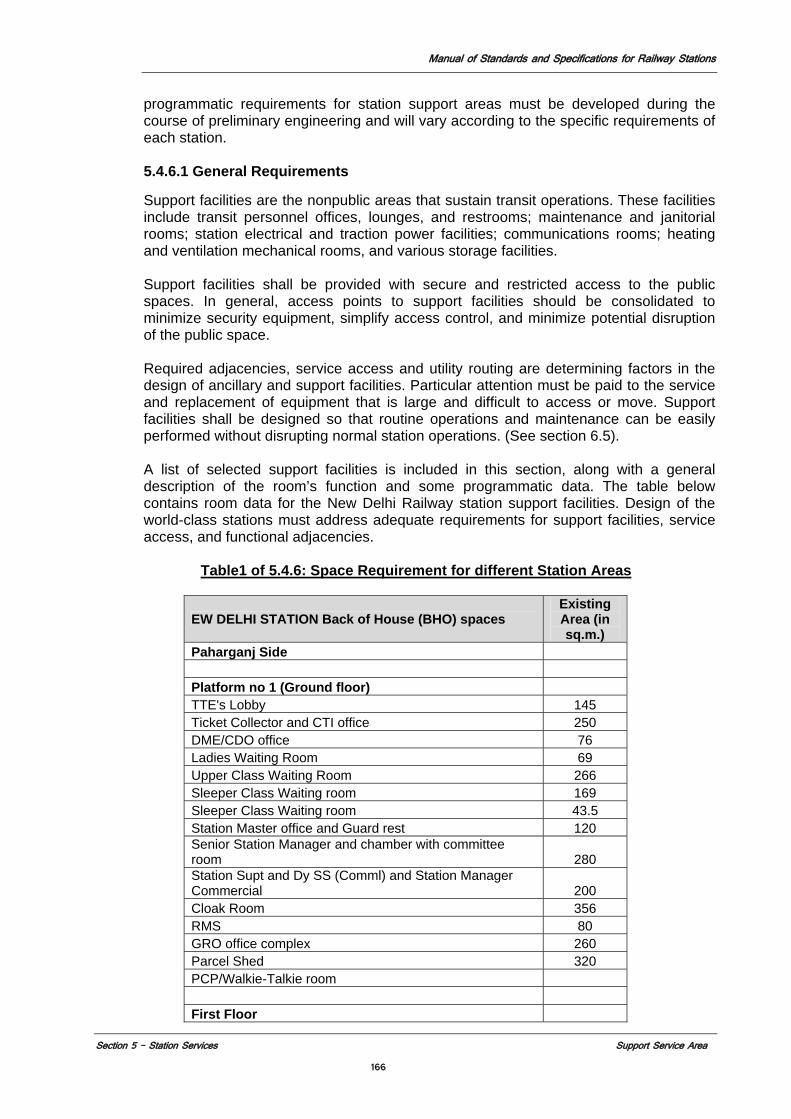
Manual of Standards and Specifications for Railway Stations
Section 5 – Station Services Support Service Area 166
programmatic requirements for station support areas must be developed during the course of preliminary engineering and will vary according to the specific requirements of each station.
5.4.6.1 General Requirements Support facilities are the nonpublic areas that sustain transit operations. These facilities include transit personnel offices, lounges, and restrooms; maintenance and janitorial rooms; station electrical and traction power facilities; communications rooms; heating and ventilation mechanical rooms, and various storage facilities. Support facilities shall be provided with secure and restricted access to the public spaces. In general, access points to support facilities should be consolidated to minimize security equipment, simplify access control, and minimize potential disruption of the public space. Required adjacencies, service access and utility routing are determining factors in the design of ancillary and support facilities. Particular attention must be paid to the service and replacement of equipment that is large and difficult to access or move. Support facilities shall be designed so that routine operations and maintenance can be easily performed without disrupting normal station operations. (See section 6.5). A list of selected support facilities is included in this section, along with a general description of the room’s function and some programmatic data. The table below contains room data for the New Delhi Railway station support facilities. Design of the world-class stations must address adequate requirements for support facilities, service access, and functional adjacencies. Table1 of 5.4.6: Space Requirement for different Station Areas
EW DELHI STATION Back of House (BHO) spaces Existing Area (in sq.m.)
Paharganj Side Platform no 1 (Ground floor) TTE's Lobby 145 Ticket Collector and CTI office 250 DME/CDO office 76 Ladies Waiting Room 69 Upper Class Waiting Room 266 Sleeper Class Waiting room 169 Sleeper Class Waiting room 43.5 Station Master office and Guard rest 120 Senior Station Manager and chamber with committee room 280 Station Supt and Dy SS (Comml) and Station Manager Commercial 200 Cloak Room 356 RMS 80 GRO office complex 260 Parcel Shed 320 PCP/Walkie-Talkie room First Floor
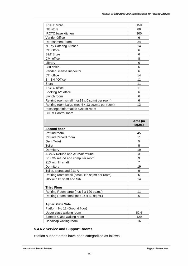
Manual of Standards and Specifications for Railway Stations
Section 5 – Station Services Support Service Area 167
IRCTC store 150 ITB store 80 IRCTC base kitchen 300 Vendor Office 6 Refreshment room 24 N. Rly Catering Kitchen 14 CTI Office 6 S&T Store 6 CMI office 8 Library 6 CHI office 6 Vender License Inspector 6 CTI office 14 Sr. SN / Office 11 Store 11 IRCTC office 11 Booking A/c office 6 Switch room 6 Retiring room small (nos18 x 6 sq mt per room) 6 Retiring room Large (nos 4 x 13 sq.mts per room) 13 Passenger information system room CCTV Control room Area (in
sq.m.) Second floor Refund room 45 Refund Record room 11 Gent Toilet 5 Toilet 5 Dormitory 19 ACM/I/ Refund and ACM/II/ refund 3 Sr. CM/ refund and computer room 3 213 with lift shaft 7 Dormitory 19 Toilet, stores and 211 A 9 Retiring room small (nos10 x 6 sq mt per room) 6 205 with lift shaft and S/R 14 Third Floor Retiring Room-large (nos 7 x 120 sq.mt.) 11 Retiring Room-small (nos 14 x 60 sq.mt.) 6 Ajmeri Gate Side Platform No 12 (Ground floor) Upper class waiting room 52.6 Sleeper Class waiting room 129 Handicap waiting room 16
5.4.6.2 Service and Support Rooms Station support areas have been categorized as follows:
Manual of Standards and Specifications for Railway Stations
Section 5 – Station Services Support Service Area 168
Electrical systems (ES) rooms (includes Traction Power) Signal rooms Station operations rooms Infrastructure rooms Ventilation rooms Plumbing and fire protection rooms Maintenance rooms Communications Data equipment rooms Passenger information room Server room Train cleaning facilities Clean train facilities Dispatcher’s Office Tower/CBTC Workstation Signal Workshop Track Lubrication Room Requirements for specific terminal stations shall be developed during the course of preliminary engineering based on project-specific requirements. The following programmatic information is for preliminary planning purposes only. Room sizes and other requirements are determined by equipment and other factors unique to each station and must be developed in conjunction with the overall station design. 1. Electrical Systems (ES)
a) Electrical Distribution Rooms (EDR) i) Function: Contains breakers and switchboards; functions as a
panel room for the floor on which it is located. ii) Location/Adjacencies: Located at each end of the station. Power
feeders (cables and conduit) from this room connect to panels and transformers located in the Electrical Panel Room (EPR) for further distribution.
b) Collector Bus Rooms (CBR) i) Function: Contains transformers that collect high voltage power
and charge the EDR. ii) Location/Adjacencies: Located adjacent to station power rooms,
at either end of the station, except on floors with an EDR. c) Electrical Panel Rooms (EPR)
i) Function: Contains electrical panels that feed a given level. Power from panels in this room feed all station power (lighting, fans, elevator and escalator motors, communication equipment, computers, fare card vending machines, etc.).
ii) Location/Adjacencies: One EPR is required at each end of the station. These rooms shall be located on the same level as the EDR.
Uninterruptible Power Supply (UPS) and Battery Room i) Function: Supplies backup power for lights, signal and
communication equipment, alarm systems, etc. Contains battery racks, UPS (rectifier/inverter) to convert power from AC to DC and from DC to AC, bypass switch and emergency switchboard.
ii) Location/Adjacencies: Typically one room is required at each end of the station.
Manual of Standards and Specifications for Railway Stations
Section 5 – Station Services Support Service Area 169
2. Station Operations
a) Station Cleaner’s Storage Room Function: Storage for wet cleaning supplies.
b) Replacement and Spare parts Function: Storing emergency spares for coaches and locomotives
c) Train lighting rooms Function: Storage of supplies and equipment and staff rooms for train lighting staff
d) Air Conditioning rooms Function: Storage of materials and equipment and staff rooms for air conditioning staff
e) Rolling stock Operation room Function: Storage of materials and equipment and staff rooms for rolling stock staff
f) Electrical General Services Room Function; Storage of materials and equipment and staff rooms for electrical general services staff
g) Shatabd/Rajhani/Specials operations and maintenance room Function; Storage of materials and staff rooms for staff to attend to Shatabd, Rajhani, and Specials
h) Janitor’s Closet Function: Houses cleaning facilities for the station.
i) Refuse Storage Room Function: Stores collected refuse prior to disposal.
j) Cleaning Equipment Room Function: Contains storage area for floor mechanical cleaning equipment to maintain station’s public areas and includes Janitor’s Closet.
k) Staff Locker Room Function: Contains toilet, shower, and locker facilities for station staff.
l) Staff Lunch Room Function: Contains kitchen and lounge facilities for station staff.
3. Infrastructure
Elevator Machine Rooms Function: Houses equipment for elevators. Escalator Machine Rooms Function: Houses equipment for external drive escalators.
a) Station Ventilation Rooms The primary function of the station ventilation system is to supply and exhaust air by means of an environmental control system. It may also be used to extract smoke in an emergency. Chiller and Ventilation Rooms Function: Contains station air-tempering equipment, including air handler units, condenser pumps, chilled water pumps, chiller plant and miscellaneous equipment.
b) Ventilation The function of the ventilation system is twofold: to reduce the heat in and to provide smoke extraction in an emergency situation.
Manual of Standards and Specifications for Railway Stations
Section 5 – Station Services Support Service Area 170
c) Plumbing and Fire Protection i) Sprinkler Valve Set Room Function: Houses fire sprinkler valves and controls. ii) Toilet–Unisex Function: Single fixture toilet room for staff (e.g., CSA) use
only. iii) SEMP Function: Contains the station’s fire command center for
fire department emergency operations and is located at or near a station entrance and, at or near street level. A minimum of one SEMP shall be provided for each station. The number and location of SEMP’s shall be determined in coordination with the MOR’s Office of Safety.
d) Maintenance Rooms
i) Ladder, Lift, & Scaffold Storage Room Function: Provides storage for ladders, lifts, and scaffolds
and other access equipment. ii) Maintenance Fixture Room Function: Provides storage for routine maintenance
replacement of items such as lamps and ballasts.
e) Communications i) Communication Room Function: Contains all equipment to be used by the Indian
railways communications systems, except public telephone and commercial wireless telephone equipment. Located in ancillary areas as close as possible to the center of the station to minimize the length and potential routing conflicts associated with long conduit runs. This room should not be positioned near any source of electromagnetic interference (EMI) generators such as the station chiller plant, vent fans, and supply power system. EMI shielding must be incorporated if the separation is unfeasible.
ii) Public Telephone Equipment Room Function: Contains all equipment used by the public
telephone services (equipment provided by third party public telephone service provider), located on mezzanine level in the unpaid area. The public telephone service provider must be able to access his equipment unescorted to minimize impact to Indian Railways operations. This requires that the equipment be located in a publicly accessible area.
iii) Commercial Wireless Telephone Room Function: Contains all equipment used by the commercial
wireless services (equipment provided by third party wireless service provider). Located in the unpaid area, the wireless service provider must be able to access his equipment unescorted to minimize impact to Indian railways operations. This requires that the equipment be located in a publicly accessible area.
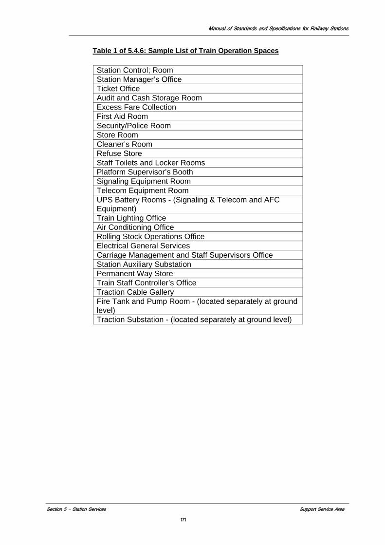
Manual of Standards and Specifications for Railway Stations
Section 5 – Station Services Support Service Area 171
Table 1 of 5.4.6: Sample List of Train Operation Spaces
Station Control; Room Station Manager’s Office Ticket Office Audit and Cash Storage Room Excess Fare Collection First Aid Room Security/Police Room Store Room Cleaner’s Room Refuse Store Staff Toilets and Locker Rooms Platform Supervisor’s Booth Signaling Equipment Room Telecom Equipment Room UPS Battery Rooms - (Signaling & Telecom and AFC Equipment) Train Lighting Office Air Conditioning Office Rolling Stock Operations Office Electrical General Services Carriage Management and Staff Supervisors Office Station Auxiliary Substation Permanent Way Store Train Staff Controller’s Office Traction Cable Gallery Fire Tank and Pump Room - (located separately at ground level) Traction Substation - (located separately at ground level)
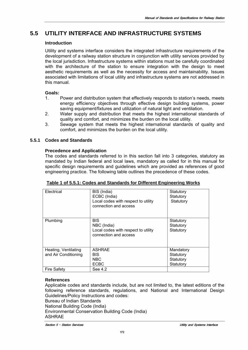
Manual of Standards and Specifications for Railway Station
Section 5 - Station Services Utility and Systems Interface
172
5.5 UTILITY INTERFACE AND INFRASTRUCTURE SYSTEMS Introduction
Utility and systems interface considers the integrated infrastructure requirements of the development of a railway station structure in conjunction with utility services provided by the local jurisdiction. Infrastructure systems within stations must be carefully coordinated with the architecture of the station to ensure integration with the design to meet aesthetic requirements as well as the necessity for access and maintainability. Issues associated with limitations of local utility and infrastructure systems are not addressed in this manual. Goals: 1. Power and distribution system that effectively responds to station’s needs, meets
energy efficiency objectives through effective design building systems, power saving equipment/fixtures and utilization of natural light and ventilation.
2. Water supply and distribution that meets the highest international standards of quality and comfort, and minimizes the burden on the local utility.
3. Sewage system that meets the highest international standards of quality and comfort, and minimizes the burden on the local utility.
5.5.1 Codes and Standards Precedence and Application
The codes and standards referred to in this section fall into 3 categories, statutory as mandated by Indian federal and local laws, mandatory as called for in this manual for specific design requirements and guidelines which are provided as references of good engineering practice. The following table outlines the precedence of these codes.
Table 1 of 5.5.1: Codes and Standards for Different Engineering Works
References Applicable codes and standards include, but are not limited to, the latest editions of the following reference standards, regulations, and National and International Design Guidelines/Policy Instructions and codes: Bureau of Indian Standards National Building Code (India) Environmental Conservation Building Code (India) ASHRAE
Electrical BIS (India) ECBC (India) Local codes with respect to utility connection and access
Statutory Statutory Statutory
Plumbing BIS NBC (India) Local codes with respect to utility connection and access
Statutory Statutory Statutory
Heating, Ventilating and Air Conditioning
ASHRAE BIS NBC ECBC
Mandatory Statutory Statutory Statutory
Fire Safety See 4.2
Manual of Standards and Specifications for Railway Station
Section 5 - Station Services Utility and Systems Interface
173
Indian Railways Works Manual. International Plumbing Guide (USA) Also see Section 4.2 for fire and life safety requirements
5.5.2 Goal and Objectives
The goal of the utility design of a world-class station is to ensure the quality of the station experience to the passenger reflects the highest standards for public transportation facilities. The infrastructure should be designed to support the station operation without interruptions, seamless interconnectivity between systems and the general sense for the passenger that the station infrastructure is an invisible unobtrusive but highly efficient element in the station environment. Objectives Include:
1. Power, Electrical distribution, and Communications
a) Redundancy and flexibility b) Efficiency and sustainability c) Clarity and dependability of communications d) Maintainability and complete accessibility to all systems e) Safety and indefinite emergency capabilities.
2. Plumbing a) Drinking water available to station users to be highest quality potable
water. b) Sustainability through water saving technology and harvesting of
rainwater for reuse. c) Minimize discharge into local sewage system by installation of sewage
treatment plant for reuse of treated water. 3. Heating, Ventilation and Air Conditioning
a) Maximize use of natural ventilation. b) Comfortable and consistent environmental conditions everywhere on the
station complex. c) Maximize flexibility and efficiency through design of system that facilitates
provision of multiple localized environmental systems.
5.5.3 Utility Routing
5.5.3.1 Safety and Maintainability
Utility routing in station public areas shall not be accessible by the public but should be easily reached by the maintenance personnel. This may be achieved by creating separate utility passageways with full access or, where full access is not practical, providing removable panels along the utility routes. Under no circumstances will utility routes be exposed. Planning of utility routing shall consider the following: 1. For the utilities run within the track areas, appropriate clearances shall be
provided to allow for a safe working environment during servicing and/or testing in accordance with applicable codes.
2. Access for maintainability shall not impact on normal operation. If utilities must be buried and not accessible, and maintained only upon failure, adequate redundancy shall be built into the design.
3. Equipment shall be arranged to permit removal of any component from the facility without major disassembly of other equipment components.
For safety reasons, covers or gratings shall be provided for all access openings. Zoning and grouping of utilities by function will provide ease and familiarity for servicing, consequently minimizing accidental disruptions to Station operation by unauthorized personnel.
Manual of Standards and Specifications for Railway Station
Section 5 - Station Services Utility and Systems Interface
174
When specifying equipment, the delivery and maintenance of the equipment to its intended location must be considered including stairs, doorways, corridors, entrances, etc. When locating equipment, careful consideration must be given to clearances for train movements as well as for the safety requirements for maintenance personnel. 5.5.3.2 Integration with Architecture
Utilities in public areas shall be architecturally integrated, meeting aesthetic requirements as well as the necessity including entrances for access and maintainability. Methods for integrating both utility and architectural items shall be considered, by use of the following: 1. Liners and screens 2. Enclosure and separation of routing and utility passageways at the platform,
mezzanine and entrance level public circulation areas 3. Removable panels In nonpublic areas, vertical utility runs should be combined with vertical architectural elements, wherever possible. Utility routing in public areas shall take into consideration signage, information systems, and lighting and acoustic strategies. Use of interchangeable components and modular design should be maximized. Some utilities, such as environmental control system (ECS) ductwork, may require special consideration due to their size and these may need to be run exposed. They shall be fully integrated architecturally, with the station environment.
5.5.3.3 Flexibility and Efficiency
Utility routing shall allow for future system expansion and upgrading, spare capacity for all electrical, communications and signaling systems. 1. Easy, simple and direct passage of utilities 2. Zoning of utility distribution elements and access spaces shall be considered.
5.5.3.4 Sustainable Design
Sustainable development is one of the major goals of Indian Railways. General requirements on applying the concepts of sustainable development to the station design are given in Section 5.2, and detailed later in this section. 5.5.3.5 Integration of Utilities
Integrate utility rooms and runs with overall design to minimize use of materials and facilitate maintenance and service.
5.5.3.6 Station Systems Monitoring – Utilities
Provide computerized station systems monitoring for utility system and integrate with fire safety system monitoring to help ensure timely maintenance of all systems including life safety systems.
5.5.3.7 Routing concepts
Routing in ancillary areas shall allow for the following: 1. Secure and efficient routing that promotes ease of access and maintenance 2. No encroachment into the rolling stock dynamic envelope and minimal disruption
of service for maintenance 3. Clear, direct and unobstructed access by firefighting equipment and personnel
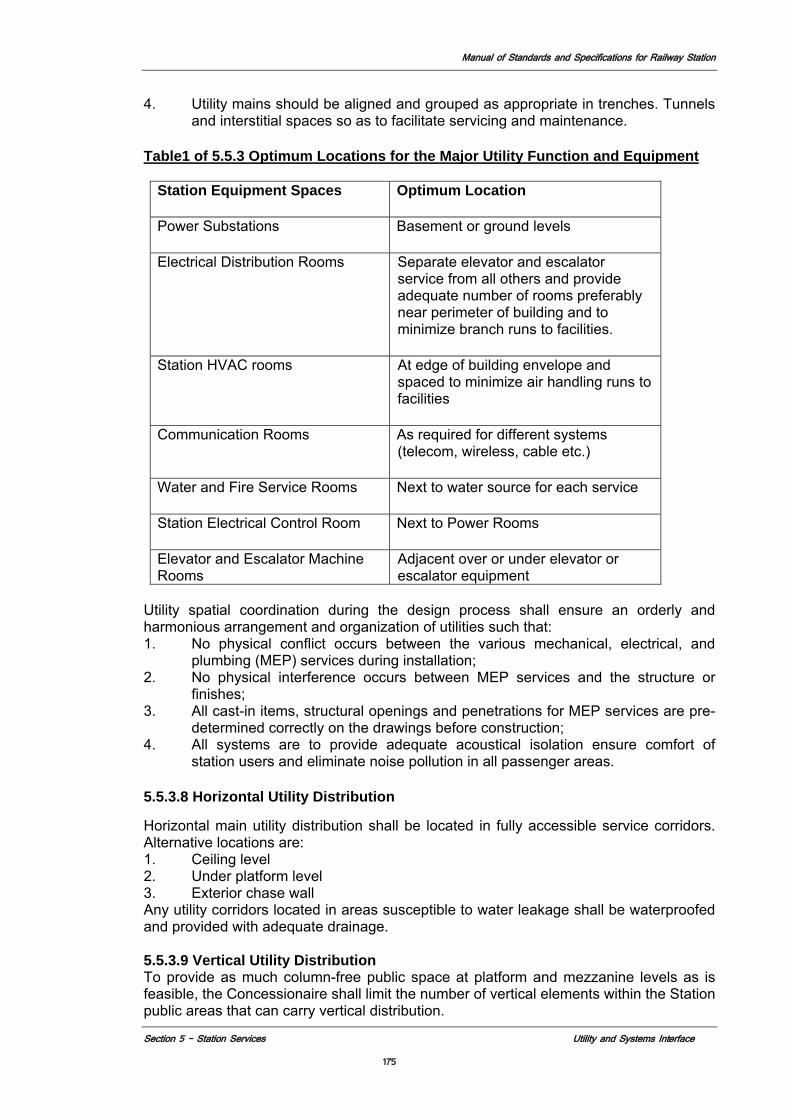
Manual of Standards and Specifications for Railway Station
Section 5 - Station Services Utility and Systems Interface
175
4. Utility mains should be aligned and grouped as appropriate in trenches. Tunnels and interstitial spaces so as to facilitate servicing and maintenance.
Table1 of 5.5.3 Optimum Locations for the Major Utility Function and Equipment
Station Equipment Spaces Optimum Location
Power Substations Basement or ground levels
Electrical Distribution Rooms Separate elevator and escalator service from all others and provide adequate number of rooms preferably near perimeter of building and to minimize branch runs to facilities.
Station HVAC rooms At edge of building envelope and spaced to minimize air handling runs to facilities
Communication Rooms As required for different systems (telecom, wireless, cable etc.)
Water and Fire Service Rooms Next to water source for each service
Station Electrical Control Room Next to Power Rooms
Elevator and Escalator Machine Rooms
Adjacent over or under elevator or escalator equipment
Utility spatial coordination during the design process shall ensure an orderly and harmonious arrangement and organization of utilities such that: 1. No physical conflict occurs between the various mechanical, electrical, and
plumbing (MEP) services during installation; 2. No physical interference occurs between MEP services and the structure or
finishes; 3. All cast-in items, structural openings and penetrations for MEP services are pre-
determined correctly on the drawings before construction; 4. All systems are to provide adequate acoustical isolation ensure comfort of
station users and eliminate noise pollution in all passenger areas.
5.5.3.8 Horizontal Utility Distribution
Horizontal main utility distribution shall be located in fully accessible service corridors. Alternative locations are: 1. Ceiling level 2. Under platform level 3. Exterior chase wall Any utility corridors located in areas susceptible to water leakage shall be waterproofed and provided with adequate drainage.
5.5.3.9 Vertical Utility Distribution To provide as much column-free public space at platform and mezzanine levels as is feasible, the Concessionaire shall limit the number of vertical elements within the Station public areas that can carry vertical distribution.
Manual of Standards and Specifications for Railway Station
Section 5 - Station Services Utility and Systems Interface
176
Vertical routing should be concentrated at the ends of the public areas, within the nonpublic ancillary areas. Other vertical distribution zones may be located discretely throughout the Station as needed.
5.5.4 Utility Adjacency Requirements
Adjacency requirements shall be taken into consideration in utility routing.
5.5.4.1 Electrical Services
In general, "wet" services (e.g., plumbing) shall not be routed through electrical rooms.
5.5.4.2 Low Voltage (LT) System
Lighting conduit distribution will generally be at high level in ancillary spaces. In public areas, conduits shall be positioned to minimize the architectural impact. This may be within an integrated wireway management system, wherein routing for associated systems (including such elements as normal and emergency lighting, signage, closed-circuit television [CCTV], and public address, where feasible) will be incorporated into a wireway system that is part of or directly adjacent to the light fixtures and system components. In all cases, utility routing associated with lighting will be hidden (no exposed conduits) but accessible for maintenance (via access panels or through the lighting system wireway itself).
5.5.4.3 Fire Protection
Wet services shall not be routed through dry services rooms.
5.5.4.4 Fire Standpipe
A fire standpipe system shall be provided for each Station, independent from all other pipe systems including other fire suppression systems (See Section 4.2.4 and 4.2.5).
5.5.4.5 General Plumbing Systems
Storm drainage systems, sanitary sewage system, and other water drainage system should be routes through service areas out of the main passenger spaces and be located convenient to sewage and water treatment facilities and rain water harvesting at the station for reuse for toilet flushing, fire safety, air conditioning and landscaping. Platform drainage water will be collected and discharged to sewage treatment facility.
5.5.4.6 Systems Cable Containment
Power, signaling and communications cable must be carried in separate systems so no induction takes place. In addition all trays or ducts should carry spare capacity for approximately 50%. 1. Signaling
Signal cables run from equipment rooms at stations with track switches to equipment along the track, primarily at crossover locations. Signal cables can be routed through galvanized steel conduits or installed in a cable tray system. If large cable trays are used, then they must have several accessible chambers to facilitate replacement of a cable without disturbing other cables. Signal cabling ducts/trays shall not be more than two layers. Separate provisions shall be made for carrying tail cable to all signaling equipment along the track.
Manual of Standards and Specifications for Railway Station
Section 5 - Station Services Utility and Systems Interface
177
2. Communications
Conduits or cable trays are required for communications cabling. Communication rooms should be located at nonpublic areas. They should not be positioned near any electromagnetic interference (EMI) generators, such as chiller plants, supply power system, traction power system, and the station power systems. Cabling will be required to support the following: a) Voice Communications (including wireless systems) b) Customer-Oriented Systems c) Wi Fi d) Safety and Security Systems e) Cable TV f) Communications Cabling (Transmission Backbone System [TBS])
5.5.5. Electrical
The electrical requirements for a station will be based on the size and configuration of the specific station design. This section outlines the major components and design criteria for the development of a station design. The information provided is to be used as a guide and does not constitute a specification which is contained in the standards and codes referenced and will be developed by the architect for a specific station design.
System shall consist of the following elements: a. Power b. Distribution c. Lifts/Escalators d. Fire detection and Alarm e. CCTV f. Communications 5.5.5.1. Power Power for station will be received at 2 different sources of the local power grid by 2 independent feeders (double circuit) from each. All substations shall be GIS indoor type and shall be provided in the basement or ground floor of the station structure. The power receiving stations are inter-connected for transfer of power from one to another through Fire Retardant Low Smoke (FRLS) cable feeders. These receiving stations should be remote controlled from Centralized Operation Control Centre through Supervisory Control & Data Acquisition System (SCADA). In the event of total power failure station will be automatically switched on and fed the stand by Generator Sets. The station designer will prepare a load analysis for determining the total power requirements. The load analysis should include but are not limited to: Capacity All domestic electrical consumption (fixtures, outlets, switches etc.) All commercial consumption (food service, concessions, etc.) All mechanical equipment (AHU’s, pumps, compressors, etc). All internal and external lighting Miscellaneous (ATMs, TVMs, SIC, telephones, Travel Centre etc.) Coach servicing power requirements as per section 3.3.1
Manual of Standards and Specifications for Railway Station
Section 5 - Station Services Utility and Systems Interface
178
This analysis shall be prepared in conformance with the National Building Code of India and the Bureau of Indian Standards and submitted to MOR and the local jurisdiction for review and approval in order obtain the required power connections. Metering Station metering and sub-metering shall be designed so as to be able to do the following: • Separate station basic operation power consumption from amenities such as
food courts lounges etc. • Distinguish power consumption by mechanical equipment, lighting and other by
major station components and areas. • Monitor all energy efficiency protocols and consumption as required by energy
management plan for the station. 1. Transformers Dry Type Updated and current Indian Standard Specifications and Codes of Practice will apply to the equipment and the work covered by the scope of this contract. In addition the relevant clauses of the Indian Electricity Act, Indian Electricity Rules, National Building Code, National Electric Code, ECBC, Code of Practice for Fire Safety of Building (general): General Principal and Fire Grading–IS 1641 as amended up to date shall also apply. Wherever appropriate Indian Standards are not available, relevant British and/or IEC Standards shall be applicable.
Dry Type Power Transformers IS 11171 – 1985 Fittings and accessories for power transformer IS 3639
Bushing IS 2099 Current transformer IS 2705
The transformer shall be Cast Resin Dry type, naturally air cooled 3 phase, 50 Hz, with a suitable voltage ratio (on no load), solidly earthed system with neutral brought out for independent earthing. Transformer shall be suitable for indoor installation and shall be suitable for continuous operation at rated capacity under site conditions. Insulation class of the transformer shall not be less than class H with temperature rise of 90 deg C over an ambient of 45 deg C. The transformer shall have impedance not exceeding 6.25% and negative tolerance as per IS. The equipment shall be of type tested design at CPRI /Independent test house for short circuit, temperature rise and dielectric tests of the ratings required. All equipments, components, materials and entire work shall be carried out in conformity with applicable and relevant Bureau of Indian Standards and Codes of Practice, as amended upto date. In addition, relevant clauses of the Indian Electricity Act 1910 and Indian Electricity Rules 1956 as amended upto date shall also apply. Wherever appropriate Indian Standards are not available, relevant British and /or IEC Standards shall be applicable. Transformer Characteristics The no load voltage ratio of the transformer shall be 33000/433 volts and the percentage impedance shall not exceed 6.25%. Transformer Terminations The transformer shall have self-supporting cable boxes with suitable glands and cable sockets for receiving 33, 000-volt grade XLPE cables on the H.V. side as required.
Manual of Standards and Specifications for Railway Station
Section 5 - Station Services Utility and Systems Interface
179
The transformers shall be capable of being loaded upto overloads of 15% for one hour, there shall be no limitation imposed by bushings, tap changers etc.
The transformer shall be capable of being operated without danger on any tapping at the rated KVA, with voltage variation of ±10% corresponding to the voltage of the tapping. 2. Generators Diesel Generator Sets suitable for continuous round the clock operation at up to rated output with permissible overload along with associated works. PLC based DG control Panel for Automatic operation of the DG sets is incorporated in the Main L T Panel.
The equipment offered shall conform to the latest revision of relevant Indian or British Standard (BSS.) and Codes together with the requirements of the Local Supply Authority and Department of Explosive etc.
Fuel Consumption The engine shall be suitable for satisfactory operation on HSD/GNG/LNG as locally available. The manufacturers shall declare the guaranteed fuel consumption in liters per liters/hr, in accordance with relevant I.S. or B.S. at 50%, 75% and 100% of rated load at 0.8 pf. Fuel consumption shall be low so as to deliver minimum 4 units per liter at 75% load. Water-cooling system The engine shall be provided with a heat exchanger for closed loop primary cooling water circuit circulated by an engine driven pump for jacket cooling of the engine. The secondary water-cooling circuit of the heat exchanger shall be cooled through a cooling tower by monoblock centrifugal pumps. Soft water (commercial zero hardness) shall be used for initial fill and make up water for secondary cooling circuit and for initial fill of primary cooling circuit. Cooling Tower Cooling tower shall be suitable for outdoor installation. Cooling tower shall be vertical, induced draft, counter/cross flow type in fiber glass reinforcement plastic construction, complete with fan, motor, surface and spray section, eliminators, bird screen and steel supports. The cooling tower capacities shall be compatible with DG sets. Fuel oil system The Bulk Fuel Storage Tanks shall be suitable for storing HSD. The tanks shall conform to IS 10987 -1992 and shall be suitable for underground installation. If GNG is used storage tanks shall conform with all applicable local and national codes and regulations. The tank shall be fabricated from not less than 14 SWG M.S. Sheet. A removable cover of ample size with lock shall be provided to permit access to the tank interior. Fuel level indicator with low and high level visual shall be provided. The day tanks shall be floor/wall supported on steel support 300 mm above FFL.
3. UPS This section covers the requirements of three-phase, on-line, continuous operation, solid-state, Uninterruptible Power Supply (UPS) Systems. The UPS Systems shall operate in conjunction with the existing building electrical system to provide power conditioning, back-up power protection, and power distribution for the critical loads.
Manual of Standards and Specifications for Railway Station
Section 5 - Station Services Utility and Systems Interface
180
Updated and current standards as listed below shall apply to the equipment covered by this contract. In addition the relevant clauses of the Indian Electricity Act 2003 and Indian Electricity Rules 1956 as amended upto date shall also apply.
Safety: • Europe: EN 500091-1 • USA/Canada: UL1778 - Standards for Uninterruptible Power Supply
Equipment. Mode of operation The UPS shall operate as an on-line system in the modes listed below:
a) Normal operation: The inverter/battery charger shall operate in an on-line manner to continuously regulate the power to the critical load. The Inverter/battery charger also shall derive power from the AC Input source and supply DC Power to float-charge the battery.
b) Battery: Upon failure of the AC Input source, the critical load shall
continue to being supplied by the Inverter without any switching. The Inverter shall obtain its power from the battery. There shall be no interruption in power to the critical load upon failure or restoration of the AC Input source.
c) Recharge: Upon restoration of the AC input source, the Inverter/battery
charger shall simultaneously recharge the battery and regulate the power to the critical load.
d) Bypass: The static bypass switch shall be used for transferring the critical
load to mains supply without interruption. Automatic re-transfer to normal operation shall also be accomplished with no interruption in power to the critical load. No re-booting of microprocessor shall take place after transfer and retransfer of critical load.
Environmental requirements:
• Storage ambient temperature: -50 to 700C • Operating ambient temperature: 0 to 300C Continuous operation. • Relative Humidity: 0-95%, non-condensing.
5.5.5.2. Distribution
1. Cabling HT Cables HT cable aluminum conductor with Cross-linked polyethylene (XLPE) insulation galvanized steel armoring and PVC sheathing conforming to IS 7098. LT Cables LT cables shall be aluminum conductor XLPE insulated, PVC sheathed armoured conforming tolls 155417098. Cables shall be rated for an 1100 Volts.
Short circuit rating of cables shall be as specified in IS 1554 Part-I.
Cables have to be selected considering conditions of maximum connected loads, ambient temperature, grouping of cables and allowable voltage drop.
Manual of Standards and Specifications for Railway Station
Section 5 - Station Services Utility and Systems Interface
181
Updated and current Indian Standard Specifications and Codes of Practice as stipulated below shall apply to the equipments and the work covered in this section. In addition the relevant clauses of the Indian Electricity Act 2003, Indian Electricity Rules 1956, National Building Code 1994, National Electric Code 1985, Code of Practice for Fire Safety of Building (general): General Principal and Fire Grading - IS 1641 as amended unto date shall also apply. Wherever appropriate Indian Standards are not available, relevant British and/or IEC Standards shall be applicable. PVC insulated heavy duty cables IS 1554 - 1988 Cross link polyethylene insulated PVC (sheathed XLPE cables) IS 7098 - 1985 Code of practice for installation and maintenance of power cables IS 1255 - 1983 Conductors for insulated electrical cables IS 8130 - 1984 Drums for electrical cable IS10418–1982 Methods of test for cables IS 10810 – 1988 Recommended current rating IS3961–1987 Recommended short circuit rating of high voltage PVC cables IS 5891 – 1970 2. Boards LT Distribution boards Distribution Boards (DBs) suitable for operation .on 415 V 3 Phase 4 wire 50 Hz supply feeding final lighting and power sub circuits. Indian Standard Specifications and Codes of Practice will apply to the equipment and the work covered by the scope of this contract. In addition the relevant clauses of the Indian Electricity Act 1910, Indian Electricity Rules 1956, National Building Code 1997, National Electric Code 1.985, Code of Practice for Fire Safety of Building (general): General Principal and Fire Grading - IS 1641 - 1988 as amended up to date shall also apply. Wherever appropriate Indian Standards are not available, relevant British and/or IEC Standards shall be applicable. LT Switchboards The allowable temperature rise for LT Panels, and all LT switchgears including rising mains and busducts shall be 50 deg C above ambient of 45 deg C. Updated and current Indian Standard Specifications and Codes of Practice will apply to the equipment and the work covered by the scope of this contract. In addition the relevant clauses of the Indian Electricity Act 1910, Indian Electricity Rules 1956, National Building Code 1994, National Electric Code 1985, Code of Practice for Fire Safety of Building (general): General Principal and Fire Grading - IS 1641 - 1988 as amended upto date shall also apply. Wherever appropriate Indian Standards are not available, relevant British and/or lEC Standards shall be applicable. 3. Risers Rising mains & Bus ducts Compact Sandwich Type Aluminum conductor L T Bus Trunking Systems LT (Rising Mains with Tap Off facilities and Bus Ducts) suitable for indoor installation. Updated and current Indian Standard Specifications and Codes of Practice will apply to the equipment and the work covered by the scope of this contract In addition the relevant clauses of the Indian Electricity Act 2003, Indian Electricity Rules 1956, National Building Code 1994, National Electric Code 1985, Code of Practice for Fire Safety of Building (general): General principal and Fire Grading - IS 1641 as amended up to date shall also apply. Wherever appropriate Indian Standards are not available, relevant British and/or IEC Standards shall be applicable.
Manual of Standards and Specifications for Railway Station
Section 5 - Station Services Utility and Systems Interface
182
Busbars Busbar shall be fabricated from IQSOI grade aluminum or 99.9% pure ETP grade copper as applicable. Rating of busbar shall be as specified in drawings / Schedule of quantities. Wiring Internal Wiring Installation in concealed/surface conduit/raceways pertaining to: • Lights and fans • Convenience socket outlets • Control wiring • Sub main wiring Updated and current Indian Standard Specifications and Codes of Practice as stipulated below shall apply to the equipments and the work covered in this section. In addition the relevant clauses of the Indian Electricity Act 1910, Indian Electricity Rules 1956, National Building Code 1994, National Electric Code 1985, Code of Practice for Fire Safety of Building (general): -'General Principal and Fire Gracing - IS 1641 and IEE wiring regulation 16th edition as amended upto date shall also apply. Wherever appropriate Indian Standards are not available, relevant British and/or IEC Standards shall be applicable.
5.5.5.3. Lifts The following Indian Standard Specifications and Codes of Practice, currently applicable and updated as of date irrespective of dates given below, shall apply to the equipments and the work covered by this contract. In addition the relevant clauses of the Indian Electricity Act 1910 and Indian Electricity Rules 1956 as amended upto date shall also apply. Wherever appropriate Indian Standards are not available, relevant British and/or IEC Standards shall be applicable. Electric Traction Lifts - Guideline for outline dimension IS 14665 (Part-I) - 2000 Electric Traction Lifts - Code of practice for installation IS 14665 (Part-2) - 2000 Electric Traction Lifts - Safety Rules IS 14665 (Part-3) - 2000 Electric Traction Lifts – Components IS 14665 (Part-4) - 2000 Electric Traction Lifts - Inspection manual IS 14665 (Part-5) - 2000 1 Electric supply The available system of electric supply is 415 volts + 1 0% -20% between phases and 240 volts between phase and neutral - 3 phase 4 wire AC 50 Hz system. In addition, for illumination and control, power at 240 volts AC single phase 50 Hz shall also be available. Any equipment /component operating at other than the above mentioned power supply shall be provided with necessary transformers/voltage stabilizers. The amount of power required for lifts shall be indicated in the tender. Power shall be provided at one point in each Machine Room. Electricity connection required for every train line serviced by a platform at the station. Line shall be capable to electricity supply of 24 coach trains. Every coach has two easy connection coupling. 2. Control system The Lifts shall have state of art microprocessor based AC variable voltage variable frequency (ACVVVF) drive. Single lifts shall be provided with directional collective control for one car (also called Simplex Full Collective Control). Two lifts adjacent to each other in one location shall be provided with Directional Collective Control for two cars with Group Supervisory Control. The control system shall regulate dispatching of
Manual of Standards and Specifications for Railway Station
Section 5 - Station Services Utility and Systems Interface
183
individual cars and shall provide service to all floors as different traffic conditions arise minimizing unproductive factors. The system shall respond automatically to UP and DOWN peak, balanced or light traffic etc. Some of the technical parameters required are innumerate below.
a) Starting current 1.2 - 1.5 times full load running current b) Power saving 50 - 55% c) Leveling accuracy+5 mm d) Acceptable voltage fluctuation+10 to -20% e) Rate of acceleration/deceleration (M/S2) 0.6 - 1.5 (Adjustable at site) f) Maximum jerk (M/S3) 0.7 - 1.5 (Adjustable at site) g) Maximum vibration in car horizontal! Vertical 20/18 dBA h) Maximum noise level in car during travel 48 dBA i) Maximum noise level in machine room at I mtr from machine 62 dBA j) Maximum door noise level while closing and opening at a distance of I
mtr from car door 52 dBA Battery operated Automatic Rescue Device (ARD) shall be provided for each lift which shall allow the lift car to release to next floor landing with lift door open and shut down for operation. The ARD shall be operated automatically in case of any power failure to the lift installation for more than a preset time (0-10 minutes). 3. Cabling Cabling between switchboard and the controller /lift motor shall be with XLPE insulated HR PVC sheathed 1100 volt grade aluminum conductor armoured cables conforming to IS 7098 or PVC insulated, PVC sheathed, 1100 volt grade al conductor armoured cables conforming to IS 1554. Wiring All wiring shall be carried out with FRLS PVC insulated 1100 volt grade stranded copper conductor wires conforming to IS 694 drawn in MS rigid / flexible conduit system and / or MS raceways. Minimum 2.5 sq mm size wires shall be used. Earthing Metal enclosures of all electrical equipment and devices including frames of motors, controllers, switchgear, conduits and raceways etc. shall be properly earthed so as to form an equvi-potential zone.
5.5.5.4. Escalators The escalator system shall be complete with all standard accessories and fittings like tracks, truss, drive with controls, balustrade, handrail, steps, chain-driving mechanism etc. The following BIS Standards and Codes of Practice with upto date amendments shall apply to the equipment and the work. Code of practice for installation and maintenance of escalators IS 4591: 1968 Safety rules for the construction and installation of escalators DIN EN 115: 1995 and passenger conveyors Code of practice for electrical wiring installations IS 732-1963 (system voltage not exceeding 650 volts)
Manual of Standards and Specifications for Railway Station
Section 5 - Station Services Utility and Systems Interface
184
The drive unit shall be located at the upper end of the escalator and shall consist of a heavy duty compact gear. Effective means shall be provided for automatic and continuous (life time) lubrication of the entire mechanism. The drive motor shall be 3 phases, 415 volts, 50 CIS. The motor shall be able to operate satisfactorily between 390 V and 440 V.
5.5.5.5. Fire Detection and Fire Alarm The fire alarm system shall comply with requirements of NFPA Standard No. 72 for protected premises signaling systems except as modified and supplemented by this specification. The system shall be supervised either electrically or by software-directed polling of field devices. The facility shall have an emergency voice alarm communication system. The digitized recorded voice message shall notify occupants that a fire condition has been reported. The message shall instruct the occupants with emergency instructions. Emergency manual voice override shall be provided. Each designated zone shall transmit separate and different alarm, supervisory and trouble signals to the Fire Command Center (FCC) and designated personnel in other buildings at the site via a multiplex communication network. The system shall be an active/interrogative type system where each transponder and/or addressable device is repetitively scanned, causing a signal to be transmitted to the main fire alarm control panel (FACP) indicating that the device and its associated circuit wiring is functional. Loss of this signal at the main F ACP shall result in a trouble indication as specified hereinafter for the particular input. A.C. Power Supply Fault and Fire indication lamp. Alarm acknowledgment push buttons. The circuits provided the control panel for each zone shall indicate the following conditions: i. Open Circuit in zone wiring ii. Short Circuit in zone wiring iii. Normal conditions iv. Power failure v. Low battery. The Automatic annunciation panel shall suitable for operation on 24 V DC and shall be provided with power supply unit suitable to operate on A.C. mains of 230V with a variation of 10%. The system shall be so designed that in case of failure of A.C. main supply it shall automatically change over to battery supply.
1. Basic Performance Alarm and trouble signals from each transponder shall be digitally encoded by listed electronic devices onto an NFPA Style 7 looped multiplex communication system. Alarm, trouble and supervisory signals from all intelligent reporting devices shall be encoded onto NFPA Style 7 Signaling Line Circuits. Digitized electronic signals shall employ check digits or multiple polling. Transponder devices are to consist of low current, solid-state integrated circuits, and shall be powered from local a primary power and standby battery power source.
Manual of Standards and Specifications for Railway Station
Section 5 - Station Services Utility and Systems Interface
185
Power for initiating devices and notification appliances must be from the main fire alarm control panel or the transponder to which they are connected. A single ground or open on any system signaling line circuit, initiating device circuit, or notification appliance circuit shall not cause system malfunction, loss of operating power or the ability to report an alarm. Alarm signals arriving at the main FACP shall not be lost following a power failure (or outage) under any circumstances. Hooter/strobe circuits shall be arranged such that there is a minimum of one Hooter/ strobe circuit per smoke zone. Hooter circuits shall be electrically supervised for open and short circuit conditions. If a short circuit exists on a hooter circuit, it shall not be possible to activate that circuit. Audio amplifiers and tone generating equipment shall be electrically supervised for abnormal conditions. Amplifiers shall be located in transponder cabinets to simplify installation and to reduce power losses in wiring. Hooter circuits shall be 25 VRMS. Hooter circuits shall have 30% spare capacity for future expansion or increased power output requirements. Hooter circuits and control equipment shall be arranged such that loss of anyone (1) speaker circuit will not cause the loss of any other speaker circuit in the system. Two-way telephone communication circuits shall be arranged so as to allow communication between the fire command center and up to seven (7) remote telephone locations simultaneously. Means shall be provided to connect the telephone circuits to the P.A. System circuits to allow voice communication over the PA System circuit from a telephone handset. A prerecorded voice module shall be used to store tones and/or messages and transmit them over P.A System circuits automatically upon alarm actuation. The voice module shall be reliable, non-moving parts. System Functional operation When a fire alarm condition is detected and reported by one of the system initiating devices or appliances, the following functions shall immediately occur: The System Alarm LED shall flash. A local piezo-electric signal in the control panel shall sound. The SO-character LCD display shall indicate all information associated with the fire alarm condition, including the type of alarm point and its location within the protected premises. Printing and history storage equipment shall log the information associated with the fire alarm control panel condition, along with the time and date of occurrence. All system output programs assigned via control-by-event equations to be activated by the particular point in alarm shall be executed, and the associated system outputs (alarm notification appliances and/or relays) shall be activated.
Manual of Standards and Specifications for Railway Station
Section 5 - Station Services Utility and Systems Interface
186
The audio portion of the system shall sound the proper signal (tone or voice) to the appropriate zones. The system shall activate the digitized recorded voice message through the PA system, which shall notify occupants that a fire condition has occurred. Installation shall be in accordance with the NEC, NFPA 72 and Indian National/local codes. All Equipment shall be attached to walls and ceiling/floor assemblies and shall be held firmly in place (e.g., detectors shall not be supported solely by suspended ceilings). Fasteners and supports shall be adequate to support the required load Initiating circuits shall be arranged to serve like categories (manual, smoke, water flow). Mixed category circuitry shall not be permitted except on signaling line circuits connected to intelligent reporting devices. The main fire alarm control panel shall be connected to a separate dedicated branch circuit, maximum 20 amperes. This circuit shall be labeled at the main power distribution Panel as FIRE ALARM. Fire alarm control panel primary power wiring shall be 4.0 SQ. mm FRLS PVC insulated copper wires. The control panel cabinet shall be grounded securely to the system earthing. 2. Batteries and External Charger Battery shall have sufficient capacity to power the fire alarm system for not less than twenty-four hours plus 5 minutes of alarm upon a normal AC power failure. External Battery Charger: Shall be completely automatic, with constant potential charger maintaining the battery fully charged under all service conditions. Charger shall operate from a 240-volt 50-hertz source. Shall be rated for fully charging a completely discharged battery within 48 hours while simultaneously supplying any loads connected to the battery. Shall have protection to prevent discharge through the charger. Shall have protection for overloads and short circuits on both AC and DC sides. 3. Typical Operation Actuation of any manual station, smoke detector, heat detector or water flow switch shall cause the following operations to occur unless otherwise specified: Activate all programmed sounder circuits. Actuate strobe units until the panel is reset. Light the associated indicators corresponding to active sounder circuits. Release all magnetic door holders to doors to adjacent zones on the floor from which the alarm was initiated. Duct type smoke detectors shall, in addition to the above functions, shut down the ventilation system or close associated control dampers as appropriate.
Manual of Standards and Specifications for Railway Station
Section 5 - Station Services Utility and Systems Interface
187
HVAC/Smoke Control System Operation: On/Auto/Off switches and status indicators (LEDS) shall be provided for monitoring and manual control of each fan, damper, HV AC control unit, stairwell pressurization fan, and smoke exhaust fan. The OFF LED shall be Yellow, the ON LED shall be green, and the Trouble/Fault LED shall be Amber/Orange for each switch. The Trouble/Fault indicator shall indicate a trouble in the control and/or monitor points associated with that switch. In addition, each group of eight switches shall have two LEDS and one momentary switch which allow the following functions: An Amber LED to indicate an OFF-NORMAL switch position, in the ON or OFF. Each switch shall have the capability to monitor and control two addressable inputs and two addressable outputs. In all modes, the ON and OFF indicators shall continuously follow the device status not the switch position. Positive feedback shall be employed to verify correct operation of the device being controlled. Systems that indicate on/off/auto by physical switch position only are not acceptable. All HV AC switches (i.e., limit switches, vane switches, etc.) shall be provided and installed by the HV AC contractor. It shall be possible to meet the requirements mentioned above utilizing wall mounted custom graphic annunciators if the project requires such.
5.5.5.6. CCTV
The digital video recording, management and transmission system shall be designed to meet the requirements of surveillance as required at the Station Centre. The system shall offer network connectivity to other family components and provide all video and control data over the Ethernet network to other recorders and workstations. The number of network-connected components is only limited to the number of assigned IP addresses. The system shall offer multiple continuously recorded digital video channels onto a hard drive medium. The system shall employ software run on a Microsoft@ Windows XP Embedded@ platform. The software shall employ an optimized-MPEG4 compression algorithm in the video digitizing scheme. The networked system shall comprise of recorders and workstations. The recorder, without any degradation to frame rates or resolution, shall simultaneously offer:
1. 16-channel video recording. 2. 16-channel video playback. 3. 16-channel video transmission to the Ethernet network. 4. User selectable video archiving of pre-existing recording.
The Function Control Area shall provide a palette of controls to enable or disable the video recording as well as any currently running macros in the system. Alarm processing shall include but not be limited to:
1. External Alarms. 2. Sensor Alarm that shall have the ability to be tagged as follows:
a. Intrusion Alarms. b. Motion Detector Alarms. c. Smoke Detector Alarms. d. Perimeter Detector Alarms.
e. Fire Alarms. 3. Other types of detector alarms. 4. Camera alarms shall include but not be limited to:
Manual of Standards and Specifications for Railway Station
Section 5 - Station Services Utility and Systems Interface
188
a. Video Motion Alarms, based on an "Area of Interest" utility. b. Video Loss Alarms. 5. An authorized user shall link alarm conditions to preprogrammed macros to
further extend the usability of the system. 6. Alarm scheduling shall include but not be limited to distinct activity items, each
including: a. Beginning and end time for when each alarm is active. b. Day of the week for when an alarm is active. 5.5.5.7 Communications Infrastructure shall be provided for the following station communications systems: a. PA system (see section 4.11.6.7.) b. Centralized train information system c. Telephone system for concessionaire station operation, MOR operation,
concessions and amenities d. Computer internet access (WiFi) e. Mobile phone use within the station structure Cabling and distribution requirements for systems a to c are defined earlier in this section. Following are requirements of the wireless systems 1. WIFI System/Mobile Phone Performance A digital communication system is measured in bit/s/Hz [1], or less frequently but unambiguously (bit/s)/Hz. It is the net bit rate or maximum throughput divided by the bandwidth in hertz of a communication channel or a data link. Spectral efficiency is typically used to analyze the efficiency of a digital modulation method, sometimes in combination with a forward error correction (FEC) code and other physical layer overhead. In the latter case, a "bit" refers to a user data bit; FEC overhead is always excluded. Simple example: A transmission technique using one kilohertz of bandwidth to transmit 1000 bits per second has a spectral efficiency of 1 (bit/s)/Hz. Telephone modem example: A V.92 modem for the telephone network can transfer 56,000 bit/s downstream and 48,000 bit/s upstream over an analog telephone network. Due to filtering in the telephone exchange, the frequency range is limited to between 300 hertz and 3,400 hertz, corresponding to a bandwidth of 3400 − 300 = 3100 hertz. The spectral efficiency is 56,000/3,100 = 18.1 (bit/s)/Hz downstream, and 48,000/3,100 = 15.5 (bit/s)/Hz upstream. Numerical example: A 8PSK modem has an alphabet size of M=8 alternative symbols, with N=3 bits/symbol, resulting in that the spectral efficiency cannot exceed 2N = 6 (bit/s)/Hz in the base band case, and N = 3 (bit/s)/Hz in the pass band case. Hardware An embedded Router Board 112 with U.FL-RSMA pigtail and R52 mini PCI Wi-Fi card widely used by wireless Internet service providers (WISPs). A wireless access point connects a group of wireless devices to an adjacent wired LAN. An access point is similar to a network hub, relaying data between connected wireless devices in addition to a (usually) single connected wired device, most often an Ethernet hub or switch, allowing wireless devices to communicate with other wired devices.
Manual of Standards and Specifications for Railway Station
Section 5 - Station Services Utility and Systems Interface
189
Wireless adapters allow devices to connect to a wireless network. These adapters connect to devices using various external or internal interconnects such as PCI, miniPCI, USB, Express Card, Card bus and PC card. Most newer laptop computers are equipped with internal adapters. Internal cards are generally more difficult to install. Wireless routers integrate a WAP, Ethernet switch, and internal Router firmware application that provide IP Routing, NAT, and DNS forwarding through an integrated WAN interface. A wireless router allows wired and wireless Ethernet LAN devices to connect to a (usually) single WAN device such as cable modem or DSL modem. A wireless router allows all three devices (mainly the access point and router) to be configured through one central utility. This utility is most usually an integrated web server which serves web pages to wired and wireless LAN clients and often optionally to WAN clients. This utility may also be an application that is run on a desktop computer such as AirPort. Wireless range extenders or wireless repeaters can extend the range of an existing wireless network. Range extenders can be strategically placed to elongate a signal area or allow for the signal area to reach around barriers such as those created in L-shaped corridors. Wireless devices connected through repeaters will suffer from an increased latency for each hop. Additionally, a wireless device connected to any of the repeaters in the chain will have a throughput that is limited by the weakest link between the two nodes in the chain from which the connection originates to where the connection ends.
5.5.6. Plumbing and Fire Fighting
The plumbing requirements for a station will be based on the size and configuration of the specific station design. This section outlines the major components and design criteria for the development of a station design. The information provided is to be used as a guide and does not constitute a specification which is contained in the standards and codes referenced and will be developed by the architect for a specific station design. System shall consist of the following elements: a. b. Sanitary fixtures. c. Soil, Waste, Rainwater and Vent pipes. d. Water Supply (Internal & External) including cold and hot water supply. e. External Sewage System. f. Storm Water Drainage System. g. Sewage treatment plant h. Water treatment plant i. Tube well, Irrigation (horticultural) and water body systems. j. Coach watering system on platforms. k. Sprinkler System l. Standpipe System m. Water storage capacity for fire fighting
5.5.6.1. Water Supply Water Supply to meet the stations needs shall come from three sources • City supply to meet demand for potable water and additional demands not met
by other two sources. The provision of tube well water treated for domestic
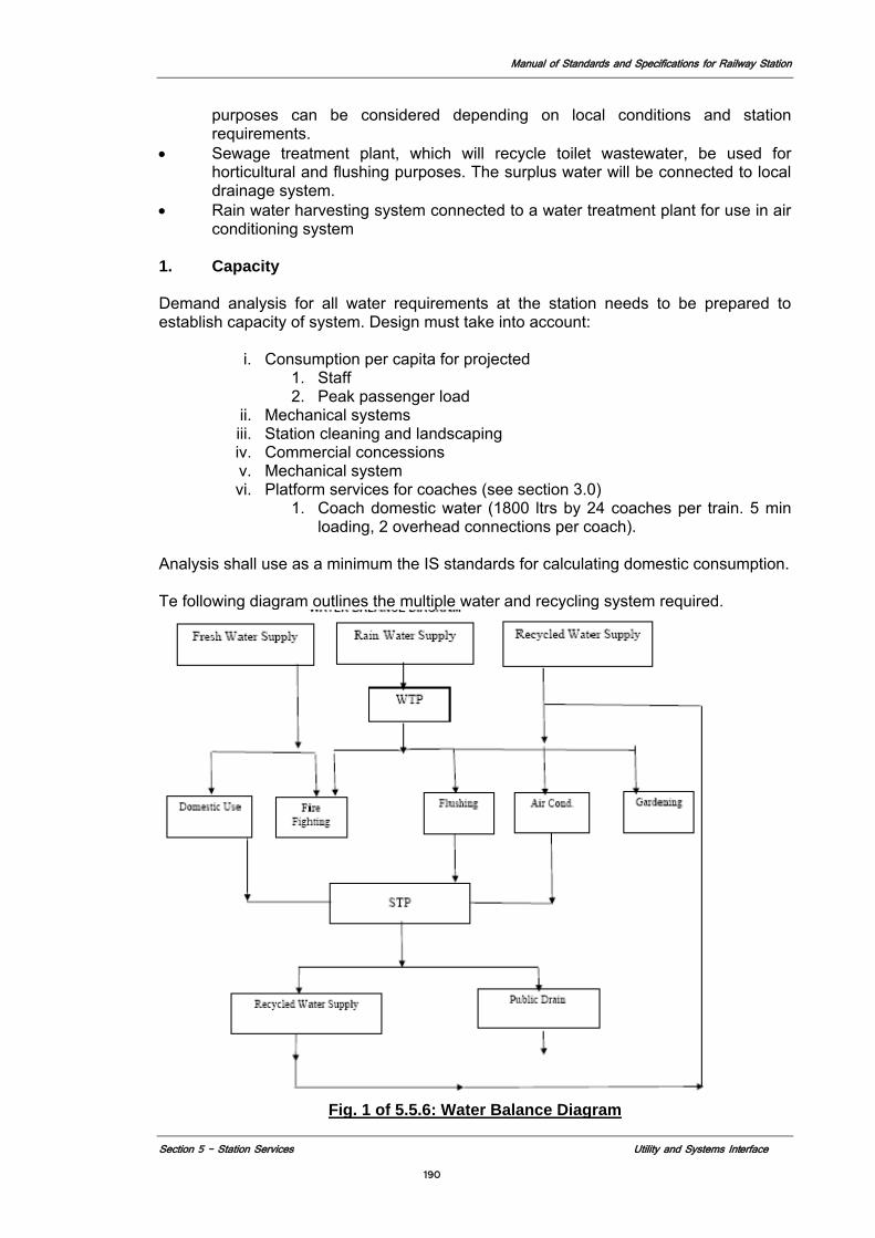
Manual of Standards and Specifications for Railway Station
Section 5 - Station Services Utility and Systems Interface
190
purposes can be considered depending on local conditions and station requirements.
• Sewage treatment plant, which will recycle toilet wastewater, be used for horticultural and flushing purposes. The surplus water will be connected to local drainage system.
• Rain water harvesting system connected to a water treatment plant for use in air conditioning system
1. Capacity
Demand analysis for all water requirements at the station needs to be prepared to establish capacity of system. Design must take into account:
i. Consumption per capita for projected 1. Staff 2. Peak passenger load
ii. Mechanical systems iii. Station cleaning and landscaping iv. Commercial concessions v. Mechanical system vi. Platform services for coaches (see section 3.0)
1. Coach domestic water (1800 ltrs by 24 coaches per train. 5 min loading, 2 overhead connections per coach).
Analysis shall use as a minimum the IS standards for calculating domestic consumption. Te following diagram outlines the multiple water and recycling system required.
Fig. 1 of 5.5.6: Water Balance Diagram
Manual of Standards and Specifications for Railway Station
Section 5 - Station Services Utility and Systems Interface
191
2. Pumping System Jockey Pumps Pumping Sets Pumping sets shall be single/multi stage horizontal centrifugal single outlet with stainless steel/cast iron body and bronze dynamically balanced impellers. Connecting shaft shall be stainless steel with bronze sleeve and grease-lubricated bearings. The pump shall meet the requirements of the Local Fire Department and the unit shall be design proven in fire protection services. Electric Drive Electrically driven pumps shall be provided with totally enclosed fan cooled induction motors. For fire pumps the motors should be rated not to draw starting current more than 3 times normal running current. Motors for fire protection pumps shall be at least equivalent to the horse power required to drive the pump at 150% of its rated discharge and shall be designed for continuous full load duty and shall be design proven in similar service. Motors shall be wound for class B insulation and winding shall be vacuum impregnated with heat and moisture resistant varnish glass fibre insulated, and suitable for 415 volts, 3 phase 50 cycles ale supply and shall be designed for 38 deg. C ambient temperature. Motors shall conform to LS. 325. Motors shall be designed for two-start system. Air Vessel Provide one air vessel fabricated from 10 mm M.S. plate with dished ends and suitable supporting legs with flanged connection from pump. The fire pumps shall operate on drop of pressure in the mains as given below. The pump operating sequence shall be arranged in a manner to start the pump automatically but should be stopped manually by starter push buttons only. Vibration Eliminators Provide on all suction and delivery lines double-flanged reinforced neoprene flexible pipe connectors. Connectors should be suitable for a working pressure of each pump and tested to the test pressure given in the relevant head. Water Heaters Water Heaters shall be automatic pressure type water heater with pressure release valve, non-return valve and inlet and outlet stop valves as required. Water heaters to conform to IS: 2082 Electric Drive Electrically driven pumps shall be provided with totally enclosed fan cooled induction motors. For fire pumps the motors should be rated not to draw starting current more than 3 times normal running current. Motors for fire protection pumps shall be at least equivalent to the horse power required to drive the pump at 150% of its rated discharge and shall be designed for continuous full load duty and shall be design proven in similar service.
Manual of Standards and Specifications for Railway Station
Section 5 - Station Services Utility and Systems Interface
192
Motors shall be wound for class B insulation and winding shall be vacuum impregnated with heat and moisture resistant varnish glass fibre insulated. Motors for fire pumps shall meet all requirements and specifications of the Tariff Advisory Committee. Motors shall be suitable for 415 volts, 3 phase 50 cycles ale supply and shall be designed for 38 deg. C ambient temperature. Motors shall conform to LS. 325. Motors shall be designed for two-start system. Motors shall be capable of handling the required starting torque of the pumps. Contractor shall provide inbuilt heating arrangements for the motors for main pumps to ensure that motor windings shall remain dry. Speed of the motors shall be compatible with the speed of the pump. 3. Power Control Panels
Construction General Features: - The power and control panel shall be totally enclosed dust and vermin proof free standing floor mounted cubicle type, fabricated out of sheet steel not less than 2mm thick. General construction shall be of compartmentalization and sectionalised such as mains incomer, electric fire pump, diesel fire pump, pressurization pump, priming pump and control, so that there is no mix up of power and control wiring and connections in the same sections as far as possible. The panel shall be front operated type with all connections accessible from the front. Front doors shall be hinged type. The construction shall be to IP 21 as per IS: 2147. Cable entries and gland plates AH cable entries shall be through double compression plates, which are removable, and stationalised. Necessary compression type glands shall also be provided. Busbar and connections The bus bars shall be air insulated and of aluminum of high conductivity electrolytic quality (grade E91E to IS 5082) and of adequate cross section. Earthing Arrangement GI strip 25mm x 5mm shall be run at the rear of the board, bonding all the sections suitably. 2 nos. earth terminals shall be provided at the ends of the GI strip for connection to earth system. Terminal Blocks "and Small Wiring Terminal blocks shall be of heavy-duty type and generally not less than 15Amps 250V grade upto lOOV, and 600V grade for the rent of the functions. They shall be easily accessible for maintenance. All control wiring inside the panel shall be with PVC insulated copper conductor of 2.5 sq.mm size and 600 V grade conforming to IS: 694-1977. 4. Rainwater Harvesting System
The system shall take in to account: Total Plot Area, Built up area at ground level & Green area. Run off co-efficient of various surface Tables.
Manual of Standards and Specifications for Railway Station
Section 5 - Station Services Utility and Systems Interface
193
Roof Tiles, Lawns, Green area and Hard/Paved Built up area. All internal drain to be design on 1 cusec per acre Use National Building Code for Rain Harvesting and conservation Table the annual for calculating rainfall in Locality. Design on the basis of IS Norms. Example
Suppose Rainfall intensity : 63mm / hour occurring one in 2 years. Time of duration : 30 minutes. Average run off co-efficient : 0.60 Total run off : 11.54 x 28.31 = 326.70 LPS. Considering 5 – 10 minute storage in Harvesting Wells: 10x60x326.70 = 196020 Litres or 196.02 M3 Harvesting Well proposed 5 x 42 M3 = 210 M3
5. Water Treatment
Water Filter Filter shall be designed in accordance with the code of unfired pressure vessel conforming to IS: 2825. Example: sand / gravel pressure filters downward or upward flow type suitable for a rate of filtration given in Schedule of Quantities. Filter shall be vertical type of required diameter. The shell and dished ends shall be fabricated from M.S. plates conforming to IS: 2002 Gr. The minimum thickness of shell shall be 6mm and dished ends shall be 8mm. The filter shall have at least one pressure tight manhole cover. Air Blower Air blower shall be rotary type for scouring filter and assisting in back was operation. Air blower shall be driven by a totally enclosed fan cooled induction motor of required H.P. Blower shall be of capacity recommended by filter manufacturer. Chemical Dosers Chemical dosers shall be displacement type complete capacity as. Doser shall be suitable for working pressure and shall be provided with orifice plate assembly, injection nozzle and corrosion proof piping. Piping from main water supply line to the doser shall be G.I. pipes conforming to IS: 1239 (Medium class) Water Softener Softener shall be designed in accordance with the code of unfired pressure vessel conforming to IS: 2825. Softener shall be designed to give zero commercial hardness. Softener shall be with "Cation" exchange resins. Softener vessel shall be mild steel or FRP and self-supporting arrangement. Vessel shall be suitable for a working pressure. The materials of both shell and dish ends shall conform to IS: 2002.
5.5.6.2. Distribution A water supply piping system to cater for all domestic requirements shall consist of galvanized steel pipes and fittings for water mains. As far as possible all piping inside the building shall run in shaft or ducts provided for this purpose. Outside the buildings, the piping shall be installed as far as possible 60cm below finished grade. Where called for all galvanized steel piping embedded either in the trenches or in concrete and masonry work shall be rightly wrapped with 1mm thick fiberglass tissue sheeting laid in
Manual of Standards and Specifications for Railway Station
Section 5 - Station Services Utility and Systems Interface
194
bitumen after testing the pipe. Gate valves (built into chambers where required) shall be provided. Cold Water Supply Pipe Concealed cold water pipes and fittings after hydraulic test will have two coat of bitumen paint, two layers of heavy gauge polyethylene sheet. Exposed cold water supply after hydraulic test will be painted with two or more coats of enamel paint of approved shade over a coat of primer. Water Meters Water meters shall conform to IS: 779-1968 or IS: 2373-1968 Rain Water Pipes Rain water down take shall be galvanized mild steel pipes or cast iron pipes as called for in the drawings. The fittings and specials for the pipes shall be of the same materials as that of pipes. Cement Concrete Pipes They shall conform to IS: 458-1971. The reinforced concrete pipes shall be manufactured by centrifugal (or spun) process while un-reinforced cement concrete pipes by spun or pressure process. Galvanized Iron Pipes and Fittings The pipes shall be galvanized mild steel medium heavy, as specified, conforming to IS: 1239-1973 Part I & II. UPVC pipes and fittings Where specified, UPVC pipes for drainage system shall be rigid UPVC pipes of class 6/10 kg/cm2 as specified, conforming to IS: 4984-1983. Copper Pipes and Fittings All cold and hot water pipes within the building and upto the water main outside shall be copper tubing conforming to BS 2871, Part-I table X. The fittings shall be capillary type to BS 864 with silver brazing rings. Stone Ware Pipes The laying and jointing of stoneware pipes shall be executed in accordance with code of practice for laying of glazed stoneware pipes IS: 4127-1967. Cement Concrete Pipes Concrete pipes shall be laid and jointed as described in IS: 783/1959 Code of practice for laying of cement concrete pipes. Cast Iron Pipes Cast iron pipes shall be laid and jointed in conformity with the code of practice for laying of cast iron pipes IS: 3114-1960. Sewerage and Drainage Pipes (S. W and R.C.C. Pipes) All lengths of sewer and drain lines shall be fully tested for water tightness by means of water pressure maintained for not less than 30 minutes.
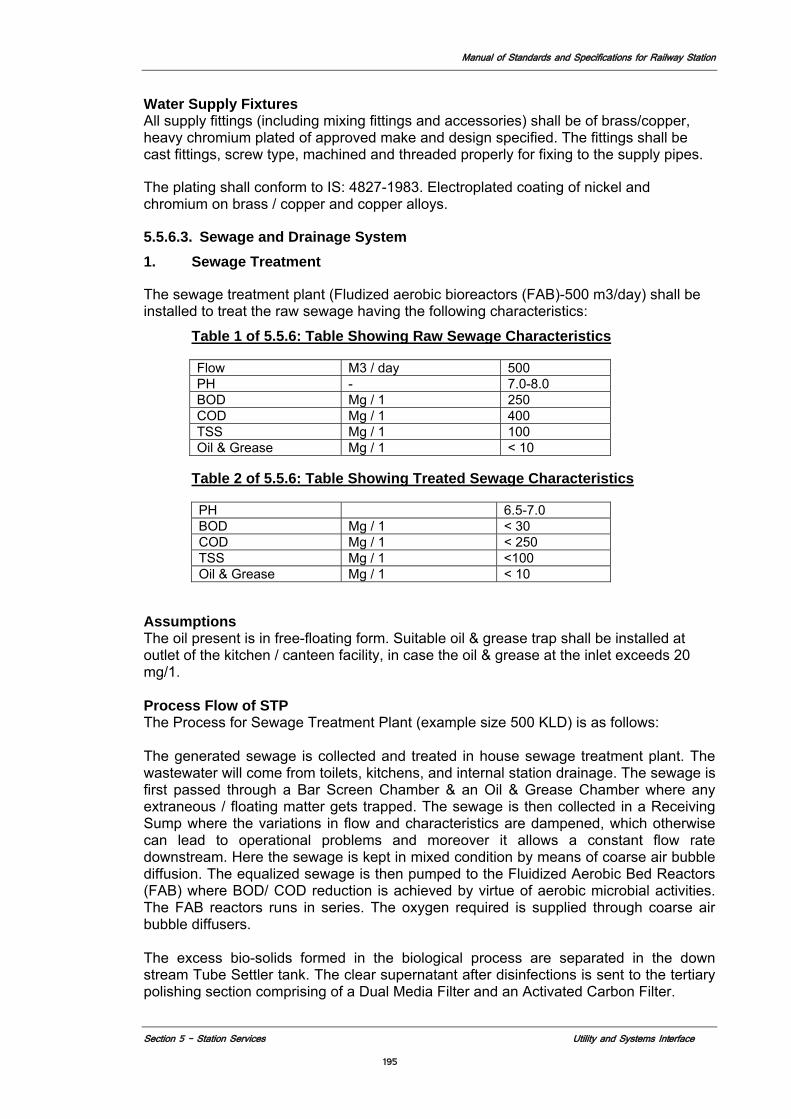
Manual of Standards and Specifications for Railway Station
Section 5 - Station Services Utility and Systems Interface
195
Water Supply Fixtures All supply fittings (including mixing fittings and accessories) shall be of brass/copper, heavy chromium plated of approved make and design specified. The fittings shall be cast fittings, screw type, machined and threaded properly for fixing to the supply pipes.
The plating shall conform to IS: 4827-1983. Electroplated coating of nickel and chromium on brass / copper and copper alloys.
5.5.6.3. Sewage and Drainage System 1. Sewage Treatment
The sewage treatment plant (Fludized aerobic bioreactors (FAB)-500 m3/day) shall be installed to treat the raw sewage having the following characteristics:
Table 1 of 5.5.6: Table Showing Raw Sewage Characteristics
Flow M3 / day 500 PH - 7.0-8.0 BOD Mg / 1 250 COD Mg / 1 400 TSS Mg / 1 100 Oil & Grease Mg / 1 < 10
Table 2 of 5.5.6: Table Showing Treated Sewage Characteristics
PH 6.5-7.0 BOD Mg / 1 < 30 COD Mg / 1 < 250 TSS Mg / 1 <100 Oil & Grease Mg / 1 < 10
Assumptions The oil present is in free-floating form. Suitable oil & grease trap shall be installed at outlet of the kitchen / canteen facility, in case the oil & grease at the inlet exceeds 20 mg/1.
Process Flow of STP The Process for Sewage Treatment Plant (example size 500 KLD) is as follows: The generated sewage is collected and treated in house sewage treatment plant. The wastewater will come from toilets, kitchens, and internal station drainage. The sewage is first passed through a Bar Screen Chamber & an Oil & Grease Chamber where any extraneous / floating matter gets trapped. The sewage is then collected in a Receiving Sump where the variations in flow and characteristics are dampened, which otherwise can lead to operational problems and moreover it allows a constant flow rate downstream. Here the sewage is kept in mixed condition by means of coarse air bubble diffusion. The equalized sewage is then pumped to the Fluidized Aerobic Bed Reactors (FAB) where BOD/ COD reduction is achieved by virtue of aerobic microbial activities. The FAB reactors runs in series. The oxygen required is supplied through coarse air bubble diffusers. The excess bio-solids formed in the biological process are separated in the down stream Tube Settler tank. The clear supernatant after disinfections is sent to the tertiary polishing section comprising of a Dual Media Filter and an Activated Carbon Filter.
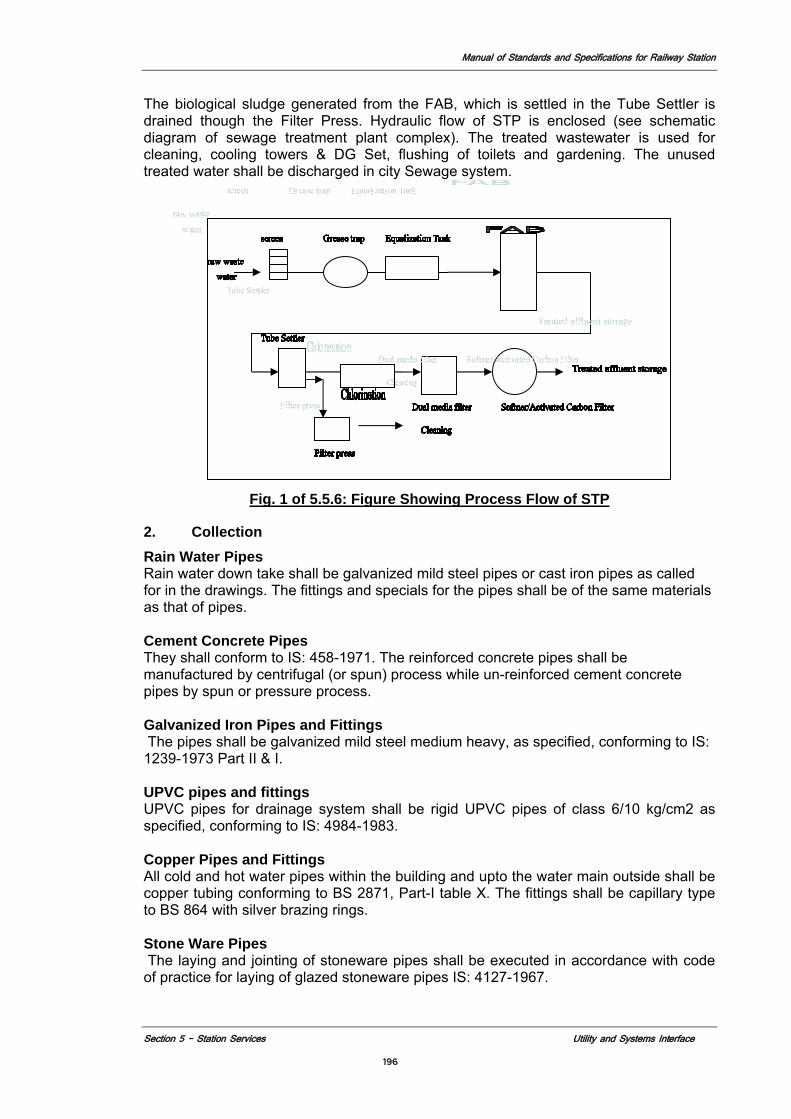
Manual of Standards and Specifications for Railway Station
Section 5 - Station Services Utility and Systems Interface
196
The biological sludge generated from the FAB, which is settled in the Tube Settler is drained though the Filter Press. Hydraulic flow of STP is enclosed (see schematic diagram of sewage treatment plant complex). The treated wastewater is used for cleaning, cooling towers & DG Set, flushing of toilets and gardening. The unused treated water shall be discharged in city Sewage system.
Fig. 1 of 5.5.6: Figure Showing Process Flow of STP
2. Collection Rain Water Pipes Rain water down take shall be galvanized mild steel pipes or cast iron pipes as called for in the drawings. The fittings and specials for the pipes shall be of the same materials as that of pipes. Cement Concrete Pipes They shall conform to IS: 458-1971. The reinforced concrete pipes shall be manufactured by centrifugal (or spun) process while un-reinforced cement concrete pipes by spun or pressure process. Galvanized Iron Pipes and Fittings The pipes shall be galvanized mild steel medium heavy, as specified, conforming to IS: 1239-1973 Part II & I. UPVC pipes and fittings UPVC pipes for drainage system shall be rigid UPVC pipes of class 6/10 kg/cm2 as specified, conforming to IS: 4984-1983. Copper Pipes and Fittings All cold and hot water pipes within the building and upto the water main outside shall be copper tubing conforming to BS 2871, Part-I table X. The fittings shall be capillary type to BS 864 with silver brazing rings. Stone Ware Pipes The laying and jointing of stoneware pipes shall be executed in accordance with code of practice for laying of glazed stoneware pipes IS: 4127-1967.
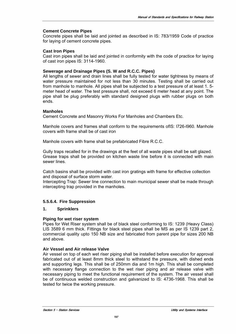
Manual of Standards and Specifications for Railway Station
Section 5 - Station Services Utility and Systems Interface
197
Cement Concrete Pipes Concrete pipes shall be laid and jointed as described in IS: 783/1959 Code of practice for laying of cement concrete pipes. Cast Iron Pipes Cast iron pipes shall be laid and jointed in conformity with the code of practice for laying of cast iron pipes IS: 3114-1960. Sewerage and Drainage Pipes (S. W and R.C.C. Pipes) All lengths of sewer and drain lines shall be fully tested for water tightness by means of water pressure maintained for not less than 30 minutes. Testing shall be carried out from manhole to manhole. All pipes shall be subjected to a test pressure of at least 1. 5-meter head of water. The test pressure shall, not exceed 6 meter head at any point. The pipe shall be plug preferably with standard designed plugs with rubber plugs on both ends. Manholes Cement Concrete and Masonry Works For Manholes and Chambers Etc. Manhole covers and frames shall conform to the requirements ofIS: l726-l960. Manhole covers with frame shall be of cast iron Manhole covers with frame shall be prefabricated Fibre R.C.C. Gully traps recalled for in the drawings at the feet of all waste pipes shall be salt glazed. Grease traps shall be provided on kitchen waste line before it is connected with main sewer lines. Catch basins shall be provided with cast iron gratings with frame for effective collection and disposal of surface storm water. Intercepting Trap: Sewer line connection to main municipal sewer shall be made through intercepting trap provided in the manholes.
5.5.6.4. Fire Suppression 1. Sprinklers Piping for wet riser system Pipes for Wet Riser system shall be of black steel conforming to IS: 1239 (Heavy Class) LIS 3589 6 mm thick. Fittings for black steel pipes shall be MS as per IS 1239 part 2, commercial quality upto 150 NB size and fabricated from parent pipe for sizes 200 NB and above. Air Vessel and Air release Valve Air vessel on top of each wet riser piping shall be installed before execution for approval fabricated out of at least 8mm thick steel to withstand the pressure, with dished ends and supporting legs. This shall be of 250mm dia and 1m high. This shall be completed with necessary flange connection to the wet riser piping and air release valve with necessary piping to meet the functional requirement of the system. The air vessel shall be of continuous welded construction and galvanized to IS: 4736-1968. This shall be tested for twice the working pressure.

Manual of Standards and Specifications for Railway Station
Section 5 - Station Services Utility and Systems Interface
198
Valves, gauges and orifice plates Sluice valves above 65mm shall be of cast iron body and bronze/gunmetal seat. They shall conform to type PN 1.0 of IS: 14846, valves upto 65mm shall be of gunmetal construction. Valve wheels shall be of right hand type and have an arrowhead engraved or cast thereon the direction for turning open and closing. Butterfly valves shall be slim seal type; lever operated confirming to BS 5155 Pressure gauge of suitable range shall be installed on the discharge side of each pump vacuum gauge shall be provided on suction side for pumps with negative suction. The gauges shall have brass cocks. Orifice plates shall be of 6mm thick stainless steel to reduce pressure on individual hydrants to operating pressure of 3.5kglsq.cm. Design shall be as per location and pressure condition of each hydrant. Sprinkler Heads Sprinkler heads shall be of quartzoid bulb type with bulb, valve assembly yoke and the deflector. a) Conventional Pattern: The sprinklers shall be designed to produce a spherical
type of discharge with a portion of water being thrown upwards to the ceiling. The sprinklers shall be suitable for erection in upright position or pendant position.
b) Spray Pattern: The spray type sprinkler shall produce a hemispherical discharge
below the plane of the deflector. c) Ceiling (flush) Pattern: These shall be designed for use with concealed pipe
work. These shall be installed pendant with plate or base flush to the ceiling with below the ceiling.
d) Side Wall Sprinklers: These shall be designed for installation along with, the
walls of room close to the ceiling. The discharge pattern shall be similar to one quarter of sphere with a small proportion discharging on the wall behind the sprinklers.
2. Hydrants External yard hydrants External yard hydrants shall be tapped from the Hydrant network with MS pipe stand post and 65NB GM oblique type single headed Hydrant valve conforming type A of IS: 5290-1977. The outlet shall be angled towards ground, with instantaneous spring lock type gunmetal female coupling of 63mm dia. for connecting to hose pipe. Internal Hydrants The internal hydrant outlet shall comprise 'single/double headed double outlet gunmetal landing valve' conforming to type AJB of IS: 5290-1977. Separate valves one on each of the two heads shall form part of the landing valve construction. A brass cap with chain is provided on one head of the outlet, which will have an instantaneous pattern female coupling for connection to the hosepipe. The landing valve shall be fitted to a tee connection on the wet riser at the landing.
Manual of Standards and Specifications for Railway Station
Section 5 - Station Services Utility and Systems Interface
199
3. Standpipe
Fire Standpipe system shall have an independent connection to water supply and not be connected to sprinkler system.
First Aid hose reel equipment First aid hose reel equipment shall comprise reel hose guide fixing bracket, hose tubing globe valve, stopcock and nozzle. This shall conform to IS: 884-1969. The hose tubing shall conform to IS: 1532-1969. The fixing brackets shall be of swinging type. Operating instructions shall be engraved on the assembly. Hosepipes, branch pipes and nozzles Hose pipes: - Hosepipes shall be rubber lined woven jacketed 63mm in diameter and 15m to type 2 (reinforced rubber lined) of IS: 636-1979. Branch pipe: - Branch pipe shall be of copper, gunmetal or aluminum alloy 63mm dia and be complete with male instantaneous spring lock type coupling for connection to the hose pipe. End couplings, branch pipes, and nozzles shall conform to IS: 903-1985. Hose Cabinet The hose cabinet to accommodate the hosepipes, branch pipe nozzle and the hydrant outlets shall be fabricated from 1.5mm thick sheet steel. In case of internal hydrants, this shall accommodate the hose reel equipment also.
4. Electrical Annunciation Sprinkler Panel: The equipment for control panel should be compact neatly wired and enclosed in a suitable 14-gauge M.S. sheetl16 CRCA sheet Metal Box that is suitably treated against corrosion. The control panel should be painted with over banked enamel paint. The panel shall consist of: Panel should be made in modules of 10 zones e.g. each module will have audible and visual indications and will monitor the circuit conditions. Suitable protection may be provided against charging of the battery over and above the specified values. Battery Unit The system shall be powered by lead acid storage stationery complete with automatic duel rate charger boost and trick operating from 220V, 50 Hz, single phase, mains supply. The battery capacity should be adequate for operation of the system connected to it for at least 24 hours in the non-alarm state followed by 30 minutes operation of all sounders and other connected equipments after a power (mains) failure.
Manual of Standards and Specifications for Railway Station
Section 5 - Station Services Utility and Systems Interface
200
The automatic charger should operate at the boost charge when the battery terminal voltage is less than about 2.1 V 20 per cell, and operate at a trickle charge rate of 100 to 200 HA, when the battery terminal voltage exceeds about 2.25 per cell. The connection to the 220V, 50Hz, single-phase system shall be through a three pin plug socket especially provided for the connection to the annunciation panel.
One battery unit complete with battery charger shall be provided for each control panel.
5.5.7. Heating Ventilation and Air Conditioning System shall consist of the following elements:
a. Air Conditioning b. Chillers c. Hot Water Generator d. Cooling Towers e. Chilled water Distribution f. Mechanical Ventilation g. Building Automated Systems (BAS) 5.5.7.1. Air Conditioning 1. Design Establish conditions and parameters of design. They include but are not limited to: Building orientation. Outside design conditions: (Example New Delhi) Season Dry bulb Temperature Wet bulb Temperature Summer 110 F (43.3 C) db 75 F (23.9 C) wb Monsoon 95 F (35 C) db 83 F (28.3 C) wb Winter 45 F (7.2 C) db 41 F (5 C) wb Station air conditioning systems design conditions shall be: Concourse air tempering 29o C 65% relative humidity (Incl. all waiting areas) Premium lounges air conditioning 23o to 26o (as per NBC) (Including any enclosed first waiting areas) Occupancy load Equipment load by season Station operation spaces requiring AC Lighting load by season Return air conditions by season Station Heat Gains Heat gains in station attributable to the heat releases from miscellaneous sources escalators, lifts, etc.
Air conditioning must be in an established technology available in India systems include Central chilled water system
VRV/VRF air-cooled outdoor units with reverse cycle capabilities (cooling and heating) for localized applications
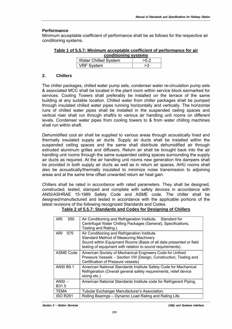
Manual of Standards and Specifications for Railway Station
Section 5 - Station Services Utility and Systems Interface
201
Performance Minimum acceptable coefficient of performance shall be as follows for the respective air conditioning systems.
Table 1 of 5.5.7: Minimum acceptable coefficient of performance for air conditioning systems
Water Chilled System >5.2 VRF System >3
2. Chillers The chiller packages, chilled water pump sets, condenser water re-circulation pump sets & associated MCC shall be located in the plant room within service block earmarked for services. Cooling Towers shall preferably be installed on the terrace of the same building at any suitable location. Chilled water from chiller packages shall be pumped through insulated chilled water pipes running horizontally and vertically. The horizontal runs of chilled water pipes shall be installed in the suspended ceiling spaces and vertical riser shall run through shaft/s to various air handling unit rooms on different levels. Condenser water pipes from cooling towers to & from water chilling machines shall run within shaft. Dehumidified cool air shall be supplied to various areas through acoustically lined and thermally insulated supply air ducts. Supply air ducts shall be installed within the suspended ceiling spaces and the same shall distribute dehumidified air through extruded aluminum grilles and diffusers. Return air shall be brought back into the air handling unit rooms through the same suspended ceiling spaces surrounding the supply air ducts as required. At the air handling unit rooms new generation fire dampers shall be provided in both supply air ducts as well as in return air spaces. AHU rooms shall also be acoustically/thermally insulated to minimize noise transmission to adjoining areas and at the same time offset unwanted return air heat gain. Chillers shall be rated in accordance with rated parameters. They shall be designed, constructed, tested, stamped and complete with safety devices in accordance with ANSI/ASHRAE 15-1989 Safety Code and ASME code. The chiller shall be designed/manufactured and tested in accordance with the applicable portions of the latest revisions of the following recognized Standards and Codes.
Table 2 of 5.5.7: Standards and Codes for Designing of Chillers
ARI 550
Air Conditioning and Refrigeration Institute. Standard for Centrifugal Water Chilling Packages (General), Specifications, Testing and Rating.)
ARI 575 Air Conditioning and Refrigeration Institute. Standard Method of Measuring Machinery Sound within Equipment Rooms (Basis of all data presented or field testing of equipment with relation to sound requirements).
ASME Code American Society of Mechanical Engineers Code for Unfired Pressure Vessels - Section VIII (Design, Construction, Testing and Certification of Pressure vessels)
ANSI B9.1 American National Standards Institute Safety Code for Mechanical Refrigeration (Overall general safety requirements, relief device sizing etc.)
ANSI - B31.5
American National Standards Institute code for Refrigerant Piping.
TEMA Tubular Exchanger Manufacturer’s Association. ISO R281 Rolling Bearings – Dynamic Load Rating and Rating Life.
Manual of Standards and Specifications for Railway Station
Section 5 - Station Services Utility and Systems Interface
202
Reference code: - ASHRAE 30-1995, ARI-560-92, and ANSI/ARI 550-92, ANSI/ARI 590-92 C743-93 The chiller packages shall be consisting of centrifugal compressor with factory fitted VFD/solid state soft starter, squirrel cage induction motor, water cooled condenser, chiller, refrigerant piping, wiring and automatic controls all mounted on a steel frame with all other accessories factory assembled and tested in line with the latest ARI/ Euro vent Standards. Centrifugal Compressor shall be single/double stage, open/semi-hermetic type, using Ozone compatible R-134a/R-123 refrigerant. The compressor shall be designed for a noise level not exceeding 88 dBA as per ARI-575 standard. 3. Air Handling Units and Cooling/Heating Coils Fresh Air Treatment Units (FATUs) shall be installed to supply filtered treated fresh air into various occupied spaces. The units shall be complete with Energy Recovery Wheels (ERW), active carbon filters, fine filters and Pre-filters. Air handling unit Design Parameters for selection of air handling units and its components: Maximum face velocity across filters 450 FPM (137 MPM) Maximum face velocity across coils 500 FPM (152 MPM) Maximum pressure drops across coils 15 feet Maximum water velocity across coils 6 FPS Maximum fan outlet velocity 2000 FPM (610 MPM) Maximum fan motor speed 1500 RPM Cooling /Heating Coils Selection of Coils Reference code: ANSI/ARI 510-93, ASHRAE 33-1978. Chilled/Hot water coils shall have 12.5 mm to 16 mm dia tubes of wall thickness not less than 24 G with aluminum fins of thickness not less than 37 SWG, firmly bonded to copper tubes assembled in zinc coated steel frame. Face and surface areas shall be such as to ensure rated capacity from each unit and such that air velocity across each coil shall not exceed 500 FPM. The coil shall be pitched in the unit casing for proper drainage. Each coil shall be factory tested at 21Kg/Sqcm air pressure under water. Tubes shall be hydraulically/ mechanically expanded for minimum thermal contact resistance with fins. Fin spacing shall be 11 to 13 fins per inch (4 to 5 fins per cm.) Material of construction for header associated with cooling coil shall be copper. MS bush shall be provided for affecting CHW pipe connections. 4. Fan Coil Units Fan coil units shall be of horizontal/vertical design and suitable for overhead/floor installation and necessary ductwork. The unit shall comprise of multirows deep chilled water coil made out of copper tubes of dia not less than 9.6mm OD having tube thickness not less than of 25 G. The cooling coil shall be complete with aluminum fins of minimum 0.2 mm thickness arranged to have a maximum fin spacing of 5 fins/cm and pressure tested for hydraulic pressure of 21 Kg/Sq.cm. Filters
Manual of Standards and Specifications for Railway Station
Section 5 - Station Services Utility and Systems Interface
203
Each unit shall be provided with a factory assembled filter section containing washable 50mm thick synthetic fibre (HDPE) type air filters having anodized aluminum frame as mentioned under subhead “Filters”. Viscous Metallic Filters Viscous metal filter shall be all metal, washable type. The filter media shall be composed of layers of crimped GI wire mesh. Synthetic Fibre Filters (EU-3) Synthetic fibre filter shall be constructed out of 50mm deep non-woven synthetic fibre replaceable media secured with anodized ductile aluminum mesh on one side & 40 sieve HDPE mesh on the other side. Microvee Filters: (EU-5) Fine filters shall be designed to remove particles down to 5 microns as per BS: 6540 standard. Filter shall comprise of aluminum sheet duly anodized. Equipment supplied must conform to recognized International Standards and be manufactured to ISO 9001, BS 5750 part 1 & 2 and carry the C.E. Mark on EMC Compliance. Fan Wheel Fan Wheel shall be forward/backward-curved non-overloading type. Pumps Pumps shall be as per IS: 1520 with latest revision IS: 325 Starter The critical speed of the pump shall be at least 30% above the rated speed. All pumps shall be provided with mechanical seals. Pumps shall be provided with flexible coupling. 5. Hot Water Generator The hot water generator shall be vertical/horizontal, shell type designed, constructed and tested for the specified water flow rates and temperature. The shell of the hot water generator shall be made out of MS sheet with electric fusion welded seams. The shell along with insulation shall be mounted inside a cabinet made out of angle iron framework, complete with 16 SWG MS sheet covers held with locks/bolts and hinges. The hot water generator shall be designed at 215 Psig and hydraulically tested in the factory at 325 Psig. The heaters shall be connected in a manner to provide capacity as follows:
Capacity Minimum Number of steps 101 KW to 300 KW 4-5 Steps 301 KW to 600 KW 5-7 Steps 601 KW to 1000 KW 8-10 Steps
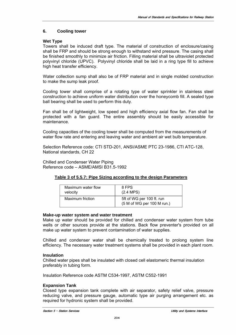
Manual of Standards and Specifications for Railway Station
Section 5 - Station Services Utility and Systems Interface
204
6. Cooling tower
Wet Type Towers shall be induced draft type. The material of construction of enclosure/casing shall be FRP and should be strong enough to withstand wind pressure. The casing shall be finished smoothly to minimize air friction. Filling material shall be ultraviolet protected polyvinyl chloride (UPVC). Polyvinyl chloride shall be laid in a ring type fill to achieve high heat transfer efficiency. Water collection sump shall also be of FRP material and in single molded construction to make the sump leak proof. Cooling tower shall comprise of a rotating type of water sprinkler in stainless steel construction to achieve uniform water distribution over the honeycomb fill. A sealed type ball bearing shall be used to perform this duty. Fan shall be of lightweight, low speed and high efficiency axial flow fan. Fan shall be protected with a fan guard. The entire assembly should be easily accessible for maintenance. Cooling capacities of the cooling tower shall be computed from the measurements of water flow rate and entering and leaving water and ambient air wet bulb temperature. Selection Reference code: CTI STD-201, ANSI/ASME PTC 23-1986, CTI ATC-128, National standards, CH 22 Chilled and Condenser Water Piping Reference code – ASME/AMSI B31.5-1992
Table 3 of 5.5.7: Pipe Sizing according to the design Parameters
Maximum water flow velocity
8 FPS (2.4 MPS)
Maximum friction 5ft of WG per 100 ft. run (5 M of WG per 100 M run.)
Make-up water system and water treatment Make up water should be provided for chilled and condenser water system from tube wells or other sources provide at the stations. Back flow preventer's provided on all make up water system to prevent contamination of water supplies. Chilled and condenser water shall be chemically treated to prolong system line efficiency. The necessary water treatment systems shall be provided in each plant room. Insulation Chilled water pipes shall be insulated with closed cell elastomeric thermal insulation preferably in tubing form. Insulation Reference code ASTM C534-1997, ASTM C552-1991 Expansion Tank Closed type expansion tank complete with air separator, safety relief valve, pressure reducing valve, and pressure gauge, automatic type air purging arrangement etc. as required for hydronic system shall be provided.
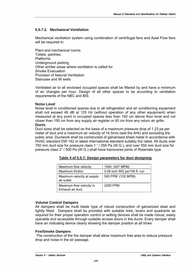
Manual of Standards and Specifications for Railway Station
Section 5 - Station Services Utility and Systems Interface
205
5.5.7.2. Mechanical Ventilation Mechanical ventilation system using combination of centrifugal fans and Axial Flow fans will be required in: Plant and mechanical rooms Toilets, pantries Platforms Underground parking Other similar areas where ventilation is called for Smoke Evacuation Provision of Natural Ventilation Staircase and lift wells Ventilated air to all enclosed occupied spaces shall be filtered by and have a minimum of air changes per hour. Design of all other spaces to be according to ventilation requirements of the NBC and BIS. Noise Level Noise level in conditioned spaces due to all refrigeration and air conditioning equipment shall not exceed 48 dB at 125 Hz (without operation of any other equipment) when measured at any point in occupied spaces less than 150 cm above floor level and not closer than 150 cm from any supply air register or 60 cm from any return air grille. Ducts. Duct sizes shall be selected on the basis of a maximum pressure drop of 1.23 pa per meter of duct and a maximum air velocity of 14.5m/s neat the AHU and excluding the public area. Ductwork shall be constructed of galvanised sheet metal in accordance with HVAC standard DW 142 or latest International standard suitably fire rated. All ducts over 750 mm duct size for pressure class 1 “ / 250 Pa (W.G.), and over 550 mm duct size for pressure class 2” / 500 Pa (W.G.) shall have transverse joints of Rolamate type.
Table 4 of 5.5.7: Design parameters for duct designing
Maximum flow velocity 1500 (457 MPM) Maximum friction 0.09 inch WG per100 ft. run Maximum velocity at supply air outlet
500 FPM (152 MPM)
Maximum flow velocity in Exhaust air duct.
2200 FPM
Volume Control Dampers All dampers shall be multi blade type of robust construction of galvanized steel and tightly fitted. Dampers shall be provided with suitable links, levers and quadrants as required for their proper operation control or setting devices shall be made robust, easily operable and accessible through suitable access doors in the ducts. Every damper shall have an indicating device clearly showing the damper position at all times. Fire/Smoke Dampers The construction of the fire damper shall allow maximum free area to reduce pressure drop and noise in the air passage.
Manual of Standards and Specifications for Railway Station
Section 5 - Station Services Utility and Systems Interface
206
Fire damper shall also be supplied with spring locked fusible link rated for 720 C (UL stamped) to close fire damper in event of rise in duct temperature. The fire dampers shall be mounted in fire rated wall. Actuators The actuator shall be maintenance free direct-coupled spring return type suitable to work on 24 V electric supply. 5.5.7.3. Building Automation System (BAS)
The Building Automation System shall be a PC-based System. It shall combine the latest state of the art technology with simple operating techniques and shall be used to control, manage alarms/reports and monitor the building services installations. The essential functions of the system are as follows: a. Centralized operation of the plant (remote control) b. Accepted Communication protocol – ASHRAE’s BACnet. Provide protocol
translator if they are using their proprietary protocol. c. Dynamic Graphic details of Plant and building d. Early recognition of faults e. Faults statistics for identification f. Trend register to identify discrepancies, energy consumption, etc. g. Preventive maintenance and plant servicing h. Optimum support of personnel i. Control optimization of all connected electrical and mechanical plant j. Prevention of unauthorized or unwanted access k. Own error diagnosis integrated system Room Thermostats: Room thermostats shall be suitable for mounting on British Standard conduit boxes. The operating differential shall not exceed 1oC, under all load condition. Room Temperature/Humidity Detectors: The temperature sensor shall have sensitivities such that a change at the detector of 0.2oC from the stabilized condition is sufficient to start modulating the corrective element. Immersion/temperature detector and duct mounted temperature/ humidity detectors Pressure Detectors (for liquids and gaseous media) Control valves (Modulating) Intelligent room control unit Where called for in the System Description Section, the terminals units (FCUs, etc.,) shall be controlled by individual (intelligent) room controllers. These IRC controllers shall accept an assortment of inputs and should have three slots for the different type of outputs depending on the application. These shall operate in the following modes: i. Comfort ii. Stand-By iii. Energy Hold-Off iv. It should be capable of accepting variety of inputs such as: v. Main temperature sensor (Room, etc.) vi. Auxiliary temperature sensor (Supply air, etc.) vii. Set point signal
Manual of Standards and Specifications for Railway Station
Section 5 - Station Services Utility and Systems Interface
207
An operator's terminal shall be provided to initialize the controller, read write the data and service the installation. It should be possible to communicate with all the controllers on a common bus from any controller on the bus. If required the controller should be able to operate in cascade mode with another controller. It should be possible to have special operating features such as un-occupied temperature reset, temperature set point adjustment, unit start/stop and operation at minimum volume via the Central BMS.A window should be provided to see the output cards. An LED shall be provided to indicate the healthy communication of the controller.
Manual of Standards and Specifications for Railway Stations
Section 6 Operation and Maintenance 208
Section 6
Operations and Maintenance
Manual of Standards and Specifications for Railway Stations
Section 6 Operation and Maintenance 209
6.0 OPERATIONS AND MAINTENANCE
6.1 Introduction
Modern railway stations are highly complex facilities, both physically and technologically. They must serve the needs of the customer during normal and emergency situations and must be operable and maintainable with minimal resources. The Concessionaire is to prepare a maintenance plan for the station project that addresses all aspects of the stations operation and highlights those areas that are the direct responsibility of the Concessionaire versus those that will be retained by MOR (See section 2.8). Based on this plan and as called for in section 5.4 the concessionaire will prepare a staffing plan that will also become part of the stations operation and maintenance plan. The staffing plan will also highlight the staffing expected to be provided by the Concessionaire versus the staffing to be assigned by MOR. The Concessionaire will also prepare an emergency response plan as outlined in section 4.2.3.8 that details the role the station staff in responding to various types of emergency conditions as defined in the plan. The plan will comply with the latest standards and codes of earthquake, disaster climate conditions and the like depending on the geographical location of the station. This emergency response plan shall be separate and distinct from the stations fire and life safety plan than shall comply with the life safety codes and standards noted in section 4.2 and coordinated with local fire fighting authorities. As new and redeveloped stations, they also must fit seamlessly into the existing Indian Railways operating system. The Railway system is a 24-hour, 7-day-a-week system, and operations and maintenance procedures are structured accordingly. The scope of this section gives general guidelines for the required design responses to operation and maintenance requirements of Railways, for stations only. It does not include detailed operational and maintenance procedures for track, systems, or equipment. The Concessionaire assumes responsibility for all maintenance and required staffing for the station facility for all functions as noted in division of concessionaire and MOR responsibility in section 2.8.
Details on the operations and maintenance procedures for the Railways system will be found in a project-specific operations and maintenance (O&M) plan to be developed by MOR schedule. This plan provides the O&M approach for new stations, so that all the planning and design of the stations can respond to these needs. It shall contain the following: 1. How the station operates under normal conditions (hours of operation: daily,
peak hours, weekends, holidays, special events, etc.)? 2. How the station will be staffed by MOR for normal peak and emergency
operations? 3. The roles and responsibilities of MOR staff 4. What facilities and systems will be required to support the activities of the MOR
operations staff?
References Station specific O&M plan for train operations – to be developed during the design. Indian Railways Works Manual, 2000, MOR
Station Working Rules Earthquake Code, 2006, India
Fire and Life safety Codes referenced in Section 4.2
Manual of Standards and Specifications for Railway Stations
Section 6 Operation and Maintenance 210
6.2 Maintenance 6.2.1 Goals and Objectives
Station maintenance activities are classified under the following headings: • Cleaning, Inspection and Reporting • Preventive Maintenance • Corrective Maintenance
Work on the first two categories takes place on a pre-scheduled routine and for the third on an as-needed basis. Design of the station must facilitate all maintenance activities. Basic design goals are as follows:
1. To create easily maintained environments with high level of cleanliness
throughout the system, which will instill pride and encourage use of the system. Materials shall be selected to be environmentally sustainable, provide long service life, be vandal-resistant and allow easy cleaning.
2. To provide facilities for an efficient maintenance program that operates at a minimum cost.
3. To facilitate replacement of damaged items, use of uniform interchangeable elements within each station or between stations.
4. To integrate maintenance elements in the stations as part of station design without detracting from the appearance of the stations.
5. General principles for operations and maintenance are as follows: 6. Routine maintenance should interfere as little as possible with normal station
operations and revenue service. 7. Maintenance and operation programs requiring use of the right of way areas
equipment, and flagging should be avoided. Necessary maintenance that must use these areas will require prior establishment of protocols with MOR.
8. Maintenance and Operation programs shall include all aspects of safety and health discussed in the section on Construction Requirements (7.5).
9. Station Cleaning involves the following: • Collecting and disposal of garbage, including any construction debris
generated from station operations • Cleaning fare collection and fare collection facilities • Cleaning, sweeping, and washing (including removing graffiti) the interior of
stations, including platform areas, passageways, elevators, stairs, wash rooms, toilets and related rooms and enclosures
6.2.2. Maintenance Plan
The maintenance plan developed by the Concessionaire for station shall contain at least the following elements: 1. Staffing plan identifying all maintenance classification positions that will be
available to address station maintenance needs. It shall include but not be limited to: a) Trade staff (plumbing, electrical, etc for equipment, maintenance and
repairs) b) Sanitation staff (general cleaning an sanitation) c) Supervisory staff (inspection, engineering, monitoring of controls, etc) d) Security staff (CCTV supervision, communications, access control etc.) e) Administrative staff (procurement of supplies and equipment, reports etc.)
Manual of Standards and Specifications for Railway Stations
Section 6 Operation and Maintenance 211
2. Service plan identifying all station elements requiring maintenance. Minimum requirements will be included as a schedule to the Concessionaires Agreement. It shall include but not be limited to: a) Description of computer based automated maintenance management
system that will be programmed to issue work orders with scheduled servicing of equipment and systems, and will be used by all station staff, both Concessionaire and MOR to report and record maintenance and repair requirements. System will be programmed for preparing status and productivity reports on all station activity besides general sanitation.
b) General sanitation by station area and component by frequency (sweeping, washing cleaning etc).
c) Maintenance and service requirements for all terminal equipment (lights, diffusers, ducts etc)
d) Listing of service provider requirements for specialized station components as the sewage and water treatment plans, air conditioning, control systems etc.
3. Description of building management system that will centrally monitor and control all environmental systems and energy consumption.
4. Organization structure for managing station maintenance staff and resources. 5. Solid waste collection and disposal plan (including waste from coached) 6. All O&M manuals and complete as built plans including all system control
diagrams. 7. Clean and waste water management program.
6.3 Operations 6.3.1 Goals and Objectives
The operation of the station will be a joint effort between the Concessionaire and MOR as the critical activity of managing the trains will be the sole responsibility of MOR while the managing of the movement of the passengers in through and out of the station will be the concessionaires responsibility with the exceptions noted in section 2.0. This will require a significant level of cooperation, which is essentially the first major goal of the station operations. Toward that end a sample list of the MOR offices for station operations is listed below. The definitive list will be included as a schedule in the concessionaire’s agreement. Indian Railways has several organizational departments that currently have direct responsibilities for various elements of the operation and maintenance of the railway system. These departments include:
Office of the Divisional Railway Manager (DRM)
Office of the Divisional Operation Manager (Sr. DOM) Office of the Sr. Divisional Engineer (Coordination) (Sr. DEN. Co-ord.) Office of the Sr. Divisional Electrical Engineer, (Sr. DEE)
Office of the Sr. Divisional Electrical Engineer, (General) Office of the Sr. Divisional Electrical Engineer, (Coaching) Office of the Sr. Divisional Electrical Engineer, (Traction Distribution) Office of the Sr. Divisional Electrical Engineer, (Rolling Stock Operation)
Office of the Sr. Divisional Signal and Telecom Engineer (Sr. DSTE) Office of the Sr. Divisional Mechanical Engineer (Sr. DME) Office of the Sr. Divisional Commercial Manager (Sr. DCM)
Manual of Standards and Specifications for Railway Stations
Section 6 Operation and Maintenance 212
The planning and design should respond to the activities of various departments. The above is only a sample list. Other areas include health inspection (food facilities), security Railway Protection Force (RPF) and Government Railway Police (GRP) to name two.
6.3.2 Operations Plan The operations plan developed by the concessionaire shall contain at least the following elements: 1. How the station operates under emergency conditions (station exiting,
emergency egress routes, location of areas of rescue, fire escape, locations of fire extinguishers, fire hose connections/cabinets, etc.)
2. How the security staff will manage access control to paid area and within paid area separations and establishment of security communications protocols between MOR and station staff.
3. Energy management program for station. 4. Management of all station amenities (lounges, waiting areas, commercial
concessions, cloak room, registered porters and trolleys, etc). 5. Administrative structure of Concessionaires management staff and
establishment of communications protocols 6. Quality control program which details inspection and oversight protocols for
compliance with maintenance objectives and recording and reporting system that will facilitate auditing by MOR. .
6.4 Design
In order to facilitate easy cleaning of stations, the following design principles shall be applied: 1. Drainage, runoff collection, treatment, and reuse of treated water, if provided, of
all station surfaces including platforms shall be incorporated into the station design. The station design shall not contribute in any way to the drainage requirements of the tracks.
2. Adequate quantities of drinking water of acceptable quality will be incorporated into the station design.
3. Collection and disposal of wastewater and any hazardous materials collected at the station shall be included in the station design.
4. Adequate water storage will be incorporated into the station design to provide water for firefighting or to supplement the city’s water system in case of a fire.
5. A cove base, integral with the floor, should be provided, or the floor finish should be turned up not less than 0.15m high at all points of intersection between floors and walls, partitions, columns, and other surfaces in all public areas.
6. Cleanouts and access panel shall be located inconspicuously and, where possible, placed in pipe chases and nonpublic areas.
7. Wall-mounted items of equipment, including movable items, shall be flush unless otherwise required to comply with ADA requirements.
8. Signs, handrails, benches, etc. shall be securely anchored with tamperproof screws or bolts with concealed fasteners in public areas.
9. Standard trash receptacles are to be installed adjacent to station entrances, concourses, platforms and walkways (see to section 4.6.)
10. Painting of surfaces shall be discouraged (see section 4.6.2.3). Concepts for maintenance of new stations shall be developed in consultation with Indian Railways. The planning and design shall respond to these maintenance requirements, including those of concessions, advertising, signage and other equipment.
Manual of Standards and Specifications for Railway Stations
Section 6 Operation and Maintenance 213
Concessionaire’s responsibilities include planning and design for maintenance of the following areas: 1. Ventilation and Air Tempering 2. UPE/OTE System 3. Plumbing distribution and fixtures 4. Elevators and Escalators 5. Station Power 6. Station Electrical 7. Station Lighting 8. Fire Detection and Alarm System 9. Fire Standpipe System 10. Sprinkler Systems 11. Gas Suppression Systems 12. Access Control and Intrusion Detection 13. Communications 14. Station Finishes 15. Station Structures
6.5 Maintenance Access
Design service access to avoid or minimize interference with normal station operations. Employee and public safety and health shall be of primary consideration in the maintenance process. Provisions shall be made in the design for the removal and replacement of elevators, escalators (including the escalator trusses), and other major equipment (fans, transformers, etc.) during the life of the station with minimal disruption of station and train operations.
Provide equipment delivery/maintenance/replacement routes for public and nonpublic area equipment and for escalator truss replacement. Provide lifting hooks/beams and access hatches where required to facilitate for equipment replacement.
In public areas, access hatches or panels shall be architecturally integrated. Access points for equipment delivery may be dependant on station construction type and depth. Major equipment, such as escalator trusses and transformers, may be delivered by work train and the design shall provide facilities to permit this.
6.6 Station Space Requirements and Configuration
General guidelines are given below. This is a sample list of rooms. Actual list will be developed as part of the space program called for in section 5.4. Each space to be used directly by MOR shall have the infrastructure requirements noted and shall be submitted to MOR for confirmation.
6.6.1 Operations spaces
1. Luggage Trolley areas Located at the main station access points in the unpaid area
2. Porters Room Rooms located in unpaid area for deployment of certified porters
3. Cleaner's Room s Provide at least one at every level in the station. Large concourse areas should
get a minimum of three or as required for deployment of sanitation staff for public spaces.
4. Refuse Rooms
Manual of Standards and Specifications for Railway Stations
Section 6 Operation and Maintenance 214
Refuse rooms shall be located throughout station and at platforms for the effective disposal of solid waste. On the platforms located beyond the passenger area and allow easy transport of refuse.
5. Maintenance Rooms a) Ladders, Lift and Scaffold Storage Rooms
Access tools, accessibility, and repair requirements for furniture, fixtures, and equipment maintenance will largely be dependant on the station configuration, ceiling height and overall architecture. Space requirements for equipment may be revised accordingly.
b) Replacement Supply Rooms Storage for items, such as lamps that require routine replacement as part of station operation.
c) Cleaner's Storage Rooms Storage for cleaner's cleaning supplies, such as cleaning agents and applicators. Provisions must be made to separate liquid and dry elements, and to ensure compatibility of the stored materials.
6.7 Sustainable Design Strategies
Better Operations and Maintenance is one of Indian Railways Five Pillars of Sustainable design (see to section 5.2.). Strategies for achieving sustainable design include:
6.7.1 Maintenance
Efficient use of maintenance materials to conserve resources. Specify maintenance materials that contain no known carcinogens, have low levels of VOCs and are non-toxic. Specify Low Emitting Materials. Specify Low Maintenance Materials. Selection of Materials
Use of energy efficient vehicles to service station (electric, hybrids, CNG) 6.7.2 Plan to Address Recycling
O&M plan to include storage and collection of recyclable materials. Encourage Collection of Recyclables.
6.7.3 Plan to Address Water Management
Conserve water while performing all station operation and maintenance activities. Provide washable aprons with appropriate cleaning systems (e.g., jet cleaning system) on all railroad tracks to clean the tracks and to ensure proper hygiene and sanitation.
Collect, treat, and recycle the wastewater generated from the cleaning of the tracks.
6.8 Infrastructure The management of the station will require significant attention to the maintenance of
the extensive infrastructure. Each of the major components of the station structure will require a comprehensive maintenance plan to keep the operation efficient and consistent with the aims of the station mission.
Automated management Maintenance System In order to manage, monitor, and report the maintenance/operation plan for the station
the Concessionaire shall provide a computer based automated maintenance management system. The system shall be programmed with the requirements of all the
Manual of Standards and Specifications for Railway Stations
Section 6 Operation and Maintenance 215
station components to automatically generate work orders for all required scheduled and preventive maintenance including all outside servicing requirements. It shall also take work order requests from station staff and shall have a real time monitoring of the completion of outstanding work orders and maintain a document trail on the issuance execution and completion of all work orders. System shall use a database type platform and all station administrative staff for both concessionaire and MOR along with supervisory maintenance staff shall be trained on the system.
Following are the components that need to be addressed in this plan
1. Electrical
Electrical system shall have preventive maintenance program for the following components Generators – Full load test every month witnessed and documented by designated station staff or certified service staff of an outside vendor. UPS system – System and components shall be tested at a frequency specified in manufacturers recommendation but not less than once a month Distribution boards – Protocols hall be set in place for the inspection of distribution boards for both when work is done on a board and for routine inspection of electrical distribution system. Lifts/escalators – Inspection schedule for over all system review and specific components will be developed based on manufacturer’s recommendations. Inspection and maintenance to be done by certified staff either in house or outside vendor. Fire Safety System – In addition to the regular monitoring and self-testing features of the fire safety system, outside vendors certified by the manufacturers shall come to review system in a frequency called for by their recommendations. Service shall be available on a maximum 24-hour response basis. In addition maintenance will require supply of replacement devices of each type so that defective devices are replaced immediately and the defective devices can be repaired as time permits. Security/Communications Systems – These system (CCTV, telephone, internet, PA, WiFi, Train information system) are constantly monitored and operational problems shall be programmed immediately into work order system. Outside vendors certified by manufacturer shall be available on a call for periodic review, and emergency service shall be available on a maximum 24-hour response basis. Maintenance shall be as with fire safety devices with supplies of replacement devices for immediate replacement. 2. Plumbing
Plumbing system shall have preventive maintenance program for the following components Water Supply – Water used at the station shall be monitored at source from locality, after treatment of harvested and recycled rainwater and after treatment of sewage water. Potable water shall conform to standards called for in section 5.2.6.2. Water for all other uses shall be acceptable as per the standards set by the engineering specifications of the station designer and conforming to all local codes and regulations.
Manual of Standards and Specifications for Railway Stations
Section 6 Operation and Maintenance 216
Pumping System – All pumps shall be maintained and serviced as per manufacturer’s recommendations by station staff or outside vendors. Redundancy requirements to facilitate maintenance shall be designed into the system so as to avoid any reduction in service while scheduled maintenance is taking place. Sewage System – Station will have a sewage treatment plant that will require assigned staff for monitoring process for recycling as well as discharge back into local system. Outside vendors with emergency response capabilities and any required certification by local utilities shall be on call to address any major system problems that cannot be managed by station staff. In addition protocols for the periodic cleaning of main lines shall be put in place to prevent back ups and blockages. Drainage -Protocols shall be put in place for the periodic cleaning of all storm drain collectors, manholes and main service lines to prevent back ups and blockages. Fire Suppression – Testing of fire suppression systems (sprinklers, hydrants, and standpipes) shall be as called for by applicable codes and ordinances but in no case shall the system be tested less frequently than every three months. Tests shall include pressure and tightness and systems shall be fully charged as required for the tests. All electrical and/ or mechanical controls shall be part of the test protocols. Outside vendors with emergency response capabilities and any required certification by local utilities, shall be on call to address any major system problems that cannot be managed by station staff. 3. Heating Ventilating and Air Conditioning
HVAC system shall have preventive maintenance program for the following components: Chillers – Establish protocols for the periodic inspection servicing and cleaning of units using station staff and outside vendors with the required manufacturer’s certification. Air Handling Units/Fan Coil Units - Establish protocols for the periodic inspection servicing and cleaning of units using station staff and outside vendors with the required manufacturer’s certification. Establish protocols for replacement of filters. Hot Water Generators - Establish protocols for the periodic inspection servicing and cleaning of units using station staff. Establish protocols for replacement of filters.
Manual of Standards and Specifications for Railway Stations
Section 7 Construction Management
217
Section 7
Construction Management
Manual of Standards and Specifications for Railway Stations
Section 7 Construction Management
218
7.0 CONSTRUCTION MANAGEMENT
7.1. General 7.1.1 This Section defines the principal requirements for the Concessionaire and the
Employer (MOR or its authorized representative) associated with construction of the Station.
7.1.2. Application of this Section
1. The requirements described below apply to all aspects of the Concessionaire’s Scope of Work, including all aspects conducted by the sub-contractors and all other agencies throughout the period of construction of the Station. This section shall apply to all construction activities, such as site management, project management, traffic management on road, passenger management at station, utility management, safety and health during construction, and quality assurance.
2. No construction activity associated with the contract shall be exempted from the
purview of this Section. A modified version, to be provided separately by the Employer, will be followed during the operation of the Station, including subsequent construction and repair and maintenance.
7.1.3 Targets and Goals
1. The objective of the requirements and guidelines included in this Section is to ensure that adequate precautions are taken to avoid unsafe and unhealthy environment at the construction site, to eliminate accidents, and to minimize environmental degradation during construction. Specific goals that the Concessionaire shall strive to achieve include:
a) Zero total reportable injuries and zero reportable environmental incidents
b) 0% incident recording and reporting
c) 100% initial and periodic training of all personnel in construction safety,
occupational health and environmental considerations
d) 100% compliance with all Plans submitted by the Concessionaire and approved by MOR or his authorized representative, such as the Diversion Plans, Quality Assurance Plan, etc.
e) 100% usage of Personal Protective Equipment (PPE), such as safety helmets, shoes, and glasses, fall protection, and other measures, such buddy system where appropriate when working in confined spaces, etc.
f) Total compliance with site inspections and audits, and timely correction of any deficiencies discovered
g) Usage of all possible and practicable means to minimize the damage, disturbance and annoyance to the environment, traffic, adjoining road users, and residents, and immediate corrective actions, as directed by the MOR or its authorized representative
Manual of Standards and Specifications for Railway Stations
Section 7 Construction Management
219
h) 100% coverage of all employees under the Workmen Compensation Act, and prompt payment of compensation to the workmen as and when the need arises
7.1.4 Reference Standards The Concessionaire and all other contractors shall develop thorough understanding of adhere to all pertinent Indian and International Standards and Codes listed in Section 1.11, and meet the requirements, standards and specifications given in this section for any construction activity to be undertaken for a station development project both for a new station and redevelopment of an existing station. If the requirements stated in this Section are less stringent than or in conflict with the country’s applicable legislation, the latter shall apply. The Concessionaire and the sub-contractors are strongly advised and encouraged to practice the principle of voluntary compliance.
7.2. Use of the Site Concessionaire shall prepare a site management plan (the “Site Management Plan”)
before start of any construction activity at a project site. Site Management Plan shall show the phase wise plans for use as work sites where Permanent/ Temporary works shall be executed (the “Work Site”) and construction depots where allied activities, such as fabrication, storage, office work, equipment and machinery maintenance etc. shall be carried out (the “Construction Depot”). Such areas shall be handed over to the Concessionaire as per an agreed site hand over plan. The Construction Site shall not be used for any purpose other than for carrying out the Works. Entry to and exit from the Site shall be controlled and limited only to the locations identified in the Site Management Plan approved by the MOR or its authorized representative. The Concessionaire shall be responsible to ensure that no disturbance to residents or damage to public or private property occurs from the use of the entry and exit locations.
7.2.1 Site Survey.
The Concessionaire shall survey the Site to establish precise boundaries and the existing ground levels within it. Photographs and videos of the Site shall be taken to provide a full record of the state of the Site before commencement of construction, with special attention to those areas that shall have to be reinstated/restored to original conditions. Heritage, religious, and historic sites that might exist within the site will either be left untouched or replaced, as approved by MOR or its authorized agent. The survey shall be carried out as agreed with the MOR or its authorized representative, prior to Site Clearance.
7.2.2 Clearance and Restoration.
The Concessionaire shall clear the Site as required by demolishing and removing vegetation, debris, trees along with their roots, buildings, etc. to approved locations either on or off the site as agreed by the MOR or its authorized representative. All Temporary Works which are not to remain on the Site after the completion of the project shall be removed prior to the project completion and acceptance as well as during the construction as instructed by the MOR’s Representative. Unless otherwise directed by the MOR or its authorized representative, all areas disturbed or affected by the construction activity, either inside or outside the Project Right of Way, shall be reinstated to their original condition, with new materials, including but not necessarily limited to, sidewalks, parking lots, access roads, adjacent roads and landscaping. The
Manual of Standards and Specifications for Railway Stations
Section 7 Construction Management
220
heritage material would be stored at a site approved by MOR or its authorized representative, and restored to the original locations under the supervision of the Archeological Society of India. The Concessionaire shall provide grass cover for any bare earth surface areas, along with proper provisions for surface drainage. Any landscaping work shall be properly designed to match the remaining areas and approved by the MOR or its authorized representative.
7.2.3 Permits The Concessionaire is responsible to obtain all necessary approvals and permits, and pay all associated costs required by the relevant agencies during the construction of the works.
7.2.4 Hoardings And Signboards
During construction, appropriate signs, signals, and barricades shall be installed to warn the general public as well as the workers, thereby preventing accidental injuries. 1. The Concessionaire shall erect hoardings, fences, and gates around its areas of
operations to prevent entry by unauthorized persons to his Works Area and shall issue identification cards to workers and staff. The photo identity cards of the size 85mm x 55 mm duly signed by the authorized representative of the Concessionaire. The fencing shall be corrugated metal or equivalent strength material, and shall be painted as directed by the MOR Representative. Similar barricades shall also be provided around all excavation, structural demolition and erection work, and similar activities, as directed by the MOR or its authorized representative/Engineer. No work shall commence until the MOR or its authorized representative has approved the barricades. All hoardings, fences, and gates constructed by the Concessionaire shall be removed at the completion of the Works, but only after MOR consent to remove them. Hoardings, fences, gates and signs that are to be left in place after completion of the Works shall be repaired and repainted as directed by the MOR or its authorized representative.
a. Hoardings/fencing will be maintained at all times, cleaned once/week,
and periodically painted to maintain its functionality. It can be reused as long as they are in good condition and approved by the MOR’s Representative.
b. The Concessionaire shall notify the MOR or its authorized
representative/Engineer eight (8) weeks prior to the date that it intends to install barricades, close a staircase and/or entry points, etc. to permit the MOR time to alert its customers.
2. The Concessionaire shall post informational signage four (4) weeks, or such
period as determined by the MOR Representative, in advance alerting customers of the upcoming shutdown of any staircases. The types, sizes, and locations of the project signboards shall be agreed with the MOR Representative before manufacture and erection. No advertising signs shall be erected or displayed at the Site. Directional signage, approved by the MOR or its authorized representative/Engineer, shall be posted by the Concessionaire on the day of the closures.
a. The Concessionaire shall furnish and install MOR-approved signage
(aluminum with plywood backing including mounting brackets) at locations in the station(s) as determined by the MOR or its authorized
Manual of Standards and Specifications for Railway Stations
Section 7 Construction Management
221
representative. In the event that the Concessionaire’s operations require the removal and replacement of any supporting elements, the Concessionaire shall submit the temporary supporting details to the MOR or its authorized representative/Engineer for approval prior to removal or replacement.
7.2.5 Temporary Construction.
All temporary Works, such as piling, foot over-bridges, site lavatories, etc. associated with the permanent Works shall be designed and operated as per good engineering practices and pertinent codes, and be approved by the MOR or its authorized representative. 7.2.5.1 Drainage and Sewerage. 1. All storm or rainwater from the Works Areas shall be collected and disposed of
by discharge to the nearest storm water drain or other water body, as required and approved by the MOR or its authorized representative. The Concessionaire shall investigate the treatment and reuse of the storm runoff collected from the Works Area.
2. Any damages to the drainage system or other installations within or adjacent to the Works Area shall be restored by the Concessionaire to the MOR’s or its authorized representative’s satisfaction.
3. Collection, storage, treatment, and disposal of sewerage and wastewater from the Works Area shall conform to local sanitation rules and regulations, and to the satisfaction of the MOR or its authorized representative.
7.2.5.2 Utilities 1. The Concessionaire shall provide all utilities (electricity, water, communication,
sewerage collection) to all contractors and subcontractors working at the Works Areas.
2. Potable water shall not be used for heating, cooling, humidification or vehicle washing without the written consent of the MOR or its authorized representative.
7.2.5.3 Underground Works Appropriately designed separate temporary retaining walls shall be used for supporting the excavated face of earth for all underground works of depth greater than 1.5m unless temporary wall itself is proposed to be used as a permanent wall, such as diaphragm wall. All temporary works shall be designed as far as possible to be removed when no longer required, and not left in the ground. Temporary works which are incapable of being removed shall be designed so that there will be no risk of ground settlement or other deleterious effects as a consequence of decay of timber or other material. External waterproofing membrane shall be provided to the base slabs and external walls of all underground structures so as to have a damp proof environment during the life time of the structure.
7.2.6 Care Of the Works
7.2.6.1 Generally, the Concessionaire shall perform all Works in dry weather. Additionally, the Concessionaire shall take all appropriate measures in accordance with
Manual of Standards and Specifications for Railway Stations
Section 7 Construction Management
222
its standing operating procedures (SOP) approved by the MOR or its authorized representative in order to protect the Works from elements, including rain, high winds, and extreme heat and cold so that the quality of work is not adversely impacted. 7.2.6.2 The Construction Site, equipment, and materials shall be protected from water damage by promptly removing any water on the Site or entering the site by using temporary drainage, pumping systems, or other appropriate methods to keep the Works free of water and to prevent settlement, flotation, and damage to new and existing structures. The Concessionaire will use traps to remove silt and debris from the water prior to discharging the effluent to drains, watercourses, etc. as approved by the MOR or its authorized representative. Storm restraint systems shall be provided by the Concessionaire to protect the partially completed and on going stages of construction in all weathers. 7.2.6.3 Construction shall be carried out in a manner so as to minimize damage to or interference with watercourses or drainage systems; utilities; structures including foundations; roads including street furniture or other properties; public or private vehicular or pedestrian access; monuments, trees, graves or burial grounds other than to the extent that is necessary for them to removed or diverted to permit the execution of the Project.
7.2.7 Spoil Removal
The Concessionaire shall ensure that all vehicular operations in and around the Works Areas conform to the local motor vehicle laws and regulations, as well as the Indian Railways circulars governing vehicular traffic at construction sites.
1. Only well-maintained and registered vehicles shall be allowed to be used for the
removal of excavated spoil from the sites.
2. The Concessionaire shall deploy qualified and trained personnel to identify and isolate any hazardous materials/dangerous goods from the construction sites, and dispose those off in an approved manner at sites specifically approved for the disposal of hazardous materials.
3. All drivers shall be medically fit and in possession of a valid and current driving license.
4. No vehicles, which are overloaded, shall be allowed to leave the site. The Concessionaire will provide a weighing station/bridge to measure and record weights of all loaded vehicles leaving the construction sites.
5. Any vehicles leaving the sites carrying loads which are liable to produce airborne contaminants shall prior to leaving the site securely sheet the load over in order to effectively contain any dispersion during transportation on the public highway.
6. The Concessionaire shall take appropriate measures that are approved by the MOR or its authorized representative to control dust, e.g., covering or protecting the loads, water wetting, where feasible) emanating from his stored debris as well as from loaded vehicles.
7. Vehicles exiting the site directly onto the live carriageway shall do so under the control of the clearly identified Traffic Controller.
Manual of Standards and Specifications for Railway Stations
Section 7 Construction Management
223
8. Vehicles that are required to reverse whilst on the site shall do so under the control of a trained flagman.
9. All vehicles prior to leaving the site shall have their wheels washed and any loose material removed, as necessary. The Concessionaire shall install a washing system in the construction area to prevent mud from going outside the Works Area.
10. Any spoil that is removed from the work-sites shall be disposed of only at authorized dumping sites, as approved by the MOR or its authorized representative. The Concessionaire shall design and implement a tracking (manifest) system to maintain records for the spoils removed to the dumpsites. No hazardous materials or dangerous goods shall be disposed of at the dumpsites.
11. Surfaced roads on the Site and leading to the Site shall not be used by tracked vehicles unless protection against damage is provided.
7.2.8 Site Security 7.2.8.1 The Concessionaire shall bear full responsibility for the security of the Works
Site in its possession. Only authorized persons shall be allowed to enter the Site, as discussed in Para 7.2.4(1), above. The Concessionaire shall, with the consent of the MOR or its authorized representative, designate areas for entry through the security fence, and shall provide gates and barriers at such entry points and maintain a twenty-four hour security guard to monitor the entry points. It will also provide security personnel and patrols elsewhere, as necessary, to maintain security of all contractors’/subcontractors’ work and equipment during the progress of the construction.
7.2.8.2 The Concessionaire, together with the MOR or its authorized representative,
shall implement a System to issue passes to any outsider or person/vehicle belonging to agencies other than the MOR or its authorized representative who may have to visit the Site in connection with work.
7.2.9 MOR or Its Authorized Representative’s Accommodation, Transportation, And
Radio Telephone Communication 7.2.9.1 The Concessionaire shall provide, erect, maintain, and remove the Site
accommodation for the use of the MOR or its authorized representative. The MOR will provide detailed requirements prior to the commencement of the Works. Prior to erecting the accommodation buildings, the Concessionaire shall obtain the consent of the MOR or its authorized representative for the accommodation including layout, equipping, and furnishings proposed by the Concessionaire. He will complete and equip the accommodation in sufficient time to allow the MOR or its authorized representative to occupy the accommodation prior to the commencement of both the temporary and permanent construction.
7.2.9.2 The Concessionaire will maintain the accommodation in a clean, stable and
secure condition, and clean it at least daily. A 24-hour security guard and an attendant during Office Working Errors shall be provided at each building for the MOR or its authorized representative.
7.2.9.3 The Concessionaire shall remove the accommodation or equipment with the
consent of the MOR or its authorized representative. The accommodation and
Manual of Standards and Specifications for Railway Stations
Section 7 Construction Management
224
equipment to left in position shall be repaired, repainted, and serviced before handing over to MOR, as instructed by the MOR or its authorized representative. All portable accommodation shall be moved at times instructed by the MOR or its authorized representative.
7.2.9.4 The Concessionaire shall provide office accommodation, furnishings and
equipment to the MOR or its authorized representative in case any portion of the Works is prepared or fabricated off-site.
7.2.9.5 The Concessionaire shall provide transport for the exclusive use of the MOR or
its authorized representative and his staff for any purpose in connection with the Works. 7.2.9.6 The Concessionaire shall provide, install, test, maintain, and remove at the end
of the Construction, a radio telephone communication system for the exclusive use of the MOR or its authorized representative.
7.3 Staging Plan The construction shall be staged and sequenced so that the existing station remains
operational at all times. This includes maintenance of all services to the operating facility as well as other infrastructure/services crossing the Site.
7.3.1 General
1. The Concessionaire shall, in order to reduce to a minimum any interference with
the convenient, safe and free use of the train platforms, passageways, stairways and other portions of the Railroad for customer traffic, perform the work affecting such portions, including the transportation of materials in and out of the Project Site, at such hours of the day and night as the MOR’s Representative may direct.
2. The Concessionaire shall submit the construction staging plan at least two (2)
weeks before commencement of the construction, based on the bar chart with durations for the diversions, street closure, shielding, elevators, duct bank, utility, temporary/permanent structure supports, electrical and communications cables for MOR approval. Prior to seeking the MOR approval, the Concessionaire shall coordinate the various aspects of the staging plans with the appropriate local authorities to minimize adverse impact on the surrounding communities. For example, a diversion or a street closure plan must be coordinated with the local civic authorities for approval by showing minimal disruption of the routine activities in the area, such as traffic patterns. The Concessionaire shall be responsible for providing the necessary relief or alternatives desired by the local authorities.
7.3.2 Electrical
1. The Concessionaire shall nominate a Representative whose name and qualifications shall be submitted in writing to the MOR's representative for review not later than 4 weeks before the appointment and who shall be solely responsible for ensuring the safety of all temporary electrical equipment on Site. The Concessionaire shall not install or operate any temporary Site electrical systems until this representative is appointed and has commenced duties. This
Manual of Standards and Specifications for Railway Stations
Section 7 Construction Management
225
representative shall obtain appropriate approvals from the MOR’s Chief Electrical Supervisor.
2. The Concessionaire shall inform the MOR or its authorized representative at
least ten (10) weeks in advance of any shutdown of electrical power, removal from service of any electrical systems or subsystems, and for any change or relocation of power or service within the Station. The Contractor shall provide a new temporary service capable of supporting all existing loads at the Station for the duration of this Project. In addition, backup power via diesel generators shall be provided by the Contractor during the period of power shutdown or equipment removal or relocation. The Contractor shall submit a detailed electrical bulletin request ten (10) weeks in advance of the placing into service or removing from service of any electrical equipment systems or subsystems and for any change or relocation of power within the station for the Engineer’s review and approval.
3. The Concessionaire shall not disrupt any existing electrical feeds or services that
are in operation at the existing Stations and shall ensure that all the electrical feeds continue to remain in operation 24 hours a day.
4. The Concessionaire shall notify the Independent Engineer eight (8) weeks in
advance of any work to be performed in an existing Electrical Distribution Room (EDR) or Communications Room so that appropriate Access and Protection (A&P) personnel can be scheduled to be present to witness the work.
5. All temporary electrical fittings and cables shall meet the Indian Standard
Institute’s Industrial Code.
7.3.3 Communications
1. Prior to removal of any telecommunication or signaling equipment, the Concessionaire shall obtain permission from the MOR, and shall meet all procedures as mandated by the appropriate Indian Railways Circulars. Before starting any excavation work, the Contractors/sub-contractors shall comply with the instructions issued in the Joint procedure order issued by the Indian Railways: Joint procedure order for undertaking digging work in the vicinity of underground signaling, electrical and telecommunication cables.
2. The Concessionaire shall coordinate with the telephone company to relocate any
public telephones. 3. The Concessionaire shall provide, install, test, maintain and remove at the end
of the Project, a radio telephone communication system for the exclusive use of the MOR or its authorized representative The Concessionaire shall be responsible for obtaining and making all payments in respect to all permits, licenses and charges involved in the provision and use of the radio telephone system and for ensuring that such arrangements are safe to use during the use of explosives in construction. The MOR or its authorized representative should be able to contact any one from his office to any parts of the Site, including the inside of the structures, such that 2-way, interference-free conversation is available at all times from the MOR or its authorized representative’s main office to any parts of the Site. The Concessionaire shall provide recharging facilities to allow for up to 8 handsets to be recharged at any time.
Manual of Standards and Specifications for Railway Stations
Section 7 Construction Management
226
7.4 Diversion Plan. The Concessionaire shall prepare a Traffic Management Plan to cope with the traffic disruption as a result of construction activities by identifying strategies for traffic management on the roads and neighborhoods impacted by the construction activities. The Concessionaire shall also prepare a detailed Utilities Diversion Plan. Both Plans shall need approval of the MOR or its authorized representative and be implemented throughout the whole period of the Contract.
7.4.1 Integrated Traffic Management Plan
The Concessionaire will prepare and implement throughout the whole period of contract a comprehensive Integrated Traffic Management Plan for approval by MOR. The purpose is to develop a Plan to cope with the traffic disruption as a result of construction activities by identifying strategies for traffic management on the roads and neighbourhoods impacted by the construction activities. The Plan will be in accordance with the agreed schemes following consultation with the Local Traffic Police and the other authorities in charge of the area. It will show the particulars of temporary traffic arrangements and control, arrangements for accommodating road and pedestrian traffic to ensure smooth traffic operations and for the safety of both construction workers and road users. The Concessionaire shall obtain all necessary approvals and extend all necessary help to the MOR or its authorized representative in obtaining such approvals without responsibility on the part of the MOR or its authorized representative to do so. The Concessionaire shall maintain close liaison with the Police and other civic authorities. It will ensure strict adherence to the MOR-approved Traffic Management Plan prepared in accordance with the local traffic laws, and ensure use of adequate safety and protection procedures (e.g., wearing high visibility clothing). 7.4.1.1. Principles for Developing the Plan. The basis for the Plan shall take into consideration the following principles: a. minimizes the inconvenience and ensures safety of the road users b. minimize the interruption of surface traffic in the area(s) impacted by
construction while ensuring traffic safety, and c. facilitate access to the construction site with minimal impact on the progress of
construction work. 7.4.1.2. Measures to Be Considered The Plan shall consider different measures to include, but not limited to, the following to accommodate road and pedestrian traffic at individual construction sites and continuously along the alignment, to ensure smooth traffic operations and safety of workers and road users: a. The use of top-down construction at the station sites to reduce the period of
disruption to road users b. Proper phasing and timing of traffic signals c. Modifications to intersection geometry d. Changes in lane usage e. Parking prohibitions f. Re-location of bus stops g. Reduction in carriageway width h. Right-turn prohibition
Manual of Standards and Specifications for Railway Stations
Section 7 Construction Management
227
i. Work site access management j. Minimizing the duration of any road closure k. Reversible lane operations l. Modification of roadway alignment affected by the construction, which shall be in
conformance with the requirements and regulations defined by the relevant authorities
m. Other appropriate and applicable traffic engineering measures 7.4.1.3 Right Of Way a. The Concessionaire shall manage the vehicular and pedestrian right of way
during the period of construction. He shall take into account all possible considerations to fulfill the need to maintain essential traffic requirement. Such considerations include: maintaining emergency access to all properties and maintaining access to business premises and properties to minimize disruptions; separating the construction traffic from other traffic insofar as possible; incorporating utilities diversions in the traffic management plan where applicable; protecting pedestrians, motorists, workmen and plant and equipment from accidents at all times; not fully closing any roads or intersections that have no alternative access; following the local regulations for the minimum lane widths of fast and mixed traffic lanes; etc.
b. Site vehicles exiting the site shall observe caution at all times; if the vehicles are
exiting directly onto the live carriageway then they shall be directed by an identifiable Traffic Controller.
c. Traffic Controllers shall be available for directing vehicles that are exiting the sites
directly onto the live carriageways. Any vehicles entering the sites that are required to execute reversing maneuvers shall do so under the strict control of a trained and designated banksman.
7.4.1.4 Signage a. Adequate signage shall be provided to ensure that motorist receive all needed
information for traffic diversions. Adequate and clear warning signs shall be displayed at appropriate distances before the commencement of the site workings. In addition, prior warning shall be given concerning the location of the approaching site entry and exit points.
b. All traffic signs, barriers, cones and lighting shall be kept maintained and clean
at all times. When concrete barriers are used to separate flows of traffic, the barriers shall be in a continuous unbroken line. No gaps shall be left between any sections of the barrier.
7.4.1.5 Inspections
Regular inspections of the traffic management schemes shall be conducted by the Concessionaire, contractor, and the subcontractors in both the daytime and nighttime hours with the results of these inspections being recorded. These records shall be kept available for inspection by the MOR or its authorized representative. 7.4.1.6 MOR Consent At least 4 weeks before the traffic arrangement and controls are implemented, the Concessionaire shall obtain consent of the MOR or its authorized representative for his
Manual of Standards and Specifications for Railway Stations
Section 7 Construction Management
228
proposal containing the following information: a. Details of traffic diversions and pedestrian routes b. Details of lighting, signage, guarding and traffic control arrangements and
equipment c. Any conditions or restrictions imposed by traffic police or other relevant
enforcement authorities.
7.4.2 Utilities Diversion Plan
1. The Concessionaire shall prepare a Utilities Diversion Plan and submit the same with the preliminary design for approval by the MOR or its authorized representative. The Concessionaire shall make his own inquiries and investigations, including excavating trial holes, to ascertain the existence, nature, location, and size of the utilities. The utilities shall be supported in place as far as possible and practicable. The Diversion plan shall outline all utilities likely to be affected by the project and list the utilities proposed to be diverted and those to be supported for which the Plan will further identify localized temporary diversions. The MOR or its authorized representative may require the Concessionaire to demonstrate that the proposed diversion is the most cost-effective alternative.
2. The Concessionaire shall immediately inform the MOR or its authorized
representative and the utility agencies of any damage to utilities, leakage from utilities, and discovery of utilities not previously identified.
3. The Concessionaire shall keep records of the existing utilities encountered and
provide a copy to the MOR or its authorized representative. The record shall contain the following information: location of utility; date the utility was found; nature, size, and condition of the utility; and support provided or diversion made – temporary or permanent.
7.5 Safety Requirements during Construction
1. The Concessionaire shall comply with all Safety and industrial health legislation including, without limitation, The Rules and Regulations of the National Safety Council of India. The Concessionaire shall be fully responsible for the safety of the project site, his personnel, contractors’ and subcontractors’ personnel, public, and all persons directly or indirectly associated with the project, or on or in the vicinity of the project site. The Concessionaire shall treat safety measures as a priority in all activities throughout the execution of the project.
2. The Concessionaire shall keep on the Site copies of safety and industrial health
regulations and documents, such as Material Safety Data Sheets (MSDS) or equivalent information about the materials being used on the Site. Pertinent regulations and documents shall be translated into languages which are understood by the operators engaged by the Concessionaire unless exempted by the MOR or its authorized representative, and such translations shall be displayed or kept alongside those in Hindi and English languages.
7.5.1 Working In The Vicinity Of the Live Railroad. The Concessionaire and sub-contractors, and their employees shall:
Manual of Standards and Specifications for Railway Stations
Section 7 Construction Management
229
1. Follow the requirements of Section 3.2, working near Running Line, joint procedure order for undertaking digging work in the vicinity of underground signaling, electrical and telecommunication cables, Indian Railways.
2. At all times while working on or adjacent to tracks closely observe the applicable
flagging rules and all other applicable MOR rules and regulations as listed in the Railways Manuals to be provided by the MOR at the kick-off meeting.
3. Not allow any person to encroach onto the railway unless specifically authorized
by the MOR. 4. Propose working methods and schedules for all work in and around the Railroad,
in accordance with the provisions herein specified and referred, for the approval of the MOR or its authorized representative. Such methods and schedules shall allow for the safe and continuous operation of the Railroad, without any interruption of service or change in regular schedules of train operation, except as may be hereinafter specified with the written permission to proceed from the MOR. Requests for diversion of train service or use of a MOR work train or crane by the Concessionaire to complete its work shall be submitted to MOR at least six (6) weeks in advance, and will delineate all necessary details regarding the work to be completed. The Concessionaire will refund the MOR for use of MOR assets.
5. Require all persons to wear high visibility clothing at all times. During the
performance of work on or adjacent to operating train ways, employees of the Concessionaire or its sub-contractors will not be permitted to wear reflective clothing, or to apply any reflecting substance to their clothing, tools, or other equipment, the predominant color of which conflicts with colors in use in the operational procedures of the MOR.
6. Require the Concessionaire to ensure that all its employees or those of the sub-
contractors have received training and certification to working in the vicinity of live railroad.
7. Require all workers to have adequate protection in accordance with the
Employer’s requirements (provision of block inspectors, flagmen, and lookouts, etc.)
7.5.2 Working Along The Right Of Way (Row)
The Contractor shall ensure that all of his employees and those of his Subcontractors fully understand and comply with the provisions of applicable MOR Flagging Rules and MOR Safety Rules, before working on or adjacent to any operating track
7.5.3 Safety Requirements For Crane Operation The Contractor shall ensure that all of his employees and those of his Subcontractors fully understand and comply with the provisions of applicable MOR Crane Operation Rules and MOR Safety Rules, before working on or adjacent to any operating track
7.5.4 Working at Height. The Concessionaire shall take all appropriate measures to ensure that whenever
workers are working at a height, from which they can fall more than two meters (6 feet), suitable safety precautions have been taken to avoid serious injury to the workers.
Manual of Standards and Specifications for Railway Stations
Section 7 Construction Management
230
7.5.4.1 Scaffoldings. a. The Concessionaire shall construct appropriate Light or Heavy duty scaffoldings
of sound materials free from patent defect, and have it erected and dismantled by thoroughly trained and experienced workmen.
b. The Concessionaire shall inspect and record all scaffolds on a regular, periodic
basis and make the inspection results for checking by the MOR or its authorized representative. Specifically, the scaffolding should be securely fixed to existing structures or adequately buttressed; i) Barrels, boxes, loose tiles or other unsuitable material shall not be used
as supports for working platforms; ii) All working platforms shall be fully boarded, be provided with toeboards,
have guard rails at one meter height, with an intermediate rail at half height; and be kept free of unnecessary obstruction or rubbish
iii) Secure ladder access shall be provided. Use of ladders will conform to the specifications outlined in 29 CFR 1926.1053, IS 3696 Part 1 & 2, and other relevant Indian Safety and Health Codes and Regulations.
iv) All ladders shall be of sound construction and shall be free from patent defect.
v) Ladders should be checked weekly and defective ladders shall be promptly and properly repaired or replaced.
vi) Ladders shall not be used as working platforms but may be used for work of short duration of up to thirty minutes.
vii) Metal ladders shall not be used near or adjacent to overhead powerlines. viii) Ladders shall be secured at the top or footed at the bottom to prevent
slippage; not be used if any rung is missing; not be used for any other purpose than to provide access; be set at an angle of seventy five degrees unless designed for vertical access
7.5.4.2 Safety Harnesses/Fall Arresters
a. Where it is not possible to provide a safe working platform, the use of safety
harnesses may be considered. If safety harnesses are used, they should be of the full body type and secure anchorage points shall be provided and used.
b. For some of the more difficult situations where work at height is necessary and the provision of working platforms is not practicable, Concessionaire should give consideration to the use of fall arrest devices to provide a safe system of work.
7.5.5 Working in Confined Spaces
1. Contractors will ensure that no work will be undertaken in Confined Spaces unless a Permit to Work has been prepared and issued.
2. Only persons who have been thoroughly trained, experienced and are physically fit shall be allowed to work in Confined Spaces.
3. Persons with any of the following medical conditions shall not be allowed to work in confined spaces.
7.5.6 Working with Compressed Gas
7.5.6.1 Storage The Concessionaire will store all compressed gases, such as oxygen and fuel gases, in a safe manner in keeping with the following requirements;
Manual of Standards and Specifications for Railway Stations
Section 7 Construction Management
231
a. When not in use, compressed gas cylinders should preferably be stored in the
open air in a well ventilated area at ground level on a firm level surface at least 3 m away from any cellars, drains, excavations or other hollows where vapor may collect. There should be good access to the area, which should be kept clean and clear of combustible material, including wood, packing materials and vegetation. If any protection is provided to prevent cylinders being exposed to the weather, it should be of non-combustible material and should not inhibit ventilation. The area should not be close to any source of heat.
b. If storage in the open air is not reasonably practicable, compressed cylinders
must be stored in adequately ventilated storerooms. The storeroom must be constructed of non-combustible material.
c. Liquefied Petroleum Gas (LPG) cylinders should be stored separately from
oxygen cylinders, other flammable liquids, oxidising materials such as sodium chlorate, and toxic or corrosive substances. Such materials should be kept at least 3 meters away from LPG cylinders.
d. It is important that the valves of so-called `empty' cylinders are kept closed as
well as those of full cylinders and that plugs, shrouds and caps are kept in place on all cylinders. This is necessary not only to prevent the escape of any residual compressed gas into the atmosphere but also to ensure that air is not sucked into the cylinder to form an explosive mixture inside it. All cylinders should be stored with their valves uppermost. Storage of LPG cylinders on their sides is particularly hazardous as in the event of a leaking or inadequately closed valve there is the possibility of leakage of liquid and a consequential release into the atmosphere of far greater quantities of flammable vapour.
7.5.7 Welding and Cutting
The Concessionaire and the subcontractors shall ensure that all welding, cutting and gouging is carried out so that the risks are kept at a minimum. There will be some circumstances when Permits to Work will need to be issued.
7.5.8 Plant and Equipment
The contractor shall ensure that only safe and well-maintained plant and equipment shall be allowed to operate on any of the sites.
1. All operators of heavy plant shall be medically fit, over eighteen years of age and be thoroughly trained and experienced to operate the equipment.
2. No unauthorized person shall be permitted to ride on plant. 3. The operators shall conduct daily inspections of their respective items of plant
with the results of these inspections being recorded and the records kept available for inspection by the Employer’s Representative.
4. All mobile heavy plant shall be equipped with at least one 5kg Dry Powder Fire Extinguisher, carried at a suitable position so as to ensure its easy availability.
5. Whenever heavy plant is operating in congested areas, thoroughly trained and experienced banksmen shall be deployed to control the plant and personnel movement and interface.
6. Any waste engine oil and filters following any on site servicing and maintenance shall be removed from the sites and disposed of in an environmentally conscious manner at authorised disposal locations.
Manual of Standards and Specifications for Railway Stations
Section 7 Construction Management
232
7. All drums of fuel oil shall be stored on drip trays or the fuel shall be kept in bonded bulk storage fuel tanks, with quantities stored being kept to a minimum.
8. The storage areas shall have dry powder fire extinguishers positioned in close proximity to their location for use in an emergency.
9. The Contractor shall ensure that all gears, revolving shafts, flywheels, couplings and other dangerous parts of machinery shall be effectively guarded unless they are so constructed, installed or placed as to be safe as if they were guarded.
10. Fencing of dangerous parts of machinery shall not be removed while the machinery is in use or in motion. If the fencing is required to be removed for maintenance purposes it shall be replaced before the machine is taken into use.
11. The Contractor shall ensure that all machinery used on site is in safe condition and is properly maintained and repaired by duly authorised, thoroughly trained and experienced persons.
12. Transportation of equipment/material to and from construction barricaded areas shall only be done during the off peak hours, and as approved by the Engineer. During the course of work, the Contractor shall protect the existing architectural finishes including, but not limited to, all wall tiles, and metal railings and any existing, rehabilitated and new equipment to the satisfaction of and as directed by the MOR Engineer. Any equipment and architectural finishes that are broken or damaged shall be promptly repaired or replaced by the Contractor as approved by the Engineer at no additional cost to the MOR.
7.5.9 Demolition
1. The Contractor shall ensure that all demolition works shall be carried out in a controlled manner under the management of experienced and competent supervision.
2. Prior to any demolition commencing, a survey shall be conducted to identify if there are any hazardous materials present, for example the presence of materials such as asbestos and lead
3. If any hazardous materials are found, then consideration shall be given as to whether they shall need to be removed by a Specialist Agency or Sub-contractor prior to the main demolition works commencing.
4. Before the demolition commences all relevant notifications shall need to be given to the local authorities and media.
5. Measures for protection to the public shall be required to be put into place in order to give protection from any possible falling debris and dust generation.
6. All power supplies and services shall be disconnected before any demolition work commences.
7.5.10 Hazard Identification and Risk Assessment
1. The purpose of Hazard Identification and Risk Assessment is to identify all the significant hazards, which may occur during the construction phase, and to rank them according to their severity. Having ranked the risks by severity the Contractor shall then introduce measures to mitigate the effects of that risk.
2. Prior to the commencement of any potential High-Risk operations the Concessionaire shall conduct a detailed hazard analysis and risk assessment of the task and shall record his findings on appropriate worksheets for review by
Manual of Standards and Specifications for Railway Stations
Section 7 Construction Management
233
the MOR or its authorized representative.
3. The worksheets should then show what measures the Concessionaire is going to take to reduce the level of risk to acceptable levels.
4. Method Statements. As a result of the Hazard Identification and Risk Assessment, detailed method statements shall need to be produced for medium and high risk activities to enable the task to be undertaken safely. The method statements should contain at least the following information: a) Introduction – A brief outline of the Task b) Details of the Risks involved c) Step by step description of how the task is to be undertaken detailing d) What needs to be done; e) The order in which the task will be carried out; f) What plant or equipment is required; g) Who the task will be done by;
i) Who will supervise the task; ii) Where will the task take place; iii) When will the task take place; iv) The precautions which must be taken before the task is
undertaken; v) What to do if things go wrong;
7.5.11 Permits to Work
1. The Concessionaire shall develop a permit-to-work system, coordinated with required local authorities and all applicable codes and regulations. It will be a formal written system used to control certain types of work that are potentially hazardous. A permit-to-work is a document, which specifies the work to be done, and the precautions to be taken. Permits-to-work form an essential part of safe systems of work for many construction activities. They allow work to start only after safe procedures have been defined and they provide a clear record that all foreseeable hazards have been considered. Permits to Work are usually required in medium- and/or high-risk areas as identified by the Risk Assessments.
2. A permit is needed when construction work can only be carried out if normal safeguards are dropped or when new hazards are introduced by the work. Examples of high risk activities include but are not limited to: a) Entry into Confined Spaces. b) Work in Close Proximity to Overhead Power lines and
Telecommunication Cables. c) Hot Work. d) To dig where underground services may be located. e) Work with moving construction locomotives. f) Working on Electrical Apparatus. g) Work with Radioactive isotopes.
7.5.12 Personal Protective Equipment (PPE)
1. General. The Concessionaire shall be responsible maintaining healthy working conditions for all his and his contractors and sub-contractors, workers. In particular he shall pay attention to the effects of noise, dust, air pollution and the use of chemicals. If it is not possible to remove the cause of harm then suitable
Manual of Standards and Specifications for Railway Stations
Section 7 Construction Management
234
and sufficient Personal Protective Equipment (PPE) should be provided to those workers who could be affected.
2. If the use of PPE is the only means of providing protection the Contractor shall ensure that all the workers affected are properly trained in the use of the PPE and that adequate supervision is provided to ensure its proper use.
3. The Concessionaire personnel shall wear personal protective equipment (safety vest, hard hat and safety glasses) while working. The personal protective equipment shall conform to 29 CFR 1926.95 and the appropriate Bureau of Indian Standards and be approved for use in the MOR requirements. A written personal protective equipment program must be established as a part of the Concessionaire’s safety and health program and the site-specific safety and health plan.
4. Head protection will be mandatory in the construction areas in accordance with 29 CFR 1926.100; other PPE shall be used as determined by the Concessionaire’s Safety Officer in conjunction with the MOR and other appropriate authorities. All sites shall be designated as HARD HAT SITES and as such an adequate supply of safety helmets shall be kept available for use by authorised visitors to the sites.
5. The Contractor shall at all times keep and maintain an adequate supply of suitable personnel protective equipment which shall be readily available for use at all times on the sites, and would include amongst others the following items: a) Head Protection (safety Helmets). Certified hard hats meeting the ANSI
Z89.1 1997 requirements or equivalent Indian Safety Council requirements for Type I Class E protection shall be properly worn, and maintained - (no bump caps or cowboy type hard hats)
b) Foot Protection (Safety Footwear, Gumboots, etc.). Shoes shall be in good condition without breaks or splits, at least six inches high, (preferably leather with safety toe), and be completely laced or buckled. The shoe shall have defined heels that are no more than one inch high (sneakers/gym shoes are prohibited). The sole shall be at least ¼” thick at all points and provide good traction under slippery conditions.
c) Body Protection (High visibility clothing as per BS EN 471:1994 (waistcoat/jacket), Apron, etc.). All Contractor employees exposed to vehicular traffic or motorized moving equipment, shall wear flame retardant safety vests that have 360-degree reflective visibility, and 100% rip away capabilities. The front of the vest shall be fitted with a transparent plastic pocket, flush mounted, to accommodate a photo ID. The Concessionaire and all sub-contractors shall utilize safety vests with a label on the front and back identifying them as a “Concessionaire”.
d) Hearing Protection (Ear plugs, ear muffs, etc.) e) Respiratory Protection (nose mask, Self-contained Breathing Apparatus,
etc.) f) Eye Protection (Goggles Welders glasses, etc.); grinding or chipping
shall require a face shield g) Personal fall protection (Full body harness, Rope-grip fall arrester, etc.) h) Other PPE, as required.
6. The Concessionaire shall not pay any cash amount in lieu of the PPE to the
workers/sub-contractors and expect them to buy the same for use during work.
Manual of Standards and Specifications for Railway Stations
Section 7 Construction Management
235
7. The Concessionaire shall at all times maintain a minimum of 10% spare PPEs and safety appliances and properly record and show to the Employer during inspections. Failing to do so shall invite appropriate penalty established by the Employer as per the provisions of the Contract.
8. The Concessionaire shall establish a Medical Surveillance program for all workers required to use PPEs so their exposures to hazards (e.g., hazardous substances, noise, carbon monoxide, etc.) can be monitored during their assignment on the project. Records of the medical surveillance shall be maintained to protect the Concessionaire, sub-contractors, and the Employer against frivolous claims.
9. The Contractor shall remove from the site any worker who consistently refuses to wear the appropriate personal protective equipment.
7.5.13 Hazardous Noise
1. Industrial deafness is caused by over exposure to high levels of noise from plant, machinery or construction processes. Once a part of a persons hearing has been lost it can never be recovered. Deafness can also lead to further accidents on site with workers being unable to hear warnings and other instructions.
2. For continuous exposure, i.e., for eight hours in any one day, the sound level should not exceed the background plus 5 dB (A). For non-continuous exposure a calculated equivalent continuous sound level (Leq) should not exceed background noise plus5 dB (A). Workers should not be exposed to sound levels exceeding background plus5 dB (A) unless they are wearing suitable hearing protectors, which effectively reduce the sound level at the user’s ear to acceptable levels.
3. If Peak noise levels exceed 120 dB (A) then the wearing of suitable hearing protectors shall be Mandatory.
4. The Contractor shall carry out noise assessments to establish what noise levels his workers are being exposed to. If excessive noise levels above 90 dB (A) are found then the contractor shall introduce a noise control program to protect his workers.
5. Consideration should always be given first to reducing the noise level at source. Examples of noise reduction methods include; a) More efficient silencers on compressors and maintenance of exhaust
systems; b) Fitting acoustic lining to machinery panels; c) Use of Acoustic screens and sheds to protect other workers; d) Using noise reduced tools; e) Siting of noisy plant away from the workplace
6. Where it is not possible to reduce the noise level to which the worker is exposed
the Contractor shall provide the workers with suitable and sufficient hearing protection to protect them. The Contractor shall ensure that all the workers affected are properly trained in the use of the Hearing Protection and that adequate supervision is provided to ensure its proper use.
Manual of Standards and Specifications for Railway Stations
Section 7 Construction Management
236
7. The Concessionaire will establish a hearing protection program if noise exposures are at or above an 8-hour average 85 dBA (29 CFR 1926.101 for Construction).
7.5.14 Hazard Communication (Hazcom) Program.
The Concessionaire will establish a Hazard Communication (HAZCOM) Program in accordance with 29 CFR 1926.59 and 29 CFR 1910.1200. The training and awareness received under HAZCOM Program will help employees have safer, healthier, and more productive work places, by minimizing work-related illnesses and injuries.
7.5.15 Accident Prevention Program.
1. The Concessionaire will establish a project-specific Accident Prevention Program (APP) to protect the lives and health of all persons, to prevent damage to the property and environment, avoid work interruptions or any delay to train services due to accidents by using various techniques, such as safety and health management to identify and control existing hazards, communicating often the need for accident protection, toolbox talks (e.g., daily pep talks prior to start of the workday), training, and Standing Operating Procedures (SOPs) for safe operations. No accidents will be accepted because of unsafe conditions and any violation of this will be severely dealt with including possible stopping of work etc. a) The APP Document shall be a written plan laying out the management
organization and strategy to assure high levels of job site safety for all performed tasks. It shall define the personnel responsible for developing and assuring safe work practices for each major item of work or subcontract.
b) As part of the overall strategy, it shall explain the methods to be used for providing the training and equipment so that each worker can be self-monitoring.
c) Within 30 days of the date of the Award of the Contract the Contractor shall submit their APP. Work on the project shall not be permitted to start until the full written plan, covering all required items, has been submitted (i.e., it does not have to be accepted) and/or Safe Work Plans (SWPs) for the upcoming construction activities are submitted, reviewed, commented upon and revised accordingly.
d) The APP shall include procedures for accident reporting and accident investigation including the accident report forms to be used: The APP shall also include accident investigation guidelines and an accident investigation decision chart for identifying root causes to prevent recurrences
2 Safe Work Plan (SWP)
a) A Safe Work Plan (SWP) is a written work plan, which identifies the tasks to be completed, including access/egress and set-up/breakdown under all expected environmental conditions. Also included is the method of work for completing these tasks, associated work hazards, and the corresponding equipment and methods that will be used to prevent loss for all contracted work, including that of Subcontractors.
Manual of Standards and Specifications for Railway Stations
Section 7 Construction Management
237
b) The SWP document shall provide the MOR or its authorized representative with a defined plan of action for identified hazards and comprehensive prevention methods for exposures to workers, the public, and property. SWPs shall address all foreseeable exposures to employees, the public, and property for Contract work, including all tiers of Contractors and subcontractors. The SWP shall be used as basis for Contract coordination items and safety planning discussions in the Construction Management process.
c) The Concessionaire shall submit a SWP document to the MOR or its authorized representative for each primary work activity at least one week prior to the start of that activity. If the SWP does not adequately address all expected, foreseeable hazards posed by the work, the MOR or its authorized representative will require clarification or additional planning to ensure that work proceeds safely. Work shall not begin until the SWP has been submitted, reviewed and commented upon and revised accordingly and a presentation is made to the MOR or its authorized representative by the Concessionaire, showing how the plan will be effectively implemented, to the satisfaction of the MOR or its authorized representative.
3 Accident Reporting
a) The Concessionaire and sub-contractors shall immediately notify the Employer of all accidents involving personal injury and damage to property, all dangerous occurrences, and all near misses. This will enable the Employer to reach the scene of accident/dangerous occurrence to monitor/assist any reuse work and/or start conducting the investigation process so that the evidences are protected and not lost. The Concessionaire shall submit a copy of the MOR’s Supervisor’s Accident Investigation Report to the Employer no later than twenty-four (24) hours following each accident. Near misses shall be reported verbally to the Owner’s Representative and lessons learned session shall be held.
b) No accident/dangerous occurrence are exempted from reporting to the Employer.
c) In the event of a Serious Accident as defined elsewhere in this Manual, the Concessionaire shall convene an investigative meeting for the purpose of determining the cause of the accident and actions to be taken to prevent a recurrence of such accidents. The Concessionaire shall notify the Employer of the investigation meeting in sufficient time to allow the Employer to notify MOR's Safety Management group, and others who may attend the meeting.
d) As required per Rule 210 of the BOCWR (Building and Other Construction Workers Rules), in case of accidents resulting in loss of life or disability the Concessionaire shall inform other Government Officials, such as the Regional Labour Commissioner, the board with which the worker was registered as a beneficiary, and Director General, police, the District Magistrate, as well as the next of kin.
Manual of Standards and Specifications for Railway Stations
Section 7 Construction Management
238
e) In the case of minor injury, the injured worker shall be transferred immediately to a hospital for medical treatment after administering on-site first aid
4 Unsafe Conditions
a) An Unsafe Condition is a condition that gives rise to the imminent possibility of serious injury to workers or the public, of serious damage to property or the environment, or of affecting the safe movement of trains. When an Unsafe Condition exists at the Site, work shall be stopped in the affected area until the condition is corrected. If the Contractor does not take corrective action immediately, or within the time period specified by the Owner’s Representative, the Owner’s Representative reserves the right to take whatever action is required to correct the Unsafe Condition.
b) A Stop Work Order may be imposed by the MOR or its authorized representative or by the MOR's Safety Management group for specific work activities when site conditions exist that are determined (by MOR) to be Immediately Dangerous to Life and Health (IDLH). In addition, actions perceived by the MOR or its authorized representative to be in flagrant disregard to accepted safe work plans will be cause for such actions to be taken. Some examples of justification include, but are not limited to, the following: i) Workers who have not attended the MOR's one day Track Safety
Seminar, to work on or near the Right-of-Way. ii) No MOR approved Concessionaire safety personnel on-site as
required by Contract. iii) No Safe Work Plan compiled, accepted by the MOR or its
authorized representative, reviewed by all parties involved with such work prior to commencing activities and being effectively implemented.
c) A Safety Stand-down involving all Contractor and Subcontractor personnel will be instituted by the MOR or its authorized representative when any serious accident or series of accidents, as determined by the MOR or its authorized representative or by the MOR's Safety Management group have occurred. Some examples of justification include, but are not limited to the following: i) Recurring deficiencies revealed via trend analyses. ii) Two or more serious accidents or near misses. iii) Flagrant disregard to comply with prescribed safety management
procedures.
5 Fitness For Duty
Contractor shall ensure that its supervisory staff and the supervisory staff of Subcontractors perform a fitness for duty inspection of all workers when they report for work and throughout the day. Should a worker be found to demonstrate incapacity because of drugs or the use of alcohol, the worker shall be immediately removed from the Project for the entire Project duration. Additionally, Contractor employees performing "Safety Sensitive Functions" (described in the Contract) are subject to drug and alcohol testing, which Contractor is responsible to perform in accordance with applicable provisions of the Contract, where the Contract has been made subject thereto.
Manual of Standards and Specifications for Railway Stations
Section 7 Construction Management
239
7.5.16 On-Site Medical Aid
1 First Aid Base
a) The Concessionaire shall establish a First Aid Base, in accordance with the MOR’s Requirements, at each of his principal work areas. If during the life of the contract, the Concessionaire’s principal work area moves from one location to another, the Concessionaire shall be required to move his First Aid Base. The medical facility and equipment shall be maintained in good repair as specified in Schedule IV and Schedule V of the BOCWR.
b) If the Concessionaire operates more than one principal work area, he will be required to have a First Aid Base at each of his principal work areas.
c) The First Aid Base shall consist of as a minimum: i) A treatment room fitted with two treatment couches ii) A hand wash basin with running water iii) Lockable cupboards to contain sufficient medical supplies iv) Bed v) Six Chairs with footrests vi) Desk and chair vii) Six Stretchers (which can be lifted and lowered by a crane) viii) Pillows and blankets ix) Refuse containers x) Medical dressings. (Bandages, plasters, antiseptic wipes) xi) Eye irrigation sterile solution xii) Paper towels xiii) Disposable gloves
d) The first-aid unit shall be provided with air conditioning and shall be kept in a clean and tidy state at all times.
2 Medical Staff. A qualified Doctor, Nurse and assistant Nurse shall be in attendance at the first aid base during all times when work is being undertaken on the site.
3 Ambulance. A fully equipped ambulance and driver shall be provided at the first
aid base during all working hours. The ambulance shall be equipped with emergency life support equipment suitable for application in construction site accidents.
4. First Aid Boxes. Portable first aid boxes will be maintained fully equipped at
each local site offices and work locations where 20 or more persons work at a time. In each site office and location one employee, suitably trained in first aid, should be available at all working hours for the purpose of attending to emergencies.
7.5.17 Lighting
1. The Contractor shall provide adequate lighting locations where work is in progress. A minimum of 50 lux shall be provided at the face and similar work areas. When mucking is done by tipping wagons running on trolley tracks a
Manual of Standards and Specifications for Railway Stations
Section 7 Construction Management
240
minimum of 30 lux shall be maintained. In all other areas the level of lighting shall not be less than 10 lux.
2. Emergency lighting shall be installed, at critical locations to help escape workmen in case of accidents.
3. Solar-powered blinking hazard lights and reflectors shall be provided on the hoardings to make them readily visible at night.
7.5.18 Sanitation and Drinking Water
1. Sanitation facilities shall be provided at all construction sites. Suitable closets shall be provided on the scale of one unit for every 50 men on the shift. Closets shall be effectively and regularly cleaned and disinfectants provided.
2. At least 5 litres of clean drinking water shall be provided per person employed on the shift. The water shall be sited at all construction sites, in a clean container with a tight fitting lid.
3. Washing and cleaning facilities shall be provided for all workers near the portal.
7.6 Concessionaire’s Labour Camp
1. The MOR will not provide living accommodation for the use of the Concessionaire or any of his staff or labour employed on the project. No labour camp shall be allowed at work site on any land provided to the Concessionaire by the MOR, or on any unauthorized place. The Concessionaire shall, at his own expense, make adequate arrangements for the housing, drinking water, drainage, bathrooms, latrines, and urinals, with adequate water supply for his staff and workmen at locations authorized by the MOR or its authorized representative.
2. The Concessionaire shall provide free of charge as near as possible, temporary living accommodation to all workers conforming to the provisions of Section 34 of BOCWA. The accommodation shall have cooking place, bathing, washing, and lavatory facilities.
3. Latrines and urinals shall be provided as per Section 33 of BOCWA and maintained as per Rule 243 of BOCWR, and shall also comply with the requirements of the local public health authorities. The Concessionaire shall provide at least one latrine seat for very 20 workers for up to 100 workers and thereafter one for every additional 50 workers. In addition, one urinal accommodation shall be provided for every 100 workers. When women are employed, separate latrine and urinal accommodation shall be provided on the same scale.
4. As per Section 32 of BOCWA, the Concessionaire shall make in every work site effective arrangements to provide sufficient water supply of wholesome drinking water with minimum quantity of 5 litres per workman per day. Quality of the drinking water shall conform to the requirements of the national or State standards on Public Health.
Manual of Standards and Specifications for Railway Stations
Section 7 Construction Management
241
5. In every workplace with more than 250 workers, the Concessionaire shall provide an adequate canteen conforming to Section 37 of BOCWA, Rule 244 of BOCWR, and as stipulated in Rule 247 of BOCWR the charges for foodstuff shall be based on “no profit no loss” basis. The price list of all items shall be conspicuously displayed in such canteens.
6. The Concessionaire shall, at his own expense, keep all campsites clean and in sanitary conditions, and shall abide by all health and sanitary rules and regulations. Adequate fire protection arrangements shall be provided by the Concessionaire for the labour camps. It shall carry out all health and sanitary measures prescribed by the local/medical authorities and permit inspection of all health and sanitary arrangements at all times by MOR, its Representative, and the staff of the local municipality or other concerned authorities.
7.7 Concessionaire’s Management System.
The Concessionaire shall establish a Management System for the development of the world class railway stations, to include a management plan, management procedures, method statements, inspection and testing procedures, conformance reports, and records. The Management Plan will be structured to meet all applicable elements of ISO 9001-2000. This Plan will encompass the Project Quality Management Plan, as discussed later in the document. In addition, the Concessionaire will develop adequate Project Management/Scheduling, Traffic Management, Safety and Health, Environmental, Quality, and any other plans needed to complete the project, as discussed below.
7.7.1. Concessionaire’s Superintendence.
The Concessionaire shall submit a Staff Organization Plan to show the management structure and duties, responsibilities, and authorities of each staff member. This Plan will be updated and resubmitted whenever there is a change of staff. As a minimum, the Concessionaire Plan shall include a Project Manager (PM), a Design Manager (DM), a construction Manager (CM), a Scheduler, a Utility and Traffic Coordinator, a Safety Officer, an Environmental Management Officer, and a Quality Assurance Officer. The Safety Officer, the Environmental Management Officer, and the Quality Assurance Officer must work independent of the CM and report directly to PM. The MOR will appoint an Independent Engineer to coordinate day-to-day activities with the PM and CM, and an MOR or its authorized representative. The Independent Engineer will be empowered to make specific decisions and approve specific actions on behalf of the MOR. The IE will refer those cases to the MOR’s Representative that he is not authorized to decide or approve.
7.7.2 Management Plan and Procedures
The Concessionaire will establish a Management Team consisting of key personnel from all contractors and sub-contractors on the project with expertise in Site Management, Project Management, Safety and Health Management, Quality, and Environmental Quality Management. This Team will be empowered to consult with the MOR and other Governmental agencies on strategic and tactical issues and to make decisions on behalf of the Concessionaire as and when needed. 7.7.2.1 Construction/Site Management Team. 1. The Concessionaire’s construction/site management team shall have sufficient
management resources and ability and the necessary support staff to assure the MOR that the Project will be properly coordinated and managed and will be
Manual of Standards and Specifications for Railway Stations
Section 7 Construction Management
242
completed on schedule. The Team Membership will be approved by the MOR, based on the CV of each member as submitted by the Concessionaire.
2. The construction management team to be utilized on this Project shall maintain an office at the Project Site and be available at said site on a daily basis when any work is ongoing.
3. The Concessionaire shall utilize those individuals for the “construction management team” who have been approved by the MOR. Any changes to the approved construction management team shall be submitted to MOR’s Engineer for approval with a description of the relevant background of the proposed individual including CV. Within ten days of any such submission, the MOR Engineer will advise the Concessionaire of whether such proposed replacement is approved and, if not, the basis for disapproval. In no event (except for temporary emergency circumstances) shall any member of the construction management team be replaced without the Engineer’s approval.
4. The Team will be responsible for coordinating, scheduling, and managing all Work; preparing and maintaining a complete equipment and material list; expediting timely procurement, fabrication and delivery to the Work Site of all required materials and equipment in accordance with the approved and current Schedule Document; maintaining lists of shop drawings, working drawings, manufacturer's catalogue cuts and other submittals required on a current basis showing the status of each item and dates for submittals and approvals; preparing daily progress reports; coordinating the startup, testing and placing in successful operation of all equipment and systems; maintaining a list of issues faced and solutions implemented during the construction face; and coordinating with the other Concessionaire Teams to have viable programs in place, such as the Quality Program, the Safety and Health Program, to include the Accident Prevention Program (APP), the Hearing Conservation Program, the Personal Protective Equipment Program, and the Hazard Communication Program (HCP). The Team shall be responsible to maintain access to all current statues and regulations governing construction of commercial enterprises, especially in conjunction with railroad facilities, and all ancillaries.
5. The functions of the construction management team are as follows: a) Coordinate, schedule, and manage all Work. b) Expedite and assure timely procurement, fabrication and delivery to the
Work Site of all required materials and equipment in accordance with the approved Schedule Document.
c) Prepare and maintain a complete equipment and material list containing all schedule information relative to procurement, fabrication and delivery.
d) Coordinate the startup, testing and placing in successful operation of all equipment and systems.
e) Maintain the Schedule Document on a current basis and take any necessary corrective action to maintain the schedule.
f) Maintain lists of shop drawings, working drawings, manufacturer's catalogue cuts and other submittals required on a current basis showing the status of each item and dates for submittals and approvals.
g) Prepare and keep current reports concerning the status and progress of the Work including all related data.
h) Assure implementation of the Quality Program, the Accident Prevention Program (APP) and the Hazard Communication Program (HCP).
Manual of Standards and Specifications for Railway Stations
Section 7 Construction Management
243
7.7.2.2 Project Management Plan 1. The Concessionaire shall assign a full time Project Manager exclusively to this
Project until its completion. The Project Manager shall be responsible for superintending and managing the Project for the Concessionaire and shall be authorized to act on the Concessionaire's behalf with respect to all matters arising under this Contract.
2. The Project Manager shall possess relevant construction management experience on projects of a similar nature, size and complexity. The CV of the proposed Project Manager shall include a description of the duties, responsibilities, and accomplishments for the previous 5-year period which establishes the candidate’s construction management experience. The candidate shall have a bachelor degree in engineering. A Professional Certification in the appropriate field(s) of is required.
3. The Project Manager or his duly authorized Project Engineer shall be present at the Work Site to receive orders and directions from the MOR Engineer, each and every workday that work is being planned or performed and also during any inspection or testing activity from the commencement of work to final completion and acceptance of the Work. He shall coordinate all the work at the Work Site of his staff and his Subcontractor’s on a daily basis, and informs the Engineer on a daily basis of the status of the work in progress and that planned for the next working day.
7.7.2.3 Project Management Information System (PMIS) The Concessionaire shall have a functional PMIS in order control the documents generated by him his contractors and subcontractors, and so that all documents can be transmitted to the MOR or its authorized representative by electronic means. The Concessionaire shall provide a similar electronic link between the MOR Office and its Representative’s office at the Site. 7.7.2.4 Project Scheduling 1. The Concessionaire shall assign a Project Scheduler to this Project who shall be
employed full time at the Work site and must attend all meetings listed above. The Project Scheduler shall be prepared to answer any questions regarding the Schedule Document at all meetings.
2. The Project Scheduler shall possess at least three (3) years of relevant construction scheduling experience in planning, scheduling, expediting and maintaining the progress of the work for projects of a similar nature, size, and complexity. The CV of the proposed Project Scheduler shall include the duties, responsibilities and accomplishments which establish the candidate's scheduling experience.
3. The Project Scheduler shall be responsible for: a) developing and maintaining the CPM (both for logic drawings and
computerized CPM schedules) b) updating and analyzing of progress and potential problem areas c) attending and participating in the construction scheduling kick-off
meetings d) attending all job progress meetings e) attending any extension of time meetings
Manual of Standards and Specifications for Railway Stations
Section 7 Construction Management
244
f) performing of the scheduling requirements specified in the Contract Documents
g) attending each monthly Schedule Review/Update Meeting h) attending any other schedule related meetings called for by the Engineer i) preparing a rolling three-week look-ahead schedule that is updated on a
weekly basis and that is generated from Project’s CPM schedule j) revising, on a weekly basis, the Project’s CPM schedule to reflect actual
on-going work activities at the construction site k) requesting work trains for the entire Project (incorporate this data into the
three-week look-ahead and Project schedules) l) keeping a running tally of the Concessionaire’s work train usage and his
utilization of the contractual work train occasions to be reconciled monthly with the Engineer
m) requesting Access and Protection – i.e. MOR supplied labor requested by the Concessionaire to facilitate his work – for the entire Project (incorporate this data into the three-week look-ahead and Project schedules)
n) keeping a running tally of the Concessionaire’s usage of Access and Protection to be reconciled monthly with the Engineer
o) requesting, tracking and monitoring Bulletins – for Communications, Signals, Electrical, Elevators, Halon and the like – for the entire Project (incorporate this data into the three-week look-ahead and Project schedules)
p) scheduling Hazardous removal work for the entire Project (identify and track this work in the three-week look-ahead and Project schedules – coordinate this activity with the Safety Engineer and Project Manager)
q) scheduling PCB abatement work for the entire Project (identify and track this work in the three-week look-ahead and Project schedules – coordinate this activity with the Safety Engineer and Project Manager)
7.7.2.5 Progress Meetings and Reports The Concessionaire’s Project Manager shall be responsible for arranging and conducting progress meetings to discuss the progress of the works and any associated issues. The meetings will be attended by the MOR or its authorized representative, and other key members of the organization, such as the Construction manager, Safety Officer, and the Environmental Management Officer. These meetings will be held at least once weekly, and reports prepared and filed within 48 hours of the meeting completion. 7.7.2.6 Project Management Training The Concessionaire shall ensure that his Project Manager and other key personnel receive formal training in Project Management to include scheduling and document control.
7.7.3 Safety and Health Program
1. 1. In the delivery of contracted works, all levels of management at the MOR, the Concessionaire, sub-contractors and suppliers will have individual and collective responsibilities to adhere to this requirement, and ensure: system safety and integrity; operations integrity; customer safety and health; and general public safety
Manual of Standards and Specifications for Railway Stations
Section 7 Construction Management
245
2. A safety and health program and systems which demonstrate compliance with all relevant Laws and codes of practice relating to occupational health and safety will be required. The Concessionaire will designate competent persons in accordance with 29 Code of Federal Regulation (CFR) 1926 (USA) or equivalent Indian Codes/Regulations to conduct frequent and regular worksite inspections to ensure safety.
3. The site shall be kept safe at all times and shall comply in all respects with all statutory requirements. The Concessionaire shall be held liable for any accidents caused as a result of appropriate safety precautions not being provided.
4. The Concessionaire shall ensure that, at all times, the public shall in no way be exposed to risks to their health and safety as a result of the Concessionaire’s operations. This applies both to members of the public and properties adjacent to the Site and also to those members of the public who for any reason, may enter the Works area, including buildings and compounds under the control of the Concessionaire.
5. For guidelines to construct a safety and health program, refer to “Handbook of OSHA Construction Safety and Health by Charles D. Reese and James V. Eidson, Lewis Publishers, USA.
7.7.3.1 Safety and Health Management Plan 1. As part of the quality management system, a comprehensive Safety and Health
Management Plan for the construction works which complies with the relevant safety legislation will be required.
2. Within 16 weeks of the date of Notice to Proceed, the Concessionaire shall prepare and submit to the MOR or its authorized representative for review and approval his proposed safety and health management plan. The Plan would typically include, but not be limited to: a) statement of Concessionaire’s safety and health policy b) an outline of site safety and health organisation and structure, as well as
criteria for appointment of key safety and health staff; c) specific safety and health responsibilities and powers vested in key
project personnel to enable them to take urgent and appropriate action to make the Site safe and healthful;
d) responsibility for and of the contractors’ and sub-contractors’ employees; e) employee safety rules/responsibilities; and f) policy for identifying hazards g) training h) equipment i) disciplinary procedures for dealing with safety and health violations j) accident reporting k) first aid and emergencies l) safety and health promotion
3. The highest standards of safe working shall be maintained and the Plan shall be continuously monitored. During the course of the Works, the Concessionaire shall provide such safety reports to the MOR as are required from time to time, and have sole responsibility for discovery, determination, and correction of any unsafe or dangerous condition or situation relating to the Works, to ensure the safety of personnel and property.
Manual of Standards and Specifications for Railway Stations
Section 7 Construction Management
246
4. The Concessionaire shall ensure that every direct employee and every contractor or subcontractor's employees are properly inducted prior to commencement on site. Such induction shall cover all aspects of the site safety and emergency programmes as well as all relevant industrial relations matters.
5. Non-compliance with the Safety and Health Management Plan, applicable laws and regulations by any person for whom the Concessionaire has responsibility shall be considered misconduct for which the MOR will have the right to direct the Concessionaire to remove the person from the site indefinitely.
7.7.3.2 Safety And Health Plan Monitoring, Personnel And Meetings 1. Safety and security of passengers and other persons, property, MOR employees
and of all employees of the Contractor and Subcontractors working on the job site of this Project shall be a primary responsibility and concern of the Concessionaire. The Contractor shall maintain safe, clean and healthy worksites for the entire duration of the Project.
2. The Concessionaire shall appoint a Safety and Health Manager whose duties throughout the period of the Contract shall be entirely connected with the safety and health aspects of the Concessionaire’s activities on the Site. The Manager shall be a suitably qualified person who shall supervise and monitor compliance with the Site Safety and Health Plan. He shall carry out auditing of the operation of the Plan in accordance with a rolling programme to be submitted, from time to time, to the MOR or its authorized representative for his consent. The Manager’s appointment shall be within 4 weeks of the date of acceptance of the Tender and shall be subject to the MOR or its authorized representative’s written consent. The Concessionaire’s activities shall not commence until after the Safety and Health Manager has assumed duties and the MOR or its authorized representative has consented in writing.
3. The Safety and Health Manager shall hold Safety and Health meetings properly train new employees and monitor job site safety via inspection at the start and completion of each day's work as well as monitoring the job site for this purpose throughout the day. He shall also correct and report any safety and health violations and convene investigative meetings, which follow accidents, which the MOR or its authorized representative designates as serious.
4. Safety and Health Meetings: All safety and health meetings shall be notified in advance to the MOR or its authorized representative. Who may attend in person or send a Representative. The minutes of all safety and health meetings shall be taken and sent to the MOR or its authorized representative within seven (7) days of the meeting.
5. The Concessionaire’s Project Manager and MOR or its authorized representative shall attend a Safety and Health Kickoff Meeting, which will be convened by the MOR or its authorized representative within 45 days of the Notice of Award. The purpose of the meeting is to discuss the Project specific safety issues, the APP/HCP, and the responsibilities of the MOR or its authorized representative.
6. Safety Walk-through: On a monthly basis, the MOR or its authorized representative will hold a safety walk through attended by the Concessionaire, Contractor, Contractors Safety Owner’s Representative, the Owner’s
Manual of Standards and Specifications for Railway Stations
Section 7 Construction Management
247
Representative, and anyone the MOR or its authorized representative deems appropriate.
7. Bi-weekly Safety Meetings shall be held no less than once every 2 weeks and more frequently if required by the MOR or its authorized representative. The duration of each meeting shall be not less than 1/2 hour and all employees of the Contractor and Subcontractors shall attend every meeting. The Concessionaire shall notify the MOR or its authorized representative at least 1 week in advance of each scheduled meeting. Minutes of each meeting, including a signed list of attendees, shall be prepared by the Concessionaire and furnished to the MOR or its authorized representative within 3 working days after the meeting. Each meeting shall include general safety items and discussion of safe working methods and applicable rules required for the safe performance of work scheduled during the 2-week period following the meeting. Each meeting shall include review of parts of the APP and discussion of recent revisions
8. The Concessionaire shall employ and assign a full time Safety Representative exclusively to this Project within 2 weeks from Contract award until its physical completion. The Safety Representative’s sole responsibility shall be the management of all safety and security matters.
9. The Concessionaire’s Safety Owner’s Representative shall maintain a daily site Safety Log for all project site safety and security matters. All safety related activities including safety deficiencies and corrective actions taken at each work site shall be included in the Log. This Log shall be signed daily by the Safety Owner’s Representative and/or the Safety Supervisor on each shift. The Log shall be maintained on site and be available for the Owner’s Representative’s use and inspection. This Log shall accompany the Safety Owner’s Representative to any Management Safety Meetings the Owner’s Representative may hold, for review by the Owner’s Representative. Whenever the Safety Owner’s Representative is not present, (vacation, holiday, jury duty, day off, etc.) the responsibilities of maintaining the daily safety log shall be that of the assigned Safety Supervisor.
10. The Manager shall notify the MOR or its authorized representative about each use of a hazardous material by the Concessionaire. He shall obtain and maintain Material Safety Data Sheets (MSDS) for all materials to be stored, incorporated into or used in the Work. The MSDS shall be readily available whenever required, in a convenient location, in close proximity to where the material is stored.
11. Notwithstanding any remedies for maintaining a safe, clean, secure and healthy work site, in the event that the Contractor’s work environment chronically provides a site such that, there are significant safety or security concerns, this may constitute an event of Default Contract Terms and Conditions.
7.7.4 Quality Management Plan
1. The Concessionaire is responsible for the quality of the Project, including the activities of Subcontractors and Suppliers, to achieve the level of quality described in the Contract Documents
2. The Concessionaire shall ensure conformance to ISO 9000 to develop quality standards and procedures precisely suited to his particular needs and responsibilities in order to put the quality-management process into effect before
Manual of Standards and Specifications for Railway Stations
Section 7 Construction Management
248
work begins and to detect and correct problems before they reach disastrous proportions. The Concessionaire’s Environmental Management System shall conform to the requirements of ISO 14001. The Occupational Health and Safety Management System of the Concessionaire shall be in line with OHSAS 18001-1999.
3. The Concessionaire and sub-contractors shall aim to achieve the appropriate ISO Certifications. The process of Certification shall start immediately after the award of the Works and complete within reasonable time. To achieve this goal, the Concessionaire shall undertake the mandatory steps including appointment of an ISO Consultant for obtaining the pertinent safety, health, and environmental certifications.
4. The Concessionaire’s Quality Plan shall contain sufficient information to demonstrate clearly his ability to achieve effective and efficient quality assurance system. The Plan should include an outline of the procedures and regulations to be developed and the mechanism by which they will be implemented for ensuring Quality as required by MOR.
7.7.4.1 Quality Planning 1. The Concessionaire must prepare and comply with detailed quality plans for all
processes involved in the design and construction of the Project in conformity with the adopted standards. The plans must: a) Cover all aspects of the Works including commissioning which may be
subject to observations, measurements or test which can be verified; and b) Specify the procedures for identification, notification and correction of non-
conformances;
2. Before any new activity begins, the appropriate member of the Concessionaire's Quality Management Team shall review with the Engineer, the Contract requirements and prepare a written Quality Work Plan identifying inspections, measurements and tests that will be performed to control quality.
3. Hold points shall be established for any items that will be buried, covered or made inaccessible by subsequent operations, so that the Engineer can confirm proper installation and any activities necessary to capture information for the preparation of accurate "as-built" drawings, such as sketches, photos, videos, etc. shall be done before the work is covered or made inaccessible.
4. The Concessionaire will assign a Quality Control Manager with appropriate qualifications – formal training and on-the-job experience in quality systems – and shall constitute a Quality Management Team to assist the Manager to ensure project quality. Within 10 days after the date of Award, the Concessionaire shall submit to the Engineer, for approval, the qualifications of the Project's Quality Management Team.
7.7.4.2 Testing And Commissioning 1. The Concessionaire shall provide and perform all forms of testing procedures
applicable to the Works and various components and the interfacing of the Works with the other Contract works and shall conduct all necessary factory, site and acceptance tests.
Manual of Standards and Specifications for Railway Stations
Section 7 Construction Management
249
2. All on-site, off-site, and in situ tests undertaken by the Concessionaire shall be carried out in the Concessionaire’s laboratory, unless otherwise permitted or required by the MOR or its authorized representative. Where the Concessionaire’s laboratory is not appropriately equipped and/or staffed for some tests, tests may be carried out by laboratories registered with the accredited National Testing Agencies for performing those tests.
3. All testing procedures must be submitted at least thirty (30) days prior to conducting any Test.
4. The MOR or its authorized representative shall have the facilities for monitoring all tests and have access to all testing records.
5. All costs associated with Testing shall be borne by the Concessionaire, unless otherwise specified, including the services of any specialized personnel or independent assessors.
6. The Concessionaire shall prepare and organize a comprehensive programme of acceptance Tests to demonstrate to the MOR that all works performed under this contract meet the specified performance requirements in all respects.
7. The in situ and acceptance tests must be done in the presence of the MOR or its authorized representative.
7.7.4.3 Non-Conformances The Concessionaire shall identify, maintain a log and manage through correction any item installed, that does not meet the Contract requirements. Any item not accepted by the Independent Engineer as installed shall be repaired or removed and replaced, as directed by the Engineer. This log shall be updated daily and a copy given to the Engineer the next business day. 7.7.4.4 Quality Assurance Records And Reports 1. The Concessionaire shall provide at least 100 monthly progress photographs or
videotapes, if required by the MOR or its authorized representative, which have been properly recorded to show the work progress. Two sets of photographs shall be provided on CD ROM format with two sets of colour prints of 175 mm x 125 mm size. All photographs shall be affixed to an album of a type approved by the MOR or its authorized representative. The labels affixed to the photographs shall record the location, a brief description of progress recorded, and date on which the photograph was taken.
2. The Quality assurance records and reports must be: a) stored and maintained, so that they are readily retrievable, in facilities
which provide a suitable environment to minimize deterioration or damage and to prevent loss;
b) available to the MOR or its authorized representative at any time upon reasonable notice and must include the records of all contractors and consultants; and
c) Retained by the Concessionaire for a minimum period of 7 years from the date of completion of construction of the Works.
Manual of Standards and Specifications for Railway Stations
Section 7 Construction Management
250
7.7.5 Environmental Plan The Concessionaire will prepare a comprehensive Environmental Plan that will illustrate the intended means of compliance with MOR’s Environmental Protection and enhancement requirements in conformance with applicable Indian Environmental Laws and Codes as established by the Indian Ministry of Environment and Forests, Government of India and other Governmental agencies, to control environmental pollutants in the areas of air, water, wastewater, solid, hazardous and toxic wastes, noise and visual impacts and aesthetics.
1. The Concessionaire will be provided with the MOR Environmental Quality
Management Plan. Within 4 months of the date of Notice to Proceed, the Concessionaire will provide to MOR a draft of his own contract-specific site Environmental Quality Plan based on MOR’s Manual and construction methodology. It will submit a final version prior to commencement of the works. The Plan shall include the following, but not be limited to: a) Statement of the Concessionaire’s policy, organization, and
arrangements for Environmental Management, and mandatory compliance of the same by all employees
b) Statement of disciplinary actions for non-compliance of the policy and procedures of the Plan
c) Statement of procedures for reporting and investigating environmental non-compliances, accidents, dangerous occurrences, or suspected public or occupational health implications
d) The points of contact (names, Curriculum Vitaes, etc.) of persons in the organization responsible for coordination and management of the Concessionaire’s Environmental Management performance
e) A statement of procedures for identifying, estimating, and eliminating worksite environmental hazards
f) Description of mandatory and recommended training for all employees on environmental awareness and management
g) Description of PPE available to employees h) Instructions on maintenance of all equipment used by the Concessionaire
and sub-contractors to minimize environmental damage and hazardous exposure of employees and others at the construction site.
2. The Concessionaire will perform all requisite monitoring at specified frequency to
comply with the Regulations, Codes, and MOR’s requirements.
3. The Concessionaire will deploy the needed manpower at each work site, dedicated to keeping the site and its environs in a clean condition and to maintaining good housekeeping at each work site.
4. Air Quality. The Concessionaire will ensure control or minimization of air pollution from his operations (excavation, site cleaning, waste disposal, operation of construction equipment and transport vehicles, etc.).
5. Water Quality. The Concessionaire will take all prudent measures to comply with all requirements of water pollution control and monitoring. He will not discharge water from the site without specific approval of the MOR or its authorized representative, and will safely remove all water and waste products (surface runoff and wastewater) arising from the work site via a suitable and properly designed drained system, and disposing the same in a manner that will cause neither pollution nor nuisance and be acceptable to the Local authorities. He will
Manual of Standards and Specifications for Railway Stations
Section 7 Construction Management
251
treat the water and waste products, if so required by the local waste treatment facility. He will install oil water separators to treat any oil and grease generated from his operations, prior to discharging the waste. The Concessionaire will have in place a Spill prevention Control and Countermeasure Plan (SPCC Plan) to minimize the discharge of oil from any accidental discharges.
6. Solid Waste. The Concessionaire will handle solid waste in a manner to minimize land, air, and water pollution, removing it from collection and storage sites in a timely manner and disposing off at a landfill or other facilities, as approved by the appropriate local authorities. He will not burn the waste. Any Hazardous Waste generated by the Concessionaire will be removed and disposed off in accordance with the Environmental Protection Act of 1986.
7. Noise. The Concessionaire will undertake all necessary measures to ensure that his construction and other operational activities will not produce any unnecessary or excessive noise that may cause disturbance to the occupants of any nearby dwellings, schools, hospitals, or other noise-sensitive premises. Noise generated during daytime and night time shall not exceed the maximum permissible noise limits, whether continuously or intermittently. The Concessionaire will monitor the noise and vibration levels and implement necessary measures to control them to levels acceptable to MOR.
8. Prevention of Mosquito Breeding. The Concessionaire will take all appropriate measures to prevent mosquito breeding at the work sites, e.g., not having empty cans, drums, tyres, and other receptacles where water can accumulate; weekly treatment of stagnant water; putting up posters alerting people about helping to prevent mosquito breedibg.
7.7.6 Emergency Preparedness Plans
The Concessionaire and all subcontractors shall formulate an Emergency Preparedness Plan for each of his sites. These plans will address foreseeable emergencies that may arise during the construction activities. Examples of activities for which plans should be prepared include amongst other things:
1. An Accident Which Results In Death or Major Injury
2. A Serious Fire That Threatens Life.
3. A Flood That Threatens Life.
4. Leakage of Any Dangerous Materials or Chemicals.
5. Leakage / Short Circuit of any Electrical supply.
6. Major Engineering Failures, such as:
a) collapse of tunnels or structures b) major utility collapse c) unintended explosions d) subsidence causing damage to structures or services
7. An Emergency Preparedness plan should include details of the following;
a) The name, location and phone number of the Emergency Co-ordinator; b) Designated Personnel with locations and phone numbers; c) Details of the Emergency Response Team with locations and phone
Manual of Standards and Specifications for Railway Stations
Section 7 Construction Management
252
numbers; d) Functions of the Emergency response Team; e) The means of Escape; f) Communication with the Emergency Services; g) Police h) Fire Services i) Ambulance and Hospital Services j) First-Aid Facilities; k) Site plans; l) Suppliers of emergency equipment such as sump pumps, lighting,
craneage, etc.
8. Copies of the emergency procedures and the Concessionaire’s rescue organization (reviewed without objection by the MOR or its authorized representative) should be displayed at each place of work and notice boards. This information should be regularly reviewed and updated. Drills should be arranged regularly to test the efficiency in mobilizing the necessary personnel and equipment.
9. Regular joint exercises between the Concessionaire and subcontractor's rescue teams and the Fire and Emergency Services should also be carried periodically, as directed by MOR.
7.7.7 Site Laboratories
Concessionaire shall provide, erect and maintain in a clean, stable and secure condition a laboratory, equipped for the routine testing of soil, rock, steel, aggregate and such other building materials as well as destructive and non-destructive testing on finished products. All such facilities shall be adequate to carry out testing as per relevant Bureau of Indian Standards (BIS) and American Society for Testing and Materials (ASTM) codes. The laboratory shall be located at the principal construction site so as to be easily accessible to the engineers of the IE and the MOR. The Concessionaire shall make standing necessary arrangements with the government accredited independent laboratories/research institutions for additional/confirmatory testing of any materials/products for which facilities at site laboratory are not available. A minimum of two such laboratories/research institutions shall be available on the panel of the Concessionaire and in case of doubt on the result of any of them IE may instruct confirmatory testing from the other one and in case of difference between the two results the decision of the IE shall be final. All records for testing at the site laboratory, on the finished product and in the independent laboratories shall be maintained at the site laboratory for a minimum of three years and shall be made available to the IE for auditing and verification.
7.8 Site Inspections 7.8.1 The Concessionaire and sub-contractors shall have in place a system of conducting site
inspections on a periodically scheduled basis to identify any variation in construction activities and operations, machineries, plant and equipment, and processes against all the Plans prepared by the Concessionaire and sub-contractors and approved by MOR or its authorized representative.
7.8.2 The inspection program will consist of planned general inspections, routine inspection,
specific inspection, and other inspections, described below.
7.8.2.1 Planned General Inspection shall be conducted at pre-determined intervals,
Manual of Standards and Specifications for Railway Stations
Section 7 Construction Management
253
generally jointly by the Employer and Concessionaire, and may include: 1. Monthly site safety inspection by Concessionaire and sub-contractors 2. Weekly safety inspection by construction supervisors 3. Daily safety inspection by SHE personnel 7.8.2.2 Routine Inspections include inspection of work site, plant equipment, and temporary structures by site and equipment operators and temporary structure builders, and may include: 1. Daily inspection of plant and equipment by operator 2. Weekly inspection of scaffolding by supervisor 3. Monthly inspection of electrical hand tools by competent electrical supervisor 4. Quarterly inspection of temporary electrical systems by competent electrical
supervisor 5. Half-yearly inspection of lifting machinery, lifting appliances, equipment and
gears by Government approved competent person 7.8.2.3 Specific Inspection is performed on activities without a predetermined date by competent supervisors to ensure that the activities are being executed in accordance with the general rules, methods statements, or developed procedures. Examples include: 1. Inspection performed before a heavy lifting operation 2. Inspection before and after a confined space entry 3. Inspection before and after welding and gas cutting operation 4. Inspection of formwork before concreting 7.8.2.4 Other Inspections may include the following: 1. Mandatory inspections by Labour Department of Government 2. MOR and Concessionaire/sub-contractor Management Teams 7.8.2.5 The examples of inspections provided above are not all inclusive, nor exhaustive. The Concessionaire may add additional categories to ensure that all activities with a potential of hazardous exposure or injury to workmen or environment are inspected through one or mode of inspection. 7.8.2.6 The inspections should be performed with the use of check lists prepared on the basis of the applicable standards and codes. 7.8.2.7 All inspection records and reports shall be properly kept on files for internal and external audit purposes. Inspection reports may be used for discussion during SHE and other Concessionaire SHE and other meetings. 7.8.2.8 The Employer shall provide a list of penalties and awards to the Concessionaire as part of the Contract, for unsafe or unsatisfactory acts and for outstanding services, respectively,
7.8.3 Audits.
The purpose and scope of an audit of construction site activities is to assess potential risk, liabilities, quality of work, and degree of compliance of operations, to include construction safety, health, and environment. The Concessionaire shall conduct internal audit of each construction site on a monthly basis, and shall engage an approved, external audit of the site operations, training, and the Concessionaire policy and procedures once every three months.
Manual of Standards and Specifications for Railway Stations
Section 7 Construction Management
254
7.9 Safety, Health and Environmental Personal and Services 7.9.1 Qualifications and Training of Safety, Health, and Environmental (SHE)
Management Key Personnel and Workmen
1. General. All SHE key personnel shall be on the payroll of the Concessionaire only and not on the payrolls of the sub-contractors. Neither the Concessionaire, nor the sub-contractors shall engage SHE manpower from any outsourcing agencies to ensure optimal effectiveness. The Concessionaire and sub-contractors shall hire only those personnel that meet the minimum qualifications and training, especially in Safety, Health, and Environmental Management, as established by MOR. Each employee shall receive refresher training for his/her respective work area, in addition to the training on matters pertaining to Safety, Health, and Environmental Management. Various Indian and international safety, health, and environmental standards and codes (e.g., OSHA Standards) specifically require the employer to train employees/workers in the safety, health, and environmental aspects of their jobs, e.g., environmental awareness, regulatory compliance, risk assessment and mitigation, spills, fall protection, scaffolding, confined space entry, hazardous waste, etc., or be designated as certified, competent, or qualified to indicate previous special training in or outside of the current workplace. The Concessionaire and MOR must make sure that their employees have adequate training on general safety, health, and environmental provisions, hazard recognition and communication, as well as task-specific training. All key Concessionaire and subcontractor personnel must take the OSHA 30-hour Construction Safety and Health Outreach Course.
2. The Concessionaire and sub-contractors shall analyze the training requirements of all their employees and initiate training programs to ensure all employees are suitably qualified, competent, and fit for their respective jobs. This analysis should include: a) Detailed job description, to include their SHE and other responsibilities b) Qualifications, competency, and training requirements for all personnel,
and assessment of training needs c) Evaluation of prior training of all new hires d) A matrix of schedule of training requirements, general, task-specific, and
SHE training, frequency of training, available source(s) of training, etc. e) Periodic assessment of the effectiveness of the training courses,
materials, and providers 7.9.2 Services of Experts/Agencies
The Concessionaire and subcontractors may utilize the services of experts/agencies empanelled under Rule 250 of the BOCWR and Rule 297 of Delhi BOCWR for the purpose of training, internal or external audit, or any other SHE-related services at the Construction Site, with the prior approval of MOR.
7.9.3 Labour Welfare Officer
In order to ensure timely and effective coordination with the Employer and the statutory authorities enforcing the labour welfare legislations for satisfactory resolution of matters concerning labour welfare, the Concessionaire and sub-contractors shall employ a Labour Welfare officer duly qualified and experienced, and approved by the MOR or its authorized representative .
Manual of Standards and Specifications for Railway Stations
Section 7 Construction Management
255
7.10 Operation and Maintenance (O&M) Manuals
1. The Concessionaire shall include specific information about the submission of Operation and Maintenance manuals on the Project Schedule Document. All submissions of manuals shall be in accordance with the time frames indicated in the approved Schedule Document. The Concessionaire shall begin to submit the O&M Manuals within 90 days of the start of work. Failure to submit manuals in accordance with the specified requirements may result in delays in the testing and acceptance of the Work and in achieving Final Completion and acceptance of the work.
2. After field testing has been approved, the final Operation and Maintenance manuals covering all equipment and systems at a particular site shall be submitted to MOR within thirty (30) days after approval of the field testing. The final manuals for shall contain all finalized and corrected data derived from shop and field testing, including manufacturers' corrected catalogs and bulletins, and show all equipment and systems as actually installed, adjusted and approved. All diagrams, data, procedures, etc. shall be the approved final versions. Completion certification for this Project will not be issued without final approved Operation and Maintenance manuals.
3. Required Data. All of the data shall be provided in a clear, thorough and detailed manner so as to enable MOR personnel to gain a full understanding of the operation and maintenance of all equipment and systems.
Manual of Standards and Specifications for Railway Stations
Indexing
256
INDEX
A
Abrasion Resistance - 93, 95,
Acoustic - 96, 99,101,112,114, 116-119, 149,
162,175,235
Adjoining Premises - 46
Advertising - 4, 26, 54, 56, 83,126,129-32, 220
Air Conditioning - 149,171-173,200-201, 216,
239
Ancillary Areas - 46,170,174
Architectural - 4, 17, 21, 55-56, 59, 90, 96,117
Architectural heritage and Preservation – 21
Art -128,129
ATMs... 25,137,142,177
B
Building Automated Systems (BAS) – 200
Batteries and Charging – 186
Boards - 121,124,181,215
Braille - 46, 52,125
C
Concession Agreement (CA) - .2-5
Codes and Standards - 2, 6, 7-15, 40, 49, 102,
120, 72
Concessions - 47, 51,72,89,90,142,190
CCTV surveillance - 35, 76
Capacity - 4,63,65,71,77,78,82,86,177,190,203
Ceiling - 54, 99-101,198
Chemical Resistance - 95
Clocks - 52,135,141-142
Coefficient Of Friction - 93
Command Centre - 37-38
Concourse - 52, 63, 71,100,102,104,126-127,
200
Cabling - 180
Care of works – 221
CCTV - 36, 43,137,141-142,187
Clearance and Restoration - 219
Color code - 122
Communications - 37, 56-57,115,147-160,168,
170,177,188,215,255
Compartmentation - 40, 44
Construction Management - 218
D
Daylight - 110,152
Design - 4,8,17,20,41,47,83,85,87, 90, 135,
158,174,200,212,214
Diversion Plan - 226,228
Drainage System – 26,176,189,190,194 –196,
221,222
Durability - 94,129
E
Egress - 42, 46
Elevators - 50,74,76,91
Emergency Communications - 37
Emergency Lighting -108,109
Emergency Preparedness - 38, 39,251
Energy Efficiency - 23,147
Entrances -56, 66
Environmental Impact Assessment (EIA) -
23,145
Environmental Management System (EMS) -
146
Environmental Plan - 250
Equipment - 44,100,133,136,141,148,165,
203,233
Escalators - 8,50,73,81,183,215
Manual of Standards and Specifications for Railway Stations
Indexing
257
F
Fire Alarm - 40, 43,184
Fire Alarm and Detection - 43
Fire and Life Safety - 40, 42, 48
Fire Suppression - 43,165,197,216
Fixtures - 133,135,141
Floor - 51, 54, 98-101,166-167
Furniture - 55-57,133,141
G
Generators - 179,214
Glow Sings - 121
H
Handicap Accessibility - 49
Hazardous Noise. - 235
Heating Ventilation and Air Conditioning
(HVAC) - 112,173,200
Help Point Intercoms (HPI) - 38,137,142
Hoardings and Signboards – 220
I
Internet - 137
Illumination Levels - 105
Independent Engineer – 5
J
Janitors Closet - 164
Janitorial rooms - 166,169
K
Kitchen - 106,167,195
Kiosk - 52,126
L
LEED – Green Building Rating Systems – 144
Left-hand circulation – 81,121
Level of Service (LOS) – 59, 61, 62, 63, 72, 73,
77, 78,83,86,87
Light Trespass – 104
Light fastness- 96
Lighting -19,21,26,32, 49,52, 54,56,58, 59, 66,
68,91,92,95,97,102 -110, 126, 128,129,137,
147,148,150 - 153,156, 163, 168,169,171,174,
176 -178, 181, 200, 213, 227,228,239,240,252
Lighting Controls -110
Lighting Systems – 102,104,107,108,151
Lockers- 37,100,160,163
Lounges and Waiting Areas-84, 85
Luminaries- 108,137
M
Maintenance Plan – 209,210,214,
Materials and finishes – 49,89,92,94, 95,115,
128,149 -155
Means of Egress-35, 42,43,46,51
Mechanical Ventilatio-200, 205
Metering - 178
Modular Elements-54, 55, 59,118
Multimodal Connections-70, 123,136
N
Natural Light and Ventilation -20, 72, 91,172
Ventilation - 8, 19, 20,26,60,91,101,108,112,
116,117,147,148,150 - 156, 165-169,
172,173,186,200,205,213,231
Noise - 9, 43, 96,112 -119,146, 149,152, 183,
201,202,205,233,235,236,250,251.
Non-conformance – 249
Manual of Standards and Specifications for Railway Stations
Indexing
258
O
Operation and Maintenance (O&M) – 2 – 4, 6,
23, 24, 25,151,153,158,209,211,214,255
Operation Plan- 214
P
Platform-5, 19,20,22,24 - 32, 36, 37, 40, 42, 45
- 47,50,52,55-59, 61,63,64, 69,70-76,78,82-84,
86,88,90 -100, 102,103,105 -108, 112, 116,
117,121-126,127,130,132,134,136 -138, 141,
142,147,150,152,155,158 -164,166, 167, 171,
174 -176,182,187, 189,190, 205,210, 212, 214,
215,224,230
Parking- 4, 18, 21, 26, 35, 36, 50, 53, 58, 86-
89,103,105,106,126,151,205,219,226
Paid Area-36, 37, 64, 66, 68, 70, 86, 127, 136,
142,212
Parcel storage and parcel movement-157
Passenger Circulation- 59-, 61, 63, 66, 68, 69,
73,76,78,79,81,86,89,128,130,137,139,140
Private Branch Exchange (PBX) - 37
Pedestrian- 5, 11, 19, 22, 23, 35-, 37, 58, 59,
61,65,66,74,87,88,93,95,105,118,158,222,226,
227,228
Public Address System (PA) – 40,51,133,138,
139
Public Pay Telephone- 51
Public Support Areas- 86
Permits- 4, 46,134,215,220,231,233,
Personal Protective Equipment (PPE) – 14,
218, 233, 234, 235, 242
Plumbing-161, 164, 165, 168, 170, 172, 173,
175,176,189,210,213,215
Potable Water Supplies-154
Power- 8,11,23, 24,26,32, 44,45,47, 69,70,
71,108-110,124,136,137,140,141,151,162,
166,168, 170,172,173,175-186, 191, 192,
199, 213, 225, 230, 232,233,240,245
Project Management-218, 241,243,244,
Project Management Information system-
(PMIS) - 243
Project Scheduling – 243
Q
Quality Assurance Records and reports-249,
Quality Management Plan-241, 247,250,
Queuing-21, 29,30, 36,62,68, 69,73,74,77, 78,
79,81,82,88,90,133,137,140
R
Rainwater harvesting- 23,176,190
Ramps- 40, 51, 52,76,88,93,103
Recycling- 25, 55, 83, 135,141,142, 149,154,
190,214,216
Receptacles-55, 57, 83, 135, 141, 142, 149,
212,251
Reverberation Time- 114
Risers- 80,181
S
Station Services-32, 143
Surveillance and Access Control Systems-35
Station Entrance-18, 19,21, 36,50, 54,55, 58,
59,63,65,66,71,75, 86,100,103,106,123,125,
161,162,164, 170,212
Safe Work Plan – 236,238,
Safety and health Plan -234, 246
Safety and Security-9, 17, 19,22, 35,38, 41,43,
47,49,58,64,83,115,165,177,246,247
Scaffoldings-230
Sewage-155, 165,172, 173,176, 189,190, 195,
196, 211,215,216
Signage-22, 29, 30,36,40,46,49,50,52, 55,61,
Manual of Standards and Specifications for Railway Stations
Indexing
259
66,72, 81,83,88,89,97,104,108,109,110,120 -
126,128 -131, 137,147 -151,153,174,176, 212,
220,227,228
Site Security -223
Site Survey -219
Solid Waste Management - 9,149,150
Sound Absorption -116, 118,119
Spoil Removal - 222
Staging Plan - 224
Stairs - 42, 43,51, 52,54, 55, 72, 73, 74, 76 -,
83,93,102,106, 110,121,125, 174, 210
Station Building-5, 6,17 - 21, 23, 26,
66,70,91,102, 103,112,122,136
Station Elements-45, 61,63, 97,120 - 122, 211
Station Information Centre -51, 56, 57,124,
136,141,142
Station Management – 48,103,110,162
Sewage and Drainage System – 195
Station Site - 35, 102,103,226
STI value-115
Storm Water -155,189,197,221
Support service areas-160
Surface Reflectance-95
Sustainability-23, 57,90, 92,96, 108,110, 135,
141,145 -152,173
T
Track Alignment – 83, 84
Trash - 41,44,55,57,83,89,135,141,142,212
Temporary Construction - 221
Ticket Booths/ Ticket Vending Machines - 51
Toilets -19,24,25,32, 37,51,55, 56,66,72, 85,86,
100,106,117,123,124,126,127,155,158,160,
161,164,171,195,196,205,210
Track areas-32, 103,173
Traffic management Plan-226, 227
Transformers-164, 168,178,179,182,213
Travelators-64, 81,139
U
UPS-100, 109,153,165,168,171,179,180,215
Utilities Diversion Plan-226, 228
Utility -11,54,87, 90,103,107,109,144,149,164,
166,172 -176,188,189,218,224,228,241,251
Utility and infrastructure-144, 164,172
Unified Glare Rating –105
V
Vertical Circulation Element (VCE) - 90
Vehicular Circulation - 86, 88
Ventilation - 8, 19, 20,26, 60,72, 91,101, 108,
112,116,117,147,148,150 -153, 156, 165, 166,
168,169,172,173,186,200,205,213,231
W
Wastewater Management -211
Water Use and Wastewater Reduction -154
Wi-Fi - 85,126,137,188
Y
Yard - 3, 4, 20, 26,198
Manual of Standards and Specifications for Railway Stations
Bibliography
260
Bibliography
1. Mendler Sandra F. and Odell William. The HOK Guidebook to Sustainable Design. Canada: John Wiley & Sons, Inc., 2000.
2. Reese Charles D. and Eidson James V. Handbook of OSHA Construction Safety and Health. Boca Raton, Florida: Lewis Publisher, 1999.
3. Transportation Research Board. Guidelines for Transit Facility Signing and Graphics, TCRP Report 12. Washington, D.C.: Federal Transit Administration, 1996.
4. Transportation Research Board. Rail Transit Capacity, TCRP Report 13.
Washington, D.C.: Federal Transit Administration, 1996.
5. Transportation Research Board. Transit Capacity and Quality of Service Manual, TCRP Report 100. Washington, D.C.: 2 Edition, Federal Transit Administration, 2003.
6. Transportation Research Board. A Toolkit for Self-Service, Barrier-Free Fare
Collection, TCRP Report 80. Washington, D.C.: Federal Transit Administration, 2002.
7. Transportation Research Board. Improving Public Transit Options for Older Persons, TCRP Report 82, Volume 1. Washington, D.C.: Federal Transit Administration, 2002.
8. Transportation Research Board. A Guidebook for Developing a Transit Performance-measurement System, TCRP Report 88. Washington, D.C.: Federal Transit Administration, 2002.
9. Transportation Research Board. Transit Scheduling and Frequency, TCRP Report
95. Washington, D.C.: Federal Transit Administration, 2004.
10. An International Codes and Standard Organization. Standard for Fixed Guideway Transit and Passenger Rail System, NFPA 130. New York: 2003 Edition, National Fire Protection Association, 2003.
11. Bureau of Indian Standards. National Building Code of India 2005. New Delhi,
Bureau of Indian Standards, 2005.
12. Government of India, Ministry of Power. Energy Conservation Building Code 2007. New Delhi, Bureau of Energy Efficiency, 2007.
13. Hyderabad Metro Rail Project. Manual of Specification and Standards, Schedule ‘D’
of Model Concession Agreement (MCA), 2008.
14. Environment Protection Act, 1986 and Rules 1986, India.
15. American with Disability Act (ADA), 1990, USA.
Manual of Standards and Specifications for Railway Stations
Bibliography
261
16. Persons With Disabilities (Equal Opportunities, Protection of Rights and Full Participation) Act, 1995,India
17. Energy Conservation Building Code, 2007, India.
18. Ancient Monuments Preservation Act, 1904, India
19. International Code Council (ICC), 2008. International Building Code (IBC) 2008, US:
International Code Council.
20. Bureau of Indian Standards, National building Code,2005,
21. U.S. Department of Transportation, Handbook for Transit Safety and Security Certification, 2002, Cambridge: U.S. Department of Transportation.
22. Indian Railways Schedule Dimensions 1676mm Gauge(BG),Revised 2004
23. Ministry of Railways(Railway Board),Government of India, Indian Railways Works Manual,2000,New Delhi: Ministry of Railways
24. Centre Public Works Department (CPWD), Ministry of Urban Affairs and Employment, 1998. Guidelines and Space Standard for Barrier Free Built Environment for Disabled and Elderly Persons, 1998.
25. Leadership in Energy and Environment Design (LEED), USA.
26. Government of India, Ministry of Railway, 2008. Manual of Standards and Specifications for Railways Stations.
27. Planning Commission, Government of India, Manual of Specifications and Standards for Two Lane of Highways through Public-Private partnership,2007,New Delhi: Planning Commission
28. Fruin, J.J, Pedestrian Planning and Design. Metropolitan Association of Urban Designers and Environmental Planners, Inc. New York, 1971.