Embed Size (px)
DESCRIPTION
http://www.aprolink.jp/doc/dldata/support/AV/Mako/English/Mako_TechMan_V2.0.3_en.pdf
Citation preview
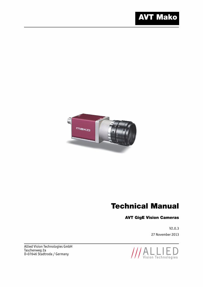
Technical ManualAVT GigE Vision Cameras
V2.0.3
27 November 2013
Allied Vision Technologies GmbHTaschenweg 2aD-07646 Stadtroda / Germany
AVT Mako
Mako Technical Manual V2.0.3
2
Legal noticeFor customers in the U.S.A.This equipment has been tested and found to comply with the limits for a Class B digital device, pursuant to Part 15 of the FCC Rules. These limits are designed to provide reasonable protection against harmful interference when the equipment is operated in a residential environment. This equipment generates, uses, and can radiate radio frequency energy and, if not installed and used in accordance with the instruction manual, may cause harmful interference to radio communica-tions. However there is no guarantee that interferences will not occur in a particular installation. If the equipment does cause harmful interference to radio or television reception, the user is encouraged to try to correct the interference by one or more of the following measures:
• Reorient or relocate the receiving antenna.• Increase the distance between the equipment and the receiver.• Use a different line outlet for the receiver.• Consult a radio or TV technician for help.
You are cautioned that any changes or modifications not expressly approved in this manual could void your authority to operate this equipment. The shielded interface cable recommended in this manual must be used with this equipment in order to comply with the limits for a computing device pursuant to Subpart B of Part 15 of FCC Rules.
For customers in CanadaThis apparatus complies with the Class B limits for radio noise emissions set out in the Radio Interference Regulations.
Pour utilisateurs au CanadaCet appareil est conforme aux normes classe B pour bruits radioélectriques, spécifiées dans le Règlement sur le brouillage radioélectrique.
Life support applicationsThese products are not designed for use in life support appliances, devices, or systems where mal-function of these products can reasonably be expected to result in personal injury. Allied Vision Technologies customers using or selling these products for use in such applications do so at their own risk and agree to fully indemnify Allied Vision Technologies for any damages resulting from such improper use or sale.
TrademarksUnless stated otherwise, all trademarks appearing in this document of Allied Vision Technologies are brands protected by law.
WarrantyThe information provided by Allied Vision Technologies is supplied without any guarantees or warranty whatsoever, be it specific or implicit. Also excluded are all implicit warranties concern-ing the negotiability, the suitability for specific applications or the non-breaking of laws and pat-ents. Even if we assume that the information supplied to us is accurate, errors and inaccuracy may still occur.
CopyrightAll texts, pictures and graphics are protected by copyright and other laws protecting intellectual property. It is not permitted to copy or modify them for trade use or transfer, nor may they be used on websites.
Allied Vision Technologies GmbH 11/2013All rights reserved.Managing Director: Mr. Frank GrubeTax ID: DE 184383113
Headquarters:
Taschenweg 2aD-07646 Stadtroda, GermanyTel.: +49 (0)36428 6770Fax: +49 (0)36428 677-28e-mail: [email protected]
Mako Technical Manual V2.0.3
3
Contents
Contacting Allied Vision Technologies ............................................................... 5
Introduction ................................................................................................................ 6
Document history ................................................................................................................ 6Conventions used in this manual............................................................................................. 7
Styles ........................................................................................................................... 7Symbols ........................................................................................................................ 7
More information ................................................................................................................ 8Before operation ................................................................................................................. 8
Camera cleaning instructions ............................................................................... 9
Warranty ....................................................................................................................... 9Avoiding the necessity of camera cleaning ........................................................................... 9Is it an impurity? – Identifying impurities........................................................................... 10Where is the impurity? – Locating impurities....................................................................... 10Cleaning Instructions..................................................................................................... 11
About Mako GigE cameras ................................................................................... 13
Conformity................................................................................................................. 14
FCC – Class B Device ....................................................................................................... 14
Specifications........................................................................................................... 15
Mako G-032B/C ................................................................................................................. 15Mako G-125B/C ................................................................................................................. 17Mako G-223B/C (NIR) ......................................................................................................... 19Mako G-419B/C (NIR) ......................................................................................................... 21Spectral sensitivity ............................................................................................................ 23
Filter and lenses...................................................................................................... 28
IR cut filter: spectral transmission ........................................................................................ 28Camera lenses................................................................................................................... 28
Mako G-032.................................................................................................................. 29Mako G-125.................................................................................................................. 29Mako G-223.................................................................................................................. 30Mako G-419.................................................................................................................. 30
Camera dimensions................................................................................................ 31
Tripod adapter .................................................................................................................. 31Cross section: C-Mount ....................................................................................................... 32Cross section: CS-Mount...................................................................................................... 33Adjustment of the C-Mount and CS-Mount............................................................................... 34Mako standard housing....................................................................................................... 34
Camera interfaces .................................................................................................. 35
Status LEDs ...................................................................................................................... 35Gigabit Ethernet port ......................................................................................................... 36
Mako Technical Manual V2.0.3
4
Mako I/O connector pin assignment ...................................................................................... 36Mako input description................................................................................................... 37Mako output description ................................................................................................. 38
Control signals.................................................................................................................. 40Inputs......................................................................................................................... 40Input/output pin control ................................................................................................ 40Outputs....................................................................................................................... 40Trigger timing diagram................................................................................................... 42Notes on triggering ....................................................................................................... 42
Description of the data path................................................................................ 44
Mako monochrome cameras................................................................................................. 44Mako with CCD sensors ................................................................................................... 44Mako with CMOS sensors ................................................................................................. 44
Mako color cameras............................................................................................................ 45Mako with CCD sensors ................................................................................................... 45Mako with CMOS sensors ................................................................................................. 45
Camera features ................................................................................................................ 46Frame memory .................................................................................................................. 53
Resolution and ROI frame rates ......................................................................... 54
Mako G-032B/C: ROI frame rates........................................................................................... 55Mako G-125B/C: ROI frame rates........................................................................................... 56Mako G-223B/C: ROI frame rates........................................................................................... 57Mako G-419B/C: ROI frame rates........................................................................................... 58
Appendix .................................................................................................................... 59
Sensor position accuracy of AVT Mako cameras ........................................................................ 59
Index ........................................................................................................................... 60
Mako Technical Manual V2.0.3
5
Contacting Allied Vision Technologies
Contacting Allied Vision Technologies
Info
• Technical information:
http://www.alliedvisiontec.com
• Support:[email protected]
Allied Vision Technologies GmbH (Headquarters)Taschenweg 2a07646 Stadtroda, GermanyTel.: +49 36428-677-0Fax: +49 36428-677-28e-mail: [email protected]
Allied Vision Technologies Canada Inc.101-3750 North Fraser WayBurnaby, BC, V5J 5E9, CanadaTel.: +1 604-875-8855Fax: +1 604-875-8856e-mail: [email protected]
Allied Vision Technologies Inc.38 Washington StreetNewburyport, MA 01950, USAToll Free number +1 877-USA-1394Tel.: +1 978-225-2030Fax: +1 978-225-2029e-mail: [email protected]
Allied Vision Technologies Asia Pte. Ltd.82 Playfair Road#07-02 D’LithiumSingapore 368001Tel.: +65 6634-9027Fax: +65 6634-9029e-mail: [email protected]
Allied Vision Technologies (Shanghai) Co., Ltd.2-2109 Hongwell International Plaza1602# ZhongShanXi RoadShanghai 200235, China Tel.: +86 (21) 64861133Fax: +86 (21) 54233670e-mail: [email protected]
Mako Technical Manual V2.0.3
6
Introduction
Introduction
This Mako Technical Manual describes in depth the technical specifications, dimensions, all pixel formats, bandwidth and frame rate related subjects.
For detailed information on camera features and controls refer to the AVT GigE Camera and Driver Features and AVT GigE Camera and Driver Attributes doc-uments.
Document history
www
AVT Mako literature:http://www.alliedvisiontec.com/us/support/downloads/product-literature/mako.html
Note
We assume that you have already read the AVT GigE Installation Guide and that you have installed the hardware and software on your PC or laptop (Gigabit Ethernet network card, cables). The AVT GigE Installation Guide contains important safety warnings.
http://www.alliedvisiontec.com/emea/support/downloads/product-literature/hardware-installation-guide.html
Version Date Remarks
V2.0.0 2013-Aug-30 New Manual - RELEASE Status
V2.0.1 2013-Sep-11 • Added table of contents• Added Camera cleaning instructions• Updated the specifications for Mako G-223 and G-419• Updated chapter Resolution and ROI frame rates on page 54
V2.0.2 2013-Sep-16 • Updated the frame rate information for Mako G-223 and Mako G-419 in Specifications and Resolution and ROI frame rates chapters
• Updated introduction to include link to Mako literature webpage• Updated Status LEDs section• Added captions to tables in Camera lenses section• Added links to AVT GigE Camera and Driver Features document on page 44
and 46
to be continued on next page
Table 1: Document history
Mako Technical Manual V2.0.3
7
Introduction
Conventions used in this manual
To give this manual an easily understood layout and to emphasize important information, the following typographical styles and symbols are used:
Styles
Symbols
continued from last page
V2.0.3 2013-Nov-27 • Updated gain control values for Mako G-223B/C (NIR) and Mako G-223B/C (NIR)
• Updated Table 12: Status LED (green) on page 35• Updated the note on StreamHoldCapacity in Specifications and Frame mem-
ory sections• Updated block diagrams in chapter Description of the data path on page 44• Updated the Index
Style Function Example
Bold Programs, inputs or highlighting important things boldCourier Code listings etc. InputUpper case Register REGISTERItalics Modes, fields ModeParentheses and/or blue Links (Link)
Table 2: Styles
Note
This symbol highlights important information.
Caution
This symbol highlights important instructions. You have to follow these instructions to avoid malfunctions.
www
This symbol highlights URLs for further information. The URL itself is shown in blue.
Example: http://www.alliedvisiontec.com
Version Date Remarks
Table 1: Document history
Mako Technical Manual V2.0.3
8
Introduction
More information
For more information on hardware and software read the following:• The AVT GigE Installation Guide describes the hardware installation pro-
cedures for AVT GigE cameras and contains important safety instructions.• AVT GigE Camera and Driver Features describes the camera controls of
AVT‘s VIMBA SDK (GenICam) and feature related items.
Before operation
Target group This Technical Manual is the guide to detailed technical information of the camera and is written for experts.
Getting started For a quick guide on how to get started, read the AVT GigE Installation Guide first.
www
To download the AVT GigE Installation Guide and AVT GigE Camera and Driver Features, go to:
http://www.alliedvisiontec.com/emea/support/downloads/product-literature.html
www
Software packages (including documentation and release notes) provided by AVT can be downloaded from:
http://www.alliedvisiontec.com/emea/products/software.html
Caution
Before operating any AVT camera, read the safety instructions and ESD warnings in the AVT GigE Installation Guide.
Caution
Due to the small packaging and high speed of Mako cameras, take special care to maintain a reasonable operating tempera-ture.
If the camera has to be operated in a warm environment:
• Mount the camera on a heat sink such as a metal bracket.• Ensure sufficient air flow.
Mako Technical Manual V2.0.3
9
Camera cleaning instructions
Camera cleaning instructions
This chapter describes safety instructions/cautions valid for Mako cameras in case of cleaning lenses, optical filters/protection glass or sensors.
Warranty
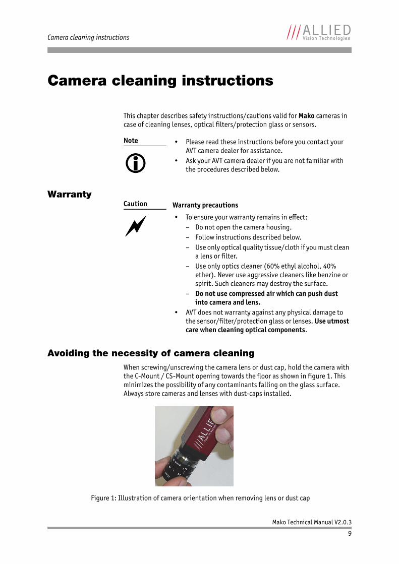
Avoiding the necessity of camera cleaningWhen screwing/unscrewing the camera lens or dust cap, hold the camera with the C-Mount / CS-Mount opening towards the floor as shown in figure 1. This minimizes the possibility of any contaminants falling on the glass surface. Always store cameras and lenses with dust-caps installed.
Note
• Please read these instructions before you contact your
AVT camera dealer for assistance.• Ask your AVT camera dealer if you are not familiar with
the procedures described below.
Caution
Warranty precautions
• To ensure your warranty remains in effect:– Do not open the camera housing.– Follow instructions described below.– Use only optical quality tissue/cloth if you must clean
a lens or filter.– Use only optics cleaner (60% ethyl alcohol, 40%
ether). Never use aggressive cleaners like benzine or spirit. Such cleaners may destroy the surface.
– Do not use compressed air which can push dust into camera and lens.
• AVT does not warranty against any physical damage to the sensor/filter/protection glass or lenses. Use utmost care when cleaning optical components.
Figure 1: Illustration of camera orientation when removing lens or dust cap
Mako Technical Manual V2.0.3
10
Camera cleaning instructions
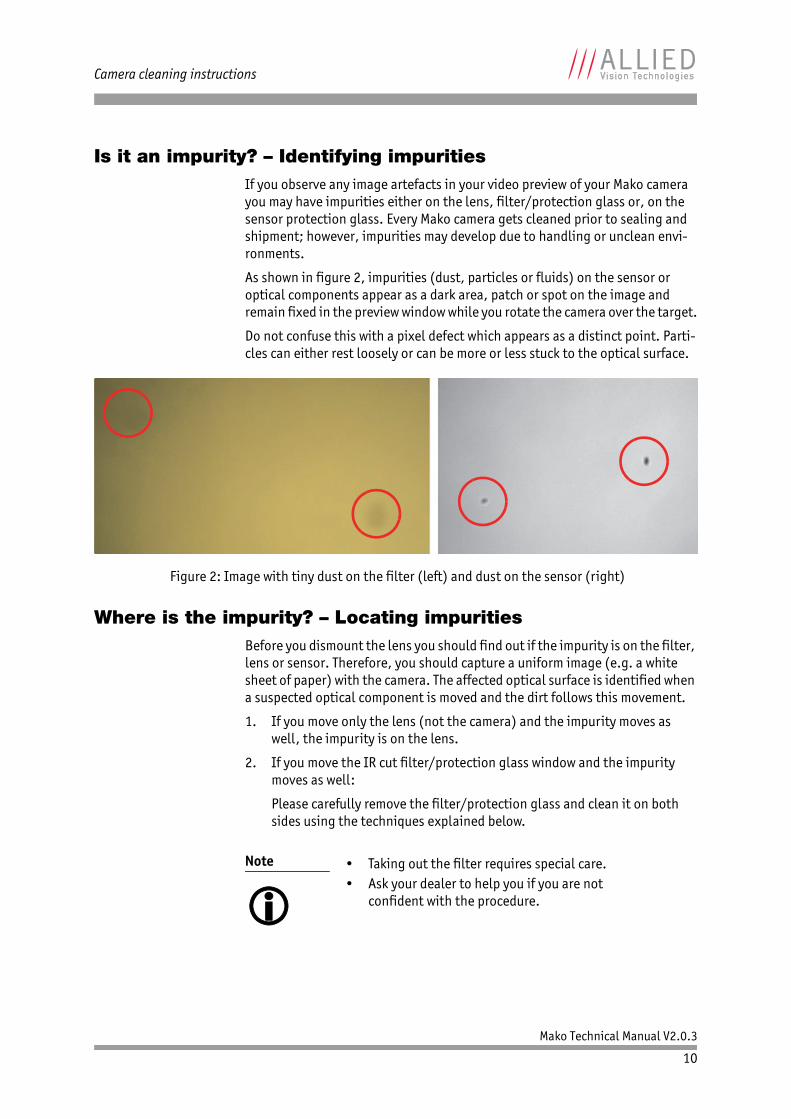
Is it an impurity? – Identifying impuritiesIf you observe any image artefacts in your video preview of your Mako camera you may have impurities either on the lens, filter/protection glass or, on the sensor protection glass. Every Mako camera gets cleaned prior to sealing and shipment; however, impurities may develop due to handling or unclean envi-ronments.
As shown in figure 2, impurities (dust, particles or fluids) on the sensor or optical components appear as a dark area, patch or spot on the image and remain fixed in the preview window while you rotate the camera over the target.
Do not confuse this with a pixel defect which appears as a distinct point. Parti-cles can either rest loosely or can be more or less stuck to the optical surface.
Where is the impurity? – Locating impuritiesBefore you dismount the lens you should find out if the impurity is on the filter, lens or sensor. Therefore, you should capture a uniform image (e.g. a white sheet of paper) with the camera. The affected optical surface is identified when a suspected optical component is moved and the dirt follows this movement.
1. If you move only the lens (not the camera) and the impurity moves as well, the impurity is on the lens.
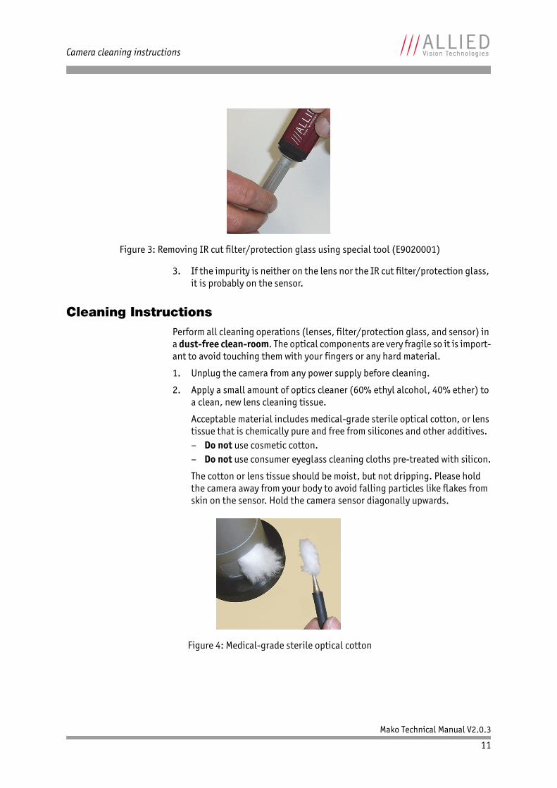
2. If you move the IR cut filter/protection glass window and the impurity moves as well:
Please carefully remove the filter/protection glass and clean it on both sides using the techniques explained below.
Figure 2: Image with tiny dust on the filter (left) and dust on the sensor (right)
Note
• Taking out the filter requires special care.• Ask your dealer to help you if you are not
confident with the procedure.
Mako Technical Manual V2.0.3
11
Camera cleaning instructions
3. If the impurity is neither on the lens nor the IR cut filter/protection glass, it is probably on the sensor.
Cleaning InstructionsPerform all cleaning operations (lenses, filter/protection glass, and sensor) in a dust-free clean-room. The optical components are very fragile so it is import-ant to avoid touching them with your fingers or any hard material.
1. Unplug the camera from any power supply before cleaning.
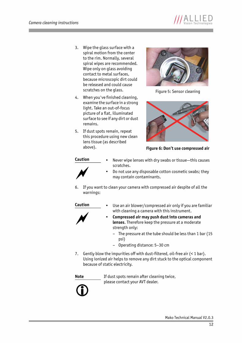
2. Apply a small amount of optics cleaner (60% ethyl alcohol, 40% ether) to a clean, new lens cleaning tissue.
Acceptable material includes medical-grade sterile optical cotton, or lens tissue that is chemically pure and free from silicones and other additives.– Do not use cosmetic cotton.– Do not use consumer eyeglass cleaning cloths pre-treated with silicon.
The cotton or lens tissue should be moist, but not dripping. Please hold the camera away from your body to avoid falling particles like flakes from skin on the sensor. Hold the camera sensor diagonally upwards.
Figure 3: Removing IR cut filter/protection glass using special tool (E9020001)
Figure 4: Medical-grade sterile optical cotton
Mako Technical Manual V2.0.3
12
Camera cleaning instructions
3. Wipe the glass surface with a spiral motion from the center to the rim. Normally, several spiral wipes are recommended. Wipe only on glass avoiding contact to metal surfaces, because microscopic dirt could be released and could cause scratches on the glass.
4. When you've finished cleaning, examine the surface in a strong light. Take an out-of-focus picture of a flat, illuminated surface to see if any dirt or dust remains.
5. If dust spots remain, repeat this procedure using new clean lens tissue (as described above).
6. If you want to clean your camera with compressed air despite of all the warnings:
7. Gently blow the impurities off with dust-filtered, oil-free air (< 1 bar). Using ionized air helps to remove any dirt stuck to the optical component because of static electricity.
Caution
• Never wipe lenses with dry swabs or tissue—this causes
scratches.• Do not use any disposable cotton cosmetic swabs; they
may contain contaminants.
Caution
• Use an air blower/compressed air only if you are familiar
with cleaning a camera with this instrument.• Compressed air may push dust into cameras and
lenses. Therefore keep the pressure at a moderate strength only:– The pressure at the tube should be less than 1 bar (15
psi)– Operating distance: 5–30 cm
Note
If dust spots remain after cleaning twice, please contact your AVT dealer.
Figure 5: Sensor cleaning
Figure 6: Don’t use compressed air
Mako Technical Manual V2.0.3
13
About Mako GigE cameras
About Mako GigE cameras
Mako Mako cameras have a Gigabit Ethernet interface.
GigE GigE is the abbreviation for Gigabit Ethernet.
All AVT Mako cameras are GigE Vision V1.2 compliant cameras with Gigabit Ethernet interface. AVT Mako cameras work with Gigabit Ethernet hardware and cable lengths up to 100 m.
GigE Vision The GigE Vision standard is an interface standard for digital machine vision cam-eras widely supported in the industrial imaging industry. In contrast, GigE (Gigabit Ethernet) is the network GigE Vision is built upon.
GenICam GenICam is the command structure for the GigE Vision camera controls. GenICam is administered by the European Machine Vision Association (EMVA). GenICam establishes a common camera control interface allowing third-party software to communicate with cameras from various manufacturers without customization. AVT GigE cameras are GenICam V1.0 compliant.
Mako Technical Manual V2.0.3
14
Conformity
ConformityAllied Vision Technologies declares under its sole responsibility that all stan-dard cameras of the AVT Mako family to which this declaration relates are in con-formity with the following standard(s) or other normative document(s):• CE, following the provisions of 2004/108/EG directive• FCC Part 15 Class B• RoHS (2011/65/EU)• CE• WEEE
We declare, under our sole responsibility, that the previously described AVT Mako cameras conform to the directives of the CE.
FCC – Class B DeviceNote: This equipment has been tested and found to comply with the limits for a Class B digital device, pursuant to part 15 of the FCC Rules. These limits are designed to provide reasonable protection against harmful interference in a residential environment. This device complies with part 15 of the FCC Rules. Operation is subject to the following two conditions: (1) This device may not cause harmful interference, and (2) this device must accept any interference received, including interference that may cause undesired operation. This equipment generates, uses, and can radiate radio frequency energy and, if not installed and used in accordance with the instructions, may cause harmful interference to radio communications. Operation of this equipment in a resi-dential area is likely to cause harmful interference in which case the user will be required to correct the interference at his own expense. You are cautioned that any changes or modifications not expressly approved in this manual could void your authority to operate this equipment.
Mako Technical Manual V2.0.3
15
Specifications
Specifications
Mako G-032B/C
Caution
Before operating any AVT camera, read the safety instructions and ESD warnings in the AVT GigE Installation Guide.
http://www.alliedvisiontec.com/emea/support/downloads/product-literature/hardware-installation-guide.html
Caution
Due to the small packaging and high speed of Mako cameras, take special care to maintain a reasonable operating tempera-ture.
If the camera has to be operated in a warm environment:
• Mount the camera on a heat sink such as a metal bracket.• Ensure sufficient air flow.
Feature Specification
Sensor Type 1/3 (diag. 6 mm) progressive scan SONY IT CCD ICX424AL/AQ with HAD microlens
Effective chip size 4.9 mm x 3.6 mm
Cell size 7.4 μm x 7.4 μm
Resolution (maximum) 658 x 492 pixels
Lens mount C-Mount: 17.526 mm (in air); Ø 25.4 mm (32 tpi)Maximum protrusion: 9.8 mm (see figure 18)
CS-Mount: 12.526 mm (in air); Ø 25.4 mm (32 tpi)Maximum protrusion: 4.8 mm (see figure 20)
ADC 14 bits
Pixel format Only monochrome: Mono8, Mono12Packed, Mono12Only color: BayerRG8, BayerRG12, BayerRG12Packed, Mono8, RGB8Packed, YUV411Packed, YUV422Packet, YUV444Packed, BGR8Packed
Frame rates Up to 102 fps
Gain control Manual: 0–30 dB (1 dB/step); auto gain (select. ROI)
Exposure time 10 μs to 93 s; auto shutter (select. ROI)
External trigger event Rising edge, falling edge, any edge, level high, level low
Table 3: Specification Mako G-032B/C
Note
Maximum protrusion means the distance from lens flange to the glass filter in the camera.
Mako Technical Manual V2.0.3
16
Specifications
External trigger delay 0 to 46 s in 1 μs increments
Fixed rate control 0.011 fps to maximum frame rate (steps of 0.001 fps)
Imaging modes Free-running, external trigger, fixed rate, software trigger
Sync Out modes Trigger ready, trigger input, exposing, readout, imaging, strobe, GPO
Internal image memory 64 MByte, up to 202 frames
Smart functions Auto gain control, auto exposure control, 64 MByte image memory, binning (monochrome binning, also for color cameras; but no color binning), LUT, gamma, config files (user sets)Only color: auto white balance, hue, saturation
I/O One configurable optocoupled inputThree configurable optocoupled outputs
Digital interface IEEE 802.3 1000BASE-T (GigE Vision V1.2)
Camera control interface GenICam V1.0 compliant
Power requirements DC 12–24 V ±10% via 8-pin HIROSE, or PoE (compliant with Power over Ethernet IEEE 802.3at/af)
Power consumption With PoE: typical 2.8 WWithout PoE: 2.4 W (@ 12 V DC)(maximal frame rate at full resolution)
Dimensions (L x W x H) 60.5 x 29 x 29 mm; including connectors, without tripod and lens
Mass 80 g (without lens)
Operating temperature + 5 °C to + 45 °C ambient temperature (without condensation)
Storage temperature - 10 °C to + 70 °C ambient temperature (without condensation)
Regulations CE, FCC Class B, RoHS (2011/65/EU), WEEE
Standard accessories Color: IR cut filter
Optional accessories Monochrome: IR cut filter, IR pass filter, protection glassColor: protection glassTripod adapter (order number 4807)
On request Gigabit Ethernet network card, Gigabit Ethernet network cables
Software packages Free of charge, see http://www.alliedvisiontec.com/html
Feature Specification
Table 3: Specification Mako G-032B/C
Note
The number of frames (StreamHoldCapacity) depends on resolution, pixel format, and GVSP packet size. Stated number of frames is typical for full resolution, Mono8/Bayer8, and GevSCPSPacketSize = 8192.
Mako Technical Manual V2.0.3
17
Specifications
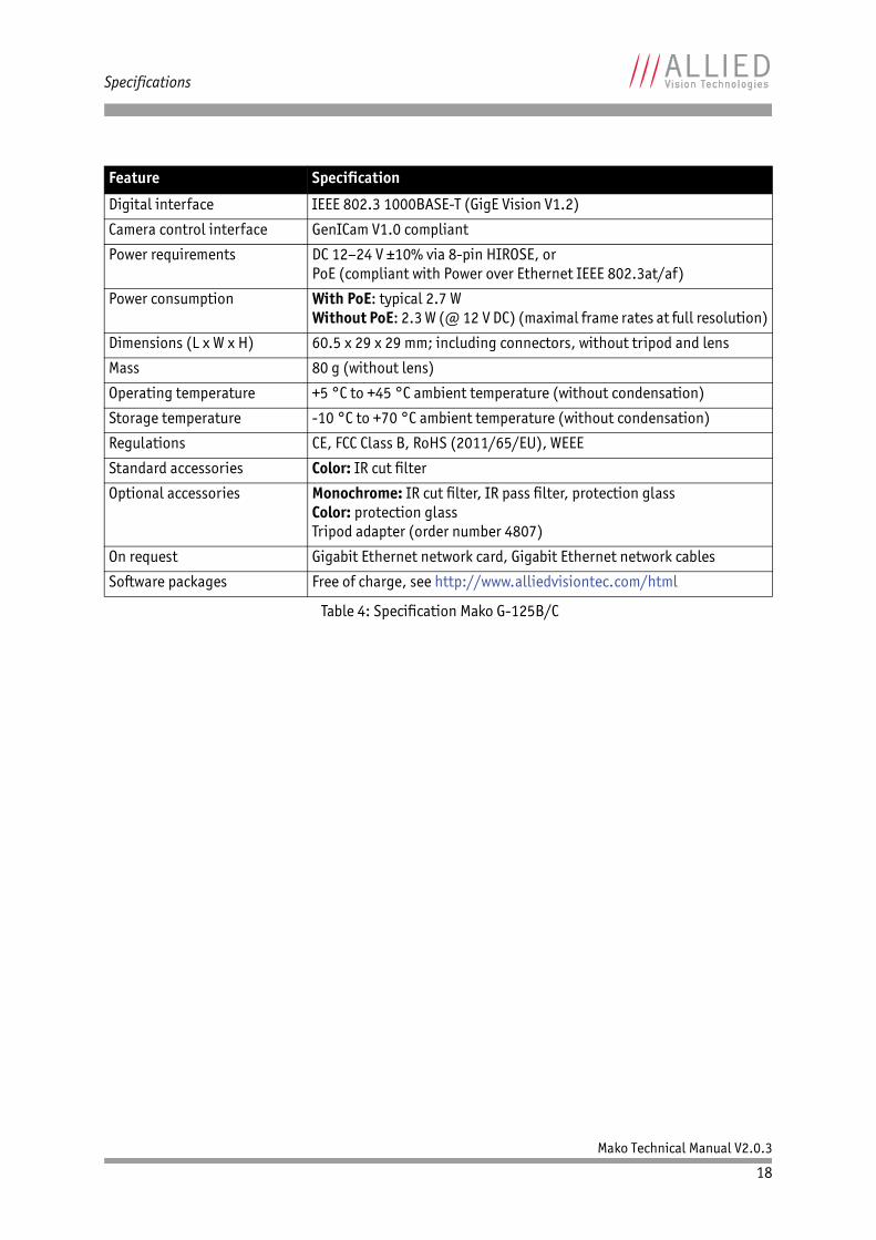
Mako G-125B/C
Feature Specification
Sensor Type 1/3 (diag. 6 mm) progressive scan SONY IT CCD ICX445ALA/AQA with EXview HAD microlens
Effective chip size 4.8 mm x 3.6 mm
Cell size 3.75 μm x 3.75 μm
Resolution (maximum) 1292 x 964 pixels
Lens mount C-Mount: 17.526 mm (in air); Ø 25.4 mm (32 tpi)Maximum protrusion: 9.8 mm (see figure 18)
CS-Mount: 12.526 mm (in air); Ø 25.4 mm (32 tpi)Maximum protrusion: 4.8 mm (see figure 20)
ADC 14 bits
Pixel format Only monochrome: Mono8, Mono12Packed, Mono12Only color: BayerRG8, BayerRG12, BayerRG12Packed, Mono8, RGB8Packed, YUV411Packed, YUV422Packet, YUV444Packed, BGR8Packed
Frame rates Up to 30 fps
Gain control Manual: 0–30 dB (1 dB/step); auto gain (select. ROI)
Exposure time 12 μs to 84 s; auto shutter (select. ROI)
External trigger event Rising edge, falling edge, any edge, level high, level low
External trigger delay 0 to 42 s in 1 μs increments
Fixed rate control 0.012 fps to maximum frame rate (steps of 0.001 fps)
Imaging modes Free-running, external trigger, fixed rate, software trigger
Sync Out modes Trigger ready, trigger input, exposing, readout, imaging, strobe, GPO
Internal image memory 64 MByte, up to 52 frames
Smart functions Auto gain control, auto exposure control, 64 MByte image memory, binning (monochrome binning, also for color cameras; but no color binning), LUT, gamma, config files (user sets)Only color: auto white balance, hue, saturation
I/O One configurable optocoupled inputThree configurable optocoupled outputs
Table 4: Specification Mako G-125B/C
Note
Maximum protrusion means the distance from lens flange to the glass filter in the camera.
Note
The number of frames (StreamHoldCapacity) depends on resolution, pixel format, and GVSP packet size. Stated number of frames is typical for full resolution, Mono8/Bayer8, and GevSCPSPacketSize = 8192.
Mako Technical Manual V2.0.3
18
Specifications
Digital interface IEEE 802.3 1000BASE-T (GigE Vision V1.2)
Camera control interface GenICam V1.0 compliant
Power requirements DC 12–24 V ±10% via 8-pin HIROSE, or PoE (compliant with Power over Ethernet IEEE 802.3at/af)
Power consumption With PoE: typical 2.7 WWithout PoE: 2.3 W (@ 12 V DC) (maximal frame rates at full resolution)
Dimensions (L x W x H) 60.5 x 29 x 29 mm; including connectors, without tripod and lens
Mass 80 g (without lens)
Operating temperature +5 °C to +45 °C ambient temperature (without condensation)
Storage temperature -10 °C to +70 °C ambient temperature (without condensation)
Regulations CE, FCC Class B, RoHS (2011/65/EU), WEEE
Standard accessories Color: IR cut filter
Optional accessories Monochrome: IR cut filter, IR pass filter, protection glassColor: protection glassTripod adapter (order number 4807)
On request Gigabit Ethernet network card, Gigabit Ethernet network cables
Software packages Free of charge, see http://www.alliedvisiontec.com/html
Feature Specification
Table 4: Specification Mako G-125B/C

Mako Technical Manual V2.0.3
19
Specifications
Mako G-223B/C (NIR)
Feature Specification
Sensor Type 2/3 (diag. 8 mm, 1 inch lens recommended) CMOS sensor: CMOSIS CMV2000 (monochrome/color) with microlenses and global shutter
The monochrome version is also available as NIR enhanced variant (Mako G-223B NIR). Except for the sensor response, the technical data of the NIR enhanced variant are identical with Mako G-223B.
Effective chip size 11.26 mm x 5.98 mm
Cell size 5.5 μm x 5.5 μm
Resolution (maximum) 2048 x 1088 pixels
Lens mount C-Mount: 17.526 mm (in air); Ø 25.4 mm (32 tpi)Maximum protrusion: 10.8 mm (see figure 19)
CS-Mount: 12.526 mm (in air); Ø 25.4 mm (32 tpi)Maximum protrusion: 5.8 mm (see figure 21)
ADC 12 bits
Pixel format Only monochrome: Mono8, Mono12Packed, Mono12Only color: BayerRG8, BayerRG12, BayerRG12Packed, Mono8, RGB8Packed, YUV411Packed, YUV422Packet, YUV444Packed, BGR8Packed
Frame rates Up to 49.5 fps
Gain control Manual: 0–26 dB (1 dB/step); auto gain (select. ROI)
Exposure time 21 μs to 153 s; auto shutter (select. ROI)
External trigger event Rising edge, falling edge, any edge, level high, level low
External trigger delay 0 to 306 s in 1 μs increments
Fixed rate control 0.01 fps to 49.52 fps (steps of 0.1 fps)
Imaging modes Free-running, external trigger, fixed rate, software trigger
Sync Out modes Trigger ready, trigger input, exposing, readout, imaging, strobe, GPO
Internal image memory 64 MByte, up to 29 frames
Smart functions Auto gain control, auto exposure control, 64MByte image memory, no binning, LUT, gamma, config files (user sets)Only color: auto white balance, hue, saturation
Table 5: Specification Mako G-223B/C
Note
Maximum protrusion means the distance from lens flange to the glass filter in the camera.
Note
The number of frames (StreamHoldCapacity) depends on resolution, pixel format, and GVSP packet size. Stated number of frames is typical for full resolution, Mono8/Bayer8, and GevSCPSPacketSize = 8192.

Mako Technical Manual V2.0.3
20
Specifications
I/O One configurable optocoupled inputThree configurable optocoupled outputs
Digital interface IEEE 802.3 1000BASE-T (GigE Vision V1.2)
Camera control interface GenICam V1.0 compliant
Power requirements DC 12–24 V ±10% via 8-pin HIROSE, orPoE (compliant with Power over Ethernet IEEE 802.3at/af)
Power consumption With PoE: typical 2.8 WWithout PoE: 2.4 W (@ 12 V DC) (maximal frame rates at full resolution)
Dimensions (L x W x H) 60.5 x 29 x 29 mm; including connectors, without tripod and lens
Mass 80 g (without lens)
Operating temperature +5 °C to +45 °C ambient temperature (without condensation)
Storage temperature -10 °C to +70 °C ambient temperature (without condensation)
Regulations CE, FCC Class B, RoHS (2011/65/EU), WEEE
Standard accessories Color: IR cut filter
Optional accessories Monochrome: IR cut filter, IR pass filter, protection glassColor: protection glassTripod adapter (order number 4807)
On request Gigabit Ethernet network card, Gigabit Ethernet network cables
Software packages Free of charge, see http://www.alliedvisiontec.com/html
Feature Specification
Table 5: Specification Mako G-223B/C
Mako Technical Manual V2.0.3
21
Specifications
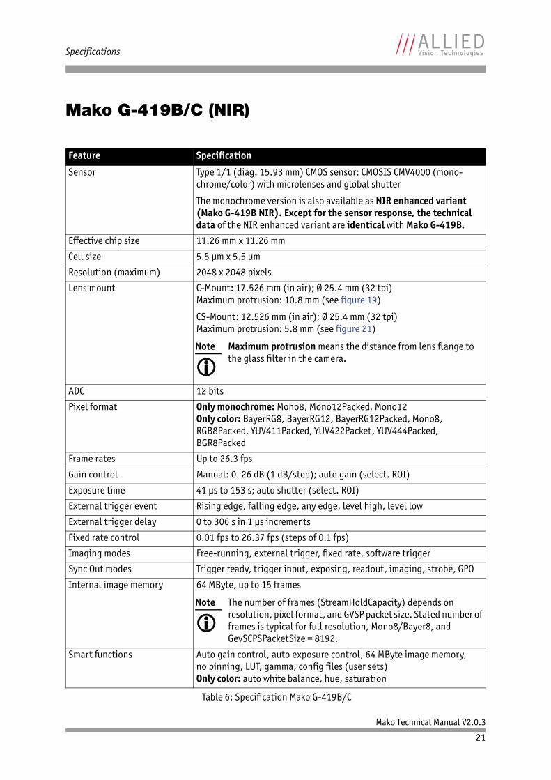
Mako G-419B/C (NIR)
Feature Specification
Sensor Type 1/1 (diag. 15.93 mm) CMOS sensor: CMOSIS CMV4000 (mono-chrome/color) with microlenses and global shutter
The monochrome version is also available as NIR enhanced variant (Mako G-419B NIR). Except for the sensor response, the technical data of the NIR enhanced variant are identical with Mako G-419B.
Effective chip size 11.26 mm x 11.26 mm
Cell size 5.5 μm x 5.5 μm
Resolution (maximum) 2048 x 2048 pixels
Lens mount C-Mount: 17.526 mm (in air); Ø 25.4 mm (32 tpi)Maximum protrusion: 10.8 mm (see figure 19)
CS-Mount: 12.526 mm (in air); Ø 25.4 mm (32 tpi)Maximum protrusion: 5.8 mm (see figure 21)
ADC 12 bits
Pixel format Only monochrome: Mono8, Mono12Packed, Mono12Only color: BayerRG8, BayerRG12, BayerRG12Packed, Mono8, RGB8Packed, YUV411Packed, YUV422Packet, YUV444Packed, BGR8Packed
Frame rates Up to 26.3 fps
Gain control Manual: 0–26 dB (1 dB/step); auto gain (select. ROI)
Exposure time 41 μs to 153 s; auto shutter (select. ROI)
External trigger event Rising edge, falling edge, any edge, level high, level low
External trigger delay 0 to 306 s in 1 μs increments
Fixed rate control 0.01 fps to 26.37 fps (steps of 0.1 fps)
Imaging modes Free-running, external trigger, fixed rate, software trigger
Sync Out modes Trigger ready, trigger input, exposing, readout, imaging, strobe, GPO
Internal image memory 64 MByte, up to 15 frames
Smart functions Auto gain control, auto exposure control, 64 MByte image memory, no binning, LUT, gamma, config files (user sets)Only color: auto white balance, hue, saturation
Table 6: Specification Mako G-419B/C
Note
Maximum protrusion means the distance from lens flange to the glass filter in the camera.
Note
The number of frames (StreamHoldCapacity) depends on resolution, pixel format, and GVSP packet size. Stated number of frames is typical for full resolution, Mono8/Bayer8, and GevSCPSPacketSize = 8192.
Mako Technical Manual V2.0.3
22
Specifications
I/O One configurable optocoupled inputThree configurable optocoupled outputs
Digital interface IEEE 802.3 1000BASE-T (GigE Vision V1.2)
Camera control interface GenICam V1.0 compliant
Power requirements DC 12–24 V ±10% via 8-pin HIROSE, orPoE (compliant with Power over Ethernet IEEE 802.3at/af)
Power consumption With PoE: typical 2.7 WWithout PoE: 2.3 W (@ 12 V DC) (maximal frame rates at full resolution)
Dimensions (L x W x H) 60.5 x 29 x 29 mm; including connectors, without tripod and lens
Mass 80 g (without lens)
Operating temperature +5 °C to +45 °C ambient temperature (without condensation)
Storage temperature -10 °C to +70 °C ambient temperature (without condensation)
Regulations CE, FCC Class B, RoHS (2011/65/EU), WEEE
Standard accessories Color: IR cut filter
Optional accessories Monochrome: IR cut filter, IR pass filter, protection glassColor: protection glassTripod adapter (order number 4807)
On request Gigabit Ethernet network card, Gigabit Ethernet network cables
Software packages Free of charge, see http://www.alliedvisiontec.com/html
Feature Specification
Table 6: Specification Mako G-419B/C
Mako Technical Manual V2.0.3
23
Specifications
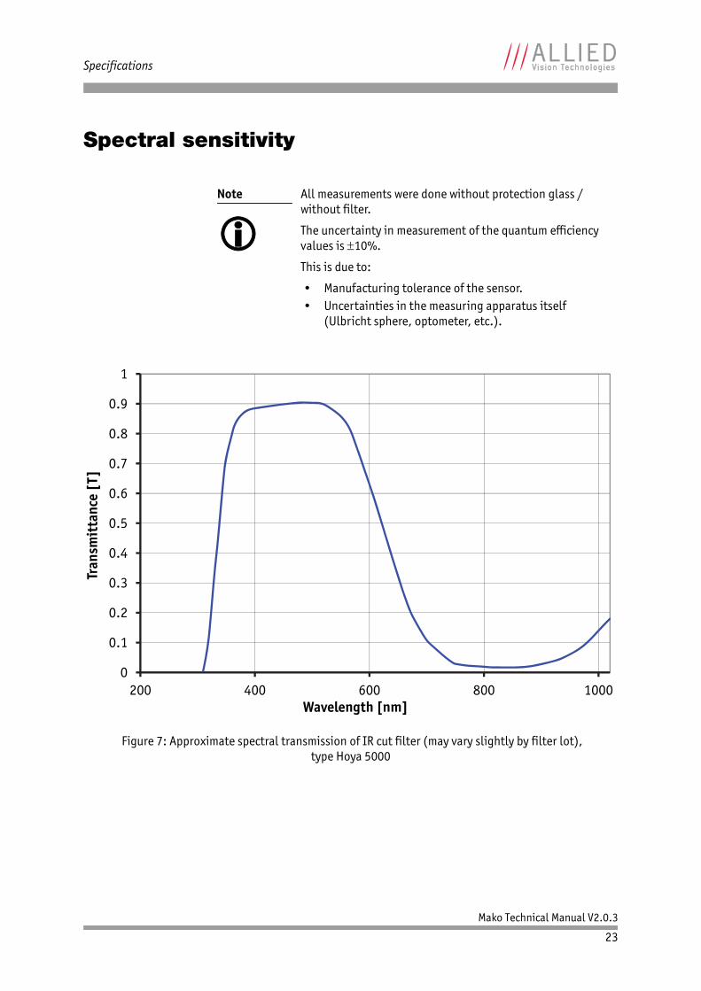
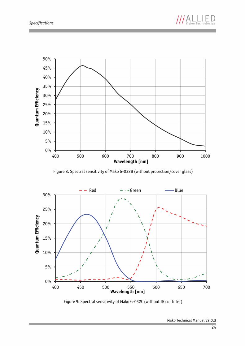
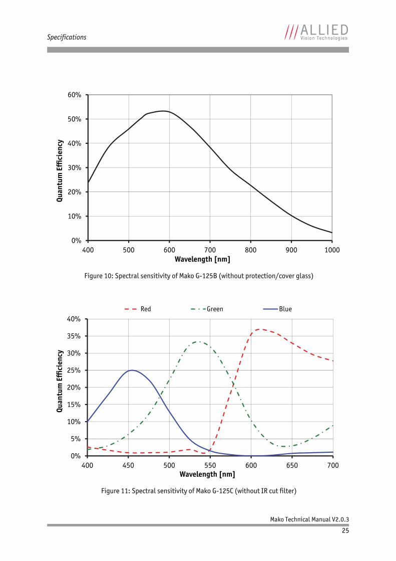
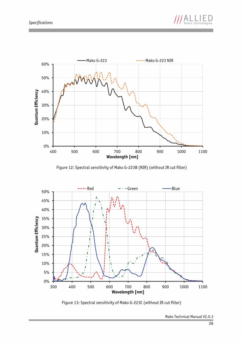
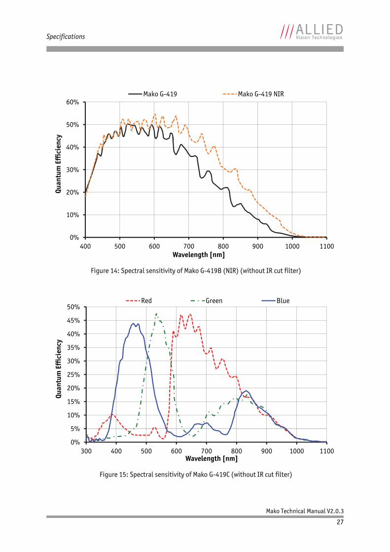
Spectral sensitivity
Note
All measurements were done without protection glass / without filter.
The uncertainty in measurement of the quantum efficiency values is 10%.
This is due to:
• Manufacturing tolerance of the sensor.• Uncertainties in the measuring apparatus itself
(Ulbricht sphere, optometer, etc.).
Figure 7: Approximate spectral transmission of IR cut filter (may vary slightly by filter lot),type Hoya 5000
0
0.1
0.2
0.3
0.4
0.5
0.6
0.7
0.8
0.9
1
200 400 600 800 1000
Tran
smit
tanc
e [T
]
Wavelength [nm]
Mako Technical Manual V2.0.3
24
Specifications
Figure 8: Spectral sensitivity of Mako G-032B (without protection/cover glass)
Figure 9: Spectral sensitivity of Mako G-032C (without IR cut filter)
0%
5%
10%
15%
20%
25%
30%
35%
40%
45%
50%
400 500 600 700 800 900 1000
Quan
tum
Eff
icie
ncy
Wavelength [nm]
0%
5%
10%
15%
20%
25%
30%
400 450 500 550 600 650 700
Quan
tum
Eff
icie
ncy
Wavelength [nm]
Red Green Blue
Mako Technical Manual V2.0.3
25
Specifications
Figure 10: Spectral sensitivity of Mako G-125B (without protection/cover glass)
Figure 11: Spectral sensitivity of Mako G-125C (without IR cut filter)
0%
10%
20%
30%
40%
50%
60%
400 500 600 700 800 900 1000
Quan
tum
Eff
icie
ncy
Wavelength [nm]
0%
5%
10%
15%
20%
25%
30%
35%
40%
400 450 500 550 600 650 700
Quan
tum
Eff
icie
ncy
Wavelength [nm]
Red Green Blue
Mako Technical Manual V2.0.3
26
Specifications
Figure 12: Spectral sensitivity of Mako G-223B (NIR) (without IR cut filter)
Figure 13: Spectral sensitivity of Mako G-223C (without IR cut filter)
0%
10%
20%
30%
40%
50%
60%
400 500 600 700 800 900 1000 1100
Quan
tum
Eff
icie
ncy
Wavelength [nm]
Mako G-223 Mako G-223 NIR
0%
5%
10%
15%
20%
25%
30%
35%
40%
45%
50%
300 400 500 600 700 800 900 1000 1100
Quan
tum
Eff
icie
ncy
Wavelength [nm]
Red Green Blue
Mako Technical Manual V2.0.3
27
Specifications
Figure 14: Spectral sensitivity of Mako G-419B (NIR) (without IR cut filter)
Figure 15: Spectral sensitivity of Mako G-419C (without IR cut filter)
0%
10%
20%
30%
40%
50%
60%
400 500 600 700 800 900 1000 1100
Quan
tum
Eff
icie
ncy
Wavelength [nm]
Mako G-419 Mako G-419 NIR
0%
5%
10%
15%
20%
25%
30%
35%
40%
45%
50%
300 400 500 600 700 800 900 1000 1100
Quan
tum
Eff
icie
ncy
Wavelength [nm]
Red Green Blue
Mako Technical Manual V2.0.3
28
Filter and lenses
Filter and lenses
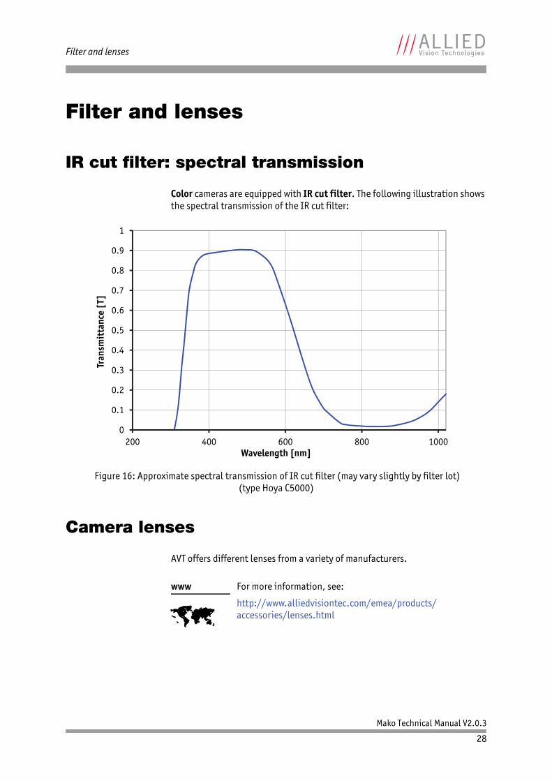
IR cut filter: spectral transmission
Color cameras are equipped with IR cut filter. The following illustration shows the spectral transmission of the IR cut filter:
Camera lenses
AVT offers different lenses from a variety of manufacturers.
Figure 16: Approximate spectral transmission of IR cut filter (may vary slightly by filter lot)(type Hoya C5000)
www
For more information, see:
http://www.alliedvisiontec.com/emea/products/accessories/lenses.html
0
0.1
0.2
0.3
0.4
0.5
0.6
0.7
0.8
0.9
1
200 400 600 800 1000
Tran
smit
tanc
e [T
]
Wavelength [nm]
Mako Technical Manual V2.0.3
29
Filter and lenses
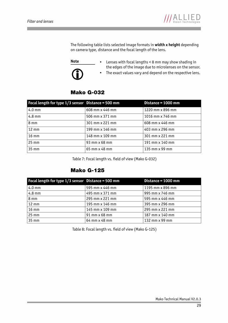
The following table lists selected image formats in width x height depending on camera type, distance and the focal length of the lens.
Mako G-032
Mako G-125
Note
• Lenses with focal lengths < 8 mm may show shading in
the edges of the image due to microlenses on the sensor.• The exact values vary and depend on the respective lens.
Focal length for type 1/3 sensor Distance = 500 mm Distance = 1000 mm
4.0 mm 608 mm x 446 mm 1220 mm x 896 mm
4.8 mm 506 mm x 371 mm 1016 mm x 746 mm
8 mm 301 mm x 221 mm 608 mm x 446 mm
12 mm 199 mm x 146 mm 403 mm x 296 mm
16 mm 148 mm x 109 mm 301 mm x 221 mm
25 mm 93 mm x 68 mm 191 mm x 140 mm
35 mm 65 mm x 48 mm 135 mm x 99 mm
Table 7: Focal length vs. field of view (Mako G-032)
Focal length for type 1/3 sensor Distance = 500 mm Distance = 1000 mm
4.0 mm 595 mm x 446 mm 1195 mm x 896 mm4.8 mm 495 mm x 371 mm 995 mm x 746 mm8 mm 295 mm x 221 mm 595 mm x 446 mm12 mm 195 mm x 146 mm 395 mm x 296 mm16 mm 145 mm x 109 mm 295 mm x 221 mm25 mm 91 mm x 68 mm 187 mm x 140 mm35 mm 64 mm x 48 mm 132 mm x 99 mm
Table 8: Focal length vs. field of view (Mako G-125)
Mako Technical Manual V2.0.3
30
Filter and lenses
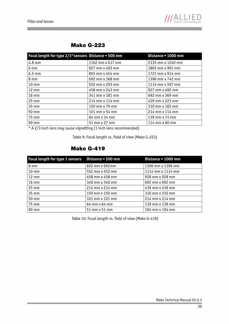
Mako G-223
Mako G-419
Focal length for type 2/3*sensors Distance = 500 mm Distance = 1000 mm
4.8 mm 1162 mm x 617 mm 2335 mm x 1240 mm6 mm 927 mm x 492 mm 1865 mm x 991 mm6.5 mm 855 mm x 454 mm 1721 mm x 914 mm8 mm 692 mm x 368 mm 1396 mm x 742 mm10 mm 552 mm x 293 mm 1114 mm x 597 mm12 mm 458 mm x 243 mm 927 mm x 492 mm16 mm 341 mm x 181 mm 692 mm x 369 mm25 mm 214 mm x 114 mm 439 mm x 223 mm35 mm 150 mm x 79 mm 310 mm x 165 mm50 mm 101 mm x 54 mm 214 mm x 114 mm75 mm 64 mm x 34 mm 139 mm x 74 mm90 mm 51 mm x 27 mm 114 mm x 60 mm* A 2/3 inch lens may cause vignetting (1 inch lens recommended)
Table 9: Focal length vs. field of view (Mako G-223)
Focal length for type 1 sensors Distance = 500 mm Distance = 1000 mm
8 mm 692 mm x 692mm 1396 mm x 1396 mm10 mm 552 mm x 552 mm 1114 mm x 1114 mm12 mm 458 mm x 458 mm 928 mm x 928 mm16 mm 340 mm x 340 mm 692 mm x 692 mm25 mm 214 mm x 214 mm 439 mm x 439 mm35 mm 150 mm x 150 mm 310 mm x 310 mm50 mm 101 mm x 101 mm 214 mm x 214 mm75 mm 64 mm x 64 mm 139 mm x 139 mm90 mm 51 mm x 51 mm 104 mm x 104 mm
Table 10: Focal length vs. field of view (Mako G-419)
Mako Technical Manual V2.0.3
31
Camera dimensions
Camera dimensions
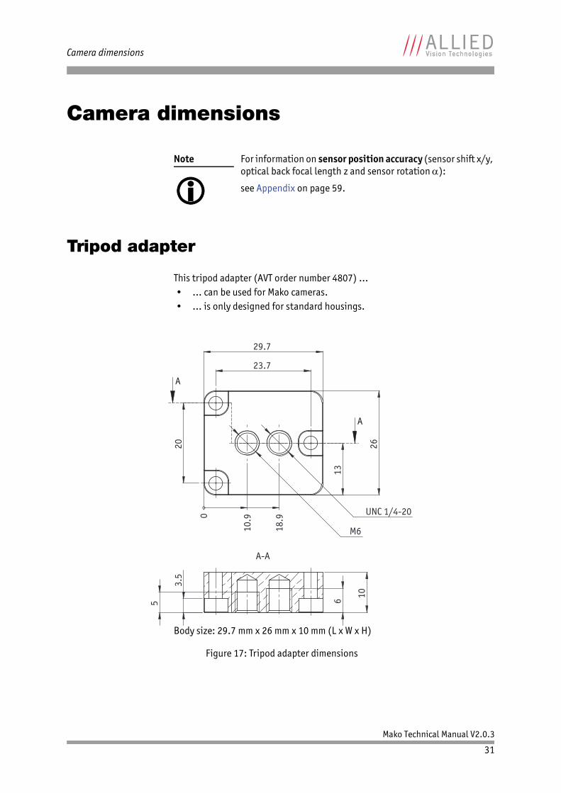
Tripod adapter
This tripod adapter (AVT order number 4807) ...• ... can be used for Mako cameras.• ... is only designed for standard housings.
Note
For information on sensor position accuracy (sensor shift x/y, optical back focal length z and sensor rotation ):
see Appendix on page 59.
Body size: 29.7 mm x 26 mm x 10 mm (L x W x H)
Figure 17: Tripod adapter dimensions
29.7
26
13
20
23.7
UNC 1/4-20
M6
0
10.
9
18.
9
A
A
10 3
.5
5 6
A-A
Mako Technical Manual V2.0.3
32
Camera dimensions
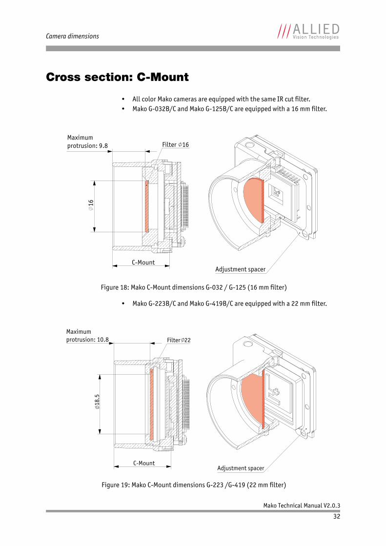
Cross section: C-Mount
• All color Mako cameras are equipped with the same IR cut filter.• Mako G-032B/C and Mako G-125B/C are equipped with a 16 mm filter.
• Mako G-223B/C and Mako G-419B/C are equipped with a 22 mm filter.
Figure 18: Mako C-Mount dimensions G-032 / G-125 (16 mm filter)
Figure 19: Mako C-Mount dimensions G-223 /G-419 (22 mm filter)
Filter 16Maximumprotrusion: 9.8
C-Mount
16
Adjustment spacer
Adjustment spacer
Filter 22
18.5
Maximumprotrusion: 10.8
C-Mount
Mako Technical Manual V2.0.3
33
Camera dimensions
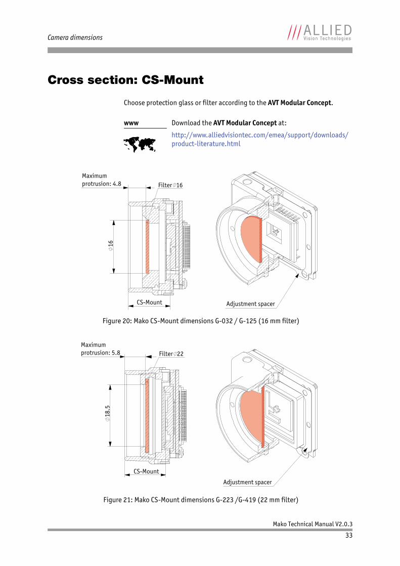
Cross section: CS-Mount
Choose protection glass or filter according to the AVT Modular Concept.
www
Download the AVT Modular Concept at:
http://www.alliedvisiontec.com/emea/support/downloads/product-literature.html
Figure 20: Mako CS-Mount dimensions G-032 / G-125 (16 mm filter)
Figure 21: Mako CS-Mount dimensions G-223 /G-419 (22 mm filter)
Adjustment spacer
Filter 16
CS-Mount
Maximumprotrusion: 4.8
16
Adjustment spacer
Filter 22
18.5
Maximumprotrusion: 5.8
CS-Mount
Mako Technical Manual V2.0.3
34
Camera dimensions
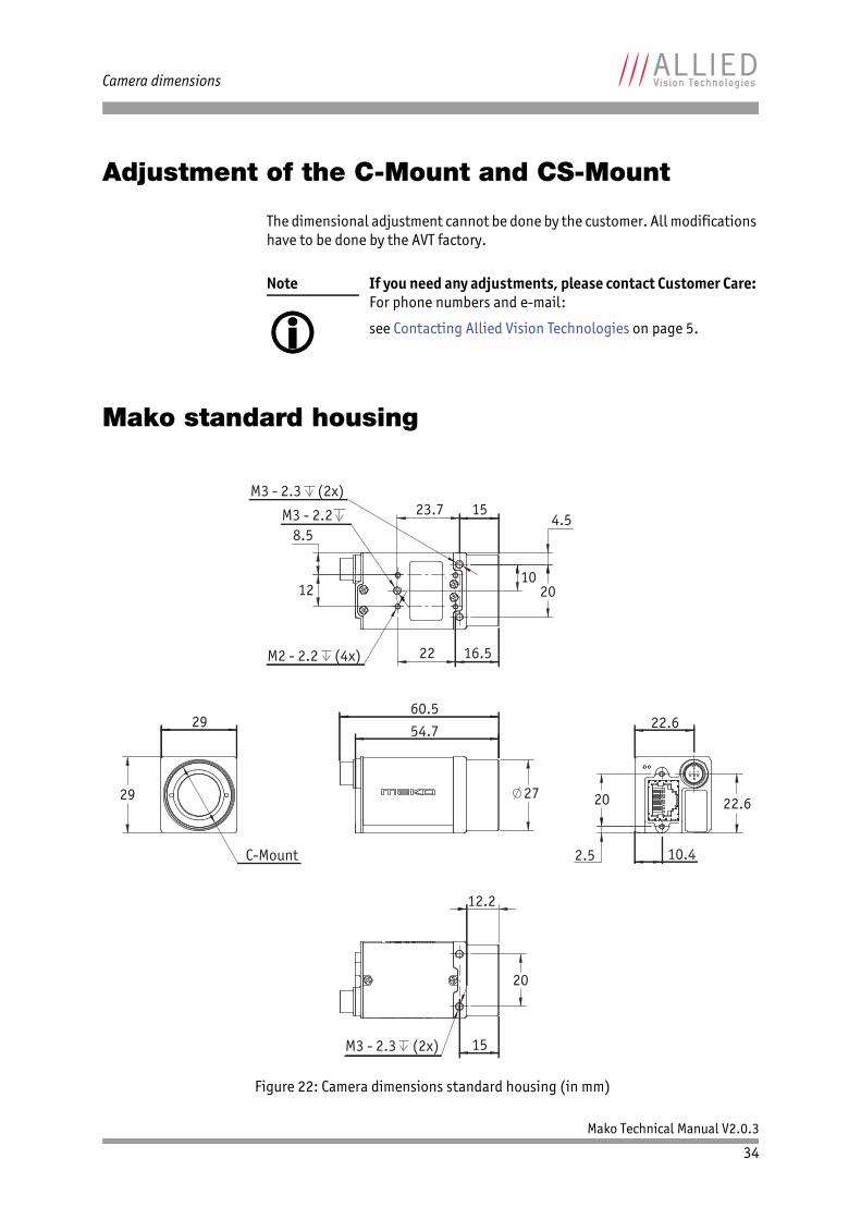
Adjustment of the C-Mount and CS-Mount
The dimensional adjustment cannot be done by the customer. All modifications have to be done by the AVT factory.
Mako standard housing
Note
If you need any adjustments, please contact Customer Care: For phone numbers and e-mail:
see Contacting Allied Vision Technologies on page 5.
Figure 22: Camera dimensions standard housing (in mm)
27
54.7 60.5
22.6
22.6
20
2.5 10.4
M2 - 2.2 (4x)
M3 - 2.3 (2x)
8.5
12
16.5 22
23.7 15 4.5
10 20
M3 - 2.2
20
15
12.2
M3 - 2.3 (2x)
C-Mount
29
29
Mako Technical Manual V2.0.3
35
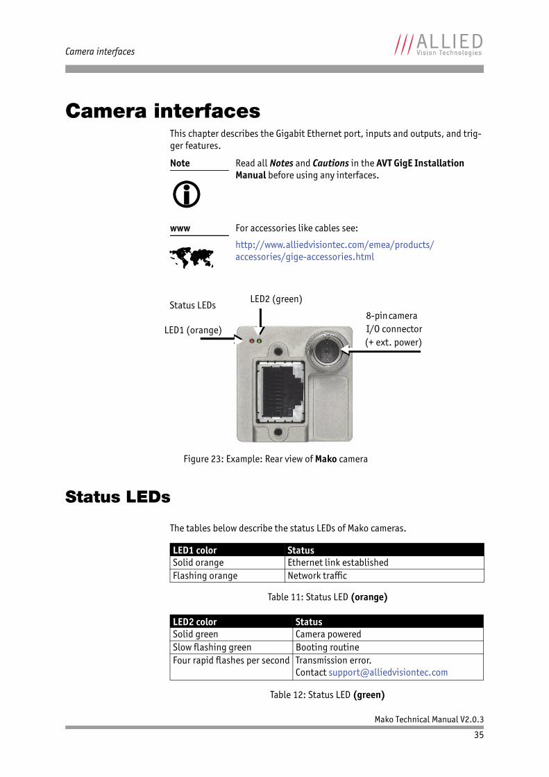
Camera interfaces
Camera interfacesThis chapter describes the Gigabit Ethernet port, inputs and outputs, and trig-ger features.
Status LEDs
The tables below describe the status LEDs of Mako cameras.
Note
Read all Notes and Cautions in the AVT GigE Installation Manual before using any interfaces.
www
For accessories like cables see:
http://www.alliedvisiontec.com/emea/products/accessories/gige-accessories.html
Figure 23: Example: Rear view of Mako camera
LED1 color StatusSolid orange Ethernet link establishedFlashing orange Network traffic
Table 11: Status LED (orange)
LED2 color StatusSolid green Camera poweredSlow flashing green Booting routineFour rapid flashes per second Transmission error.
Contact [email protected]
Table 12: Status LED (green)
Status LEDs
LED1 (orange)8-pin camera
LED2 (green)
I/O connector(+ ext. power)
Mako Technical Manual V2.0.3
36
Camera interfaces
Gigabit Ethernet port
The Gigabit Ethernet port conforms to the IEEE 802.31000BASE-T standard for Gigabit Ethernet over copper. To prevent EMI (electromagnetic interference) and for best performance, Category 6 (or higher) cables with S/STP shielding and connectors are recommended. Applications with longer cable lengths or harsh EMI conditions require Category 7 (or higher) cables.
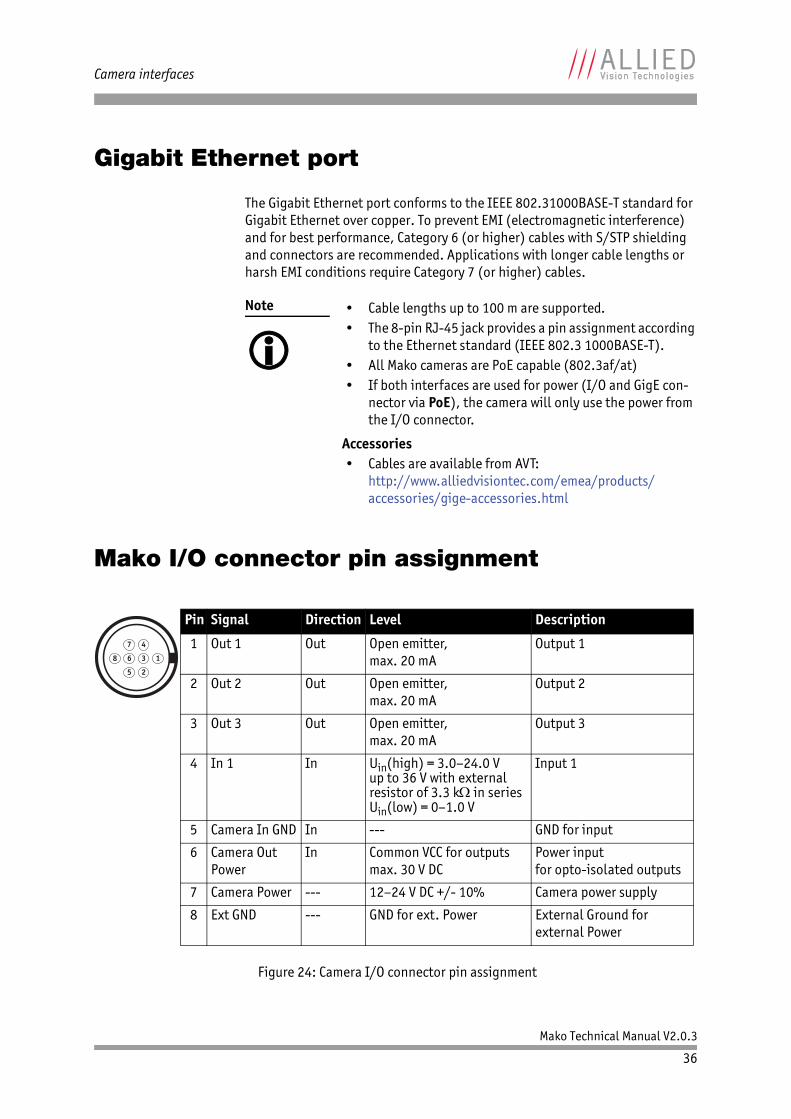
Mako I/O connector pin assignment
Note
• Cable lengths up to 100 m are supported.• The 8-pin RJ-45 jack provides a pin assignment according
to the Ethernet standard (IEEE 802.3 1000BASE-T).• All Mako cameras are PoE capable (802.3af/at)• If both interfaces are used for power (I/O and GigE con-
nector via PoE), the camera will only use the power from the I/O connector.
Accessories• Cables are available from AVT:
http://www.alliedvisiontec.com/emea/products/accessories/gige-accessories.html
Figure 24: Camera I/O connector pin assignment
25
47
1368
Pin Signal Direction Level Description
1 Out 1 Out Open emitter,max. 20 mA
Output 1
2 Out 2 Out Open emitter,max. 20 mA
Output 2
3 Out 3 Out Open emitter,max. 20 mA
Output 3
4 In 1 In Uin(high) = 3.0–24.0 Vup to 36 V with external resistor of 3.3 k in seriesUin(low) = 0–1.0 V
Input 1
5 Camera In GND In --- GND for input
6 Camera Out Power
In Common VCC for outputsmax. 30 V DC
Power inputfor opto-isolated outputs
7 Camera Power --- 12–24 V DC +/- 10% Camera power supply
8 Ext GND --- GND for ext. Power External Ground for external Power
Mako Technical Manual V2.0.3
37
Camera interfaces
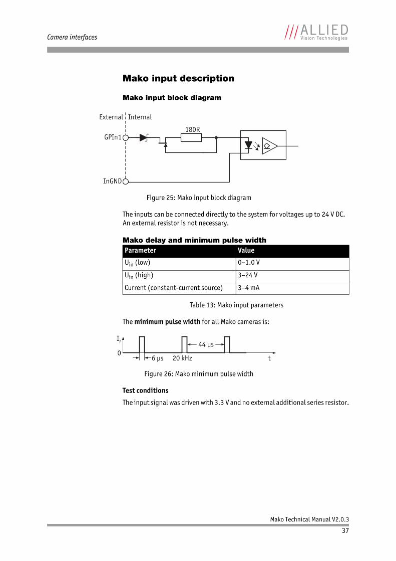
Mako input description
Mako input block diagram
The inputs can be connected directly to the system for voltages up to 24 V DC. An external resistor is not necessary.
Mako delay and minimum pulse width
The minimum pulse width for all Mako cameras is:
Test conditions
The input signal was driven with 3.3 V and no external additional series resistor.
Figure 25: Mako input block diagram
Parameter Value
Uin (low) 0–1.0 V
Uin (high) 3–24 V
Current (constant-current source) 3–4 mA
Table 13: Mako input parameters
Figure 26: Mako minimum pulse width
GPIn1
InGND
External Internal
180R
IF
0t
44 μs
6 μs 20 kHz
Mako Technical Manual V2.0.3
38
Camera interfaces
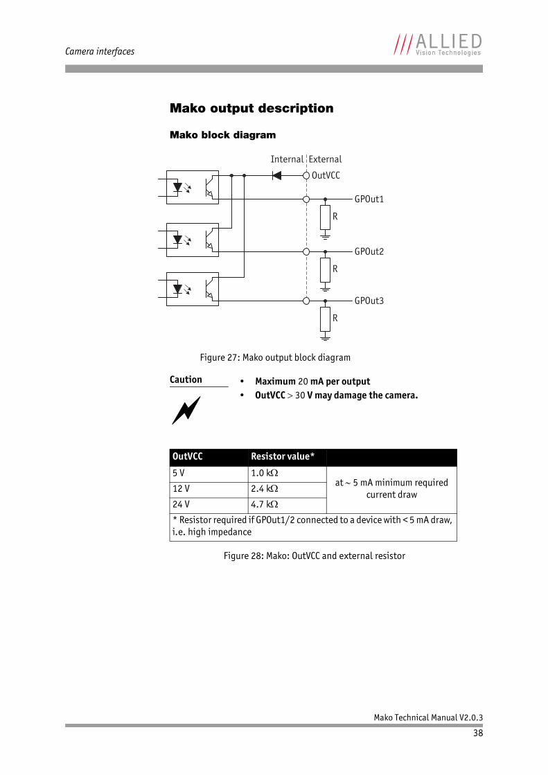
Mako output description
Mako block diagram
Figure 27: Mako output block diagram
Caution
• Maximum 20 mA per output• OutVCC 30 V may damage the camera.
OutVCC Resistor value*
5 V 1.0 kat 5 mA minimum required
current draw12 V 2.4 k
24 V 4.7 k
* Resistor required if GPOut1/2 connected to a device with < 5 mA draw, i.e. high impedance
Figure 28: Mako: OutVCC and external resistor
ExternalInternal
OutVCC
GPOut1
GPOut2
R
R
R
GPOut3
Mako Technical Manual V2.0.3
39
Camera interfaces
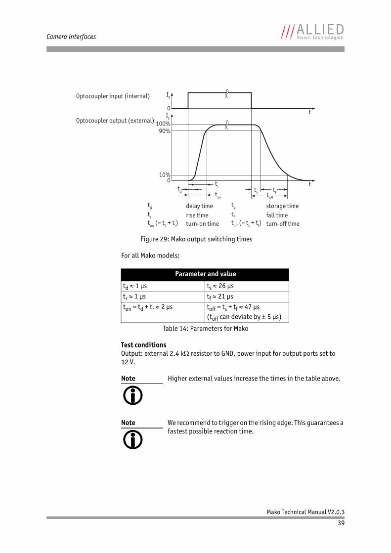
For all Mako models:
Test conditionsOutput: external 2.4 k resistor to GND, power input for output ports set to 12 V.
Figure 29: Mako output switching times
Parameter and value
td 1 μs ts 26 μs
tr 1 μs tf 21 μs
ton = td + tr 2 μs toff = ts + tf 47 μs(toff can deviate by 5 μs)
Table 14: Parameters for Mako
Note
Higher external values increase the times in the table above.
Note
We recommend to trigger on the rising edge. This guarantees a fastest possible reaction time.
IF
0IC
100%90%
10%
t
t0
delay timerise timeturn-on time
storage timefall timeturn-off time
Optocoupler input (internal)
Optocoupler output (external)
toff (= ts + tf)
td
tr
ton (= td + tr)
ts
tf
td ton
trts tftoff
Mako Technical Manual V2.0.3
40
Camera interfaces
Control signals
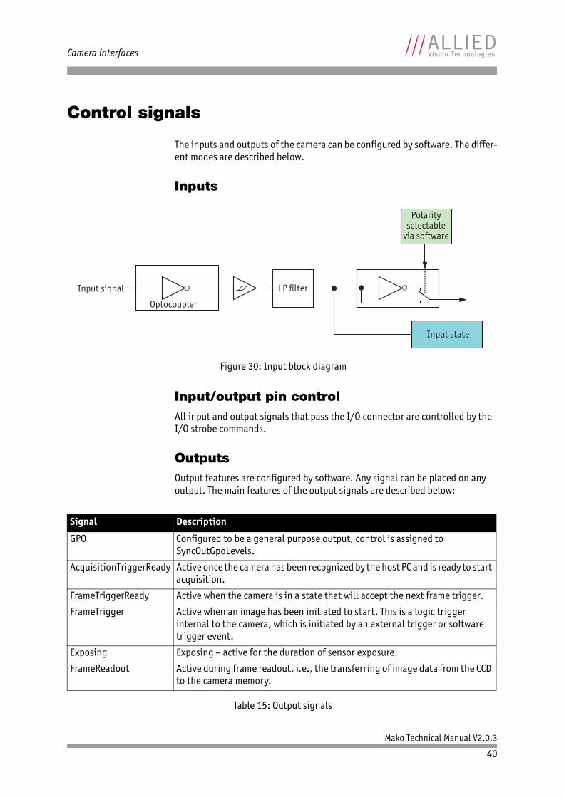
The inputs and outputs of the camera can be configured by software. The differ-ent modes are described below.
Inputs
Input/output pin controlAll input and output signals that pass the I/O connector are controlled by the I/O strobe commands.
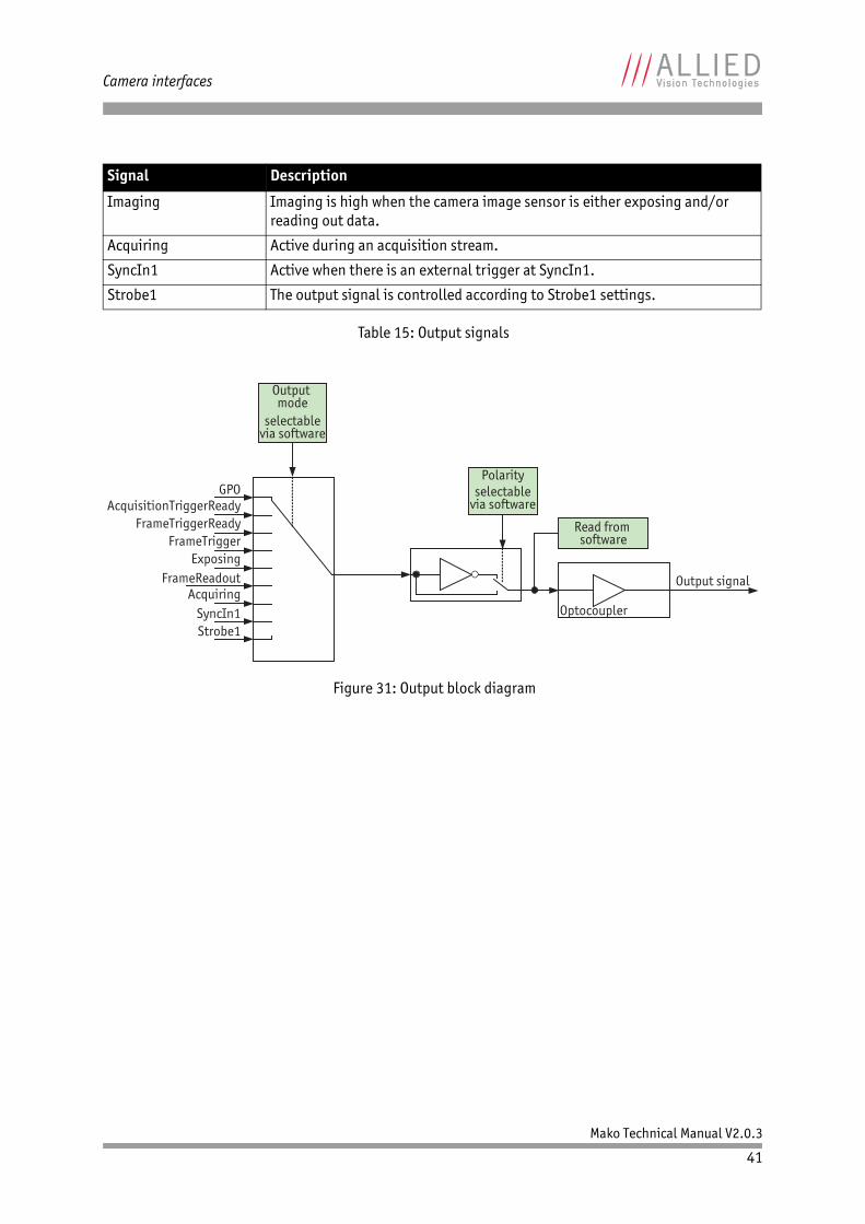
OutputsOutput features are configured by software. Any signal can be placed on any output. The main features of the output signals are described below:
Figure 30: Input block diagram
Signal Description
GPO Configured to be a general purpose output, control is assigned to SyncOutGpoLevels.
AcquisitionTriggerReady Active once the camera has been recognized by the host PC and is ready to start acquisition.
FrameTriggerReady Active when the camera is in a state that will accept the next frame trigger.
FrameTrigger Active when an image has been initiated to start. This is a logic trigger internal to the camera, which is initiated by an external trigger or software trigger event.
Exposing Exposing – active for the duration of sensor exposure.
FrameReadout Active during frame readout, i.e., the transferring of image data from the CCD to the camera memory.
Table 15: Output signals
Polarityselectable
via software
Input state
Input signal
Optocoupler
LP filter
Mako Technical Manual V2.0.3
41
Camera interfaces
Imaging Imaging is high when the camera image sensor is either exposing and/or reading out data.
Acquiring Active during an acquisition stream.
SyncIn1 Active when there is an external trigger at SyncIn1.
Strobe1 The output signal is controlled according to Strobe1 settings.
Figure 31: Output block diagram
Signal Description
Table 15: Output signals
GPO
Output signal
Optocoupler
Polarityselectable
via software
Read from software
Output mode
selectablevia software
AcquisitionTriggerReadyFrameTriggerReady
FrameTriggerExposing
FrameReadoutAcquiring
SyncIn1Strobe1
Mako Technical Manual V2.0.3
42
Camera interfaces
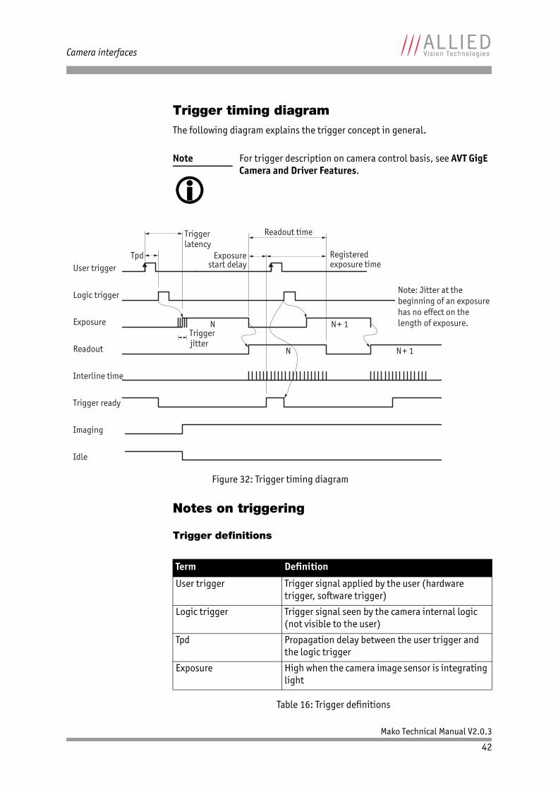
Trigger timing diagramThe following diagram explains the trigger concept in general.
Notes on triggering
Trigger definitions
Note
For trigger description on camera control basis, see AVT GigE Camera and Driver Features.
Figure 32: Trigger timing diagram
Term Definition
User trigger Trigger signal applied by the user (hardware trigger, software trigger)
Logic trigger Trigger signal seen by the camera internal logic (not visible to the user)
Tpd Propagation delay between the user trigger and the logic trigger
Exposure High when the camera image sensor is integrating light
Table 16: Trigger definitions
User trigger
Logic trigger
Exposure
Readout
Trigger ready
Imaging
Interline time
Idle
Tpd
Trigger latency
Exposure start delay
Trigger jitter
Registered exposure time
Readout time
N N+ 1
N N+ 1
Note: Jitter at thebeginning of an exposurehas no effect on thelength of exposure.
Mako Technical Manual V2.0.3
43
Camera interfaces
Trigger rules• The end of exposure will always trigger the next readout.• The end of exposure must always end after the current readout.• The start of exposure must always correspond with the interline time if
readout is true.• Exposure start delay equals the readout time minus the registered expo-
sure time.
Triggering during the Idle State
For applications requiring the shortest possible trigger latency and the smallest possible trigger jitter, the user trigger signal should be applied when imaging is false and idle is true.
Triggering during the Readout State
For applications requiring the fastest triggering cycle time whereby the camera image sensor is exposing and reading out simultaneously, the user trigger sig-nal should be applied as soon as a valid trigger ready is detected.
In this case, trigger latency and trigger jitter can be up to 1 line time since expo-sure must always begin on an Interline boundary.
Readout High when the camera image sensor is reading out data
Trigger latency Time delay between the user trigger and the start of exposure
Trigger jitter Error in the trigger latency time
Trigger ready Indicates to the user that the camera will accept the next trigger
Registered exposure time Exposure time value currently stored in the camera memory
Exposure start delay Registered exposure time subtracted from the Readout time and indicates when the next expo-sure cycle can begin such that the exposure will end after the current readout
Interline time Time between sensor row readout cycles
Imaging High when the camera image sensor is either exposing and/or reading out data
Idle High if the camera image sensor is not exposing and/or reading out data
Term Definition
Table 16: Trigger definitions
Mako Technical Manual V2.0.3
44
Description of the data path
Description of the data path
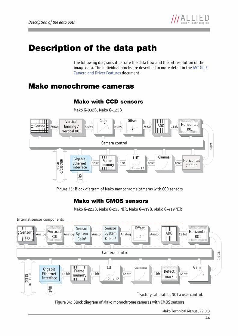
The following diagrams illustrate the data flow and the bit resolution of the image data. The individual blocks are described in more detail in the AVT GigE Camera and Driver Features document.
Mako monochrome cameras
Mako with CCD sensorsMako G-032B, Mako G-125B
Mako with CMOS sensors Mako G-223B, Mako G-223 NIR, Mako G-419B, Mako G-419 NIR
Figure 33: Block diagram of Mako monochrome cameras with CCD sensors
Figure 34: Block diagram of Mako monochrome cameras with CMOS sensors
Sensor 12 bit
12 bit
HIROSE I/ORS232
GigE
Analog
12 bit
Gamma12 bit
LUT
12 12
Verticalbinning /
Vertical ROI
12 bitHorizontal
binning
Horizontal ROI
12 bit
Analog
Gain
Camera control
Analog Analog ADCOffset
Frame memory
Gigabit Ethernet interface
HIROSE I/ORS232
12 bit
12 bit
Gigabit Ethernet interface
12 bit
LUT
12 1212 bit
Gamma
12 bitFrame
memory
GigE
‡ Factory calibrated. NOT a user control.
Sensorarray
Analog Analog 12 bitAnalog
Internal sensor components
Analog
OffsetSensorSystemGain‡
SensorSystemOffset‡
AnalogVertical
ROIHorizontal
ROIADC
12 bitDefectmask
Camera control
Gain
Mako Technical Manual V2.0.3
45
Description of the data path
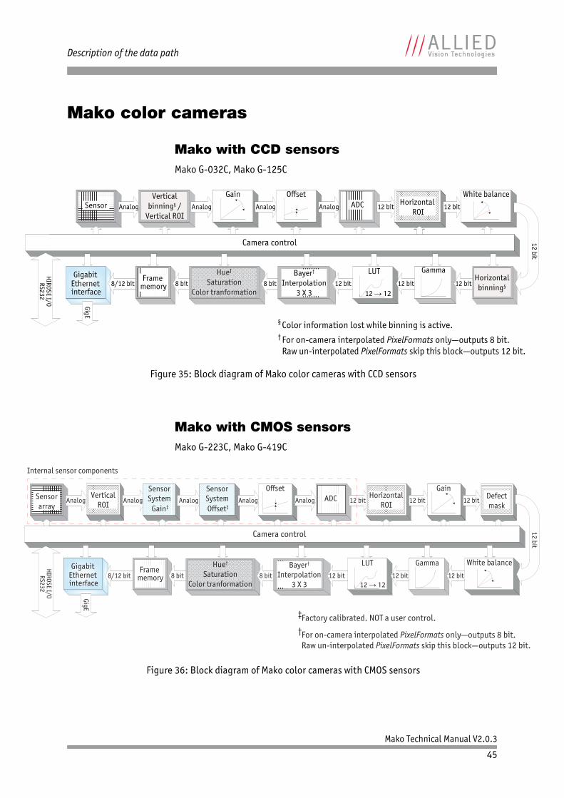
Mako color cameras
Mako with CCD sensorsMako G-032C, Mako G-125C
Mako with CMOS sensorsMako G-223C, Mako G-419C
Figure 35: Block diagram of Mako color cameras with CCD sensors
Figure 36: Block diagram of Mako color cameras with CMOS sensors
12 bit
HIROSE I/ORS232
GigE
12 bit
GammaLUT
12 12
12 bit
8 bit 8 bit8/12 bitGigabit
Ethernet interface
Frame memory
Hue†
SaturationColor tranformation
Bayer†
Interpolation3 X 3
For on-camera interpolated PixelFormats only—outputs 8 bit. Raw un-interpolated PixelFormats skip this block—outputs 12 bit.
†
12 bitHorizontal
binning§
Sensor Analog Analog ADCOffset
Analog Analog
GainVerticalbinning§ /
Vertical ROI12 bit
Horizontal ROI
12 bit
White balance
Camera control
§ Color information lost while binning is active.
HIROSE I/ORS232
Sensorarray
Analog Analog 12 bit
GigE
Analog
12 bit
Gamma
12 bit
12 bit
Gigabit Ethernet interface
Internal sensor components
12 bit
12 bit
Offset
LUT
12 128 bit 8 bit8/12 bit
Frame memory
Hue†
SaturationColor tranformation
Bayer†
Interpolation3 X 3
For on-camera interpolated PixelFormats only—outputs 8 bit. Raw un-interpolated PixelFormats skip this block—outputs 12 bit.
‡Factory calibrated. NOT a user control.
†
SensorSystem Gain‡
SensorSystem Offset‡
AnalogVertical
ROIDefectmask
12 bit
Camera control
White balance
HorizontalROI
12 bit
Gain
Analog ADC
Mako Technical Manual V2.0.3
46
Description of the data path
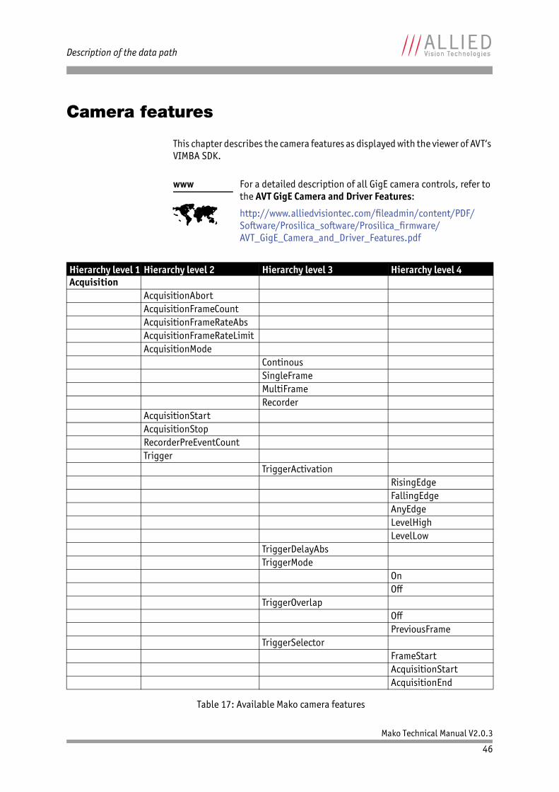
Camera features
This chapter describes the camera features as displayed with the viewer of AVT‘s VIMBA SDK.
www
For a detailed description of all GigE camera controls, refer to the AVT GigE Camera and Driver Features:
http://www.alliedvisiontec.com/fileadmin/content/PDF/Software/Prosilica_software/Prosilica_firmware/AVT_GigE_Camera_and_Driver_Features.pdf
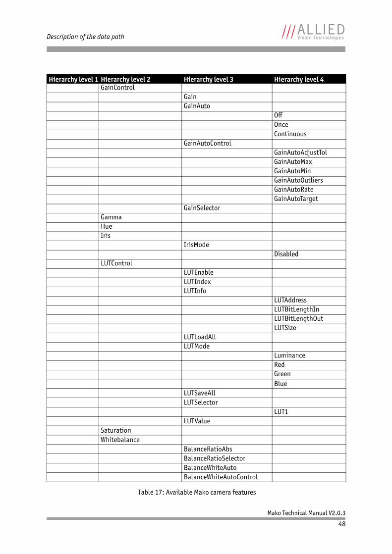
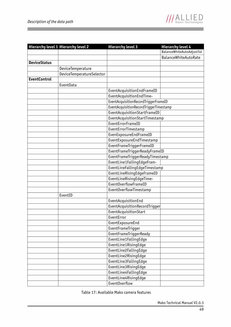
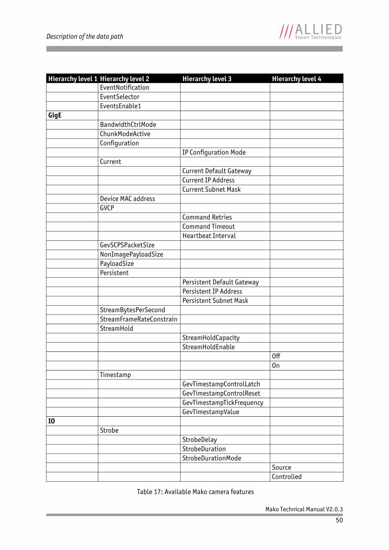
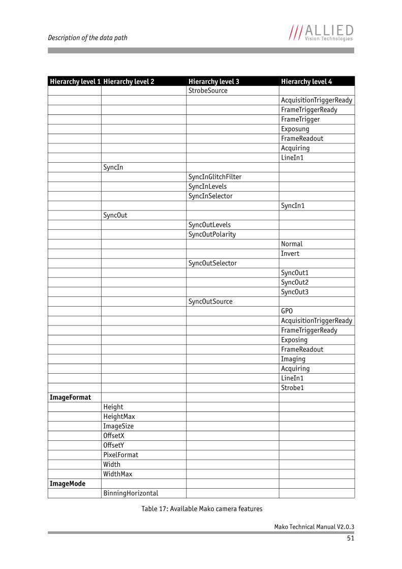
Hierarchy level 1 Hierarchy level 2 Hierarchy level 3 Hierarchy level 4Acquisition
AcquisitionAbortAcquisitionFrameCountAcquisitionFrameRateAbsAcquisitionFrameRateLimitAcquisitionMode
ContinousSingleFrameMultiFrameRecorder
AcquisitionStartAcquisitionStopRecorderPreEventCountTrigger
TriggerActivationRisingEdgeFallingEdgeAnyEdgeLevelHighLevelLow
TriggerDelayAbsTriggerMode
OnOff
TriggerOverlapOffPreviousFrame
TriggerSelectorFrameStartAcquisitionStartAcquisitionEnd
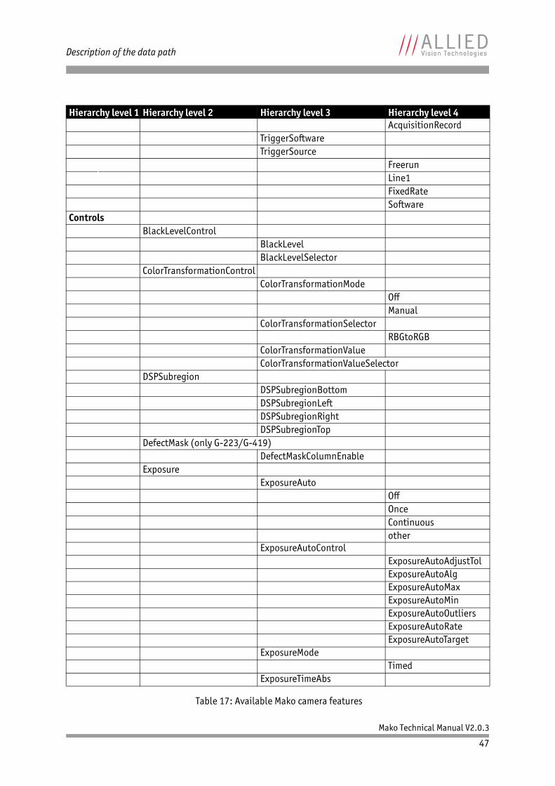
Table 17: Available Mako camera features
Mako Technical Manual V2.0.3
47
Description of the data path
AcquisitionRecordTriggerSoftwareTriggerSource
FreerunLine1FixedRateSoftware
ControlsBlackLevelControl
BlackLevelBlackLevelSelector
ColorTransformationControlColorTransformationMode
OffManual
ColorTransformationSelectorRBGtoRGB
ColorTransformationValueColorTransformationValueSelector
DSPSubregionDSPSubregionBottomDSPSubregionLeftDSPSubregionRightDSPSubregionTop
DefectMask (only G-223/G-419)DefectMaskColumnEnable
ExposureExposureAuto
OffOnceContinuousother
ExposureAutoControlExposureAutoAdjustTolExposureAutoAlgExposureAutoMaxExposureAutoMinExposureAutoOutliersExposureAutoRateExposureAutoTarget
ExposureModeTimed
ExposureTimeAbs
Hierarchy level 1 Hierarchy level 2 Hierarchy level 3 Hierarchy level 4
Table 17: Available Mako camera features
Mako Technical Manual V2.0.3
48
Description of the data path
GainControlGainGainAuto
OffOnceContinuous
GainAutoControlGainAutoAdjustTolGainAutoMaxGainAutoMinGainAutoOutliersGainAutoRateGainAutoTarget
GainSelectorGammaHueIris
IrisModeDisabled
LUTControlLUTEnableLUTIndexLUTInfo
LUTAddressLUTBitLengthInLUTBitLengthOutLUTSize
LUTLoadAllLUTMode
LuminanceRedGreenBlue
LUTSaveAllLUTSelector
LUT1LUTValue
SaturationWhitebalance
BalanceRatioAbsBalanceRatioSelectorBalanceWhiteAutoBalanceWhiteAutoControl
Hierarchy level 1 Hierarchy level 2 Hierarchy level 3 Hierarchy level 4
Table 17: Available Mako camera features
Mako Technical Manual V2.0.3
49
Description of the data path
BalanceWhiteAutoAdjustTol
BalanceWhiteAutoRateDeviceStatus
DeviceTemperatureDeviceTemperatureSelector
EventControlEventData
EventAcquisitionEndFrameIDEventAcquisitionEndTime-EventAcquisitionRecordTriggerFrameIDEventAcquisitionRecordTriggerTimestampEventAcquisitionStartFrameIDEventAcquisitionStartTimestampEventErrorFrameIDEventErrorTimestampEvenExposureEndFrameIDEventExposureEndTimestampEventFrameTriggerFrameIDEventFrameTriggerReadyFrameIDEventFrameTriggerReadyTimestampEventLine1FallingEdgeFram-EventLineFallingEdgeTimestampEventLineRisingEdgeFrameIDEventLineRisingEdgeTime-EventOverflowFrameIDEventOverflowTimestamp
EventIDEventAcquisitionEndEventAcquisitionRecordTriggerEventAcquisitionStartEventErrorEventExposureEndEventFrameTriggerEventFrameTriggerReadyEventLine1FallingEdgeEventLine1RisingEdgeEventLine2FallingEdgeEventLine2RisingEdgeEventLine3FallingEdgeEventLine3RisingEdgeEventLine4FallingEdgeEventLine4RisingEdgeEventOverflow
Hierarchy level 1 Hierarchy level 2 Hierarchy level 3 Hierarchy level 4
Table 17: Available Mako camera features
Mako Technical Manual V2.0.3
50
Description of the data path
EventNotificationEventSelectorEventsEnable1
GigEBandwidthCtrlModeChunkModeActiveConfiguration
IP Configuration ModeCurrent
Current Default GatewayCurrent IP AddressCurrent Subnet Mask
Device MAC addressGVCP
Command RetriesCommand TimeoutHeartbeat Interval
GevSCPSPacketSizeNonImagePayloadSizePayloadSizePersistent
Persistent Default GatewayPersistent IP AddressPersistent Subnet Mask
StreamBytesPerSecondStreamFrameRateConstrainStreamHold
StreamHoldCapacityStreamHoldEnable
OffOn
TimestampGevTimestampControlLatchGevTimestampControlResetGevTimestampTickFrequencyGevTimestampValue
IOStrobe
StrobeDelayStrobeDurationStrobeDurationMode
SourceControlled
Hierarchy level 1 Hierarchy level 2 Hierarchy level 3 Hierarchy level 4
Table 17: Available Mako camera features
Mako Technical Manual V2.0.3
51
Description of the data path
StrobeSourceAcquisitionTriggerReadyFrameTriggerReadyFrameTriggerExposungFrameReadoutAcquiringLineIn1
SyncInSyncInGlitchFilterSyncInLevelsSyncInSelector
SyncIn1SyncOut
SyncOutLevelsSyncOutPolarity
NormalInvert
SyncOutSelectorSyncOut1SyncOut2SyncOut3
SyncOutSourceGPOAcquisitionTriggerReadyFrameTriggerReadyExposingFrameReadoutImagingAcquiringLineIn1Strobe1
ImageFormatHeightHeightMaxImageSizeOffsetXOffsetYPixelFormatWidthWidthMax
ImageModeBinningHorizontal
Hierarchy level 1 Hierarchy level 2 Hierarchy level 3 Hierarchy level 4
Table 17: Available Mako camera features
Mako Technical Manual V2.0.3
52
Description of the data path
BinningVertical SensorHeightSensorWidth
InfoDeviceFirmwareVersionDeviceIDDeviceModelNameDevicePartNumberDeviceScanTypeDeviceVendorNameFirmwareVerBuildFirmwareVerMajorFirmwareVerMinorSensorBitsSensorType
SavedUserSetsUserSetDefaultSelector
DefaultUserSet1UserSet2UserSet3
UserSetLoadUserSetSaveUserSetSelector
DefaultUserSet1UserSet2UserSet3
StreamInfo
GSVP Filter VersionMulticast
MulticastEnableMulticast IP Address
SettingsGSVP Adjust Packet SizeGSVP Burst SizeGSVP Driver SelectorGSVP Host Receive BuffersGSVP Max Look BackGSVP Max RequestsGSVP Max Wait SizeGSVP Missing Size
Hierarchy level 1 Hierarchy level 2 Hierarchy level 3 Hierarchy level 4
Table 17: Available Mako camera features
Frame memory
An image is normally captured and transported in consecutive steps. The image is taken, read out from the sensor, digitized and sent over the Gigabit Ethernet network. Mako cameras are equipped with a RAM. Table 18 shows how many frames can be stored by each model.
The memory operates according to the FIFO (first in, first out) principle. This makes addressing for individual images unnecessary.
GSVP Packet SizeGSVP Tilting SizeGSVP Timeout
StatisticsStat Frame RateStat Frames DeliveredStat Frames DroppedStat Frames RescuedStat Frames ShovedStat Frames UnderrunStat Local RateStat Packets MissedStat Packets ReceivedStat Packets RequestedStat Packets ResentStat Time Elapsed
Note
The number of frames (StreamHoldCapacity) depends on resolution, pixel format, and packet size. Stated number of frames is typical for full resolution, Mono8/Bayer8, and GevSCPSPacketSize = 8192.
Model Memory size Pixel format / Resolution / Packet size
Mako G-032B/C 64 MB memory: 202 framesMono8/Bayer8
Full resolution
Payload size of 8192 bytes per packet
Mako G-125B/C 64 MB memory: 52 frames
Mako G-223B/C 64 MB memory: 29 frames
Mako G-419B/C 64 MB memory: 15 frames
Table 18: Image memory size (typical; see note above)
Hierarchy level 1 Hierarchy level 2 Hierarchy level 3 Hierarchy level 4
Table 17: Available Mako camera features
Mako Technical Manual V2.0.3
54
Resolution and ROI frame rates
Resolution and ROI frame ratesThis section charts the resulting frame rate from changing sensor height from full image to a single line. Unless otherwise noted, sensors do not give an increase in readout speed with a reduction in width.
Note
• Data was generated using StreamBytesPerSecond = 124
MB/s (full bandwidth) and an 8-bit pixel format. Frame rates may be lower if using network hardware incapable of 124 MB/s.
• ROIs are taken as center image for maximum speed advantage, where attribute RegionY = (full sensor height – ROI height)/2.
• BinningY is horizontal row summing on CCD before read-out. The frame rate for an ROI at the same effective height as binning will be slower because the CCD still needs to read out the “fast readout rows” in ROI mode.
Mako Technical Manual V2.0.3
55
Resolution and ROI frame rates
Mako G-032B/C: ROI frame rates
Maximum frame rate at full resolution according to formula: 102.31 fps
* CCD = theoretical maximum frame rate (in fps) of CCD according to given formula
Formula 1: Mako G-032: theoretical maximum frame rate of CCD
Figure 37: Frame rates Mako G-032 as function of ROI height[width=658]
ROI height CCD*492 102.31480 104.51320 146.61240 183.59120 295.33
60 424.5130 543.3310 667.98
2 735.48
Table 19: Frame rates (fps) of Mako G-032 as function of ROI height (pixel) [width=658]
Max. frame rate of CCD1
19.46 μs ROI height 2.29 μs 492 ROI height– 195.81 μs+ +------------------------------------------------------------------------------------------------------------------------------------------------------=
100150200250300350400450500550600650700750
0 100 200 300 400 500
Fram
e ra
te [
fps]
ROI height [pixel]
Mako Technical Manual V2.0.3
56
Resolution and ROI frame rates
Mako G-125B/C: ROI frame rates
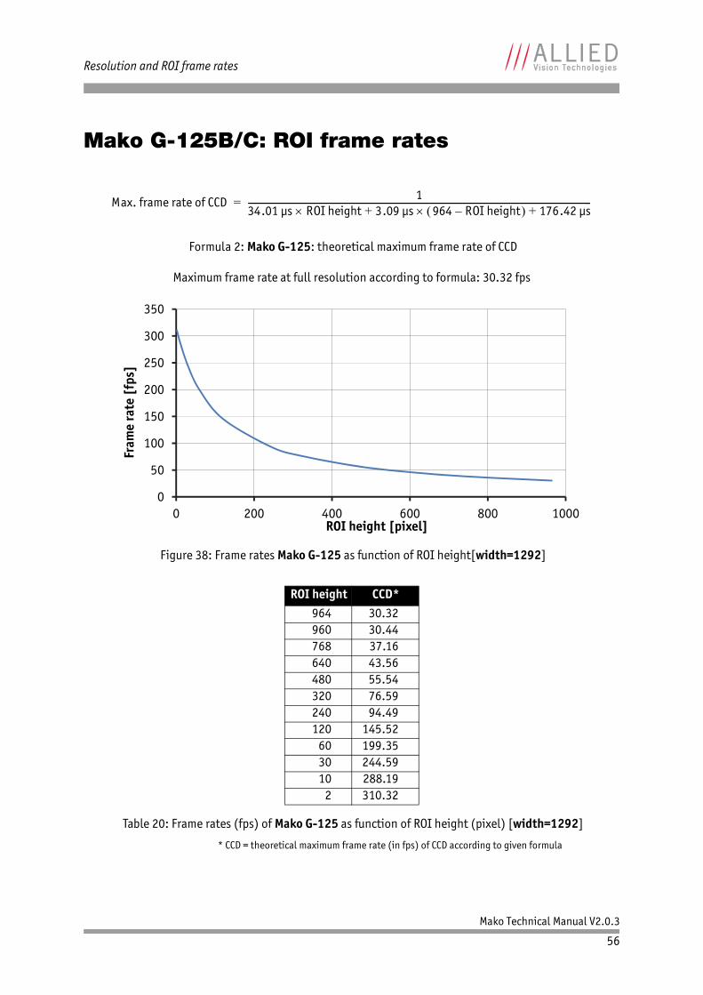
Maximum frame rate at full resolution according to formula: 30.32 fps
* CCD = theoretical maximum frame rate (in fps) of CCD according to given formula
Formula 2: Mako G-125: theoretical maximum frame rate of CCD
Figure 38: Frame rates Mako G-125 as function of ROI height[width=1292]
ROI height CCD*964 30.32960 30.44768 37.16640 43.56480 55.54320 76.59240 94.49120 145.52
60 199.3530 244.5910 288.19
2 310.32
Table 20: Frame rates (fps) of Mako G-125 as function of ROI height (pixel) [width=1292]
Max. frame rate of CCD1
34.01 μs ROI height 3.09 μs 964 ROI height– 176.42 μs+ +------------------------------------------------------------------------------------------------------------------------------------------------------=
0
50
100
150
200
250
300
350
0 200 400 600 800 1000
Fram
e ra
te [
fps]
ROI height [pixel]
Mako Technical Manual V2.0.3
57
Resolution and ROI frame rates
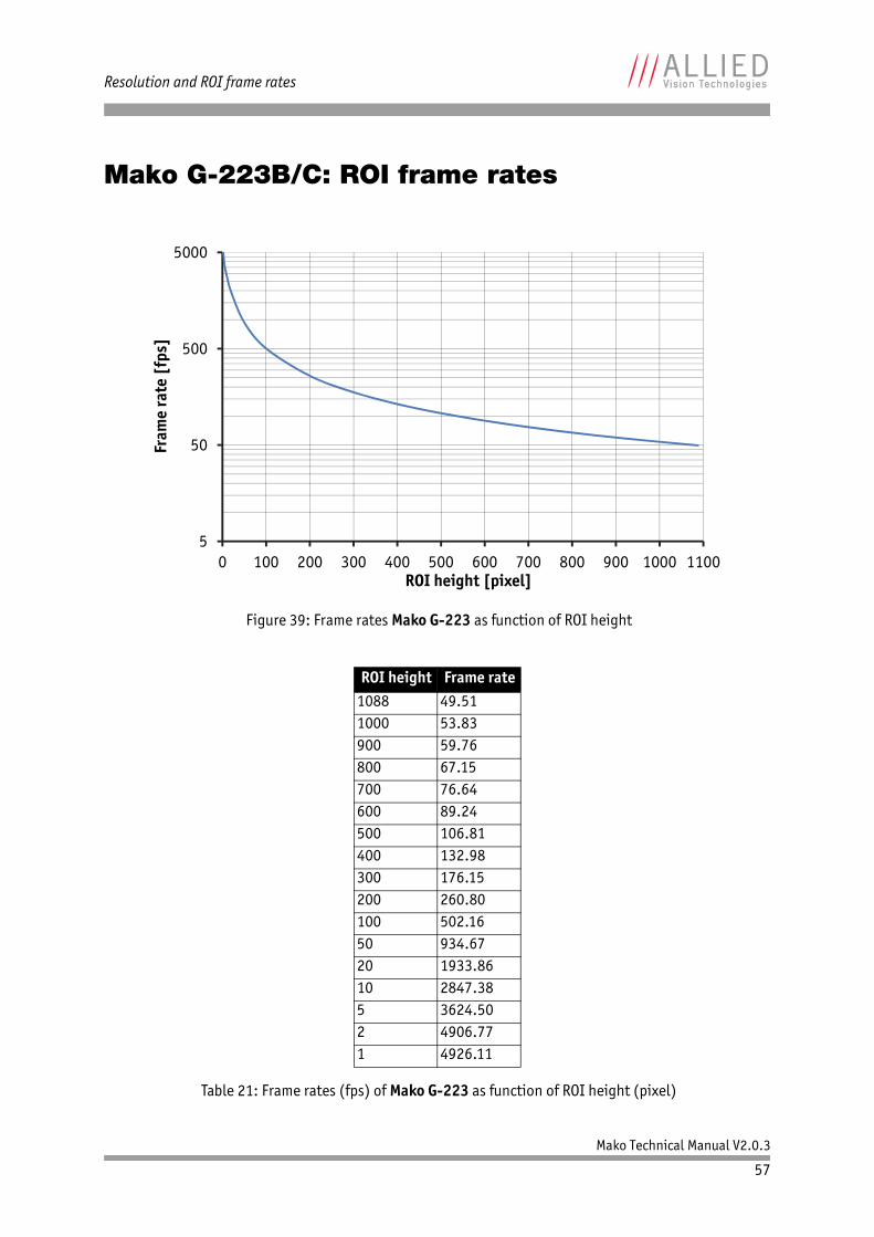
Mako G-223B/C: ROI frame rates
Figure 39: Frame rates Mako G-223 as function of ROI height
ROI height Frame rate1088 49.511000 53.83900 59.76800 67.15700 76.64600 89.24500 106.81400 132.98300 176.15200 260.80100 502.1650 934.6720 1933.8610 2847.385 3624.502 4906.771 4926.11
Table 21: Frame rates (fps) of Mako G-223 as function of ROI height (pixel)
5
50
500
5000
0 100 200 300 400 500 600 700 800 900 1000 1100
Fram
e ra
te [
fps]
ROI height [pixel]
Mako Technical Manual V2.0.3
58
Resolution and ROI frame rates
Mako G-419B/C: ROI frame rates
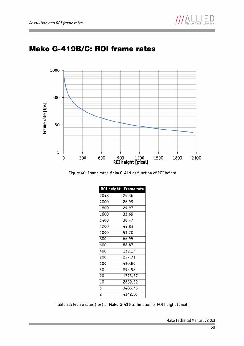
Figure 40: Frame rates Mako G-419 as function of ROI height
ROI height Frame rate2048 26.362000 26.991800 29.971600 33.691400 38.471200 44.831000 53.70800 66.95600 88.87400 132.17200 257.71100 490.8050 895.9820 1775.5710 2639.225 3486.752 4342.16
Table 22: Frame rates (fps) of Mako G-419 as function of ROI height (pixel)
5
50
500
5000
0 300 600 900 1200 1500 1800 2100
Fram
e ra
te [
fps]
ROI height [pixel]
Mako Technical Manual V2.0.3
59
Appendix
Appendix
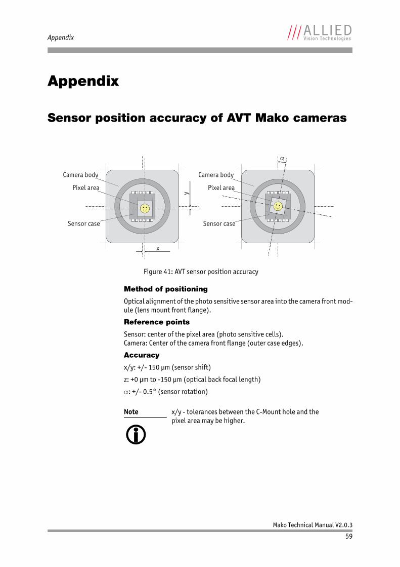
Sensor position accuracy of AVT Mako cameras
Method of positioning
Optical alignment of the photo sensitive sensor area into the camera front mod-ule (lens mount front flange).
Reference points
Sensor: center of the pixel area (photo sensitive cells).Camera: Center of the camera front flange (outer case edges).
Accuracy
x/y: +/- 150 μm (sensor shift)
z: +0 μm to -150 μm (optical back focal length)
α: +/- 0.5° (sensor rotation)
Figure 41: AVT sensor position accuracy
Note
x/y - tolerances between the C-Mount hole and the pixel area may be higher.
x
y
Sensor case
Camera body
Pixel area
Sensor case
Camera body
Pixel area
Mako Technical Manual V2.0.3
60
Index
Index
A
acquiring (signal) .................................... 41acquisition stream ................................... 41AcquisitionTriggerReady (signal) ................ 40AVT sensor position accuracy ...................... 59
B
Block diagramMako color cameras with CCD sensors ..... 45Mako color cameras with CMOS sensors ... 45Mako mono cameras with CCD sensors ..... 44Mako mono cameras with CMOS sensors .. 44
C
camera interfaces .................................... 35camera lenses ......................................... 28Camera rear view ..................................... 35Camera standard housing .......................... 34CE ......................................................... 14Cleaning instructions ............................. 9, 11Compressed air ........................................ 12Cross section
C-Mount ........................................... 32CS-Mount .......................................... 33
D
declaration of conformity .......................... 14Description of the data path ....................... 44document history ....................................... 6duration of sensor exposure ....................... 40Dust-free clean-room ................................ 11
E
exposing (signal) ..................................... 40exposing (trigger) .................................... 43exposure (definition) ............................... 42exposure cycle (trigger) ............................ 43exposure start delay (signal) ...................... 43exposure time value (trigger) ..................... 43external trigger ....................................... 40external trigger at SyncIn1 ........................ 41
F
FCC Class B ............................................. 14focal length ............................................ 29frame readout ......................................... 40frame trigger .......................................... 40FrameReadout (signal) ............................. 40FrameTrigger (signal) ............................... 40FrameTriggerReady (signal) ....................... 40
G
GenICam ................................................ 13Gigabit Ethernet ...................................... 13Gigabit Ethernet interface ......................... 13GigE ...................................................... 13GigE cameras
Mako ............................................... 13GigE Vision ............................................. 13GPO (general purpose output) .................... 40
I
Identifying impurities ............................... 10idle (signal) ............................................ 43imaging (signal) ................................. 41, 43Input block diagram ................................. 40inputs
in detail ........................................... 40integrating light (trigger) ......................... 42interline boundary ................................... 43interline time (signal) .............................. 43
L
legal notice .............................................. 2Locating impurities .................................. 10logic trigger ........................................... 40logic trigger (definition) ........................... 42
M
Mako GigE cameras ................................... 13Minimum pulse width ................................ 37
Mako Technical Manual V2.0.3
61
Index
O
Output block diagram ............................... 41Output signals ......................................... 40Output switching times ............................. 39outputs .................................................. 40OutVCC ................................................... 38
P
PoE ....................................................... 36propagation delay (trigger) ....................... 42
R
reading out data (trigger) .......................... 43readout (definition) ................................. 43readout data (trigger) ............................... 43registered exposure time (signal) ................ 43RoHS (2002/95/EC) ................................. 14
S
sensor row readout cycles .......................... 43software trigger ....................................... 40specifications .......................................... 15Spectral sensitivity
Mako G-032B ..................................... 24Mako G-032C ..................................... 24Mako G-125B ..................................... 25Mako G-125C ..................................... 25Mako G-223B (NIR) ............................. 26Mako G-223C ..................................... 26Mako G-419B (NIR) ............................. 27Mako G-419C ..................................... 27
spectral transmissionIR cut filter ....................................... 28type Hoya C5000 ................................ 28
start acquisition ...................................... 40Strobe1 (signal) ...................................... 41styles ...................................................... 7symbols ................................................... 7SyncIn1 (signal) ...................................... 41SyncOutGpoLevels .................................... 40system components .................................. 28
T
time delay (trigger) .................................. 43timing diagram
trigger ............................................. 42Tpd (definition) ....................................... 42trigger
timing diagram .................................. 42trigger definitions .................................... 42trigger jitter (definition) ........................... 43trigger latency (definition) ........................ 43trigger latency time .................................. 43trigger ready (signal) ............................... 43trigger rules ........................................... 43Tripod dimensions .................................... 31types
Mako GigE cameras ............................. 13
U
user trigger (definition) ............................ 42
W
Warranty .................................................. 9Warranty precautions ................................. 9