Embed Size (px)
Citation preview
Engineered for flexibility and performance™
Magnitude™ Magnetic Bearing Centrifugal Chillers Catalog 602-2 Model WMC, B Vintage • 145 to 400 tons • 500 to 1400 kW • R-134a
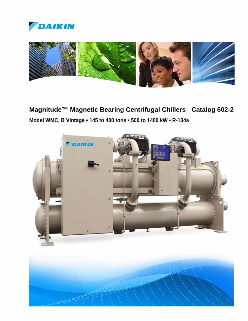
Cutaway View of Magnetic Bearing Compressor
Compressor Major Running Gear Components
MicroTech II® Controller Operator Interface, Home Screen
Catalog 602-2 3
Table of Contents The New Compressor Technology ........................................................................................................................ 4
Benefit Summary ............................................................................................................................................ 4 The Compressor Technology .......................................................................................................................... 5 Low Operating Costs ...................................................................................................................................... 6 Environmental Responsibility ........................................................................................................................ 6 Unit Control Features ..................................................................................................................................... 7 MicroTech II ® Control Features and Benefits ................................................................................................ 8
Unit Design Features ........................................................................................................................................... 12 Chiller Identification ........................................................................................................................................... 16 Sound Data ........................................................................................................................................................... 17
One-Third Octave Band ................................................................................................................................ 17 Dimensions ........................................................................................................................................................... 19
Marine Water Box Dimensions ..................................................................................................................... 25 Physical Data and Weights ................................................................................................................................. 27
Physical Data ................................................................................................................................................ 28 Relief Valves ......................................................................................................................................................... 29 Electrical Data ..................................................................................................................................................... 30
Power Factor Correction ............................................................................................................................... 40 VFD Line Harmonics ................................................................................................................................... 40
Application Considerations ................................................................................................................................ 42 Location ........................................................................................................................................................ 42 Optimum Water Temperatures and Flow ...................................................................................................... 42 System Water Volume ................................................................................................................................... 44 Pump Control ................................................................................................................................................ 44 Retrofit Knockdown ..................................................................................................................................... 45 Pressure Drop Curves ................................................................................................................................... 46
Options and Accessories...................................................................................................................................... 49 Refrigerant Recovery Units ................................................................................................................................ 51 Refrigerant Monitors .......................................................................................................................................... 52 Specifications ....................................................................................................................................................... 54
*Unit Controllers are LONMARK certified with an optional LONWORKS communication module.
Manufactured in an ISO Certified Facility
Document: Catalog 602-2 Original Issue Date: February 2009 Revision Issue Date: May 2013 Replaces: February 2013 Software Version V08.20
©2013 Daikin Applied. Illustrations and data cover the Daikin product at the time of publication and we reserve the right to make changes in design and construction at anytime without notice. ™® The following are trademarks or registered trademarks of their respective companies: BACnet from ASHRAE; LONMARK, LonTalk, LONWORKS, and the LONMARK logo are managed, granted and used by LONMARK International under a license granted by Echelon Corporation; Modbus from Schneider Electric; MicroTech II, Open Choices from Daikin.
Modbus™
Applies to 60 HZ only Applies to 60 HZ only
4 Catalog 602-2
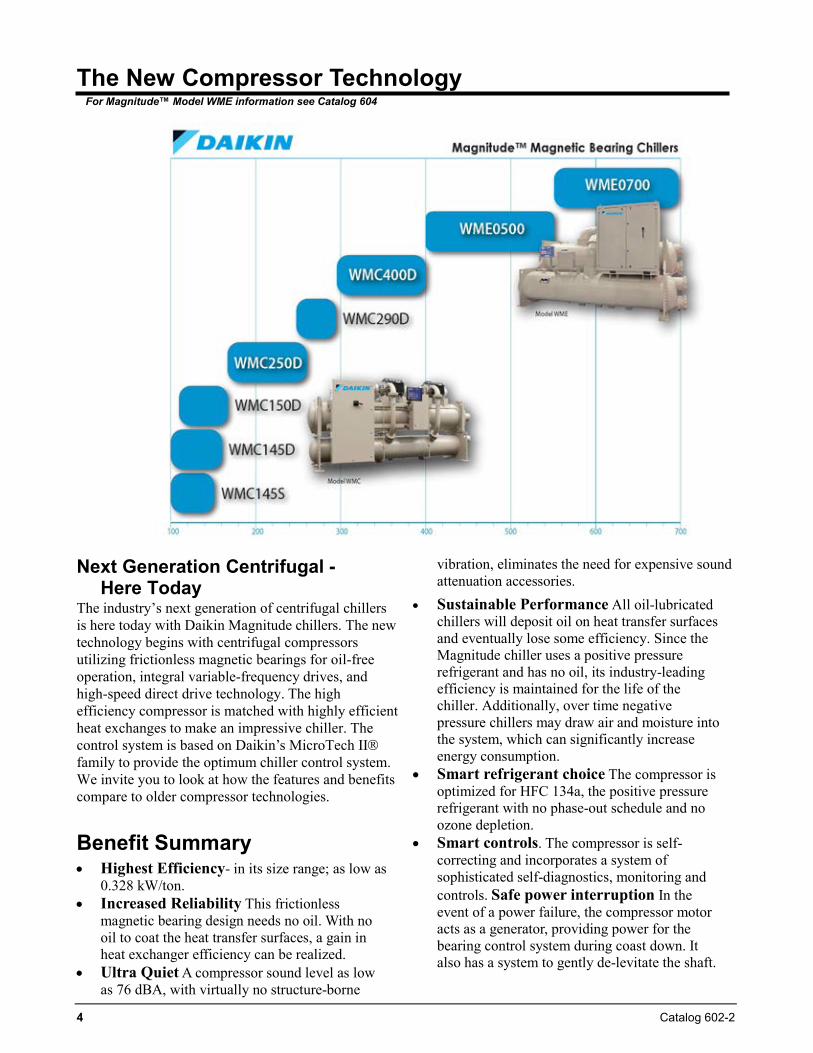
The New Compressor Technology For Magnitude™ Model WME information see Catalog 604
Next Generation Centrifugal -Here Today
The industry’s next generation of centrifugal chillers is here today with Daikin Magnitude chillers. The new technology begins with centrifugal compressors utilizing frictionless magnetic bearings for oil-free operation, integral variable-frequency drives, and high-speed direct drive technology. The high efficiency compressor is matched with highly efficient heat exchanges to make an impressive chiller. The control system is based on Daikin’s MicroTech II family to provide the optimum chiller control system. We invite you to look at how the features and benefits compare to older compressor technologies.
Benefit Summary • Highest Efficiency- in its size range; as low as
0.328 kW/ton. • Increased Reliability This frictionless
magnetic bearing design needs no oil. With no oil to coat the heat transfer surfaces, a gain in heat exchanger efficiency can be realized.
• Ultra Quiet A compressor sound level as lowas 76 dBA, with virtually no structure-borne
vibration, eliminates the need for expensive sound attenuation accessories.
• Sustainable Performance All oil-lubricatedchillers will deposit oil on heat transfer surfacesand eventually lose some efficiency. Since theMagnitude chiller uses a positive pressurerefrigerant and has no oil, its industry-leadingefficiency is maintained for the life of thechiller. Additionally, over time negativepressure chillers may draw air and moisture intothe system, which can significantly increaseenergy consumption.
• Smart refrigerant choice The compressor isoptimized for HFC 134a, the positive pressurerefrigerant with no phase-out schedule and noozone depletion.
• Smart controls. The compressor is self-correcting and incorporates a system ofsophisticated self-diagnostics, monitoring andcontrols. Safe power interruption In theevent of a power failure, the compressor motoracts as a generator, providing power for thebearing control system during coast down. Italso has a system to gently de-levitate the shaft.
Catalog 602-2 5
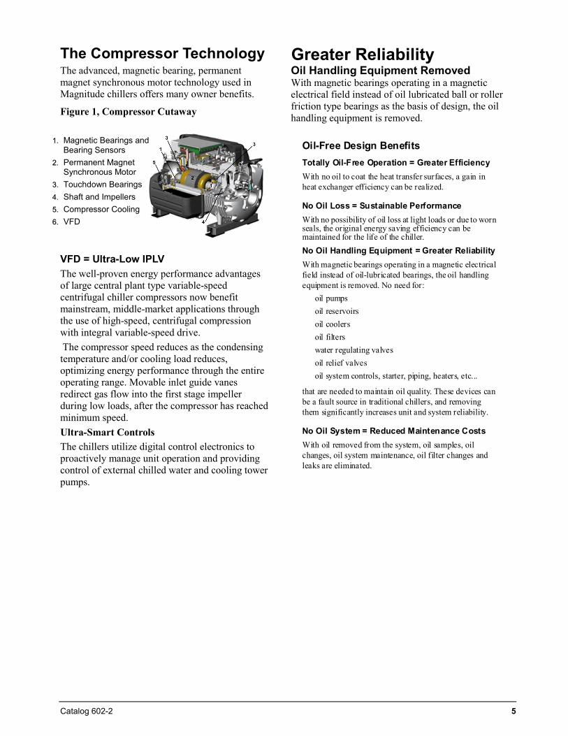
11.. Magnetic Bearings and Bearing Sensors
22.. Permanent Magnet Synchronous Motor
33.. Touchdown Bearings 44.. Shaft and Impellers 55.. Compressor Cooling 66.. VFD
The Compressor Technology The advanced, magnetic bearing, permanent magnet synchronous motor technology used in Magnitude chillers offers many owner benefits.
Figure 1, Compressor Cutaway
VFD = Ultra-Low IPLV The well-proven energy performance advantages of large central plant type variable-speed centrifugal chiller compressors now benefit mainstream, middle-market applications through the use of high-speed, centrifugal compression with integral variable-speed drive. The compressor speed reduces as the condensing temperature and/or cooling load reduces, optimizing energy performance through the entire operating range. Movable inlet guide vanes redirect gas flow into the first stage impeller during low loads, after the compressor has reached minimum speed. Ultra-Smart Controls The chillers utilize digital control electronics to proactively manage unit operation and providing control of external chilled water and cooling tower pumps.
Greater Reliability Oil Handling Equipment Removed With magnetic bearings operating in a magnetic electrical field instead of oil lubricated ball or roller friction type bearings as the basis of design, the oil handling equipment is removed.
Oil-Free Design BenefitsTotally Oil-Free Operation = Greater EfficiencyWith no oil to coat the heat transfer surfaces, a gain in heat exchanger efficiency can be realized.
No Oil Loss = Sustainable PerformanceWith no possibility of oil loss at light loads or due to worn seals, the original energy saving efficiency can be maintained for the life of the chiller.No Oil Handling Equipment = Greater ReliabilityWith magnetic bearings operating in a magnetic electrical field instead of oil-lubricated bearings, the oil handling equipment is removed. No need for:
oil pumpsoil reservoirsoil coolersoil filterswater regulating valvesoil relief valves oil system controls, starter, piping, heaters, etc...
that are needed to maintain oil quality. These devices can be a fault source in traditional chillers, and removing them significantly increases unit and system reliability.
No Oil System = Reduced Maintenance CostsWith oil removed from the system, oil samples, oil changes, oil system maintenance, oil filter changes and leaks are eliminated.
6 Catalog 602-2
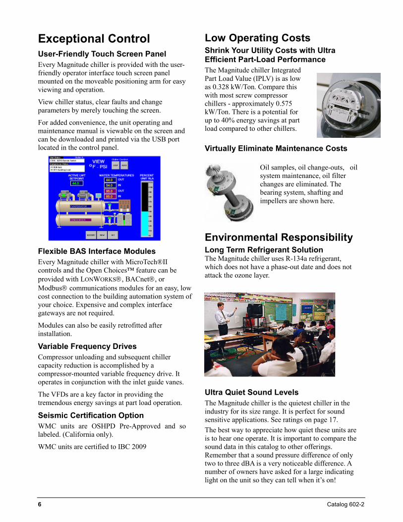
Exceptional Control User-Friendly Touch Screen Panel Every Magnitude chiller is provided with the user-friendly operator interface touch screen panel mounted on the moveable positioning arm for easy viewing and operation.
View chiller status, clear faults and change parameters by merely touching the screen.
For added convenience, the unit operating and maintenance manual is viewable on the screen and can be downloaded and printed via the USB port located in the control panel.
Flexible BAS Interface Modules Every Magnitude chiller with MicroTech®II controls and the Open Choices™ feature can be provided with LONWORKS, BACnet, or Modbus communications modules for an easy, low cost connection to the building automation system of your choice. Expensive and complex interface gateways are not required.
Modules can also be easily retrofitted after installation.
Variable Frequency Drives Compressor unloading and subsequent chiller capacity reduction is accomplished by a compressor-mounted variable frequency drive. It operates in conjunction with the inlet guide vanes.
The VFDs are a key factor in providing the tremendous energy savings at part load operation.
Seismic Certification Option WMC units are OSHPD Pre-Approved and so labeled. (California only).
WMC units are certified to IBC 2009
Low Operating Costs Shrink Your Utility Costs with Ultra Efficient Part-Load Performance The Magnitude chiller Integrated Part Load Value (IPLV) is as low as 0.328 kW/Ton. Compare this with most screw compressor chillers - approximately 0.575 kW/Ton. There is a potential for up to 40% energy savings at part load compared to other chillers.
Virtually Eliminate Maintenance Costs
Oil samples, oil change-outs, oil system maintenance, oil filter changes are eliminated. The bearing system, shafting and impellers are shown here.
Environmental Responsibility Long Term Refrigerant Solution The Magnitude chiller uses R-134a refrigerant, which does not have a phase-out date and does not attack the ozone layer.
Ultra Quiet Sound Levels The Magnitude chiller is the quietest chiller in the industry for its size range. It is perfect for sound sensitive applications. See ratings on page 17. The best way to appreciate how quiet these units are is to hear one operate. It is important to compare the sound data in this catalog to other offerings. Remember that a sound pressure difference of only two to three dBA is a very noticeable difference. A number of owners have asked for a large indicating light on the unit so they can tell when it’s on!
Catalog 602-2 7
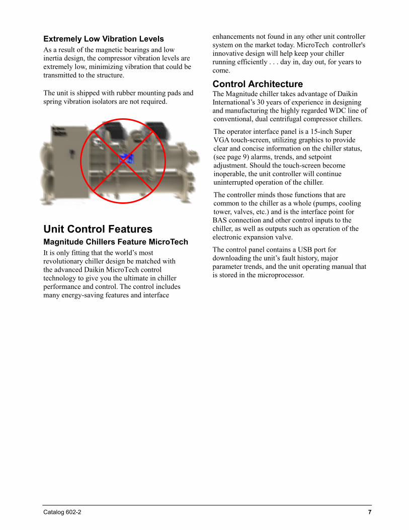
Extremely Low Vibration Levels As a result of the magnetic bearings and low inertia design, the compressor vibration levels are extremely low, minimizing vibration that could be transmitted to the structure.
The unit is shipped with rubber mounting pads and spring vibration isolators are not required.
Unit Control Features Magnitude Chillers Feature MicroTech It is only fitting that the world’s most revolutionary chiller design be matched with the advanced Daikin MicroTech control technology to give you the ultimate in chiller performance and control. The control includes many energy-saving features and interface
enhancements not found in any other unit controller system on the market today. MicroTech controller's innovative design will help keep your chiller running efficiently . . . day in, day out, for years to come.
Control Architecture The Magnitude chiller takes advantage of Daikin International’s 30 years of experience in designing and manufacturing the highly regarded WDC line of conventional, dual centrifugal compressor chillers.
The operator interface panel is a 15-inch Super VGA touch-screen, utilizing graphics to provide clear and concise information on the chiller status, (see page 9) alarms, trends, and setpoint adjustment. Should the touch-screen become inoperable, the unit controller will continue uninterrupted operation of the chiller.
The controller minds those functions that are common to the chiller as a whole (pumps, cooling tower, valves, etc.) and is the interface point for BAS connection and other control inputs to the chiller, as well as outputs such as operation of the electronic expansion valve.
The control panel contains a USB port for downloading the unit’s fault history, major parameter trends, and the unit operating manual that is stored in the microprocessor.
8 Catalog 602-2
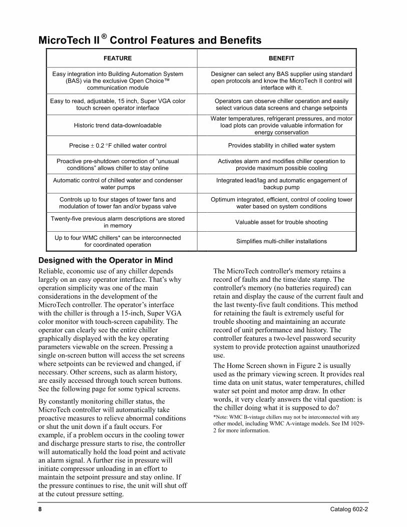
MicroTech II ® Control Features and Benefits FEATURE BENEFIT
Easy integration into Building Automation System (BAS) via the exclusive Open Choice™
communication module
Designer can select any BAS supplier using standard open protocols and know the MicroTech II control will
interface with it.
Easy to read, adjustable, 15 inch, Super VGA color touch screen operator interface Operators can observe chiller operation and easily
select various data screens and change setpoints
Historic trend data-downloadable Water temperatures, refrigerant pressures, and motor
load plots can provide valuable information for energy conservation
Precise ± 0.2 °F chilled water control Provides stability in chilled water system
Proactive pre-shutdown correction of “unusual conditions” allows chiller to stay online Activates alarm and modifies chiller operation to
provide maximum possible cooling
Automatic control of chilled water and condenser water pumps Integrated lead/lag and automatic engagement of
backup pump
Controls up to four stages of tower fans and modulation of tower fan and/or bypass valve Optimum integrated, efficient, control of cooling tower
water based on system conditions
Twenty-five previous alarm descriptions are stored in memory Valuable asset for trouble shooting
Up to four WMC chillers* can be interconnected for coordinated operation Simplifies multi-chiller installations
Designed with the Operator in MindReliable, economic use of any chiller depends largely on an easy operator interface. That’s why operation simplicity was one of the main considerations in the development of the MicroTech controller. The operator’s interface with the chiller is through a 15-inch, Super VGA color monitor with touch-screen capability. The operator can clearly see the entire chiller graphically displayed with the key operating parameters viewable on the screen. Pressing a single on-screen button will access the set screens where setpoints can be reviewed and changed, if necessary. Other screens, such as alarm history, are easily accessed through touch screen buttons. See the following page for some typical screens.
By constantly monitoring chiller status, the MicroTech controller will automatically take proactive measures to relieve abnormal conditions or shut the unit down if a fault occurs. For example, if a problem occurs in the cooling tower and discharge pressure starts to rise, the controller will automatically hold the load point and activate an alarm signal. A further rise in pressure will initiate compressor unloading in an effort to maintain the setpoint pressure and stay online. If the pressure continues to rise, the unit will shut off at the cutout pressure setting.
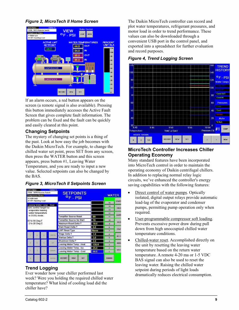
The MicroTech controller's memory retains a record of faults and the time/date stamp. The controller's memory (no batteries required) can retain and display the cause of the current fault and the last twenty-five fault conditions. This method for retaining the fault is extremely useful for trouble shooting and maintaining an accurate record of unit performance and history. The controller features a two-level password security system to provide protection against unauthorized use. The Home Screen shown in Figure 2 is usually used as the primary viewing screen. It provides real time data on unit status, water temperatures, chilled water set point and motor amp draw. In other words, it very clearly answers the vital question: is the chiller doing what it is supposed to do? *Note: WMC B-vintage chillers may not be interconnected with any other model, including WMC A-vintage models. See IM 1029-2 for more information.
Catalog 602-2 9
Figure 2, MicroTech II Home Screen
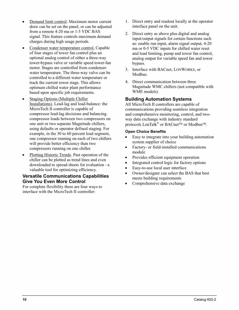
If an alarm occurs, a red button appears on the screen (a remote signal is also available). Pressing this button immediately accesses the Active Fault Screen that gives complete fault information. The problem can be fixed and the fault can be quickly and easily cleared at this point. Changing Setpoints The mystery of changing set points is a thing of the past. Look at how easy the job becomes with the Daikin MicroTech. For example, to change the chilled water set point, press SET from any screen, then press the WATER button and this screen appears, press button #1, Leaving Water Temperature, and you are ready to input a new value. Selected setpoints can also be changed by the BAS.
Figure 3, MicroTech II Setpoints Screen
Trend Logging Ever wonder how your chiller performed last week? Were you holding the required chilled water temperature? What kind of cooling load did the chiller have?
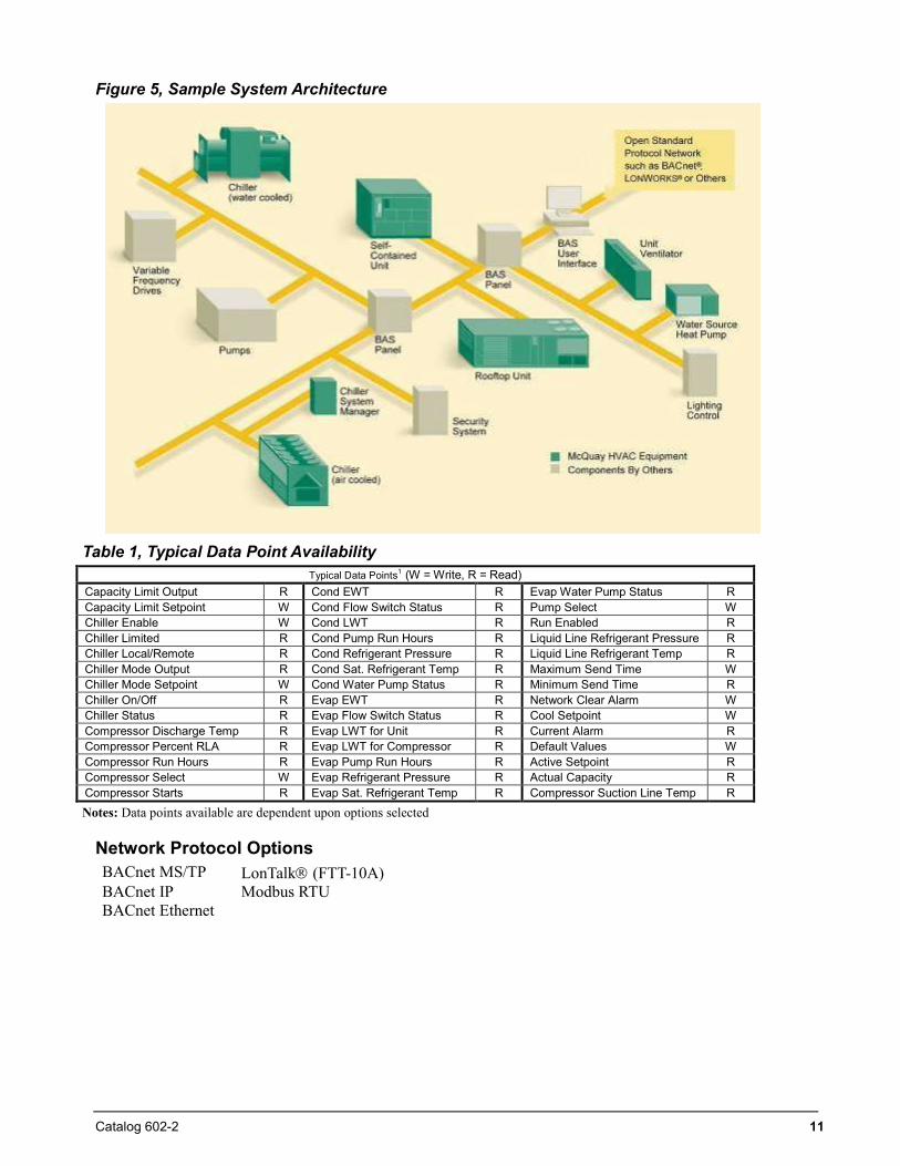
The Daikin MicroTech controller can record and plot water temperatures, refrigerant pressures, and motor load in order to trend performance. These values can also be downloaded through a convenient USB port in the control panel, and exported into a spreadsheet for further evaluation and record purposes.
Figure 4, Trend Logging Screen
MicroTech Controller Increases Chiller Operating Economy Many standard features have been incorporated into MicroTech control in order to maintain the operating economy of Daikin centrifugal chillers. In addition to replacing normal relay logic circuits, we’ve enhanced the controller's energy saving capabilities with the following features:
• Direct control of water pumps. Opticallyisolated, digital output relays provide automaticlead-lag of the evaporator and condenserpumps, permitting pump operation only whenrequired.
• User-programmable compressor soft loading.Prevents excessive power draw during pulldown from high unoccupied chilled watertemperature conditions.
• Chilled-water reset. Accomplished directly onthe unit by resetting the leaving watertemperature based on the return watertemperature. A remote 4-20 ma or 1-5 VDCBAS signal can also be used to reset theleaving water. Raising the chilled watersetpoint during periods of light loadsdramatically reduces electrical consumption.
10 Catalog 602-2
• Demand limit control. Maximum motor current draw can be set on the panel, or can be adjusted from a remote 4-20 ma or 1-5 VDC BAS signal. This feature controls maximum demand charges during high usage periods.
• Condenser water temperature control. Capable of four stages of tower fan control plus an optional analog control of either a three-way tower-bypass valve or variable speed tower-fan motor. Stages are controlled from condenser-water temperature. The three-way valve can be controlled to a different water temperature or track the current tower stage. This allows optimum chilled water plant performance based upon specific job requirements.
• Staging Options (Multiple Chiller Installations). Lead-lag and load-balance: the MicroTech II controller is capable of compressor lead-lag decisions and balancing compressor loads between two compressors on one unit or two separate Magnitude chillers, using defaults or operator defined staging. For example, in the 30 to 60 percent load segment, one compressor running on each of two chillers will provide better efficiency than two compressors running on one chiller.
• Plotting Historic Trends. Past operation of the chiller can be plotted as trend lines and even downloaded to spread sheets for evaluation - a valuable tool for optimizing efficiency.
Versatile Communications Capabilities Give You Even More Control For complete flexibility there are four ways to interface with the MicroTech II controller:
1. Direct entry and readout locally at the operator interface panel on the unit.
2. Direct entry as above plus digital and analog input/output signals for certain functions such as: enable run input, alarm signal output, 4-20 ma or 0-5 VDC inputs for chilled water reset and load limiting, pump and tower fan control, analog output for variable speed fan and tower bypass.
3. Interface with BACnet, LONWORKS, or Modbus.
4. Direct communication between three Magnitude WMC chillers (not compatible with WME models).
Building Automation Systems All MicroTech II controllers are capable of communications providing seamless integration and comprehensive monitoring, control, and two-way data exchange with industry standard protocols LonTalk® or BACnet or Modbus. Open Choice Benefits • Easy to integrate into your building automation
system supplier of choice • Factory- or field-installed communications
module • Provides efficient equipment operation • Integrated control logic for factory options • Easy-to-use local user interface • Owner/designer can select the BAS that best
meets building requirements • Comprehensive data exchange
Catalog 602-2 11
Figure 5, Sample System Architecture
Table 1, Typical Data Point Availability
Typical Data Points1 (W = Write, R = Read) Capacity Limit Output R Cond EWT R Evap Water Pump Status R Capacity Limit Setpoint W Cond Flow Switch Status R Pump Select W Chiller Enable W Cond LWT R Run Enabled R Chiller Limited R Cond Pump Run Hours R Liquid Line Refrigerant Pressure R Chiller Local/Remote R Cond Refrigerant Pressure R Liquid Line Refrigerant Temp R Chiller Mode Output R Cond Sat. Refrigerant Temp R Maximum Send Time W Chiller Mode Setpoint W Cond Water Pump Status R Minimum Send Time R Chiller On/Off R Evap EWT R Network Clear Alarm W Chiller Status R Evap Flow Switch Status R Cool Setpoint W Compressor Discharge Temp R Evap LWT for Unit R Current Alarm R Compressor Percent RLA R Evap LWT for Compressor R Default Values W Compressor Run Hours R Evap Pump Run Hours R Active Setpoint R Compressor Select W Evap Refrigerant Pressure R Actual Capacity R Compressor Starts R Evap Sat. Refrigerant Temp R Compressor Suction Line Temp R
Notes: Data points available are dependent upon options selected
Network Protocol Options BACnet MS/TP LonTalk (FTT-10A) BACnet IP Modbus RTU BACnet Ethernet
12 Catalog 602-2
Unit Design Features Variable Frequency Drive Efficiency: The standard variable frequency drive is a technology that has been used for decades to control motor speed on a wide variety of motor-drive applications. When applied to centrifugal compressor motors, significant gains in part load performance can be realized. The improvement in efficiency and reduction of annual energy cost is maximized when there are long periods of part load operation, combined with low compressor lift (lower condenser water temperatures). The attributes of VFD and the compressor technology produces one of the industry's most efficient chiller based on the all-important IPLV value. See “IPLV/NPLV Defined” on page 14 for details on the AHRI IPLV efficiency rating. Starting Inrush: The use of a VFD on centrifugal chillers also provides an excellent method of reducing motor starting inrush-even better than "solid state" starters. Starting current can be closely controlled since both the frequency and voltage are regulated. This can be an important benefit to a building's electrical distribution system. The low inrush feature, combined with two one-half size compressors having a staggered start, is particularly attractive where chillers will be asked to operate on emergency generators. Since inrush has much to do with sizing the generators, much smaller generators can be used. Optional Harmonic Filter An optional field-mounted harmonic filter is available. See page 40 for details.
HFC-134a Daikin Positive Pressure Design:
• No Purge• No Vacuum Prevention System• No Contaminants
HFC-134a operates above atmospheric pressure in the entire refrigerant circuit and at normal temperatures. All Daikin centrifugal chillers use a positive pressure refrigerant, with the following benefits: • No absorption of impurities into the refrigerant
circuit• No breakdown of motor insulation, refrigerant
or lubricant• No increase in operating cost due to
displacement of heat transfer surface by non-condensables
• No crevice corrosion and tube failure due tomoisture in the system
• No annual service expense to maintain andrebuild purge unit
• No abnormal annual service expense for oil,filter, and refrigerant replacement
• No periodic emissions of refrigerant into theatmosphere
Heat Exchangers Daikin Magnitude chillers are equipped with high performance heat exchangers. The unique design greatly increases heat transfer and reduces unit footprint and refrigerant charge. Vessels are designed, constructed and tested in accordance with ASME Section VIII, ASHRAE Standard 15 requirements and TEMA recommendations. The replaceable water tubes are internally rifled and externally enhanced copper, and are mechanically bonded to steel tube sheets. Standard tubes are 0.025-inch wall thickness. Consult factory for other options. Vessels are available for 1, 2 or 3 pass water flow. A 3/4" or 1-1/2 thick layer of vinyl/nitrate polymer evaporator insulation is optional. All seams are glued to form an effective vapor barrier. Detailed information on the insulation can be found under “Physical Data” on page 27.
Pumpdown Pumpout systems provide a means to collect and contain the refrigerant charge without loss when access to internal chiller components is required for service.
Daikin condensers and evaporators are sized to hold the entire unit refrigerant charge when not more than 90% full and at 90°F (32°C) ambient temperature. They are equipped with valves in the compressor discharge lines, suction lines, and in the liquid line. These valves, coupled with the vessel design, satisfy the stringent requirements of the U.S. Department of Transportation for refrigerant shipping containers, as well as ASME vessel codes. When service is required, the refrigerant charge can be pumped down into either the condenser or evaporator by compressor operation and use of a refrigerant transfer unit.
Catalog 602-2 13
Elimination of the cost and space requirements of an external pumpout system on most jobs is a major Daikin advantage.
Electronic Expansion Valve Controlled refrigerant flow over the entire capacity range saves energy and dollars. Cooling loads and condenser water temperatures can change constantly. On Magnitude chillers, a modern electronic expansion valve meters refrigerant flow in direct response to the unit controller input, which looks at unit kW and lift (discharge minus suction pressure) to set the valve position. The controller then balances suction superheat and liquid subcooling to reach the optimum efficiency, regardless of changing load or condensing temperatures. In doing so, full utilization of compressor, evaporator, and condenser efficiency over the entire operating range is achieved.
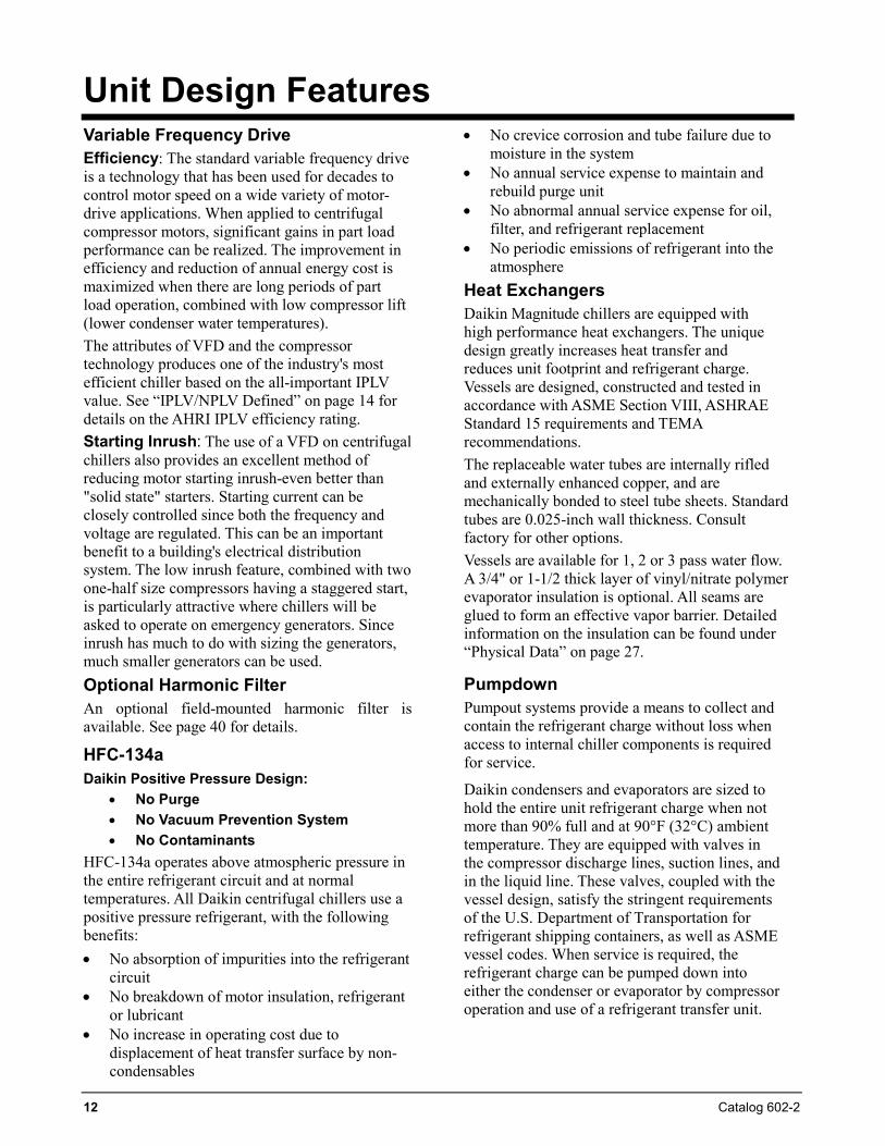
Flow Switch All chiller units must be provided with flow switches for the evaporator and condenser. Daikin furnishes factory-installed and wired, thermal dispersion-type flow switches as standard equipment on Magnitude chillers. This eliminates the expense of field mounting and wiring conventional paddle or differential pressure switches.
The flow switches prevent the unit from starting without sufficient water flow through the vessels. They also serve to shut down the unit in the event that water flow is interrupted to
guard against evaporator freeze-up or excessive discharge pressure.
Additionally, for a higher margin of protection, normally open auxiliary contacts in the pump starters can be wired in series with the flow switches as shown in the Field Wiring Diagram.
Optional Certified Test A factory engineer oversees the testing, certifies the accuracy of the computerized results, and translates the test data onto an easy-to-read spreadsheet. The tests are run to AHRI tolerance of capacity and power. 50 Hertz units are tested using an on-site 50 Hertz generator.
Optional Witness Test A factory engineer oversees the testing in the presence of the customer or their designate and translates the test data onto an easy-to-read spreadsheet. Tests are run to AHRI tolerances of capacity and power. 50 Hertz units are tested using an on-site 50 Hertz generator.
Daikin Factory Service Startup All Daikin centrifugal chillers are commissioned by local Daikin Factory Service personnel or by authorized Daikin startup technicians. This procedure helps assure that proper starting and checkout procedures are employed and helps speed up the commissioning process.
Part Load Efficiency According to ASHRAE, chillers usually spend 99% of their operating hours under part load conditions and most of this time at less than 60% of design capacity. One compressor of a dual chiller operates with the full heat transfer surface of the entire unit. For example, one 75-ton compressor on a 150-ton dual chiller utilizes 150 tons of evaporator and condenser surface. This results in very high unit efficiency and also increases the compressor’s capacity. The inclusion of VFDs, as standard, to the dual compressor chiller can produce astonishing AHRI Certified IPLVs, as low as 0.328 kW/ton. Specific selections can vary from this example.
Compliance with ASHRAE Std. 90.1 With the Magnitude chiller capacity range of 145 to 400 tons, they fall into three ASHRAE Std. 90.1 efficiency groups and revisions.
14 Catalog 602-2
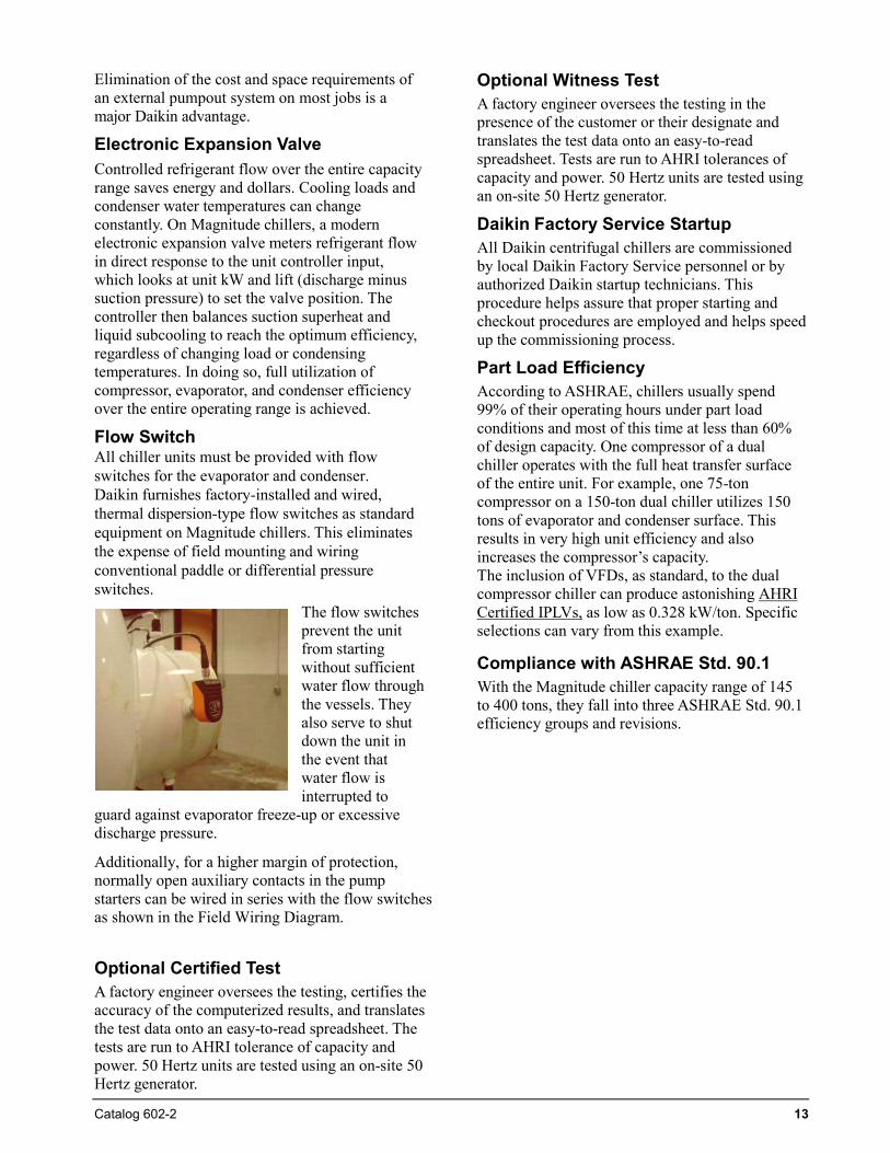
Table 2, ASHRAE 90.1 Requirements (kW/ton)
Std. 90.1 Capacity Range
Pre 2010 Starting in 2010
Full Load
IPLV Path A Path B
Full Load- IPLV Full
Load- IPLV
< 150 Tons 0.703 0.669 0.634 0.596 0.639 0.450 ≥ 150 Tons < 300 Tons
0.634 0.596 0.634 0.596 0.639 0.450
≥ 300 Tons < 600 Tons
0.576 0.549 0.576 0.549 0.600 0.400
NOTE: Beginning in 2010, the 90.1 efficiency requirements have been divided into two groups, designated as Path A and Path B. Path B is a new category created for units with VFD compressor drives that by nature have superior part-load efficiencies. WMC Magnitude chillers, with their built-in VFDs, fall into Path B.
The Path B IPLV values for 2010 are about 30 percent less than the 2007 equivalent values. Also beginning in 2010, the minimum efficiency values are formula derived instead tabular so that they can take flows and temperatures other than AHRI standard into account.
AHRI Certification Daikin has an on-going commitment to supply chillers that perform as specified. To this extent, Daikin centrifugal chillers are part of the AHRI Certification Program. On-going performance verification of chiller capacity and power input plus AHRI certified computerized selection output provide the owner with specified performance in accordance with the latest version of AHRI Standard 550/590.
All chillers that fall within the scope of the certification program have an AHRI certification label at no cost to the owner. Equipment covered by the AHRI certification program includes all water-cooled centrifugal and screw water chilling packages rated up to 2500 tons (8800 kW) at AHRI standard rating conditions, hermetic or open drive, with electric driven motor not exceeding 5000 volts, and cooling water (not glycol).
Published certified ratings verified through testing by AHRI include:
• Capacity, tons (kW)• Power, kW/ton (COP)• Pressure drops, ft. of water (kPa)• Integrated Part Load Value (IPLV) or Non-
Standard Part Load Value (NPLV)
The AHRI Standard 550/590 for Centrifugal or Screw Water-Chilling Packages and associated manuals define certification and testing procedures
and performance tolerances of all units that fall within the application rating conditions.
Leaving chilled water temp.: 40°F to 48°F (44°F standard) Entering condenser water temp.: 60°F to 95°F Leaving chilled water temp.: 44°F Evap. waterside field fouling allowance: 0.0001 Chilled water flow rate: 2.4 gpm/ton Entering condenser water temp.: 85°F Condenser waterside field fouling allowance:
0.00025 Condenser water flow rate: 3.0 gpm/ton IPLV/NPLV Defined
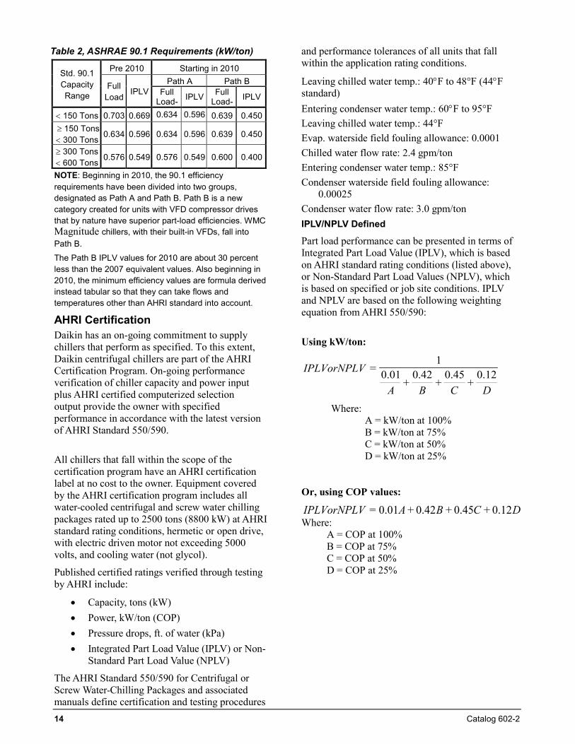
Part load performance can be presented in terms of Integrated Part Load Value (IPLV), which is based on AHRI standard rating conditions (listed above), or Non-Standard Part Load Values (NPLV), which is based on specified or job site conditions. IPLV and NPLV are based on the following weighting equation from AHRI 550/590:
Using kW/ton:
DCBA
IPLVorNPLV 12.0+
45.0+
42.0+
01.01
=
Where: A = kW/ton at 100% B = kW/ton at 75% C = kW/ton at 50% D = kW/ton at 25%
Or, using COP values:
DCBAIPLVorNPLV 12.0+45.0+42.0+01.0=Where:
A = COP at 100% B = COP at 75% C = COP at 50% D = COP at 25%
Catalog 602-2 15
Weighting The percent of annual hours of operation at the four load points are as follows:
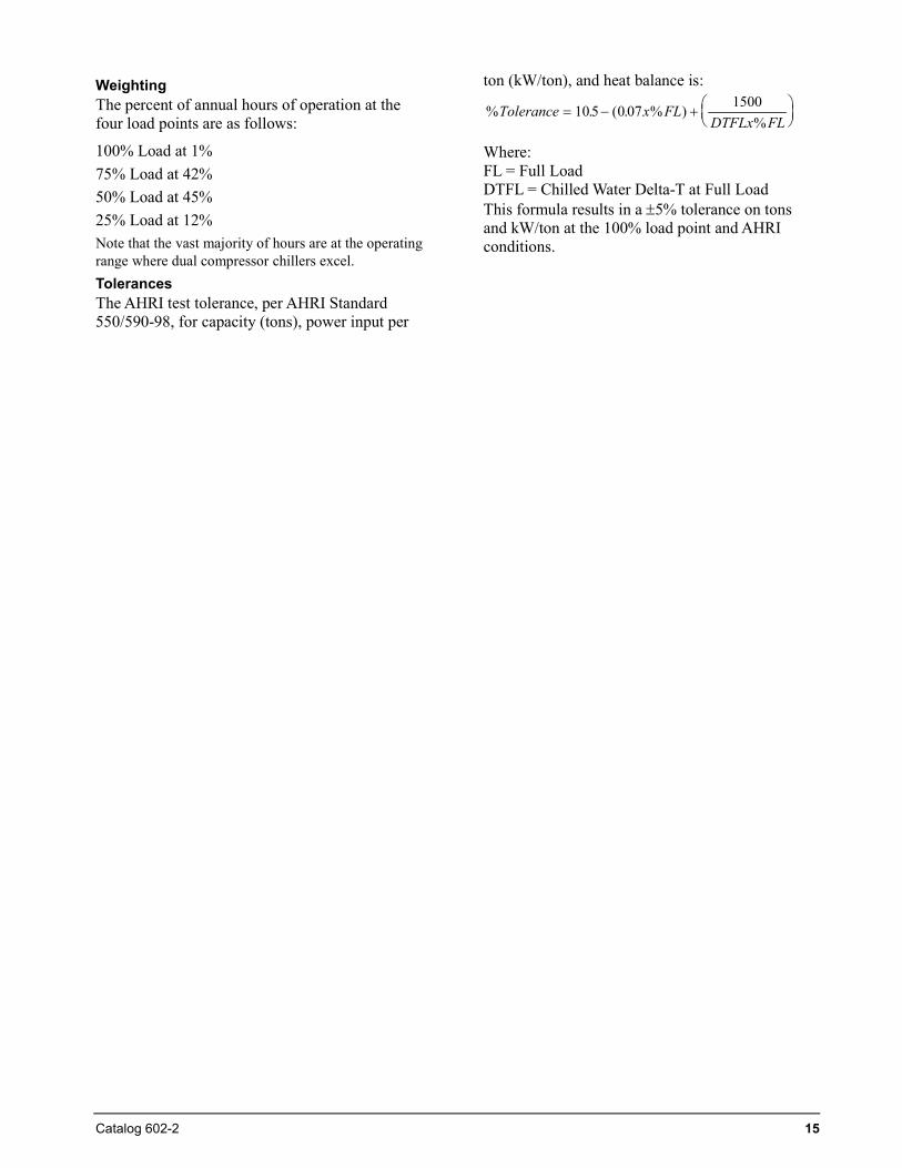
100% Load at 1% 75% Load at 42% 50% Load at 45% 25% Load at 12% Note that the vast majority of hours are at the operating range where dual compressor chillers excel. Tolerances The AHRI test tolerance, per AHRI Standard 550/590-98, for capacity (tons), power input per
ton (kW/ton), and heat balance is:
% . ( . % )%
Tolerance x FLDTFLx FL
= − +
10 5 0 07 1500
Where: FL = Full Load DTFL = Chilled Water Delta-T at Full Load This formula results in a ±5% tolerance on tons and kW/ton at the 100% load point and AHRI conditions.
16 Catalog 602-2
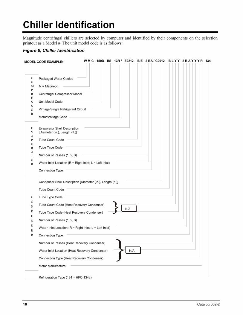
Chiller Identification Magnitude centrifugal chillers are selected by computer and identified by their components on the selection printout as a Model #. The unit model code is as follows:
Figure 6, Chiller Identification MODEL CODE EXAMPLE: W M C - 150D - BS - 13R / E2212 - B E - 2 RA / C2012 - B L Y Y - 2 R A Y Y Y R 134
Packaged Water Cooled
M = Magnetic
Centrifugal Compressor Model
Unit Model Code
Vintage/Single Refrigerant Circuit
Motor/Voltage Code
Evaporator Shell Description [Diameter (in.), Length (ft.)]
Tube Count Code
Tube Type Code
Number of Passes (1, 2, 3)
Water Inlet Location (R = Right Inlet; L = Left Inlet)
Connection Type
Condenser Shell Description [Diameter (in.), Length (ft.)]
Tube Count Code
Tube Type Code
Tube Count Code (Heat Recovery Condenser)
Tube Type Code (Heat Recovery Condenser)
Number of Passes (1, 2, 3)
Wate r Inlet Location (R = Right Inlet; L = Left Inlet)
Connection Type
Number of Passes (Heat Recovery Condenser)
Water Inlet Location (Heat Recovery Condenser)
Connection Type (Heat Recovery Condenser)
Motor Manufacturer
Refrigeration Type (134 = HFC-134a)
CONDENSER
N/A
N/A
EVAPORATOR
COMPRES SOR
Catalog 602-2 17
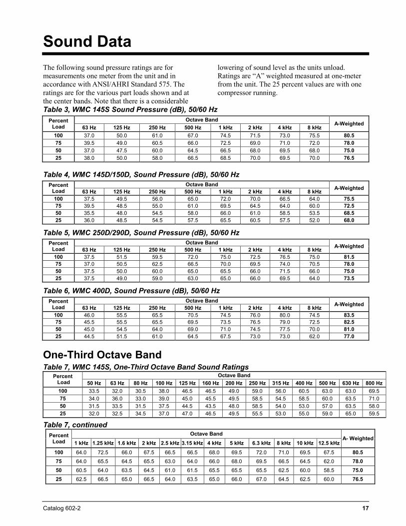
Sound Data The following sound pressure ratings are for measurements one meter from the unit and in accordance with ANSI/AHRI Standard 575. The ratings are for the various part loads shown and at the center bands. Note that there is a considerable
lowering of sound level as the units unload. Ratings are “A” weighted measured at one-meter from the unit. The 25 percent values are with one compressor running.
Table 3, WMC 145S Sound Pressure (dB), 50/60 Hz Percent
Load Octave Band
A-Weighted 63 Hz 125 Hz 250 Hz 500 Hz 1 kHz 2 kHz 4 kHz 8 kHz
100 37.0 50.0 61.0 67.0 74.5 71.5 73.0 75.5 80.5 75 39.5 49.0 60.5 66.0 72.5 69.0 71.0 72.0 78.0 50 37.0 47.5 60.0 64.5 66.5 68.0 69.5 68.0 75.0 25 38.0 50.0 58.0 66.5 68.5 70.0 69.5 70.0 76.5
Table 4, WMC 145D/150D, Sound Pressure (dB), 50/60 Hz Percent
Load Octave Band A-Weighted 63 Hz 125 Hz 250 Hz 500 Hz 1 kHz 2 kHz 4 kHz 8 kHz
100 37.5 49.5 56.0 65.0 72.0 70.0 66.5 64.0 75.5 75 39.5 48.5 55.0 61.0 69.5 64.5 64.0 60.0 72.5 50 35.5 48.0 54.5 58.0 66.0 61.0 58.5 53.5 68.5 25 36.0 48.5 54.5 57.5 65.5 60.5 57.5 52.0 68.0
Table 5, WMC 250D/290D, Sound Pressure (dB), 50/60 Hz Percent
Load Octave Band A-Weighted 63 Hz 125 Hz 250 Hz 500 Hz 1 kHz 2 kHz 4 kHz 8 kHz
100 37.5 51.5 59.5 72.0 75.0 72.5 76.5 75.0 81.5 75 37.0 50.5 62.5 66.5 70.0 69.5 74.0 70.5 78.0 50 37.5 50.0 60.0 65.0 65.5 66.0 71.5 66.0 75.0 25 37.5 49.0 59.0 63.0 65.0 66.0 69.5 64.0 73.5
Table 6, WMC 400D, Sound Pressure (dB), 50/60 Hz Percent
Load Octave Band A-Weighted 63 Hz 125 Hz 250 Hz 500 Hz 1 kHz 2 kHz 4 kHz 8 kHz
100 46.0 55.5 65.5 70.5 74.5 76.0 80.0 74.5 83.5 75 45.5 55.5 65.5 69.5 73.5 76.5 79.0 72.5 82.5 50 45.0 54.5 64.0 69.0 71.0 74.5 77.5 70.0 81.0 25 44.5 51.5 61.0 64.5 67.5 73.0 73.0 62.0 77.0
One-Third Octave Band Table 7, WMC 145S, One-Third Octave Band Sound Ratings
Percent Load
Octave Band 50 Hz 63 Hz 80 Hz 100 Hz 125 Hz 160 Hz 200 Hz 250 Hz 315 Hz 400 Hz 500 Hz 630 Hz 800 Hz
100 33.5 32.0 30.5 38.0 46.5 46.5 49.0 59.0 56.0 60.5 63.0 63.0 69.5 75 34.0 36.0 33.0 39.0 45.0 45.5 49.5 58.5 54.5 58.5 60.0 63.5 71.0 50 31.5 33.5 31.5 37.5 44.5 43.5 48.0 58.5 54.0 53.0 57.0 63.5 58.0 25 32.0 32.5 34.5 37.0 47.0 46.5 49.5 55.5 53.0 55.0 59.0 65.0 59.5
Table 7, continued Percent
Load Octave Band
A- Weighted 1 kHz 1.25 kHz 1.6 kHz 2 kHz 2.5 kHz 3.15 kHz 4 kHz 5 kHz 6.3 kHz 8 kHz 10 kHz 12.5 kHz
100 64.0 72.5 66.0 67.5 66.5 66.5 68.0 69.5 72.0 71.0 69.5 67.5 80.5 75 64.0 65.5 64.5 65.5 63.0 64.0 66.0 68.0 69.5 66.5 64.5 62.0 78.0 50 60.5 64.0 63.5 64.5 61.0 61.5 65.5 65.5 65.5 62.5 60.0 58.5 75.0 25 62.5 66.5 65.0 66.5 64.0 63.5 65.0 66.0 67.0 64.5 62.5 60.0 76.5
18 Catalog 602-2
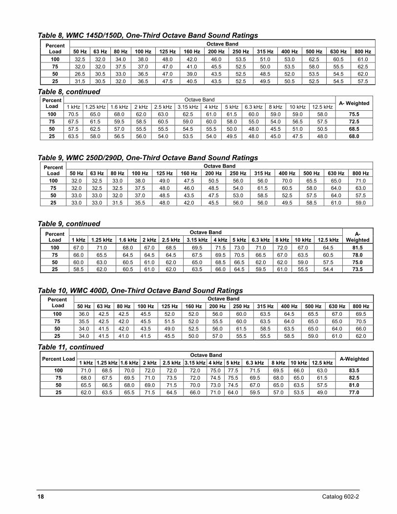
Table 8, WMC 145D/150D, One-Third Octave Band Sound Ratings Percent
Load Octave Band
50 Hz 63 Hz 80 Hz 100 Hz 125 Hz 160 Hz 200 Hz 250 Hz 315 Hz 400 Hz 500 Hz 630 Hz 800 Hz 100 32.5 32.0 34.0 38.0 48.0 42.0 46.0 53.5 51.0 53.0 62.5 60.5 61.0 75 32.0 32.0 37.5 37.0 47.0 41.0 45.5 52.5 50.0 53.5 58.0 55.5 62.5 50 26.5 30.5 33.0 36.5 47.0 39.0 43.5 52.5 48.5 52.0 53.5 54.5 62.0 25 31.5 30.5 32.0 36.5 47.5 40.5 43.5 52.5 49.5 50.5 52.5 54.5 57.5
Table 8, continued Percent
Load Octave Band A- Weighted
1 kHz 1.25 kHz 1.6 kHz 2 kHz 2.5 kHz 3.15 kHz 4 kHz 5 kHz 6.3 kHz 8 kHz 10 kHz 12.5 kHz 100 70.5 65.0 68.0 62.0 63.0 62.5 61.0 61.5 60.0 59.0 59.0 58.0 75.5 75 67.5 61.5 59.5 58.5 60.5 59.0 60.0 58.0 55.0 54.0 56.5 57.5 72.5 50 57.5 62.5 57.0 55.5 55.5 54.5 55.5 50.0 48.0 45.5 51.0 50.5 68.5 25 63.5 58.0 56.5 56.0 54.0 53.5 54.0 49.5 48.0 45.0 47.5 48.0 68.0
Table 9, WMC 250D/290D, One-Third Octave Band Sound Ratings
Percent Load
Octave Band 50 Hz 63 Hz 80 Hz 100 Hz 125 Hz 160 Hz 200 Hz 250 Hz 315 Hz 400 Hz 500 Hz 630 Hz 800 Hz
100 32.0 32.5 33.0 38.0 49.0 47.5 50.5 56.0 56.0 70.0 65.5 65.0 71.0 75 32.0 32.5 32.5 37.5 48.0 46.0 48.5 54.0 61.5 60.5 58.0 64.0 63.0 50 33.0 33.0 32.0 37.0 48.5 43.5 47.5 53.0 58.5 52.5 57.5 64.0 57.5 25 33.0 33.0 31.5 35.5 48.0 42.0 45.5 56.0 56.0 49.5 58.5 61.0 59.0
Table 9, continued
Percent Load
Octave Band A- Weighted 1 kHz 1.25 kHz 1.6 kHz 2 kHz 2.5 kHz 3.15 kHz 4 kHz 5 kHz 6.3 kHz 8 kHz 10 kHz 12.5 kHz
100 67.0 71.0 68.0 67.0 68.5 69.5 71.5 73.0 71.0 72.0 67.0 64.5 81.5 75 66.0 65.5 64.5 64.5 64.5 67.5 69.5 70.5 66.5 67.0 63.5 60.5 78.0 50 60.0 63.0 60.5 61.0 62.0 65.0 68.5 66.5 62.0 62.0 59.0 57.5 75.0 25 58.5 62.0 60.5 61.0 62.0 63.5 66.0 64.5 59.5 61.0 55.5 54.4 73.5
Table 10, WMC 400D, One-Third Octave Band Sound Ratings
Percent Load
Octave Band 50 Hz 63 Hz 80 Hz 100 Hz 125 Hz 160 Hz 200 Hz 250 Hz 315 Hz 400 Hz 500 Hz 630 Hz 800 Hz
100 36.0 42.5 42.5 45.5 52.0 52.0 56.0 60.0 63.5 64.5 65.5 67.0 69.5 75 35.5 42.5 42.0 45.5 51.5 52.0 55.5 60.0 63.5 64.0 65.0 65.0 70.5 50 34.0 41.5 42.0 43.5 49.0 52.5 56.0 61.5 58.5 63.5 65.0 64.0 66.0 25 34.0 41.5 41.0 41.5 45.5 50.0 57.0 55.5 55.5 58.5 59.0 61.0 62.0
Table 11, continued Percent Load
Octave Band A-Weighted
1 kHz 1.25 kHz 1.6 kHz 2 kHz 2.5 kHz 3.15 kHz 4 kHz 5 kHz 6.3 kHz 8 kHz 10 kHz 12.5 kHz 100 71.0 68.5 70.0 72.0 72.0 72.0 75.0 77.5 71.5 69.5 66.0 63.0 83.5 75 68.0 67.5 69.5 71.0 73.5 72.0 74.5 75.5 69.5 68.0 65.0 61.5 82.5 50 65.5 66.5 68.0 69.0 71.5 70.0 73.0 74.5 67.0 65.0 63.5 57.5 81.0 25 62.0 63.5 65.5 71.5 64.5 66.0 71.0 64.0 59.5 57.0 53.5 49.0 77.0
Catalog 602-2 19
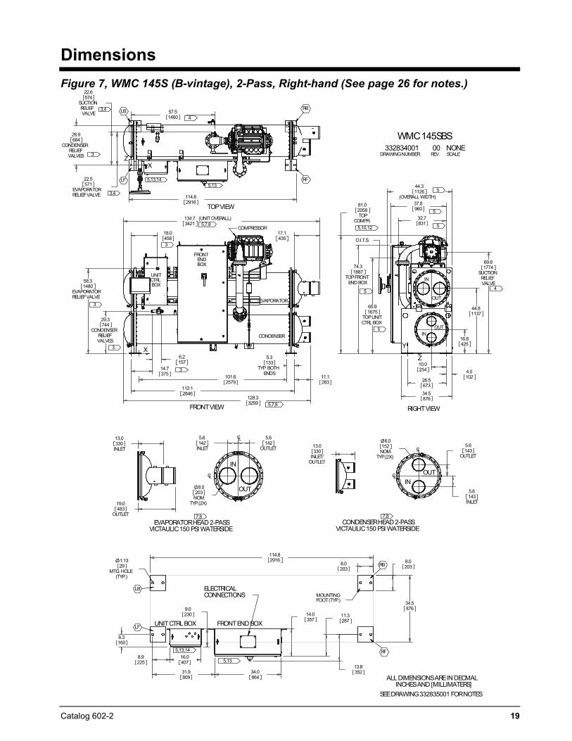
Dimensions Figure 7, WMC 145S (B-vintage), 2-Pass, Right-hand (See page 26 for notes.)
6.2157
14.7375
112.12846
101.62579
128.33259
5.3
TYP. BOTHENDS
133
29.3
CONDENSERRELIEFVALVES
744
58.3
EVAPORATORRELIEFVALVE
1480
134.7 (UNITOVERALL)3421
18.0458
11.1283
17.1435
FRONTENDBOX
UNITCTRLBOX
EVAPORATOR
CONDENSER
COMPRESSOR
FRONTVIEW
XY
5,7,8
3
3
3
3
114.82916
57.51460
22.5
EVAPORATORRELIEFVALVE
571
22.6
SUCTIONRELIEFVALVE
574
26.9
CONDENSERRELIEFVALVES
684
TOPVIEW
RB
RFLF
LB
ZX
4
3
3,4
3,45,13
5,13,14
5,7,8
4.010226.5
67334.5876
10.0254
32.7831
37.8960
44.3
(OVERALLWIDTH)1126
16.8425
44.81137
65.9
TOPUNITCTRLBOX
1675
74.3
TOPFRONTEND BOX
1887
81.0
TOPCOMPR.
2058
69.8
SUCTIONRELIEFVALVE
1774
O.I.T.S.
IN
INOUT
OUT
RIGHTVIEW
Y
Z
5
5
5,10,12
5 4
5
5
5.6
INLET142
5.6
OUTLET142
8.0
NOM.TYP.(2X)
203
EVAPORATORHEAD 2-PASSVICTAULIC150 PSI WATERSIDE
CL
CL
OUT
IN
7,8
13.0
INLET330
19.0
OUTLET483
5.6
OUTLET143
5.6
INLET143
6.0
NOM.TYP.(2X)
152
CONDENSERHEAD 2-PASSVICTAULIC150 PSI WATERSIDE
CL
CL
INOUT
7,8
13.0
INLET/OUTLET
330
11.3287
114.82916
34.5876
1.13
MTG. HOLE(TYP.)
29
6.3160
8.9225
16.0407
31.9809
34.0864
9.0230 14.0
357
13.8352
8.02038.0
203
MOUNTINGFOOT(TYP.)
ELECTRICALCONNECTIONS
FRONTEND BOXUNITCTRLBOX
ALLDIMENSIONSAREIN DECMALINCHESAND [MILLIMATERS]
SEEDRAWING332835001 FORNOTES
RB
LB
LF
RF5,13,14
5,13
WMC145SBS332834001 00 NONE
DRAWINGNUMBER REV. SCALE
20 Catalog 602-2
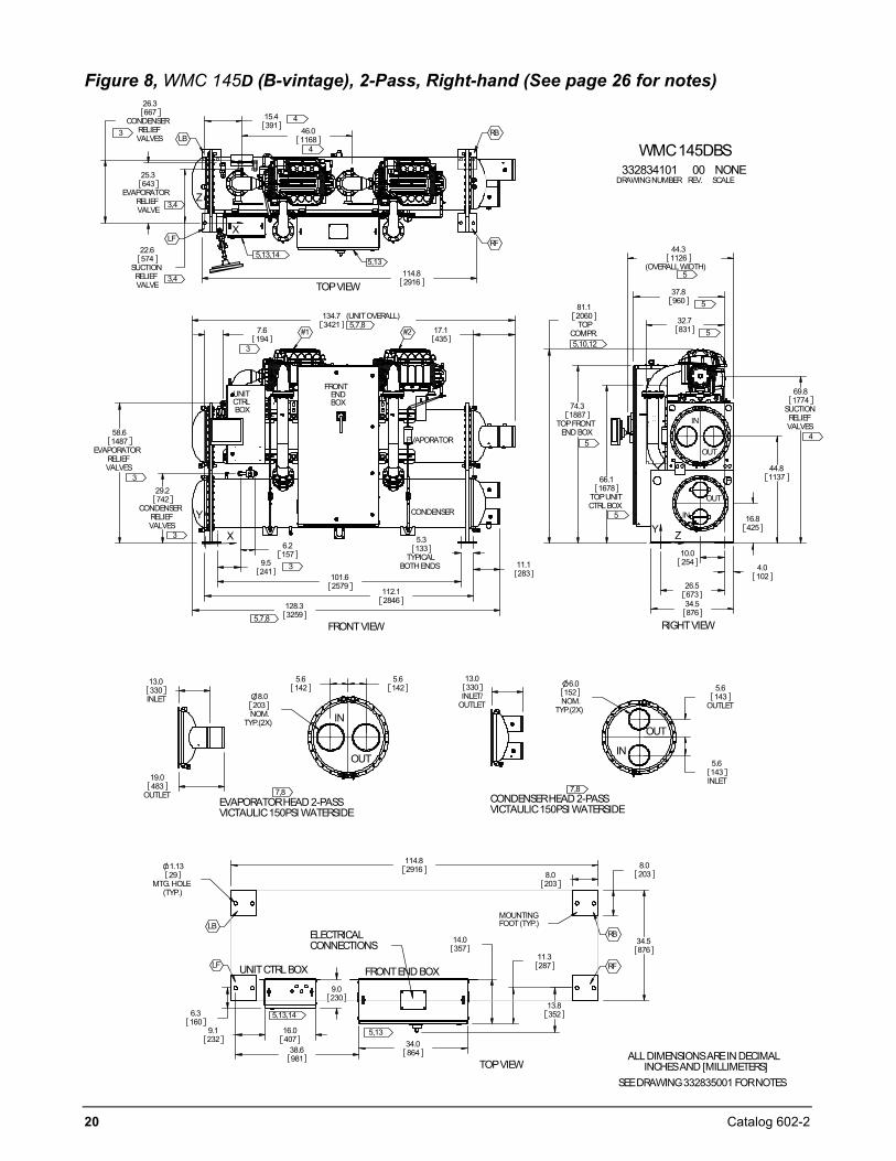
Figure 8, WMC 145D (B-vintage), 2-Pass, Right-hand (See page 26 for notes)
7.6194
6.2157
9.5241
101.62579
112.12846
5.3
TYPICALBOTH ENDS
133
128.33259
29.2
CONDENSERRELIEFVALVES
742
58.6
EVAPORATORRELIEFVALVES
1487
134.7 (UNITOVERALL)3421
17.1435
11.1283
UNITCTRLBOX
FRONTENDBOX
CONDENSER
EVAPORATOR
FRONTVIEW
#1 #2
3
3
3
3
5
5,7,8
Y
X
114.82916
15.4391
46.01168
22.6
SUCTIONRELIEFVALVE
574
25.3
EVAPORATORRELIEFVALVE
643
26.3
CONDENSERRELIEFVALVES
667
TOPVIEW
4
4
3,4
3,4
5,13,145,13
RB
RFLF
LB
5,7,8
3
X
Z
34.5876
26.5673
10.0254
44.3
(OVERALLWIDTH)1126
37.8960
69.8
SUCTIONRELIEFVALVES
177474.3
TOPFRONTEND BOX
1887
81.1
TOPCOMPR.
2060
4.0102
44.81137
16.8425
66.1
TOPUNITCTRLBOX
1678
32.7831
IN
RIGHTVIEW
IN
OUT
5,10,125
5
5
5
4
OUT
Y Z
5.6
OUTLET143
5.6
INLET143
6.0
NOM.TYP.(2X)
152
CONDENSERHEAD 2-PASSVICTAULIC150PSI WATERSIDE
OUT
IN
7,8
13.0
INLET/OUTLET
3305.6142
5.6142
8.0
NOM.TYP.(2X)
203
EVAPORATORHEAD 2-PASSVICTAULIC150PSI WATERSIDE
OUT
IN
7,8
13.0
INLET330
19.0
OUTLET483
114.82916
34.5876
8.02038.0
203
11.3287
14.0357
34.086438.6
981
9.1232
16.0407
6.3160
9.0230
1.13
MTG. HOLE(TYP.)
29
13.8352
FRONTEND BOXUNITCTRLBOX
MOUNTINGFOOT(TYP.)
ELECTRICALCONNECTIONS
ALLDIMENSIONSAREIN DECIMALINCHESAND [MILLIMETERS]
SEEDRAWING332835001 FORNOTES
TOPVIEW
LB
LF RF
RB
5,13,14
5,13
WMC145DBS332834101 00 NONE
DRAWINGNUMBER REV. SCALE
Catalog 602-2 21
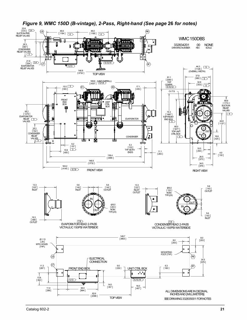
Figure 9, WMC 150D (B-vintage), 2-Pass, Right-hand (See page 26 for notes)
136.43466
146.93732
5.3
TYP.BOTHENDS
133
163.24145
11.1283
169.6 (UNITOVERALL)4307
17.1435
15.5393
15.9405
6.2157
29.2
CONDENSERRELIEFVALVES
742
58.2
EVAPORATORRELIEFVALVES
1479
FRONTVIEW
#1 #2
FRONTENDBOX
UNITCTRLBOX
CONDENSER
EVAPORATOR
XY
5,7,8
3
3
3
3
46.61184
46.01168
146.93732
22.6
SUCTION PIPERELIEFVALVES
574
21.8
EVAPORATORRELIEFVALVES
554
26.3
CONDENSERRELIEFVALVES
667
TOPVIEW
RB
RFLF
LB
ZX
4 4
3
3,4
3,4 5,13,145,13
5,7,8
16.8425
44.81137
74.3
TOPFRONTEND BOX
1887
81.1
TOPCOMPR.
2060
69.8
SUCTIONRELIEFVALVES
1774
44.3
(OVERALLWIDTH)1126
37.8960
32.8833
66.0
TOPUNITCTRLBOX
1677
10.0254
4.0102
26.5673
34.5876
RIGHTVIEW
IN
INOUT
OUT
O.I.T.S.
YZ
5
5
5
5
5
4
5,10,12
149.73802
34.5876
8.02038.0
2031.13
MTG.HOLES(TYP.)
29
11.4289
34.0864
82.62098
16.0407
14.0357
9.0230
6.3160
11.3287
13.8352
MOUNTINGFOOT(TYP.)
TOPVIEW
ELECTRICALCONNECTION
FRONTEND BOX UNITCTRL BOX
SEEDRAWING332835001 FORNOTES
LB
LF RF
RB
5,13 5,13,14
5.6
INLET142
5.6
OUTLET142
8.0
NOM.TYP.(2X)
203
EVAPORATORHEAD 2-PASSVICTAULIC150PSI WATERSIDE
IN
OUT
7,8
13.3
INLET337
19.3
OUTLET489
5.6
OUTLET143
5.6
INLET143
6.0
NOM.TYP.(2X)
152
CONDENSERHEAD 2-PASSVICTAULIC150PSI WATERSIDE
OUTIN
7,8
13.3
INLET/OUTLET
337
WMC150DBS
ALLDIMENSIONSAREIN DECIMALINCHESAND [MILLIMETERS]
332834201DRAWINGNUMBER
NONESCALE
00REV.
22 Catalog 602-2
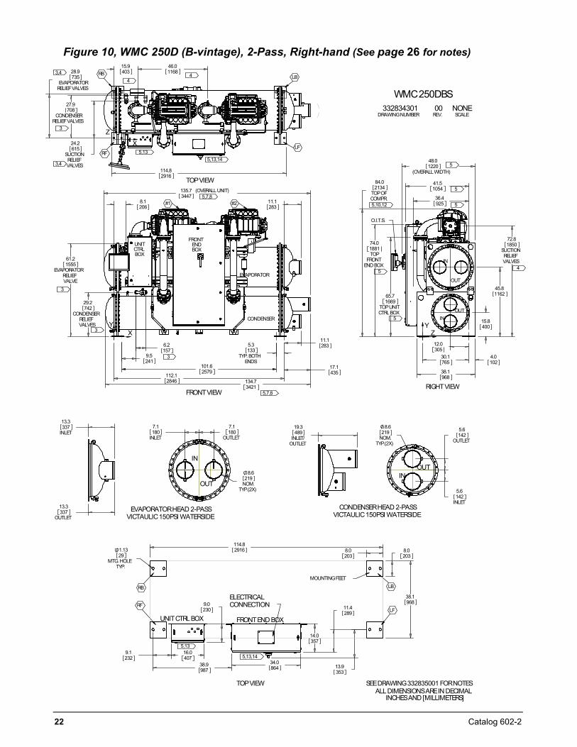
Figure 10, WMC 250D (B-vintage), 2-Pass, Right-hand (See page 26 for notes)
112.12846 134.7
3421
17.1435
11.1283
11.1283
29.2
CONDENSERRELIEFVALVES
742
61.2
EVAPORATORRELIEFVALVE
1555
135.7 (OVERALLUNIT)3447
6.2157
5.3
TYP.BOTHENDS
133
8.1206
101.62579
9.5241
FRONTVIEW
#1 #2
FRONTENDBOX
UNITCTRLBOX
CONDENSER
EVAPORATOR
XY
5,7,8
3
3
3
15.9403
46.01168
24.2
SUCTIONRELIEFVALVES
615
114.82916
28.9
EVAPORATORRELIEFVALVES
735
27.9
CONDENSERRELIEFVALVES
708
TOPVIEW
RB
RFLF
LB
Z
X
44
3
3,4
3,45,13,14
5,13
5,7,8
12.0305
30.1765
4.0102
38.1968
15.8400
45.81162
72.8
SUCTIONRELIEFVALVES
185074.0
TOPFRONT
END BOX
1881
84.0
TOPOFCOMPR.
213441.51054
48.0
(OVERALLWIDTH)1220
65.7
TOPUNITCTRLBOX
1669
36.4925
RIGHTVIEW
IN
INOUT
OUT
O.I.T.S.
YZ
5
5
5
5
5
4
5,10,12
8.0203
8.0203
38.1968
114.82916
9.1232
16.0407
9.0230
14.0357
11.4289
38.9987
34.0864
1.13
MTG.HOLETYP.
29
13.9353
MOUNTINGFEET
TOPVIEW
ELECTRICALCONNECTION
FRONTEND BOXUNITCTRLBOX
SEEDRAWING332835001 FORNOTES
LB
LFRF
RB
5,13
5,13,14
7.1
INLET180
7.1
OUTLET180
8.6
NOM.TYP.(2X)
219
EVAPORATORHEAD 2-PASSVICTAULIC150PSI WATERSIDE
IN
OUT
13.3
INLET337
13.3
OUTLET337
5.6
OUTLET142
5.6
INLET142
8.6
NOM.TYP.(2X)
219
CONDENSERHEAD 2-PASSVICTAULIC150PSI WATERSIDE
OUTIN
19.3
INLET/OUTLET
489
WMC250DBS
ALLDIMENSIONSAREIN DECIMALINCHESAND [MILLIMETERS]
332834301DRAWINGNUMBER
NONESCALE
00REV.
Catalog 602-2 23
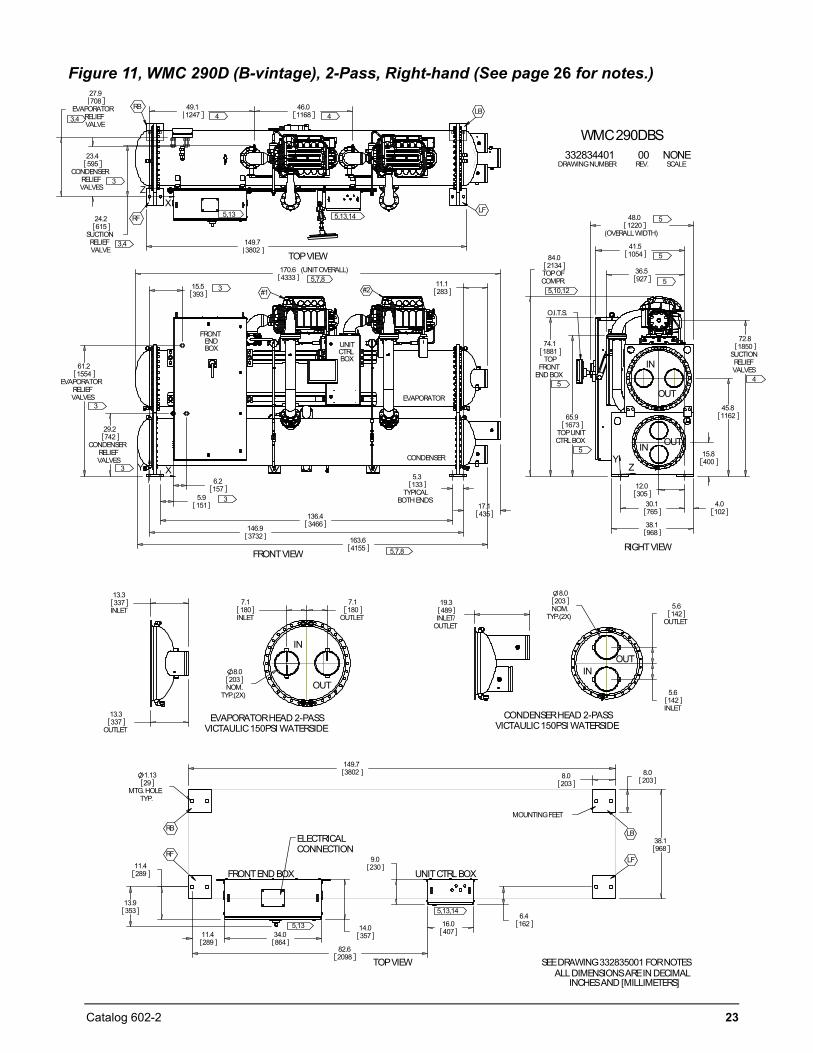
Figure 11, WMC 290D (B-vintage), 2-Pass, Right-hand (See page 26 for notes.)
146.93732
136.43466
61.2
EVAPORATORRELIEFVALVES
1554
170.6 (UNITOVERALL)4333
15.5393
5.9151
6.2157
17.1435
5.3
TYPICALBOTHENDS
133
11.1283
29.2
CONDENSERRELIEFVALVES
742
163.64155
FRONTVIEW
#1 #2
FRONTENDBOX UNIT
CTRLBOX
CONDENSER
EVAPORATOR
XY
5,7,8
3
3
3
3
24.2
SUCTIONRELIEFVALVE
615
27.9
EVAPORATORRELIEFVALVE
708
149.73802
23.4
CONDENSERRELIEFVALVES
595
49.11247
46.01168
TOPVIEW
RB
RFLF
LB
ZX
4 4
3
3,4
3,4
5,13,145,13
5,7,8
12.0305
30.1765
4.0102
38.1968
15.8400
45.81162
72.8
SUCTIONRELIEFVALVES
185074.1
TOPFRONT
END BOX
1881
84.0
TOPOFCOMPR.
2134
65.9
TOPUNITCTRLBOX
1673
36.5927
41.51054
48.0
(OVERALLWIDTH)1220
RIGHTVIEW
IN
IN OUT
OUT
O.I.T.S.
YZ
5
5
5
5
5
4
5,10,12
8.0203
8.0203
38.1968
149.738021.13
MTG.HOLETYP.
29
11.4289
34.0864
11.4289
82.62098
16.040714.0
357
9.0230
6.4162
13.9353
MOUNTINGFEET
TOPVIEW
ELECTRICALCONNECTION
FRONTEND BOX UNITCTRLBOX
SEEDRAWING332835001 FORNOTES
LB
LFRF
RB
5,13
5,13,14
7.1
INLET180
7.1
OUTLET180
8.0
NOM.TYP.(2X)
203
EVAPORATORHEAD 2-PASSVICTAULIC150PSI WATERSIDE
IN
OUT
13.3
INLET337
13.3
OUTLET337
5.6
OUTLET142
5.6
INLET142
8.0
NOM.TYP.(2X)
203
CONDENSERHEAD 2-PASSVICTAULIC150PSI WATERSIDE
OUTIN
19.3
INLET/OUTLET
489
WMC290DBS
ALLDIMENSIONSAREIN DECIMALINCHESAND [MILLIMETERS]
332834401DRAWINGNUMBER
NONESCALE
00REV.
24 Catalog 602-2
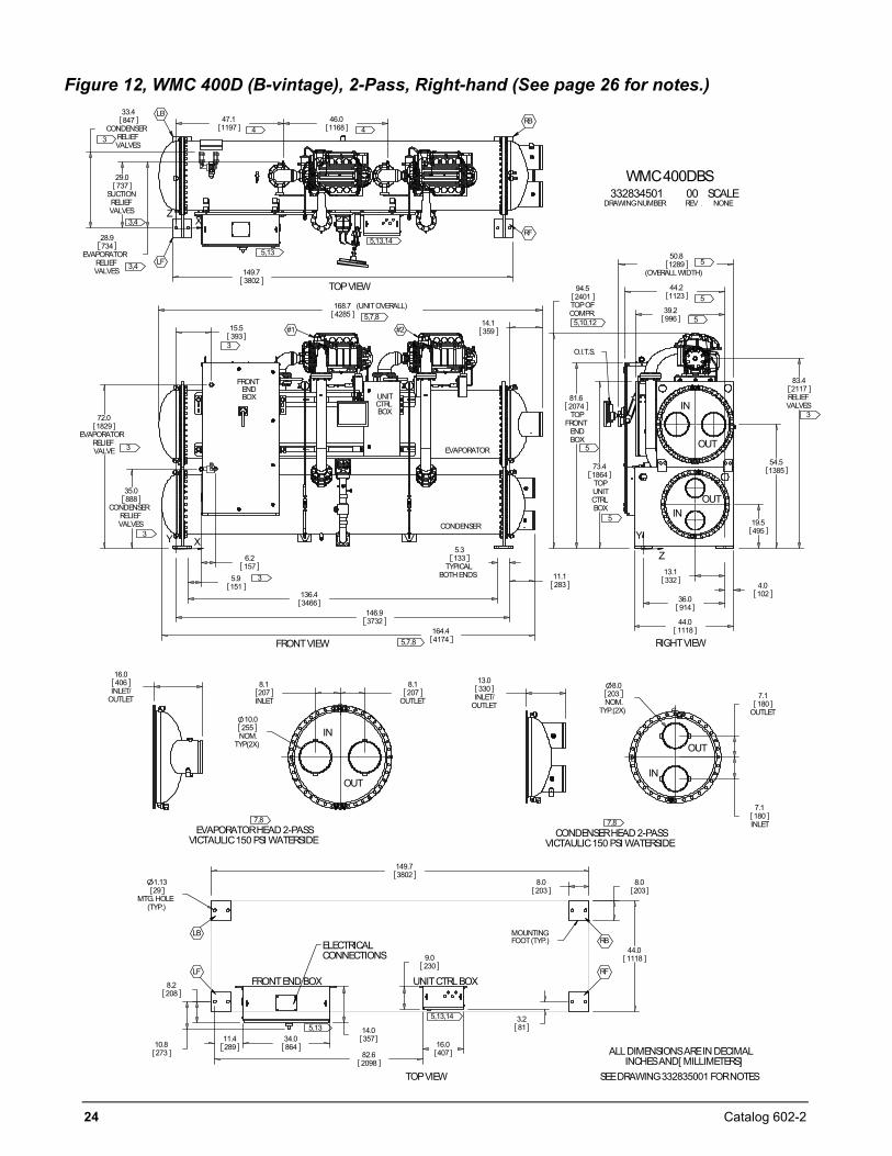
Figure 12, WMC 400D (B-vintage), 2-Pass, Right-hand (See page 26 for notes.)
136.43466
6.2157
5.9151
5.3
TYPICALBOTH ENDS
133
146.93732
164.44174
35.0
CONDENSERRELIEFVALVES
888
72.0
EVAPORATORRELIEFVALVE
1829
15.5393
11.1283
14.1359
168.7 (UNITOVERALL)4285
FRONTVIEW
CONDENSER
EVAPORATOR
FRONTENDBOX UNIT
CTRLBOX
#1 #2
XY
5,7,8
5,7,8
3
3
3
3
47.11197
46.01168
149.73802
28.9
EVAPORATORRELIEFVALVES
734
29.0
SUCTIONRELIEFVALVES
737
33.4
CONDENSERRELIEFVALVES
847
TOPVIEW
LB
LF
RB
ZX
4 43
3,4
3,4
5,135,13,14
RF
13.1332
36.0914
4.0102
44.01118
19.5495
54.51385
83.4
RELIEFVALVES
2117
73.4
TOPUNITCTRLBOX
1864
81.6
TOPFRONT
ENDBOX
2074
94.5
TOPOFCOMPR.
2401
50.8
(OVERALLWIDTH)1289
44.21123
39.2996
IN
IN
OUT
OUT
RIGHTVIEW
O.I.T.S.
Y
Z
5
5
5
5
5
3
5,10,12
149.73802
11.4289
34.0864
82.62098
16.0407
8.2208
14.0357
9.0230
3.281
8.0203
8.0203
1.13
MTG. HOLE(TYP.)
29
10.8273
44.01118
MOUNTINGFOOT(TYP.)ELECTRICAL
CONNECTIONS
TOPVIEW
FRONTEND BOX UNITCTRLBOX
WMC400DBS332834501 00 SCALE
DRAWINGNUMBER REV . NONE
ALLDIMENSIONSAREIN DECIMALINCHESAND[ MILLIMETERS]
SEEDRAWING332835001 FORNOTES
LF
LBRB
RF
5,135,13,14
7.1
OUTLET180
7.1
INLET180
8.0
NOM.TYP.(2X)
203
CONDENSERHEAD 2-PASSVICTAULIC150 PSI WATERSIDE
CL
CL
IN
OUT
7,8
13.0
INLET/OUTLET
3308.1
INLET207
8.1
OUTLET207
10.0
NOM.TYP(2X)
255
EVAPORATORHEAD 2-PASSVICTAULIC150 PSI WATERSIDE
CL
IN
OUT
7,8
16.0
INLET/OUTLET
406
CL
Catalog 602-2 25
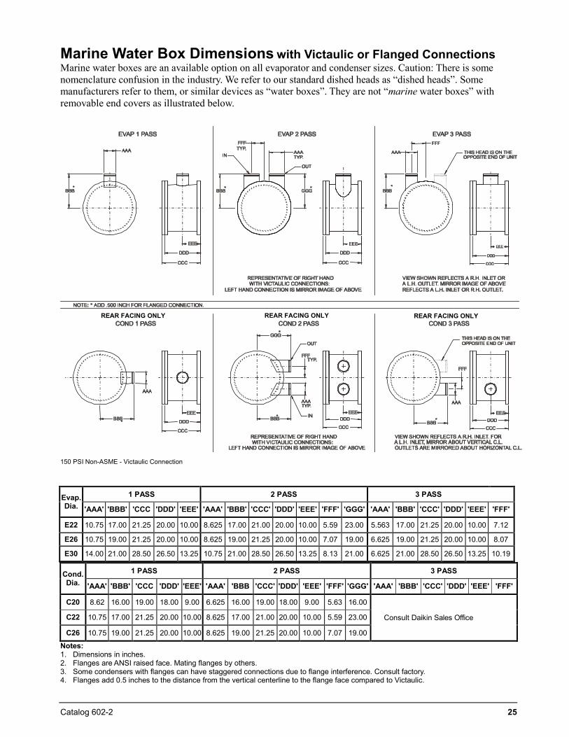
Marine Water Box Dimensions with Victaulic or Flanged Connections Marine water boxes are an available option on all evaporator and condenser sizes. Caution: There is some nomenclature confusion in the industry. We refer to our standard dished heads as “dished heads”. Some manufacturers refer to them, or similar devices as “water boxes”. They are not “marine water boxes” with removable end covers as illustrated below.
REAR FACING ONLY REAR FACING ONLY REAR FACING ONLY
150 PSI Non-ASME - Victaulic Connection
Cond. Dia.
1 PASS 2 PASS 3 PASS
'AAA' 'BBB' 'CCC 'DDD' 'EEE' 'AAA' 'BBB 'CCC' 'DDD' 'EEE' 'FFF' 'GGG' 'AAA' 'BBB' 'CCC' 'DDD' 'EEE' 'FFF'
C20 8.62 16.00 19.00 18.00 9.00 6.625 16.00 19.00 18.00 9.00 5.63 16.00
Consult Daikin Sales Office C22 10.75 17.00 21.25 20.00 10.00 8.625 17.00 21.00 20.00 10.00 5.59 23.00
C26 10.75 19.00 21.25 20.00 10.00 8.625 19.00 21.25 20.00 10.00 7.07 19.00
Notes: 1. Dimensions in inches.2. Flanges are ANSI raised face. Mating flanges by others.3. Some condensers with flanges can have staggered connections due to flange interference. Consult factory.4. Flanges add 0.5 inches to the distance from the vertical centerline to the flange face compared to Victaulic.
Evap. Dia.
1 PASS 2 PASS 3 PASS
'AAA' 'BBB' 'CCC 'DDD' 'EEE' 'AAA' 'BBB' 'CCC' 'DDD' 'EEE' 'FFF' 'GGG' 'AAA' 'BBB' 'CCC' 'DDD' 'EEE' 'FFF'
E22 10.75 17.00 21.25 20.00 10.00 8.625 17.00 21.00 20.00 10.00 5.59 23.00 5.563 17.00 21.25 20.00 10.00 7.12
E26 10.75 19.00 21.25 20.00 10.00 8.625 19.00 21.25 20.00 10.00 7.07 19.00 6.625 19.00 21.25 20.00 10.00 8.07
E30 14.00 21.00 28.50 26.50 13.25 10.75 21.00 28.50 26.50 13.25 8.13 21.00 6.625 21.00 28.50 26.50 13.25 10.19
26 Catalog 602-2
Drawing Notes NOTES:
1. All dimensions are in inches and [millimeters] unless noted otherwise. 2. Final connections must allow for .500 inch +/- [12.7mm] manufacturing tolerances. 3. 1.00-inch FPT [25.4 mm] evaporator and condenser relief valves must be piped per ANSI / ASHRAE
15. Number of relief valves is 1 per evaporator and 2 per condenser. 4. .375 inch [9 mm] suction nozzle relief valve must be piped per ANSI / ASHRAE 15. 5. Clearances:
Ends 108 inches (2743 mm) on WMC 145S/D and WMC 250D at one end 144 inches (3658 mm) on WMC 150D, WMC 290, and WMC 400D at one end
plus 36 inches (910 mm) is required at the opposite end. If tube pull and cleaning clearance is at the connection end, do not block tube access with piping, pumps, etc.
Sides 36 inches (914 mm) is recommended on all other sides and top for service clearance except unit front electric panels. See below..
Electric Panels Most codes require 48 inches (1219 mm) clearance in front of the control boxes and electrical panels.
6. 3.25-inch [83mm] diameter lifting holes are provided at the upper corners of each vessel. See installation manual for lifting instructions.
7. All water connections are given in standard U.S. pipe sizes. Standard Victaulic® connections are also suitable for welding.
8. The water connection shown is for the default configuration; your unit may be configured differently. Orientation (left/right) is determined while facing the control panel. Consult the Item Summary sheet for exact configuration. Unit shown has standard right-hand water connections. Left-hand connections are available for either vessel. For left hand evaporator the inlet and outlet nozzles are reversed. ANSI-flanged connections are available upon request. When using ANSI-flanged connections add .500 inch [13 mm] to each flanged end.
9. Dimensions shown are for units (evaporator / condenser) with standard design pressures. The refrigerant side design pressure is 200 PSI {1380 kPa} and the waterside design pressure is 150 PSI {1034 kPa}. Consult the factory for unit dimensions with higher design pressures.
10. The unit vibration isolator pads are provided for field installation. When fully loaded are 0.250 inches [6 mm] thick.
11. These values are for units with standard wall thickness copper tubing only. 12. The shipping skid adds 6.0 inches [152 mm] to the overall unit height. 13. All-power wiring is brought into the top of the compressor power panel (Front End Box). Field control
wiring is brought into the Unit Control Box. 14. The unit is shipped with an operating charge of refrigerant. 15. Optional marine water box connections are available upon request.
Catalog 602-2 27
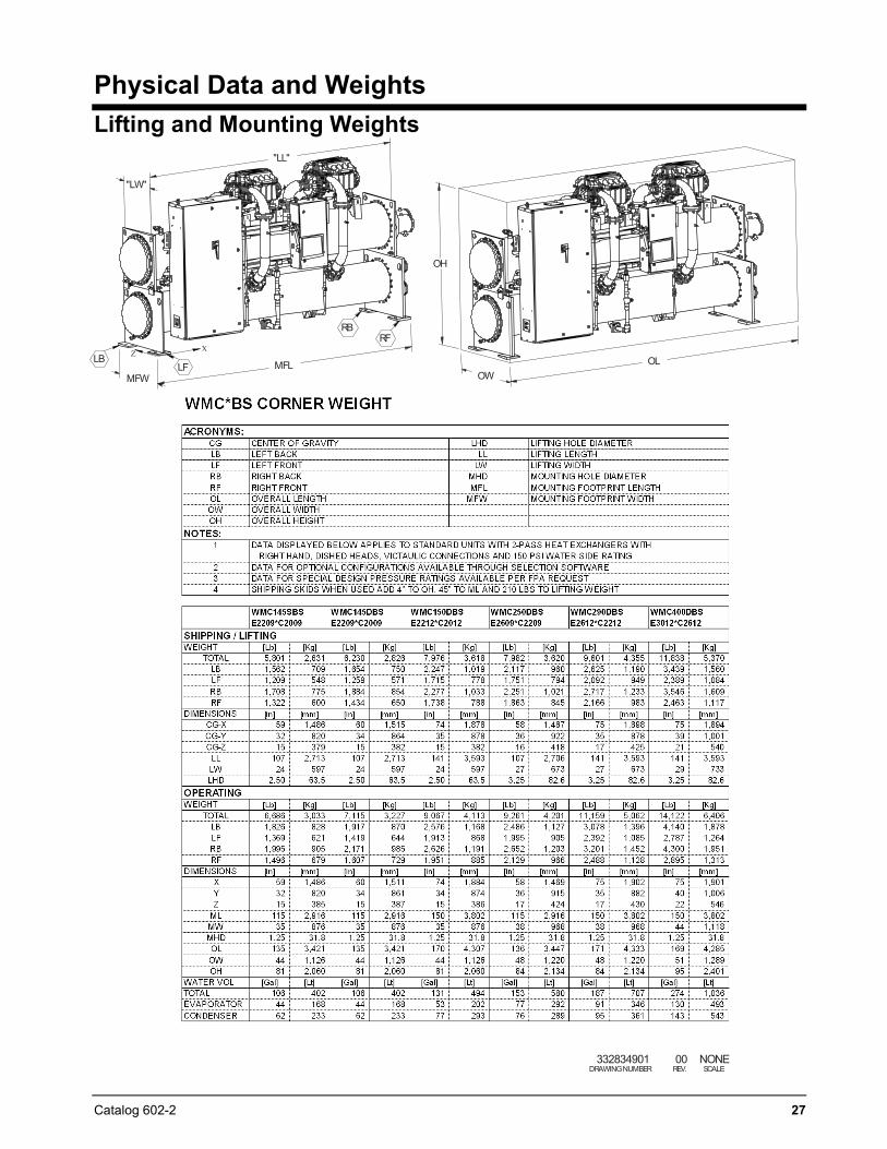
Physical Data and Weights Lifting and Mounting Weights
"LL"
"LW"
MFLMFW
XZ
RFRB
LBLF
OH
OWOL
332834901DRAWINGNUMBER
00REV.
NONESCALE
28 Catalog 602-2
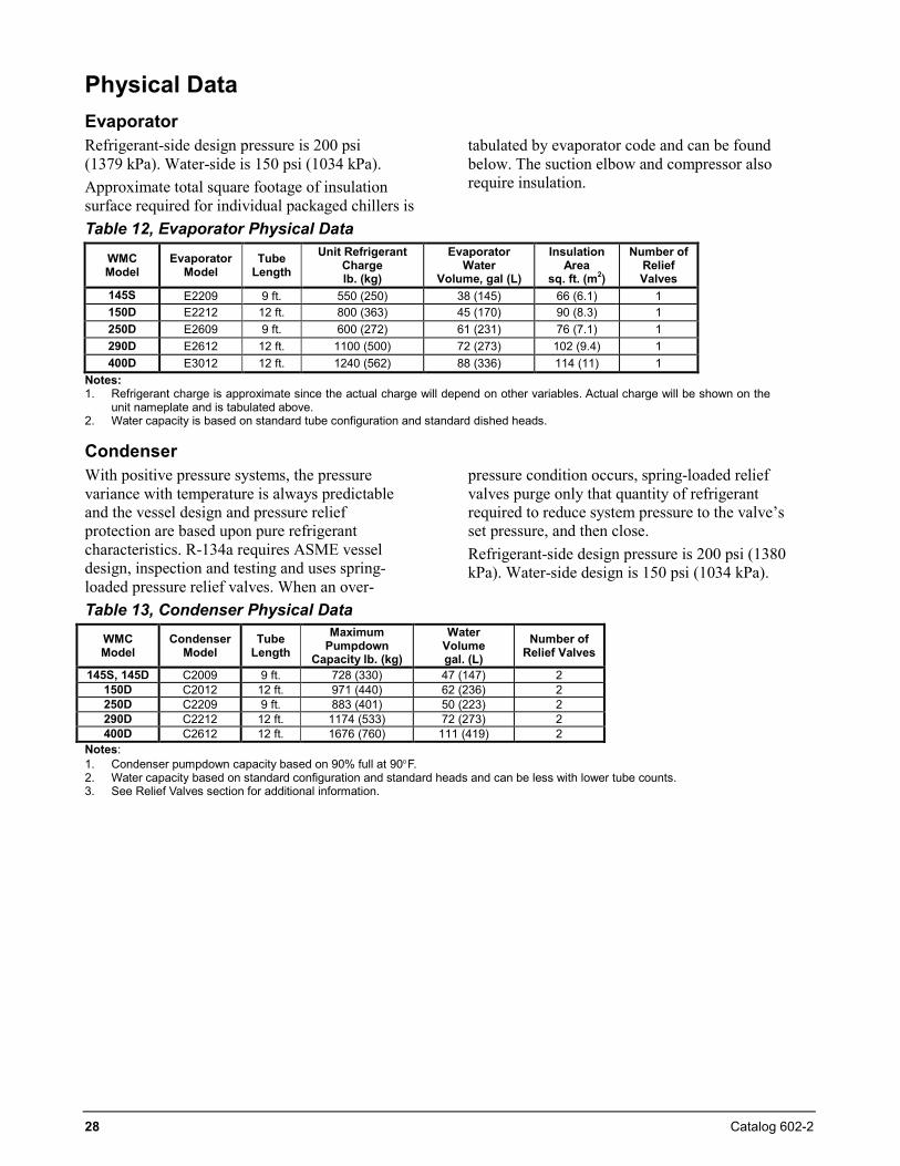
Physical Data Evaporator Refrigerant-side design pressure is 200 psi (1379 kPa). Water-side is 150 psi (1034 kPa). Approximate total square footage of insulation surface required for individual packaged chillers is
tabulated by evaporator code and can be found below. The suction elbow and compressor also require insulation.
Table 12, Evaporator Physical Data
WMC Model
Evaporator Model
Tube Length
Unit Refrigerant Charge lb. (kg)
Evaporator Water
Volume, gal (L)
Insulation Area
sq. ft. (m2)
Number of Relief Valves
145S
E2209 9 ft. 550 (250) 38 (145) 66 (6.1) 1 150D E2212 12 ft. 800 (363) 45 (170) 90 (8.3) 1 250D E2609 9 ft. 600 (272) 61 (231) 76 (7.1) 1 290D E2612 12 ft. 1100 (500) 72 (273) 102 (9.4) 1 400D E3012 12 ft. 1240 (562) 88 (336) 114 (11) 1
Notes: 1. Refrigerant charge is approximate since the actual charge will depend on other variables. Actual charge will be shown on the
unit nameplate and is tabulated above. 2. Water capacity is based on standard tube configuration and standard dished heads.
Condenser With positive pressure systems, the pressure variance with temperature is always predictable and the vessel design and pressure relief protection are based upon pure refrigerant characteristics. R-134a requires ASME vessel design, inspection and testing and uses spring-loaded pressure relief valves. When an over-
pressure condition occurs, spring-loaded relief valves purge only that quantity of refrigerant required to reduce system pressure to the valve’s set pressure, and then close. Refrigerant-side design pressure is 200 psi (1380 kPa). Water-side design is 150 psi (1034 kPa).
Table 13, Condenser Physical Data WMC Model
Condenser Model
Tube Length
Maximum Pumpdown
Capacity lb. (kg)
Water Volume gal. (L)
Number of Relief Valves
145S, 145D C2009 9 ft. 728 (330) 47 (147) 2 150D C2012 12 ft. 971 (440) 62 (236) 2 250D C2209 9 ft. 883 (401) 50 (223) 2 290D C2212 12 ft. 1174 (533) 72 (273) 2 400D C2612 12 ft. 1676 (760) 111 (419) 2
Notes: 1. Condenser pumpdown capacity based on 90% full at 90°F. 2. Water capacity based on standard configuration and standard heads and can be less with lower tube counts. 3. See Relief Valves section for additional information.
Catalog 602-2 29
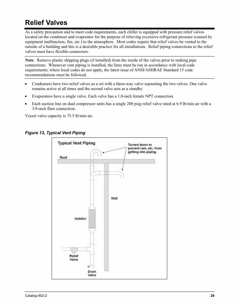
Relief Valves As a safety precaution and to meet code requirements, each chiller is equipped with pressure relief valves located on the condenser and evaporator for the purpose of relieving excessive refrigerant pressure (caused by equipment malfunction, fire, etc.) to the atmosphere. Most codes require that relief valves be vented to the outside of a building and this is a desirable practice for all installations. Relief piping connections to the relief valves must have flexible connectors.
Note: Remove plastic shipping plugs (if installed) from the inside of the valves prior to making pipe connections. Whenever vent piping is installed, the lines must be run in accordance with local code requirements; where local codes do not apply, the latest issue of ANSI/ASHRAE Standard 15 code recommendations must be followed.
• Condensers have two relief valves as a set with a three-way valve separating the two valves. One valve remains active at all times and the second valve acts as a standby.
• Evaporators have a single valve. Each valve has a 1.0-inch female NPT connection.
• Each suction line on dual compressor units has a single 200 psig relief valve rated at 6.9 lb/min air with a 3/8-inch flare connection.
Vessel valve capacity is 75.5 lb/min air.
Figure 13, Typical Vent Piping
30 Catalog 602-2
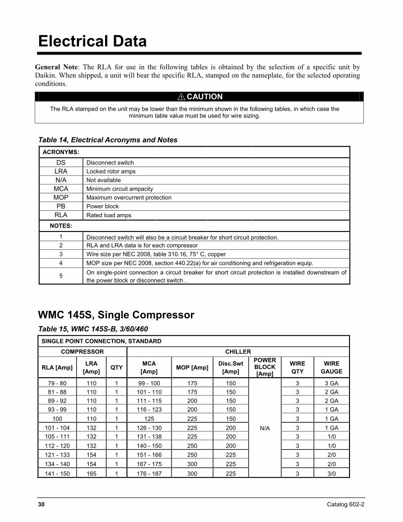
Electrical Data General Note: The RLA for use in the following tables is obtained by the selection of a specific unit by Daikin. When shipped, a unit will bear the specific RLA, stamped on the nameplate, for the selected operating conditions.
CAUTIONThe RLA stamped on the unit may be lower than the minimum shown in the following tables, in which case the
minimum table value must be used for wire sizing.
Table 14, Electrical Acronyms and Notes ACRONYMS:
DS Disconnect switch LRA Locked rotor amps N/A Not available MCA Minimum circuit ampacity MOP Maximum overcurrent protection PB Power block
RLA Rated load amps
NOTES:
1 Disconnect switch will also be a circuit breaker for short circuit protection. 2 RLA and LRA data is for each compressor 3 Wire size per NEC 2008, table 310.16, 75° C, copper 4 MOP size per NEC 2008, section 440.22(a) for air conditioning and refrigeration equip.
5 On single-point connection a circuit breaker for short circuit protection is installed downstream of the power block or disconnect switch .
WMC 145S, Single Compressor Table 15, WMC 145S-B, 3/60/460
SINGLE POINT CONNECTION, STANDARD
COMPRESSOR CHILLER
RLA [Amp] LRA [Amp] QTY MCA
[Amp] MOP [Amp] Disc.Swt [Amp]
POWER BLOCK [Amp]
WIRE QTY
WIRE GAUGE
79 - 80 110 1 99 - 100 175 150
N/A
3 3 GA 81 - 88 110 1 101 - 110 175 150 3 2 GA 89 - 92 110 1 111 - 115 200 150 3 2 GA 93 - 99 110 1 116 - 123 200 150 3 1 GA
100 110 1 125 225 150 3 1 GA 101 - 104 132 1 126 - 130 225 200 3 1 GA 105 - 111 132 1 131 - 138 225 200 3 1/0 112 - 120 132 1 140 - 150 250 200 3 1/0 121 - 133 154 1 151 - 166 250 225 3 2/0 134 - 140 154 1 167 - 175 300 225 3 2/0 141 - 150 165 1 176 - 187 300 225 3 3/0
!
Catalog 602-2 31
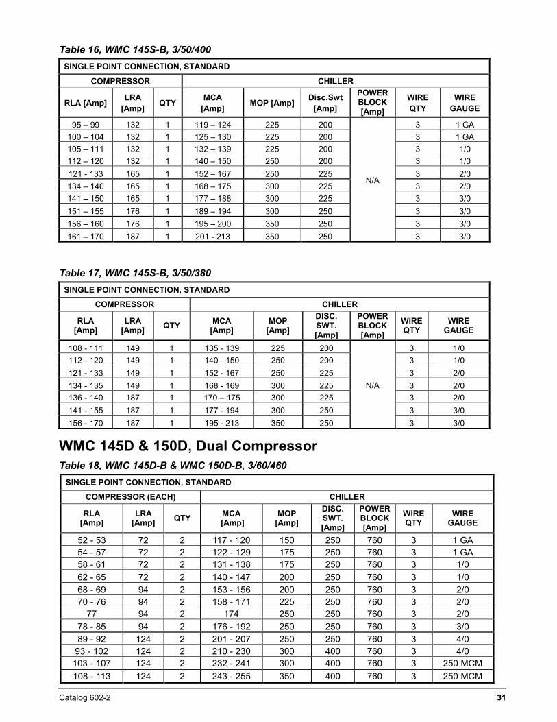
Table 16, WMC 145S-B, 3/50/400 SINGLE POINT CONNECTION, STANDARD
COMPRESSOR CHILLER
RLA [Amp] LRA [Amp] QTY MCA
[Amp] MOP [Amp] Disc.Swt [Amp]
POWER BLOCK [Amp]
WIRE QTY
WIRE GAUGE
95 – 99 132 1 119 – 124 225 200
N/A
3 1 GA 100 – 104 132 1 125 – 130 225 200 3 1 GA 105 – 111 132 1 132 – 139 225 200 3 1/0 112 – 120 132 1 140 – 150 250 200 3 1/0 121 - 133 165 1 152 – 167 250 225 3 2/0 134 – 140 165 1 168 – 175 300 225 3 2/0 141 – 150 165 1 177 – 188 300 225 3 3/0 151 – 155 176 1 189 – 194 300 250 3 3/0 156 – 160 176 1 195 – 200 350 250 3 3/0 161 – 170 187 1 201 - 213 350 250 3 3/0
Table 17, WMC 145S-B, 3/50/380 SINGLE POINT CONNECTION, STANDARD
COMPRESSOR CHILLER
RLA [Amp]
LRA [Amp] QTY MCA
[Amp] MOP
[Amp] DISC. SWT. [Amp]
POWER BLOCK [Amp]
WIRE QTY
WIRE GAUGE
108 - 111 149 1 135 - 139 225 200
N/A
3 1/0 112 - 120 149 1 140 - 150 250 200 3 1/0 121 - 133 149 1 152 - 167 250 225 3 2/0 134 - 135 149 1 168 - 169 300 225 3 2/0 136 - 140 187 1 170 – 175 300 225 3 2/0 141 - 155 187 1 177 - 194 300 250 3 3/0 156 - 170 187 1 195 - 213 350 250 3 3/0
WMC 145D & 150D, Dual Compressor Table 18, WMC 145D-B & WMC 150D-B, 3/60/460
SINGLE POINT CONNECTION, STANDARD
COMPRESSOR (EACH) CHILLER
RLA [Amp]
LRA [Amp] QTY MCA
[Amp] MOP
[Amp] DISC. SWT. [Amp]
POWERBLOCK [Amp]
WIRE QTY
WIRE GAUGE
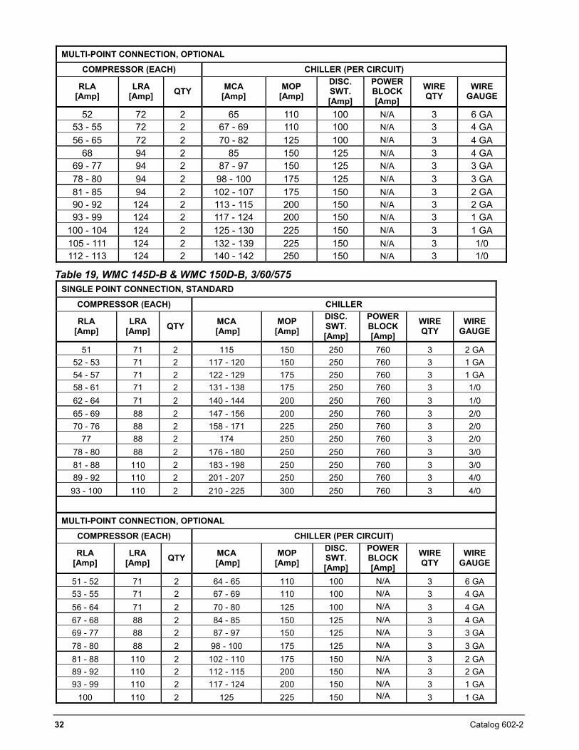
52 - 53 72 2 117 - 120 150 250 760 3 1 GA 54 - 57 72 2 122 - 129 175 250 760 3 1 GA 58 - 61 72 2 131 - 138 175 250 760 3 1/0 62 - 65 72 2 140 - 147 200 250 760 3 1/0 68 - 69 94 2 153 - 156 200 250 760 3 2/0 70 - 76 94 2 158 - 171 225 250 760 3 2/0
77 94 2 174 250 250 760 3 2/0 78 - 85 94 2 176 - 192 250 250 760 3 3/0 89 - 92 124 2 201 - 207 250 250 760 3 4/0
93 - 102 124 2 210 - 230 300 400 760 3 4/0 103 - 107 124 2 232 - 241 300 400 760 3 250 MCM 108 - 113 124 2 243 - 255 350 400 760 3 250 MCM
32 Catalog 602-2
MULTI-POINT CONNECTION, OPTIONAL
COMPRESSOR (EACH) CHILLER (PER CIRCUIT)
RLA [Amp]
LRA [Amp] QTY MCA
[Amp] MOP
[Amp] DISC. SWT. [Amp]
POWERBLOCK [Amp]
WIRE QTY
WIRE GAUGE
52 72 2 65 110 100 N/A 3 6 GA 53 - 55 72 2 67 - 69 110 100 N/A 3 4 GA 56 - 65 72 2 70 - 82 125 100 N/A 3 4 GA
68 94 2 85 150 125 N/A 3 4 GA 69 - 77 94 2 87 - 97 150 125 N/A 3 3 GA 78 - 80 94 2 98 - 100 175 125 N/A 3 3 GA 81 - 85 94 2 102 - 107 175 150 N/A 3 2 GA 90 - 92 124 2 113 - 115 200 150 N/A 3 2 GA 93 - 99 124 2 117 - 124 200 150 N/A 3 1 GA
100 - 104 124 2 125 - 130 225 150 N/A 3 1 GA 105 - 111 124 2 132 - 139 225 150 N/A 3 1/0 112 - 113 124 2 140 - 142 250 150 N/A 3 1/0
Table 19, WMC 145D-B & WMC 150D-B, 3/60/575 SINGLE POINT CONNECTION, STANDARD
COMPRESSOR (EACH) CHILLER
RLA [Amp]
LRA [Amp] QTY MCA
[Amp] MOP
[Amp]
DISC. SWT. [Amp]
POWERBLOCK [Amp]
WIRE QTY
WIRE GAUGE
51 71 2 115 150 250 760 3 2 GA 52 - 53 71 2 117 - 120 150 250 760 3 1 GA 54 - 57 71 2 122 - 129 175 250 760 3 1 GA 58 - 61 71 2 131 - 138 175 250 760 3 1/0 62 - 64 71 2 140 - 144 200 250 760 3 1/0 65 - 69 88 2 147 - 156 200 250 760 3 2/0 70 - 76 88 2 158 - 171 225 250 760 3 2/0
77 88 2 174 250 250 760 3 2/0 78 - 80 88 2 176 - 180 250 250 760 3 3/0 81 - 88 110 2 183 - 198 250 250 760 3 3/0 89 - 92 110 2 201 - 207 250 250 760 3 4/0 93 - 100 110 2 210 - 225 300 250 760 3 4/0
MULTI-POINT CONNECTION, OPTIONAL
COMPRESSOR (EACH) CHILLER (PER CIRCUIT)
RLA [Amp]
LRA [Amp] QTY MCA
[Amp] MOP
[Amp]
DISC. SWT. [Amp]
POWERBLOCK [Amp]
WIRE QTY
WIRE GAUGE
51 - 52 71 2 64 - 65 110 100 N/A 3 6 GA 53 - 55 71 2 67 - 69 110 100 N/A 3 4 GA 56 - 64 71 2 70 - 80 125 100 N/A 3 4 GA 67 - 68 88 2 84 - 85 150 125 N/A 3 4 GA 69 - 77 88 2 87 - 97 150 125 N/A 3 3 GA 78 - 80 88 2 98 - 100 175 125 N/A 3 3 GA 81 - 88 110 2 102 - 110 175 150 N/A 3 2 GA 89 - 92 110 2 112 - 115 200 150 N/A 3 2 GA 93 - 99 110 2 117 - 124 200 150 N/A 3 1 GA
100 110 2 125 225 150 N/A 3 1 GA
Catalog 602-2 33
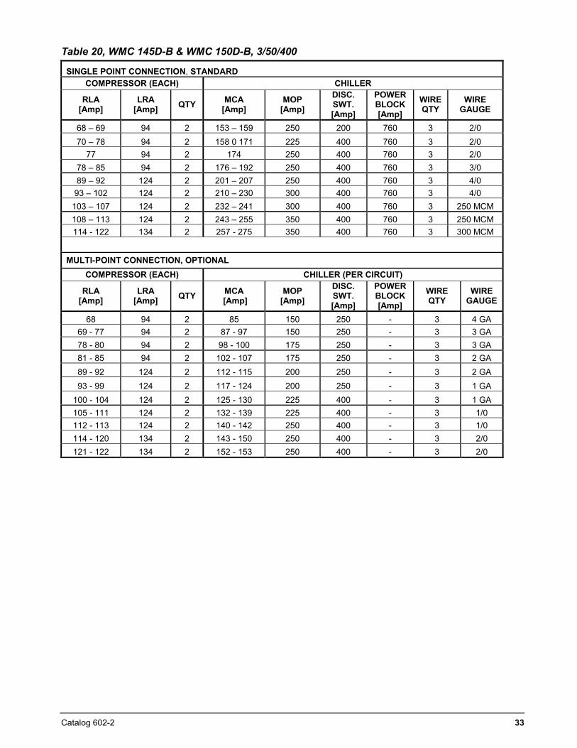
Table 20, WMC 145D-B & WMC 150D-B, 3/50/400
SINGLE POINT CONNECTION, STANDARD COMPRESSOR (EACH) CHILLER
RLA [Amp]
LRA [Amp] QTY MCA
[Amp] MOP
[Amp] DISC. SWT. [Amp]
POWER BLOCK [Amp]
WIRE QTY
WIRE GAUGE
68 – 69 94 2 153 – 159 250 200 760 3 2/0 70 – 78 94 2 158 0 171 225 400 760 3 2/0
77 94 2 174 250 400 760 3 2/0 78 – 85 94 2 176 – 192 250 400 760 3 3/0 89 – 92 124 2 201 – 207 250 400 760 3 4/0
93 – 102 124 2 210 – 230 300 400 760 3 4/0 103 – 107 124 2 232 – 241 300 400 760 3 250 MCM 108 – 113 124 2 243 – 255 350 400 760 3 250 MCM 114 - 122 134 2 257 - 275 350 400 760 3 300 MCM
MULTI-POINT CONNECTION, OPTIONAL
COMPRESSOR (EACH) CHILLER (PER CIRCUIT)
RLA [Amp]
LRA [Amp] QTY MCA
[Amp] MOP
[Amp] DISC. SWT. [Amp]
POWER BLOCK [Amp]
WIRE QTY
WIRE GAUGE
68 94 2 85 150 250 - 3 4 GA 69 - 77 94 2 87 - 97 150 250 - 3 3 GA 78 - 80 94 2 98 - 100 175 250 - 3 3 GA 81 - 85 94 2 102 - 107 175 250 - 3 2 GA 89 - 92 124 2 112 - 115 200 250 - 3 2 GA 93 - 99 124 2 117 - 124 200 250 - 3 1 GA
100 - 104 124 2 125 - 130 225 400 - 3 1 GA 105 - 111 124 2 132 - 139 225 400 - 3 1/0 112 - 113 124 2 140 - 142 250 400 - 3 1/0 114 - 120 134 2 143 - 150 250 400 - 3 2/0 121 - 122 134 2 152 - 153 250 400 - 3 2/0
34 Catalog 602-2
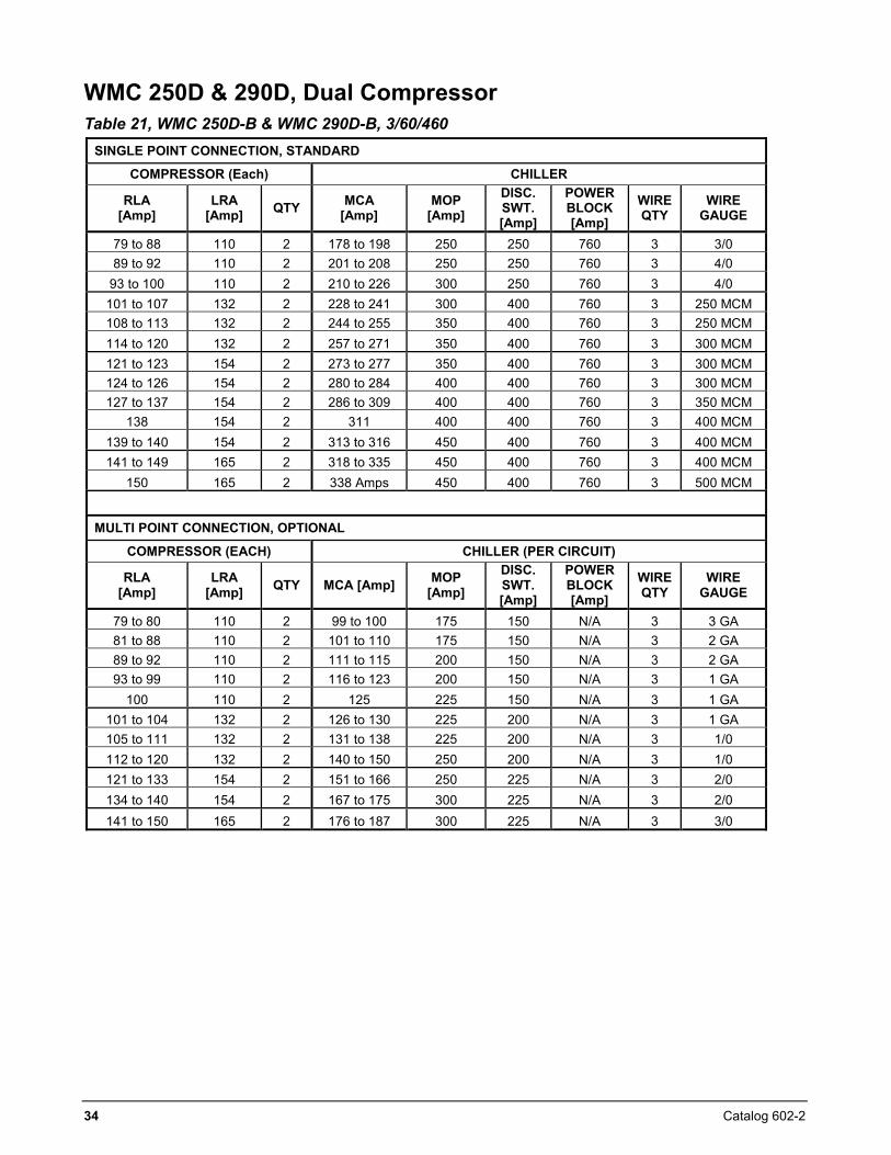
WMC 250D & 290D, Dual Compressor Table 21, WMC 250D-B & WMC 290D-B, 3/60/460
SINGLE POINT CONNECTION, STANDARD
COMPRESSOR (Each) CHILLER
RLA [Amp]
LRA [Amp] QTY MCA
[Amp] MOP
[Amp] DISC. SWT. [Amp]
POWER BLOCK [Amp]
WIRE QTY
WIRE GAUGE
79 to 88 110 2 178 to 198 250 250 760 3 3/0 89 to 92 110 2 201 to 208 250 250 760 3 4/0
93 to 100 110 2 210 to 226 300 250 760 3 4/0 101 to 107 132 2 228 to 241 300 400 760 3 250 MCM 108 to 113 132 2 244 to 255 350 400 760 3 250 MCM 114 to 120 132 2 257 to 271 350 400 760 3 300 MCM 121 to 123 154 2 273 to 277 350 400 760 3 300 MCM 124 to 126 154 2 280 to 284 400 400 760 3 300 MCM 127 to 137 154 2 286 to 309 400 400 760 3 350 MCM
138 154 2 311 400 400 760 3 400 MCM 139 to 140 154 2 313 to 316 450 400 760 3 400 MCM 141 to 149 165 2 318 to 335 450 400 760 3 400 MCM
150 165 2 338 Amps 450 400 760 3 500 MCM
MULTI POINT CONNECTION, OPTIONAL
COMPRESSOR (EACH) CHILLER (PER CIRCUIT)
RLA [Amp]
LRA [Amp] QTY MCA [Amp] MOP
[Amp]
DISC. SWT. [Amp]
POWER BLOCK [Amp]
WIRE QTY
WIRE GAUGE
79 to 80 110 2 99 to 100 175 150 N/A 3 3 GA 81 to 88 110 2 101 to 110 175 150 N/A 3 2 GA 89 to 92 110 2 111 to 115 200 150 N/A 3 2 GA 93 to 99 110 2 116 to 123 200 150 N/A 3 1 GA
100 110 2 125 225 150 N/A 3 1 GA 101 to 104 132 2 126 to 130 225 200 N/A 3 1 GA 105 to 111 132 2 131 to 138 225 200 N/A 3 1/0 112 to 120 132 2 140 to 150 250 200 N/A 3 1/0 121 to 133 154 2 151 to 166 250 225 N/A 3 2/0 134 to 140 154 2 167 to 175 300 225 N/A 3 2/0 141 to 150 165 2 176 to 187 300 225 N/A 3 3/0
Catalog 602-2 35
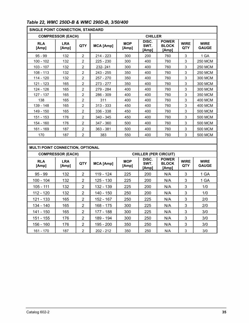
Table 22, WMC 250D-B & WMC 290D-B, 3/50/400 SINGLE POINT CONNECTION, STANDARD
COMPRESSOR (EACH) CHILLER
RLA [Amp]
LRA [Amp] QTY MCA [Amp] MOP
[Amp]
DISC. SWT. [Amp]
POWER BLOCK [Amp]
WIRE QTY
WIRE GAUGE
95 - 99 132 2 214 - 223 300 200 760 3 1 GA 100 - 102 132 2 225 - 230 300 400 760 3 250 MCM 103 - 107 132 2 232- 241 300 400 760 3 250 MCM 108 - 113 132 2 243 - 255 350 400 760 3 250 MCM 114 - 120 132 2 257 - 270 350 400 760 3 300 MCM 121 - 123 165 2 273 - 277 350 400 760 3 300 MCM 124 - 126 165 2 279 - 284 400 400 760 3 300 MCM 127 - 137 165 2 286 - 309 400 400 760 3 350 MCM
138 165 2 311 400 400 760 3 400 MCM 139 - 148 165 2 313 - 333 450 400 760 3 400 MCM 149 - 150 165 2 336 - 338 450 400 760 3 500 MCM 151 - 153 176 2 340 - 345 450 400 760 3 500 MCM 154 - 160 176 2 347 - 360 500 400 760 3 500 MCM 161 - 169 187 2 363 - 381 500 400 760 3 500 MCM
170 187 2 383 550 400 760 3 500 MCM
MULTI POINT CONNECTION, OPTIONAL
COMPRESSOR (EACH) CHILLER (PER CIRCUIT)
RLA [Amp]
LRA [Amp] QTY MCA [Amp] MOP
[Amp] DISC. SWT. [Amp]
POWER BLOCK [Amp]
WIRE QTY
WIRE GAUGE
95 - 99 132 2 119 - 124 225 200 N/A 3 1 GA 100 - 104 132 2 125 - 130 225 200 N/A 3 1 GA 105 - 111 132 2 132 - 139 225 200 N/A 3 1/0 112 - 120 132 2 140 - 150 250 200 N/A 3 1/0 121 - 133 165 2 152 - 167 250 225 N/A 3 2/0 134 - 140 165 2 168 - 175 300 225 N/A 3 2/0 141 - 150 165 2 177 - 188 300 225 N/A 3 3/0 151 - 155 176 2 189 - 194 300 250 N/A 3 3/0 156 - 160 176 2 195 - 200 350 250 N/A 3 3/0 161 - 170 187 2 202 - 212 350 250 N/A 3 3/0
36 Catalog 602-2
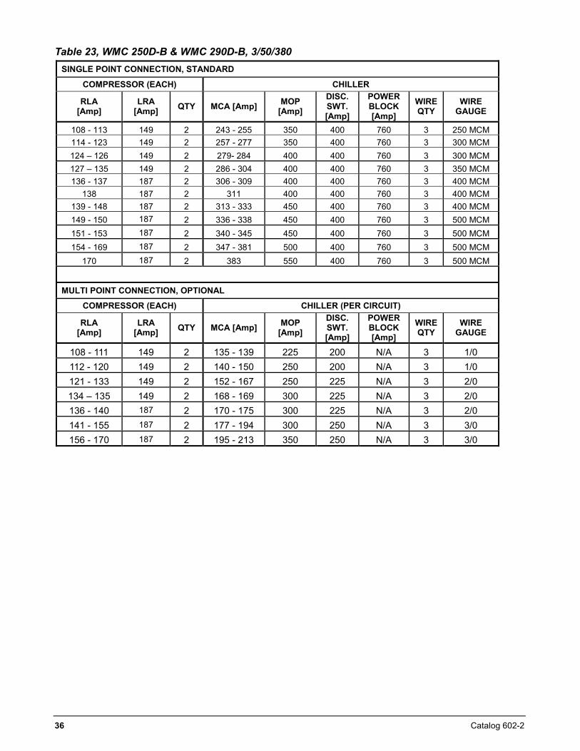
Table 23, WMC 250D-B & WMC 290D-B, 3/50/380 SINGLE POINT CONNECTION, STANDARD
COMPRESSOR (EACH) CHILLER
RLA [Amp]
LRA [Amp] QTY MCA [Amp] MOP
[Amp]
DISC. SWT. [Amp]
POWER BLOCK [Amp]
WIRE QTY
WIRE GAUGE
108 - 113 149 2 243 - 255 350 400 760 3 250 MCM 114 - 123 149 2 257 - 277 350 400 760 3 300 MCM 124 – 126 149 2 279- 284 400 400 760 3 300 MCM 127 – 135 149 2 286 - 304 400 400 760 3 350 MCM 136 - 137 187 2 306 - 309 400 400 760 3 400 MCM
138 187 2 311 400 400 760 3 400 MCM 139 - 148 187 2 313 - 333 450 400 760 3 400 MCM 149 - 150 187 2 336 - 338 450 400 760 3 500 MCM 151 - 153 187 2 340 - 345 450 400 760 3 500 MCM 154 - 169 187 2 347 - 381 500 400 760 3 500 MCM
170 187 2 383 550 400 760 3 500 MCM
MULTI POINT CONNECTION, OPTIONAL
COMPRESSOR (EACH) CHILLER (PER CIRCUIT)
RLA [Amp]
LRA [Amp] QTY MCA [Amp] MOP
[Amp] DISC. SWT. [Amp]
POWER BLOCK [Amp]
WIRE QTY
WIRE GAUGE
108 - 111 149 2 135 - 139 225 200 N/A 3 1/0 112 - 120 149 2 140 - 150 250 200 N/A 3 1/0 121 - 133 149 2 152 - 167 250 225 N/A 3 2/0 134 – 135 149 2 168 - 169 300 225 N/A 3 2/0 136 - 140 187 2 170 - 175 300 225 N/A 3 2/0 141 - 155 187 2 177 - 194 300 250 N/A 3 3/0 156 - 170 187 2 195 - 213 350 250 N/A 3 3/0
Catalog 602-2 37
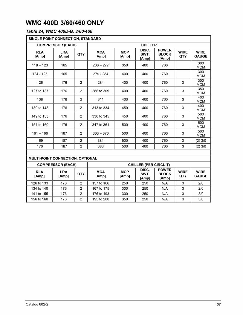
WMC 400D 3/60/460 ONLY Table 24, WMC 400D-B, 3/60/460
SINGLE POINT CONNECTION, STANDARD
COMPRESSOR (EACH) CHILLER
RLA [Amp]
LRA [Amp] QTY MCA
[Amp] MOP
[Amp] DISC. SWT. [Amp]
POWER BLOCK [Amp]
WIRE QTY
WIRE GAUGE
118 – 123 165 266 – 277 350 400 760 300 MCM
124 - 125 165 279 - 284 400 400 760 300 MCM
126 176 2 284 400 400 760 3 300 MCM
127 to 137 176 2 286 to 309 400 400 760 3 350 MCM
138 176 2 311 400 400 760 3 400 MCM
139 to 148 176 2 313 to 334 450 400 760 3 400 MCM
149 to 153 176 2 336 to 345 450 400 760 3 500 MCM
154 to 160 176 2 347 to 361 500 400 760 3 500 MCM
161 – 166 187 2 363 – 376 500 400 760 3 500 MCM
169 187 2 381 500 400 760 3 (2) 3/0 170 187 2 383 500 400 760 3 (2) 3/0
MULTI-POINT CONNECTION, OPTIONAL
COMPRESSOR (EACH) CHILLER (PER CIRCUIT)
RLA [Amp]
LRA [Amp] QTY MCA
[Amp] MOP
[Amp] DISC. SWT. [Amp]
POWER BLOCK [Amp]
WIRE QTY
WIRE GAUGE
126 to 133 176 2 157 to 166 250 250 N/A 3 2/0 134 to 140 176 2 167 to 175 300 250 N/A 3 2/0 141 to 155 176 2 176 to 193 300 250 N/A 3 3/0 156 to 160 176 2 195 to 200 350 250 N/A 3 3/0
38 Catalog 602-2
Notes for following field wiring diagram 1. COMPRESSOR FRONT END BOX IS FACTORY
MOUNTED AND WIRED. ALL LINE SIDE WIRING MUST BE WIRED IN ACCORDANCE WITH THE NEC AND BE MADE WITH COPPER WIRE AND COPPER LUGS ONLY. USE ONLY COPPER SUPPLY WIRES WITH AMPACITY BASED ON 75°C CONDUCTOR RATING. MAIN POWER WIRING BETWEEN THE FRONT END BOX AND COMPRESSOR TERMINALS IS FACTORY INSTALLED.
2. MINIMUM WIRE SIZE FOR 115 VAC IS 12 GA. FOR A MAXIMUM LENGTH OF 50 FEET. IF GREATER THAN 50 FEET REFER TO Daikin FOR RECOMMENDED WIRE SIZE MINIMUM. WIRE SIZE FOR 24 VAC IS 18 GA. ALL WIRING TO BE INSTALLED AS NEC CLASS 1 WIRING SYSTEM. ALL 24 VAC WIRING MUST BE RUN IN SEPARATE CONDUIT FROM 115 VAC WIRING. WIRING MUST BE WIRED IN ACCORDANCE WITH NEC AND CONNECTION TO BE MADE WITH COPPER WIRE ANC COPPER LUGS ONLY.
3. FOR OPTIONAL SENSOR WIRING SEE UNITCONTROL DIAGRAM. IT IS RECOMMENDED THAT DC WIRES BE RUN SEPARATELY FROM 115 VAC WIRING.
4. A CUSTOMER FURNISHED 24 OR 120 VAC POWERFOR ALARM RELAY COIL MAY BE CONNECTEDBETWEEN UTB1 TERMINALS 84 POWER AND 81NEUTRAL OF THE CONTROL PANEL. FORNORMALLY OPEN CONTACTS WIRE BETWEEN 82 &81. FOR NORMALLY CLOSED WIRE BETWEEN 83 &81. THE ALARM IS OPERATOR PROGRAMMABLE.MAXIMUM RATING OF THE ALARM RELAY COIL IS 25VA.
5. REMOTE ON/OFF CONTROL OF UNIT CAN BEACCOMPLISHED BY INSTALLING A SET OF DRY CONTACTS BETWEEN TERMINALS 70 AND 54.
6. THERMAL DISPERSION FLOW SWITCHES FOR THEEVAPORATOR AND CONDENSER ARE FACTORYMOUNTED AS STANDARD AND PROVIDE ADEQUETFLOW LOSS PROTECTION. IF DESIRED,ADDITIONAL FLOW OR PRESSURE DIFFERENTIALSWITCHES CAN BE CUSTOMER SUPPLIED,MOUNTED AND WIRED AS SHOWN. A FACTORYWIRED EVAP FLOW SWITCH IS CONNECTEDBETWEEN EF1 & EF2, AND A COND FLOW SWITCHBETWEEN CF1 & CF2. ANY ADDITIONAL DEVICESMUST BE WIRED IN SERIES WITH THEM.IF FIELD SUPPLIED PRESSURE DIFFERENTIALSWITCHES ARE USED THEN THESE MUST BEINSTALLED ACROSS THE VESSEL AND NOT THE
PUMP. THEY MUST BE SUITABLE FOR 24 VAC AND LOW CURRENT APPLICATION.
7. CUSTOMER SUPPLIED 115 VAC 20 AMP POWER FOROPTIONAL EVAP AND COND WATER PUMPCONTROL POWER AND TOWER FANS IS SUPPLIEDTO UNIT CONTROL TERMINALS (UTB1) 85 POWER /86 NEUTRAL, PE EQUIPMENT GROUND.
8. OPTIONAL CUSTOMER SUPPLIED 115 VAC 25 VAMAXIMUM COIL RATED CHILLED WATER PUMPRELAY (EP1 AND EP2) MAY BE WIRED AS SHOWN.THIS OPTIONAL WILL CYCLE THE CHILLEDWATER PUMP IN RESPONSE TO CHILLER DEMAND.
9. THE CONDENSER WATER PUMP MUST CYCLEWITH THE UNIT. A CUSTOMER SUPPLIED 115 VAC 25 VA MAXIMUM COIL RATED CONDENSER WATER PUMP RELAY (CP1 & 2) IS TO BE WIRED AS SHOWN. UNITS WITH FREE COOLING MUST HAVE CONDENSER WATER ABOVE 60° BEFORE STARTING.
10. OPTIONAL CUSTOMER SUPPLIED 115 VAC 25 VAMAXIMUM COIL RATED COOLING TOWER FAN RELAYS (C1 – C2 STANDARD, C3 – C4 OPTIONAL) MAY BE WIRED AS SHOWN. THIS OPTION WILL CYCLE THE COOLING TOWER FANS IN ORDER TO MAINTAIN UNIT HEAD PRESSURE.
11. AUXILIARY 24 VAC RATED CONTACTS IN BOTHTHE CHILLED WATER AND CONDENSER WATERPUMP STARTERS SHOULD BE WIRED AS SHOWN.
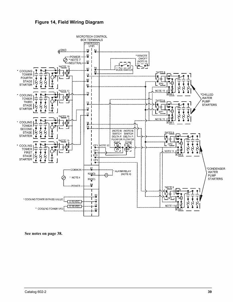
Catalog 602-2 39
Figure 14, Field Wiring Diagram
See notes on page 38.
40 Catalog 602-2
Power Factor Correction Do not use power factor correction capacitors with WMC chillers. Doing so can cause harmful electrical resonance in the system. Correction capacitors are not necessary since VFDs inherently maintain high power factors. The full load power factor exceeds 0.90 for all units.
VFD Line Harmonics Despite their many benefits, care must be taken when applying VFDs due to the effect of line harmonics on the building electric system. VFDs cause distortion of the AC line because they are nonlinear loads, that is, they don't draw sinusoidal current from the line. They draw their current from only the peaks of the AC line, thereby flattening the top of the voltage waveform. Some other nonlinear loads are electronic ballasts and uninterruptible power supplies.
Line harmonics and their associated distortion can be critical to ac-drives for three reasons:
1. Current harmonics can cause additional heating to transformers, conductors, and switchgear.
2. Voltage harmonics upset the smooth voltage sinusoidal waveform.
3. High-frequency components of voltage distortion can interfere with signals transmitted on the AC line for some control systems.
The harmonics of concern are the 5th, 7th, 11th, and 13th. Even harmonics, harmonics divisible by three, and high magnitude harmonics are usually not a problem. Current Harmonics An increase in reactive impedance in front of the VFD helps reduce the harmonic currents. Reactive impedance can be added in the following ways:
1. Mount the drive far from the source transformer.
2. Add line reactors. They are standard equipment on Magnitude chillers.
3. Use an isolation transformer. 4. Use a harmonic filter.
Voltage Harmonics Voltage distortion is caused by the flow of harmonic currents through a source impedance. A reduction in source impedance to the point of common coupling (PCC) will result in a reduction
in voltage harmonics. This can be done in the following ways:
1. Keep the PCC as far from the drives (close to the power source) as possible.
2. Increase the size (decrease the impedance) of the source transformer.
3. Increase the capacity (decrease the impedance) of the busway or cables from the source to the PCC.
4. Make sure that added reactance is "downstream" (closer to the VFD than the source) from the PCC.
Line Reactors Five-percent line reactors are standard equipment on Magnitude chillers and located in each compressors power panel. They are employed to improve the power factor by reducing the effects of harmonics. Optional Harmonic Filter The Institute of Electrical and Electronics Engineers (IEEE) has developed a standard (IEEE519) that defines acceptable limits of site specific system current and voltage distortion. The designer may wish to consult this standard to ensure acceptable levels of harmonic distortion are maintained. Harmonic filters are available as a field mounted and wired accessory, wired from the chiller power panel circuit breakers out to the filter and back to the chiller’s power fuses and contactors. They limit current distortion and improve unit power factor. The filters are mounted in a UL Type 1 enclosure and are UL and cUL listed. The smallest filter Model HG60 is wall mounted, the balance are floor mounted. The harmonic filter package includes power blocks, a 5% impedance line reactor, tuning reactor, a contactor and a capacitor bank. When the harmonic filter is selected, the normal line reactor in the unit’s main electrical panel is removed at the factory. A power monitoring package is included as standard. It consists of indication lights for filter operation and fuse failure on the HG60 size. Filters from size HG75 and up consist of a display board showing operating information such as current and voltage total harmonic distortion, true power factor and a series of fault and protection codes. It can be programmed to shut off under fault conditions or when the drive goes into a fault condition.
Catalog 602-2 41
The filter size selection is based on the WMC Rated Load Amps (RLA) as determined by a computerized chiller selection program. The local Daikin sales office can provide selection and pricing information. Filter dimensions, weights and terminal size range can be found in the WMC Installation manual IM 1029-2. EMI (Electro Magnetic Interference) and RFI (Radio Frequency Interference) Filter This filter is a factory-installed option. The terms EMI and RFI are often used interchangeably. EMI is actually any frequency of electrical noise, whereas RFI is a specific subset of electrical noise on the EMI spectrum. There are two types of EMI.
Conducted EMI is unwanted high frequencies that ride on the AC wave form. EMI-Radiated EMI is similar to an unwanted radio broadcast being emitted from the power lines. There are many pieces of equipment that can generate EMI, variable frequency drives included. In the case of variable frequency drives, the electrical noise produced is primarily contained in the switching edges of the pulse width modulation (PWM) controller. As the technology of drives evolves, switching frequencies increase. These increases also increase the effective edge frequencies produced, thereby increasing the amount of electrical noise.
The power line noise emissions associated with variable frequency and variable speed drives can cause disturbances in nearby equipment. Typical disturbances include: • Dimmer and ballast instability• Lighting disturbances such as flashing• Poor radio reception• Poor television reception• Instability of control systems• Flow meter totalizing• Flow metering fluctuation
VFD Harmonic Considerations The Institute of Electrical and Electronics Engineers (IEEE) has developed a standard (IEEE519) that defines acceptable limits of site specific system current and voltage distortion. The designer may wish to consult this standard to ensure acceptable levels of harmonic distortion are maintained.
• Radar disruption• Sonar disruption• Computer system failures loss of data
Catalog 602-2 42
Application Considerations
Location WMC chillers are intended only for installation in an indoor or weather protected area consistent with the NEMA 1 rating on the chiller, controls, and electrical panels. Equipment room temperature for operating and standby conditions is 40°F to 104°F (4.4°C to 40°C). Optimum Water Temperatures and Flow A key to improving energy efficiency for any chiller is minimizing the compressor pressure lift. Reducing the lift reduces the compressor work and its energy consumption per unit of output. The chiller typically has the largest motor of any component in a chilled water system. Higher leaving chilled water temperatures Warmer leaving chilled water temperatures will raise the compressor’s suction pressure and decrease the lift, improving efficiency. Using 45°F (7.0°C) leaving water instead of 42°F (5.5°C) will make a significant improvement. Evaporator temperature drop The industry standard has been a 10-degree F (5.5 degree C) temperature drop in the evaporator. Increasing the drop to 12 or 14 degrees F (6.6 or 7.7 degrees C) will improve the evaporator heat transfer, raise the suction pressure, and improve chiller efficiency. Chilled water pump energy will also be reduced.
Condenser entering water temperature As a general rule, a one-degree drop in condenser entering water temperature will reduce chiller energy consumption by two percent. Cooler water lowers the condensing pressure and reduces compressor work. One or two degrees can make a noticeable difference. The incremental cost of a larger tower can be small and provide a good return on investment. Condenser water temperature rise The industry standard of 3 gpm/ton or about a 9.5-degree delta-T seems to work well for most applications. Reducing condenser water flow to lower pumping energy will increase the water temperature rise, resulting in an increase in the compressor’s condensing pressure and energy consumption. This is usually not a productive strategy. Chilled Water Temperature The maximum temperature of water entering the chiller on standby must not exceed 110° F (43° C). Maximum temperature entering on start-up must not exceed 90°F (32.2°C). Minimum chilled water leaving temperature without antifreeze is approximately 36°F (2.2°C).
Piping Piping must be adequately supported to remove weight and strain on the chiller’s fittings and connections. Be sure piping is adequately insulated. Install a cleanable 20-mesh water strainer at the inlet of the evaporator and condenser. Install enough shutoff valves to permit draining water from the evaporator or condenser without draining the complete system.
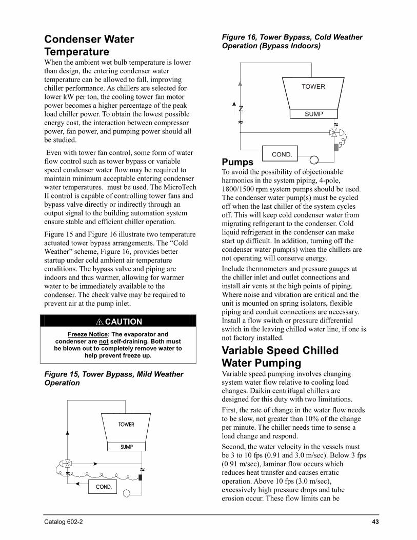
Catalog 602-2 43
Condenser Water Temperature When the ambient wet bulb temperature is lower than design, the entering condenser water temperature can be allowed to fall, improving chiller performance. As chillers are selected for lower kW per ton, the cooling tower fan motor power becomes a higher percentage of the peak load chiller power. To obtain the lowest possible energy cost, the interaction between compressor power, fan power, and pumping power should all be studied.
Even with tower fan control, some form of water flow control such as tower bypass or variable speed condenser water flow may be required to maintain minimum acceptable entering condenser water temperatures. must be used. The MicroTech II control is capable of controlling tower fans and bypass valve directly or indirectly through an output signal to the building automation system ensure stable and efficient chiller operation.
Figure 15 and Figure 16 illustrate two temperature actuated tower bypass arrangements. The “Cold Weather” scheme, Figure 16, provides better startup under cold ambient air temperature conditions. The bypass valve and piping are indoors and thus warmer, allowing for warmer water to be immediately available to the condenser. The check valve may be required to prevent air at the pump inlet.
Figure 15, Tower Bypass, Mild Weather Operation
Figure 16, Tower Bypass, Cold Weather Operation (Bypass Indoors)
Pumps To avoid the possibility of objectionable harmonics in the system piping, 4-pole, 1800/1500 rpm system pumps should be used. The condenser water pump(s) must be cycled off when the last chiller of the system cycles off. This will keep cold condenser water from migrating refrigerant to the condenser. Cold liquid refrigerant in the condenser can make start up difficult. In addition, turning off the condenser water pump(s) when the chillers are not operating will conserve energy. Include thermometers and pressure gauges at the chiller inlet and outlet connections and install air vents at the high points of piping. Where noise and vibration are critical and the unit is mounted on spring isolators, flexible piping and conduit connections are necessary. Install a flow switch or pressure differential switch in the leaving chilled water line, if one is not factory installed.
Variable Speed Chilled Water Pumping Variable speed pumping involves changing system water flow relative to cooling load changes. Daikin centrifugal chillers are designed for this duty with two limitations. First, the rate of change in the water flow needs to be slow, not greater than 10% of the change per minute. The chiller needs time to sense a load change and respond. Second, the water velocity in the vessels must be 3 to 10 fps (0.91 and 3.0 m/sec). Below 3 fps (0.91 m/sec), laminar flow occurs which reduces heat transfer and causes erratic operation. Above 10 fps (3.0 m/sec), excessively high pressure drops and tube erosion occur. These flow limits can be
CAUTIONFreeze Notice: The evaporator and
condenser are not self-draining. Both must be blown out to completely remove water to
help prevent freeze up.
!
≈ ≈
≈ ≈
44 Catalog 602-2
determined from the Daikin selection program. We recommend variable flow only in the evaporator because there is virtually no change in chiller efficiency compared to constant flow. In other words, there is no chiller energy penalty and considerable pumping energy can be saved. Although variable speed pumping can be done in the condenser loop, it is usually unwise. The intent of variable flow is to reduce pump horsepower. However, reducing condenser water flow increases the chiller’s condensing pressure, increasing the lift that the compressor must overcome which, in turn, increases the compressor’s energy use. Consequently, pump energy savings can be lost because the chiller operating power is significantly increased. Low condenser flow and tube velocities can cause premature tube fouling and subsequent increased compressor power consumption. Increased cleaning and/or chemical use can also result.
Vibration Mounting The Magnitude chillers are almost vibration-free. Consequently, floor mounted spring isolators are not usually required. Rubber mounting pads are shipped with each unit. It is wise to continue to use piping flexible connectors to reduce sound transmitted into the pipe and to allow for expansion and contraction.
System Water Volume All chilled water systems need adequate time to recognize a load change, respond to that load change and stabilize, without undesirable short cycling of the compressors or loss of control. In air conditioning systems, the potential for short cycling usually exists when the building load falls below the minimum chiller plant capacity or on close-coupled systems with very small water volumes. Some of the things the designer should consider when looking at water volume are the minimum cooling load, the minimum chiller plant capacity
during the low load period and the desired cycle time for the compressors. Assuming that there are no sudden load changes and the chiller plant has reasonable turndown, a rule of thumb of “gallons of water volume equal to two to three times the chilled water gpm flow rate” is often used. A properly designed storage tank should be added if the system components do not provide sufficient water volume.
Pump Control Operation of the chilled water pump can be to: 1) cycle the pump with the unit2) operate continuously3) cycle automatically by a remote sourceThe cooling tower pump must cycle with the compressor. The holding coil of the cooling tower pump motor starter must be rated at 115 volts, 60 Hz, with a maximum volt-amperage rating of 100. A control relay is required if the voltage-amperage rating is exceeded. See the Field Wiring Diagram on page 39 or in the cover of control panel for proper connections. All interlock contacts must be rated for no less than 10 inductive amps. The alarm circuit provided in the control center utilizes 115-volts AC. The alarm used must not draw more than 10-volt amperes.
System analysis Although Daikin is a proponent of analyzing the entire system, it is generally effective to place the chiller in the most efficient mode because it is a large energy consumer.
The Daikin Energy Analyzer program is an excellent tool to investigate the entire system efficiency, quickly and accurately. It is especially good at comparing different system types and operating parameters. Contact you local Daikin sales office for assistance on your particular application.
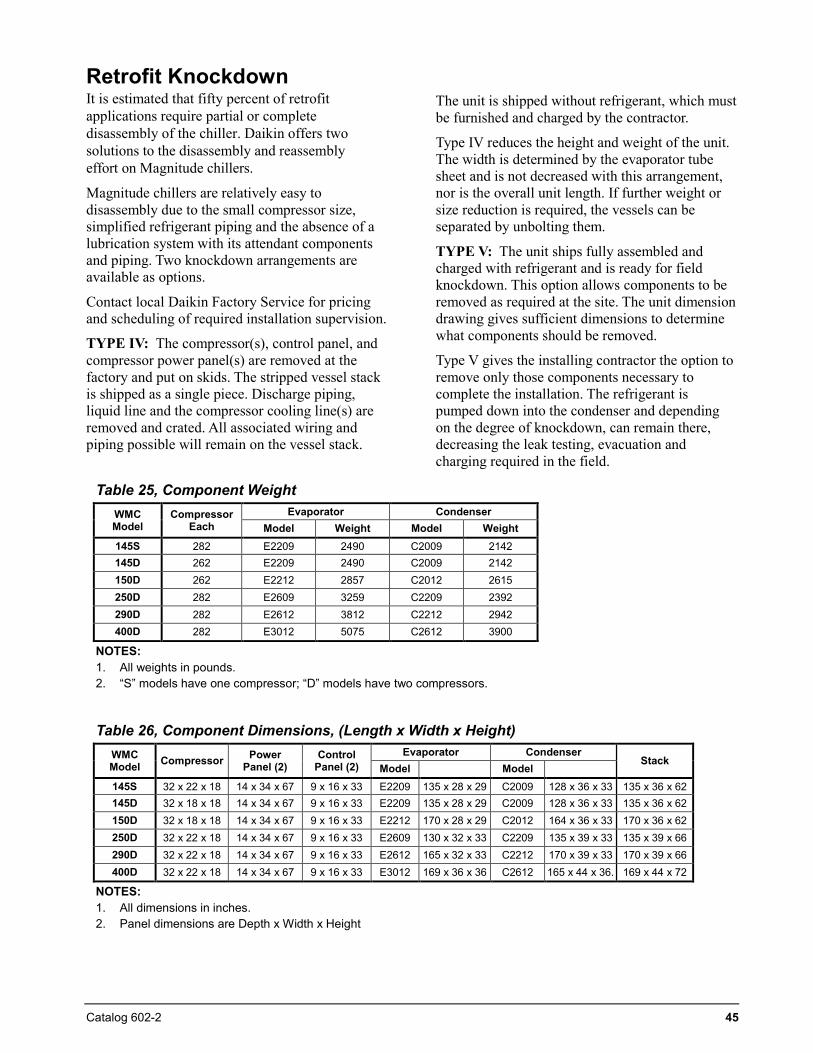
Catalog 602-2 45
Retrofit Knockdown It is estimated that fifty percent of retrofit applications require partial or complete disassembly of the chiller. Daikin offers two solutions to the disassembly and reassembly effort on Magnitude chillers.
Magnitude chillers are relatively easy to disassembly due to the small compressor size, simplified refrigerant piping and the absence of a lubrication system with its attendant components and piping. Two knockdown arrangements are available as options.
Contact local Daikin Factory Service for pricing and scheduling of required installation supervision.
TYPE IV: The compressor(s), control panel, and compressor power panel(s) are removed at the factory and put on skids. The stripped vessel stack is shipped as a single piece. Discharge piping, liquid line and the compressor cooling line(s) are removed and crated. All associated wiring and piping possible will remain on the vessel stack.
The unit is shipped without refrigerant, which must be furnished and charged by the contractor.
Type IV reduces the height and weight of the unit. The width is determined by the evaporator tube sheet and is not decreased with this arrangement, nor is the overall unit length. If further weight or size reduction is required, the vessels can be separated by unbolting them.
TYPE V: The unit ships fully assembled and charged with refrigerant and is ready for field knockdown. This option allows components to be removed as required at the site. The unit dimension drawing gives sufficient dimensions to determine what components should be removed.
Type V gives the installing contractor the option to remove only those components necessary to complete the installation. The refrigerant is pumped down into the condenser and depending on the degree of knockdown, can remain there, decreasing the leak testing, evacuation and charging required in the field.
Table 25, Component Weight WMC Model
Compressor Each
Evaporator Condenser Model Weight Model Weight
145S 282 E2209 2490 C2009 2142 145D 262 E2209 2490 C2009 2142 150D 262 E2212 2857 C2012 2615 250D 282 E2609 3259 C2209 2392 290D 282 E2612 3812 C2212 2942 400D 282 E3012 5075 C2612 3900
NOTES: 1. All weights in pounds.2. “S” models have one compressor; “D” models have two compressors.
Table 26, Component Dimensions, (Length x Width x Height) WMC Model Compressor Power
Panel (2) Control
Panel (2) Evaporator Condenser
Stack Model Model
145S 32 x 22 x 18 14 x 34 x 67 9 x 16 x 33 E2209 135 x 28 x 29 C2009 128 x 36 x 33 135 x 36 x 62 145D 32 x 18 x 18 14 x 34 x 67 9 x 16 x 33 E2209 135 x 28 x 29 C2009 128 x 36 x 33 135 x 36 x 62 150D 32 x 18 x 18 14 x 34 x 67 9 x 16 x 33 E2212 170 x 28 x 29 C2012 164 x 36 x 33 170 x 36 x 62 250D 32 x 22 x 18 14 x 34 x 67 9 x 16 x 33 E2609 130 x 32 x 33 C2209 135 x 39 x 33 135 x 39 x 66 290D 32 x 22 x 18 14 x 34 x 67 9 x 16 x 33 E2612 165 x 32 x 33 C2212 170 x 39 x 33 170 x 39 x 66 400D 32 x 22 x 18 14 x 34 x 67 9 x 16 x 33 E3012 169 x 36 x 36 C2612 165 x 44 x 36. 169 x 44 x 72
NOTES: 1. All dimensions in inches.2. Panel dimensions are Depth x Width x Height
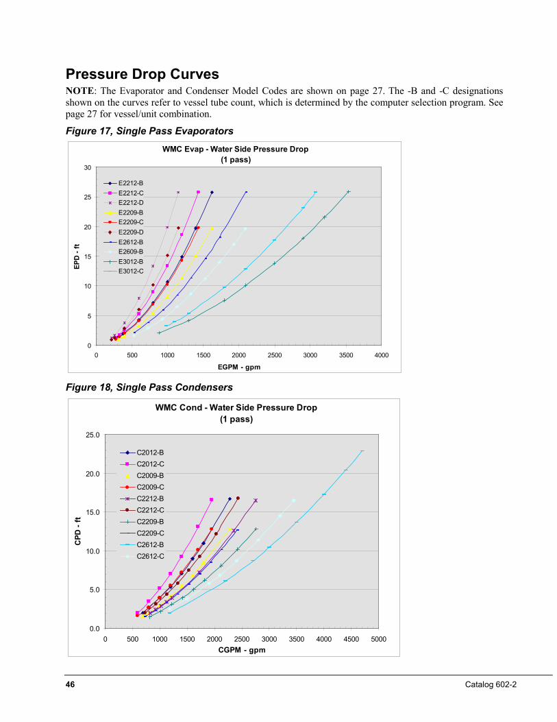
46 Catalog 602-2
Pressure Drop Curves NOTE: The Evaporator and Condenser Model Codes are shown on page 27. The -B and -C designations shown on the curves refer to vessel tube count, which is determined by the computer selection program. See page 27 for vessel/unit combination.
Figure 17, Single Pass Evaporators
Figure 18, Single Pass Condensers
WMC Evap - Water Side Pressure Drop(1 pass)
0
5
10
15
20
25
30
0 500 1000 1500 2000 2500 3000 3500 4000
EGPM - gpm
EPD
- ft
E2212-BE2212-CE2212-DE2209-BE2209-CE2209-DE2612-BE2609-BE3012-BE3012-C
WMC Cond - Water Side Pressure Drop(1 pass)
0.0
5.0
10.0
15.0
20.0
25.0
0 500 1000 1500 2000 2500 3000 3500 4000 4500 5000CGPM - gpm
CPD
- ft
C2012-BC2012-CC2009-BC2009-CC2212-BC2212-CC2209-BC2209-CC2612-BC2612-C
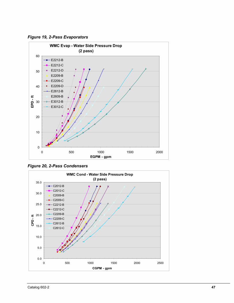
Catalog 602-2 47
Figure 19, 2-Pass Evaporators
Figure 20, 2-Pass Condensers
WMC Evap - Water Side Pressure Drop(2 pass)
0
10
20
30
40
50
60
0 500 1000 1500 2000EGPM - gpm
EPD
- ft
E2212-BE2212-CE2212-DE2209-BE2209-CE2209-DE2612-BE2609-BE3012-BE3012-C
WMC Cond - Water Side Pressure Drop(2 pass)
0.0
5.0
10.0
15.0
20.0
25.0
30.0
35.0
0 500 1000 1500 2000 2500
CGPM - gpm
CPD
- ft
C2012-BC2012-CC2009-BC2009-CC2212-BC2212-CC2209-BC2209-CC2612-BC2612-C
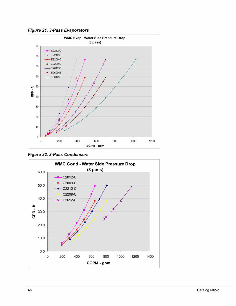
48 Catalog 602-2
Figure 21, 3-Pass Evaporators
Figure 22, 3-Pass Condensers
WMC Evap - Water Side Pressure Drop(3 pass)
0
10
20
30
40
50
60
70
80
90
0 200 400 600 800 1000 1200
EGPM - gpm
EPD
- ft
E2212-CE2212-DE2209-CE2209-DE2612-BE2609-BE3012-C
WMC Cond - Water Side Pressure Drop(3 pass)
0.0
10.0
20.0
30.0
40.0
50.0
60.0
0 200 400 600 800 1000 1200 1400
CGPM - gpm
CPD
- ft
C2012-CC2009-CC2212-CC2209-CC2612-C
Catalog 602-2 49
Options and Accessories Vessels Marine water boxes Provides tube access for inspection, cleaning, and removal without dismantling water piping.
Flanges (Victaulic connections are standard) ANSI raised face flanges on either the evaporator and/or condenser. Mating flanges are by others.
Water side vessel construction of 300 psi (150 psi is standard) For high pressure water systems, typically high-rise building construction.
Single insulation, 3/4 inch, on evaporator (including heads) and suction piping Insulation, either optional factory-installed or field-installed is generally required on all installations.
Double insulation, 1-½ inch, on evaporator (including heads) and suction piping For high humidity locations and ice making applications.
Special vessel codes Including Chinese and Canadian Registration (CRN).
Controls BAS interface module. Factory-installed on the unit controller for the applicable protocol being used. (Can also be retrofit)
•• BACnet MS/TP •• LONWORKS (FTT-10A) •• BACnet IP •• Modbus RTU •• BACnet Ethernet
Unit Export packaging Can be either slat or full crate for additional protection during shipment. Units normally shipped in containers. Pumpout Unit, with or without storage vessel Available in a variety of sizes. Details are in Catalog WSCWDC. Refrigerant monitor For remote mounting including accessories such as 4-20ma signal, strobe light, audible horn, air pick-up filter. Extended warranties Extended 1, 2, 3, or 4 year warranties for parts only or for parts and labor are available for the entire unit, entire unit plus refrigerant, or compressor/motor only. Witness performance test A full load run test is performed in the presence of the customer under the supervision of a factory engineer, includes compilation of the test data. Travel and local expenses are not included. Certified performance test A run test is performed under the supervision of a factory engineer; data is compiled and certified. Approvals/listings AHRI Approval and ETL/CETL listing is standard. MEA is optional.
Seismic Certification Unit is OSHPD Pre-Approved and so labeled. (California only).
Unit is certified to IBC 2009 and so labeled.
50 Catalog 602-2
Electrical Multi-point power connection Provides separate power connection to each compressor disconnect switch on two compressor units in lieu of standard single-point power.
High short circuit current rating 65 kA (at 460 V) panel rating. (Standard is 35 kA).
Harmonic filter Field-installed option. See page 40 for details.
EMI filter Factory-installed option. Radio interference filter. See page 40 for details.
Ground Fault Protection Protects equipment from arcing ground fault damage from line-to-ground fault currents less than those required for conductor protection.
Special Order Options The following special order options are available; requiring factory pricing, additional engineering and possible dimension changes and/or extended delivery: • Non-standard location of nozzle connections on heads (compact water boxes) or marine water boxes • Special corrosion inhibiting coatings on any “wetted surface” including tubesheets, heads (compact water boxes),
marine water boxes, or nozzles • Clad tube sheets • Sacrificial anodes in heads (compact water boxes) or marine water boxes • Special NEMA enclosures • Davits or hinges for marine water box covers or heads (compact water boxes) • Spacer rings on heads to accommodate automatic tube brush cleaning systems (installed by others)
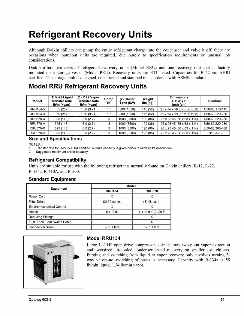
Catalog 602-2 51
Refrigerant Recovery Units Although Daikin chillers can pump the entire refrigerant charge into the condenser and valve it off, there are occasions when pumpout units are required, due purely to specification requirements or unusual job considerations.
Daikin offers two sizes of refrigerant recovery units (Model RRU) and one recovery unit that is factory mounted on a storage vessel (Model PRU). Recovery units are ETL listed. Capacities for R-22 are AHRI certified. The storage tank is designed, constructed and stamped in accordance with ASME standards.
Model RRU Refrigerant Recovery Units
Size and Specifications NOTES: 1. Transfer rate for R-22 is AHRI certified. R-134a capacity is given below in each unit's description.2. Suggested maximum chiller capacity.
Refrigerant Compatibility Units are suitable for use with the following refrigerants normally found on Daikin chillers; R-12, R-22, R-134a, R-410A, and R-500.
Standard Equipment
Equipment Model
RRU134 RRU570 Power Cord X X Filter-Driers (2) 30 cu. in. (1) 48 cu. in Electromechanical Control X X Hoses (4) 10 ft. (1) 10 ft + (2) 20 ft Reducing Fittings X 12 ft. Tank Float Switch Cable X Connection Sizes ½ in. Flare ¾ in. Flare
Model RRU134 Large 1-½ HP open drive compressor, ½-inch lines, two-point vapor extraction and oversized air-cooled condenser speed recovery on smaller size chillers. Purging and switching from liquid to vapor recovery only involves turning 3-way valves-no switching of hoses is necessary. Capacity with R-134a is 55 lb/min liquid, 1.34 lb/min vapor.
Model (1) R-22 Liquid Transfer Rate lb/m (kg/m)
(1) R 22 Vapor Transfer Rate lb/m (kg/m)
Comp. HP
(2) Chiller Tons (kW)
Weight lbs (kg)
Dimensions L x W x H Inch (cm)
Electrical
RRU134-5 55 (25) 1.56 (0.71) 1.5 300 (1050) 115 (52) 21 x 14 x 19 (53 x 36 x 68) 1/50-60/110-115 RRU134-3 55 (25) 1.56 (0.71) 1.5 300 (1050) 115 (52) 21 x 14 x 19 (53 x 36 x 68) 1/50-60/220-230 RRU570-3 325 (148) 6.0 (2.7) 3 1000 (3500) 190 (86) 26 x 25 45 (66 x 63 x 114) 1/50-60/220-230 RRU570-V 325 (148) 6.0 (2.7) 3 1000 (3500) 190 (86) 26 x 25 45 (66 x 63 x 114) 3/50-60/220-230 RRU570-R 325 (148) 6.0 (2.7) 3 1000 (3500) 190 (86) 26 x 25 45 (66 x 63 x 114) 3/50-60/360-460 RRU570-D 325 (148) 6.0 (2.7) 3 1000 (3500) 190 (86) 26 x 25 45 (66 x 63 x 114) 3/60/575
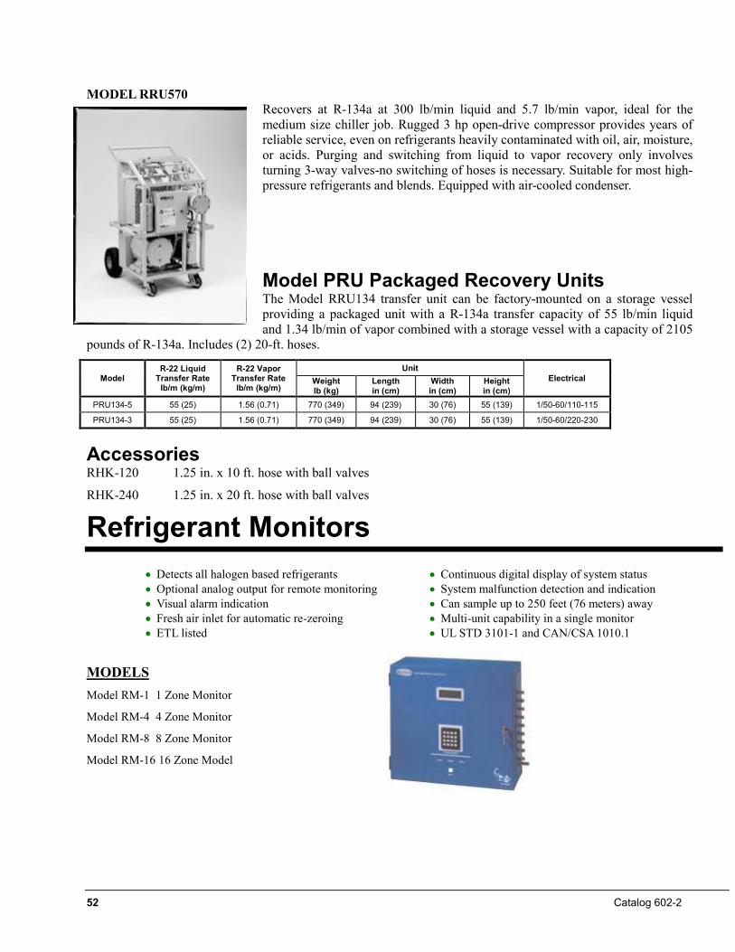
52 Catalog 602-2
MODEL RRU570 Recovers at R-134a at 300 lb/min liquid and 5.7 lb/min vapor, ideal for the medium size chiller job. Rugged 3 hp open-drive compressor provides years of reliable service, even on refrigerants heavily contaminated with oil, air, moisture, or acids. Purging and switching from liquid to vapor recovery only involves turning 3-way valves-no switching of hoses is necessary. Suitable for most high-pressure refrigerants and blends. Equipped with air-cooled condenser.
Model PRU Packaged Recovery Units The Model RRU134 transfer unit can be factory-mounted on a storage vessel providing a packaged unit with a R-134a transfer capacity of 55 lb/min liquid and 1.34 lb/min of vapor combined with a storage vessel with a capacity of 2105
pounds of R-134a. Includes (2) 20-ft. hoses.
Model R-22 Liquid
Transfer Rate lb/m (kg/m)
R-22 Vapor Transfer Rate
lb/m (kg/m)
Unit Electrical Weight
lb (kg) Length in (cm)
Width in (cm)
Height in (cm)
PRU134-5 55 (25) 1.56 (0.71) 770 (349) 94 (239) 30 (76) 55 (139) 1/50-60/110-115
PRU134-3 55 (25) 1.56 (0.71) 770 (349) 94 (239) 30 (76) 55 (139) 1/50-60/220-230
Accessories RHK-120 1.25 in. x 10 ft. hose with ball valves
RHK-240 1.25 in. x 20 ft. hose with ball valves
Refrigerant Monitors •• Detects all halogen based refrigerants •• Continuous digital display of system status •• Optional analog output for remote monitoring •• System malfunction detection and indication •• Visual alarm indication •• Can sample up to 250 feet (76 meters) away •• Fresh air inlet for automatic re-zeroing •• Multi-unit capability in a single monitor •• ETL listed •• UL STD 3101-1 and CAN/CSA 1010.1
MODELS Model RM-1 1 Zone Monitor
Model RM-4 4 Zone Monitor
Model RM-8 8 Zone Monitor
Model RM-16 16 Zone Model
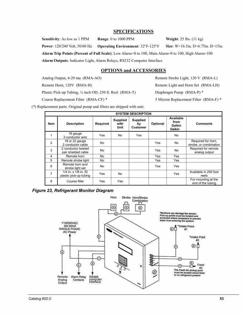
Catalog 602-2 53
SPECIFICATIONS Sensitivity: As low as 1 PPM Range: 0 to 1000 PPM Weight: 25 lbs. (11 kg)
Power: 120/240 Volt, 50/60 Hz Operating Environment: 32°F-125°F Size: W=16.5in. D=6.75in. H=15in.
Alarm Trip Points (Percent of Full Scale): Low Alarm=0 to 100, Main Alarm=0 to 100, High Alarm=100
Alarm Outputs: Indicator Light, Alarm Relays, RS232 Computer Interface
OPTIONS and ACCESSORIES Analog Output, 4-20 ma (RMA-AO) Remote Strobe Light, 120 V (RMA-L)
Remote Horn, 120V (RMA-H) Remote Light and Horn Set (RMA-LH)
Plastic Pick-up Tubing, ¼ inch OD, 250 ft. Reel (RMA-T) Diaphragm Pump (RMA-P) *
Course Replacement Filter (RMA-CF) * 5 Micron Replacement Filter (RMA-F) *
(*) Replacement parts. Original pump and filters are shipped with unit.
SYSTEM DESCRIPTION
Item Description Required Supplied
with Unit
Supplied by
Customer Optional
Available from
Daikin Daikin
Comments
1 16 gauge 3 conductor wire Yes No Yes No
2 18 or 22 gauge 2 conductor cable No Yes No Required for horn,
strobe, or combination
3 2 conductor twisted pair shielded cable No Yes No Required for remote
analog output 4 Remote horn No Yes Yes 5 Remote strobe light No Yes Yes
6 Remote horn and strobe light set No Yes Yes
7 1/4 in. x 1/8 in. ID plastic pick-up tubing Yes No Yes Available in 250 foot
reels
8 Course filter Yes Yes For mounting at the end of the tubing
Figure 23, Refrigerant Monitor Diagram
54 Catalog 602-2
Specifications SECTION 15XXX
MAGNETIC BEARING CENTRIFUGAL CHILLERS PART 1 - GENERAL
1.1 SUMMARY
A. Section includes design, performance criteria, refrigerants, controls, and installation requirements for water-cooled centrifugal chillers.
1.2 REFERENCES
A. Comply with the following codes and standards:
• AHRI 550/590 • AHRI 575 • NEC • ANSI/ASHRAE 15 • OSHA as adopted by the State • ETL • ASME Section VIII
1.3 SUBMITTALS
A. Submittals shall include the following:
1. Dimensioned plan and elevation view, including required clearances, and location of all field piping and electrical connections.
2. Summaries of all auxiliary utility requirements such as: electricity, water, air, etc. Summary shall indicate quality and quantity of each required utility.
3. Diagram of control system indicating points for field interface and field connection. Diagram shall fully depict field and factory wiring.
4. Manufacturer's certified performance data at full load plus IPLV or NPLV.
5. Installation and Operating Manuals.
1.4 QUALITY ASSURANCE
A. Regulatory Requirements: Comply with the codes and standards in Section 1.2. B. Chiller manufacturer plant shall be ISO Certified.
1.5 DELIVERY AND HANDLING
A. Chillers shall be delivered to the job site completely assembled and charged with refrigerant R134a and be shipped on skids with a weather resistant cover.
-- OR --
A. (For Type IV Knockdown) The compressor(s) and control and power panel(s) shall be removed at the factory and shipped on skids. The stripped vessel stack shall be shipped as a single piece. Discharge piping, liquid line and the compressor cooling lines shall be removed and crated. All associated wiring and piping possible will remain on the vessel stack. The unit shall be shipped without refrigerant, which must be furnished and charged by the installing contractor.
-- OR --
Catalog 602-2 55
A. (For Type V Knockdown) The unit shall be delivered to the job site completely assembled and charged with refrigerant (pumped down into condenser) and ready for field knockdown, as determined by the installing contractor.
B. Comply with the manufacturer's instructions for rigging and transporting units. Leave protective covers in place until installation.
1.6 WARRANTY
A. The chiller manufacturer's warranty shall cover parts and labor costs for the repair or replacement of defects in material or workmanship [OPTION] including refrigerant for the entire unit, for a period of one year from equipment startup or 18 months from shipment, whichever occurs first, [OPTION] and also include an additional extended warranty for (one OR two OR three OR four) years on (the entire unit) OR (on entire unit including refrigerant coverage) OR (compressor and drive train only). Warranty support shall be provided by company direct or factory authorized service permanently located near the job site.
1.7 MAINTENANCE
A. Maintenance of the chillers in accordance with manufacturer’s recommendations as published in the installation and maintenance manuals shall be the responsibility of the owner.
PART 2 - PRODUCTS
2.1 ACCEPTABLE MANUFACTURERS
A. Basis of Design - Daikin Magnitude Model WMC/WME, including the standard product features and all special features required per the plans and specifications.
B. Equal Products - Equipment manufactured by [ENTER MANUFACTURER NAME HERE] may be acceptable as an equal. Naming these products as equal does not imply that their standard construction or configuration is acceptable or meets the specifications. Equipment proposed “as equal”, must meet the specifications including all architectural, mechanical, electrical, and structural details, all scheduled performance and the job design, plans and specifications.
2.2 UNIT DESCRIPTION
A. Provide and install as shown on the plans a factory assembled and charged water-cooled packaged centrifugal chiller. Chillers shall have no more than two oil-free, magnetic bearing, semi-hermetic centrifugal compressors (no exceptions). Each compressor shall have an integrated variable-frequency drive operating in concert with inlet guide vanes for optimized full and part load efficiency. On two-compressor units, the evaporator and condenser refrigerant sides and the expansion valve shall be common and the chiller shall be capable of running on one compressor with the other compressor or any of its auxiliaries inoperable or removed.
B. [Option] Each chiller shall undergo a [one] OR [two] OR [three] OR [four] or [five] or [ten] point certified factory performance tested on an AHRI qualified test stand with water at job conditions (excluding glycol applications). A manufacture’s engineer shall oversee the testing, certify the accuracy of the computerized results, and then translates the test data onto an easy-to-read spreadsheet provided to the owner. The tests are to be run as specified in advance and are run to within AHRI tolerance of capacity and power. 50 Hz units are run tested at 60 Hz to their maximum motor power. Operating controls shall be adjusted and checked. The refrigerant charge shall be adjusted for optimum operation and recorded on the unit nameplate. Units operating with 50-Hz power shall be tested with a 50-Hz power supply. Any deviation in performance or operation shall be remedied prior to shipment and the unit retested if necessary to confirm repairs or adjustments.
--OR--
56 Catalog 602-2
B. [Option] Each chiller shall undergo a [one] OR [two] OR [three] OR [four] or [five] or [ten] point certified witness performance test on an AHRI qualified test stand with water at job conditions (excluding glycol applications). A manufacture’s engineer shall oversee the testing in the presence of the owner or owner’s representative, certify the accuracy of the computerized results, and then translates the test data onto an easy-to-read spreadsheet provided to the owner. The tests are to be run as specified in advance and are run to within AHRI tolerance of capacity and power. 50 Hz units are run tested at 60 Hz to their maximum motor power. Operating controls shall be adjusted and checked. The refrigerant charge shall be adjusted for optimum operation and recorded on the unit nameplate. Units operating with 50-Hz power shall be tested with a 50-Hz power supply. Any deviation in performance or operation shall be remedied prior to shipment and the unit retested if necessary to confirm repairs or adjustments.
2.3 DESIGN REQUIREMENTS
General: Provide a complete water-cooled, semi-hermetic oil-free centrifugal compressor water chiller as specified herein. The unit shall be provided according to standards indicated in Section 1.2. In general, unit shall consist of one or two magnetic bearing, completely oil-free centrifugal compressors, refrigerant, condenser and evaporator, and control systems including integrated variable frequency drive, operating controls and equipment protection controls. Chillers shall be designed to operate within an ambient temperature range of 40ºF to 104ºF with a maximum humidity of 95% (non-condensing) and shall be charged with refrigerant HFC-134a. If manufacturer offers a chiller using any HCFC refrigerant that is subject to phase out by the Montreal Protocol or the U.S. Clean Air Act, manufacturer shall provide, in writing, documentation signed by an officer of the company assuring refrigerant availability and price schedule for a 20-year period.
A. The entire chiller system, including all pressure vessels, shall remain above atmospheric pressure during all operating conditions and during shut down to ensure that non-condensables and moisture do not contaminate the refrigerant and chiller system. If any portion of the chiller system is below atmospheric pressure during either operation or shut down, the manufacturer shall include, at no charge:
1. Purge System
i. A complete purge system capable of removing non-condensables and moisture during operation and shut-down. The system shall consist of an air cooled condensing unit, purge condensing tank, pumpout compressor, and control system.
ii. A dedicated condensing unit shall be provided with the purge system to provide a cooling source whether or not the chiller is running. The condensing unit shall provide a low purge coil temperature to result in a maximum loss of 0.1 pounds of refrigerant per pound of purged air.
iii. The purge system shall be connected to a 100% reclaim device.
iv. A 20-year purge maintenance agreement that provides parts, labor, and all preventative maintenance required by the manufacturer’s operating and maintenance instructions.
2. Annual Oil/Refrigerant Analysis
i. The manufacturer shall also include at no charge for a period of 20 years an annual oil and refrigerant analysis report to identify chiller contamination due to vacuum leaks. If the analysis identifies water, acid, or other contaminant levels higher than specified by the manufacturer, the oil and/or refrigerant must be replaced or returned to the manufacturer’s original specification at no cost to the owner.
3. Shell Pressurization System
i. The manufacturer shall include a factory-installed and wired system that will enable service personnel to readily elevate the vessel pressure during shutdown to facilitate leak testing.
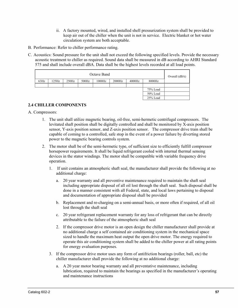
Catalog 602-2 57
ii. A factory mounted, wired, and installed shell pressurization system shall be provided to keep air out of the chiller when the unit is not in service. Electric blanket or hot water circulation system are both acceptable.
B. Performance: Refer to chiller performance rating.
C. Acoustics: Sound pressure for the unit shall not exceed the following specified levels. Provide the necessary acoustic treatment to chiller as required. Sound data shall be measured in dB according to AHRI Standard 575 and shall include overall dBA. Data shall be the highest levels recorded at all load points.
Octave Band Overall (dBA) 63Hz 125Hz 250Hz 500Hz 1000Hz 2000Hz 4000Hz 8000Hz
75% Load 50% Load 25% Load
2.4 CHILLER COMPONENTS
A. Compressors:
1. The unit shall utilize magnetic bearing, oil-free, semi-hermetic centrifugal compressors. The levitated shaft position shall be digitally controlled and shall be monitored by X-axis position sensor, Y-axis position sensor, and Z-axis position sensor. The compressor drive train shall be capable of coming to a controlled, safe stop in the event of a power failure by diverting stored power to the magnetic bearing controls system.
2. The motor shall be of the semi-hermetic type, of sufficient size to efficiently fulfill compressor horsepower requirements. It shall be liquid refrigerant cooled with internal thermal sensing devices in the stator windings. The motor shall be compatible with variable frequency drive operation.
1. If unit contains an atmospheric shaft seal, the manufacturer shall provide the following at no additional charge:
a. 20 year warranty and all preventive maintenance required to maintain the shaft seal including appropriate disposal of all oil lost through the shaft seal. Such disposal shall be done in a manner consistent with all Federal, state, and local laws pertaining to disposal and documentation of appropriate disposal shall be provided
b. Replacement and re-charging on a semi-annual basis, or more often if required, of all oil lost through the shaft seal
c. 20 year refrigerant replacement warranty for any loss of refrigerant that can be directly attributable to the failure of the atmospheric shaft seal
2. If the compressor drive motor is an open design the chiller manufacturer shall provide at no additional charge a self contained air conditioning system in the mechanical space sized to handle the maximum heat output the open drive motor. The energy required to operate this air conditioning system shall be added to the chiller power at all rating points for energy evaluation purposes.
3. If the compressor drive motor uses any form of antifriction bearings (roller, ball, etc) the chiller manufacturer shall provide the following at no additional charge:
a. A 20 year motor bearing warranty and all preventative maintenance, including lubrication, required to maintain the bearings as specified in the manufacturer’s operating and maintenance instructions
58 Catalog 602-2
b. At start up a three axis vibration analysis and written report which establishes a baseline of motor bearing condition.
c. An annual three axis vibration analysis and written report to indicate the trend of bearing wear.
3. The chiller shall be equipped with an integrated Variable Frequency Drive (VFD) to automatically regulate compressor speed in response to cooling load and the compressor pressure lift requirement. Movable inlet guide vanes and variable compressor speed acting together, shall provide unloading. The chiller controls shall coordinate compressor speed and guide vane position to optimize chiller efficiency.
4. [OPTIONAL) Each compressor shall be equipped with a field-mounted harmonic filter.
5. Each compressor circuit shall be equipped with a line reactor to help protect against incoming power surges and help reduce harmonic distortion.
B. Evaporator and Condenser:
The evaporator and condenser shall be separate vessels of the shell-and-tube type, designed, constructed, tested and stamped according to the requirements of the ASME Code, Section VIII. Regardless of the operating pressure, the refrigerant side of each vessel will bear the ASME stamp indicating compliance with the code and indicating a test pressure of 1.1 times the working pressure, but not less than 100 psig. The tubes shall be individually replaceable and secured to the intermediate supports without rolling or expanding to facilitate replacement if required.
1. The evaporator shall be flooded type with [0.025 in.] OR [0.028 in.] OR [0.035 in.] wall copper internally and externally enhanced tubes rolled into carbon steel tubesheets. The water side shall be designed for a minimum of [150 psig] OR [300 psig]. The refrigerant side shall be designed for a minimum of 200 psi. Provide intermediate tube supports at a maximum of 24 inch spacing. The heads shall be [carbon steel] OR [epoxy-coated steel]. Water connections shall be [grooved suitable for Victaulic couplings] OR [flanged connections]. The evaporator shall have [dished heads with valved drain and vent connections] OR [shall be equipped with marine water boxes with removable covers and vent and drain connections]. The evaporator shall have [right-hand] OR [left-hand] connections when looking at the unit control panel.
2. The condenser shall have [(0.025 in) OR (0.028 in.) OR (0.035 in.) wall copper] OR [(0.028 in.) or (0.035 in.) wall 90-10 cupro-nickel] internally and externally enhanced tubes rolled into carbon steel. Water connections shall be [grooved suitable for Victaulic couplings] OR [flanged]. The water side shall be designed for a minimum of [150 psig] OR [300 psig]. The refrigerant side shall be designed for a minimum of 200 psi. Provide intermediate tube supports at a maximum of 24 inch spacing. The condenser shall have [dished heads with valved drain and vent connections] OR [shall be equipped with marine water boxes with removable covers and vent and drain connections]. The heads shall be [carbon steel] OR [epoxy-coated steel]. The condenser shall have [right-hand] OR [left-hand] connections when looking at the unit control panel.
3. Provide sufficient isolation valves and condenser volume to hold the full unit refrigerant charge the condenser at 90ºF in accordance with ANSIASHRAE 15.A during servicing or provide a separate pumpout system and storage tank sufficient to hold the charge of the largest unit being furnished.
4. An electronic expansion valve shall control refrigerant flow to the evaporator. Fixed orifice devices or float controls with hot gas bypass are not acceptable because of inefficient control at low load conditions. The liquid line shall have moisture indicating sight glass.
5. Re-seating type spring loaded pressure relief valves according to ASHRAE-15 safety code shall be furnished. The evaporator shall be provided with single or multiple valves. The condenser shall be provided with dual relief valves equipped with a transfer valve so one relief valve can be removed for testing or replacement without loss of refrigerant or removal of refrigerant from the condenser.
Catalog 602-2 59
Rupture disks are not acceptable. If rupture disks are required on negative pressure units to prevent air and moisture ingress, then factory mounted spring loaded pressure relief valves shall be provided in series with the rupture disks to contain the remaining refrigerant in the event of vessel over-pressurization. The space between the rupture disk and the relief valve shall include a suitable telltale indicator integrated into the chiller control system to alert the operator that a potential safety issue exists in the pressure relief system.
6. [OPTIONAL] The evaporator, including water heads, suction line, and any other component or part of a component subject to condensing moisture shall be insulated with UL recognized [3/4 inch] OR [1 ½ inch] closed cell insulation. All joints and seams shall be carefully sealed to form a vapor barrier.
7. Provide factory-mounted and wired, thermal-dispersion water flow switches on each vessel to prevent unit operation with no or low water flow. Paddle and pressure differential type switches are not acceptable due to high rates of failure and false indications from these types of flow indicators.
C. Long Term Reliability
1. All compressor/motor designs that require oil to lubricate their respective roller/ball bearing system must denote exactly how many gallons of oil are required for safe operation. The manufacturer must then provide the engineer and owner with a real world energy analysis showing the energy degradation over time due oil contamination of heat transfer surfaces.
2. Chillers containing oil shall include at no additional charge a 10 year parts and labor warranty on all oil system components including:
• Pumps • Starter • Piping • Tank
• Heater • Cooler • Controls • Valves
3. Manufacturer shall be responsible for covering all costs associated with annual oil and oil filter changes plus oil analysis as required
D. Vibration Isolation
1. Provide neoprene waffle-type vibration isolators for each corner of the unit.
E. Power Connections
1. Power connection shall be [single point to a factory-mounted disconnect switch] OR [multipoint to each compressor power panel on two-compressor units].
F. Chiller Control
1. The unit shall have a microprocessor-based control system consisting of a 15-inch VGA touch-screen operator interface and a unit controller.
2. The touch-screen shall display the unit operating parameters, accept setpoint changes (multi-level password protected) and be capable of resetting faults and alarms. The following parameters shall be displayed on the home screen and also as trend curves on the trend screen:
• Entering and leaving chilled water temperatures
• Entering and leaving condenser water temperatures
• Evaporator saturated refrigerant pressure
• Condenser saturated refrigerant pressure
• Percent of 100% speed (per compressor)
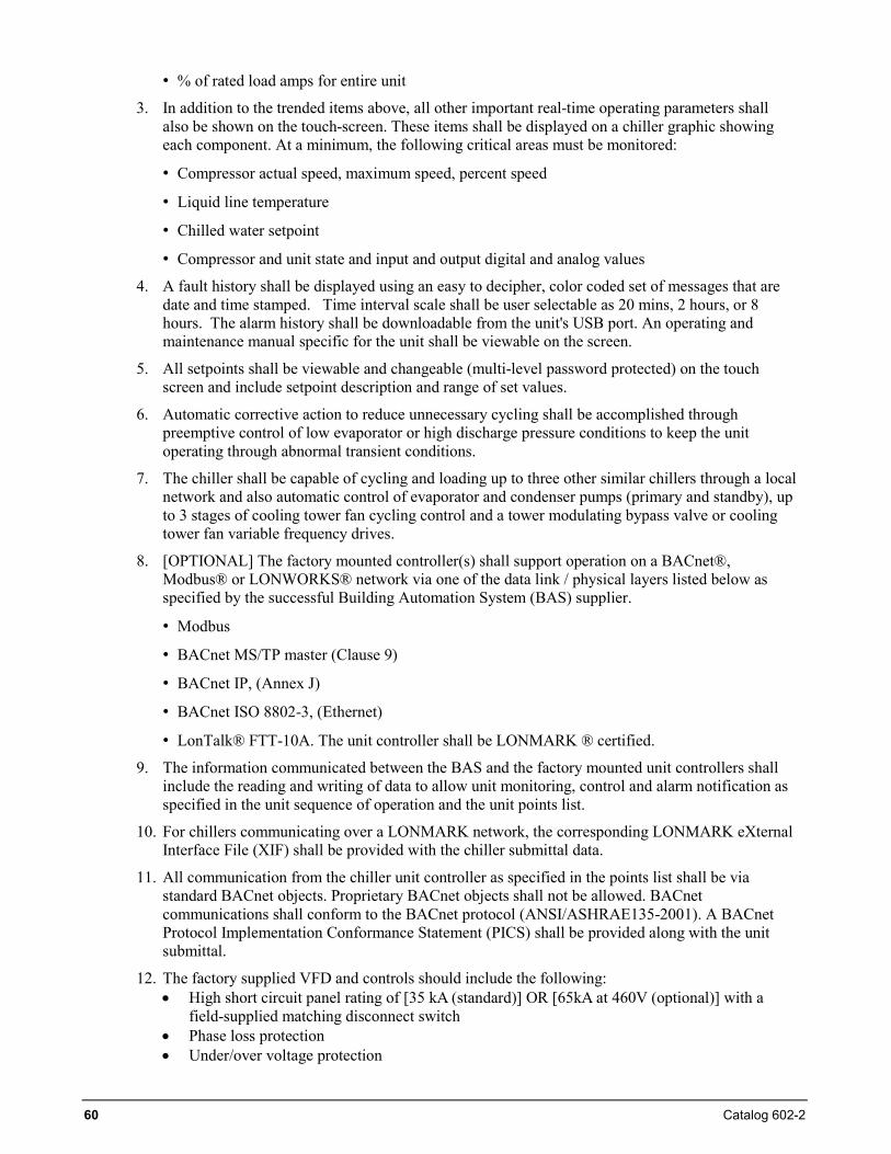
60 Catalog 602-2
• % of rated load amps for entire unit
3. In addition to the trended items above, all other important real-time operating parameters shall also be shown on the touch-screen. These items shall be displayed on a chiller graphic showing each component. At a minimum, the following critical areas must be monitored:
• Compressor actual speed, maximum speed, percent speed
• Liquid line temperature
• Chilled water setpoint
• Compressor and unit state and input and output digital and analog values
4. A fault history shall be displayed using an easy to decipher, color coded set of messages that are date and time stamped. Time interval scale shall be user selectable as 20 mins, 2 hours, or 8 hours. The alarm history shall be downloadable from the unit's USB port. An operating and maintenance manual specific for the unit shall be viewable on the screen.
5. All setpoints shall be viewable and changeable (multi-level password protected) on the touch screen and include setpoint description and range of set values.
6. Automatic corrective action to reduce unnecessary cycling shall be accomplished through preemptive control of low evaporator or high discharge pressure conditions to keep the unit operating through abnormal transient conditions.
7. The chiller shall be capable of cycling and loading up to three other similar chillers through a local network and also automatic control of evaporator and condenser pumps (primary and standby), up to 3 stages of cooling tower fan cycling control and a tower modulating bypass valve or cooling tower fan variable frequency drives.
8. [OPTIONAL] The factory mounted controller(s) shall support operation on a BACnet®, Modbus® or LONWORKS® network via one of the data link / physical layers listed below as specified by the successful Building Automation System (BAS) supplier.
• Modbus
• BACnet MS/TP master (Clause 9)
• BACnet IP, (Annex J)
• BACnet ISO 8802-3, (Ethernet)
• LonTalk® FTT-10A. The unit controller shall be LONMARK ® certified.
9. The information communicated between the BAS and the factory mounted unit controllers shall include the reading and writing of data to allow unit monitoring, control and alarm notification as specified in the unit sequence of operation and the unit points list.
10. For chillers communicating over a LONMARK network, the corresponding LONMARK eXternal Interface File (XIF) shall be provided with the chiller submittal data.
11. All communication from the chiller unit controller as specified in the points list shall be via standard BACnet objects. Proprietary BACnet objects shall not be allowed. BACnet communications shall conform to the BACnet protocol (ANSI/ASHRAE135-2001). A BACnet Protocol Implementation Conformance Statement (PICS) shall be provided along with the unit submittal.
12. The factory supplied VFD and controls should include the following: • High short circuit panel rating of [35 kA (standard)] OR [65kA at 460V (optional)] with a
field-supplied matching disconnect switch • Phase loss protection • Under/over voltage protection
Catalog 602-2 61
• [OPTIONAL] Ground Fault Protection to reduce the arcing ground fault damage from line-to-ground fault currents less than those required for conductor protection
• [OPTIONAL] EMI filters to reduce radio frequency interference
13. Energy saving software logic shall at a minimum offer the following • User programmable compressor soft loading • Chilled water reset • Demand limit control • Staging options lead lag between multiple compressors on a single chiller or up to two other
similar chillers. • Plotting of historic trends for optimizing efficiency
2.5. OPTIONAL ITEMS
The following optional items shall be furnished: 1. [Open] OR [Closed] export crate 2. Pumpout unit, with or without storage vessel 3. Refrigerant monitor 4. OSHPD Certification: The chiller shall be OSHPD Pre-Approved per OSP–0116-10 and be so labeled. The
chiller shall meet a minimum seismic design spectral response acceleration of 1.60 SDS. The chiller must be mounted to a rigid base and may use neoprene waffle vibration pads.
5. IBC Certification: The chiller shall be certified to the following codes and standards; 2009 IBC, 2010 CBC, ICC-ES AC-156, ASCE 7-05. The chiller must be mounted to a rigid base and may use neoprene waffle vibration pads.
PART 3 - EXECUTION
3.1 INSTALLATION
A. Installing contractor to: 1. Install per manufacturer's requirements, shop drawings, and contract documents. 2. Adjust chiller alignment on foundations, or subbases as called for on drawings. 3. Arrange piping to allow for dismantling to permit head removal and tube cleaning. 4. Coordinate electrical installation with electrical contractor. 5. Coordinate controls with control contractor. 6. Provide all material required for a fully operational and functional chiller. 7 Install unit in a dry indoor location consistent with NEMA 1 design.
3.2 START-UP
A. Factory Start-Up Services: Provide for as long a time as is necessary to ensure proper operation of the unit, but in no case for less than two full working days. During the period of start-up, the start-up technician shall instruct the owner's representative in proper care and operation of the unit.


© 2013 Daikin Applied • (800)432-1342 • www.DaikinApplied.com Catalog 602-2 (5/13)
Daikin Training and Development
Now that you have made an investment in modern, efficient Daikin equipment, its care should be a high priority. For training information on all Daikin HVAC products, please visit us at www.DaikinApplied.com and click on training, or call 540-248-9646 and ask for the Training Department.
Warranty
All Daikin equipment is sold pursuant to Daikin standard terms and conditions of sale, including Limited Product Warranty. Consult your local Daikin Representative for warranty details. To find your local DaikinRepresentative, go to www.DaikinApplied.com .
This document contains the most current product information as of this printing. For the most up-to-date product information, please go to www.DaikinApplied.com .