Embed Size (px)
Citation preview
Catalog 220RoofPak® Applied Rooftop Systemswith Energy Recovery WheelsPackaged Heating and Cooling Units Type RFS/RPS – 15 to 75 Tons Type RDT – 45 to 75 Tons
Rooftop Air Handlers Type RAH/RDS – 4,000 to 30,000 CFM
MEA368-93-N
CAT 220 • ROOFPAK APPLIED ROOFTOPS 2 www.DaikinApplied.com
Table of ConTenTs
DesignFlow, Hi-F, MicroTech, Protocol Selectability, RoofPak, SelectTools, SpeedTrol, SuperMod, UltraSeal, and VaneTrol are trademarks Daikin Applied Americas.
Microsoft is a registered trademark of Microsoft Corporation. Windows is a trademark of Microsoft Corporation. © 2016 Daikin Applied. All rights reserved throughout the world.
Table of ConTenTs
Introduction . . . . . . . . . . . . . . . . . . . . . . . . . . . . . . . . . . 3Daikin Energy Recovery Systems. . . . . . . . . . . . . . . . 3Factory-Installed and Tested Package . . . . . . . . . . . . 3
Roofpak Energy Recovery Systems . . . . . . . . . . . . . . 4Energy Savings . . . . . . . . . . . . . . . . . . . . . . . . . . . . . . 4Satisfies ASHRAE 90.1-2004 Energy Recovery Requirements . . . . . . . . . . . . . . . . . . . . . . . . . . . . . . . 4A Complete, Factory-Tested Package. . . . . . . . . . . . . 4Enthalpy Wheel Design. . . . . . . . . . . . . . . . . . . . . . . . 4Return/Exhaust Air Fan . . . . . . . . . . . . . . . . . . . . . . . . 5Handling Moisture . . . . . . . . . . . . . . . . . . . . . . . . . . . . 5Summer Performance . . . . . . . . . . . . . . . . . . . . . . . . . 5First Cost and Operating Cost Reductions . . . . . . . . . 6Two Arrangements Offered . . . . . . . . . . . . . . . . . . . . . 6Parallel Air Paths on Energy Recovery Wheel Applications. . . . . . . . . . . . . . . . . . . . . . . . . . . . . . . . . 7Enthalpy Wheel Controls and Wiring . . . . . . . . . . . . . 8Energy Recovery Bypass Damper Control . . . . . . . . . 8
Application Considerations . . . . . . . . . . . . . . . . . . . . . 9General . . . . . . . . . . . . . . . . . . . . . . . . . . . . . . . . . . . . 9Unit Location . . . . . . . . . . . . . . . . . . . . . . . . . . . . . . . . 9Split Units . . . . . . . . . . . . . . . . . . . . . . . . . . . . . . . . . . 9Curb Installation . . . . . . . . . . . . . . . . . . . . . . . . . . . . . 9Acoustical Considerations. . . . . . . . . . . . . . . . . . . . . 10Ductwork . . . . . . . . . . . . . . . . . . . . . . . . . . . . . . . . . . 11Filters . . . . . . . . . . . . . . . . . . . . . . . . . . . . . . . . . . . . 11Variable Air Volume Application. . . . . . . . . . . . . . . . . 12Fan Operating Range . . . . . . . . . . . . . . . . . . . . . . . . 12Altitude Adjustments . . . . . . . . . . . . . . . . . . . . . . . . . 12Condenser Performance . . . . . . . . . . . . . . . . . . . . . . 13Wheel Performance . . . . . . . . . . . . . . . . . . . . . . . . . 13Furnace Performance . . . . . . . . . . . . . . . . . . . . . . . 13
Unit Selection . . . . . . . . . . . . . . . . . . . . . . . . . . . . . . . 14
Physical Data . . . . . . . . . . . . . . . . . . . . . . . . . . . . . . . 18Cooling Capacity Data . . . . . . . . . . . . . . . . . . . . . . . . 20Heating Capacity Data . . . . . . . . . . . . . . . . . . . . . . . . 28
Gas Heat . . . . . . . . . . . . . . . . . . . . . . . . . . . . . . . . . . 28Electric Heat . . . . . . . . . . . . . . . . . . . . . . . . . . . . . . . 30Steam and Hot Water Heat . . . . . . . . . . . . . . . . . . . 31
Component Pressure Drops . . . . . . . . . . . . . . . . . . . 32Energy Recovery Module Air Pressure Drop Fan Loss . . . . . . . . . . . . . . . . . . . . . . . . . . . . . . . . . . 32
Fan Performance Data . . . . . . . . . . . . . . . . . . . . . . . . 35Supply Fans . . . . . . . . . . . . . . . . . . . . . . . . . . . . . . . 35Airfoil Return Fans . . . . . . . . . . . . . . . . . . . . . . . . . . 40
Dimensional Data . . . . . . . . . . . . . . . . . . . . . . . . . . . . 41Section Options and Locations . . . . . . . . . . . . . . . . 41Electrical Knockout Locations . . . . . . . . . . . . . . . . . . 46Drain and Air Connection Locations . . . . . . . . . . . . . 47Piping Entrance Locations . . . . . . . . . . . . . . . . . . . . 48
Roof Curbs . . . . . . . . . . . . . . . . . . . . . . . . . . . . . . . . . 49Recommended Clearances . . . . . . . . . . . . . . . . . . . . 52
Service Clearance. . . . . . . . . . . . . . . . . . . . . . . . . . . 52Overhead Clearance . . . . . . . . . . . . . . . . . . . . . . . . . 52Ventilation Clearance . . . . . . . . . . . . . . . . . . . . . . . . 52
Electrical Data . . . . . . . . . . . . . . . . . . . . . . . . . . . . . . . 53Supply Power Wiring. . . . . . . . . . . . . . . . . . . . . . . . . 56
Weight Data . . . . . . . . . . . . . . . . . . . . . . . . . . . . . . . . . 57Unit Weights . . . . . . . . . . . . . . . . . . . . . . . . . . . . . . . 57Fan Motor Weights . . . . . . . . . . . . . . . . . . . . . . . . . . 58Roof Curb Weights . . . . . . . . . . . . . . . . . . . . . . . . . . 61
Engineering Guide Specification . . . . . . . . . . . . . . . 62
InTroduCTIon
www.DaikinApplied.com 3 CAT 220 • ROOFPAK APPLIED ROOFTOPS
InTroduCTIon
Daikin Energy Recovery SystemsOur energy recovery device transfers both heat and moisture energy between the exhaust and ventilation air. In doing so, it conditions the incoming ventilation air. This total energy device offers a cost-effective and efficient method for containing energy costs while meeting the ventilation requirements of ASHRAE Standard 62.1-1999.
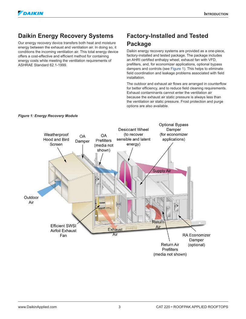
Factory-Installed and Tested PackageDaikin energy recovery systems are provided as a one-piece, factory-installed and tested package. The package includes an AHRI certified enthalpy wheel, exhaust fan with VFD, prefilters, and, for economizer applications, optional bypass dampers and controls (see Figure 1). This helps to eliminate field coordination and leakage problems associated with field installation.
The outdoor and exhaust air flows are arranged in counterflow for better efficiency, and to reduce field cleaning requirements. Exhaust contaminants cannot enter the ventilation air because the exhaust air static pressure is always less than the ventilation air static pressure. Frost protection and purge options are also available.
Figure 1: Energy Recovery Module
CAT 220 • ROOFPAK APPLIED ROOFTOPS 4 www.DaikinApplied.com
roofpak energy reCovery sysTems
roofpak energy reCovery sysTems
Energy SavingsDaikin energy wheels normally recover 70–75% both sensible and latent energy. The result can be considerable energy savings:
• They provide twice as much summer energy recovery as sensible only alternatives such as plate frame heat exchangers and run-around loops.
• Energy recovery increases the air conditioning capacity by 25% if minimum outdoor air design is 33%. Therefore, a 75 ton unit with energy recovery provides about 90 tons of cooling capacity. The cost savings on mechanical heating and cooling components offset the additional cost of energy recovery.
• Winter humidification energy costs may be cut up to 60%. • Winter latent energy recovery lowers the dew point of
exhaust air, compared to sensible only alternatives and allows frost-free operation to lower ambient temperatures.
Satisfies ASHRAE 90.1-2004 Energy Recovery Requirements
• ASHRAE 90.1-2004 usually requires energy recovery if the design requires more than 5000 total CFM and more than 70% minimum outdoor air.
• The Daikin energy recovery effectiveness exceeds ASHRAE 90.1-2004 requirements.
A Complete, Factory-Tested PackageOutdoor and Return Air Prefilters2" pre-filters are provided in both the outdoor and return air, to minimize the need for cleaning the wheel.
AHRI and UL ConformanceThe Daikin energy recovery wheel is AHRI certified for performance and UL recognized for safety.
Integrated Cooling, Heating and Recovery ControlMechanical heating and cooling are supplied as necessary to supplement the wheel and maintain space conditions.
Free CoolingUnits with economizers include bypass dampers that are opened when “free cooling” is available. The wheel is simultaneously turned OFF.
Proper ExhaustExhaust fan speed is controlled for proper exhaust, using a factory installed Variable Frequency Drive (VFD) and space building pressure sensor.
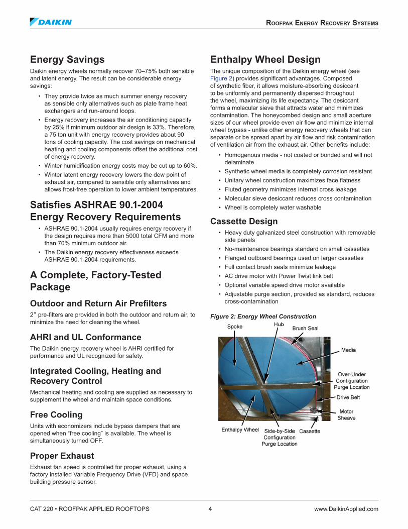
Enthalpy Wheel DesignThe unique composition of the Daikin energy wheel (see Figure 2) provides significant advantages. Composed of synthetic fiber, it allows moisture-absorbing desiccant to be uniformly and permanently dispersed throughout the wheel, maximizing its life expectancy. The desiccant forms a molecular sieve that attracts water and minimizes contamination. The honeycombed design and small aperture sizes of our wheel provide even air flow and minimize internal wheel bypass - unlike other energy recovery wheels that can separate or be spread apart by air flow and risk contamination of ventilation air from the exhaust air. Other benefits include:
• Homogenous media - not coated or bonded and will not delaminate
• Synthetic wheel media is completely corrosion resistant • Unitary wheel construction maximizes face flatness • Fluted geometry minimizes internal cross leakage • Molecular sieve desiccant reduces cross contamination • Wheel is completely water washable
Cassette Design• Heavy duty galvanized steel construction with removable
side panels • No-maintenance bearings standard on small cassettes • Flanged outboard bearings used on larger cassettes • Full contact brush seals minimize leakage • AC drive motor with Power Twist link belt • Optional variable speed drive motor available • Adjustable purge section, provided as standard, reduces
cross-contamination
Figure 2: Energy Wheel Construction
roofpak energy reCovery sysTems
www.DaikinApplied.com 5 CAT 220 • ROOFPAK APPLIED ROOFTOPS
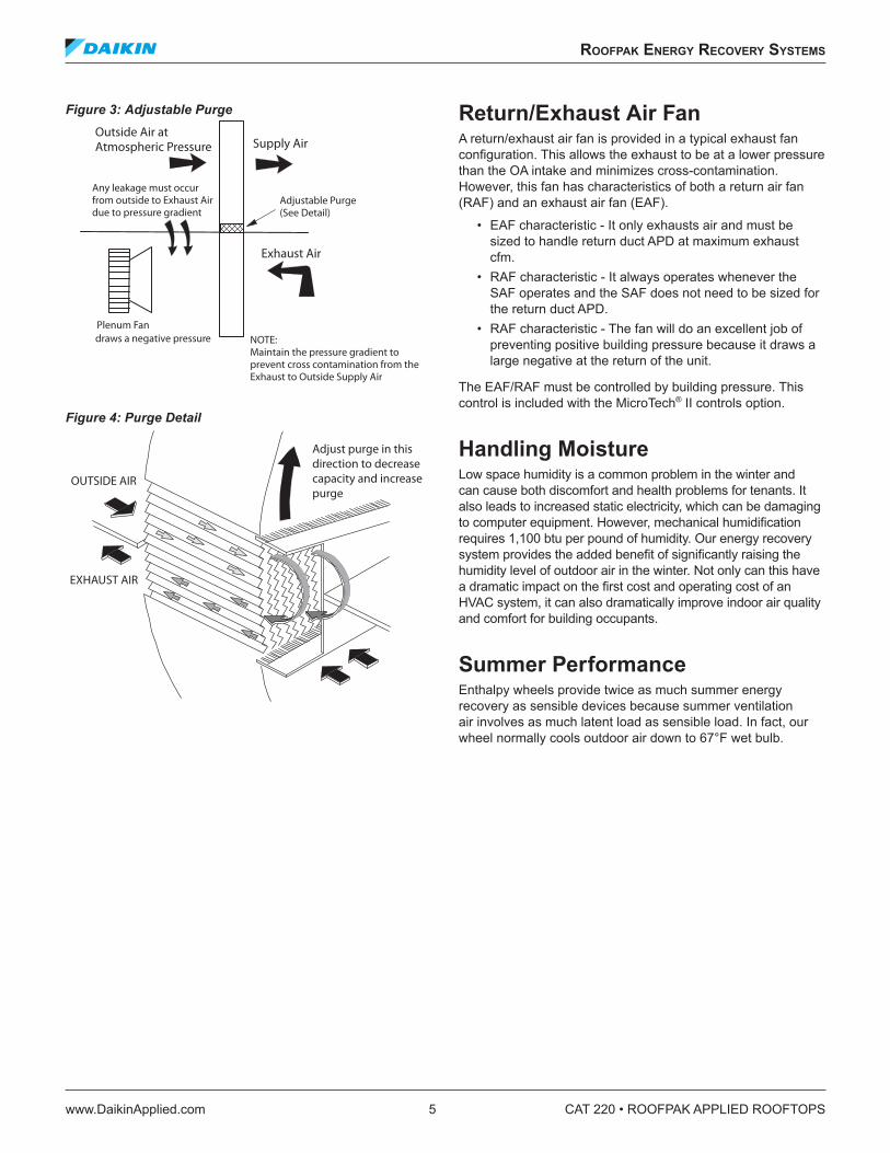
Figure 3: Adjustable Purge
Figure 4: Purge Detail
Return/Exhaust Air FanA return/exhaust air fan is provided in a typical exhaust fan configuration. This allows the exhaust to be at a lower pressure than the OA intake and minimizes cross-contamination. However, this fan has characteristics of both a return air fan (RAF) and an exhaust air fan (EAF).
• EAF characteristic - It only exhausts air and must be sized to handle return duct APD at maximum exhaust cfm.
• RAF characteristic - It always operates whenever the SAF operates and the SAF does not need to be sized for the return duct APD.
• RAF characteristic - The fan will do an excellent job of preventing positive building pressure because it draws a large negative at the return of the unit.
The EAF/RAF must be controlled by building pressure. This control is included with the MicroTech® II controls option.
Handling MoistureLow space humidity is a common problem in the winter and can cause both discomfort and health problems for tenants. It also leads to increased static electricity, which can be damaging to computer equipment. However, mechanical humidification requires 1,100 btu per pound of humidity. Our energy recovery system provides the added benefit of significantly raising the humidity level of outdoor air in the winter. Not only can this have a dramatic impact on the first cost and operating cost of an HVAC system, it can also dramatically improve indoor air quality and comfort for building occupants.
Summer PerformanceEnthalpy wheels provide twice as much summer energy recovery as sensible devices because summer ventilation air involves as much latent load as sensible load. In fact, our wheel normally cools outdoor air down to 67°F wet bulb.
Any leakage must occurfrom outside to Exhaust Airdue to pressure gradient
Supply AirOutside Air atAtmospheric Pressure
Exhaust Air
Adjustable Purge(See Detail)
Plenum Fandraws a negative pressure NOTE:
Maintain the pressure gradient toprevent cross contamination from theExhaust to Outside Supply Air
OUTSIDE AIR
EXHAUST AIR
Adjust purge in thisdirection to decreasecapacity and increasepurge
CAT 220 • ROOFPAK APPLIED ROOFTOPS 6 www.DaikinApplied.com
roofpak energy reCovery sysTems
First Cost and Operating Cost ReductionsThe charts below illustrate typical energy cost savings from the Daikin RoofPak Energy Recovery System. First cost savings result because the system is factory-installed and tested, eliminating the need for field design, installation and coordination. Because less mechanical cooling is needed, the cooling system can be downsized for additional first cost savings. This also can reduce the unit’s electrical requirement, further reducing installed costs.
Table 1: Typical Annual Energy Savings per 10,000 cfm of Ventilation Air with Daikin Energy Recovery Wheel* Minneapolis Phoenix Miami Dallas N .Y .C . Atlanta Chicago
With Winter Humidification $6,609.00 $4,605.00 $8,048.00 $5,545.00 $5,374.00 $4,738.00 $6,010.00
Without Winter Humidification $5,359.00 $4,579.00 $8,048.00 $5,381.00 $4,625.00 $4,363.00 $5,041.00
* Based on gas fired unit, 4,000 hours, $0.10 per KWHR and $0.50 per Therm)
Table 2: Typical Payback (in years) for Daikin Energy Recovery Wheel* Minneapolis Phoenix Miami Dallas N .Y .C . Atlanta Chicago
With Winter Humidification 1.2 – 2.6 2.6 – 7.4 0.7 – 2.7 1.8 – 5.2 2.0 – 6.1 2.6 – 7.1 1.5 – 4.1
Without Winter Humidification 1.9 – 4.9 2.6 – 7.4 0.7 – 2.7 1.9 – 5.4 2.6 – 7.1 2.9 – 7.3 2.1 – 6.0
* Based on gas fired unit, 4,000 hours, $0.10 per KWHR and $0.50 per Therm)
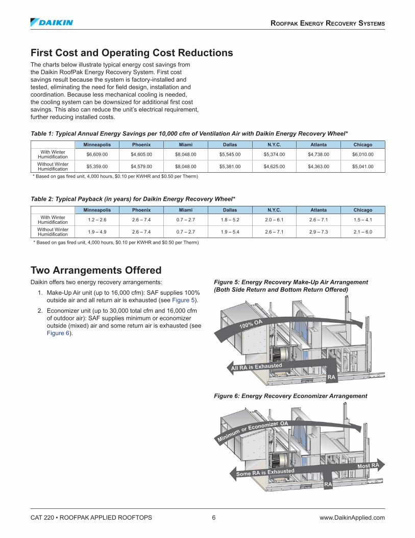
Two Arrangements OfferedDaikin offers two energy recovery arrangements:
1. Make-Up Air unit (up to 16,000 cfm): SAF supplies 100% outside air and all return air is exhausted (see Figure 5).
2. Economizer unit (up to 30,000 total cfm and 16,000 cfm of outdoor air): SAF supplies minimum or economizer outside (mixed) air and some return air is exhausted (see Figure 6).
Figure 5: Energy Recovery Make-Up Air Arrangement (Both Side Return and Bottom Return Offered)
Figure 6: Energy Recovery Economizer Arrangement
roofpak energy reCovery sysTems
www.DaikinApplied.com 7 CAT 220 • ROOFPAK APPLIED ROOFTOPS
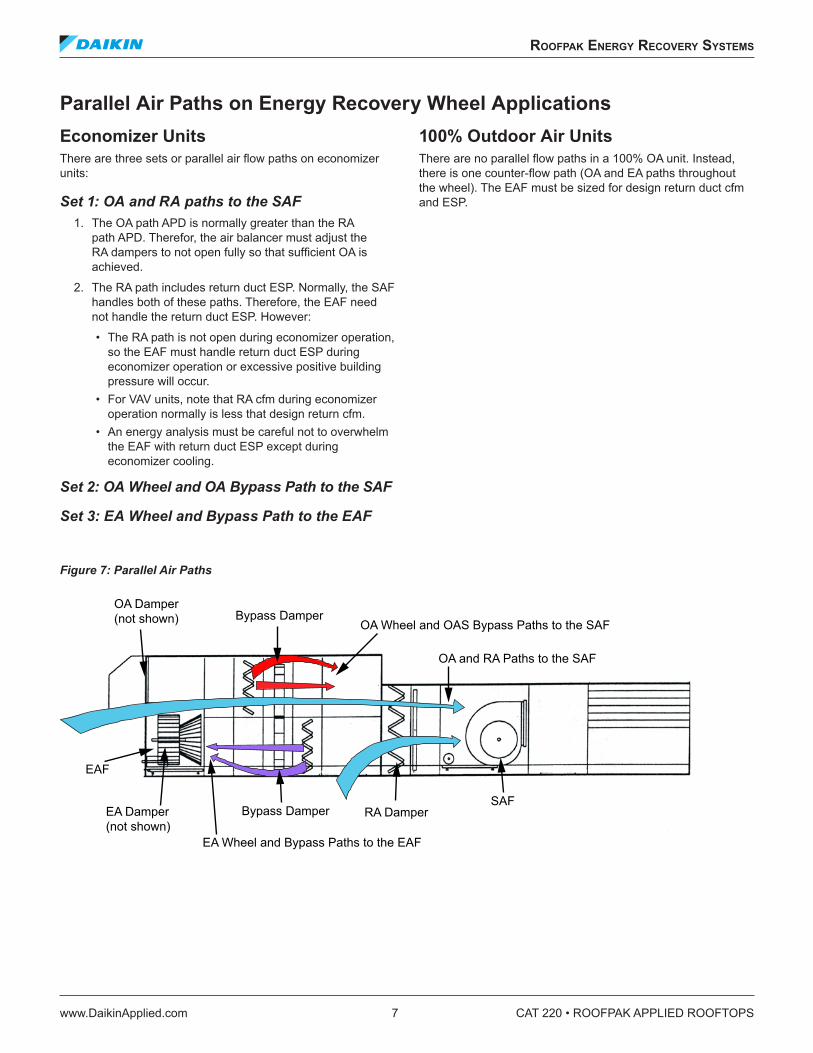
Parallel Air Paths on Energy Recovery Wheel ApplicationsEconomizer UnitsThere are three sets or parallel air flow paths on economizer units:
Set 1: OA and RA paths to the SAF 1. The OA path APD is normally greater than the RA
path APD. Therefor, the air balancer must adjust the RA dampers to not open fully so that sufficient OA is achieved.
2. The RA path includes return duct ESP. Normally, the SAF handles both of these paths. Therefore, the EAF need not handle the return duct ESP. However:
• The RA path is not open during economizer operation, so the EAF must handle return duct ESP during economizer operation or excessive positive building pressure will occur.
• For VAV units, note that RA cfm during economizer operation normally is less that design return cfm.
• An energy analysis must be careful not to overwhelm the EAF with return duct ESP except during economizer cooling.
Set 2: OA Wheel and OA Bypass Path to the SAF
Set 3: EA Wheel and Bypass Path to the EAF
100% Outdoor Air Units There are no parallel flow paths in a 100% OA unit. Instead, there is one counter-flow path (OA and EA paths throughout the wheel). The EAF must be sized for design return duct cfm and ESP.
Figure 7: Parallel Air Paths
OA Damper(not shown) Bypass Damper
OA Wheel and OAS Bypass Paths to the SAF
EA Wheel and Bypass Paths to the EAF
OA and RA Paths to the SAF
Bypass DamperEA Damper(not shown)
SAF
EAF
RA Damper
CAT 220 • ROOFPAK APPLIED ROOFTOPS 8 www.DaikinApplied.com
roofpak energy reCovery sysTems
Enthalpy Wheel Controls and WiringDrive MotorThe enthalpy wheel comes with a constant speed, standard drive motor.
Frost Protection OptionThe frost protection option includes the following:
• VFD to vary the speed of the energy recovery wheel (ERW)
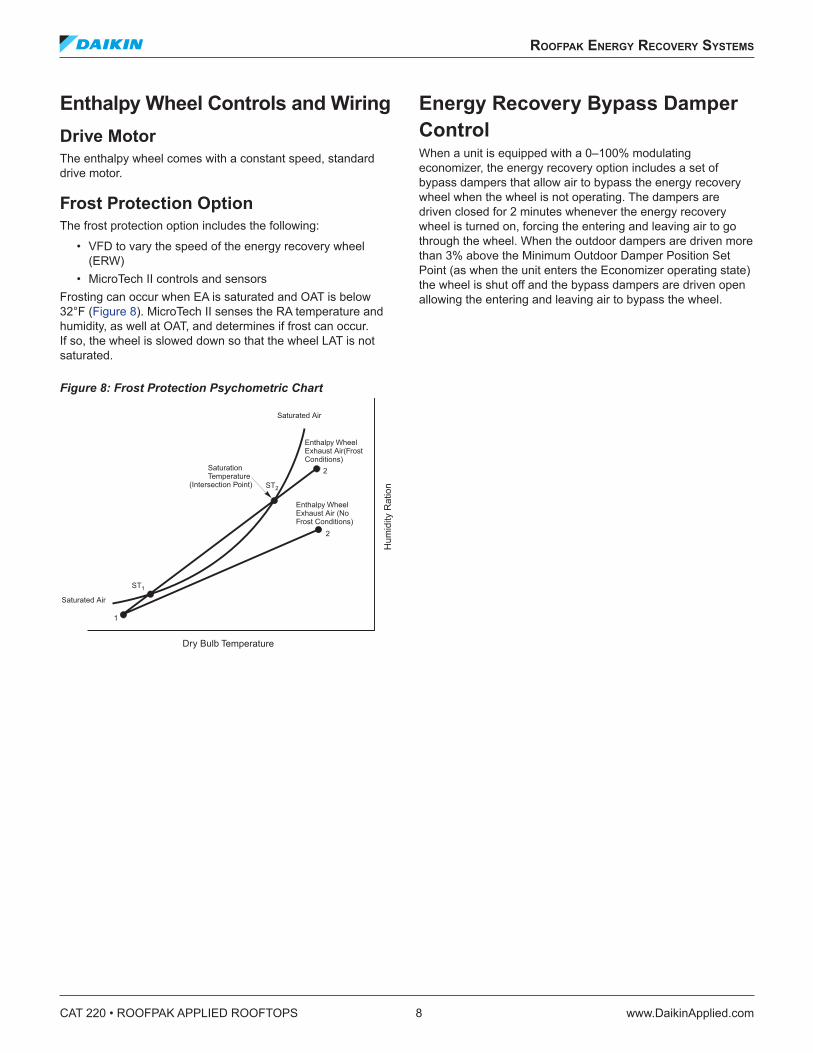
• MicroTech II controls and sensors Frosting can occur when EA is saturated and OAT is below 32°F (Figure 8). MicroTech II senses the RA temperature and humidity, as well at OAT, and determines if frost can occur. If so, the wheel is slowed down so that the wheel LAT is not saturated.
Figure 8: Frost Protection Psychometric Chart
Energy Recovery Bypass Damper ControlWhen a unit is equipped with a 0–100% modulating economizer, the energy recovery option includes a set of bypass dampers that allow air to bypass the energy recovery wheel when the wheel is not operating. The dampers are driven closed for 2 minutes whenever the energy recovery wheel is turned on, forcing the entering and leaving air to go through the wheel. When the outdoor dampers are driven more than 3% above the Minimum Outdoor Damper Position Set Point (as when the unit enters the Economizer operating state) the wheel is shut off and the bypass dampers are driven open allowing the entering and leaving air to bypass the wheel.
Saturated Air
Enthalpy WheelExhaust Air(FrostConditions)
Enthalpy WheelExhaust Air (NoFrost Conditions)
Saturated Air
ST1
1
ST2
2
2SaturationTemperature
Hum
idity
Rat
ion
Dry Bulb Temperature
(Intersection Point)
applICaTIon ConsIderaTIons
www.DaikinApplied.com 9 CAT 220 • ROOFPAK APPLIED ROOFTOPS
applICaTIon ConsIderaTIons
GeneralThe following section contains basic application and installation guidelines that must be considered as part of the detailed analysis of any specific project.
Units are intended for use in normal heating, ventilating and air conditioning applications. Consult your local Daikin sales representative for applications involving operation at high ambient temperatures, high altitudes, non-cataloged voltages and for applications requiring modified or special control sequences. Consult your local Daikin sales representative for job specific unit selections that fall outside of the range of the catalog tables, such as 100% outside air applications.
For proper operation, units should be rigged in accordance with instructions stated in the unit installation manual (IM). Fire dampers, if required, must be installed in the ductwork according to local or state codes. No space is allowed for these dampers in the unit.
Follow factory check, test and start procedures explicitly to achieve satisfactory start-up and operation (see IM 738).
Most rooftop applications take advantage of the significant energy savings provided with economizer operation. When an economizer system is used, mechanical refrigeration is typically not required below an ambient temperature of 50°F. Standard RoofPak refrigeration systems are designed to operate in ambient temperatures down to 45°F. For applications where an economizer system cannot be used, Daikin’s SpeedTrol™ head pressure control system is available on size 045C to 075C units to permit operation down to 0°F. However, if the condenser coils are not properly shielded from the wind, the minimum ambient conditions stated above must be raised.
Unit LocationThe structural engineer must verify that the roof has adequate strength and ability to minimize deflection. Take extreme caution when using a wooden roof structure.
Locate the unit fresh air intakes away from building flue stacks or exhaust ventilators to reduce possible reintroduction of contaminated air to the system. Unit condenser coils should be located to avoid contact with any heated exhaust air.
Allow sufficient space around the unit for maintenance/service clearance as well as to allow for full outside air intake, removal of exhaust air and for full condenser airflow. Refer to Recommended Clearances on page 52 for recommended clearances. Consult your Daikin sales representative if available clearances do not meet minimum recommendations. Where code considerations, such as the NEC, require extended clearances, they take precedence.
In applications utilizing a future cooling unit (RFS), take care in choosing a location of the unit so it will provide proper roof support and service and ventilation clearance necessary for the later addition of a mechanical cooling section (RCS).
Split UnitsUnits may sometimes have to be split into multiple pieces to accommodate shipping limitations or jobsite lifting limitations. Units exceeding 52 feet in length may need to be split for shipping purposes. Units exceeding the rating of an available crane or helicopter may also need to be split for rigging purposes. Unit can be split at the condensing section or split between the supply fan and heat section. Contact your local Daikin sales representative for more details.
Curb InstallationThe roof curb is field assembled and must be installed level (within 1/16 in. per foot side to side). A sub-base has to be constructed by the contractor in applications involving pitched roofs. Gaskets are furnished and must be installed between the unit and curb. For proper installation, follow NRCA guidelines. Typical curb installation is illustrated in Roof Curbs on page 49. In applications requiring post and rail installation, an I-beam securely mounted on multiple posts should support the unit on each side.
Applications in geographic areas that are subjected to seismic or hurricane conditions must meet code requirements for fastening the unit to the curb and the curb to the building structure.
For acoustical considerations, the condensing section is provided with a support rail versus a full perimeter roof curb. When curbs are installed on a built-up roof with metal decking, an inverted 6 in. channel should be provided on both sides of the unit. Acoustical material should be installed over the decking, inside the roof curb. Only the supply and return air ducts should penetrate the acoustical material and decking. Apply appropriate acoustical and vibration design practices during the early stages of design to provide noise compatibility with the intended use of the space. Consult your Daikin sales representative for unit sound power data.
CAT 220 • ROOFPAK APPLIED ROOFTOPS 10 www.DaikinApplied.com
applICaTIon ConsIderaTIons
Acoustical ConsiderationsGood acoustical design is a critical part of any installation and should start at the earliest stages in the design process. Each of the four common sound paths for rooftop equipment must be addressed. These are:
• Radiated sound through the bottom of the unit bottom (air handling section and condensing section) and into the space
• Structure-borne vibration from the unit to the building • Airborne sound through the supply air duct • Airborne sound through the return air duct
Locating rooftop equipment away from sound sensitive areas is critical and the most cost effective means of avoiding sound problems. If possible, rooftop equipment should always be located over less sensitive areas such as corridors, toilet facilities or auxiliary spaces and away from office areas, conference rooms and classrooms.
Some basic guidelines for good acoustical performance are:
• Always provide proper structural support under all areas of the unit
• Always locate the unit’s center of gravity close to a main support to minimize roof deflection. Maintaining a roof deflection under 1/3 in. minimizes vibration-induced noise
• Use a concrete deck or pad when a unit has to be located over an occupied space where good acoustics are essential
• Only the supply and return air ducts should penetrate the acoustical material and decking within the curb perimeter, and the openings must be sealed once the duct is installed
• Don’t overlook the return air path. Never leave a clear “line of sight” into a return or exhaust fan; always include some duct work (acoustically lined tee) at the return inlet
• Place an acoustical material in the area directly beneath the condensing section
• Select acoustic material that does not encourage microbial growth
• Minimize system static pressure losses to reduce fan sound generation
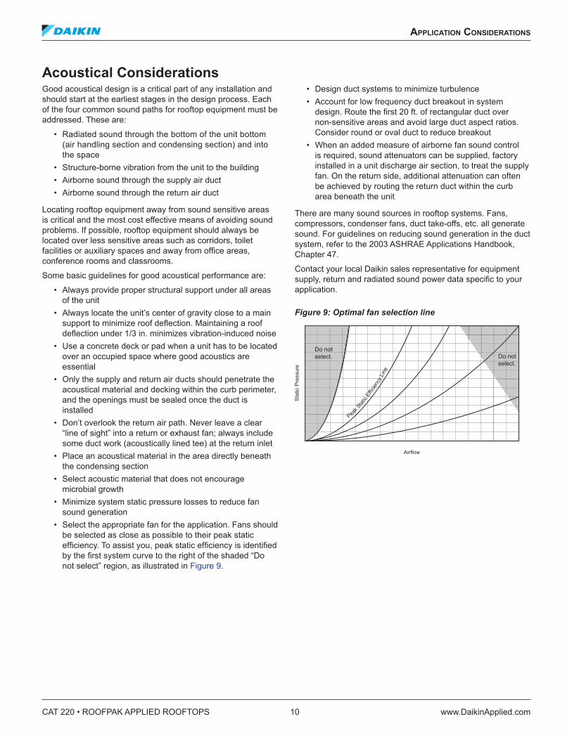
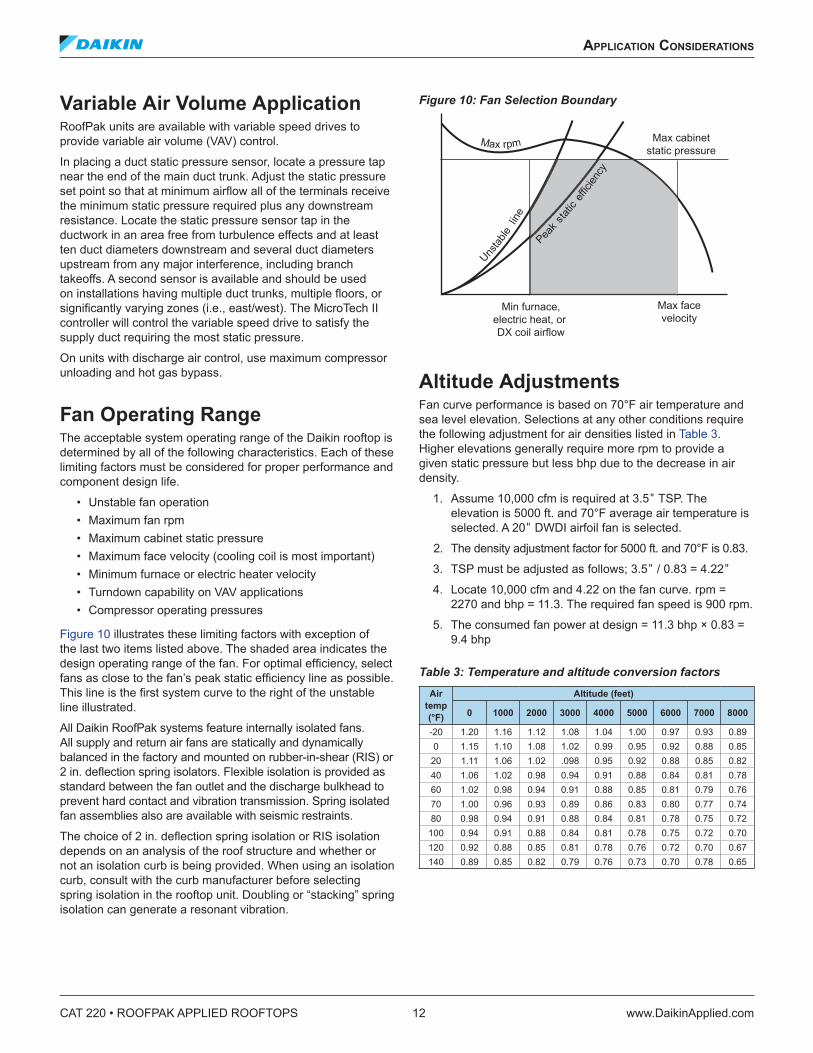
• Select the appropriate fan for the application. Fans should be selected as close as possible to their peak static efficiency. To assist you, peak static efficiency is identified by the first system curve to the right of the shaded “Do not select” region, as illustrated in Figure 9.
• Design duct systems to minimize turbulence • Account for low frequency duct breakout in system
design. Route the first 20 ft. of rectangular duct over non-sensitive areas and avoid large duct aspect ratios. Consider round or oval duct to reduce breakout
• When an added measure of airborne fan sound control is required, sound attenuators can be supplied, factory installed in a unit discharge air section, to treat the supply fan. On the return side, additional attenuation can often be achieved by routing the return duct within the curb area beneath the unit
There are many sound sources in rooftop systems. Fans, compressors, condenser fans, duct take-offs, etc. all generate sound. For guidelines on reducing sound generation in the duct system, refer to the 2003 ASHRAE Applications Handbook, Chapter 47.
Contact your local Daikin sales representative for equipment supply, return and radiated sound power data specific to your application.
Figure 9: Optimal fan selection line
Do not select. Do not
select.
applICaTIon ConsIderaTIons
www.DaikinApplied.com 11 CAT 220 • ROOFPAK APPLIED ROOFTOPS
DuctworkA well-designed duct system is required to allow the rooftop equipment to provide rated performance and to minimize system resistance and sound generation. Duct connections to and from units should allow straight, smooth airflow transitions. Avoid any abrupt change in duct size and sharp turns in the fan discharge. Avoid turns opposed to wheel rotation since they generate air turbulence and result in unwanted sound. If 90° turns are necessary, use turning vanes. Refer to the 2003 ASHRAE Applications Handbook, Chapter 47 for specific guidelines relevant to rooftop equipment.
Return DuctThe return path is the most often overlooked. A section of return duct is required to avoid a “line of sight” to the return air opening and to provide attenuation of return air sound. Install an insulated tee with a maximum duct velocity of 1000 to 1200 feet per minute. Extend the duct 15 feet to provide adequate attenuation.
Supply DuctInsulate supply air ductwork for at least the first 20 feet from the unit. Consider the use of round or oval ductwork, as it significantly reduces low frequency breakout noise near the equipment. If rectangular duct is used, keep the aspect ratio of the duct as low as possible. The large flat surfaces associated with high aspect ratios increase low frequency breakout to the space and can generate noise, such as “oil canning.” The maximum recommended supply duct velocity is 1800 to 2000 feet per minute.
Duct High LimitAll Daikin RoofPak systems with VAV control include an adjustable duct high limit switch as a standard feature. This is of particular importance when fast acting, normally closed boxes are used. The switch is field adjustable and must be set to meet the specific rating of the system ductwork.
Vibration IsolationMake duct attachments to the unit with a flexible connection.
Smoke and Fire Protection Daikin optionally offers factory-installed outdoor air, return air, and exhaust air dampers as well as smoke detectors in the supply and return air opening, complete with wiring and control. These components often are used in the building’s smoke, fume, and fire protection systems. However, due to the wide variation in building design and ambient operating conditions into which our units are applied, we do not represent or warrant that our products are fit and sufficient for smoke, fume, and fire control purposes. The owner and a fully qualified building designer are responsible for meeting all local and NFPA building code requirements with respect to smoke, fume, and fire control. Daikin offers the flexibility to offer these various components and control sequences, as directed by the customer, to help meet code requirements.
FiltersGeneralRoutinely replace filters to minimize filter loading. As filters get dirty, the filter pressure drop increases, causing a decrease in airflow. Depending on fan type, forward curved or airfoil, this airflow change can be significant. The effect of filter loading is the most critical when using 65% and 95% efficient filters.
When making a fan selection, include a pressure drop component in the system total static pressure for filters since they get dirty. Generally, select a value midway between clean and dirty filter ratings. If a minimum airflow is critical, the fan selection should be made using the higher, dirty filter pressure drop value. Following these recommendations should limit airflow fluctuation as the filters load.
Final FiltersThe application of final filters (filters downstream of the fan) places special requirements on unit selection. When final filters are employed, cooling coils must be located in the draw-through position so that the filters will not be in a saturated air stream. Also, final filters applications for a unit with gas heat requires the filters to be rated for 500°F. Instruct maintenance personnel to use properly rated replacement filters.
Wheel CleaningDaikin energy recovery wheels generally only require periodic and easy cleaning as long as outdoor and return air is relatively clean.
• The counter-flow arrangement causes the wheel to be self-cleaning as long as it rotates
• Daikin provides pre-filters on both the outdoor and return air
• Vacuums or soft brushes should be used to periodically clean the wheel so that dirt does not accumulate and promote microbial growth. Be careful not to force dirt into the interior of the wheel
• If periodic cleaning is forgotten and dirt or mildew persists, then water and mild detergents can be used. However, care must be taken to control the water and keep it out of the floor and other exterior cabinet insulation
CAT 220 • ROOFPAK APPLIED ROOFTOPS 12 www.DaikinApplied.com
applICaTIon ConsIderaTIons
Variable Air Volume ApplicationRoofPak units are available with variable speed drives to provide variable air volume (VAV) control.
In placing a duct static pressure sensor, locate a pressure tap near the end of the main duct trunk. Adjust the static pressure set point so that at minimum airflow all of the terminals receive the minimum static pressure required plus any downstream resistance. Locate the static pressure sensor tap in the ductwork in an area free from turbulence effects and at least ten duct diameters downstream and several duct diameters upstream from any major interference, including branch takeoffs. A second sensor is available and should be used on installations having multiple duct trunks, multiple floors, or significantly varying zones (i.e., east/west). The MicroTech II controller will control the variable speed drive to satisfy the supply duct requiring the most static pressure.
On units with discharge air control, use maximum compressor unloading and hot gas bypass.
Fan Operating RangeThe acceptable system operating range of the Daikin rooftop is determined by all of the following characteristics. Each of these limiting factors must be considered for proper performance and component design life.
• Unstable fan operation • Maximum fan rpm • Maximum cabinet static pressure • Maximum face velocity (cooling coil is most important) • Minimum furnace or electric heater velocity • Turndown capability on VAV applications • Compressor operating pressures
Figure 10 illustrates these limiting factors with exception of the last two items listed above. The shaded area indicates the design operating range of the fan. For optimal efficiency, select fans as close to the fan’s peak static efficiency line as possible. This line is the first system curve to the right of the unstable line illustrated.
All Daikin RoofPak systems feature internally isolated fans. All supply and return air fans are statically and dynamically balanced in the factory and mounted on rubber-in-shear (RIS) or 2 in. deflection spring isolators. Flexible isolation is provided as standard between the fan outlet and the discharge bulkhead to prevent hard contact and vibration transmission. Spring isolated fan assemblies also are available with seismic restraints.
The choice of 2 in. deflection spring isolation or RIS isolation depends on an analysis of the roof structure and whether or not an isolation curb is being provided. When using an isolation curb, consult with the curb manufacturer before selecting spring isolation in the rooftop unit. Doubling or “stacking” spring isolation can generate a resonant vibration.
Figure 10: Fan Selection Boundary
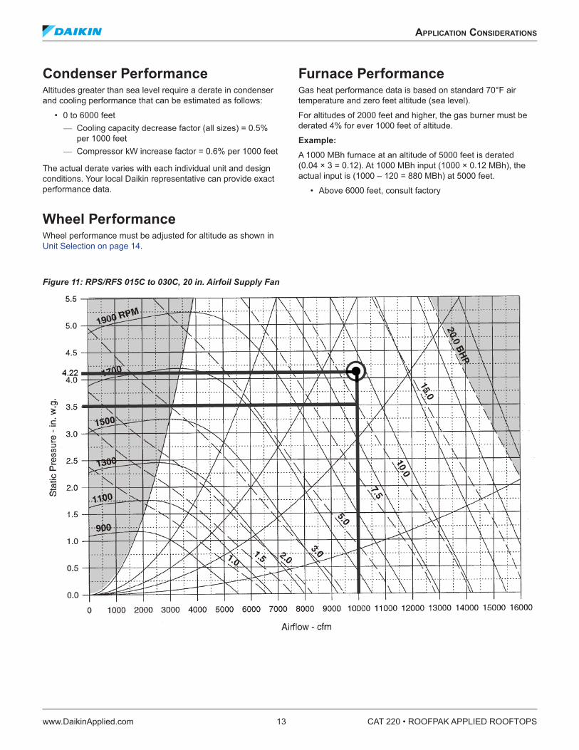
Altitude AdjustmentsFan curve performance is based on 70°F air temperature and sea level elevation. Selections at any other conditions require the following adjustment for air densities listed in Table 3. Higher elevations generally require more rpm to provide a given static pressure but less bhp due to the decrease in air density.
1. Assume 10,000 cfm is required at 3.5" TSP. The elevation is 5000 ft. and 70°F average air temperature is selected. A 20" DWDI airfoil fan is selected.
2. The density adjustment factor for 5000 ft. and 70°F is 0.83.
3. TSP must be adjusted as follows; 3.5" / 0.83 = 4.22"
4. Locate 10,000 cfm and 4.22 on the fan curve. rpm = 2270 and bhp = 11.3. The required fan speed is 900 rpm.
5. The consumed fan power at design = 11.3 bhp × 0.83 = 9.4 bhp
Table 3: Temperature and altitude conversion factors Air
temp (°F)
Altitude (feet)
0 1000 2000 3000 4000 5000 6000 7000 8000
-20 1.20 1.16 1.12 1.08 1.04 1.00 0.97 0.93 0.890 1.15 1.10 1.08 1.02 0.99 0.95 0.92 0.88 0.85
20 1.11 1.06 1.02 .098 0.95 0.92 0.88 0.85 0.8240 1.06 1.02 0.98 0.94 0.91 0.88 0.84 0.81 0.7860 1.02 0.98 0.94 0.91 0.88 0.85 0.81 0.79 0.7670 1.00 0.96 0.93 0.89 0.86 0.83 0.80 0.77 0.7480 0.98 0.94 0.91 0.88 0.84 0.81 0.78 0.75 0.72
100 0.94 0.91 0.88 0.84 0.81 0.78 0.75 0.72 0.70120 0.92 0.88 0.85 0.81 0.78 0.76 0.72 0.70 0.67140 0.89 0.85 0.82 0.79 0.76 0.73 0.70 0.78 0.65
Max facevelocity
Min furnace,electric heat, or DX coil airflow
Max cabinetstatic pressure
l
applICaTIon ConsIderaTIons
www.DaikinApplied.com 13 CAT 220 • ROOFPAK APPLIED ROOFTOPS
Condenser PerformanceAltitudes greater than sea level require a derate in condenser and cooling performance that can be estimated as follows:
• 0 to 6000 feet — Cooling capacity decrease factor (all sizes) = 0.5% per 1000 feet
— Compressor kW increase factor = 0.6% per 1000 feet
The actual derate varies with each individual unit and design conditions. Your local Daikin representative can provide exact performance data.
Wheel PerformanceWheel performance must be adjusted for altitude as shown in Unit Selection on page 14.
Furnace Performance Gas heat performance data is based on standard 70°F air temperature and zero feet altitude (sea level).
For altitudes of 2000 feet and higher, the gas burner must be derated 4% for ever 1000 feet of altitude.
Example: A 1000 MBh furnace at an altitude of 5000 feet is derated (0.04 × 3 = 0.12). At 1000 MBh input (1000 × 0.12 MBh), the actual input is (1000 – 120 = 880 MBh) at 5000 feet.
• Above 6000 feet, consult factory
Figure 11: RPS/RFS 015C to 030C, 20 in. Airfoil Supply Fan
CAT 220 • ROOFPAK APPLIED ROOFTOPS 14 www.DaikinApplied.com
unIT seleCTIon
unIT seleCTIon
Achieving the optimal performance of a rooftop system requires both accurate system design and proper equipment selection. Factors that control the unit selection include applicable codes, ventilation and air filtration requirements, heating and cooling loads, acceptable temperature differentials, and installation limitations. Daikin RoofPak units offer a wide selection of component options providing the capability to meet diverse application requirements.
The Daikin Tools™ software selection program allows your local Daikin sales representative to provide you with fast, accurate and complete selection of Daikin RoofPak units. You also can select your unit through reference to physical, performance, dimensional, and unit weight data included in this catalog. Due to the variety of cooling coil options available, only a sample of cooling capacity data is presented in the catalog. To properly select unit equipment:
1. Select unit size and cooling coil
2. Select heating coils and equipment
3. Select fans and motors
Below are examples that illustrate the equations and catalog references used in the unit selection process.
Selection Example: Constant volume system with DX cooling and natural gas heat. System Design:
Supply air volume . . . . . . . . . . . . . . . . . . . . . . . . . . . . . . . . . . . . . . 20,000 cfm Return air volume. . . . . . . . . . . . . . . . . . . . . . . . . . . . . . . . . . . . . . . 20,000 cfm Minimum outside air volume . . . . . . . . . . . . . . . . . . . . . . . . . . . . . . . . 7000 cfm Maximum face velocity. . . . . . . . . . . . . . . . . . . . . . . . . . . . . . . . . . . . . . 550 fpm Supply fan external SP . . . . . . . . . . . . . . . . . . . . . . . . . . . . . . . . . .2.00 in. w.g. Return fan external SP. . . . . . . . . . . . . . . . . . . . . . . . . . . . . . . . . . .1.00 in. w.g. Altitude. . . . . . . . . . . . . . . . . . . . . . . . . . . . . . . . . . . . . . . . . . . . . . . . . Sea level Economizer with return air fan Energy recovery wheel 30% throw-away filters 460V/60Hz/3Ph Fully modulating heat
Summer Design: (RAT) Return air temperature . . . . . . . . . . . . . . . . . . . . . . . . . . . . . . 75°F/62°F (OAT) Outdoor air temperature . . . . . . . . . . . . . . . . . . . . . . . . . . . . . 95°F/75°F (WLAT) Wheel leaving air temperature . . . . . . . . . . . . . . . . . . . . . .80°F/65.5°F DX coil capacity . . . . . . . . . . . . . . . . . . . . . . . . . . . . . . . . . . . . . . . . . . .700MBh
Winter Design: Return air temperature. . . . . . . . . . . . . . . . . . . . . . . . . . . . . . . . . . . . . . 72°F dB Outdoor air temperature. . . . . . . . . . . . . . . . . . . . . . . . . . . . . . . . . . . . . 33°F dB Wheel leaving air temperature. . . . . . . . . . . . . . . . . . . . . . . . . . . . . . . . 61°F dB Gas heat MBh output 380 . . . . . . . . . . . . . . . . . . . . . . . . . . . . . . . . . . . . . .MBh
Maximum Motor HP: Supply fan . . . . . . . . . . . . . . . . . . . . . . . . . . . . . . . . . . . . . . . . . . . . . . . . . 20 hp Return/exhaust fan. . . . . . . . . . . . . . . . . . . . . . . . . . . . . . . . . . . . . . . . . . . 15 hp
Selecting Unit Size to Satisfy Summer DesignUnit size is based on coil face area and cooling capacity requirements. Supply air capacity and maximum face velocity constraints should serve as a guide for selecting coil dimensions and cabinet size. Many model sizes are available with a standard and a high airflow coil selection. This flexibility prevents the need to increase cabinet size to accommodate high airflow per ton applications.
Based on the given data, the appropriate coil face area may be determined as follows:
Minimum face area = supply air volume/maximum face velocity
= 20,000 cfm/550 fpm
= 36.4 square feet
Referring to Physical Data on page 18, the 39.5 square foot, small face area coil of the RPS 045C to 75C units satisfies the required face velocity.
unIT seleCTIon
www.DaikinApplied.com 15 CAT 220 • ROOFPAK APPLIED ROOFTOPS
Wheel Cooling Capacity
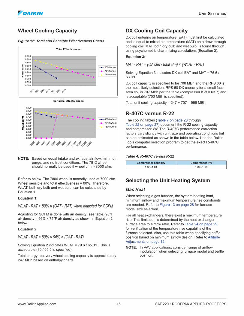
Figure 12: Total and Sensible Effectiveness Charts
NOTE: Based on equal intake and exhaust air flow, minimum purge, and no frost conditions. The 7812 wheel should normally be used if wheel cfm > 8000 cfm.
Refer to below. The 7806 wheel is normally used at 7000 cfm. Wheel sensible and total effectiveness = 80%. Therefore, WLAT, both dry bulb and wet bulb, can be calculated by Equation 1.
Equation 1:
WLAT - RAT + 80% × (OAT - RAT) when adjusted for SCFM
Adjusting for SCFM is done with air density (see table) 95°F air density = 96% x 75°F air density as shown in Equation 2 below.
Equation 2:
WLAT - RAT = 80% × 96% × (OAT - RAT)
Solving Equation 2 indicates WLAT = 79.6 / 65.0°F. This is acceptable (80 / 65.5 is specified).
Total energy recovery wheel cooling capacity is approximately 247 MBh based on enthalpy charts.
DX Cooling Coil CapacityDX coil entering air temperature (EAT) must first be calculated and is equal to mixed air temperature (MAT) on a draw-through cooling coil. MAT, both dry bulb and wet bulb, is found through using psychometric chart mixing calculations (Equation 3).
Equation 3:
MAT - RAT = (OA cfm / total cfm) × (WLAT - RAT)
Solving Equation 3 indicates DX coil EAT and MAT = 76.6 / 63.0°F.
DX coil capacity is specified to be 700 MBh and the RPS 60 is the most likely selection. RPS 60 DX capacity for a small face area coil is 707 MBh per the table (compressor KW = 63.7) and is acceptable (700 MBh is specified).
Total unit cooling capacity = 247 + 707 = 956 MBh.
R-407C versus R-22The cooling tables (Table 7 on page 20 through Table 22 on page 27) document the R-22 cooling capacity and compressor kW. The R-407C performance correction factors vary slightly with unit size and operating conditions but can be estimated as shown in the table below. Use the Daikin Tools computer selection program to get the exact R-407C performance.
Table 4: R-407C versus R-22 Compressor capacity Compressor kW
1.00–1.01 1.07–1.10
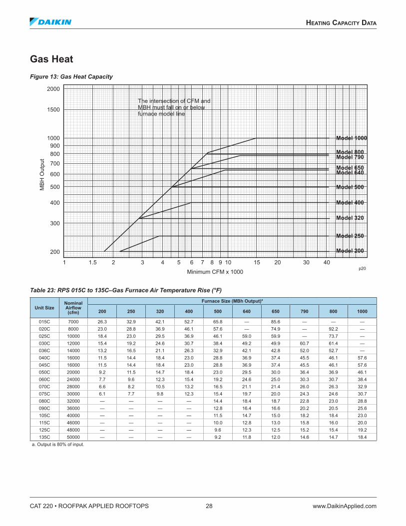
Selecting the Unit Heating SystemGas HeatWhen selecting a gas furnace, the system heating load, minimum airflow and maximum temperature rise constraints are needed. Refer to Figure 13 on page 28 for furnace model size selection.
For all heat exchangers, there exist a maximum temperature rise. This limitation is determined by the heat exchanger surface area to airflow ratio. Refer to Table 24 on page 29 for verification of the temperature rise capability of the furnace selected. Also, use this table when specifying baffle position based on minimum airflow design. Refer to Altitude Adjustments on page 12. NOTE: In VAV applications, consider range of airflow
modulation when selecting furnace model and baffle position.
Total Effectiveness
0.5000.5500.6000.6500.7000.7500.8000.8500.9000.950
3000
4000
5000
6000
7000
8000
9000
Whe
el S
CFM 6004 wheel
7812 wheel
7806 wheel
Sensible Effectiveness
0.0000.1000.2000.3000.4000.5000.6000.7000.8000.9001.000
3000
4000
5000
6000
7000
8000
9000
10,00
0
11,00
0
12,00
0
13,00
0
14,00
0
Whe
el S
CFM 6004 wheel
7812 wheel
7806 wheel
CAT 220 • ROOFPAK APPLIED ROOFTOPS 16 www.DaikinApplied.com
unIT seleCTIon
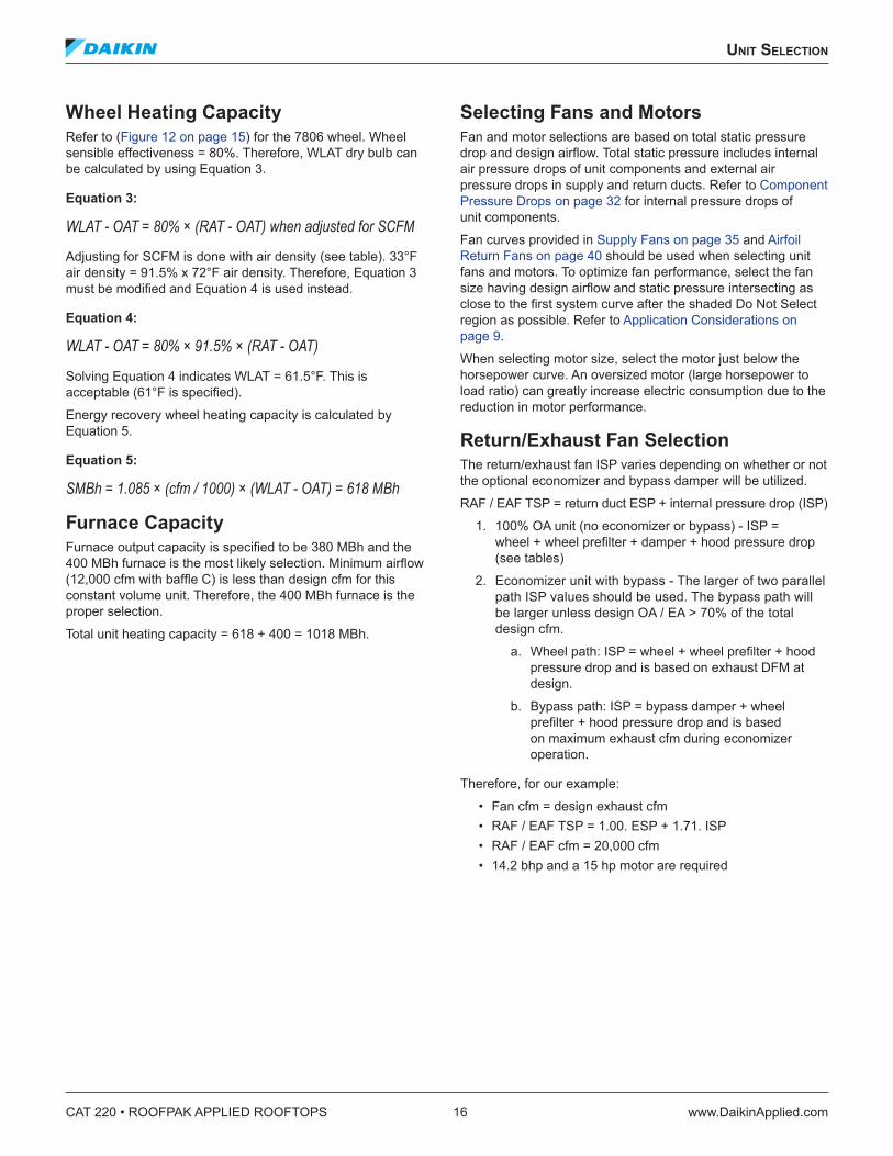
Wheel Heating Capacity Refer to (Figure 12 on page 15) for the 7806 wheel. Wheel sensible effectiveness = 80%. Therefore, WLAT dry bulb can be calculated by using Equation 3.
Equation 3:
WLAT - OAT = 80% × (RAT - OAT) when adjusted for SCFM
Adjusting for SCFM is done with air density (see table). 33°F air density = 91.5% x 72°F air density. Therefore, Equation 3 must be modified and Equation 4 is used instead.
Equation 4:
WLAT - OAT = 80% × 91.5% × (RAT - OAT)
Solving Equation 4 indicates WLAT = 61.5°F. This is acceptable (61°F is specified).
Energy recovery wheel heating capacity is calculated by Equation 5.
Equation 5:
SMBh = 1.085 × (cfm / 1000) × (WLAT - OAT) = 618 MBh
Furnace CapacityFurnace output capacity is specified to be 380 MBh and the 400 MBh furnace is the most likely selection. Minimum airflow (12,000 cfm with baffle C) is less than design cfm for this constant volume unit. Therefore, the 400 MBh furnace is the proper selection.
Total unit heating capacity = 618 + 400 = 1018 MBh.
Selecting Fans and MotorsFan and motor selections are based on total static pressure drop and design airflow. Total static pressure includes internal air pressure drops of unit components and external air pressure drops in supply and return ducts. Refer to Component Pressure Drops on page 32 for internal pressure drops of unit components.
Fan curves provided in Supply Fans on page 35 and Airfoil Return Fans on page 40 should be used when selecting unit fans and motors. To optimize fan performance, select the fan size having design airflow and static pressure intersecting as close to the first system curve after the shaded Do Not Select region as possible. Refer to Application Considerations on page 9.
When selecting motor size, select the motor just below the horsepower curve. An oversized motor (large horsepower to load ratio) can greatly increase electric consumption due to the reduction in motor performance.
Return/Exhaust Fan SelectionThe return/exhaust fan ISP varies depending on whether or not the optional economizer and bypass damper will be utilized.
RAF / EAF TSP = return duct ESP + internal pressure drop (ISP)
1. 100% OA unit (no economizer or bypass) - ISP = wheel + wheel prefilter + damper + hood pressure drop (see tables)
2. Economizer unit with bypass - The larger of two parallel path ISP values should be used. The bypass path will be larger unless design OA / EA > 70% of the total design cfm.
a. Wheel path: ISP = wheel + wheel prefilter + hood pressure drop and is based on exhaust DFM at design.
b. Bypass path: ISP = bypass damper + wheel prefilter + hood pressure drop and is based on maximum exhaust cfm during economizer operation.
Therefore, for our example:
• Fan cfm = design exhaust cfm • RAF / EAF TSP = 1.00. ESP + 1.71. ISP • RAF / EAF cfm = 20,000 cfm • 14.2 bhp and a 15 hp motor are required
unIT seleCTIon
www.DaikinApplied.com 17 CAT 220 • ROOFPAK APPLIED ROOFTOPS
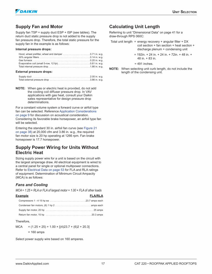
Supply Fan and MotorSupply fan TSP = supply duct ESP + ISP (see tables). The return duct static pressure drop is not added to the supply fan pressure drop. Therefore, the total static pressure for the supply fan in the example is as follows:
Internal pressure drops: Hood, wheel prefilter, wheel and damper . . . . . . . . . . . . . . . . . . . .0.71 in. w.g. 30% angular filters . . . . . . . . . . . . . . . . . . . . . . . . . . . . . . . . . . . . . .0.14 in. w.g. Gas furnace . . . . . . . . . . . . . . . . . . . . . . . . . . . . . . . . . . . . . . . . . . .0.20 in. w.g. Evaporative coil (small 5-row, 12 fpi) . . . . . . . . . . . . . . . . . . . . . . . .0.81 in. w.g. Total internal pressure drop . . . . . . . . . . . . . . . . . . . . . . . . . . . . . . .1.86 in. w.g.
External pressure drops: Supply duct . . . . . . . . . . . . . . . . . . . . . . . . . . . . . . . . . . . . . . . . . . .2.00 in. w.g. Total external pressure drop . . . . . . . . . . . . . . . . . . . . . . . . . . . . . .3.86 in. w.g.
NOTE: When gas or electric heat is provided, do not add the cooling coil diffuser pressure drop. In VAV applications with gas heat, consult your Daikin sales representative for design pressure drop determinations.
For a constant volume system a forward curve or airfoil type fan can be selected. Reference Application Considerations on page 9 for discussion on acoustical consideration. Considering its favorable brake horsepower, an airfoil type fan will be selected.
Entering the standard 30 in. airfoil fan curve (see Figure 21 on page 38) at 20,000 cfm and 3.86 in. w.g., the required fan motor size is 20 hp operating at 1266 rpm. Fan brake horsepower is 17.7 horsepower.
Supply Power Wiring for Units Without Electric Heat Sizing supply power wire for a unit is based on the circuit with the largest amperage draw. All electrical equipment is wired to a central panel for single or optional multipower connections. Refer to Electrical Data on page 53 for FLA and RLA ratings of equipment. Determination of Minimum Circuit Ampacity (MCA) is as follows:
Fans and Cooling MCA = 1.25 × RLA or FLA of largest motor + 1.00 × FLA of other loadsExample FLA/RLA
Compressors 1 - 4 15 hp ea . . . . . . . . . . . . . . . . . . . . . . . . . . .23.7 amps each
Condenser fan motors, (6) 1 hp 2 . . . . . . . . . . . . . . . . . . . . . . . . . . .amps each
Supply fan motor, 20 hp . . . . . . . . . . . . . . . . . . . . . . . . . . . . . . . . . . . 25 amps
Return fan motor, 15 hp . . . . . . . . . . . . . . . . . . . . . . . . . . . . . . . . . . 20.3 amps
Therefore,
MCA = (1.25 × 25) + 1.00 × [(4)23.7 + (6)2 + 20.3]
= 160 amps
Select power supply wire based on 160 amperes.
Calculating Unit LengthReferring to unit “Dimensional Data” on page 41 for a draw-through RPS 060C:
Total unit length = energy recovery + angular filter + DX coil section + fan section + heat section + discharge plenum + condensing unit
= 192in. + 24 in. + 24 in. + 72in. + 48 in. + 48 in. + 83 in.
= 491 inches. NOTE: When selecting unit curb length, do not include the
length of the condensing unit.
CAT 220 • ROOFPAK APPLIED ROOFTOPS 18 www.DaikinApplied.com
physICal daTa
physICal daTa
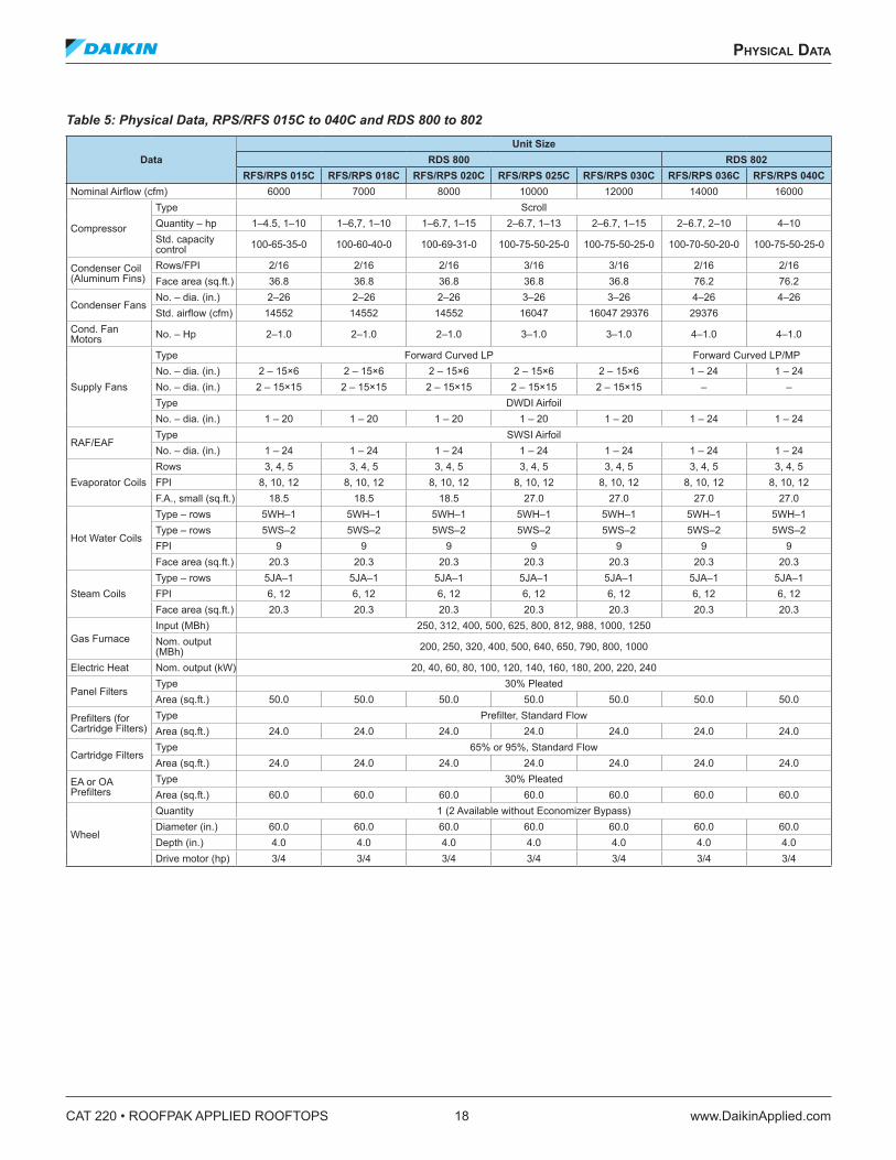
Table 5: Physical Data, RPS/RFS 015C to 040C and RDS 800 to 802
DataUnit Size
RDS 800 RDS 802RFS/RPS 015C RFS/RPS 018C RFS/RPS 020C RFS/RPS 025C RFS/RPS 030C RFS/RPS 036C RFS/RPS 040C
Nominal Airflow (cfm) 6000 7000 8000 10000 12000 14000 16000
Compressor
Type ScrollQuantity – hp 1–4.5, 1–10 1–6,7, 1–10 1–6.7, 1–15 2–6.7, 1–13 2–6.7, 1–15 2–6.7, 2–10 4–10Std. capacity control 100-65-35-0 100-60-40-0 100-69-31-0 100-75-50-25-0 100-75-50-25-0 100-70-50-20-0 100-75-50-25-0
Condenser Coil (Aluminum Fins)
Rows/FPI 2/16 2/16 2/16 3/16 3/16 2/16 2/16Face area (sq.ft.) 36.8 36.8 36.8 36.8 36.8 76.2 76.2
Condenser FansNo. – dia. (in.) 2–26 2–26 2–26 3–26 3–26 4–26 4–26Std. airflow (cfm) 14552 14552 14552 16047 16047 29376 29376
Cond. Fan Motors No. – Hp 2–1.0 2–1.0 2–1.0 3–1.0 3–1.0 4–1.0 4–1.0
Supply Fans
Type Forward Curved LP Forward Curved LP/MPNo. – dia. (in.) 2 – 15×6 2 – 15×6 2 – 15×6 2 – 15×6 2 – 15×6 1 – 24 1 – 24No. – dia. (in.) 2 – 15×15 2 – 15×15 2 – 15×15 2 – 15×15 2 – 15×15 – –Type DWDI AirfoilNo. – dia. (in.) 1 – 20 1 – 20 1 – 20 1 – 20 1 – 20 1 – 24 1 – 24
RAF/EAFType SWSI AirfoilNo. – dia. (in.) 1 – 24 1 – 24 1 – 24 1 – 24 1 – 24 1 – 24 1 – 24
Evaporator CoilsRows 3, 4, 5 3, 4, 5 3, 4, 5 3, 4, 5 3, 4, 5 3, 4, 5 3, 4, 5FPI 8, 10, 12 8, 10, 12 8, 10, 12 8, 10, 12 8, 10, 12 8, 10, 12 8, 10, 12F.A., small (sq.ft.) 18.5 18.5 18.5 27.0 27.0 27.0 27.0
Hot Water Coils
Type – rows 5WH–1 5WH–1 5WH–1 5WH–1 5WH–1 5WH–1 5WH–1Type – rows 5WS–2 5WS–2 5WS–2 5WS–2 5WS–2 5WS–2 5WS–2FPI 9 9 9 9 9 9 9Face area (sq.ft.) 20.3 20.3 20.3 20.3 20.3 20.3 20.3
Steam CoilsType – rows 5JA–1 5JA–1 5JA–1 5JA–1 5JA–1 5JA–1 5JA–1FPI 6, 12 6, 12 6, 12 6, 12 6, 12 6, 12 6, 12Face area (sq.ft.) 20.3 20.3 20.3 20.3 20.3 20.3 20.3
Gas FurnaceInput (MBh) 250, 312, 400, 500, 625, 800, 812, 988, 1000, 1250Nom. output (MBh) 200, 250, 320, 400, 500, 640, 650, 790, 800, 1000
Electric Heat Nom. output (kW) 20, 40, 60, 80, 100, 120, 140, 160, 180, 200, 220, 240
Panel FiltersType 30% PleatedArea (sq.ft.) 50.0 50.0 50.0 50.0 50.0 50.0 50.0
Prefilters (for Cartridge Filters)
Type Prefilter, Standard FlowArea (sq.ft.) 24.0 24.0 24.0 24.0 24.0 24.0 24.0
Cartridge FiltersType 65% or 95%, Standard FlowArea (sq.ft.) 24.0 24.0 24.0 24.0 24.0 24.0 24.0
EA or OA Prefilters
Type 30% PleatedArea (sq.ft.) 60.0 60.0 60.0 60.0 60.0 60.0 60.0
Wheel
Quantity 1 (2 Available without Economizer Bypass)Diameter (in.) 60.0 60.0 60.0 60.0 60.0 60.0 60.0Depth (in.) 4.0 4.0 4.0 4.0 4.0 4.0 4.0Drive motor (hp) 3/4 3/4 3/4 3/4 3/4 3/4 3/4
physICal daTa
www.DaikinApplied.com 19 CAT 220 • ROOFPAK APPLIED ROOFTOPS
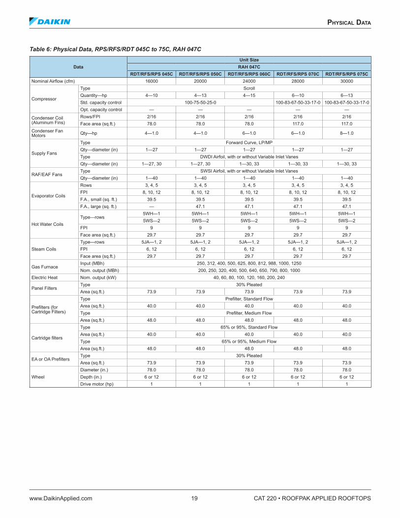
Table 6: Physical Data, RPS/RFS/RDT 045C to 75C, RAH 047C
DataUnit Size
RAH 047CRDT/RFS/RPS 045C RDT/RFS/RPS 050C RDT/RFS/RPS 060C RDT/RFS/RPS 070C RDT/RFS/RPS 075C
Nominal Airflow (cfm) 16000 20000 24000 28000 30000
Compressor
Type ScrollQuantity—hp 4—10 4—13 4—15 6—10 6—13Std. capacity control 100-75-50-25-0 100-83-67-50-33-17-0 100-83-67-50-33-17-0Opt. capacity control — — — — —
Condenser Coil (Aluminum Fins)
Rows/FPI 2/16 2/16 2/16 2/16 2/16Face area (sq.ft.) 78.0 78.0 78.0 117.0 117.0
Condenser Fan Motors Qty—hp 4—1.0 4—1.0 6—1.0 6—1.0 8—1.0
Supply Fans
Type Forward Curve, LP/MPQty—diameter (in) 1—27 1—27 1—27 1—27 1—27Type DWDI Airfoil, with or without Variable Inlet VanesQty—diameter (in) 1—27, 30 1—27, 30 1—30, 33 1—30, 33 1—30, 33
RAF/EAF FansType SWSI Airfoil, with or without Variable Inlet VanesQty—diameter (in) 1—40 1—40 1—40 1—40 1—40
Evaporator Coils
Rows 3, 4, 5 3, 4, 5 3, 4, 5 3, 4, 5 3, 4, 5FPI 8, 10, 12 8, 10, 12 8, 10, 12 8, 10, 12 8, 10, 12F.A., small (sq. ft.) 39.5 39.5 39.5 39.5 39.5F.A., large (sq. ft.) — 47.1 47.1 47.1 47.1
Hot Water CoilsType—rows
5WH—1 5WH—1 5WH—1 5WH—1 5WH—15WS—2 5WS—2 5WS—2 5WS—2 5WS—2
FPI 9 9 9 9 9Face area (sq.ft.) 29.7 29.7 29.7 29.7 29.7
Steam CoilsType—rows 5JA—1, 2 5JA—1, 2 5JA—1, 2 5JA—1, 2 5JA—1, 2FPI 6, 12 6, 12 6, 12 6, 12 6, 12Face area (sq.ft.) 29.7 29.7 29.7 29.7 29.7
Gas FurnaceInput (MBh) 250, 312, 400, 500, 625, 800, 812, 988, 1000, 1250Nom. output (MBh) 200, 250, 320, 400, 500, 640, 650, 790, 800, 1000
Electric Heat Nom. output (kW) 40, 60, 80, 100, 120, 160, 200, 240
Panel FiltersType 30% PleatedArea (sq.ft.) 73.9 73.9 73.9 73.9 73.9
Prefilters (for Cartridge Filters)
Type Prefilter, Standard FlowArea (sq.ft.) 40.0 40.0 40.0 40.0 40.0Type Prefilter, Medium FlowArea (sq.ft.) 48.0 48.0 48.0 48.0 48.0
Cartridge filters
Type 65% or 95%, Standard FlowArea (sq.ft.) 40.0 40.0 40.0 40.0 40.0Type 65% or 95%, Medium FlowArea (sq.ft.) 48.0 48.0 48.0 48.0 48.0
EA or OA PrefiltersType 30% PleatedArea (sq.ft.) 73.9 73.9 73.9 73.9 73.9
WheelDiameter (in.) 78.0 78.0 78.0 78.0 78.0Depth (in.) 6 or 12 6 or 12 6 or 12 6 or 12 6 or 12Drive motor (hp) 1 1 1 1 1
CAT 220 • ROOFPAK APPLIED ROOFTOPS 20 www.DaikinApplied.com
CoolIng CapaCITy daTa
CoolIng CapaCITy daTa
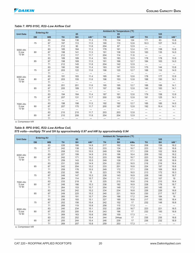
Table 7: RPS 015C, R22–Low Airflow Coil
Unit Data Entering Air Ambient Air Temperature (°F)85 95 105
DB WB TH SH kW a TH SH kWa TH SH kW a
5000 cfm 5 row 12 fpi
7563 184 136 11.3 178 134 124 171 63 13.867 197 113 11.5 190 110 12.6 18.3 107 14.071 212 90 11.8 204 87 12.9 — — —
8063 185 164 11.3 178 161 12.4 171 158 13.867 198 141 11.5 191 138 12.6 183 135 14.071 212 117 11.7 204 114 11.9 — — —
8563 189 189 11.4 183 183 12.5 178 178 13.967 198 169 11.5 191 166 12.7 184 163 14.071 212 145 11.8 204 142 12.9 — — —
6000 cfm 5 row 12 fpi
7563 190 150 11.4 183 147 12.5 175 144 13.867 203 122 11.6 196 120 12.7 188 116 14.071 — — — — — — — — —
8063 191 183 11.4 185 181 12.6 178 177 13.967 203 155 11.6 196 153 12.8 188 150 14.171 — — — — — — — — —
8563 201 201 11.6 195 195 12.7 188 188 14.167 205 189 11.7 197 186 12.8 140 183 14.171 — — — — — — — — —
7000 cfm 5 row 12 fpi
7563 194 164 11.4 187 161 12.6 179 158 13.967 207 131 11.7 200 128 12.8 191 125 14.171 — — — — — — — — —
8063 198 198 11.5 192 192 12.7 185 185 14.067 207 170 11.7 200 167 12.8 192 16.4 14.171 — — — — — — — — —
8563 210 210 11.7 203 203 12.8 — — —67 210 208 11.8 204 204 12.9 — — —71 — — — — — — — — —
a. Compressor kW
Table 8: RPS 018C, R22–Low Airflow Coil, 575 volts—multiply TH and SH by approximately 0.97 and kW by approximately 0.94
Unit Data Entering Air Ambient Air Temperature (°F)85 95 105
DB WB TH SH kW a TH SH kWa TH SH kW a
6000 cfm 5 row 12 fpi
7563 226 166 14.8 217 162 16.4 208 158 18.267 242 138 15.2 233 134 16.7 223 130 18.671 259 110 15.5 249 106 17.1 239 102 18.9
8063 227 199 14.9 218 196 16.4 209 192 18.267 242 171 15.2 233 168 16.7 223 164 18.671 259 143 15.5 249 139 17.1 239 135 18.9
8563 231 228 14.9 224 222 16.5 216 216 18.467 242 204 15.2 233 201 16.8 224 197 18.671 259 176 15.5 249 172 17.1 239 169 18.9
7000 cfm 5 row 12 fpi
7563 232 180 15 223 176 16.5 213 172 18.367 248 147 15.3 238 143 16.9 228 140 18.771 264 114 15.7 254 111 17.2 243 107 19
8063 233 218 15 225 215 16.6 216 210 18.467 248 186 15.3 238 182 16.9 228 178 18.771 264 153 15.7 254 149 17.2 243 145 19
8563 242 242 15.2 234 234 16.8 226 226 18.667 249 225 15.3 240 221 16.9 230 217 18.771 265 191 15.7 254 188 17.2 244 184 19
8000 cfm 5 row 12 fpi
7563 236 193 15.1 227 189 16.6 217 185 18.467 252 156 15.4 242 152 17 232 148 18.871 269 119 15.8 258 115 17.3 — — —
8063 240 234 15.1 232 228 16.7 223 221 18.567 252 200 15.4 243 196 17 232 193 18.871 269 163 15.8 258 159 17.3 — — —
8563 252 252 15.4 244 244aa 17 235 235 18.867 255 244 15.4 246 239 17 236 232 18.971 269 207 15.8 259 203 17.3 — — —
a. Compressor kW
CoolIng CapaCITy daTa
www.DaikinApplied.com 21 CAT 220 • ROOFPAK APPLIED ROOFTOPS
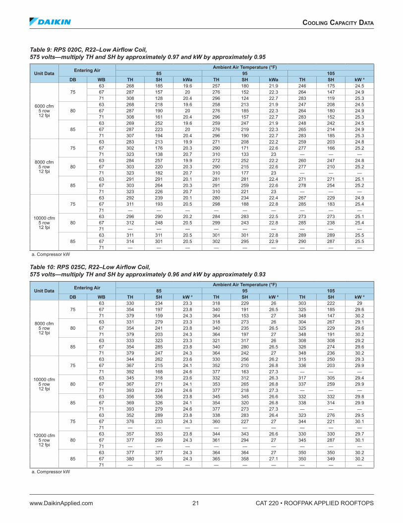
Table 9: RPS 020C, R22–Low Airflow Coil, 575 volts—multiply TH and SH by approximately 0.97 and kW by approximately 0.95
Unit Data Entering Air Ambient Air Temperature (°F)85 95 105
DB WB TH SH kWa TH SH kWa TH SH kW a
6000 cfm 5 row 12 fpi
7563 268 185 19.6 257 180 21.9 246 175 24.567 287 157 20 276 152 22.3 264 147 24.971 308 128 20.4 296 124 22.7 283 119 25.3
8063 268 218 19.6 258 213 21.9 247 208 24.567 287 190 20 276 185 22.3 264 180 24.971 308 161 20.4 296 157 22.7 283 152 25.3
8563 269 252 19.6 259 247 21.9 248 242 24.567 287 223 20 276 219 22.3 265 214 24.971 307 194 20.4 296 190 22.7 283 185 25.3
8000 cfm 5 row 12 fpi
7563 283 213 19.9 271 208 22.2 259 203 24.867 302 176 20.3 290 171 22.6 277 166 25.271 323 138 20.7 310 133 23 — — —
8063 284 257 19.9 272 252 22.2 260 247 24.867 303 220 20.3 290 215 22.6 277 210 25.271 323 182 20.7 310 177 23 — — —
8563 291 291 20.1 281 281 22.4 271 271 25.167 303 264 20.3 291 259 22.6 278 254 25.271 323 226 20.7 310 221 23 — — —
10000 cfm 5 row 12 fpi
7563 292 239 20.1 280 234 22.4 267 229 24.967 311 193 20.5 298 188 22.8 285 183 25.471 — — — — — — — — —
8063 296 290 20.2 284 283 22.5 273 273 25.167 312 248 20.5 299 243 22.8 285 238 25.471 — — — — — — — — —
8563 311 311 20.5 301 301 22.8 289 289 25.567 314 301 20.5 302 295 22.9 290 287 25.571 — — — — — — — — —
a. Compressor kW
Table 10: RPS 025C, R22–Low Airflow Coil, 575 volts—multiply TH and SH by approximately 0.96 and kW by approximately 0.93
Unit Data Entering Air Ambient Air Temperature (°F) 85 95 105
DB WB TH SH kW a TH SH kW a TH SH kW a
8000 cfm 5 row 12 fpi
7563 330 234 23.3 318 229 26 303 222 2967 354 197 23.8 340 191 26.5 325 185 29.671 379 159 24.3 364 153 27 348 147 30.2
8063 331 279 23.3 318 273 26 304 267 29.167 354 241 23.8 340 235 26.5 325 229 29.671 379 203 24.3 364 197 27 348 191 30.2
8563 333 323 23.3 321 317 26 308 308 29.267 354 285 23.8 340 280 26.5 326 274 29.671 379 247 24.3 364 242 27 348 236 30.2
10000 cfm 5 row 12 fpi
7563 344 262 23.6 330 256 26.2 315 250 29.367 367 215 24.1 352 210 26.8 336 203 29.971 392 168 24.6 377 163 27.3 — — —
8063 345 318 23.6 332 312 26.3 317 305 29.467 367 271 24.1 353 265 26.8 337 259 29.971 393 224 24.6 377 218 27.3 — — —
8563 356 356 23.8 345 345 26.6 332 332 29.867 369 326 24.1 354 320 26.8 338 314 29.971 393 279 24.6 377 273 27.3 — — —
12000 cfm 5 row 12 fpi
7563 352 289 23.8 338 283 26.4 323 276 29.567 376 233 24.3 360 227 27 344 221 30.171 — — — — — — — — —
8063 357 353 23.8 344 343 26.6 330 330 29.767 377 299 24.3 361 294 27 345 287 30.171 — — — — — — — — —
8563 377 377 24.3 364 364 27 350 350 30.267 380 365 24.3 365 358 27.1 350 349 30.271 — — — — — — — — —
a. Compressor kW
CAT 220 • ROOFPAK APPLIED ROOFTOPS 22 www.DaikinApplied.com
CoolIng CapaCITy daTa
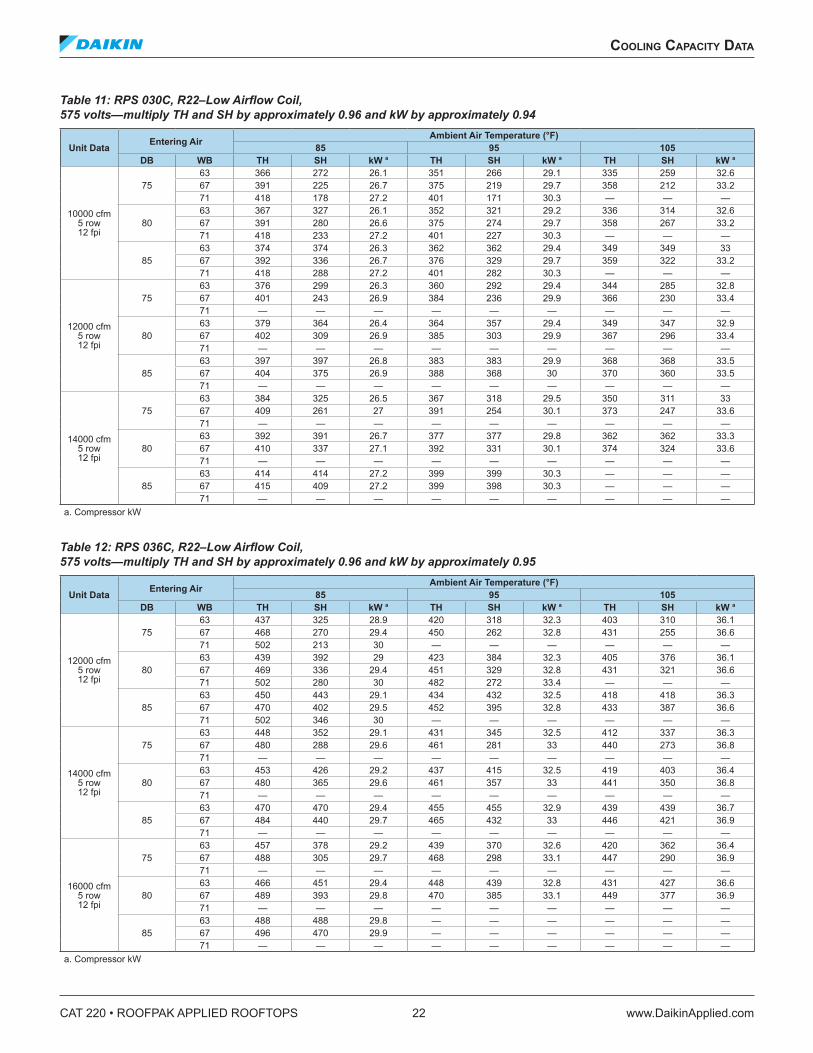
Table 11: RPS 030C, R22–Low Airflow Coil, 575 volts—multiply TH and SH by approximately 0.96 and kW by approximately 0.94
Unit Data Entering Air Ambient Air Temperature (°F)85 95 105
DB WB TH SH kW a TH SH kW a TH SH kW a
10000 cfm 5 row 12 fpi
7563 366 272 26.1 351 266 29.1 335 259 32.667 391 225 26.7 375 219 29.7 358 212 33.271 418 178 27.2 401 171 30.3 — — —
8063 367 327 26.1 352 321 29.2 336 314 32.667 391 280 26.6 375 274 29.7 358 267 33.271 418 233 27.2 401 227 30.3 — — —
8563 374 374 26.3 362 362 29.4 349 349 3367 392 336 26.7 376 329 29.7 359 322 33.271 418 288 27.2 401 282 30.3 — — —
12000 cfm 5 row 12 fpi
7563 376 299 26.3 360 292 29.4 344 285 32.867 401 243 26.9 384 236 29.9 366 230 33.471 — — — — — — — — —
8063 379 364 26.4 364 357 29.4 349 347 32.967 402 309 26.9 385 303 29.9 367 296 33.471 — — — — — — — — —
8563 397 397 26.8 383 383 29.9 368 368 33.567 404 375 26.9 388 368 30 370 360 33.571 — — — — — — — — —
14000 cfm 5 row 12 fpi
7563 384 325 26.5 367 318 29.5 350 311 3367 409 261 27 391 254 30.1 373 247 33.671 — — — — — — — — —
8063 392 391 26.7 377 377 29.8 362 362 33.367 410 337 27.1 392 331 30.1 374 324 33.671 — — — — — — — — —
8563 414 414 27.2 399 399 30.3 — — —67 415 409 27.2 399 398 30.3 — — —71 — — — — — — — — —
a. Compressor kW
Table 12: RPS 036C, R22–Low Airflow Coil, 575 volts—multiply TH and SH by approximately 0.96 and kW by approximately 0.95
Unit Data Entering Air Ambient Air Temperature (°F)85 95 105
DB WB TH SH kW a TH SH kW a TH SH kW a
12000 cfm 5 row 12 fpi
7563 437 325 28.9 420 318 32.3 403 310 36.167 468 270 29.4 450 262 32.8 431 255 36.671 502 213 30 — — — — — —
8063 439 392 29 423 384 32.3 405 376 36.167 469 336 29.4 451 329 32.8 431 321 36.671 502 280 30 482 272 33.4 — — —
8563 450 443 29.1 434 432 32.5 418 418 36.367 470 402 29.5 452 395 32.8 433 387 36.671 502 346 30 — — — — — —
14000 cfm 5 row 12 fpi
7563 448 352 29.1 431 345 32.5 412 337 36.367 480 288 29.6 461 281 33 440 273 36.871 — — — — — — — — —
8063 453 426 29.2 437 415 32.5 419 403 36.467 480 365 29.6 461 357 33 441 350 36.871 — — — — — — — — —
8563 470 470 29.4 455 455 32.9 439 439 36.767 484 440 29.7 465 432 33 446 421 36.971 — — — — — — — — —
16000 cfm 5 row 12 fpi
7563 457 378 29.2 439 370 32.6 420 362 36.467 488 305 29.7 468 298 33.1 447 290 36.971 — — — — — — — — —
8063 466 451 29.4 448 439 32.8 431 427 36.667 489 393 29.8 470 385 33.1 449 377 36.971 — — — — — — — — —
8563 488 488 29.8 — — — — — —67 496 470 29.9 — — — — — —71 — — — — — — — — —
a. Compressor kW
CoolIng CapaCITy daTa
www.DaikinApplied.com 23 CAT 220 • ROOFPAK APPLIED ROOFTOPS
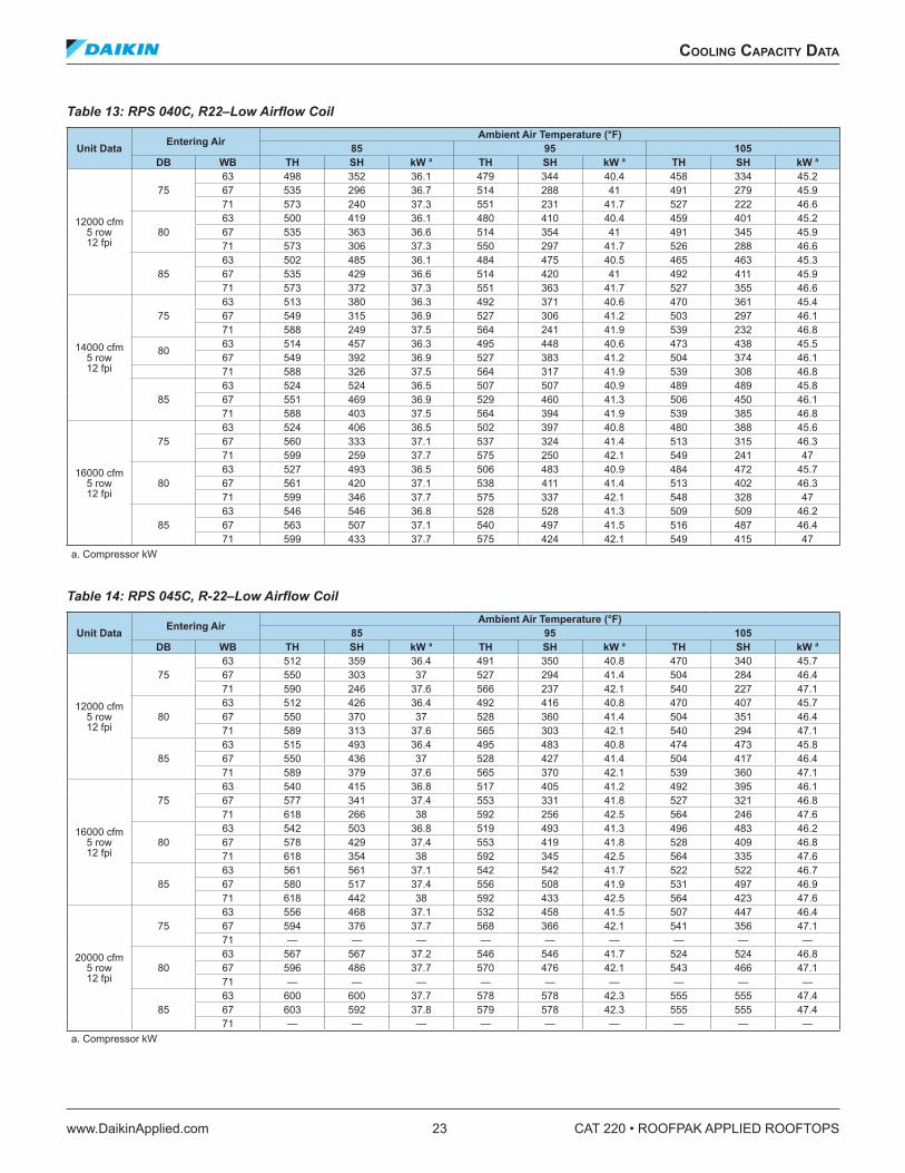
Table 13: RPS 040C, R22–Low Airflow Coil
Unit Data Entering Air Ambient Air Temperature (°F)85 95 105
DB WB TH SH kW a TH SH kW a TH SH kW a
12000 cfm 5 row 12 fpi
7563 498 352 36.1 479 344 40.4 458 334 45.267 535 296 36.7 514 288 41 491 279 45.971 573 240 37.3 551 231 41.7 527 222 46.6
8063 500 419 36.1 480 410 40.4 459 401 45.267 535 363 36.6 514 354 41 491 345 45.971 573 306 37.3 550 297 41.7 526 288 46.6
8563 502 485 36.1 484 475 40.5 465 463 45.367 535 429 36.6 514 420 41 492 411 45.971 573 372 37.3 551 363 41.7 527 355 46.6
14000 cfm 5 row 12 fpi
7563 513 380 36.3 492 371 40.6 470 361 45.467 549 315 36.9 527 306 41.2 503 297 46.171 588 249 37.5 564 241 41.9 539 232 46.8
8063 514 457 36.3 495 448 40.6 473 438 45.567 549 392 36.9 527 383 41.2 504 374 46.171 588 326 37.5 564 317 41.9 539 308 46.8
8563 524 524 36.5 507 507 40.9 489 489 45.867 551 469 36.9 529 460 41.3 506 450 46.171 588 403 37.5 564 394 41.9 539 385 46.8
16000 cfm 5 row 12 fpi
7563 524 406 36.5 502 397 40.8 480 388 45.667 560 333 37.1 537 324 41.4 513 315 46.371 599 259 37.7 575 250 42.1 549 241 47
8063 527 493 36.5 506 483 40.9 484 472 45.767 561 420 37.1 538 411 41.4 513 402 46.371 599 346 37.7 575 337 42.1 548 328 47
8563 546 546 36.8 528 528 41.3 509 509 46.267 563 507 37.1 540 497 41.5 516 487 46.471 599 433 37.7 575 424 42.1 549 415 47
a. Compressor kW
Table 14: RPS 045C, R-22–Low Airflow Coil
Unit Data Entering Air Ambient Air Temperature (°F) 85 95 105
DB WB TH SH kW a TH SH kW a TH SH kW a
12000 cfm 5 row 12 fpi
7563 512 359 36.4 491 350 40.8 470 340 45.767 550 303 37 527 294 41.4 504 284 46.471 590 246 37.6 566 237 42.1 540 227 47.1
8063 512 426 36.4 492 416 40.8 470 407 45.767 550 370 37 528 360 41.4 504 351 46.471 589 313 37.6 565 303 42.1 540 294 47.1
8563 515 493 36.4 495 483 40.8 474 473 45.867 550 436 37 528 427 41.4 504 417 46.471 589 379 37.6 565 370 42.1 539 360 47.1
16000 cfm 5 row 12 fpi
7563 540 415 36.8 517 405 41.2 492 395 46.167 577 341 37.4 553 331 41.8 527 321 46.871 618 266 38 592 256 42.5 564 246 47.6
8063 542 503 36.8 519 493 41.3 496 483 46.267 578 429 37.4 553 419 41.8 528 409 46.871 618 354 38 592 345 42.5 564 335 47.6
8563 561 561 37.1 542 542 41.7 522 522 46.767 580 517 37.4 556 508 41.9 531 497 46.971 618 442 38 592 433 42.5 564 423 47.6
20000 cfm 5 row 12 fpi
7563 556 468 37.1 532 458 41.5 507 447 46.467 594 376 37.7 568 366 42.1 541 356 47.171 — — — — — — — — —
8063 567 567 37.2 546 546 41.7 524 524 46.867 596 486 37.7 570 476 42.1 543 466 47.171 — — — — — — — — —
8563 600 600 37.7 578 578 42.3 555 555 47.467 603 592 37.8 579 578 42.3 555 555 47.471 — — — — — — — — —
a. Compressor kW
CAT 220 • ROOFPAK APPLIED ROOFTOPS 24 www.DaikinApplied.com
CoolIng CapaCITy daTa
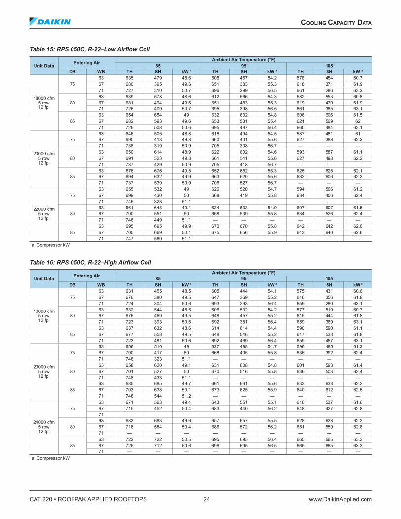
Table 15: RPS 050C, R-22–Low Airflow Coil
Unit Data Entering Air Ambient Air Temperature (°F)85 95 105
DB WB TH SH kW a TH SH kW a TH SH kW a
18000 cfm 5 row 12 fpi
7563 635 479 48.6 608 467 54.2 578 454 60.767 680 395 49.6 651 383 55.3 618 371 61.971 727 310 50.7 696 299 56.5 661 286 63.2
8063 639 578 48.6 612 566 54.3 582 553 60.867 681 494 49.6 651 483 55.3 619 470 61.971 726 409 50.7 695 398 56.5 661 385 63.1
8563 654 654 49 632 632 54.8 606 606 61.567 682 593 49.6 653 581 55.4 621 569 6271 726 508 50.6 695 497 56.4 660 484 63.1
20000 cfm 5 row 12 fpi
7563 646 505 48.8 618 494 54.5 587 481 6167 690 413 49.8 660 401 55.6 627 388 62.271 738 319 50.9 705 308 56.7 — — —
8063 650 614 48.9 622 602 54.6 593 587 61.167 691 523 49.8 661 511 55.6 627 498 62.271 737 429 50.9 705 418 56.7 — — —
8563 676 676 49.5 652 652 55.3 625 625 62.167 694 632 49.9 663 620 55.6 632 606 62.371 737 539 50.9 706 527 56.7 — — —
22000 cfm 5 row 12 fpi
7563 655 532 49 626 520 54.7 594 506 61.267 699 430 50 668 419 55.8 634 406 62.471 746 328 51.1 — — — — — —
8063 661 648 49.1 634 633 54.9 607 607 61.567 700 551 50 668 539 55.8 634 526 62.471 746 449 51.1 — — — — — —
8563 695 695 49.9 670 670 55.8 642 642 62.667 705 669 50.1 675 656 55.9 643 640 62.671 747 569 51.1 — — — — — —
a. Compressor kW
Table 16: RPS 050C, R-22–High Airflow Coil
Unit Data Entering Air Ambient Air Temperature (°F)85 95 105
DB WB TH SH kW a TH SH kW a TH SH kW a
16000 cfm 5 row 12 fpi
7563 631 455 48.5 605 444 54.1 575 431 60.667 676 380 49.5 647 369 55.2 616 356 61.871 724 304 50.6 693 293 56.4 659 280 63.1
8063 632 544 48.5 606 532 54.2 577 519 60.767 676 469 49.5 648 457 55.2 615 444 61.871 723 393 50.6 692 381 56.4 659 369 63.1
8563 637 632 48.6 614 614 54.4 590 590 61.167 677 558 49.5 648 546 55.2 617 533 61.871 723 481 50.6 692 469 56.4 659 457 63.1
20000 cfm 5 row 12 fpi
7563 656 510 49 627 498 54.7 596 485 61.267 700 417 50 668 405 55.8 636 392 62.471 748 323 51.1 — — — — — —
8063 658 620 49.1 631 608 54.8 601 593 61.467 701 527 50 670 516 55.8 636 503 62.471 748 433 51.1 — — — — — —
8563 685 685 49.7 661 661 55.6 633 633 62.367 703 638 50.1 673 625 55.9 640 612 62.571 748 544 51.2 — — — — — —
24000 cfm 5 row 12 fpi
7563 671 563 49.4 643 551 55.1 610 537 61.667 715 452 50.4 683 440 56.2 648 427 62.871 — — — — — — — — —
8063 683 683 49.6 657 657 55.5 628 628 62.267 718 584 50.4 686 572 56.2 651 559 62.871 — — — — — — — — —
8563 722 722 50.5 695 695 56.4 665 665 63.367 725 712 50.6 696 695 56.5 665 665 63.371 — — — — — — — — —
a. Compressor kW
CoolIng CapaCITy daTa
www.DaikinApplied.com 25 CAT 220 • ROOFPAK APPLIED ROOFTOPS
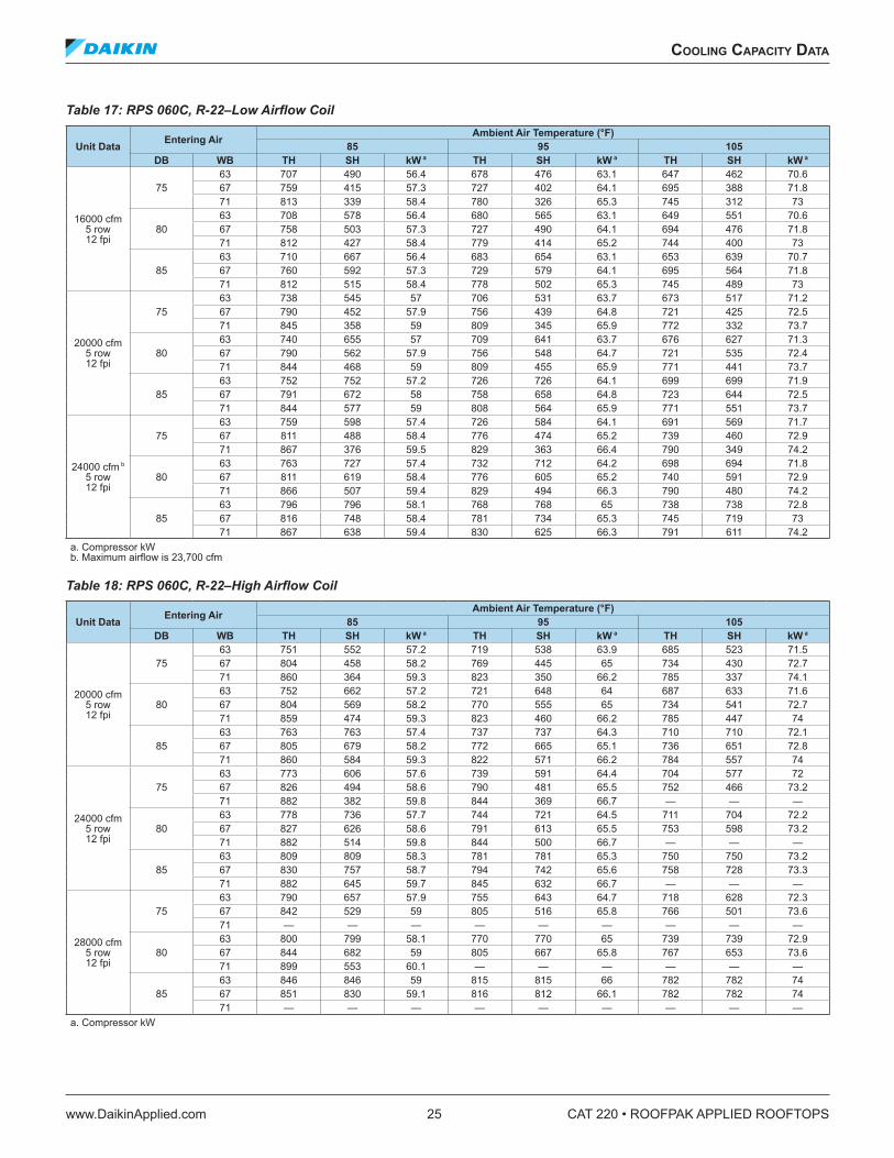
Table 17: RPS 060C, R-22–Low Airflow Coil
Unit Data Entering Air Ambient Air Temperature (°F) 85 95 105
DB WB TH SH kW a TH SH kW a TH SH kW a
16000 cfm 5 row 12 fpi
7563 707 490 56.4 678 476 63.1 647 462 70.667 759 415 57.3 727 402 64.1 695 388 71.871 813 339 58.4 780 326 65.3 745 312 73
8063 708 578 56.4 680 565 63.1 649 551 70.667 758 503 57.3 727 490 64.1 694 476 71.871 812 427 58.4 779 414 65.2 744 400 73
8563 710 667 56.4 683 654 63.1 653 639 70.767 760 592 57.3 729 579 64.1 695 564 71.871 812 515 58.4 778 502 65.3 745 489 73
20000 cfm 5 row 12 fpi
7563 738 545 57 706 531 63.7 673 517 71.267 790 452 57.9 756 439 64.8 721 425 72.571 845 358 59 809 345 65.9 772 332 73.7
8063 740 655 57 709 641 63.7 676 627 71.367 790 562 57.9 756 548 64.7 721 535 72.471 844 468 59 809 455 65.9 771 441 73.7
8563 752 752 57.2 726 726 64.1 699 699 71.967 791 672 58 758 658 64.8 723 644 72.571 844 577 59 808 564 65.9 771 551 73.7
24000 cfm b 5 row 12 fpi
7563 759 598 57.4 726 584 64.1 691 569 71.767 811 488 58.4 776 474 65.2 739 460 72.971 867 376 59.5 829 363 66.4 790 349 74.2
8063 763 727 57.4 732 712 64.2 698 694 71.867 811 619 58.4 776 605 65.2 740 591 72.971 866 507 59.4 829 494 66.3 790 480 74.2
8563 796 796 58.1 768 768 65 738 738 72.867 816 748 58.4 781 734 65.3 745 719 7371 867 638 59.4 830 625 66.3 791 611 74.2
a. Compressor kW b. Maximum airflow is 23,700 cfm
Table 18: RPS 060C, R-22–High Airflow Coil
Unit Data Entering Air Ambient Air Temperature (°F)85 95 105
DB WB TH SH kW a TH SH kW a TH SH kW a
20000 cfm 5 row 12 fpi
7563 751 552 57.2 719 538 63.9 685 523 71.567 804 458 58.2 769 445 65 734 430 72.771 860 364 59.3 823 350 66.2 785 337 74.1
8063 752 662 57.2 721 648 64 687 633 71.667 804 569 58.2 770 555 65 734 541 72.771 859 474 59.3 823 460 66.2 785 447 74
8563 763 763 57.4 737 737 64.3 710 710 72.167 805 679 58.2 772 665 65.1 736 651 72.871 860 584 59.3 822 571 66.2 784 557 74
24000 cfm 5 row 12 fpi
7563 773 606 57.6 739 591 64.4 704 577 7267 826 494 58.6 790 481 65.5 752 466 73.271 882 382 59.8 844 369 66.7 — — —
8063 778 736 57.7 744 721 64.5 711 704 72.267 827 626 58.6 791 613 65.5 753 598 73.271 882 514 59.8 844 500 66.7 — — —
8563 809 809 58.3 781 781 65.3 750 750 73.267 830 757 58.7 794 742 65.6 758 728 73.371 882 645 59.7 845 632 66.7 — — —
28000 cfm 5 row 12 fpi
7563 790 657 57.9 755 643 64.7 718 628 72.367 842 529 59 805 516 65.8 766 501 73.671 — — — — — — — — —
8063 800 799 58.1 770 770 65 739 739 72.967 844 682 59 805 667 65.8 767 653 73.671 899 553 60.1 — — — — — —
8563 846 846 59 815 815 66 782 782 7467 851 830 59.1 816 812 66.1 782 782 7471 — — — — — — — — —
a. Compressor kW
CAT 220 • ROOFPAK APPLIED ROOFTOPS 26 www.DaikinApplied.com
CoolIng CapaCITy daTa
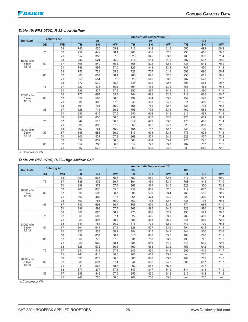
Table 19: RPS 070C, R-22–Low Airflow
Unit Data Entering Air Ambient Air Temperature (°F)85 95 105
DB WB TH SH kW a TH SH kW a TH SH kW a
18000 cfm 5 row 12 fpi
7563 745 526 55.2 716 512 61.8 685 499 69.267 799 442 56.1 768 430 62.8 735 416 70.371 857 358 57.0 823 345 63.8 788 332 71.4
8063 747 624 55.2 718 611 61.8 687 597 69.267 798 540 56.1 768 528 62.8 735 514 70.271 856 456 57.0 823 443 63.8 787 430 71.3
8563 750 721 55.3 722 707 61.9 693 690 69.467 800 639 56.1 768 626 62.8 735 612 70.271 855 554 57.0 823 542 63.8 787 528 71.3
22000 cfm 5 row 12 fpi
7563 772 579 55.6 741 565 62.3 708 551 69.767 827 478 56.5 794 465 63.2 758 451 70.871 886 377 57.5 850 364 64.3 812 350 71.9
8063 775 697 55.7 744 683 62.3 712 668 69.767 827 598 56.5 794 584 63.2 759 570 70.771 885 496 57.5 849 483 64.3 811 469 71.9
8563 791 791 55.9 765 765 62.7 738 738 70.367 828 715 56.5 795 702 63.3 760 688 70.871 886 615 57.5 850 602 64.3 812 588 71.9
26000 cfm 5 row 12 fpi
7563 792 630 56.0 759 616 62.6 725 601 70.167 847 513 56.9 812 499 63.6 775 485 71.171 906 395 57.9 869 382 64.7 829 368 72.2
8063 797 764 56.0 765 747 62.7 733 729 70.267 848 652 56.9 813 638 63.6 776 624 71.171 906 534 57.9 868 521 64.6 829 507 72.2
8563 832 832 56.6 804 804 63.4 775 775 71.167 852 788 56.9 817 773 63.7 782 757 71.271 907 673 57.8 869 660 64.6 830 646 72.2
a. Compressor kW
Table 20: RPS 070C, R-22–High Airflow Coil
Unit Data Entering Air Ambient Air Temperature (°F) 85 95 105
DB WB TH SH kW a TH SH kW a TH SH kW a
20000 cfm 5 row 12 fpi
7563 782 565 55.8 750 552 62.5 717 537 69.967 838 472 56.7 804 459 63.4 768 444 71.071 898 378 57.7 862 364 64.5 823 350 72.1
8063 785 676 55.8 752 662 62.5 719 647 69.967 838 583 56.7 805 569 63.4 769 555 70.971 897 488 57.7 861 474 64.5 823 460 72.1
8563 790 784 55.9 763 763 62.7 736 736 70.367 840 693 56.7 806 679 63.5 771 665 71.071 898 599 57.7 862 585 64.5 822 570 72.1
24000 cfm 5 row 12 fpi
7563 806 620 56.2 773 606 62.9 738 591 70.367 863 509 57.1 827 495 63.9 789 480 71.471 923 397 58.2 885 383 65.0 844 369 72.6
8063 811 751 56.2 778 736 62.9 743 720 70.467 864 641 57.1 828 627 63.9 791 612 71.471 923 528 58.1 884 515 64.9 844 500 72.6
8563 837 837 56.7 810 810 63.5 780 780 71.267 866 772 57.2 831 758 63.9 793 742 71.571 922 660 58.1 884 646 64.9 845 632 72.6
28000 cfm 5 row 12 fpi
7563 825 672 56.5 790 658 63.2 753 642 70.667 881 544 57.4 843 530 64.2 805 515 71.771 941 415 58.5 901 401 65.3 — 207 —
8063 833 819 56.6 800 800 63.3 769 769 71.067 883 697 57.4 844 682 64.2 805 667 71.771 941 567 58.5 902 554 65.3 — 207 —
8563 877 877 57.4 847 847 64.2 814 814 71.967 889 846 57.5 853 830 64.3 816 812 71.971 942 720 58.5 902 706 65.3 — 207 —
a. Compressor kW

CoolIng CapaCITy daTa
www.DaikinApplied.com 27 CAT 220 • ROOFPAK APPLIED ROOFTOPS
Table 21: RPS 075C, R-22–Low Airflow Coil
Unit Data Entering Air Ambient Air Temperature (°F)85 95 105
DB WB TH SH kW a TH SH kW a TH SH kW a
18000 cfm 5 row 10 fpi
7563 848 573 68.5 816 558 76.4 780 542 85.467 910 490 69.6 876 475 77.6 839 459. 86.871 977 405 70.8 941 391 78.9 900 375 88.1
8063 848 672 68.5 817 657 76.4 782 641 85.467 909 588 69.6 876 574 77.6 839 557 86.771 976 503 70.8 939 489 78.9 899 473 88.1
8563 850 770 68.5 819 755 76.4 784 738 85.567 910 687 69.6 876 672 77.6 839 656 86.771 976 602 70.8 939 587 78.9 899 571 88.1
22000 cfm 5 row 10 fpi
7563 884 628 69.1 849 613 77.1 812 596 86.267 948 528 70.3 911 512 78.3 871 496 87.571 1016 425 71.5 976 411 79.6 933 394 88.9
8063 885 747 69.1 851 732 77.1 813 715 86.267 948 647 70.3 911 631 78.3 871 615 87.571 1015 544 71.5 975 529 79.6 932 513 88.9
8563 890 863 69.2 857 845 77.2 823 823 86.467 948 766 70.3 912 750 78.3 872 734 87.571 1015 663 71.5 975 648 79.6 932 632 88.9
26000 cfm b 5 row 10 fpi
7563 911 681 69.6 874 665 77.6 835 648 86.767 975 563 70.8 936 547 78.8 894 531 88.071 1044 444 72.0 1002 429 80.2 956 412 89.4
8063 913 818 69.6 877 802 77.6 837 784 86.767 975 702 70.8 937 687 78.8 895 670. 88.071 1043 583 72.0 1001 568 80.1 956 551 89.4
8563 930 930 69.9 900 900 78.1 867 867 87.467 977 840 70.8 938 825 78.8 896 807 88.071 1042 722 72.0 1002. 707 80.1 957 691 89.4
a. Compressor kW b. Maximum airflow is 25,675 cfm
Table 22: RPS 075C, R-22–High Airflow Coil
Unit Data Entering Air Ambient Air Temperature (°F)85 95 105
DB WB TH SH kW a TH SH kW a TH SH kW a
22000 cfm 5 row 10 fpi
7563 905 640 69.5 870 624 77.5 831 607 86.667 97 538 70.7 933 523 78.8 892 506 88.071 1040 435 72.0 1000 420 80.1 955 403 89.4
8063 907 760 69.5 872 744 77.5 833 727 86.667 970 658 70.7 933 642 78.7 891 625 87.971 1039 555 72.0 999 539 80.1 954 523 89.4
8563 912 878 69.6 878 861 77.6 842 840 86.867 972 779 70.7 933 762 78.7 892 745 87.971 1038 674 72.0 999 659 80.1 954 643 89.4
26000 cfm 5 row 10 fpi
7563 933 693 70.0 896 677 78.0 855 659 87.167 999 574 71.2 959 558 79.3 915 541 88.571 1070 454 72.5 1026 438 80.7 980 421 90.0
8063 936 833 70.0 899 817 78.0 859 798 87.267 999 715 71.2 959 699 79.3 916 682 88.571 1069 594 72.5 1026 579 80.6 979 562 89.9
8563 952 952 70.3 921 921 78.5 887 887 87.867 1000 855 71.2 961 838 79.3 917 821 88.571 1069 735 72.5 1026 720 80.6 979 703 89.9
30000 cfm 5 row 10 fpi
7563 954 744 70.4 915 728 78.4 873 710 87.667 1021 609 71.6 979 593 79.7 934 575 88.971 1091 472 72.9 1047 456 81.1 998 439 90.4
8063 959 901 70.5 920 883 78.5 880 863 87.767 1021 770 71.6 979 753 79.7 934 736 88.971 1091 632 72.9 1046 617 81.0 998 600 90.4
8563 994 994 71.1 962 962 79.3 925 925 88.767 1025 928 71.7 984 911 79.8 939 891 89.071 1091 794 72.9 1047 778 81.0 998 761 90.3
a. Compressor kW
CAT 220 • ROOFPAK APPLIED ROOFTOPS 28 www.DaikinApplied.com
heaTIng CapaCITy daTa
heaTIng CapaCITy daTa
Gas HeatFigure 13: Gas Heat Capacity
Table 23: RPS 015C to 135C–Gas Furnace Air Temperature Rise (°F)
Unit SizeNominal Airflow (cfm)
Furnace Size (MBh Output)a
200 250 320 400 500 640 650 790 800 1000
015C 7000 26.3 32.9 42.1 52.7 65.8 — 85.6 — — —020C 8000 23.0 28.8 36.9 46.1 57.6 — 74.9 — 92.2 —025C 10000 18.4 23.0 29.5 36.9 46.1 59.0 59.9 — 73.7 —030C 12000 15.4 19.2 24.6 30.7 38.4 49.2 49.9 60.7 61.4 —036C 14000 13.2 16.5 21.1 26.3 32.9 42.1 42.8 52.0 52.7 —040C 16000 11.5 14.4 18.4 23.0 28.8 36.9 37.4 45.5 46.1 57.6045C 16000 11.5 14.4 18.4 23.0 28.8 36.9 37.4 45.5 46.1 57.6050C 20000 9.2 11.5 14.7 18.4 23.0 29.5 30.0 36.4 36.9 46.1060C 24000 7.7 9.6 12.3 15.4 19.2 24.6 25.0 30.3 30.7 38.4070C 28000 6.6 8.2 10.5 13.2 16.5 21.1 21.4 26.0 26.3 32.9075C 30000 6.1 7.7 9.8 12.3 15.4 19.7 20.0 24.3 24.6 30.7080C 32000 — — — — 14.4 18.4 18.7 22.8 23.0 28.8090C 36000 — — — — 12.8 16.4 16.6 20.2 20.5 25.6105C 40000 — — — — 11.5 14.7 15.0 18.2 18.4 23.0115C 46000 — — — — 10.0 12.8 13.0 15.8 16.0 20.0125C 48000 — — — — 9.6 12.3 12.5 15.2 15.4 19.2135C 50000 — — — — 9.2 11.8 12.0 14.6 14.7 18.4
a. Output is 80% of input.
4 5 6 7 8 9 10 15 20 30 401 1.5 2 3
200
300
400
500
600
700
8009001000
1500
2000
Minimum CFM x 1000
MBHOutput
Model 200
Model 250
Model 320
Model 400
Model 640
Model 500
Model 650
Model 790Model 800
Model 1000
The intersection of CFM andMBH must fall on or belowfurnace model line
p20
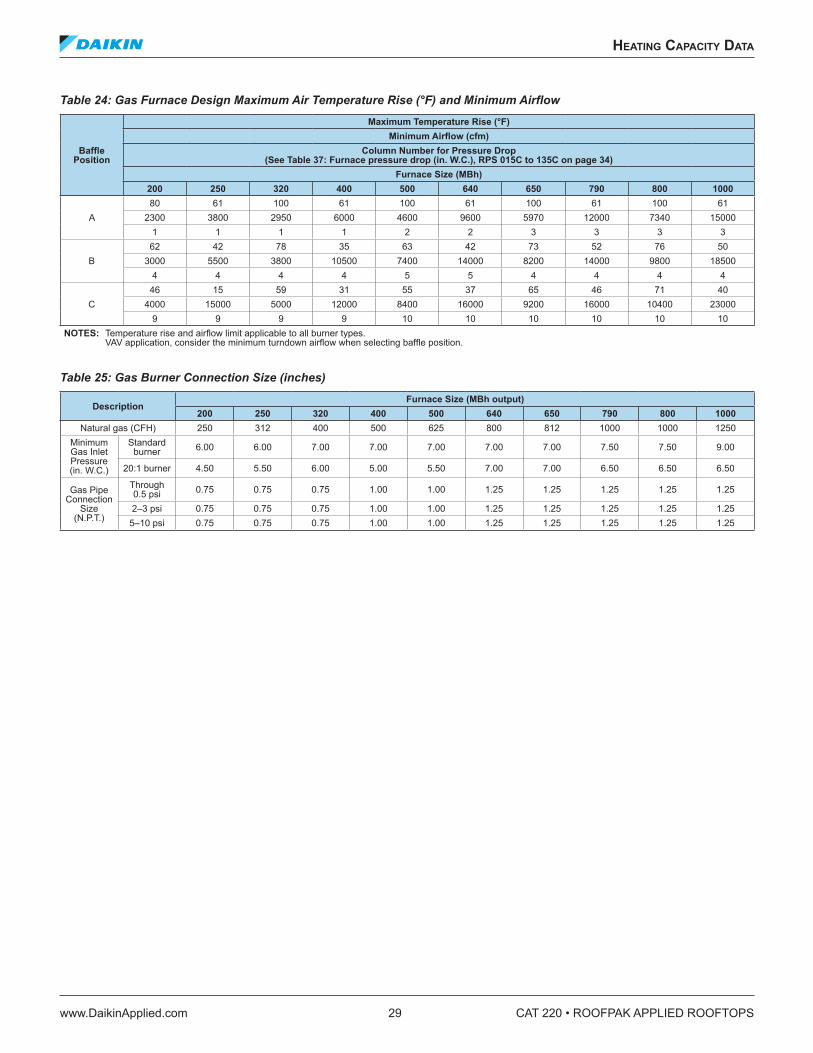
heaTIng CapaCITy daTa
www.DaikinApplied.com 29 CAT 220 • ROOFPAK APPLIED ROOFTOPS
Table 24: Gas Furnace Design Maximum Air Temperature Rise (°F) and Minimum Airflow
Baffle Position
Maximum Temperature Rise (°F)Minimum Airflow (cfm)
Column Number for Pressure Drop (See Table 37: Furnace pressure drop (in . W .C .), RPS 015C to 135C on page 34)
Furnace Size (MBh)200 250 320 400 500 640 650 790 800 1000
A80 61 100 61 100 61 100 61 100 61
2300 3800 2950 6000 4600 9600 5970 12000 7340 150001 1 1 1 2 2 3 3 3 3
B62 42 78 35 63 42 73 52 76 50
3000 5500 3800 10500 7400 14000 8200 14000 9800 185004 4 4 4 5 5 4 4 4 4
C46 15 59 31 55 37 65 46 71 40
4000 15000 5000 12000 8400 16000 9200 16000 10400 230009 9 9 9 10 10 10 10 10 10
NOTES: Temperature rise and airflow limit applicable to all burner types. VAV application, consider the minimum turndown airflow when selecting baffle position.
Table 25: Gas Burner Connection Size (inches)
DescriptionFurnace Size (MBh output)
200 250 320 400 500 640 650 790 800 1000Natural gas (CFH) 250 312 400 500 625 800 812 1000 1000 1250
Minimum Gas Inlet Pressure (in. W.C.)
Standard burner 6.00 6.00 7.00 7.00 7.00 7.00 7.00 7.50 7.50 9.00
20:1 burner 4.50 5.50 6.00 5.00 5.50 7.00 7.00 6.50 6.50 6.50
Gas Pipe Connection
Size (N.P.T.)
Through 0.5 psi 0.75 0.75 0.75 1.00 1.00 1.25 1.25 1.25 1.25 1.25
2–3 psi 0.75 0.75 0.75 1.00 1.00 1.25 1.25 1.25 1.25 1.255–10 psi 0.75 0.75 0.75 1.00 1.00 1.25 1.25 1.25 1.25 1.25
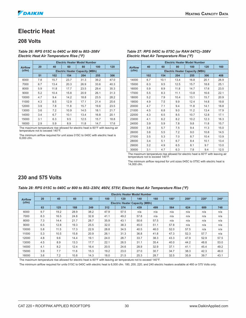
CAT 220 • ROOFPAK APPLIED ROOFTOPS 30 www.DaikinApplied.com
heaTIng CapaCITy daTa
Electric Heat208 Volts
Table 26: RPS 015C to 040C or 800 to 802–208V Electric Heat Air Temperature Rise (°F)
Airflow (cfm)
Electric Heater Model Number20 40 60 80 100 120
Electric Heater Capacity (MBh)51 102 154 204 255 306
6000 7.8 15.7 23.7 31.3 39.2 47.07000 6.7 13.4 20.3 26.9 33.6 40.38000 5.9 11.8 17.7 23.5 29.4 35.39000 5.2 10.4 15.8 20.9 26.1 31.3
10000 4.7 9.4 14.2 18.8 23.5 28.211000 4.3 8.5 12.9 17.1 21.4 25.612000 3.9 7.8 11.8 15.7 19.6 23.513000 3.6 7.2 10.9 14.5 18.1 21.714000 3.4 6.7 10.1 13.4 16.8 20.115000 3.1 6.3 9.5 12.5 15.7 18.816000 2.9 5.9 8.9 11.8 14.7 17.6
The maximum temperature rise allowed for electric heat is 60°F with leaving air temperature not to exceed 140°F. The minimum airflow required for unit sizes 015C to 040C with electric heat is 6,000 cfm.
Table 27: RPS 045C to 075C (or RAH 047C)–208V Electric Heat Air Temperature Rise (°F)
Airflow (cfm)
Electric Heater Model Number40 60 80 100 120 160
Electric Heater Capacity (MBh)102 154 204 255 306 408
14000 6.7 10.1 13.4 16.8 20.1 26.915000 6.3 9.5 12.5 15.7 18.8 25.116000 5.9 8.9 11.8 14.7 17.6 23.517000 5.5 8.3 11.1 13.8 16.6 22.118000 5.2 7.9 10.4 13.1 15.7 20.919000 4.9 7.5 9.9 12.4 14.8 19.820000 4.7 7.1 9.4 11.8 14.1 18.821000 4.5 6.8 9.0 11.2 13.4 17.922000 4.3 6.5 8.5 10.7 12.8 17.123000 4.1 6.2 8.2 10.2 12.3 16.324000 3.9 5.9 7.8 9.8 11.8 15.725000 3.8 5.7 7.5 9.4 11.3 15.026000 3.6 5.5 7.2 9.0 10.8 14.527000 3.5 5.3 7.0 8.7 10.4 13.928000 3.4 5.1 6.7 8.4 10.1 13.429000 3.2 4.9 6.5 8.1 9.7 13.030000 3.1 4.7 6.3 7.8 9.4 12.5
The maximum temperature rise allowed for electric heat is 60°F with leaving air temperature not to exceed 140°F. The minimum airflow required for unit sizes 045C to 075C with electric heat is 14,000 cfm.
230 and 575 Volts
Table 28: RPS 015C to 040C or 800 to 802–230V, 460V, 575V; Electric Heat Air Temperature Rise (°F)
Airflow (cfm)
Electric Heater Model Number20 40 60 80 100 120 140 160 180* 200* 220* 240*
Electric Heater Capacity (MBh)63 125 188 249 312 374 439 499 564 624 689 748
6000 9.7 19.2 28.9 38.2 47.9 57.5 n/a n/a n/a n/a n/a n/a7000 8.3 16.5 24.8 32.8 41.1 49.2 57.8 n/a n/a n/a n/a n/a8000 7.3 14.4 21.7 28.7 35.9 43.1 50.6 57.5 n/a n/a n/a n/a9000 6.5 12.8 19.3 25.5 32.0 38.3 45.0 51.1 57.8 n/a n/a n/a
10000 5.8 11.5 17.3 22.9 28.8 34.5 40.5 46.0 52.0 57.5 n/a n/a11000 5.3 10.5 15.8 20.9 26.1 31.3 36.8 41.8 47.3 52.3 57.7 n/a12000 4.8 9.6 14.4 19.1 24.0 28.7 33.7 38.3 43.3 47.9 52.9 57.513000 4.5 8.9 13.3 17.7 22.1 26.5 31.1 35.4 40.0 44.2 48.8 53.014000 4.1 8.2 12.4 16.4 20.5 24.6 28.9 32.9 37.1 41.1 45.4 49.215000 3.9 7.7 11.6 15.3 19.2 23.0 27.0 30.7 34.7 38.3 42.3 46.016000 3.6 7.2 10.8 14.3 18.0 21.5 25.3 28.7 32.5 35.9 39.7 43.1
The maximum temperature rise allowed for electric heat is 60°F with leaving air temperature not to exceed 140°F. The minimum airflow required for units 015C to 040C with electric heat is 6,000 cfm. 180, 200, 220, and 240 electric heaters available at 460 or 575 Volts only.
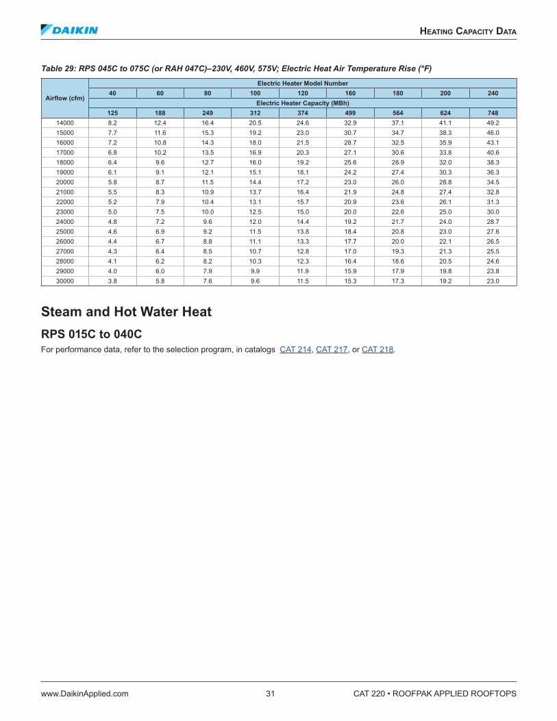
heaTIng CapaCITy daTa
www.DaikinApplied.com 31 CAT 220 • ROOFPAK APPLIED ROOFTOPS
Table 29: RPS 045C to 075C (or RAH 047C)–230V, 460V, 575V; Electric Heat Air Temperature Rise (°F)
Airflow (cfm)
Electric Heater Model Number40 60 80 100 120 160 180 200 240
Electric Heater Capacity (MBh)125 188 249 312 374 499 564 624 748
14000 8.2 12.4 16.4 20.5 24.6 32.9 37.1 41.1 49.215000 7.7 11.6 15.3 19.2 23.0 30.7 34.7 38.3 46.016000 7.2 10.8 14.3 18.0 21.5 28.7 32.5 35.9 43.117000 6.8 10.2 13.5 16.9 20.3 27.1 30.6 33.8 40.618000 6.4 9.6 12.7 16.0 19.2 25.6 28.9 32.0 38.319000 6.1 9.1 12.1 15.1 18.1 24.2 27.4 30.3 36.320000 5.8 8.7 11.5 14.4 17.2 23.0 26.0 28.8 34.521000 5.5 8.3 10.9 13.7 16.4 21.9 24.8 27.4 32.822000 5.2 7.9 10.4 13.1 15.7 20.9 23.6 26.1 31.323000 5.0 7.5 10.0 12.5 15.0 20.0 22.6 25.0 30.024000 4.8 7.2 9.6 12.0 14.4 19.2 21.7 24.0 28.725000 4.6 6.9 9.2 11.5 13.8 18.4 20.8 23.0 27.626000 4.4 6.7 8.8 11.1 13.3 17.7 20.0 22.1 26.527000 4.3 6.4 8.5 10.7 12.8 17.0 19.3 21.3 25.528000 4.1 6.2 8.2 10.3 12.3 16.4 18.6 20.5 24.629000 4.0 6.0 7.9 9.9 11.9 15.9 17.9 19.8 23.830000 3.8 5.8 7.6 9.6 11.5 15.3 17.3 19.2 23.0
Steam and Hot Water Heat RPS 015C to 040C For performance data, refer to the selection program, in catalogs CAT 214, CAT 217, or CAT 218.
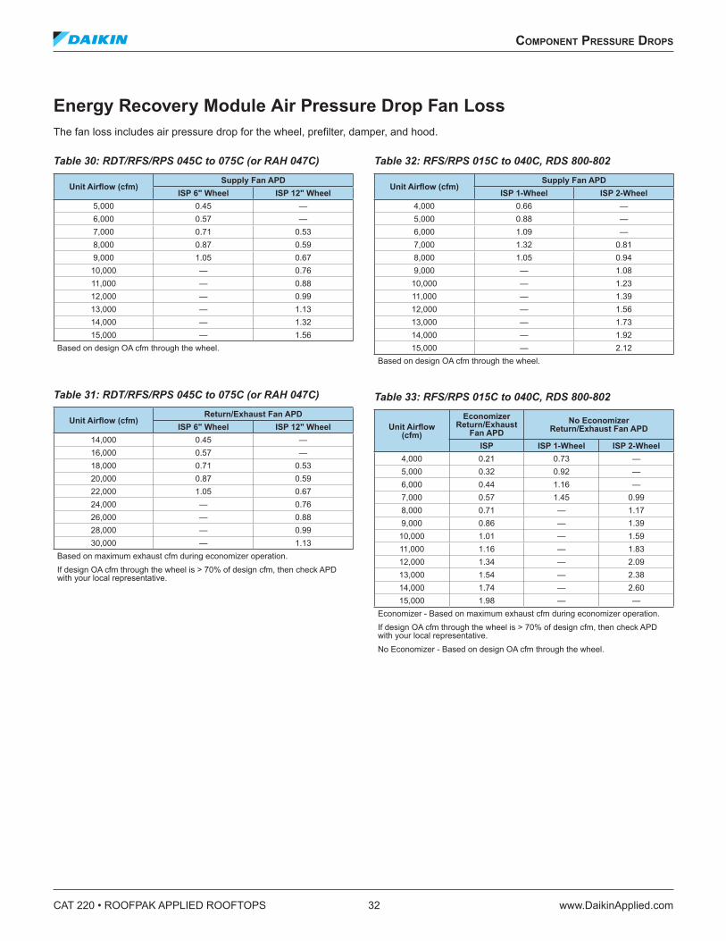
CAT 220 • ROOFPAK APPLIED ROOFTOPS 32 www.DaikinApplied.com
ComponenT pressure drops
ComponenT pressure drops
Energy Recovery Module Air Pressure Drop Fan LossThe fan loss includes air pressure drop for the wheel, prefilter, damper, and hood.
Table 30: RDT/RFS/RPS 045C to 075C (or RAH 047C)
Unit Airflow (cfm)Supply Fan APD
ISP 6" Wheel ISP 12" Wheel5,000 0.45 —6,000 0.57 —7,000 0.71 0.538,000 0.87 0.599,000 1.05 0.67
10,000 — 0.7611,000 — 0.8812,000 — 0.9913,000 — 1.1314,000 — 1.3215,000 — 1.56
Based on design OA cfm through the wheel.
Table 31: RDT/RFS/RPS 045C to 075C (or RAH 047C)
Unit Airflow (cfm) Return/Exhaust Fan APD
ISP 6" Wheel ISP 12" Wheel 14,000 0.45 —16,000 0.57 —18,000 0.71 0.5320,000 0.87 0.5922,000 1.05 0.6724,000 — 0.7626,000 — 0.8828,000 — 0.9930,000 — 1.13
Based on maximum exhaust cfm during economizer operation. If design OA cfm through the wheel is > 70% of design cfm, then check APD with your local representative.
Table 32: RFS/RPS 015C to 040C, RDS 800-802
Unit Airflow (cfm)Supply Fan APD
ISP 1-Wheel ISP 2-Wheel 4,000 0.66 —5,000 0.88 —6,000 1.09 —7,000 1.32 0.818,000 1.05 0.949,000 — 1.08
10,000 — 1.2311,000 — 1.3912,000 — 1.5613,000 — 1.7314,000 — 1.9215,000 — 2.12
Based on design OA cfm through the wheel.
Table 33: RFS/RPS 015C to 040C, RDS 800-802
Unit Airflow (cfm)
Economizer Return/Exhaust
Fan APDNo Economizer
Return/Exhaust Fan APD
ISP ISP 1-Wheel ISP 2-Wheel 4,000 0.21 0.73 —5,000 0.32 0.92 —6,000 0.44 1.16 —7,000 0.57 1.45 0.998,000 0.71 — 1.179,000 0.86 — 1.39
10,000 1.01 — 1.5911,000 1.16 — 1.8312,000 1.34 — 2.0913,000 1.54 — 2.3814,000 1.74 — 2.6015,000 1.98 — —
Economizer - Based on maximum exhaust cfm during economizer operation. If design OA cfm through the wheel is > 70% of design cfm, then check APD with your local representative. No Economizer - Based on design OA cfm through the wheel.
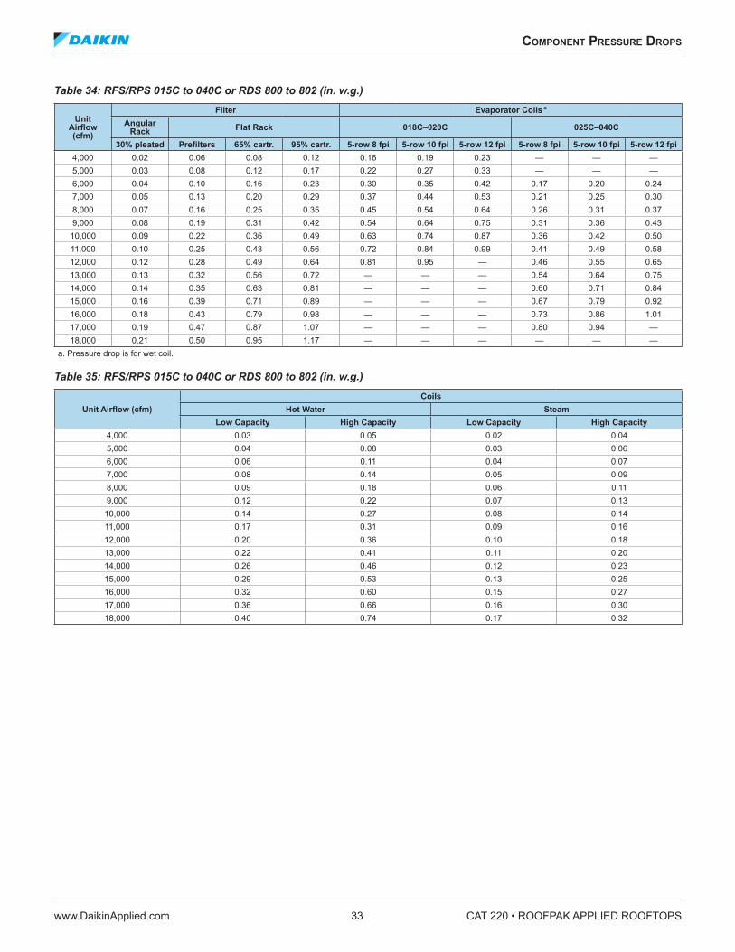
ComponenT pressure drops
www.DaikinApplied.com 33 CAT 220 • ROOFPAK APPLIED ROOFTOPS
Table 34: RFS/RPS 015C to 040C or RDS 800 to 802 (in. w.g.)
Unit Airflow (cfm)
Filter Evaporator Coils a
Angular Rack Flat Rack 018C–020C 025C–040C
30% pleated Prefilters 65% cartr . 95% cartr . 5-row 8 fpi 5-row 10 fpi 5-row 12 fpi 5-row 8 fpi 5-row 10 fpi 5-row 12 fpi 4,000 0.02 0.06 0.08 0.12 0.16 0.19 0.23 — — —5,000 0.03 0.08 0.12 0.17 0.22 0.27 0.33 — — —6,000 0.04 0.10 0.16 0.23 0.30 0.35 0.42 0.17 0.20 0.247,000 0.05 0.13 0.20 0.29 0.37 0.44 0.53 0.21 0.25 0.308,000 0.07 0.16 0.25 0.35 0.45 0.54 0.64 0.26 0.31 0.379,000 0.08 0.19 0.31 0.42 0.54 0.64 0.75 0.31 0.36 0.43
10,000 0.09 0.22 0.36 0.49 0.63 0.74 0.87 0.36 0.42 0.5011,000 0.10 0.25 0.43 0.56 0.72 0.84 0.99 0.41 0.49 0.5812,000 0.12 0.28 0.49 0.64 0.81 0.95 — 0.46 0.55 0.6513,000 0.13 0.32 0.56 0.72 — — — 0.54 0.64 0.7514,000 0.14 0.35 0.63 0.81 — — — 0.60 0.71 0.8415,000 0.16 0.39 0.71 0.89 — — — 0.67 0.79 0.9216,000 0.18 0.43 0.79 0.98 — — — 0.73 0.86 1.0117,000 0.19 0.47 0.87 1.07 — — — 0.80 0.94 —18,000 0.21 0.50 0.95 1.17 — — — — — —
a. Pressure drop is for wet coil.
Table 35: RFS/RPS 015C to 040C or RDS 800 to 802 (in. w.g.)
Unit Airflow (cfm) Coils
Hot Water SteamLow Capacity High Capacity Low Capacity High Capacity
4,000 0.03 0.05 0.02 0.045,000 0.04 0.08 0.03 0.066,000 0.06 0.11 0.04 0.077,000 0.08 0.14 0.05 0.098,000 0.09 0.18 0.06 0.119,000 0.12 0.22 0.07 0.13
10,000 0.14 0.27 0.08 0.1411,000 0.17 0.31 0.09 0.1612,000 0.20 0.36 0.10 0.1813,000 0.22 0.41 0.11 0.2014,000 0.26 0.46 0.12 0.2315,000 0.29 0.53 0.13 0.2516,000 0.32 0.60 0.15 0.2717,000 0.36 0.66 0.16 0.3018,000 0.40 0.74 0.17 0.32
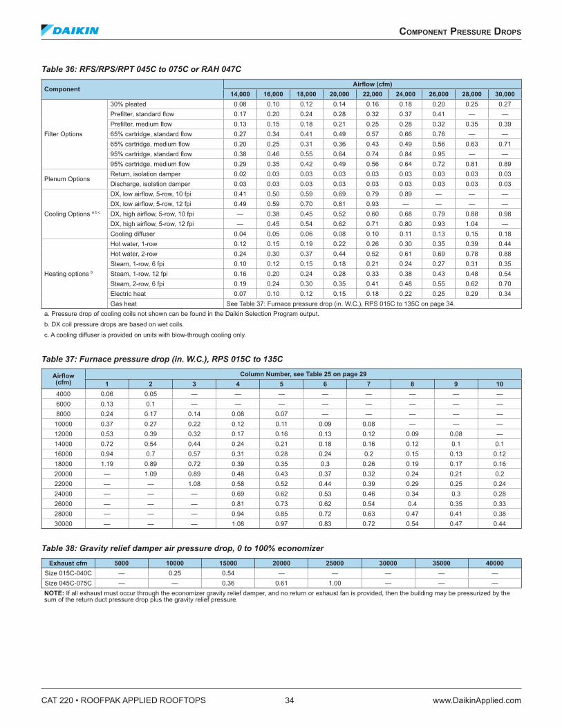
CAT 220 • ROOFPAK APPLIED ROOFTOPS 34 www.DaikinApplied.com
ComponenT pressure drops
Table 36: RFS/RPS/RPT 045C to 075C or RAH 047C
ComponentAirflow (cfm)
14,000 16,000 18,000 20,000 22,000 24,000 26,000 28,000 30,000
Filter Options
30% pleated 0.08 0.10 0.12 0.14 0.16 0.18 0.20 0.25 0.27Prefilter, standard flow 0.17 0.20 0.24 0.28 0.32 0.37 0.41 — —Prefilter, medium flow 0.13 0.15 0.18 0.21 0.25 0.28 0.32 0.35 0.3965% cartridge, standard flow 0.27 0.34 0.41 0.49 0.57 0.66 0.76 — —65% cartridge, medium flow 0.20 0.25 0.31 0.36 0.43 0.49 0.56 0.63 0.7195% cartridge, standard flow 0.38 0.46 0.55 0.64 0.74 0.84 0.95 — —95% cartridge, medium flow 0.29 0.35 0.42 0.49 0.56 0.64 0.72 0.81 0.89
Plenum Options Return, isolation damper 0.02 0.03 0.03 0.03 0.03 0.03 0.03 0.03 0.03Discharge, isolation damper 0.03 0.03 0.03 0.03 0.03 0.03 0.03 0.03 0.03
Cooling Options a b c
DX, low airflow, 5-row, 10 fpi 0.41 0.50 0.59 0.69 0.79 0.89 — — —DX, low airflow, 5-row, 12 fpi 0.49 0.59 0.70 0.81 0.93 — — — —DX, high airflow, 5-row, 10 fpi — 0.38 0.45 0.52 0.60 0.68 0.79 0.88 0.98DX, high airflow, 5-row, 12 fpi — 0.45 0.54 0.62 0.71 0.80 0.93 1.04 —Cooling diffuser 0.04 0.05 0.06 0.08 0.10 0.11 0.13 0.15 0.18
Heating options b
Hot water, 1-row 0.12 0.15 0.19 0.22 0.26 0.30 0.35 0.39 0.44Hot water, 2-row 0.24 0.30 0.37 0.44 0.52 0.61 0.69 0.78 0.88Steam, 1-row, 6 fpi 0.10 0.12 0.15 0.18 0.21 0.24 0.27 0.31 0.35Steam, 1-row, 12 fpi 0.16 0.20 0.24 0.28 0.33 0.38 0.43 0.48 0.54Steam, 2-row, 6 fpi 0.19 0.24 0.30 0.35 0.41 0.48 0.55 0.62 0.70Electric heat 0.07 0.10 0.12 0.15 0.18 0.22 0.25 0.29 0.34Gas heat See Table 37: Furnace pressure drop (in. W.C.), RPS 015C to 135C on page 34.
a. Pressure drop of cooling coils not shown can be found in the Daikin Selection Program output. b. DX coil pressure drops are based on wet coils. c. A cooling diffuser is provided on units with blow-through cooling only.
Table 37: Furnace pressure drop (in. W.C.), RPS 015C to 135C
Airflow (cfm)
Column Number, see Table 25 on page 291 2 3 4 5 6 7 8 9 10
4000 0.06 0.05 — — — — — — — —6000 0.13 0.1 — — — — — — — —8000 0.24 0.17 0.14 0.08 0.07 — — — — —
10000 0.37 0.27 0.22 0.12 0.11 0.09 0.08 — — —12000 0.53 0.39 0.32 0.17 0.16 0.13 0.12 0.09 0.08 —14000 0.72 0.54 0.44 0.24 0.21 0.18 0.16 0.12 0.1 0.116000 0.94 0.7 0.57 0.31 0.28 0.24 0.2 0.15 0.13 0.1218000 1.19 0.89 0.72 0.39 0.35 0.3 0.26 0.19 0.17 0.1620000 — 1.09 0.89 0.48 0.43 0.37 0.32 0.24 0.21 0.222000 — — 1.08 0.58 0.52 0.44 0.39 0.29 0.25 0.2424000 — — — 0.69 0.62 0.53 0.46 0.34 0.3 0.2826000 — — — 0.81 0.73 0.62 0.54 0.4 0.35 0.3328000 — — — 0.94 0.85 0.72 0.63 0.47 0.41 0.3830000 — — — 1.08 0.97 0.83 0.72 0.54 0.47 0.44
Table 38: Gravity relief damper air pressure drop, 0 to 100% economizer Exhaust cfm 5000 10000 15000 20000 25000 30000 35000 40000
Size 015C-040C — 0.25 0.54 — — — — —Size 045C-075C — — 0.36 0.61 1.00 — — —NOTE: If all exhaust must occur through the economizer gravity relief damper, and no return or exhaust fan is provided, then the building may be pressurized by the sum of the return duct pressure drop plus the gravity relief pressure.
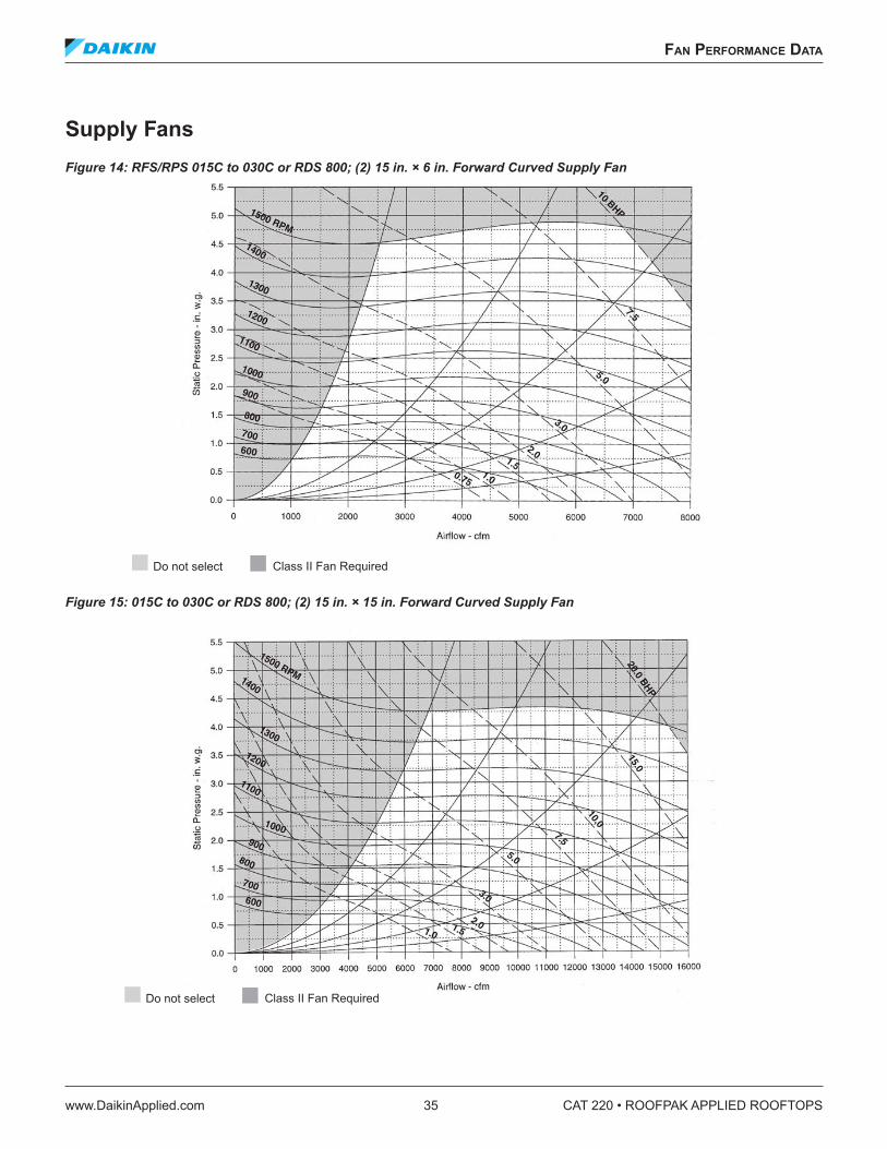
fan performanCe daTa
www.DaikinApplied.com 35 CAT 220 • ROOFPAK APPLIED ROOFTOPS
fan performanCe daTa
Supply FansFigure 14: RFS/RPS 015C to 030C or RDS 800; (2) 15 in. × 6 in. Forward Curved Supply Fan
Figure 15: 015C to 030C or RDS 800; (2) 15 in. × 15 in. Forward Curved Supply Fan
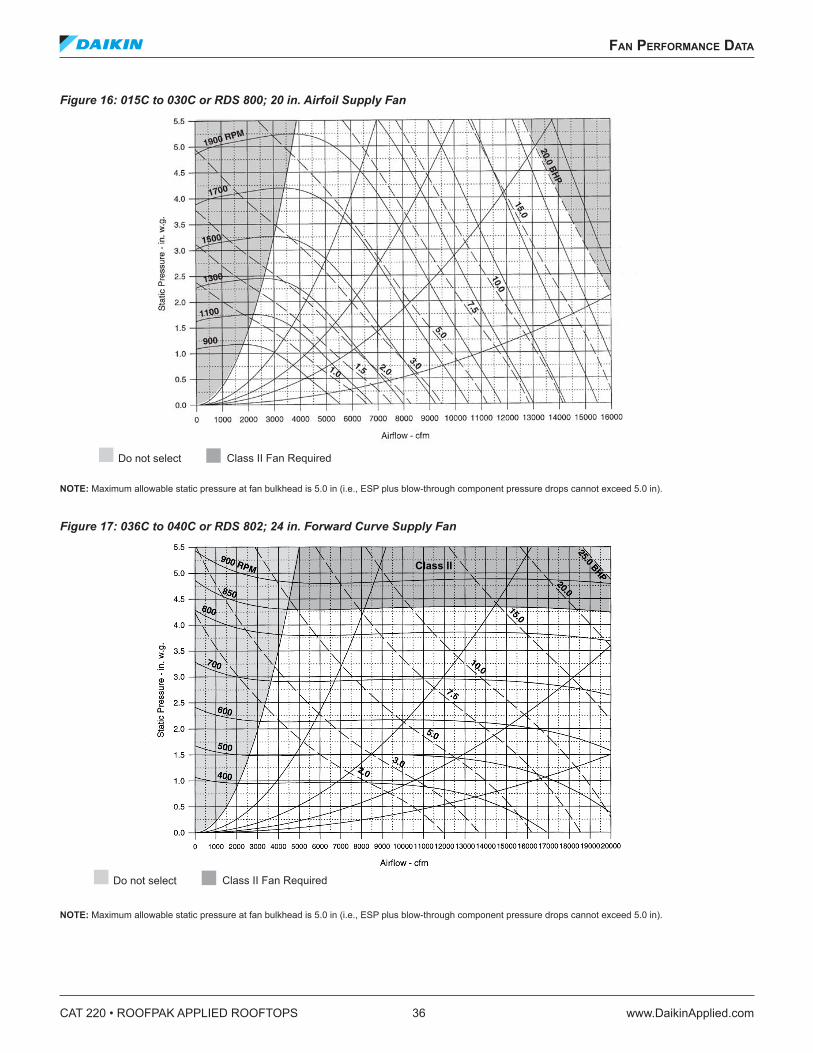
CAT 220 • ROOFPAK APPLIED ROOFTOPS 36 www.DaikinApplied.com
fan performanCe daTa
Figure 16: 015C to 030C or RDS 800; 20 in. Airfoil Supply Fan
NOTE: Maximum allowable static pressure at fan bulkhead is 5.0 in (i.e., ESP plus blow-through component pressure drops cannot exceed 5.0 in).
Figure 17: 036C to 040C or RDS 802; 24 in. Forward Curve Supply Fan
NOTE: Maximum allowable static pressure at fan bulkhead is 5.0 in (i.e., ESP plus blow-through component pressure drops cannot exceed 5.0 in).
Class II
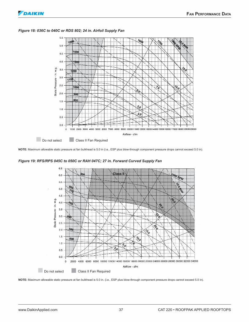
fan performanCe daTa
www.DaikinApplied.com 37 CAT 220 • ROOFPAK APPLIED ROOFTOPS
Figure 18: 036C to 040C or RDS 802; 24 in. Airfoil Supply Fan
NOTE: Maximum allowable static pressure at fan bulkhead is 5.0 in (i.e., ESP plus blow-through component pressure drops cannot exceed 5.0 in).
Figure 19: RFS/RPS 045C to 050C or RAH 047C; 27 in. Forward Curved Supply Fan
NOTE: Maximum allowable static pressure at fan bulkhead is 5.0 in. (i.e., ESP plus blow-through component pressure drops cannot exceed 5.0 in).
Class II
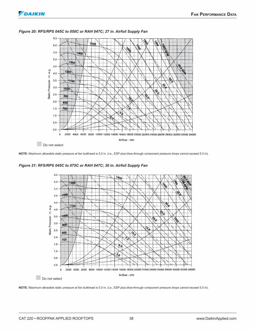
CAT 220 • ROOFPAK APPLIED ROOFTOPS 38 www.DaikinApplied.com
fan performanCe daTa
Figure 20: RFS/RPS 045C to 050C or RAH 047C; 27 in. Airfoil Supply Fan
NOTE: Maximum allowable static pressure at fan bulkhead is 5.0 in. (i.e., ESP plus blow-through component pressure drops cannot exceed 5.0 in).
Figure 21: RFS/RPS 045C to 075C or RAH 047C; 30 in. Airfoil Supply Fan
NOTE: Maximum allowable static pressure at fan bulkhead is 5.0 in. (i.e., ESP plus blow-through component pressure drops cannot exceed 5.0 in).
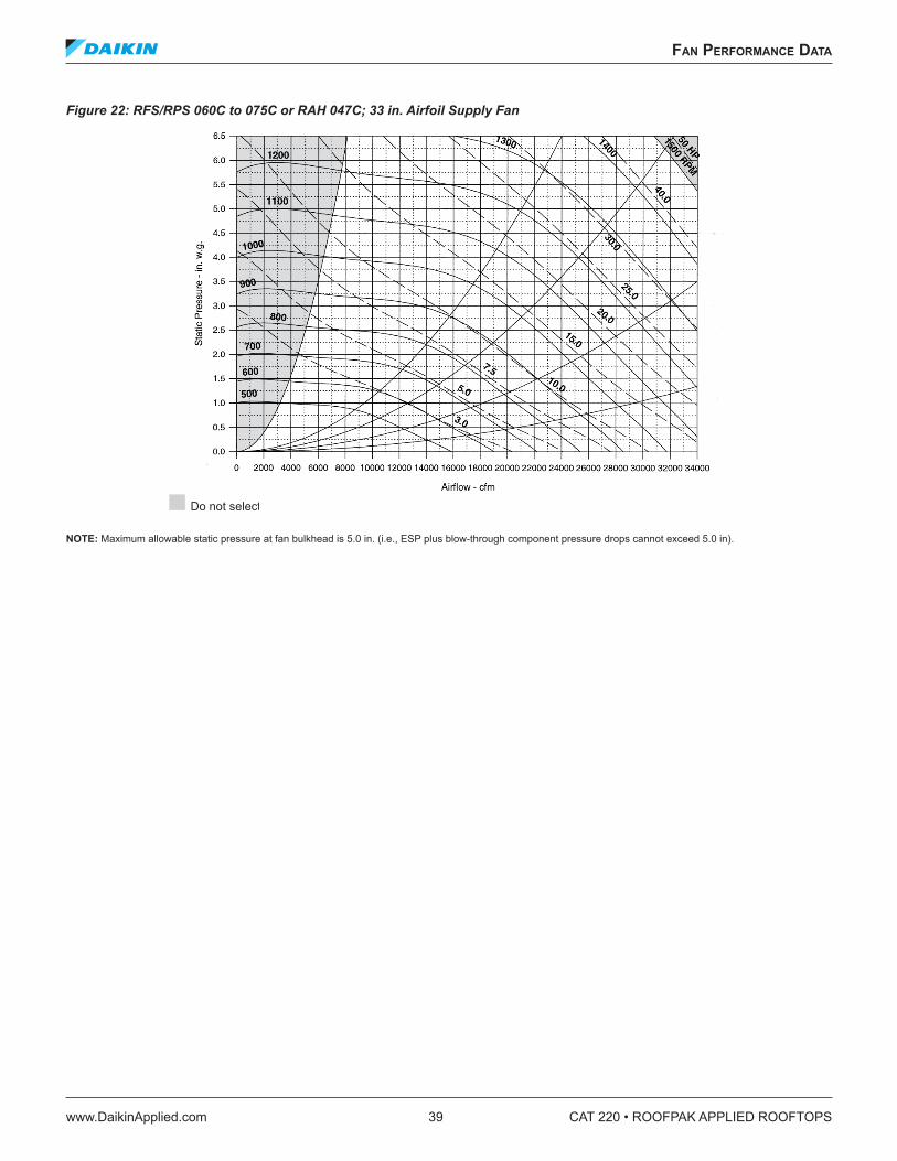
fan performanCe daTa
www.DaikinApplied.com 39 CAT 220 • ROOFPAK APPLIED ROOFTOPS
Figure 22: RFS/RPS 060C to 075C or RAH 047C; 33 in. Airfoil Supply Fan
NOTE: Maximum allowable static pressure at fan bulkhead is 5.0 in. (i.e., ESP plus blow-through component pressure drops cannot exceed 5.0 in).
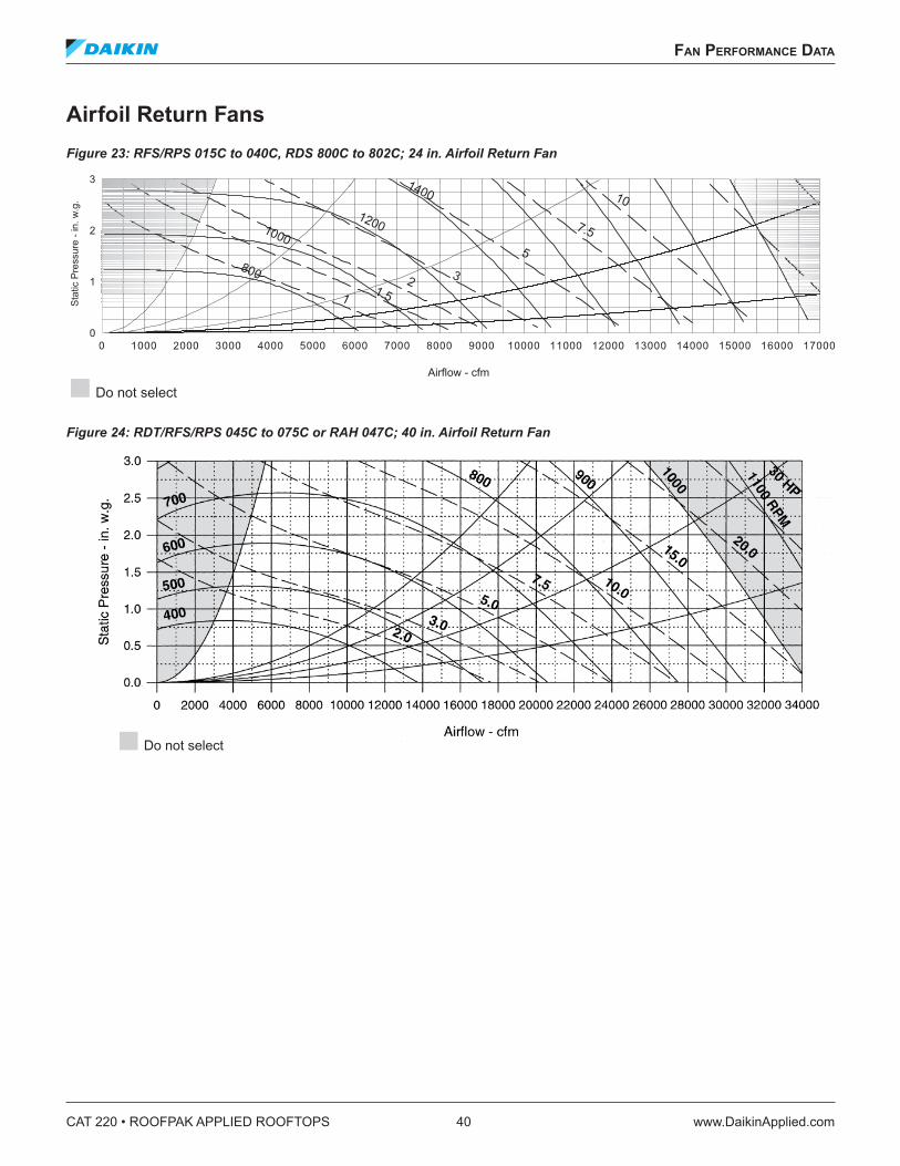
CAT 220 • ROOFPAK APPLIED ROOFTOPS 40 www.DaikinApplied.com
fan performanCe daTa
Airfoil Return FansFigure 23: RFS/RPS 015C to 040C, RDS 800C to 802C; 24 in. Airfoil Return Fan
Figure 24: RDT/RFS/RPS 045C to 075C or RAH 047C; 40 in. Airfoil Return Fan
w.ni-erusser
Pcitat
S.g.
800
1000
1200
1400
1 1.52 3
5
7.5
10
Airflow - cfm
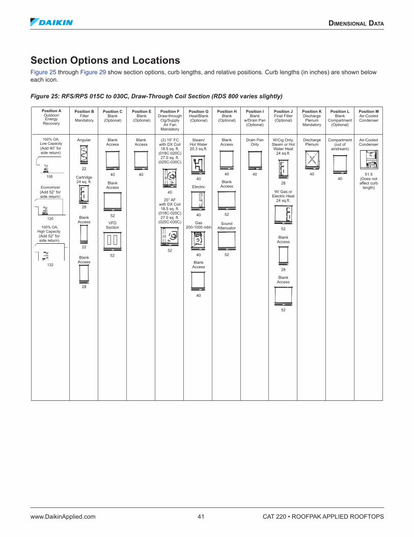
dImensIonal daTa
www.DaikinApplied.com 41 CAT 220 • ROOFPAK APPLIED ROOFTOPS
dImensIonal daTa
Section Options and Locations Figure 25 through Figure 29 show section options, curb lengths, and relative positions. Curb lengths (in inches) are shown below each icon.
Figure 25: RFS/RPS 015C to 030C, Draw-Through Coil Section (RDS 800 varies slightly)
100% OA,
High Capacity
120
EnergyRecovery
(Add 52” forside return)
108
Economizer(Add 52” forside return)
100% OA,
Low Capacity(Add 40” forside return)
132
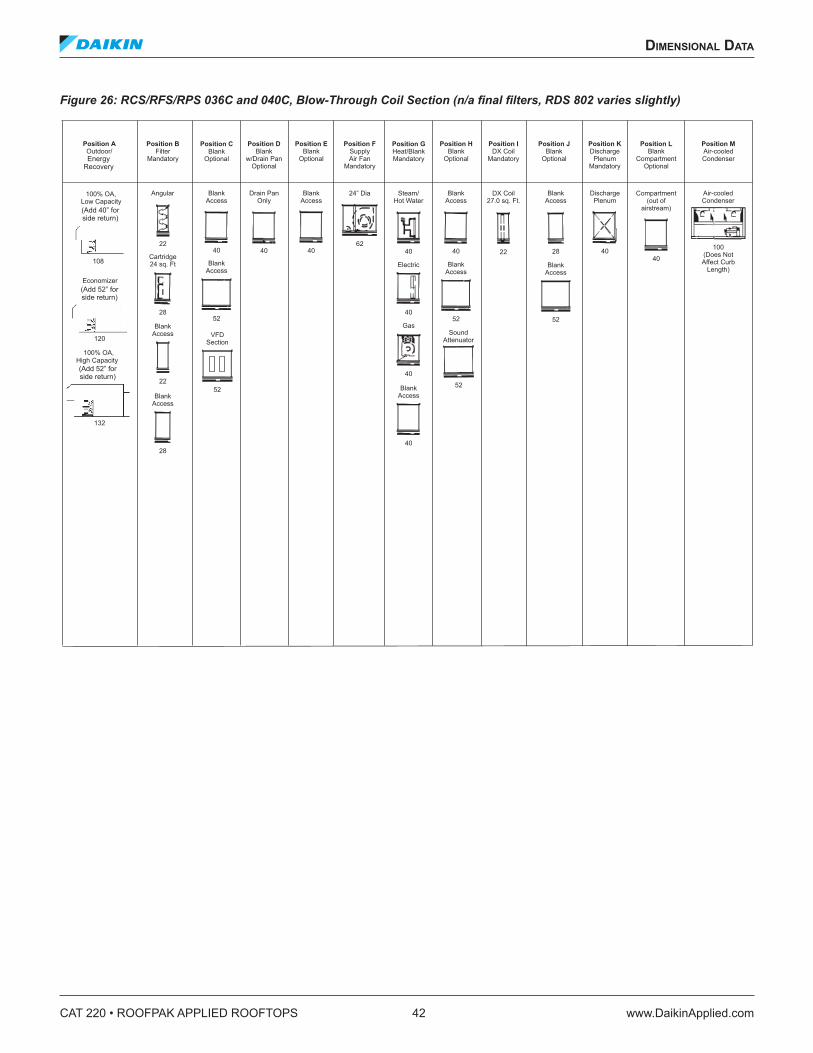
CAT 220 • ROOFPAK APPLIED ROOFTOPS 42 www.DaikinApplied.com
dImensIonal daTa
Figure 26: RCS/RFS/RPS 036C and 040C, Blow-Through Coil Section (n/a final filters, RDS 802 varies slightly)
100% OA,
High Capacity
120
(Add 52” forside return)
108
Economizer(Add 52” forside return)
100% OA,
Low Capacity(Add 40” forside return)
132
EnergyRecovery
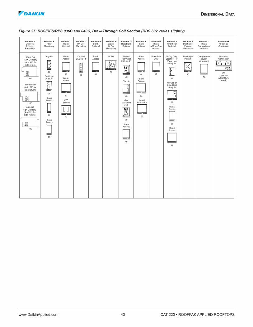
dImensIonal daTa
www.DaikinApplied.com 43 CAT 220 • ROOFPAK APPLIED ROOFTOPS
Figure 27: RCS/RFS/RPS 036C and 040C, Draw-Through Coil Section (RDS 802 varies slightly)
100% OA,
High Capacity
120
(Add 52” forside return)
108
Economizer(Add 52” forside return)
100% OA,
Low Capacity(Add 40” forside return)
132
EnergyRecovery
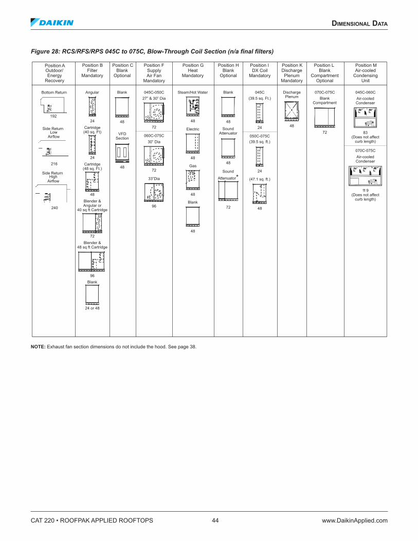
CAT 220 • ROOFPAK APPLIED ROOFTOPS 44 www.DaikinApplied.com
dImensIonal daTa
Figure 28: RCS/RFS/RPS 045C to 075C, Blow-Through Coil Section (n/a final filters)
NOTE: Exhaust fan section dimensions do not include the hood. See page 38.
Outdoor/
48
Angular
24
Cartridge(40 sq. Ft)
24
Cartridge(48 sq. Ft.)
Blank
24 or 48
FilterMandatory
Blank
48
BlankOptional
045C-050C27” & 30” Dia
72
060C-075C30” Dia
72
33”Dia
96
SupplyAir Fan
Mandatory
Steam/Hot Water
48
Electric
Gas
48
Blank
48
48
HeatMandatory
48
Blank
BlankOptional
045C(39.5 sq. Ft.)
24
050C-075C(39.5 sq. ft.)
24
(47.1 sq. ft.)
48
DX CoilMandatory
DischargePlenum
48
DischargePlenum
Mandatory
070C-075CBlank
Compartment
72
BlankCompartment
Optional
Air-cooledCondenser
045C-060C
11 9(Does not affect
curb length)
070C-075C
Air-cooledCondenser
83(Does not affect
curb length)
Air-cooledCondensing
Unit
Blender &Angular or
40 sq ft Cartridge
72
Blender &48 sq ft Cartridge
96
48
SoundAttenuator
Sound
Attenuator*
72
48
VFDSection
Position A Position B Position C Position F Position G Position H Position I Position K Position L Position M
Bottom Return
192
Side Return
216
EnergyRecovery
LowAirflow
240
Side ReturnHigh
Airflow
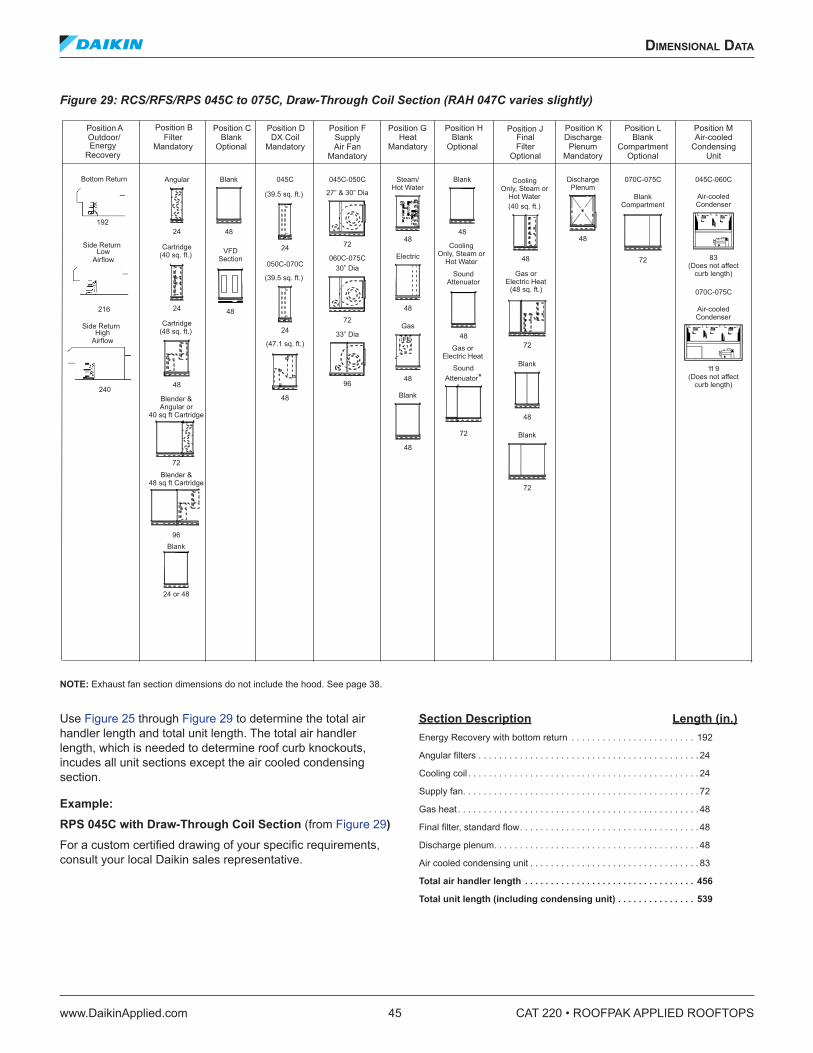
dImensIonal daTa
www.DaikinApplied.com 45 CAT 220 • ROOFPAK APPLIED ROOFTOPS
Figure 29: RCS/RFS/RPS 045C to 075C, Draw-Through Coil Section (RAH 047C varies slightly)
NOTE: Exhaust fan section dimensions do not include the hood. See page 38.
Use Figure 25 through Figure 29 to determine the total air handler length and total unit length. The total air handler length, which is needed to determine roof curb knockouts, incudes all unit sections except the air cooled condensing section.
Example: RPS 045C with Draw-Through Coil Section (from Figure 29) For a custom certified drawing of your specific requirements, consult your local Daikin sales representative.
Section Description Length (in .) Energy Recovery with bottom return . . . . . . . . . . . . . . . . . . . . . . . . 192
Angular filters . . . . . . . . . . . . . . . . . . . . . . . . . . . . . . . . . . . . . . . . . . . 24
Cooling coil . . . . . . . . . . . . . . . . . . . . . . . . . . . . . . . . . . . . . . . . . . . . . 24
Supply fan. . . . . . . . . . . . . . . . . . . . . . . . . . . . . . . . . . . . . . . . . . . . . . 72
Gas heat . . . . . . . . . . . . . . . . . . . . . . . . . . . . . . . . . . . . . . . . . . . . . . . 48
Final filter, standard flow. . . . . . . . . . . . . . . . . . . . . . . . . . . . . . . . . . . 48
Discharge plenum. . . . . . . . . . . . . . . . . . . . . . . . . . . . . . . . . . . . . . . . 48
Air cooled condensing unit . . . . . . . . . . . . . . . . . . . . . . . . . . . . . . . . . 83
Total air handler length . . . . . . . . . . . . . . . . . . . . . . . . . . . . . . . . . 456
Total unit length (including condensing unit) . . . . . . . . . . . . . . . 539
045C-050C
27” & 30” Dia
72
060C-075C30” Dia
72
33” Dia
96
SupplyAir Fan
Mandatory
045C-060C
Air-cooledCondenser
11 9(Does not affect
curb length)
070C-075C
Air-cooledCondenser
83(Does not affect
curb length)
Air-cooledCondensing
Unit
72
070C-075C
BlankCompartment
BlankCompartment
Optional
48
DischargePlenum
DischargePlenum
Mandatory
Blank
48
BlankOptional
48
Blank
BlankOptional
48
045C
(39.5 sq. ft.)
24
050C-070C
(39.5 sq. ft.)
24
(47.1 sq. ft.)
DX CoilMandatory
Outdoor/
Steam/Hot Water
48
Electric
Gas
48
Blank
48
48
HeatMandatory
48
(40 sq. ft.)
48
(48 sq. ft.)
72
Blank
Blank
72
FinalFilter
Optional
48
SoundAttenuator
Gas orElectric Heat
Gas orElectric Heat
CoolingOnly, Steam or
Hot Water
CoolingOnly, Steam or
Hot Water
SoundAttenuator*
72
48
VFDSection
Angular
24
Cartridge(40 sq. ft.)
24
Cartridge(48 sq. ft.)
48
FilterMandatory
Blank
24 or 48
Blender &Angular or
40 sq ft Cartridge
72
Blender &48 sq ft Cartridge
96
Position A Position B Position C Position D Position F Position G Position H Position J Position K Position L Position M
EnergyRecovery
Bottom Return
192
Side Return
216
LowAirflow
240
Side ReturnHigh
Airflow
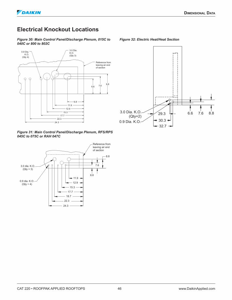
CAT 220 • ROOFPAK APPLIED ROOFTOPS 46 www.DaikinApplied.com
dImensIonal daTa
Electrical Knockout LocationsFigure 30: Main Control Panel/Discharge Plenum, 015C to 040C or 800 to 802C
Figure 31: Main Control Panel/Discharge Plenum, RFS/RPS 045C to 075C or RAH 047C
Figure 32: Electric Heat/Heat Section
8.8
0.9 Dia. K.O.
(Qty 4)
3.0 Dia. K.O. (Qty 3)
6.8
7.6 6.6
Reference from leaving air end of section
11.9 12.9
22.3 17.7
15.3
24.3
17.7
3.0 dia. K.O.(Qty = 3)
0.9 dia. K.O.(Qty = 4)
11.9
12.9
15.3
6.6
18.7
22.3
24.3
7.6
8.8
Reference fromleaving air end of section
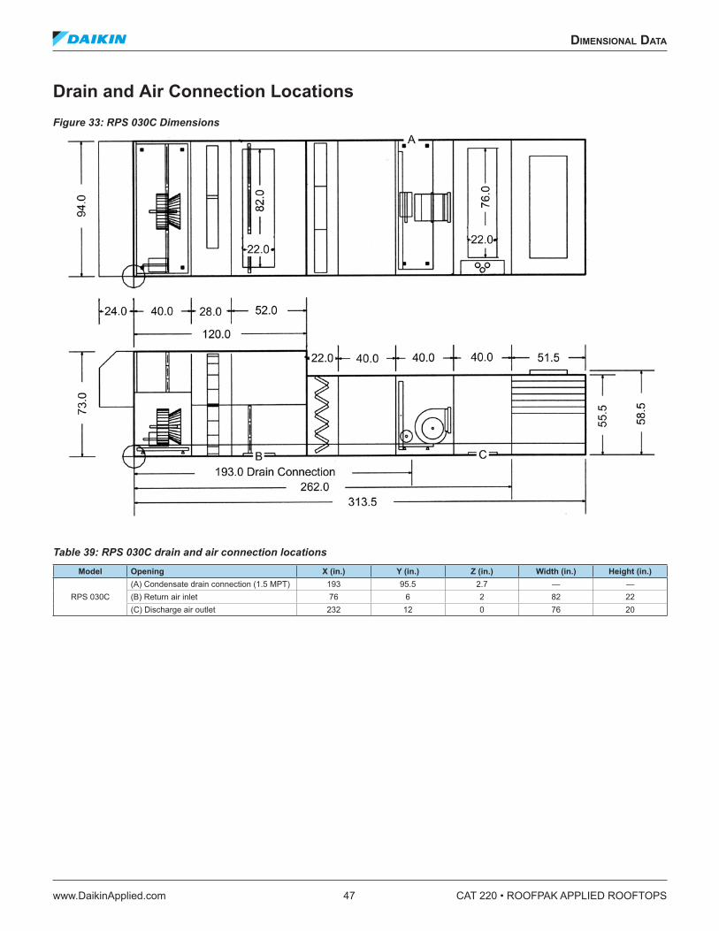
dImensIonal daTa
www.DaikinApplied.com 47 CAT 220 • ROOFPAK APPLIED ROOFTOPS
Drain and Air Connection Locations Figure 33: RPS 030C Dimensions
Table 39: RPS 030C drain and air connection locations Model Opening X (in .) Y (in .) Z (in .) Width (in .) Height (in .)
RPS 030C(A) Condensate drain connection (1.5 MPT) 193 95.5 2.7 — —(B) Return air inlet 76 6 2 82 22(C) Discharge air outlet 232 12 0 76 20
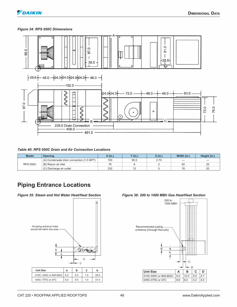
CAT 220 • ROOFPAK APPLIED ROOFTOPS 48 www.DaikinApplied.com
dImensIonal daTa
Figure 34: RPS 050C Dimensions
Table 40: RPS 050C Drain and Air Connection Locations Model Opening X (in .) Y (in .) Z (in .) Width (in .) Height (in .)
RPS 050C(A) Condensate drain connection (1.5 MPT) 193 95.5 2.70 — —(B) Return air inlet 76 6 2 82 22(C) Discharge air outlet 232 12 0 76 20
Piping Entrance Locations Figure 35: Steam and Hot Water Heat/Heat Section Figure 36: 200 to 1400 MBh Gas Heat/Heat Section
D
C
B
A
A B C D
015C–040C or 800-802C 6.0 6.5 1.0 29.0
045C C or 47C 6.0 9.0 1.0 37.0
All piping entrance holesshould fall within this area
Unit Size
–075
Recommended p ipingentrance (through the curb)
BA
C
D
200 to1000 MBH
015C-040C 6.0 12.0 5.0 2.7045C-075C 8.6 6.0 4.2 4.0
or 800-802Cor 47C
Unit Size A B C D
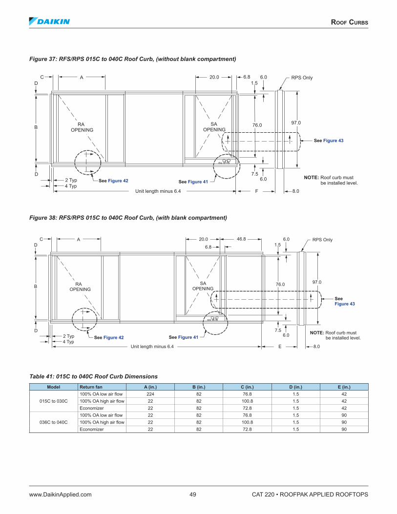
roof Curbs
www.DaikinApplied.com 49 CAT 220 • ROOFPAK APPLIED ROOFTOPS
roof Curbs
Figure 37: RFS/RPS 015C to 040C Roof Curb, (without blank compartment)
Figure 38: RFS/RPS 015C to 040C Roof Curb, (with blank compartment)
Table 41: 015C to 040C Roof Curb Dimensions Model Return fan A (in .) B (in .) C (in .) D (in .) E (in .)
015C to 030C100% OA low air flow 224 82 76.8 1.5 42100% OA high air flow 22 82 100.8 1.5 42Economizer 22 82 72.8 1.5 42
036C to 040C100% OA low air flow 22 82 76.8 1.5 90100% OA high air flow 22 82 100.8 1.5 90Economizer 22 82 72.8 1.5 90
CD
D2 Typ4 Typ
B
A 20.0 6.81.5
6.0
76.0 97.0
RPS Only
SAOPENING
7.56.0
8.0FUnit length minus 6.4
RAOPENING
NOTE: Roof curb must be installed level.See Figure 42 See Figure 41
See Figure 43
CD
D2 Typ4 Typ
B
A 20.0 46.8
6.8 1.56.0
76.0 97.0
RPS Only
SAOPENING
7.56.0
8.0EUnit length minus 6.4
RAOPENING
NOTE: Roof curb must be installed level.See Figure 42 See Figure 41
See Figure 43
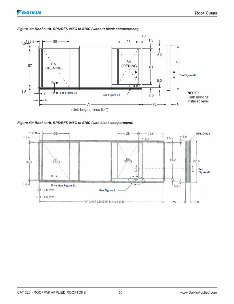
CAT 220 • ROOFPAK APPLIED ROOFTOPS 50 www.DaikinApplied.com
roof Curbs
Figure 39: Roof curb, RPS/RFS 045C to 075C (without blank compartment)
Figure 40: Roof curb, RPS/RFS 045C to 075C (with blank compartment)
87 RAOPENING
381.5
B
B2
4A 75
81
28
100
8
7.5
5.0
5.0
AA
SAOPENING
(Unit length minus 6.4")
NOTE:Curb must beinstalled level.
1.5
1.5138.86.8
See Figure 42See Figure 41
SeeFigure 43
See Figure 42
See Figure 41
See Figure 43
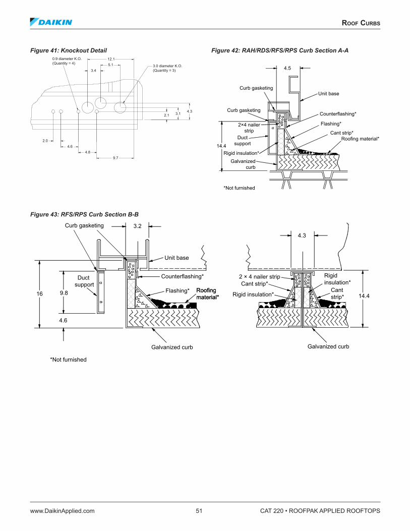
roof Curbs
www.DaikinApplied.com 51 CAT 220 • ROOFPAK APPLIED ROOFTOPS
Figure 41: Knockout Detail Figure 42: RAH/RDS/RFS/RPS Curb Section A-A
Figure 43: RFS/RPS Curb Section B-B
5.112.1
3.4
4.84.6
2.0
9.7
2.1 3.1 4.3
0.9 diameter K.O. (Quantity = 4)
3.0 diameter K.O. (Quantity = 3) 4.5
14.4
Curb gasketing
2×4 nailerstrip
Ductsupport
Counterflashing*
Galvanizedcurb
Roofing material*Cant strip*
Flashing*
Unit base
*Not furnished
Curb gasketing
Rigid insulation*
*Not furnished
9.816
4.6
3.24.3
2 × 4 nailer stripCant strip*
14.4
Galvanized curb
Roofingmaterial*Roofingmaterial*
Flashing*
Unit base
Duct support
Curb gasketing
Galvanized curb
Counterflashing*
Rigid insulation*
Rigidinsulation*
Cantstrip*
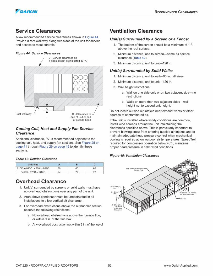
CAT 220 • ROOFPAK APPLIED ROOFTOPS 52 www.DaikinApplied.com
reCommended ClearanCes
reCommended ClearanCes
Service ClearanceAllow recommended service clearances shown in Figure 44. Provide a roof walkway along two sides of the unit for service and access to most controls.
Figure 44: Service Clearances
Cooling Coil, Heat and Supply Fan Service Clearance Additional clearance, “A” is recommended adjacent to the cooling coil, heat, and supply fan sections. See Figure 25 on page 41 through Figure 29 on page 45 to identify these sections.
Table 42: Service Clearance Unit Size A B C
015C to 040C or 800 to 802C 30 60 60045C to 075C or 047C 24 72 72
Overhead Clearance1. Unit(s) surrounded by screens or solid walls must have
no overhead obstructions over any part of the unit.
2. Area above condenser must be unobstructed in all installations to allow vertical air discharge.
3. For overhead obstructions above the air handler section, observe the following restrictions:
a. No overhead obstructions above the furnace flue, or within 9 in. of the flue box.
b. Any overhead obstruction not within 2 in. of the top of
Ventilation ClearanceUnit(s) Surrounded by a Screen or a Fence:
1. The bottom of the screen should be a minimum of 1 ft. above the roof surface.
2. Minimum distance, unit to screen—same as service clearance (Table 42).
3. Minimum distance, unit to unit—120 in.
Unit(s) Surrounded by Solid Walls: 1. Minimum distance, unit to wall—96 in., all sizes
2. Minimum distance, unit to unit—120 in.
3. Wall height restrictions:
a. Wall on one side only or on two adjacent side—no restrictions.
b. Walls on more than two adjacent sides—wall height not to exceed unit height.
Do not locate outside air intakes near exhaust vents or other sources of contaminated air.
If the unit is installed where windy conditions are common, install wind screens around the unit, maintaining the clearances specified above. This is particularly important to prevent blowing snow from entering outside air intakes and to maintain adequate head pressure control when mechanical cooling is required at low outdoor air temperatures. SpeedTrol, required for compressor operation below 45°F, maintains proper head pressure in calm wind conditions.
Figure 45: Ventilation Clearances
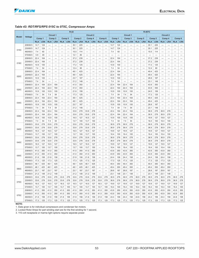
eleCTrICal daTa
www.DaikinApplied.com 53 CAT 220 • ROOFPAK APPLIED ROOFTOPS
eleCTrICal daTa
Table 43: RDT/RFS/RPS 015C to 075C, Compressor Amps
Model Voltage
R-22 R-407CCircuit 1 Circuit 2 Circuit 1 Circuit 2
Comp 1 Comp 3 Comp 5 Comp 2 Comp 4 Comp 6 Comp 1 Comp 3 Comp 5 Comp 2 Comp 4 Comp 6RLA LRA RLA LRA RLA LRA RLA LRA RLA LRA RLA LRA RLA LRA RLA LRA RLA LRA RLA LRA RLA LRA RLA LRA
015C
208/60/3 14.7 124 — — — — 30.1 225 — — — — 14.7 124 — — — — 30.1 225 — — — —
230/60/3 14.7 124 — — — — 30.1 225 — — — — 14.7 124 — — — — 30.1 225 — — — —
460/60/3 7.4 60 — — — — 15.5 114 — — — — 7.4 60 — — — — 15.5 114 — — — —
575/60/3 5.9 49 — — — — 12.1 80 — — — — — — — — — — — — — — — —
018C
208/60/3 22.4 164 — — — — 37.2 239 — — — — 22.4 164 — — — — 37.2 239 — — — —
230/60/3 22.4 164 — — — — 37.2 239 — — — — 22.4 164 — — — — 37.2 239 — — — —
460/60/3 10.9 100 — — — — 17.2 125 — — — — 10.9 100 — — — — 17.2 125 — — — —
575/60/3 7.4 54 — — — — 12.4 80 — — — — 7.4 54 — — — — 12.4 80 — — — —
020C
208/60/3 22.4 164 — — — — 48.1 425 — — — — 22.4 164 — — — — 49.4 425 — — — —
230/60/3 22.4 164 — — — — 48.1 425 — — — — 22.4 164 — — — — 49.4 425 — — — —
460/60/3 10.9 100 — — — — 23.7 187 — — — — 10.9 100 — — — — 28.8 187 — — — —
575/60/3 7.4 54 — — — — 21.2 148 — — — — 7.4 54 — — — — 23.1 148 — — — —
025C
208/60/3 22.4 164 22.4 164 — — 41.0 350 — — — — 22.4 164 22.4 164 — — 43.9 350 — —
230/60/3 22.4 164 22.4 164 — — 41.0 350 — — — — 22.4 164 22.4 164 — — 43.9 350 — —
460/60/3 10.9 100 10.9 100 — — 21.8 158 — — — — 10.9 100 10.9 100 — — 24.5 158 — —
575/60/3 7.4 54 7.4 54 — — 17.3 125 — — — — 7.4 54 7.4 54 — — 17.3 125 — —
030C
208/60/3 22.4 164 22.4 164 — — 48.1 425 — — — — 22.4 164 22.4 164 — — 49.4 425 — — — —
230/60/3 22.4 164 22.4 164 — — 48.1 425 — — — — 22.4 164 22.4 164 — — 49.4 425 — — — —
460/60/3 10.9 100 10.9 100 — — 23.7 187 — — — — 10.9 100 10.9 100 — — 28.8 187 — — — —
575/60/3 7.4 54 7.4 54 — — 21.2 148 — — — — 7.4 54 7.4 54 — — 23.1 148 — — — —
036C
208/60/3 22.4 164 22.4 164 — — 33.6 278 33.6 278 — — 22.4 164 22.4 164 — — 36.9 278 36.9 278 — —
230/60/3 22.4 164 22.4 164 — — 33.6 278 33.6 278 — — 22.4 164 22.4 164 — — 36.9 278 36.9 278 — —
460/60/3 10.9 100 10.9 100 — — 16.5 127 16.5 127 — — 10.9 100 10.9 100 — — 19.9 127 19.9 127 — —
575/60/3 7.4 54 7.4 54 — — 13.7 100 13.7 100 — — 7.4 54 7.4 54 — — 16.4 100 16.4 100 — —
040C
208/60/3 33.6 278 33.6 278 — — 33.6 278 33.6 278 — — 36.9 278 36.9 278 — — 36.9 278 36.9 278 — —
230/60/3 33.6 278 33.6 278 — — 33.6 278 33.6 278 — — 36.9 278 36.9 278 — — 36.9 278 36.9 278 — —
460/60/3 16.5 127 16.5 127 — — 16.5 127 16.5 127 — — 19.9 127 19.9 127 — — 19.9 127 19.9 127 — —
575/60/3 13.7 100 13.7 100 — — 13.7 100 13.7 100 — — 16.4 100 16.4 100 — — 16.4 100 16.4 100 — —
045C
208/60/3 33.6 278 33.6 278 — — 33.6 278 33.6 278 — — 36.9 278 36.9 278 — — 36.9 278 36.9 278 — —
230/60/3 33.6 278 33.6 278 — — 33.6 278 33.6 278 — — 36.9 278 36.9 278 — — 36.9 278 36.9 278 — —
460/60/3 16.5 127 16.5 127 — — 16.5 127 16.5 127 — — 19.9 127 19.9 127 — — 19.9 127 19.9 127 — —
575/60/3 13.7 100 13.7 100 — — 13.7 100 13.7 100 — — 16.4 100 16.4 100 — — 16.4 100 16.4 100 — —
050C
208/60/3 41.0 350 41.0 350 — — 41.0 350 41.0 350 — — 43.9 350 43.9 350 — — 43.9 350 43.9 350 — —
230/60/3 41.0 350 41.0 350 — — 41.0 350 41.0 350 — — 43.9 350 43.9 350 — — 43.9 350 43.9 350 — —
460/60/3 21.8 158 21.8 158 — — 21.8 158 21.8 158 — — 24.4 158 24.4 158 — — 24.4 158 24.4 158 — —
575/60/3 17.3 125 17.3 125 — — 17.3 125 17.3 125 — — 17.3 125 17.3 125 — — 17.3 125 17.3 125 — —
060C
208/60/3 48.1 425 48.1 425 — — 48.1 425 48.1 425 — — 49.4 350 49.4 350 — — 49.4 350 49.4 350 — —
230/60/3 48.1 425 48.1 425 — — 48.1 425 48.1 425 — — 49.4 350 49.4 350 — — 49.4 350 49.4 350 — —
460/60/3 23.7 187 23.7 187 — — 23.7 187 23.7 187 — — 28.8 187 28.8 187 — — 28.8 187 28.8 187 — —
575/60/3 21.2 148 21.2 148 — — 21.2 148 21.2 148 — — 23.1 148 23.1 148 — — 23.1 148 23.1 148 — —
070C
208/60/3 33.6 278 33.6 278 33.6 278 33.6 278 33.6 278 33.6 278 36.9 278 36.9 278 36.9 278 36.9 278 36.9 278 36.9 278
230/60/3 33.6 278 33.6 278 33.6 278 33.6 278 33.6 278 33.6 278 36.9 278 36.9 278 36.9 278 36.9 278 36.9 278 36.9 278
460/60/3 16.5 127 16.5 127 16.5 127 16.5 127 16.5 127 16.5 127 19.9 127 19.9 127 19.9 127 19.9 127 19.9 127 19.9 127
575/60/3 13.7 100 13.7 100 13.7 100 13.7 100 13.7 100 13.7 100 16.4 100 16.4 100 16.4 100 16.4 100 16.4 100 16.4 100
075C
208/60/3 41.0 350 41.0 350 41.0 350 41.0 350 41.0 350 41.0 350 43.9 350 43.9 350 43.9 350 43.9 350 43.9 350 43.9 350
230/60/3 41.0 350 41.0 350 41.0 350 41.0 350 41.0 350 41.0 350 43.9 350 43.9 350 43.9 350 43.9 350 43.9 350 43.9 350
460/60/3 21.8 158 21.8 158 21.8 158 21.8 158 21.8 158 21.8 158 24.4 158 24.4 158 24.8 158 24.4 158 24.4 158 24.8 158
575/60/3 17.3 125 17.3 125 17.3 125 17.3 125 17.3 125 17.3 125 17.3 125 17.3 125 17.3 125 17.3 125 17.3 125 17.3 125
NOTE:1. Data given is for individual compressors and condenser fan motors.2. Locked Rotor Amps for part winding start are for the first winding for 1 second.3. 115-volt receptacle or marine light options require separate power.
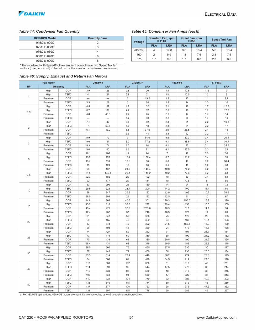
CAT 220 • ROOFPAK APPLIED ROOFTOPS 54 www.DaikinApplied.com
eleCTrICal daTa
Table 44: Condenser Fan Quantity RCS/RPS Model Quantity Fans
015C to 020C 2025C to 030C 3036C to 050C 4060C to 070C 6075C to 090C 8
* Units ordered with SpeedTrol low ambient control have two SpeedTrol fan motors (one per circuit) in lieu of two of the standard condenser fan motors.
Table 45: Condenser Fan Amps (each)
VoltageStandard Fan, rpm
= 1140Quiet Fan, rpm
= 850 SpeedTrol Fan
FLA LRA FLA LRA FLA LRA208/230 4 19.8 3.6 16.4 5.6 16.4
460 2 9.9 1.8 7.6 2.8 7.6575 1.7 9.6 1.7 6.0 2.3 6.0
Table 46: Supply, Exhaust and Return Fan Motors Fan motor 208/60/3 230/60/3 a 460/60/3 575/60/3
HP Efficiency FLA LRA FLA LRA FLA LRA FLA LRA
1
High ODP 3.9 26 2.8 20 1.4 10.5 1.15 9High TEFC 4 27 2.8 21 1.4 10.5 1.2 9
Premium ODP — — 3 19.2 1.5 15 1.1 7.7Premium TEFC 3.3 27 3 28 1.5 14 1.3 10
1.5
High ODP 4.5 39 4.2 32 2.1 16 1.7 12.8High TEFC 6.2 39 4.2 32 2.1 16 1.7 12.8
Premium ODP 4.8 40.3 4.2 25 2.1 14 1.7 14Premium TEFC — — 4.2 40 2.1 20 1.7 16
2
High ODP 7.1 47 5.6 42 2.8 21 2.2 16.8High TEFC 7 50.6 5.6 48 2.8 24 2.2 17
Premium ODP 6.1 43.2 5.8 37.6 2.9 26.5 2.1 15Premium TEFC — — 5.6 44 2.8 22 2.2 17
3
High ODP 9.9 79 9 64.6 4.5 32.3 3.4 26.1High TEFC 9.6 81 8.2 77.2 4.1 38.6 3.4 30.9
Premium ODP 9.3 74 8.2 64 4.1 32 3.1 25.6Premium TEFC 9.4 80 8.2 71 4.1 35.5 3.3 29
5
High ODP 16.1 106 14 94 7 47 5.3 38High TEFC 15.2 126 13.4 102.4 6.7 51.2 5.4 39
Premium ODP 15.7 110 13.6 96 6.8 48 5.2 38.4Premium TEFC 15 124 13 96 6.5 48 5.2 38
7.5
High ODP 25 137 21.6 148.4 10.8 74.2 8.2 49High TEFC 24.8 175.3 20.4 145.2 10.2 72.6 8.2 58
Premium ODP 22.3 185 20 122 10 80 7.4 52Premium TEFC 22 177 20 141 10 70.5 8 56
10
High ODP 33 290 28 180 14 94 11 72High TEFC 29.5 228 28.4 200 14.2 100 11.4 80
Premium ODP 29 247 25.8 192 12.9 106 10.3 76.6Premium TEFC 28.5 209 25 182 12.5 91 10 67
15
High ODP 44.8 368 40.6 301 20.3 150.5 16.2 120High TEFC 43.7 310 38.8 272 19.4 136 15.5 109
Premium ODP 43.4 271 37.8 233.6 18.9 117 14.1 94Premium TEFC 42.4 282 37 246 18.5 123 14 89
20
High ODP 61 342 50 350 25 175 20 135High TEFC 60 465 48 320 24 160 19.1 123
Premium ODP 57 373 49 322 24.5 160.8 18.9 130Premium TEFC 56 403 48 350 24 175 18.8 138
25
High ODP 74 427 62 382 31 191 24.3 151High TEFC 73 416 60 380 30 190 24.2 152
Premium ODP 70 438 61 380 30.5 190 24.2 125Premium TEFC 68.4 431 61 376 30.5 188 22.8 148
30
High ODP 86.5 560 75 460 37.5 230 30 177High TEFC 87 448 72 460 36 230 28.6 184
Premium ODP 83.3 514 72.4 448 36.2 224 29.8 179Premium TEFC 84 566 69 428 34.5 214 27.6 178
40
High ODP 117 660 102 630 51 315 40 251High TEFC 114 590 95 544 47.5 272 38 214
Premium ODP 110 730 96 630 48 315 38 245Premium TEFC 106 734 94 650 47 325 37 213
50
High ODP 140 832 124 770 62 385 49.2 303High TEFC 136 840 118 744 59 372 48 266
Premium ODP 137 877 120 752 60 376 47.5 332Premium TEFC 131 897 118 778 59 389 46 237
a. For 380/50/3 applications, 460/60/3 motors are used. Derate nameplate by 0.85 to obtain actual horsepower.
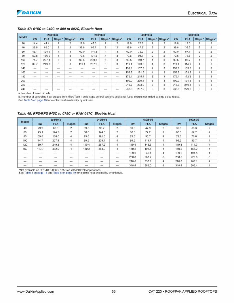
eleCTrICal daTa
www.DaikinApplied.com 55 CAT 220 • ROOFPAK APPLIED ROOFTOPS
Table 47: 015C to 040C or 800 to 802C, Electric Heat
Model208/60/3 240/60/3 480/60/3 600/60/3
kW FLA Steps a Stages b kW FLA Steps a Stages b kW FLA Steps a Stages b kW FLA Steps a Stages b
20 14.4 41.4 2 2 19.8 47.6 2 2 19.8 23.8 2 2 19.8 19.0 2 240 29.9 83.0 2 2 39.8 95.7 2 2 39.8 47.8 2 2 39.8 38.3 2 260 45.1 124.9 4 3 60.0 144.3 4 3 60.0 72.2 2 2 60.0 57.7 2 280 59.8 166.0 4 3 79.6 191.5 4 3 79.6 94.7 2 2 79.6 76.6 2 2
100 74.7 207.4 6 3 99.5 239.3 6 3 99.5 119.7 4 3 99.5 95.7 4 3120 89.7 249.3 6 3 119.4 287.2 6 3 119.4 143.6 4 3 119.4 114.9 4 3140 — — — — — — — — 139.1 167.3 4 3 139.1 133.8 4 3160 — — — — — — — — 159.2 191.5 4 3 159.2 153.2 4 3180 — — — — — — — — 179.1 215.4 6 3 179.1 172.3 6 3200 — — — — — — — — 199.0 239.4 6 3 199.0 191.5 6 3220 — — — — — — — — 218.7 263.0 6 3 218.7 210.4 6 3240 — — — — — — — — 238.8 287.2 6 3 238.8 229.8 6 3
a. Number of fused circuits b. Number of controlled heat stages from MicroTech II solid-state control system; additional fused circuits controlled by time delay relays. See Table 5 on page 18 for electric heat availability by unit size.
Table 48: RFS/RPS 045C to 075C or RAH 047C, Electric Heat
Model208/60/3 240/60/3 480/60/3 600/60/3
kW FLA Stages kW FLA Stages kW FLA Stages kW FLA Stages40 29.9 83.0 2 39.8 95.7 2 39.8 47.9 2 39.8 38.3 260 45.1 124.9 2 60.0 144.3 2 60.0 72.2 2 60.0 57.7 280 59.8 166.0 4 79.6 191.5 4 79.6 95.7 4 79.6 76.6 4
100 74.7 207.4 4 99.5 239.4 4 99.5 119.7 4 99.5 95.7 4120 89.7 249.3 4 119.4 287.2 4 119.4 143.6 4 119.4 114.9 4160 119.7 332.0 4 159.2 383.0 4 159.2 191.5 4 159.2 153.2 4— — — — — — — 199.0 239.4 4 199.0 191.5 4— — — — — — — 238.8 287.2 6 238.8 229.8 6— — — — — — — 278.6 335.1 4 278.6 268.1 4— — — — — — — 318.4 383.0 4 318.4 306.4 4
*Not available on RPS/RFS 808C–135C on 208/240 volt applications. See Table 5 on page 18 and Table 6 on page 19 for electric heat availability by unit size.
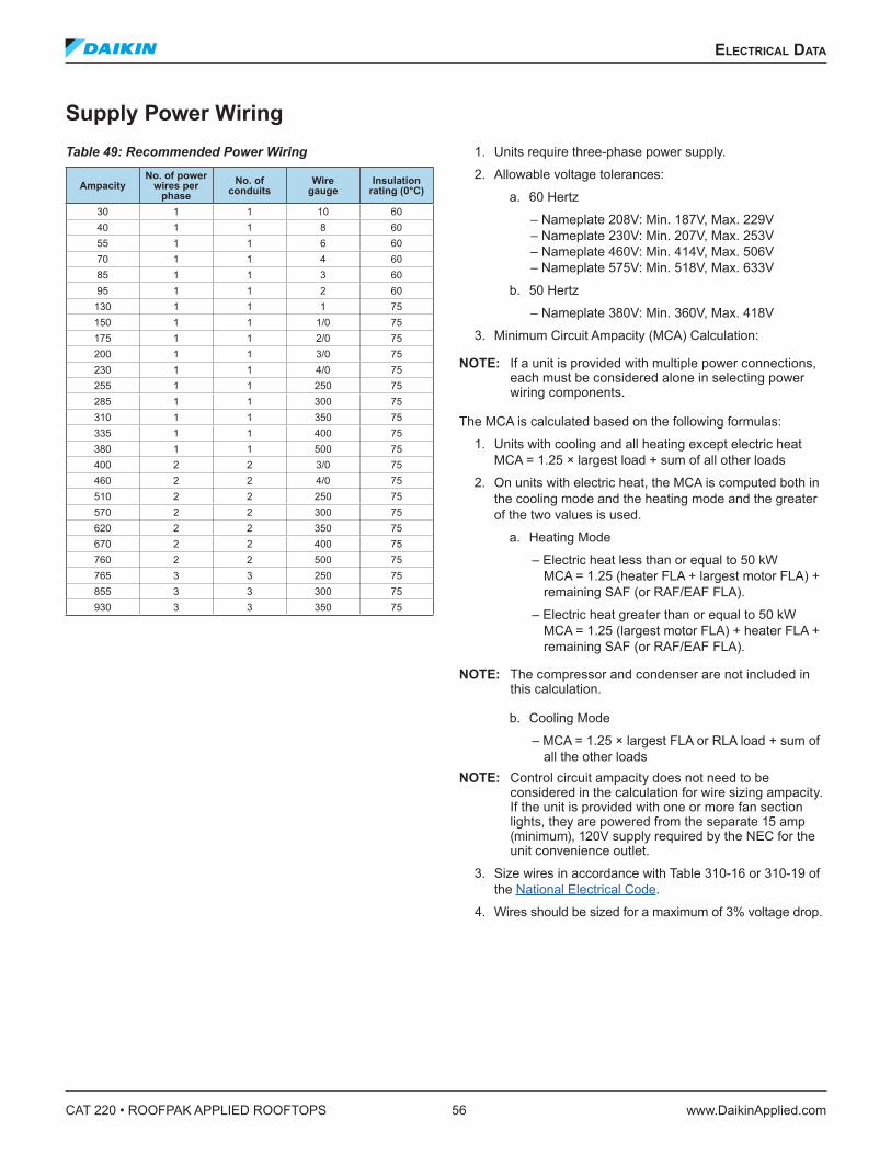
CAT 220 • ROOFPAK APPLIED ROOFTOPS 56 www.DaikinApplied.com
eleCTrICal daTa
Supply Power WiringTable 49: Recommended Power Wiring
AmpacityNo . of power
wires per phase
No . of conduits
Wire gauge
Insulation rating (0°C)
30 1 1 10 6040 1 1 8 6055 1 1 6 6070 1 1 4 6085 1 1 3 6095 1 1 2 60
130 1 1 1 75150 1 1 1/0 75175 1 1 2/0 75200 1 1 3/0 75230 1 1 4/0 75255 1 1 250 75285 1 1 300 75310 1 1 350 75335 1 1 400 75380 1 1 500 75400 2 2 3/0 75460 2 2 4/0 75510 2 2 250 75570 2 2 300 75620 2 2 350 75670 2 2 400 75760 2 2 500 75765 3 3 250 75855 3 3 300 75930 3 3 350 75
1. Units require three-phase power supply.
2. Allowable voltage tolerances:
a. 60 Hertz
– Nameplate 208V: Min. 187V, Max. 229V – Nameplate 230V: Min. 207V, Max. 253V – Nameplate 460V: Min. 414V, Max. 506V – Nameplate 575V: Min. 518V, Max. 633V
b. 50 Hertz
– Nameplate 380V: Min. 360V, Max. 418V
3. Minimum Circuit Ampacity (MCA) Calculation:
NOTE: If a unit is provided with multiple power connections, each must be considered alone in selecting power wiring components.
The MCA is calculated based on the following formulas:
1. Units with cooling and all heating except electric heat MCA = 1.25 × largest load + sum of all other loads
2. On units with electric heat, the MCA is computed both in the cooling mode and the heating mode and the greater of the two values is used.
a. Heating Mode
– Electric heat less than or equal to 50 kW MCA = 1.25 (heater FLA + largest motor FLA) + remaining SAF (or RAF/EAF FLA).
– Electric heat greater than or equal to 50 kW MCA = 1.25 (largest motor FLA) + heater FLA + remaining SAF (or RAF/EAF FLA).
NOTE: The compressor and condenser are not included in this calculation.
b. Cooling Mode
– MCA = 1.25 × largest FLA or RLA load + sum of all the other loads
NOTE: Control circuit ampacity does not need to be considered in the calculation for wire sizing ampacity. If the unit is provided with one or more fan section lights, they are powered from the separate 15 amp (minimum), 120V supply required by the NEC for the unit convenience outlet.
3. Size wires in accordance with Table 310-16 or 310-19 of the National Electrical Code.
4. Wires should be sized for a maximum of 3% voltage drop.
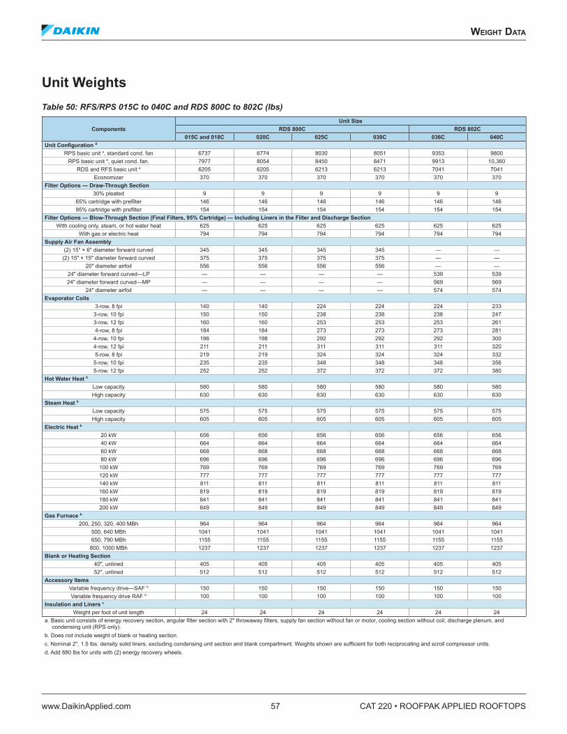
WeIghT daTa
www.DaikinApplied.com 57 CAT 220 • ROOFPAK APPLIED ROOFTOPS
WeIghT daTa
Unit WeightsTable 50: RFS/RPS 015C to 040C and RDS 800C to 802C (lbs)
ComponentsUnit Size
RDS 800C RDS 802C015C and 018C 020C 025C 030C 036C 040C
Unit Configuration d
RPS basic unit a, standard cond. fan 6737 6774 8030 8051 9353 9800RPS basic unit a, quiet cond. fan. 7977 8054 8450 8471 9913 10,360
RDS and RFS basic unit a 6205 6205 6213 6213 7041 7041Economizer 370 370 370 370 370 370
Filter Options — Draw-Through Section30% pleated 9 9 9 9 9 9
65% cartridge with prefilter 146 146 146 146 146 14695% cartridge with prefilter 154 154 154 154 154 154
Filter Options — Blow-Through Section (Final Filters, 95% Cartridge) — Including Liners in the Filter and Discharge SectionWith cooling only, steam, or hot water heat 625 625 625 625 625 625
With gas or electric heat 794 794 794 794 794 794Supply Air Fan Assembly
(2) 15" × 6" diameter forward curved 345 345 345 345 — —(2) 15" × 15" diameter forward curved 375 375 375 375 — —
20" diameter airfoil 556 556 556 556 — —24" diameter forward curved—LP — — — — 539 53924" diameter forward curved—MP — — — — 569 569
24" diameter airfoil — — — — 574 574Evaporator Coils
3-row, 8 fpi 140 140 224 224 224 2333-row, 10 fpi 150 150 238 238 238 2473-row, 12 fpi 160 160 253 253 253 2614-row, 8 fpi 184 184 273 273 273 281
4-row, 10 fpi 198 198 292 292 292 3004-row, 12 fpi 211 211 311 311 311 3205-row, 8 fpi 219 219 324 324 324 332
5-row, 10 fpi 235 235 348 348 348 3565-row, 12 fpi 252 252 372 372 372 380
Hot Water Heat b
Low capacity 580 580 580 580 580 580High capacity 630 630 630 630 630 630
Steam Heat b
Low capacity 575 575 575 575 575 575High capacity 605 605 605 605 605 605
Electric Heat b
20 kW 656 656 656 656 656 65640 kW 664 664 664 664 664 66460 kW 668 668 668 668 668 66880 kW 696 696 696 696 696 696
100 kW 769 769 769 769 769 769120 kW 777 777 777 777 777 777140 kW 811 811 811 811 811 811160 kW 819 819 819 819 819 819180 kW 841 841 841 841 841 841200 kW 849 849 849 849 849 849
Gas Furnace b
200, 250, 320, 400 MBh 964 964 964 964 964 964500, 640 MBh 1041 1041 1041 1041 1041 1041650, 790 MBh 1155 1155 1155 1155 1155 1155
800, 1000 MBh 1237 1237 1237 1237 1237 1237Blank or Heating Section
40", unlined 405 405 405 405 405 40552", unlined 512 512 512 512 512 512
Accessory ItemsVariable frequency drive—SAF b 150 150 150 150 150 150Variable frequency drive RAF b 100 100 100 100 100 100
Insulation and Liners c
Weight per foot of unit length 24 24 24 24 24 24a. Basic unit consists of energy recovery section, angular filter section with 2" throwaway filters, supply fan section without fan or motor, cooling section without coil, discharge plenum, and
condensing unit (RPS only). b. Does not include weight of blank or heating section. c. Nominal 2", 1.5 lbs. density solid liners, excluding condensing unit section and blank compartment. Weights shown are sufficient for both reciprocating and scroll compressor units. d. Add 880 lbs for units with (2) energy recovery wheels.
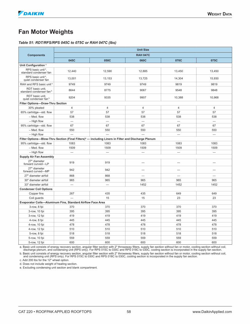
CAT 220 • ROOFPAK APPLIED ROOFTOPS 58 www.DaikinApplied.com
WeIghT daTa
Fan Motor WeightsTable 51: RDT/RFS/RPS 045C to 075C or RAH 047C (lbs)
Components
Unit Size
RAH 047C
045C 050C 060C 070C 075CUnit Configuration c
RPS basic unit a, standard condenser fan 12,440 12,590 12,885 13,450 13,450
RPS basic unit a, quiet condenser fan 13,001 13,153 13,725 14,304 15,930
RAH and RFS basic unit a 9749 9749 9749 9819 9819RDT basic unit,
standard condenser fan b 8644 8775 9067 9548 9848
RDT basic unit, quiet condenser fan b 9204 9335 9907 10,388 10,968
Filter Options—Draw-Thru Section30% pleated 4 4 4 4 4
65% cartridge—std. flow 57 57 57 57 57– Med. flow 538 538 538 538 538– High flow — — — — —
95% cartridge—std. flow 67 67 67 67 67– Med. flow 550 550 550 550 550– High flow — — — — —
Filter Options—Blow-Thru Section (Final Filters)a — including Liners in Filter and Discharge Plenum95% cartridge—std. flow 1083 1083 1083 1083 1083
– Med. flow 1509 1509 1509 1509 1509– High flow — — — — —
Supply Air Fan Assembly27" diameter
forward curved—LP 919 919 — — —
27" diameter forward curved—MP 942 942 — — —
27" diameter airfoil 868 868 — — —30" diameter airfoil 965 965 965 965 96533" diameter airfoil — — 1452 1452 1452
Condenser Coil OptionsCopper fins 267 435 435 649 649Coil guards — 15 15 23 23
Evaporator Coils—Aluminum Fins, Standard Airflow Face Area3-row, 8 fpi 370 370 370 370 370
3-row, 10 fpi 395 395 395 395 3953-row, 12 fpi 419 419 419 419 4194-row, 8 fpi 445 445 445 445 445
4-row, 10 fpi 478 478 478 478 4784-row, 12 fpi 510 510 510 510 5105-row, 8 fpi 518 518 518 518 518
5-row, 10 fpi 559 559 559 559 5595-row, 12 fpi 600 600 600 600 600
a. Basic unit consists of energy recovery section, angular filter section with 2" throwaway filters, supply fan section without fan or motor, cooling section without coil, discharge plenum, and condensing unit (RPS only). For RPS 015C to 030C and RPS 018C to 030C, cooling section is incorporated in the supply fan section.
b. Basic unit consists of energy recovery section, angular filter section with 2" throwaway filters, supply fan section without fan or motor, cooling section without coil, and condensing unit (RPS only). For RPS 015C to 030C and RPS 018C to 030C, cooling section is incorporated in the supply fan section.
c. Add 200 lbs for the 12" wheel option. d. Does not include weight of heating section. e. Excluding condensing unit section and blank compartment.
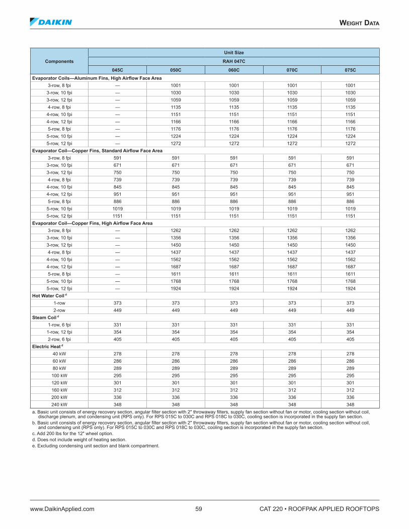
WeIghT daTa
www.DaikinApplied.com 59 CAT 220 • ROOFPAK APPLIED ROOFTOPS
Components
Unit Size
RAH 047C
045C 050C 060C 070C 075CEvaporator Coils—Aluminum Fins, High Airflow Face Area
3-row, 8 fpi — 1001 1001 1001 10013-row, 10 fpi — 1030 1030 1030 10303-row, 12 fpi — 1059 1059 1059 10594-row, 8 fpi — 1135 1135 1135 1135
4-row, 10 fpi — 1151 1151 1151 11514-row, 12 fpi — 1166 1166 1166 11665-row, 8 fpi — 1176 1176 1176 1176
5-row, 10 fpi — 1224 1224 1224 12245-row, 12 fpi — 1272 1272 1272 1272
Evaporator Coil—Copper Fins, Standard Airflow Face Area3-row, 8 fpi 591 591 591 591 591
3-row, 10 fpi 671 671 671 671 6713-row, 12 fpi 750 750 750 750 7504-row, 8 fpi 739 739 739 739 739
4-row, 10 fpi 845 845 845 845 8454-row, 12 fpi 951 951 951 951 9515-row, 8 fpi 886 886 886 886 886
5-row, 10 fpi 1019 1019 1019 1019 10195-row, 12 fpi 1151 1151 1151 1151 1151
Evaporator Coil—Copper Fins, High Airflow Face Area3-row, 8 fpi — 1262 1262 1262 1262
3-row, 10 fpi — 1356 1356 1356 13563-row, 12 fpi — 1450 1450 1450 14504-row, 8 fpi — 1437 1437 1437 1437
4-row, 10 fpi — 1562 1562 1562 15624-row, 12 fpi — 1687 1687 1687 16875-row, 8 fpi — 1611 1611 1611 1611
5-row, 10 fpi — 1768 1768 1768 17685-row, 12 fpi — 1924 1924 1924 1924
Hot Water Coil d
1-row 373 373 373 373 3732-row 449 449 449 449 449
Steam Coil d
1-row, 6 fpi 331 331 331 331 3311-row, 12 fpi 354 354 354 354 3542-row, 6 fpi 405 405 405 405 405
Electric Heat d
40 kW 278 278 278 278 27860 kW 286 286 286 286 28680 kW 289 289 289 289 289
100 kW 295 295 295 295 295120 kW 301 301 301 301 301160 kW 312 312 312 312 312200 kW 336 336 336 336 336240 kW 348 348 348 348 348
a. Basic unit consists of energy recovery section, angular filter section with 2" throwaway filters, supply fan section without fan or motor, cooling section without coil, discharge plenum, and condensing unit (RPS only). For RPS 015C to 030C and RPS 018C to 030C, cooling section is incorporated in the supply fan section.
b. Basic unit consists of energy recovery section, angular filter section with 2" throwaway filters, supply fan section without fan or motor, cooling section without coil, and condensing unit (RPS only). For RPS 015C to 030C and RPS 018C to 030C, cooling section is incorporated in the supply fan section.
c. Add 200 lbs for the 12" wheel option. d. Does not include weight of heating section. e. Excluding condensing unit section and blank compartment.
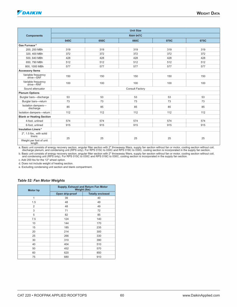
CAT 220 • ROOFPAK APPLIED ROOFTOPS 60 www.DaikinApplied.com
WeIghT daTa
Components
Unit Size
RAH 047C
045C 050C 060C 070C 075CGas Furnace d
200, 250 MBh 319 319 319 319 319320, 400 MBh 372 372 372 372 372500, 640 MBh 428 428 428 428 428650, 790 MBh 512 512 512 512 512
800, 1000 MBh 577 577 577 577 577Accessory Items
Variable frequency drive—SAF 150 150 150 150 150
Variable frequency drive—RAF 100 100 100 100 100
Sound attenuator Consult FactoryPlenum OptionsBurglar bars—discharge 53 53 53 53 53
Burglar bars—return 73 73 73 73 73Isolation dampers—
discharge 85 85 85 85 85
Isolation dampers—return 112 112 112 112 112Blank or Heating Section
4-foot, unlined 574 574 574 574 5746-foot, unlined 915 915 915 915 915
Insulation Liners e
2", 1.5 lbs., with solid liners:
25 25 25 25 25Weight per foot of unit
lengtha. Basic unit consists of energy recovery section, angular filter section with 2" throwaway filters, supply fan section without fan or motor, cooling section without coil,
discharge plenum, and condensing unit (RPS only). For RPS 015C to 030C and RPS 018C to 030C, cooling section is incorporated in the supply fan section. b. Basic unit consists of energy recovery section, angular filter section with 2" throwaway filters, supply fan section without fan or motor, cooling section without coil,
and condensing unit (RPS only). For RPS 015C to 030C and RPS 018C to 030C, cooling section is incorporated in the supply fan section. c. Add 200 lbs for the 12" wheel option. d. Does not include weight of heating section. e. Excluding condensing unit section and blank compartment.
Table 52: Fan Motor Weights
Motor hpSupply, Exhaust and Return Fan Motor
Weight (lbs)Open drip-proof Totally enclosed
1 39 401.5 48 492 48 493 71 725 82 85
7.5 124 14010 144 17015 185 23520 214 30025 266 33030 310 39040 404 51050 452 57060 620 85075 680 910
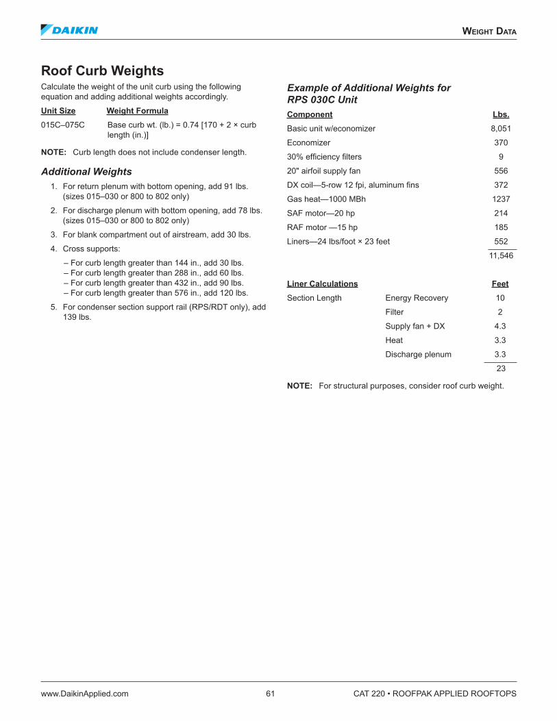
WeIghT daTa
www.DaikinApplied.com 61 CAT 220 • ROOFPAK APPLIED ROOFTOPS
Roof Curb WeightsCalculate the weight of the unit curb using the following equation and adding additional weights accordingly.
Unit Size Weight Formula 015C–075C Base curb wt. (lb.) = 0.74 [170 + 2 × curb
length (in.)]
NOTE: Curb length does not include condenser length.
Additional Weights 1. For return plenum with bottom opening, add 91 lbs.
(sizes 015–030 or 800 to 802 only)
2. For discharge plenum with bottom opening, add 78 lbs. (sizes 015–030 or 800 to 802 only)
3. For blank compartment out of airstream, add 30 lbs.
4. Cross supports:
– For curb length greater than 144 in., add 30 lbs. – For curb length greater than 288 in., add 60 lbs. – For curb length greater than 432 in., add 90 lbs. – For curb length greater than 576 in., add 120 lbs.
5. For condenser section support rail (RPS/RDT only), add 139 lbs.
Example of Additional Weights for RPS 030C Unit Component Lbs . Basic unit w/economizer 8,051
Economizer 370
30% efficiency filters 9
20" airfoil supply fan 556
DX coil—5-row 12 fpi, aluminum fins 372
Gas heat—1000 MBh 1237
SAF motor—20 hp 214
RAF motor —15 hp 185
Liners—24 lbs/foot × 23 feet 552
11,546
Liner Calculations Feet Section Length Energy Recovery 10
Filter 2
Supply fan + DX 4.3
Heat 3.3
Discharge plenum 3.3
23
NOTE: For structural purposes, consider roof curb weight.
CAT 220 • ROOFPAK APPLIED ROOFTOPS 62 www.DaikinApplied.com
engIneerIng guIde speCIfICaTIon
engIneerIng guIde speCIfICaTIon
GENERAL DESCRIPTION A. Furnish as shown on plans, Daikin RoofPak®
Singlezone Heating and Cooling Unit(s) model [RPS] [RFS] [RDT]. Unit performance and electrical characteristics shall be per the job schedule.
B. The complete unit shall be [ETL/MEA] [ETL-Canada] listed. The burner and gas train for the unit furnace shall be [UL] [IRI/FIA] [FM] approved.
C. All components included herein are designed, manufactured and independently tested, rated and certified to meet the seismic compliance standards of the International Building Code. Components designated for use in systems that are life safety, toxic, high hazard, combustible or flammable shall meet the on line, anchorage and load path requirements for life safety as defined in IBC sections 1621.1.6, 1621.3.3,1707.7.2. and IBC Commentary, Volume II, section 1621.1.6, IBC notes pertaining to the release of hazardous material. All components used as part of a system other than the above shall meet as a minimum, all load path and anchorage standards for components as outlined in IBC section 1621.3.3 & 1707.7.2. All completed component assemblies shall be clearly labeled for field inspection. Seismic Compliance Labels shall include the manufacturer’s identification, designation of certified models, definitive information describing the product’s compliance characteristics, and the Independent Certifying Agency’s name and report identification. In addition to all seismic requirements for IBC Certification listed elsewhere in the project specification, manufacturer’s submittals shall include: 1. Certificate of Compliance from the Independent
Certifying Agency clearly indicating that components supplied on this project are included in the component manufacturer’s Certificate of Compliance.
2. Clear installation instructions including all accessory components that are part of the overall component installation.
D. Each unit shall be specifically designed for outdoor rooftop application and include a weatherproof cabinet. Units shall be of a modular design with factory installed access sections available to provide maximum design flexibility. Each unit shall be [completely factory assembled and shipped in one piece] [split at the condensing section] and/ or [split (size 36-75C) between the supply fan section and the heat section]. RPS and RDT packaged units shall be shipped fully charged with Refrigerant [22] [407C]. RFR/ RCS split systems and all units split between the evaporator and the condensing section are shipped with a nitrogen holding charge only.
E. The unit shall undergo a complete factory run test prior to shipment. The factory test shall include final balancing of the supply and exhaust fan assemblies, a refrigeration circuit run test, a unit control system operations checkout, [test and adjustment of the gas furnace], a unit refrigerant leak test and a final unit inspection.
F. All units shall have decals and tags to indicate caution areas and aid unit service. Unit nameplates shall be fixed to the main control panel door. Electrical wiring diagrams shall be attached to the control panels. Installation, operating and maintenance bulletins and start-up forms shall be supplied with each unit.
G. Performance: All scheduled capacities and face areas are minimum accepted values. All scheduled amps, kW, and hp are maximum accepted values that allow scheduled capacity to be met.
H. Warranty: The manufacturer shall provide 12-month parts only warranty. [The manufacturer will provided extended 48-month, parts only, warranty on the compressor.] Defective parts will be repaired or replaced during the warranty period at no charge. The warranty period shall commence at startup or six months after shipment, whichever occurs first.
CABINET, CASING AND FRAME A. Standard double-wall construction for all side wall
access doors and floor areas shall be provided with 22 gauge solid galvanized steel inner liners to protect insulation during service and maintenance. Insulation shall be a minimum of 1" thick, 3/4-lb. density neoprene coated glass fiber. Unit cabinet shall be designed to operate at total static pressures up to 5.5 inches w.g. Insulation on ceiling and end panels shall be secured with adhesive and mechanical fasteners. [Heavy gauge solid galvanized steel liners shall be provided throughout, allowing no exposed insulation within the air stream. All cabinet insulation, except floor panels, shall be a nominal 2" thick, 1½-lb. density, R6.5, glass fiber.] [A combination of solid and perforated galvanized steel liners shall be provided throughout. Perforated liners to be used in the supply and return air plenums to provide improved sound attenuation. All cabinet insulation, except floor panels, shall be a nominal 2" thick, 1½-lb. density, R6.5, glass fiber.] All floor panels shall include [double wall construction and include a nominal 2" thick, 1½-lb. density, R6.5 glass fiber insulation.] [a minimum 1" thick, 3-lb. density, R4.2 glass fiber glass insulation.]
engIneerIng guIde speCIfICaTIon
www.DaikinApplied.com 63 CAT 220 • ROOFPAK APPLIED ROOFTOPS
B. Exterior surfaces shall be constructed of pre-painted galvanized steel for aesthetics and long term durability. Paint finish to include a base primer with a high quality, polyester resin topcoat of a neutral beige color. Finished surface to withstand a minimum 1000-hour salt spray test in accordance with ASTM B117 standard for salt spray resistance. Service doors shall be provided on both sides of each section in order to provide user access to all unit components. Service doors shall be constructed of heavy gauge galvanized steel with a gauge, galvanized steel interior liner. All service doors shall be mounted on multiple, stainless steel hinges and shall be secured by a latch system that is operated by a single, flush-mounted handle. The latch system shall feature a staggered engagement for ease of operation. Removable panels, or doors secured by multiple, mechanical fasteners are not acceptable.
C. The unit base frame shall be constructed of heavy-gauge pre-painted galvanized steel. The unit base shall overhang the roof curb for positive water runoff and shall have a formed recess that seats on the roof curb gasket to provide a positive, weather tight seal. Lifting brackets shall be provided on the unit base with lifting holes to accept cable or chain hooks.
SUPPLY AND RETURN EXHAUST FANS A. All fan assemblies shall be statically and dynamically
balanced at the factory, including a final trimbalance, prior to shipment. All fan assemblies shallemploy solid steel fan shafts. Heavy-duty pillowblock type, self-aligning, grease lubricated ballbearings shall be used. Bearings shall be sized toprovide an L-50 life at 200,000 hours. The entire fanassembly shall be isolated from the fan bulkheadand mounted on [rubber-in-shear isolators] [springisolators] [spring isolators with seismic restraints].[Fixed] [Adjustable] pitch V-belt drives with matchingbelts shall be provided. V-belt drives shall beselected at [the manufacturer’s standard servicefactor] [1.5 times fan brake horsepower].
B. Fan motors shall be heavy-duty 1800 rpm [opendrip-proof (ODP)] [totally enclosed TEFC] typewith grease lubricated ball bearings. [Motors shallbe high efficiency and meet applicable EPACTrequirements.] [Motors shall be premium efficiency.]Motors shall be mounted on an adjustable basethat provides for proper alignment and belt tensionadjustment.
C. Airfoil supply fansSupply fan shall be double width, double inlet(DWDI) airfoil centrifugal fan. All fans shall bemounted using shafts and hubs with matingkeyways. Fans shall be Class II type and fabricatedfrom heavy-gauge aluminum. Fan blades shall becontinuously welded to the back plate and end rim.
D. Forward curved supply fansSupply fan shall be double width, double inletforward curved centrifugal fan. All fans shallbe mounted using shafts and hubs with matingkeyways. The forward curved fan wheel and housingshall be fabricated form galvanized steel and shallbe [Class I] [Class II] construction to satisfy thespecified application.
E. Airfoil return/exhaust fansA single width, single inlet (SWSI) airfoil centrifugalreturn air fan shall be provided. The fan shall beClass II construction. The fan wheel shall be ClassII construction and fabricated from heavy-gaugealuminum with fan blades continuously welded to theback plate and end rim. The fan shall be mountedusing shafts and hubs with mating keyways. Exhaustfans are not acceptable.
F. [The supply air fan and return air fan sections shallbe provided with an expanded metal belt guard.]
VARIABLE AIR VOLUME CONTROL A. An electronic variable frequency drive shall be
provided for the supply [and return] air fan. [Twoindependent drives, one per fan, shall be provided.]Each drive shall be factory installed downstream ofthe filters in a manner that the drive(s) are directlycooled by the filtered, mixed air stream. Drivesshall meet UL Standard 95-5V and the variablefrequency drive manufacturer shall have specificallyapproved them for plenum duty application. Thecompleted unit assembly shall be listed by arecognized safety agency, such as ETL. Drives areto be accessible through a hinged door assemblycomplete with a single handle latch mechanism.Mounting arrangements that expose drives to hightemperature, unfiltered ambient air is not acceptable.
B. The unit manufacturer shall install all powerand control wiring. [A manual bypass contactorarrangement shall be provided. The bypassarrangement will allow fan operation at full designcfm, even if the drive has been removed for service].[Line reactors shall be factory installed for eachdrive].
C. The supply air fan drive output shall be controlledby the factory installed main unit control system anddrive status and operating speed shall be monitoredand displayed at the main unit control panel. [Thesupply and return/exhaust fan drive outputs shallbe independently controlled in order to providethe control needed to maintain building pressurecontrol. Supply and return/exhaust air fan drives thatare slaved off of a common control output are notacceptable.]
D. All drives shall be factory run tested prior to unitshipment.
CAT 220 • ROOFPAK APPLIED ROOFTOPS 64 www.DaikinApplied.com
engIneerIng guIde speCIfICaTIon
ELECTRICAL A. Unit wiring shall comply with NEC requirements
and with all applicable UL standards. All electrical components shall be UL recognized where applicable. All wiring and electrical components provided with unit shall be number and color-coded and labeled according to the electrical diagram provided for easy identification. The unit shall be provided with a factory wired weatherproof control panel. Unit shall have a [single] [dual] point power terminal block for main power connection. A terminal board shall be provided for low voltage control wiring. Branch short circuit protection, 115-volt control circuit transformer and fuse, system switches, high temperature sensor, and a 115volt receptacle with a separate electrical connection shall also be provided with unit. Each compressor and condenser fan motor shall be furnished with contactors and inherent thermal overload protection. Supply and return fan motors shall have contactors and external overload protection. Knockouts shall be provided in the bottom of the main control panels for field wiring entrance. All 115–600 voltage wire shall be protected from damage by raceways or conduit.
B. [A factory installed and wired marine service light, with switch and receptacle, shall be provided in the supply air and return/exhaust fan section. The separate, main unit service receptacle electrical circuit shall also power the light circuit.]
C. [Part winding start shall be provided for the unit compressors to reduce inrush current at start-up.]
D. [Power factor capacitors shall be factory mounted and wired to the unit compressors. Power factor capacitors shall be selected to provide correction to a minimum of 0.90.]
E. [Phase failure and under voltage protection on three-phase motors shall be provided to prevent damage from single phasing, phase reversal, and low voltage conditions.]
F. [Ground fault protection shall be provided to protect against arcing ground faults.]
G. Further options 1. Factory-mounted smoke detectors shall be
factory installed in the [supply air opening] [supply and return air openings]. Smoke detectors to be ionization type, which responds to invisible products of combustion without requiring the sensing of heat, flame or visible smoke. Upon sensing smoke, the unit shall provide a control output for use by building management system.
2. Unit to have factory-mounted UV lights located on the leaving air side of the cooling coil. Unit to have view port to allow for visual indication of operation through UV resistant glass. Unit to have door interlocks on each door accessing UV light. Interlock to kill power to UV light when door is opened.
Lamp and fixture to consist of a housing, power source, lamp sockets, and lamp. All components are to be constructed to withstand typical HVAC environments and are UL/C-UL listed. Housings are to be constructed of type 304 stainless steel and are to be equipped with both male and female power plugs with one type at each end to facilitate simple fixture-to-fixture plug-in for AC power. Power source shall be an electric, rapid-type with overload protections and is to be designed to maximize radiance and reliability at UL/C-UL listed temperatures of 55°F–135°F. Power source will include RF and EMI suppression. Sockets shall be medium bi-pin, single click safety, twist lock type and are to constructed of a UVC-resistant poly carbonate. Lamp shall be a high output, hot cathode, T8 diameter, medium bi-pin that produces UVGI of 254 nm. Each tube produces the specified output at 500 fpm and air temperatures of 55°F–135°F.
3. A [single] [dual] non-fused disconnect switch[es] shall be provided for disconnecting electrical power at the unit. [The second switch will service the condensing section.] Disconnect switches shall be mounted internally to the control panel and operated by an externally-mounted handle. Externally-mounted handle is designed to prohibit opening of the control panel door without the use of a service tool.
HEATING AND COOLING SECTIONS Cooling
A. [The cooling coil section shall be installed in a blow-through configuration, downstream of the supply air fan. A factory-tested diffuser shall be used in order to provide air distribution across the cooling coil. A blow-through coil is specified to minimize the impact of fan motor heat.] [The cooling coil section shall be installed in a draw through configuration, upstream of the supply air fan.] The coil section shall be complete with factory piped cooling coil and sloped drain pan. Hinged access doors on both sides of the section shall provide convenient access to the cooling coil and drain pan for inspection and cleaning. Submittals must demonstrate that scheduled unit leaving air temperature (LAT) is met, that fan and motor heat temperature rise (TR) have been considered, and scheduled entering air temperature (EAT) equals mixed air temperature (MAT). Draw-through cooling—Scheduled EAT equals cooling coil EAT and scheduled unit LAT equals cooling coil LAT plus TR. Blow-through cooling—Cooling coil EAT equals scheduled EAT plus TR and scheduled unit LAT equals cooling coil LAT.
engIneerIng guIde speCIfICaTIon
www.DaikinApplied.com 65 CAT 220 • ROOFPAK APPLIED ROOFTOPS
Direct expansion (DX) cooling coils shall be fabricated of seamless 1/2" diameter high efficiency copper tubing that is mechanically expanded into high efficiency [aluminum] [copper] plate fins. Coils shall be a multi-row, staggered tube design with a minimum of [3] [4] [5] rows and a maximum of [8] [10] [12] fins per inch. All units shall have two independent refrigerant circuits and shall use an interlaced coil circuiting that keeps the full coil face active at all load conditions. All coils shall be factory leak tested with high pressure air under water.
B. A [painted galvanized steel,] [stainless steel,] positively sloped drain pan shall be provided with the cooling coil. The drain pan shall extend beyond the leaving side of the coil and underneath the cooling coil connections. The drain pan shall have a minimum slope of 1/8" per foot to provide positive draining. The drain pan shall be connected to a threaded drain connection extending through the unit base. Units with stacked cooling coils shall be provided with a secondary drain pan piped to the primary drain pan.
Hot Water Heating Option C. A [1] [2] row hot water heating coil shall be factory
installed in the unit heat section. Coils shall be fabricated of seamless 5/8" diameter copper tubing that is mechanically expanded into high efficiency HI-F rippled and corrugated aluminum plate fins. All coil vents and drains shall be factory installed. The hot water heat section shall be installed downstream of the supply air fan. A factory-tested diffuser shall be used in order to provide air distribution across the coil. Hinged access doors shall provide convenient access to the coil and valve for inspection and cleaning. [A factory installed three-way modulating control valve and spring return valve actuator shall provide control of the hot water coil. The valve actuator shall be controlled by the factory installed main unit control system] [[Ethylene glycol] [propylene glycol] shall be added to the hot water circuit to protect against coil freeze-up.] [A factory installed, non-averaging type freezestat shall be factory installed to provide some protection against coil freeze-up.] Coils shall be factory leak tested with high pressure air under water.
Steam Heating Option D. A [1 row, 6 fin per inch] [1 row, 12 fin per inch] [2
row, 6 fin per inch] fin per inch team heating coil shall be factory installed in the unit heat section. Coils shall be fabricated of seamless 5/8” diameter copper tubing that is mechanically expanded into high efficiency HI-F rippled and corrugated aluminum plate fins. Steam coils shall be of the jet distributing type. The steam heat section shall be installed downstream (RFS/RPS) of the supply air fan. A factory-tested diffuser shall be used in order to provide air distribution across the coil. Hinged access doors shall provide convenient access to the coil and valve for inspection and cleaning. [A factory installed two-way modulating control valve and spring return valve actuator shall provide control of the steam coil. The valve actuator shall be controlled by the factory installed main unit control system] [A factory installed, non-averaging type freezestat shall be factory installed to provide some protection against coil freeze-up.] Coils shall be factory leak tested with high pressure air under water.
Gas Heating Option E. A natural gas fired furnace shall be installed in
the unit heat section. The heat exchanger shall include a type 321 stainless steel cylindrical primary combustion chamber, a type 321 stainless steel header, type 321 stainless steel] secondary tubes and type 321stainless steel turbulators. Carbon and aluminized steel heat exchanger surfaces are not acceptable. The heat exchanger shall have a condensate drain. Clean out of the primary heat exchanger and secondary tubes shall be accomplished without removing casing panels or passing soot through the supply air passages. The furnace section shall be positioned downstream of the supply air fan. [The furnace will be supplied with a modulating forced draft burner. The burner shall be controlled for low fire start. The burner shall be capable of continuous modulation between 33% and100% of rated capacity and shall operate efficiently at all firing rates.] [The furnace shall be supplied with a Daikin SuperMod™ forced draft burner capable of continuous modulation between 5% and 100% of rated capacity, without steps. The burner shall operate efficiently at all firing rates. The burner shall have proven open damper low-high-low pre-purge cycle, and proven low fire start. The combustion air control damper shall be in the closed position during the off cycle to reduce losses.]
CAT 220 • ROOFPAK APPLIED ROOFTOPS 66 www.DaikinApplied.com
engIneerIng guIde speCIfICaTIon
The burner shall be specifically designed to burn natural gas and shall include a microprocessor based flame safeguard control, combustion air proving switch, prepurge timer and spark ignition. The gas train shall include redundant gas valves, [maximum 0.5psi pressure regulator] [2–3psi high pressure regulator] [5–10psi high pressure regulator], shutoff cock, pilot gas valve, pilot pressure regulator, and pilot cock. The burner shall be rated for operation and full modulation capability at inlet gas pressures down to [7.0. W.C. (models 200–650)] [8.0 in. W.C. (models 790, 800] [9.0 in. W.C. (model 100)]. The gas burner shall be controlled by the factory installed main unit control system. The burner shall be fired, tested and adjusted at the factory. Final adjustments shall be made in the field at initial startup by a qualified service technician to verify that installation and operation of the burner is according to specifications.
Electric Heating Option F. Staged electric heating coils shall be factory
installed in the unit heat section. Heating coils shall be constructed of a low watt density, high nickel-chromium alloy resistance wire, mechanically stacked and heli-arc welded to corrosion resistant terminals. A corrosion resistant heavy gauge rack shall support the elements. Safety controls shall include automatic reset high limit control for each heater element with manual reset backup line break protection in each heater element branch circuit (Note: Manual reset not provided when ETL-Canada label is provided). Heating element branch circuits shall be individually fused to maximum of 48 Amps per NEC requirements. The electric heat section shall be positioned downstream of the supply air fan. The electric heat elements shall be controlled by the factory installed main unit control system.
FILTERS Draw-through Filters
A. Unit shall be provided with a draw-through filter section. The filter section shall be supplied complete with the filter rack as an integral part of the unit. The draw-through filter section shall be provided with [panel] [cartridge] filters.
B. 2" thick AmericanAirFilter 30% efficient pleated panel filters shall be provided. Filters shall be frame mounted and shall slide into galvanized steel racks contained within the unit. Filters shall be installed in an angular arrangement to maximize filter area and minimize filter face velocity. Filters shall be accessible from both sides of the filter section.
C. [12" deep [60-65%] [90-95%] efficient, UL Std. 900, Class 1, AmericanAirFilter cartridge filters shall be provided. 2" panel, 30% efficient pre-filters shall be included. Cartridge filters shall consist of filter media permanently attached to a metal frame and shall slide into a gasketed, extruded aluminum rack contained within the unit. The filter rack shall have secondary gasketed, hinged end panels to insure proper sealing. Filters shall be accessible from both sides of the filter section.]
D. [[30% efficient pleated] [60-65% efficient cartridge] [90– 95% efficient cartridge] filters shall be provided with INTERSEPT® antimicrobial treatment.]
Final Filters Option E. Final Filters—Unit shall be provided with a final filter
section downstream of the supply fan. Unit to have 40" of unit length between the fan discharge and the final filters to allow for proper air distribution. The final filter section shall be supplied complete with the filter rack as an integral part of the unit. The final filter section shall be provided with cartridge filters.
F. [12" deep [60-65%] [90-95%] efficient, UL Std. 900, Class 1, AmericanAirFilter cartridge filters shall be provided. 2" panel, 30% efficient pre-filters shall be included. Cartridge filters shall consist of filter media permanently attached to a metal frame and shall slide into a gasketed, extruded aluminum rack contained within the unit. The filter rack shall have secondary gasketed, hinged end panels to insure proper sealing. Filters shall be accessible from both sides of the filter section.]
G. [Filters shall be provided with INTERSEPT® antimicrobial treatment.]
OUTDOOR / RETURN AIR SECTION Return Air Plenum
A. Daikin UltraSeal™ low leak dampers shall be provided. Damper blades shall be fully gasketed and side sealed and arranged horizontally in the hood. Damper leakage shall be less than 0.2% at 1.5 inches static pressure differential. Leakage rate to be tested in accordance with AMCA Standard 500. Damper blades shall be operated from multiple sets of linkages mounted on the leaving face of the dampers. [Control of the dampers shall be from a factory installed, two-position actuator.]
engIneerIng guIde speCIfICaTIon
www.DaikinApplied.com 67 CAT 220 • ROOFPAK APPLIED ROOFTOPS
B. Unit shall be provided with [a modulating outdoor air economizer section with] an ARI Certified energy recovery wheel. [The economizer section shall include outdoor, return and return exhaust air control and bypass dampers and damper actuators shall be included that automatically bypass outdoor air around the wheel during economizer operation.] Outdoor air shall enter at the back of the section through a factory installed hood capable of handling 100% outdoor air. The outdoor air hood shall be factory installed and constructed from galvanized steel finished with the same prepainted finish as the main unit. The hood shall include a bird screen to prevent infiltration of foreign materials and a rain lip to drain water away from the entering air stream. Return air shall enter through the bottom of the unit. The entire section shall be double wall construction.
C. The enthalpy wheel shall be constructed of corrugated synthetic fibrous media, with a desiccant intimately bound and uniformly and permanently dispersed throughout the matrix structure of the media. Rotors with desiccants coated, bonded, or synthesized onto the media are not acceptable due to delamination or erosion of the desiccant material. Media shall be synthetic to provide corrosion resistance and resistance against attack from laboratory chemicals present in pharmaceutical, hospital, etc. environments as well as attack from external outdoor air conditions. Coated aluminum is not acceptable. Face flatness of the wheel shall be maximized (+/- 0.032 in) in order to minimize wear on inner seal surfaces and to minimize cross leakage. Rotor shall be constructed of alternating layers of flat and corrugated media. Wheel layers should be uniform in construction forming uniform aperture sizes for airflow. Wheel construction shall be fluted or formed honeycomb geometry so as to eliminate internal wheel bypass. Wheel layers that can be separated or spread apart by airflow are unacceptable due to the possibility of channeling, internal bypass or leakage, and performance degradation. The media shall be in accordance with NFPA or UL guidelines. The desiccant material shall be a molecular sieve, and specifically a 4A or smaller molecular sieve to minimize cross contamination. The wheel frames shall consist of evenly spaced steel spokes, galvanized steel outer band and rigid center hub. The wheel construction should allow for post fabrication wheel alignment. The wheel seals shall be brush seals, neoprene bulb seals or equivalent. Seals should be easily adjustable. Cassettes shall be fabricated of heavy duty reinforced galvanized steel. Cassettes shall have a built in adjustable purge section minimizing cross contamination of supply air. Bearings shall be inboard, zero maintenance, permanently sealed roller bearings, or alternatively, external flanged bearings. Drive systems shall consist of fractional horsepower A.C. drive motors with multilink drive belts.
The wheel capacity, air pressure drop, and efficiency shall be tested in accordance with NFPA or UL guidelines and shall be UL recognized or equivalent. The wheel capacity, air pressure drop and effectiveness shall be ARI certified by ARI and its testing agencies. Alternative independent performance testing must be pre-approved to be accepted. [Wheel shall be provided with variable speed control for frost protection].
D. The wheel recovers energy from the factory-supplied return/exhaust section and includes an SWSI airfoil fan and motor in accordance with construction already specified. Gravity relief dampers and fold out exhaust hood shall be provided. All necessary exhaust fan motor starters, branch short circuit protection, and wiring and controls shall be provided. Two inch, 30% pleated filters shall be provided in both air inlets to protect the wheel from dust and dirt in both the outdoor and return/exhaust air paths. Dampers to be Daikin UltraSeal low leak type, and shall be provided on outdoor or return dampers. Damper blades shall be fully gasketed and side sealed and arranged horizontally in the hood. Damper leakage shall be less than 0.2% at 1.5 inches static pressure differential. Leakage rate to be tested in accordance with AMCA Standard 500. Damper blades shall be operated from multiple sets of linkages mounted on the leaving face of the dampers.
ACCESS SECTION OPTION A. Unit shall be provided with factory installed access
sections located [upstream] [downstream] [upstream and downstream] of the supply air fan, as shown on the unit drawing. Access sections shall have hinged access doors on both sides of the section and shall have the same construction features as the rest of the unit.
Blank Compartment B. An insulated, blank compartment shall be provided.
The section shall be located after the discharge plenum and will be out of the air stream. The section shall be complete with insulation, double wall construction [and a service light].
CAT 220 • ROOFPAK APPLIED ROOFTOPS 68 www.DaikinApplied.com
engIneerIng guIde speCIfICaTIon
SOUND ATTENUATOR OPTION A. A section shall be provided by the air handling
unit manufacturer as an integral part of the unit to attenuate fan noise at the source. Variable range of splitter thickness and air passages provided to optimize acoustic performance and energy conservation. The attenuators shall have perforated double-wall construction and be located downstream of the supply fan. Hinged access doors shall be provided on both sides of the section and shall have the same construction as the rest of the unit. [Sound attenuator shall have Tedlar coating for moisture protection]. Combustion rating for the silencer acoustic fill shall not be greater than the following UL fire hazard classification: Flame Spread . . . . . . . . . . . . . . . 15Fuel Contributed . . . . . . . . . . . . . . 0Smoke Developed . . . . . . . . . . . . . 0
Tested in accordance with UL Test Procedure 723. B. The attenuator rating shall be determined using the
duct-toreverberant room test method which provides for airflow in both directions through the attenuator in accordance with latest version of ASTM specification E-477. Insertion Loss Ratings (ILR) shall be:
Octave Band at Center Frequency (Hz)63 125 250 500 1000 2000 4000 8000
ILR (no Tedlar) 7 9 22 28 29 29 18 12ILR (Tedlar coating) 6 10 20 16 14 18 13 12
C. Manufacturer shall provide certified test data on dynamic insertion loss, self-generated sound power levels, and aerodynamic performance for reverse and forward flow test conditions to the design professional in writing as least 10 days prior to the bid.
DISCHARGE AND RETURN PLENUM ACCESSORIES
A. A supply air discharge plenum shall be provided. [The plenum section shall be lined with a perforated acoustic liner to enhance sound attenuation.] The plenum section shall have a [bottom] [side] [front (RFR only)] discharge opening.
B. A combination burglar bar/safety grate shall be provided in the [bottom return air opening] [bottom supply air opening] [bottom return and supply air openings]. Burglar bar/safety grate shall be made of 3/4" diameter ground and polished steel shaft welded to a galvanized steel frame.
C. Isolation dampers shall be provided in the [bottom return air opening] [bottom supply air opening] [bottom return and supply air openings]. [A two-position actuator shall be provided to close the dampers when the fans are not running.]
CONDENSING UNIT SECTION A. The condensing section shall be open on the sides
and bottom to provide access and to allow airflow through the coils. Condenser coils shall be multi-row and fabricated from 3/8" high efficiency rifled copper tubing mechanically bonded to high efficiency aluminum fins. Each condenser coil shall be factory leak tested with high-pressure air under water. [Condenser coil guards shall provide protection from incidental contact to coil fins. Coil guards to be constructed of cross wire welded steel with PVC coating.]
B. Condenser fans shall be direct drive, propeller type designed for low tip speed and vertical air discharge. [Condenser fan rpm shall be 1140 rpm maximum.] [Condenser fans shall have airfoil blades, discharge shrouds for quiet operation, and shall run at 850 maximum rpm.] Fan blades shall be constructed of steel and riveted to a steel center hub. Condenser fan motors shall be heavy-duty, inherently protected, three-phase, non-reversing type with permanently lubricated ball bearing and integral rain shield.
C. Each circuit shall have fan cycling of at least one condenser fan to maintain positive head pressure. An ambient thermostat shall prevent the refrigeration system from operating below 45ºF. [SpeedTrol™ condenser fan speed control shall be added to the last fan off on each refrigeration circuit to provide cooling operation to ambient temperatures down to 0°F. Fan speed control shall be field adjustable (size 36-75C only).]
D. Each unit shall have multiple, heavy-duty Copeland scroll compressors. Each compressor shall be complete with gauge ports, crankcase heater, sight-glass, anti-slug protection, motor overload protection and a time delay to prevent short cycling and simultaneous starting of compressors following a power failure. Compressors shall be isolated with resilient rubber isolators to decrease noise transmission.
E. Each unit shall have two independent refrigeration circuits. Each circuit shall be complete with a liquid line solenoid valve, low pressure control, filter-drier, liquid moisture indicator/sight-glass, thermal expansion valve, liquid line shutoff valve with charging port, discharge line shutoff valve, a manual reset high pressure safety switch, high pressure relief device and pump down switch. The thermal expansion valve shall be capable of modulation from 100% to 25% of its rated capacity. Sight-glasses shall be accessible for viewing without disrupting unit operation. Each refrigerant circuit shall include a subcooling circuit to provide 15 degrees of liquid subcooling. Each circuit shall be dehydrated and factory charged with Refrigerant [22] [407C] and oil.
engIneerIng guIde speCIfICaTIon
www.DaikinApplied.com 69 CAT 220 • ROOFPAK APPLIED ROOFTOPS
F. Refrigeration capacity control shall be accomplished by staging of the unit’s multiple compressors. To maintain desired temperature control, the unit shall have a minimum of [three] [four] [six] steps of capacity control.
G. All compressor capacity control staging shall be controlled by the factory installed main unit control system.
H. All compressor capacity control staging shall be controlled by the factory installed main unit control system.
Hot Gas Bypass I. Hot gas bypass control shall be factory installed
on one [both] refrigerant circuits. Hot gas bypass control shall include a modulating hot gas bypass control valve, solenoid valve, all associated piping and be automatically operated by the units microprocessor control.
ROOF CURB A. A prefabricated 12-gauge galvanized steel, mounting
curb, designed and manufactured by the unit manufacturer, shall be provided for field assembly on the roof decking prior to unit shipment. The roof curb shall be a full perimeter type with complete perimeter support of the air handling section and rail support of the condensing section. Supply and return opening duct frames shall be provided as part of the curb structure allowing duct connections to be made directly to the curb prior to unit arrival. The curb shall be a minimum of 16" high and include a nominal 2" × 4" wood nailing strip. Gasket shall be provided for field mounting between the unit base and roof curb.
CONTROLS A. Each unit shall be equipped with a complete
MicroTech® II microprocessor based control system. The unit control system shall include all required temperature and pressure sensors, input/output boards, main microprocessor and operator interface. The unit control system shall perform all unit control functions including scheduling,], unit diagnostics and safeties. Control sequences shall include [constant air volume, zone temperature control (CAV-ZTC)] [constant air volume, discharge temperature control (CAV-DTC)] [variable air volume, cooling only discharge temperature control (VAV-DTC)] [variable air volume, cooling/modulating heating discharge temperature control (VAV-DTC)] [duct static pressure control], [supply/ return air fan tracking control] and [building static pressure control. All boards shall be individually replaceable for ease of service. All microprocessors, boards, and sensors shall be factory mounted, wired and tested.
B. The microprocessor shall be a stand-alone DDC controller not dependent on communications with any on-site or remote PC or master control panel. The microprocessor shall maintain existing set points and operate stand alone if the unit loses either direct connect or network communications. The microprocessor memory shall be protected from voltage fluctuations as well as any extended power failures. All factory and user set schedules and control points shall be maintained in nonvolatile memory. No settings shall be lost, even during extended power shutdowns.
C. The main microprocessor shall support an RS-232 direct connection to a product service tool or a modem. A [BACnet ethernet] [BACnet MSTP] [LonTalk] communications port shall be provided for direct communication into the BAS network.
D. All digital inputs and outputs shall be protected against damage from transients or wrong voltages. Each digital input and digital output shall be equipped with an LED for ease of service. All field wiring shall be terminated at a separate, clearly marked terminal strip.
E. The microprocessor memory shall be protected from all voltage fluctuations as well as any extended power failures. The microprocessor shall support an RS-232 direct connect from an IBM PC or 100% true compatible using MicroTech software. The microprocessor shall maintain existing set points and operate stand alone if the rooftop loses either direct connect or network communications.
F. The microprocessor shall have a built-in time schedule. The schedule shall be programmable from the unit keypad interface. The schedule shall be maintained in nonvolatile memory to insure that it is not lost during a power failure. There shall be one start/stop per day and a separate holiday schedule. The controller shall accept up to sixteen holidays each with up to a 5-day duration. Each unit shall also have the ability to accept a time schedule via BAS network communications. G If the unit is to be programmed with a night setback or setup function, an optional space sensor shall be provided. Space sensors shall be available to support field selectable features. Sensor options shall include: 1. Zone sensor with tenant override switch. 2. #1 above plus a heating and cooling set point
adjustment. (CAV-ZTC only) H. The keypad/display character format shall be 20
characters × 4 lines. The character font shall be a 5 × 8 dot matrix. The display shall be a supertwist liquid crystal display (LCD) with black characters on yellow background providing high visibility. The display form shall be in plain English coded formats. Lookup tables are not acceptable.
CAT 220 • ROOFPAK APPLIED ROOFTOPS 70 www.DaikinApplied.com
engIneerIng guIde speCIfICaTIon
I. The keypad shall be equipped with 8 individual touch-sensitive membrane key switches. All control settings shall be password protected from changes by unauthorized personnel.
J. [Both a unit-mounted and remote-mounted UI shall be provided. A unit-mounted switch brings either the unit-mounted or remote-mounted UI into control. The control contractor is responsible for wiring between the unit and the remote UI. The maximum wiring distance to the remote UI is 1200 feet. Optical isolation shall protect the main unit controller from remote UI wiring problems. The remote UI shall be provided with the same keypad/display and have identical functionality to the unit-mounted UI.]
K. The display shall provide the following information as required by selected unit options: 1. Supply, outdoor and space air temperature 2. Supply, return, outdoor, and space air
temperature 3. Duct and building static pressure; the control
contractor is responsible for providing and installing sensing tubes
4. Supply fan and return fan status and airflow verification
5. Supply and return VFD speed 6. Outside air damper position and economizer
mode 7. Cooling and heating changeover status 8. Occupied, unoccupied, and dirty filter status 9. Date and time schedules
10. Up to four current alarms and eight previous alarms with time and date
L. The keypad shall provide the following set points as a minimum as required by selected unit options: 1. Supply, outdoor and space air temperature 2. Six control modes including off manual, auto,
heat/cool, cool only, heat only, and fan only 3. Four occupancy modes including auto, occupied,
unoccupied and bypass (tenant override with adjustable duration)
4. Control changeover based on return air temperature, outdoor air temperature, or space temperature
5. Primary cooling and heating set point temperature based on supply or space temperature
6. Night setback and setup space temperature 7. Cooling and heating control differential (or dead
band) 8. Cooling and heating supply temperature reset
options based on one of the following: Return air temperature, outdoor air temperature, space temperature, airflow, or external (1-5 VDC) signal
9. Reset schedule temperature 10. High supply, low supply, and high return air
temperature alarm limits 11. Ambient compressor and heat lockout
temperatures 12. Auto or manual lead lag method on compressors 13. Compressor interstage timers duration 14. Duct and building static pressure 15. Return fan tracking (VaneTrol) settings that
include minimum/maximum VFD speed with and without remote exhaust operation
16. Minimum outdoor airflow reset based on external reset (1-5 VFD) percent of cfm capacity, and fixed outdoor damper position
17. Minimum outdoor airflow reset based on DesignFlow direct OA volume measurement, percent of cfm capacity, and fixed outdoor damper position
18. Economizer changeover based on enthalpy, dry bulb or network signal
19. Current time and date 20. Occupied/unoccupied time schedules with
allowances for holiday/event dates and duration 21. Three types of service modes including timers
normal (all time delays), timers fast (all time delays 20 seconds), and normal
M. Open Communications Protocol-The unit control system shall have the ability to communicate to an independent Building Management System (BMS) through a direct [BACnet ethernet] [BACnet MSTP] [LonTalk] communication connection. The independent BMS system shall have access to [quantity from specification] “read only’ variables and [quantity from specification] “read and write” variables. Communications shall not require field mounting of any additional sensors or devices at the unit. [The communications protocol shall be LONMARK 3.3 certified under the [Discharge Air] [Space Comfort] functional profiles.] The BMS system shall be capable of interacting with the individual rooftop controllers in the following ways: 1. Monitor controller inputs, outputs, set points,
parameters and alarms 2. Set controller set points and parameters 3. Clear alarms 4. Reset the cooling and heating discharge air
temperature set point (VAV and CAV-DTC units) 5. Reset the duct static pressure set point (VAV
units) 6. Set the heat/cool changeover temperature (VAV
and CAV-DTC units) 7. Set the representative zone temperature (CAV-
ZTC units)
engIneerIng guIde speCIfICaTIon
www.DaikinApplied.com 71 CAT 220 • ROOFPAK APPLIED ROOFTOPS
N. It will be the responsibility of the Systems Integrating Contractor to integrate the rooftop data into the BMS control logic and interface stations. 1. Minimum outdoor airflow reset based on
DesignFlow direct OA volume measurement, percent of cfm capacity, and fixed outdoor damper position
2. Economizer changeover based on enthalpy, dry bulb or network signal
3. Current time and date 4. Occupied/unoccupied time schedules with
allowances for holiday/event dates and duration 5. Three types of service modes including timers
normal (all time delays), timers fast (all time delays 20 seconds), and normal
O. Open Communications Protocol—The unit control system shall have the ability to communicate to an independent Building Management System (BMS) through a direct [BACnet ethernet] [BACnet MSTP] [LonTalk] communication connection. The independent BMS system shall have access to [quantity from specification] “read only’ variables and [quantity from specification] “read & and write” variables. Communications shall not require field mounting of any additional sensors or devices at the unit. [The communications protocol shall be LONMARK 3.3 certified under the [Discharge Air] [Space Comfort] functional profiles.] The BMS system shall be capable of interacting with the individual rooftop controllers in the following ways: 1. Monitor controller inputs, outputs, set points,
parameters and alarms 2. Set controller set points and parameters 3. Clear alarms 4. Reset the cooling and heating discharge air
temperature set point (VAV and CAV-DTC units) 5. Reset the duct static pressure set point (VAV
units) 6. Set the heat/cool changeover temperature (VAV
and CAV-DTC units) 7. Set the representative zone temperature (CAV-
ZTC units) P. It will be the responsibility of the Systems Integrating
Contractor to integrate the rooftop data into the BMS control logic and interface stations.
EXECUTION Installation Install in accordance with manufacturer’s instructions.
Daikin Applied Training and DevelopmentNow that you have made an investment in modern, efficient Daikin equipment, its care should be a high priority. For training information on all Daikin HVAC products, please visit us at www.DaikinApplied.com and click on Training, or call 540-248-9646 and ask for the Training Department.
Warranty
All Daikin equipment is sold pursuant to its standard terms and conditions of sale, including Limited Product Warranty. Consult your local Daikin Applied representative for warranty details. To find your local Daikin Applied representative, go to www.DaikinApplied.com.
Aftermarket Services
To find your local parts office, visit www.DaikinApplied.com or call 800-37PARTS (800-377-2787). To find your local service office, visit www.DaikinApplied.com or call 800-432-1342.
This document contains the most current product information as of this printing. For the most up-to-date product information, please go to www.DaikinApplied.com.
Products manufactured in an ISO Certified Facility.
CAT 220 (10/16) ©2016 Daikin Applied | (800) 432–1342 | www.DaikinApplied.com