Embed Size (px)
Citation preview
OM
111
1-2
Mic
roTe
ch C
ontro
ller
Operation and Maintenance Manual OM 1111-2Group: Applied Air SystemsPart Number: OM 1111Date: October 2015
MicroTech® Unit Controller with I/O Expansion Module for Fan CoilsModels FCHH / FCHC / FCHR and Cabinet Unit Heaters, Models FHHH / FHHC / FHHR
Introduction . . . . . . . . . . . . . . . . . . . . . . . . . . . . . . . . . . 3General Use and Information . . . . . . . . . . . . . . . . . . . 3
MicroTech Baseboard . . . . . . . . . . . . . . . . . . . . . . . . . 4Control Inputs . . . . . . . . . . . . . . . . . . . . . . . . . . . . . . . 4Control Outputs . . . . . . . . . . . . . . . . . . . . . . . . . . . . . . 5
I/O Expansion Module . . . . . . . . . . . . . . . . . . . . . . . . . 6Control Boards Terminals and Connectors Descriptions . . . . . . . . . . . . . . . . . . . . . . . . . . . . . . . . . 8Fan Coil/Cabinet Unit Heater Unit Control . . . . . . . . 13
Fan Coil/Cabinet Unit Heater Control Output Tables . . . . . . . . . . . . . . . . . . . . . . . . . . . . . . 13Operating Modes . . . . . . . . . . . . . . . . . . . . . . . . . . . . 15
Alarms . . . . . . . . . . . . . . . . . . . . . . . . . . . . . . . . . . . . 20
Miscellaneous Control Definitions . . . . . . . . . . . . . . 21Appendix A . . . . . . . . . . . . . . . . . . . . . . . . . . . . . . . . . 23
Replacing a MicroTech Circuit Board . . . . . . . . . . . 23Appendix B . . . . . . . . . . . . . . . . . . . . . . . . . . . . . . . . . 24
MicroTech Unit Controller with an optional LonWorks® Communication Module . . . . . . . . . . . . . 24
Appendix C . . . . . . . . . . . . . . . . . . . . . . . . . . . . . . . . . 25MicroTech Unit Controller with an optional BACnet Communication Module . . . . . . . . . . . . . . . 25
Appendix D . . . . . . . . . . . . . . . . . . . . . . . . . . . . . . . . . 26Typical Wiring Diagrams . . . . . . . . . . . . . . . . . . . . . . 26
OM 1111-2 • MICROTECH UNIT CONTROLLER 2 www .DaikinApplied .com
IntroductIon
This Operation Manual covers the MicroTech® Unit Controller for the Daikin ThinLine Fan Coils . For information on LonWorks® or BACnet® communication modules and other ancillary components, see:
• IM 1012 — MicroTech III Fan Coil LonWorks Communication Module .
• IM 1013 — MicroTech III Fan Coil Unit Controller BACnet MS/TP Communication Module .
• IM 933 — LonWorks Plug-In Software for use with MicroTech III Unit Controller - LonWorks Communication Module .
• IM 1171 — Digitally Adjustable Display Sensor Installation and Maintenance Manual
• OM 1095 — MicroTech III The Downloading And Configuration Procedure
• ED 15135 — MicroTech III Fan Coil Unit Controller Protocol Information
For information on ThinLine Fan Coils and Cabinet Unit Heaters see
• Catalog 724 — ThinLine Horizontal Fan Coils (Type FCHC, FCHH, and FCHR)
• Catalog 725 — ThinLine Horizontal Cabinet Unit Heaters (Type FHHC, FHHH, and FHHR)
• IM 1152 — Installation Manual Daikin ThinLine Horizontal Fan Coils and Cabinet Unit Heaters (Type FC and FH Horizontal Design) .
General Use and InformationThe MicroTech unit controller is a fan coil/cabinet unit heater control platform used to control the fan coil/unit heater in all modes of operation, including economizers, control valves, and all components used to control conditioned space temperature . By adding a communication module, (LonWorks or BACnet) network integration is possible . The controller can be used with wall sensor control only .
No outside power sources may be used to operate MicroTech controller . All units must be properly grounded per local code requirements . See the Installation Manual IM 1152 for specific power requirements .
IntroductIon
www .DaikinApplied .com 3 OM 1111-2 • MICROTECH UNIT CONTROLLER
Control Inputs The baseboard accepts the following analog and binary control inputs:
1 . Room Temp and Tenant Override . . . . . . . . . . . . . Analog
2 . Local Setpoint Adjust . . . . . . . . . . . . . . . . . . . . . . . Analog
3 . Fan Mode/Speed Switch . . . . . . . . . . . . . . . . . . . . Analog
4 . Entering Water Temperature (EWT) . . . . . . . . . . . Analog
5 . Discharge Air Temperature (DAT) . . . . . . . . . . . . . Analog
6 . Heat/Cool/Auto Mode Switch . . . . . . . . . . . . . . . . Analog
7 . Freeze Fault Detection . . . . . . . . . . . . . . . . . . . . . . Binary
8 . Occupancy Sensor . . . . . . . . . . . . . . . . . . . . . . . . Binary
9 . Condensate Overflow . . . . . . . . . . . . . . . . . . . . . . Binary
Input Description
Room or Return Air Temp & Tenant OverrideAnalog input may be used to measure Room or Return Air temperature using a 10k NTC thermistor . The same analog input is used to sense the position of the timed override switch when a room sensor is applied . This sensor is mandatory in the Fan Coil/Cabinet Unit Heater units unless the input value is provided through network communications .
Condensate OverflowAnalog input may be used to detect the presence of water in condensate pan . While the input is analog (microOhms), the result of the algorithm is binary (dry or wet) . If the value is below 2 .5 microOhms, the pan is dry . If the value is above 2 .5 microOhms, the pan is wet . Ultimately the pan is considered dry for analog inputs above 1 .8 VDC .
Local Setpoint AdjustAnalog input may be used to determine hardwired setpoint position based on a 1.5K Ω potentiometer that is mounted on the room temperature sensor . Setpoint is at its minimum value at 0 Ohms (0 .0 VDC), maximum value at 1 .5K Ohms (3 .0 VDC) . Range of input is determined by the setting of an equipment configuration bit. Long range input is limited by Max and Min clamp settings . Either “Short” or “Long” range is selected during the unit order and preset at the Daikin factory . See “nciSoftJumpers” in Table 18 for specification details.
• If “Short Range” is selected, the nvoSetptShift variables are used .
• If “Long Range” is selected, the nvoSetpoint variable is used .
Fan Mode/Speed SwitchAnalog input may be used to determine the position of the fan mode and speed switch. Input DC voltages are defined as follows: 0 .0v = Auto, 1 .0v = High, 2 .0v = Medium, 3 .0v = Low, 4 .0v = Off, 5 .0v = Switch is not present .
Entering Water Temperature (EWT)Analog input may be used to measure temperature of water entering the hydronic coil using a 10k NTC thermistor . The sensor is only required in 2-Pipe Cooling/Heating systems or Heating-only with Supplemental Electric Heat, and is optional elsewhere .
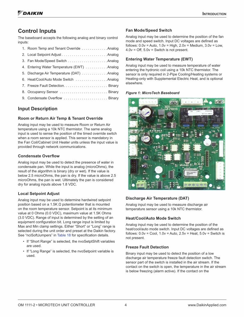
Figure 1: MicroTech Baseboard
Discharge Air Temperature (DAT)Analog input may be used to measure discharge air temperature sensor using a 10k NTC thermistor .
Heat/Cool/Auto Mode SwitchAnalog input may be used to determine the position of the heat/cool/auto mode switch. Input DC voltages are defined as follows: 0 .0v = Cool, 1 .0v = Auto, 2 .5v = Heat, 5 .0v = Switch is not present .
Freeze Fault DetectionBinary input may be used to detect the position of a low discharge air temperature freeze fault detection switch . The sensor part of the switch is installed in the air stream . If the contact on the switch is open, the temperature in the air stream is below freezing (alarm active) . If the contact on the
OM 1111-2 • MICROTECH UNIT CONTROLLER 4 www .DaikinApplied .com
IntroductIon
MIcrotech BaseBoard
switch is closed, the temperature in the air stream is above freezing (alarm inactive) . Must use “nciSoftJumpers” to enable or disable this input . See Table 18 . Input span is 0 .0 to 3 .6 VDC, with a threshold of 1 .5 VDC .NOTE: Freezestat sensor should be provided from the
factory or field-suppliedOccupancy SensorBinary input may be used to detect the position of an occupancy sensor . This could be a motion detector or a time clock . Open sensor contact represents occupied, closed sensor contact represents unoccupied . Network-effective occupancy has priority over position of this input . Input span is 0 .7 (unoccupied) to 5 .0 VDC (occupied), with a threshold of 2 .85 VDC .NOTE: Note: Occupancy sensor is field-supplied
Control OutputsThe MicroTech baseboard provides the following Binary Outputs:
1 . Fan Low Speed
2 . Fan Medium Speed
3 . Fan High Speed
4 . Valve Output #1
5 . Valve Output #2
6 . Valve Output #3/Electric Heat S1
7 . Valve Output #4
8 . Fresh (Outside) Air Damper – 2-Position only .
9 . Room Sensor Status Output
Output DescriptionEach binary output is either a relay with normally-open contacts or a triac . A triac is treated like a relay with normally-open contacts . In other words, energizing the triac is like closing a normally-open contact .
Fan Speed OutputsThere are three fan speed outputs on baseboard, and three fan speed outputs on I/O expansion board . The two separate fans operate in unison . In other words – if the low speed output on baseboard is energized, the low speed output on I/O expansion board is also energized, etc . If all three outputs are de-energized, the fan motor is off . Only a single type (low, medium, high) of speed output shall be turned on when fan operation is required .
• Low Speed:This binary output is used to operate the fan at low speed . If this output is energized, the fan operates at low speed .
• Medium Speed:This binary output is used to operate the fan at medium speed . If this output is energized, the fan operates at medium speed .
• High Speed:This binary output is used to operate the fan at high speed . If this output is energized, the fan operates at high speed .
Two-Position Damper OutputBinary output may be used to open a fresh air ventilation damper . If the output is de-energized, the damper is closed . If the output is energized, the damper is open .
Room Sensor Status OutputBinary output may be used to energize and de-energize an indicator located on the room sensor . See Room Sensor Status Output Annunciation Table below .
Status Annunciation Tables
Table 1: Room Sensor Status Output Annunciation Table
Condition * Indicator On Time (Sec)
Indicator Off Time (Sec)
Alarm Active:Specific Alarm Determines Number of Flashes (See Alarms section)
0 .3 0 .3 (1 .3 Between Cycles)
Calibration or Network Wink Active 3 .0 3 .0
Service Test Mode 0 .0 Continually
Unoccupied Mode 0 .5 5 .5
Standby Mode 5 .5 0 .5
Occupied, Bypass Mode Continually 0 .0
* Annunciation conditions are listed in order of priority .
Table 2: Baseboard Diagnostic LED Annunciation TableDiagnostic LED State ConditionLED #1: On Steady Normal I/O Expansion Board SPI Communications
LED #1: Flashing Failed I/O Expansion Board SPI Communications
LED #2: On Steady Normal Comm Module SPI Communications
LED #2: Flashing Failed Comm Module SPI Communications
MIcrotech BaseBoard
www .DaikinApplied .com 5 OM 1111-2 • MICROTECH UNIT CONTROLLER
I/o expansIon Module
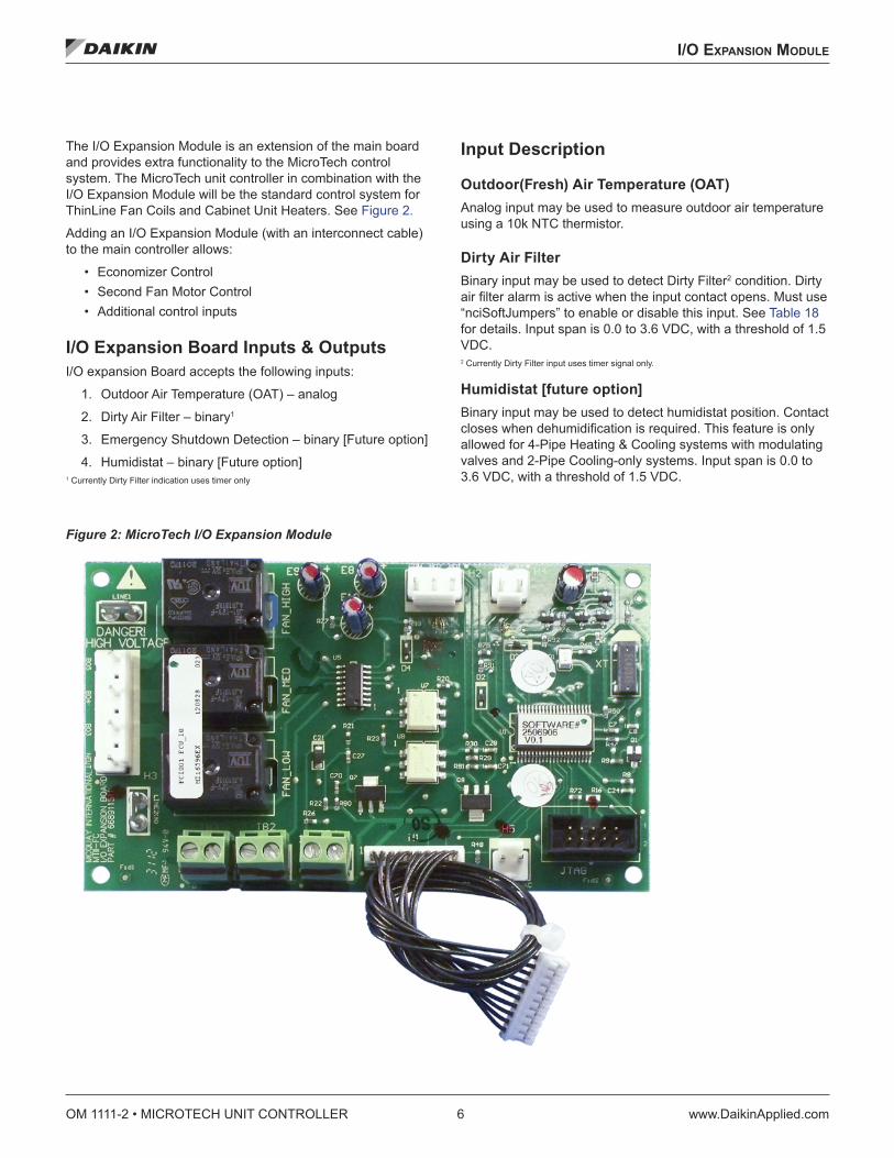
The I/O Expansion Module is an extension of the main board and provides extra functionality to the MicroTech control system . The MicroTech unit controller in combination with the I/O Expansion Module will be the standard control system for ThinLine Fan Coils and Cabinet Unit Heaters . See Figure 2 .
Adding an I/O Expansion Module (with an interconnect cable) to the main controller allows:
• Economizer Control• Second Fan Motor Control• Additional control inputs
I/O Expansion Board Inputs & OutputsI/O expansion Board accepts the following inputs:
1 . Outdoor Air Temperature (OAT) – analog
2 . Dirty Air Filter – binary1
3 . Emergency Shutdown Detection – binary [Future option]
4 . Humidistat – binary [Future option]1 Currently Dirty Filter indication uses timer only
Figure 2: MicroTech I/O Expansion Module
Input Description
Outdoor(Fresh) Air Temperature (OAT)Analog input may be used to measure outdoor air temperature using a 10k NTC thermistor .
Dirty Air FilterBinary input may be used to detect Dirty Filter2 condition . Dirty air filter alarm is active when the input contact opens. Must use “nciSoftJumpers” to enable or disable this input . See Table 18 for details . Input span is 0 .0 to 3 .6 VDC, with a threshold of 1 .5 VDC . 2 Currently Dirty Filter input uses timer signal only .
Humidistat [future option]Binary input may be used to detect humidistat position . Contact closes when dehumidification is required. This feature is only allowed for 4-Pipe Heating & Cooling systems with modulating valves and 2-Pipe Cooling-only systems . Input span is 0 .0 to 3 .6 VDC, with a threshold of 1 .5 VDC .
OM 1111-2 • MICROTECH UNIT CONTROLLER 6 www .DaikinApplied .com
I/o expansIon Module
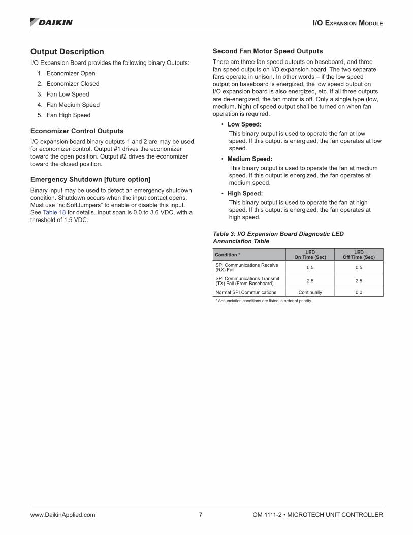
Output DescriptionI/O Expansion Board provides the following binary Outputs:
1 . Economizer Open
2 . Economizer Closed
3 . Fan Low Speed
4 . Fan Medium Speed
5 . Fan High Speed
Economizer Control OutputsI/O expansion board binary outputs 1 and 2 are may be used for economizer control . Output #1 drives the economizer toward the open position . Output #2 drives the economizer toward the closed position .
Emergency Shutdown [future option]Binary input may be used to detect an emergency shutdown condition . Shutdown occurs when the input contact opens . Must use “nciSoftJumpers” to enable or disable this input . See Table 18 for details . Input span is 0 .0 to 3 .6 VDC, with a threshold of 1 .5 VDC .
Second Fan Motor Speed OutputsThere are three fan speed outputs on baseboard, and three fan speed outputs on I/O expansion board . The two separate fans operate in unison . In other words – if the low speed output on baseboard is energized, the low speed output on I/O expansion board is also energized, etc . If all three outputs are de-energized, the fan motor is off . Only a single type (low, medium, high) of speed output shall be turned on when fan operation is required .
• Low Speed:This binary output is used to operate the fan at low speed . If this output is energized, the fan operates at low speed .
• Medium Speed:This binary output is used to operate the fan at medium speed . If this output is energized, the fan operates at medium speed .
• High Speed:This binary output is used to operate the fan at high speed . If this output is energized, the fan operates at high speed .
Table 3: I/O Expansion Board Diagnostic LED Annunciation Table
Condition * LED On Time (Sec)
LED Off Time (Sec)
SPI Communications Receive (RX) Fail 0 .5 0 .5
SPI Communications Transmit (TX) Fail (From Baseboard) 2 .5 2 .5
Normal SPI Communications Continually 0 .0
* Annunciation conditions are listed in order of priority .
I/o expansIon Module
www .DaikinApplied .com 7 OM 1111-2 • MICROTECH UNIT CONTROLLER
control Boards terMInals and connectors descrIptIons
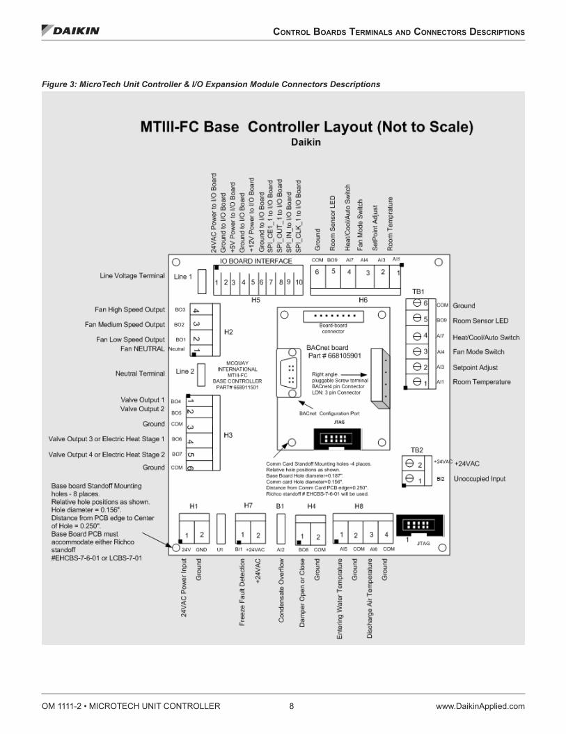
Figure 3: MicroTech Unit Controller & I/O Expansion Module Connectors Descriptions
OM 1111-2 • MICROTECH UNIT CONTROLLER 8 www .DaikinApplied .com
control Boards terMInals and connectors descrIptIons
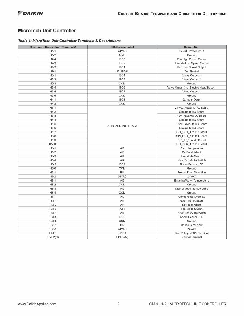
MicroTech Unit Controller
Table 4: MicroTech Unit Controller Terminals & DescriptionsBaseboard Connector – Terminal # Silk Screen Label Description
H1-1 24VAC 24VAC Power InputH1-2 GND GroundH2-4 BO3 Fan High Speed OutputH2-3 BO2 Fan Medium Speed OutputH2-2 BO1 Fan Low Speed OutputH2-1 NEUTRAL Fan NeutralH3-1 BO4 Valve Output 1H3-2 BO5 Valve Output 2H3-3 COM GroundH3-4 BO6 Valve Output 3 or Electric Heat Stage 1H3-5 BO7 Valve Output 4 H3-6 COM GroundH4-1 BO8 Damper OpenH4-2 COM GroundH5-1
I/O BOARD INTERFACE
24VAC Power to I/O BoardH5-2 Ground to I/O BoardH5-3 +5V Power to I/O BoardH5-4 Ground to I/O BoardH5-5 +12V Power to I/O BoardH5-6 Ground to I/O BoardH5-7 SPI_CE1_1 to I/O BoardH5-8 SPI_OUT_1 to I/O BoardH5-9 SPI_IN_1 to I/O Board
H5-10 SPI_CLK_1 to I/O BoardH6-1 AI1 Room TemperatureH6-2 AI3 SetPoint AdjustH6-3 AI4 Fan Mode SwitchH6-4 AI7 Heat/Cool/Auto SwitchH6-5 BO9 Room Sensor LEDH6-6 COM GroundH7-1 BI1 Freeze Fault DetectionH7-2 24VAC 24VACH8-1 AI5 Entering Water TemperatureH8-2 COM GroundH8-3 AI6 Discharge Air TemperatureH8-4 COM GroundB1 AI2 Condensate Overflow
TB1-1 AI1 Room TemperatureTB1-2 AI3 SetPoint AdjustTB1-3 A14 Fan Mode SwitchTB1-4 AI7 Heat/Cool/Auto SwitchTB1-5 BO9 Room Sensor LEDTB1-6 COM GroundTB2-1 BI2 Unoccupied inputTB2-2 24VAC 24VACLINE1 LINE1 Line Voltage/ECM Terminal
LINE2(N) LINE2(N) Neutral Terminal
control Boards terMInals and connectors descrIptIons
www .DaikinApplied .com 9 OM 1111-2 • MICROTECH UNIT CONTROLLER
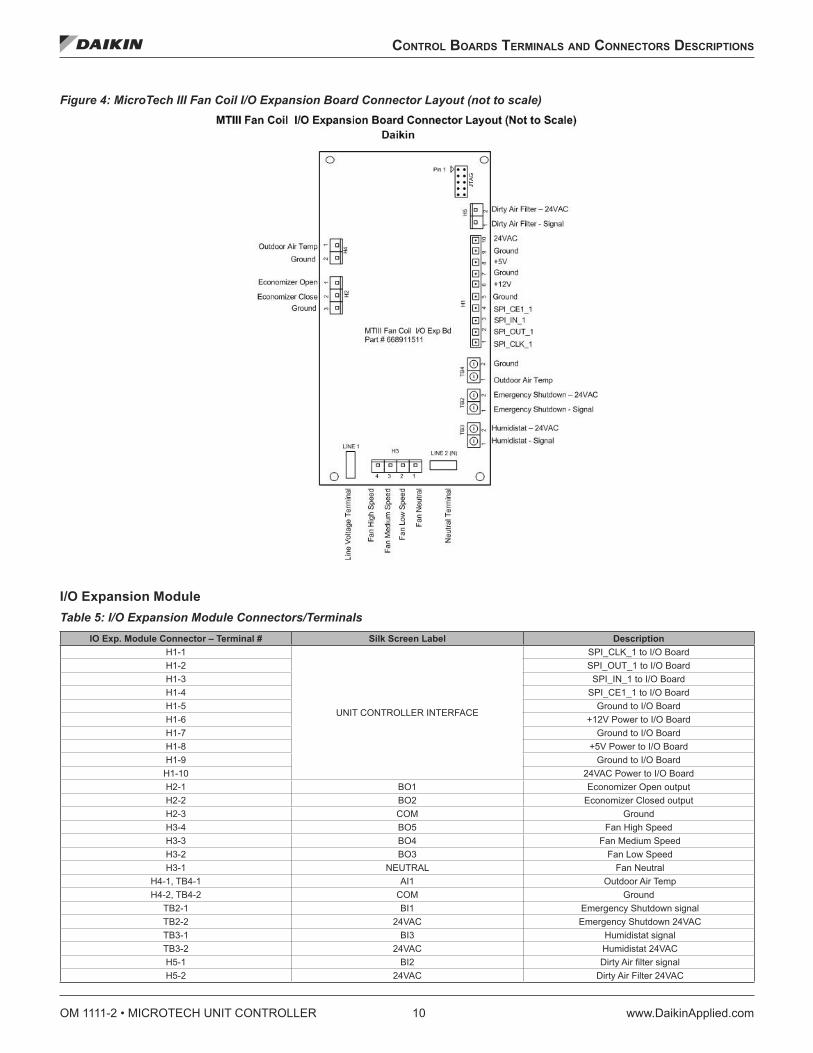
Figure 4: MicroTech III Fan Coil I/O Expansion Board Connector Layout (not to scale)
I/O Expansion ModuleTable 5: I/O Expansion Module Connectors/Terminals
IO Exp . Module Connector – Terminal # Silk Screen Label DescriptionH1-1
UNIT CONTROLLER INTERFACE
SPI_CLK_1 to I/O BoardH1-2 SPI_OUT_1 to I/O BoardH1-3 SPI_IN_1 to I/O Board H1-4 SPI_CE1_1 to I/O BoardH1-5 Ground to I/O Board H1-6 +12V Power to I/O BoardH1-7 Ground to I/O BoardH1-8 +5V Power to I/O BoardH1-9 Ground to I/O Board
H1-10 24VAC Power to I/O BoardH2-1 BO1 Economizer Open outputH2-2 BO2 Economizer Closed output H2-3 COM GroundH3-4 BO5 Fan High SpeedH3-3 BO4 Fan Medium SpeedH3-2 BO3 Fan Low SpeedH3-1 NEUTRAL Fan Neutral
H4-1, TB4-1 AI1 Outdoor Air TempH4-2, TB4-2 COM Ground
TB2-1 BI1 Emergency Shutdown signalTB2-2 24VAC Emergency Shutdown 24VACTB3-1 BI3 Humidistat signalTB3-2 24VAC Humidistat 24VACH5-1 BI2 Dirty Air filter signalH5-2 24VAC Dirty Air Filter 24VAC
OM 1111-2 • MICROTECH UNIT CONTROLLER 10 www .DaikinApplied .com
control Boards terMInals and connectors descrIptIons
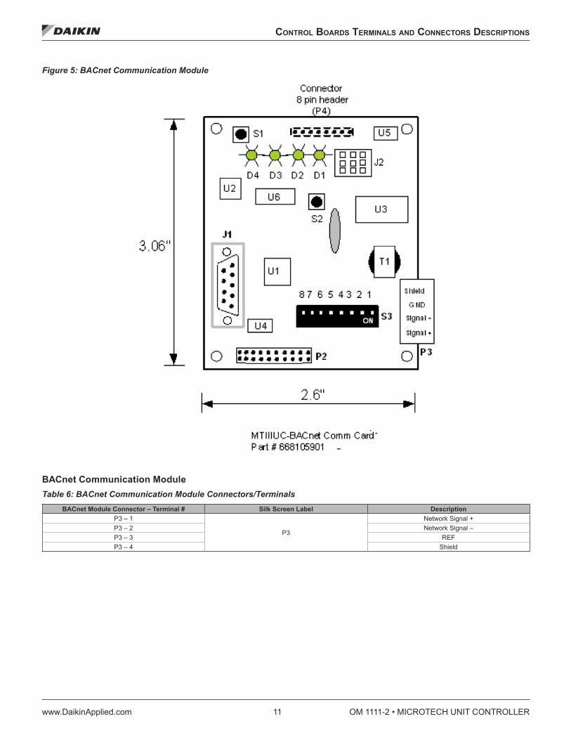
Figure 5: BACnet Communication Module
BACnet Communication ModuleTable 6: BACnet Communication Module Connectors/Terminals
BACnet Module Connector – Terminal # Silk Screen Label DescriptionP3 – 1
P3
Network Signal +P3 – 2 Network Signal –P3 – 3 REFP3 – 4 Shield
control Boards terMInals and connectors descrIptIons
www .DaikinApplied .com 11 OM 1111-2 • MICROTECH UNIT CONTROLLER
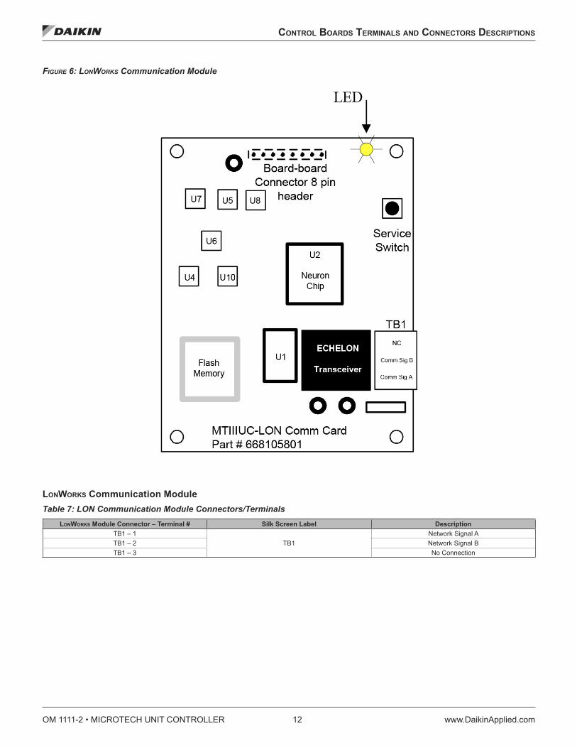
Figure 6: LonWorks Communication Module
lonWorks Communication Module Table 7: LON Communication Module Connectors/Terminals
lonWorks Module Connector – Terminal # Silk Screen Label DescriptionTB1 – 1
TB1Network Signal A
TB1 – 2 Network Signal BTB1 – 3 No Connection
OM 1111-2 • MICROTECH UNIT CONTROLLER 12 www .DaikinApplied .com
control Boards terMInals and connectors descrIptIons
Fan coIl/caBInet unIt heater unIt control
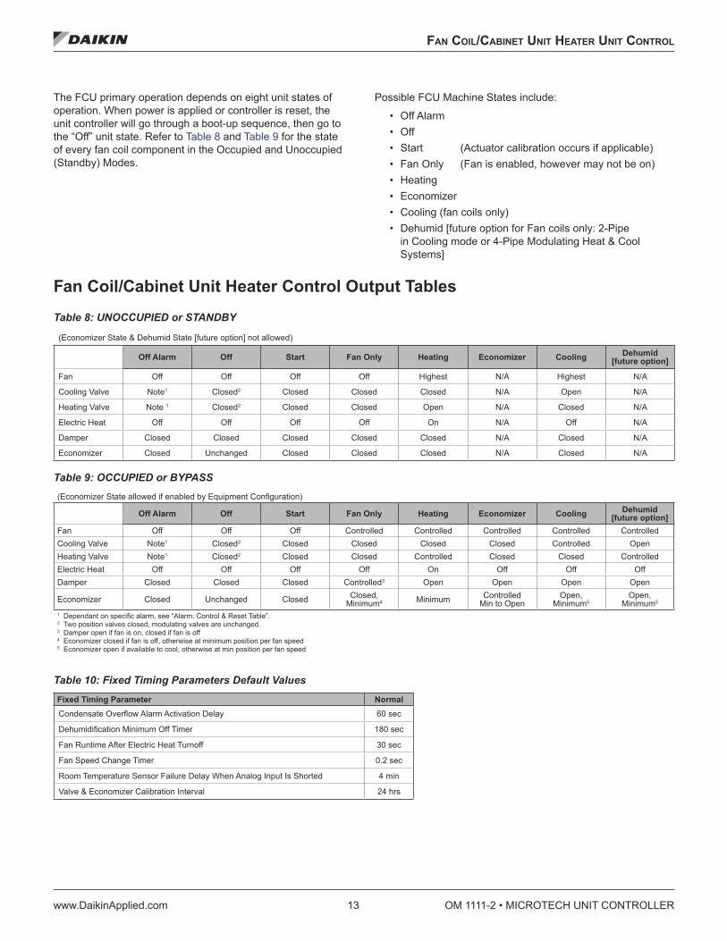
The FCU primary operation depends on eight unit states of operation . When power is applied or controller is reset, the unit controller will go through a boot-up sequence, then go to the “Off” unit state . Refer to Table 8 and Table 9 for the state of every fan coil component in the Occupied and Unoccupied (Standby) Modes .
Possible FCU Machine States include:
• Off Alarm• Off• Start (Actuator calibration occurs if applicable)• Fan Only (Fan is enabled, however may not be on)• Heating• Economizer• Cooling (fan coils only)• Dehumid [future option for Fan coils only: 2-Pipe
in Cooling mode or 4-Pipe Modulating Heat & Cool Systems]
Fan Coil/Cabinet Unit Heater Control Output Tables
Table 8: UNOCCUPIED or STANDBY
(Economizer State & Dehumid State [future option] not allowed)
Off Alarm Off Start Fan Only Heating Economizer Cooling Dehumid [future option]
Fan Off Off Off Off Highest N/A Highest N/A
Cooling Valve Note1 Closed2 Closed Closed Closed N/A Open N/A
Heating Valve Note 1 Closed2 Closed Closed Open N/A Closed N/A
Electric Heat Off Off Off Off On N/A Off N/A
Damper Closed Closed Closed Closed Closed N/A Closed N/A
Economizer Closed Unchanged Closed Closed Closed N/A Closed N/A
Table 9: OCCUPIED or BYPASS (Economizer State allowed if enabled by Equipment Configuration)
Off Alarm Off Start Fan Only Heating Economizer Cooling Dehumid [future option]
Fan Off Off Off Controlled Controlled Controlled Controlled ControlledCooling Valve Note1 Closed2 Closed Closed Closed Closed Controlled OpenHeating Valve Note1 Closed2 Closed Closed Controlled Closed Closed ControlledElectric Heat Off Off Off Off On Off Off OffDamper Closed Closed Closed Controlled3 Open Open Open Open
Economizer Closed Unchanged Closed Closed, Minimum4 Minimum Controlled
Min to OpenOpen,
Minimum5Open,
Minimum5
1 Dependant on specific alarm, see “Alarm: Control & Reset Table”.2 Two position valves closed, modulating valves are unchanged .3 Damper open if fan is on, closed if fan is off4 Economizer closed if fan is off, otherwise at minimum position per fan speed5 Economizer open if available to cool, otherwise at min position per fan speed
Table 10: Fixed Timing Parameters Default ValuesFixed Timing Parameter NormalCondensate Overflow Alarm Activation Delay 60 sec
Dehumidification Minimum Off Timer 180 sec
Fan Runtime After Electric Heat Turnoff 30 sec
Fan Speed Change Timer 0 .2 sec
Room Temperature Sensor Failure Delay When Analog Input Is Shorted 4 min
Valve & Economizer Calibration Interval 24 hrs
Fan coIl/caBInet unIt heater unIt control
www .DaikinApplied .com 13 OM 1111-2 • MICROTECH UNIT CONTROLLER
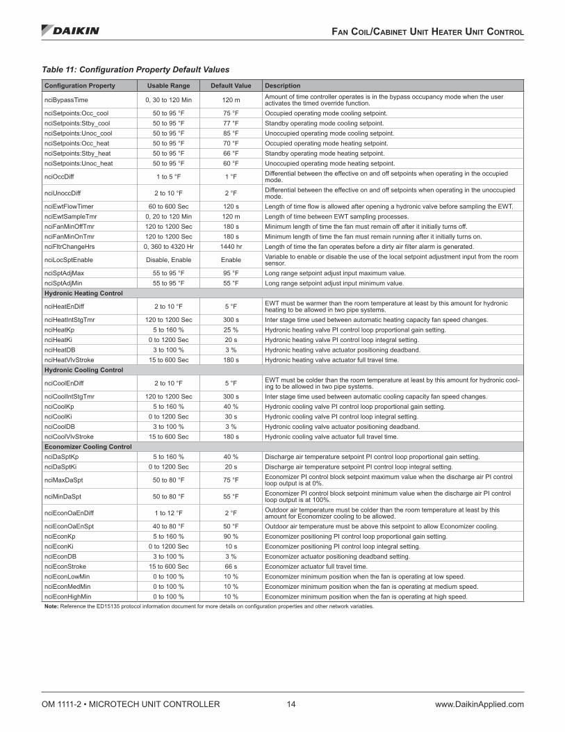
Table 11: Configuration Property Default Values
Configuration Property Usable Range Default Value Description
nciBypassTime 0, 30 to 120 Min 120 m Amount of time controller operates is in the bypass occupancy mode when the user activates the timed override function .
nciSetpoints:Occ_cool 50 to 95 °F 75 °F Occupied operating mode cooling setpoint .nciSetpoints:Stby_cool 50 to 95 °F 77 °F Standby operating mode cooling setpoint .nciSetpoints:Unoc_cool 50 to 95 °F 85 °F Unoccupied operating mode cooling setpoint .nciSetpoints:Occ_heat 50 to 95 °F 70 °F Occupied operating mode heating setpoint .nciSetpoints:Stby_heat 50 to 95 °F 66 °F Standby operating mode heating setpoint .nciSetpoints:Unoc_heat 50 to 95 °F 60 °F Unoccupied operating mode heating setpoint .
nciOccDiff 1 to 5 °F 1 °F Differential between the effective on and off setpoints when operating in the occupied mode .
nciUnoccDiff 2 to 10 °F 2 °F Differential between the effective on and off setpoints when operating in the unoccupied mode .
nciEwtFlowTimer 60 to 600 Sec 120 s Length of time flow is allowed after opening a hydronic valve before sampling the EWT.nciEwtSampleTmr 0, 20 to 120 Min 120 m Length of time between EWT sampling processes .nciFanMinOffTmr 120 to 1200 Sec 180 s Minimum length of time the fan must remain off after it initially turns off .nciFanMinOnTmr 120 to 1200 Sec 180 s Minimum length of time the fan must remain running after it initially turns on .nciFltrChangeHrs 0, 360 to 4320 Hr 1440 hr Length of time the fan operates before a dirty air filter alarm is generated.
nciLocSptEnable Disable, Enable Enable Variable to enable or disable the use of the local setpoint adjustment input from the room sensor .
nciSptAdjMax 55 to 95 °F 95 °F Long range setpoint adjust input maximum value .nciSptAdjMin 55 to 95 °F 55 °F Long range setpoint adjust input minimum value .Hydronic Heating Control
nciHeatEnDiff 2 to 10 °F 5 °F EWT must be warmer than the room temperature at least by this amount for hydronic heating to be allowed in two pipe systems .
nciHeatIntStgTmr 120 to 1200 Sec 300 s Inter stage time used between automatic heating capacity fan speed changes .nciHeatKp 5 to 160 % 25 % Hydronic heating valve PI control loop proportional gain setting .nciHeatKi 0 to 1200 Sec 20 s Hydronic heating valve PI control loop integral setting .nciHeatDB 3 to 100 % 3 % Hydronic heating valve actuator positioning deadband .nciHeatVlvStroke 15 to 600 Sec 180 s Hydronic heating valve actuator full travel time .Hydronic Cooling Control
nciCoolEnDiff 2 to 10 °F 5 °F EWT must be colder than the room temperature at least by this amount for hydronic cool-ing to be allowed in two pipe systems .
nciCoolIntStgTmr 120 to 1200 Sec 300 s Inter stage time used between automatic cooling capacity fan speed changes .nciCoolKp 5 to 160 % 40 % Hydronic cooling valve PI control loop proportional gain setting .nciCoolKi 0 to 1200 Sec 30 s Hydronic cooling valve PI control loop integral setting .nciCoolDB 3 to 100 % 3 % Hydronic cooling valve actuator positioning deadband .nciCoolVlvStroke 15 to 600 Sec 180 s Hydronic cooling valve actuator full travel time .Economizer Cooling ControlnciDaSptKp 5 to 160 % 40 % Discharge air temperature setpoint PI control loop proportional gain setting .nciDaSptKi 0 to 1200 Sec 20 s Discharge air temperature setpoint PI control loop integral setting .
nciMaxDaSpt 50 to 80 °F 75 °F Economizer PI control block setpoint maximum value when the discharge air PI control loop output is at 0% .
nciMinDaSpt 50 to 80 °F 55 °F Economizer PI control block setpoint minimum value when the discharge air PI control loop output is at 100% .
nciEconOaEnDiff 1 to 12 °F 2 °F Outdoor air temperature must be colder than the room temperature at least by this amount for Economizer cooling to be allowed .
nciEconOaEnSpt 40 to 80 °F 50 °F Outdoor air temperature must be above this setpoint to allow Economizer cooling .nciEconKp 5 to 160 % 90 % Economizer positioning PI control loop proportional gain setting .nciEconKi 0 to 1200 Sec 10 s Economizer positioning PI control loop integral setting .nciEconDB 3 to 100 % 3 % Economizer actuator positioning deadband setting .nciEconStroke 15 to 600 Sec 66 s Economizer actuator full travel time .nciEconLowMin 0 to 100 % 10 % Economizer minimum position when the fan is operating at low speed .nciEconMedMin 0 to 100 % 10 % Economizer minimum position when the fan is operating at medium speed .nciEconHighMin 0 to 100 % 10 % Economizer minimum position when the fan is operating at high speed .Note: Reference the ED15135 protocol information document for more details on configuration properties and other network variables.
OM 1111-2 • MICROTECH UNIT CONTROLLER 14 www .DaikinApplied .com
Fan coIl/caBInet unIt heater unIt control
Operating Modes
Start-up The unit will not operate until all the inputs and safety controls are checked for normal conditions .
General Sequences of Operation
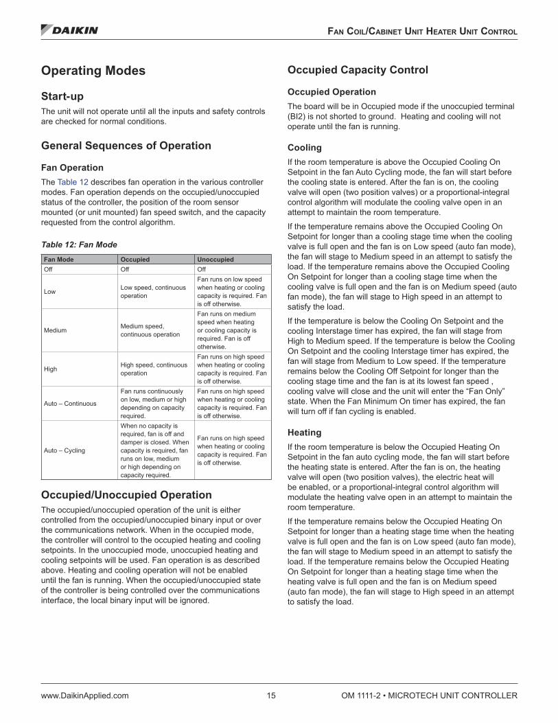
Fan Operation The Table 12 describes fan operation in the various controller modes . Fan operation depends on the occupied/unoccupied status of the controller, the position of the room sensor mounted (or unit mounted) fan speed switch, and the capacity requested from the control algorithm .
Table 12: Fan ModeFan Mode Occupied UnoccupiedOff Off Off
Low Low speed, continuous operation
Fan runs on low speed when heating or cooling capacity is required . Fan is off otherwise .
Medium Medium speed, continuous operation
Fan runs on medium speed when heating or cooling capacity is required . Fan is off otherwise .
High High speed, continuous operation
Fan runs on high speed when heating or cooling capacity is required . Fan is off otherwise .
Auto – Continuous
Fan runs continuously on low, medium or high depending on capacity required .
Fan runs on high speed when heating or cooling capacity is required . Fan is off otherwise .
Auto – Cycling
When no capacity is required, fan is off and damper is closed . When capacity is required, fan runs on low, medium or high depending on capacity required .
Fan runs on high speed when heating or cooling capacity is required . Fan is off otherwise .
Occupied/Unoccupied OperationThe occupied/unoccupied operation of the unit is either controlled from the occupied/unoccupied binary input or over the communications network . When in the occupied mode, the controller will control to the occupied heating and cooling setpoints . In the unoccupied mode, unoccupied heating and cooling setpoints will be used . Fan operation is as described above . Heating and cooling operation will not be enabled until the fan is running . When the occupied/unoccupied state of the controller is being controlled over the communications interface, the local binary input will be ignored .
Occupied Capacity Control
Occupied OperationThe board will be in Occupied mode if the unoccupied terminal (BI2) is not shorted to ground . Heating and cooling will not operate until the fan is running .
Cooling If the room temperature is above the Occupied Cooling On Setpoint in the fan Auto Cycling mode, the fan will start before the cooling state is entered . After the fan is on, the cooling valve will open (two position valves) or a proportional-integral control algorithm will modulate the cooling valve open in an attempt to maintain the room temperature .
If the temperature remains above the Occupied Cooling On Setpoint for longer than a cooling stage time when the cooling valve is full open and the fan is on Low speed (auto fan mode), the fan will stage to Medium speed in an attempt to satisfy the load . If the temperature remains above the Occupied Cooling On Setpoint for longer than a cooling stage time when the cooling valve is full open and the fan is on Medium speed (auto fan mode), the fan will stage to High speed in an attempt to satisfy the load .
If the temperature is below the Cooling On Setpoint and the cooling Interstage timer has expired, the fan will stage from High to Medium speed . If the temperature is below the Cooling On Setpoint and the cooling Interstage timer has expired, the fan will stage from Medium to Low speed . If the temperature remains below the Cooling Off Setpoint for longer than the cooling stage time and the fan is at its lowest fan speed , cooling valve will close and the unit will enter the “Fan Only” state . When the Fan Minimum On timer has expired, the fan will turn off if fan cycling is enabled .
HeatingIf the room temperature is below the Occupied Heating On Setpoint in the fan auto cycling mode, the fan will start before the heating state is entered . After the fan is on, the heating valve will open (two position valves), the electric heat will be enabled, or a proportional-integral control algorithm will modulate the heating valve open in an attempt to maintain the room temperature .
If the temperature remains below the Occupied Heating On Setpoint for longer than a heating stage time when the heating valve is full open and the fan is on Low speed (auto fan mode), the fan will stage to Medium speed in an attempt to satisfy the load . If the temperature remains below the Occupied Heating On Setpoint for longer than a heating stage time when the heating valve is full open and the fan is on Medium speed (auto fan mode), the fan will stage to High speed in an attempt to satisfy the load .
Fan coIl/caBInet unIt heater unIt control
www .DaikinApplied .com 15 OM 1111-2 • MICROTECH UNIT CONTROLLER
If the temperature is above the Heating On Setpoint and the heating Interstage timer has expired, the fan will stage from High to Medium speed . If the temperature is above the Heating On setpoint and the heating Interstage timer has expired, the fan will stage from Medium to Low speed . If the temperature remains above the Heating Off Setpoint for longer than the heating stage time and the fan is at its lowest fan speed the heating valve will close, electric heat will shut off, and the unit will enter the Fan Only state . When the Fan Minimum On and the Fan On After Electric Heat timers have expired, the fan will turn off if fan cycling is enabled .
Unoccupied Capacity Control
Cooling When the room temperature rises above the Unoccupied Cooling On Setpoint, the fan will start in High speed and the cooling valve will fully open in an attempt to maintain room temperature. When the temperature is satisfied (temperature drops below the Unoccupied Cooling On Setpoint minus the unoccupied differential) and the cooling Interstage timer has expired, the valve will first close and then the fan will shut off.
HeatingWhen the room temperature falls below the Unoccupied Heating On Setpoint, the fan will start in High speed and the heating valve will fully open (or the electric heat will be enabled) in an attempt to maintain room temperature . When the temperature is satisfied (temperature rises above the Unoccupied Heating On Setpoint plus the unoccupied differential) and the heating Interstage timer has expired, the valve will first close, electric heat will shut off and then the fan will shut off .
Dehumidification Operation [future option]This fan coil state is allowed for: 2-Pipe in Cooling only or 4-Pipe Modulating Heating & Cooling systems; and controller must be in the occupied or bypass mode . Modulating Cooling valve is fully open . Electric heat is off . Fresh Air Damper (if available) is open . Economizer, if available, will be fully open, otherwise at minimum position based on fan speed .
2-Pipe Cooling Only System:• Fan is on at lowest available speed .• Heating valve is non-existent .• Dehumidification is only allowed when the effective space
temperature is greater than the effective heating on setpoint, and becomes disabled when space temperature drops below the effective heating on setpoint minus a 2°F fixed differential.
4-Pipe Modulating Heating & Cooling System:• Fan is on at speed determined by capacity and effective
fan mode/speed .• Heating valve is controlled .
General OperationUnit status will change to the “Fan Only” state if all of the following conditions exist:
• Dehumidification isn’t required or is not available, heating or cooling capacity becomes required .
• The cooling valve has been driven closed .• The 4-pipe system heating valve has been driven closed .• Fan is running at the lowest possible speed based on:
selected occupancy and fan mode/speed switch setting .
Dehumid State Notes• For dehumidification availability definition, see
“Miscellaneous Control Definitions section”.• When leaving “Dehumid” state, the 180 second fixed
“dehumidification minimum off” timer will be started. This prevents returning back to the “Dehumid” state too soon .
Total Electric Heat mode (2-pipe Cooling systems only) On an initial call for heating:
1 . The fan will start at Low speed in “Fan Only” state
2 . Unit enters Heating state, electric heat is energized, and heating Interstage timer is started
3 . If Heating Interstage Countdown Timer has expired and room temperature is below the Heating On Setpoint, fan speed will be changed from Low to Medium, and Heating Interstage Countdown Timer is started again .
4 . If Heating Interstage Countdown Timer has expired and room temperature is below the Heating On Setpoint, fan speed will be changed from Medium to High, and Heating Interstage Countdown Timer is started again .
Once room temperature reaches the Heating On Setpoint the fan will be run at Medium and Low speed with Interstage Countdown Timer started each time the fan speed is changed . When the room setpoint conditions are satisfied, electric heat will be de-energized and the fan will continue to operate at its “fan only” setting when enabled, for continuous fan operation . If fan cycling is enabled, the fan will turn off after 30 seconds once room setpoint conditions are satisfied.
OM 1111-2 • MICROTECH UNIT CONTROLLER 16 www .DaikinApplied .com
Fan coIl/caBInet unIt heater unIt control
Supplemental (Intermediate) Electric Heat mode [for 2-pipe Cooling/Heating systems only] On an initial call for heating, the controller will open the water valve for Flow Timer” to check for appropriate entering water temperature . Once the water valve is 100% open, a 120-second (default setting) flow timer will start and flow allowed . When timer has expired and if water temperature is colder than required for hydronic heating the control valve will fully closed, fan started and electric heater energized . The rest of the operation will run as described in paragraph Total Electric heat above exclusively using electric heat (EWT is not sampled for systems with Total Electric Heat) .
Proportional–Integral Control ParametersAssociated with each Proportional-Integral (PI) control loop are three adjustable parameters: Proportional Gain (Kp), Integral Time (Ki), and Deadband (DB) . When the fan coil unit (FCU) is properly sized for the space, the factory settings for these parameters will provide the best control action for all the various operating scenarios .
PI Control AlgorithmThe PI control algorithm calculates the desired actuator output, and ranges from 0 to 100% .
Definitions:• Error: Value is calculated one of two ways depending on
the PI blocks fixed action type.Direct Acting Block: Error = (PV – SP)
Reverse Acting Block: Error = (SP – PV)
• Process Variable (PV): Measured analog input reading .• Sample Time: Scan rate of the PI control blocks, which is
an internal fixed value of 10 seconds.• Sum of Errors: Summation, or total, of all past errors .
Output Formula:PI Output = (Kp × Error) + ((Sample Time × Sum of Past Errors) / Ki)
If field problems arise, first ensure these parameters are set back to the factory default settings . If adjustment is required, only make small adjustments to one parameter at a time . After each adjustment, induce an instantaneous error into the PI algorithm and allow enough time for the system to stabilize before making any further modifications. If you do not have the means to graph the process variable performance, record the actual measured value and set point for the duration of the test and then plot the results using a spreadsheet to determine the correct action to take .
Proportional GainThe proportional gain, or proportional action, causes the controlled output to change in proportion to the magnitude of the present error amount . Error is the difference between the sensors present value and the set point . When the Kp setting is too low, the process variable (PV) response will change too slowly . When the Kp setting is too high, the process variable response will excessively overshoot and possibly oscillate around the setpoint (SP) . If faster system response is desired increase the proportional gain (Kp) setting . Use caution not to become too aggressive with the proportional gain setting to avoid causing system instability .
Integral TimeThe integral time, or integral action, accumulates the error amounts and causes the controlled output to approach the set point over time in an attempt to eliminate any system offset . The smaller the integral (Ki) setting, the more the integral will affect the process under control . When the Ki setting is too low, the process variable (PV) will oscillate around the setpoint . When the Ki setting is too high, the process variable will never reach the setpoint .
DeadbandThe deadband parameter serves two main purposes . First deadband prevents the actuator from constantly hunting or overcorrecting, and secondly ensures the actuator physically moves every time a new positioning command is given . Deadband will prevent small output changes from modifying the actuator position. When the deadband configuration property is set to 3%, the PI control output adjustment must exceed plus or minus 1 .5%, or the actuator position will not be changed .
CAUTIONAdjusting PI parameters can cause erratic unit operation, and potentially damage the equipment .PI control parameters must only be adjusted by trained personnel having a complete understanding of how these parameters affect system operation . Generally these parameters do not need to be adjusted from the factory settings .
Fan coIl/caBInet unIt heater unIt control
www .DaikinApplied .com 17 OM 1111-2 • MICROTECH UNIT CONTROLLER
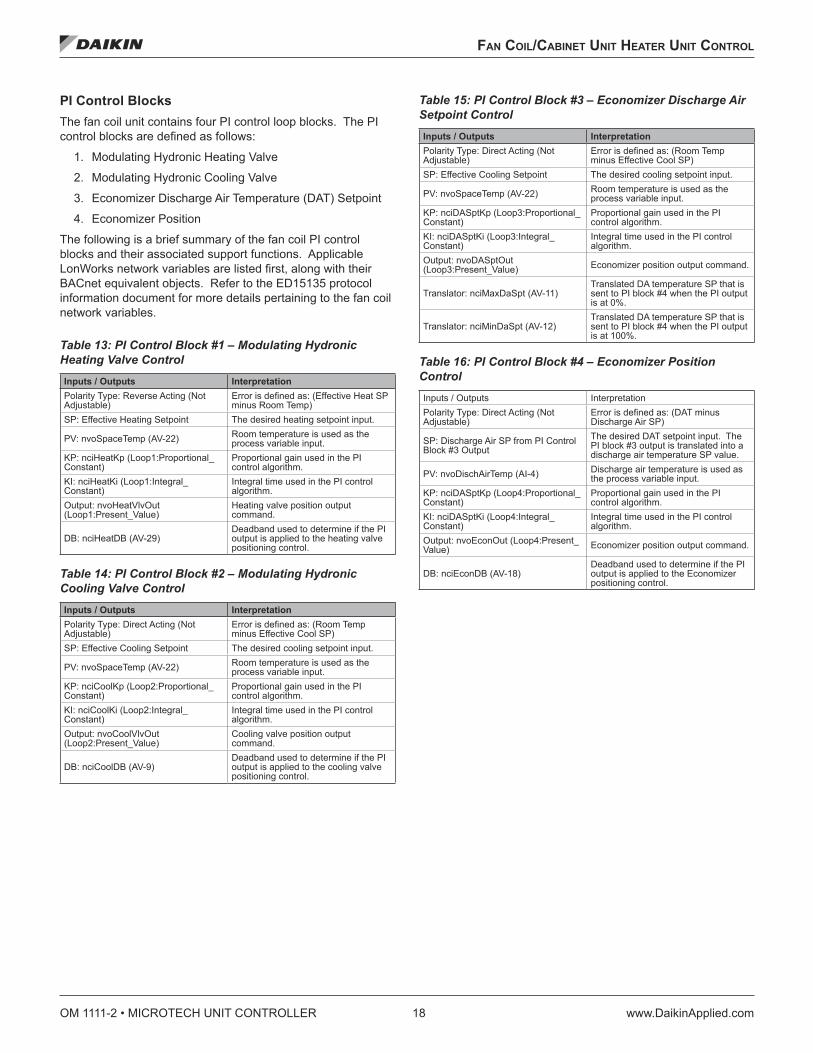
PI Control BlocksThe fan coil unit contains four PI control loop blocks . The PI control blocks are defined as follows:
1 . Modulating Hydronic Heating Valve
2 . Modulating Hydronic Cooling Valve
3 . Economizer Discharge Air Temperature (DAT) Setpoint
4 . Economizer Position
The following is a brief summary of the fan coil PI control blocks and their associated support functions . Applicable LonWorks network variables are listed first, along with their BACnet equivalent objects . Refer to the ED15135 protocol information document for more details pertaining to the fan coil network variables .
Table 13: PI Control Block #1 – Modulating Hydronic Heating Valve ControlInputs / Outputs InterpretationPolarity Type: Reverse Acting (Not Adjustable)
Error is defined as: (Effective Heat SP minus Room Temp)
SP: Effective Heating Setpoint The desired heating setpoint input .
PV: nvoSpaceTemp (AV-22) Room temperature is used as the process variable input .
KP: nciHeatKp (Loop1:Proportional_Constant)
Proportional gain used in the PI control algorithm .
KI: nciHeatKi (Loop1:Integral_Constant)
Integral time used in the PI control algorithm .
Output: nvoHeatVlvOut (Loop1:Present_Value)
Heating valve position output command .
DB: nciHeatDB (AV-29)Deadband used to determine if the PI output is applied to the heating valve positioning control .
Table 14: PI Control Block #2 – Modulating Hydronic Cooling Valve ControlInputs / Outputs InterpretationPolarity Type: Direct Acting (Not Adjustable)
Error is defined as: (Room Temp minus Effective Cool SP)
SP: Effective Cooling Setpoint The desired cooling setpoint input .
PV: nvoSpaceTemp (AV-22) Room temperature is used as the process variable input .
KP: nciCoolKp (Loop2:Proportional_Constant)
Proportional gain used in the PI control algorithm .
KI: nciCoolKi (Loop2:Integral_Constant)
Integral time used in the PI control algorithm .
Output: nvoCoolVlvOut (Loop2:Present_Value)
Cooling valve position output command .
DB: nciCoolDB (AV-9)Deadband used to determine if the PI output is applied to the cooling valve positioning control .
Table 15: PI Control Block #3 – Economizer Discharge Air Setpoint ControlInputs / Outputs InterpretationPolarity Type: Direct Acting (Not Adjustable)
Error is defined as: (Room Temp minus Effective Cool SP)
SP: Effective Cooling Setpoint The desired cooling setpoint input .
PV: nvoSpaceTemp (AV-22) Room temperature is used as the process variable input .
KP: nciDASptKp (Loop3:Proportional_Constant)
Proportional gain used in the PI control algorithm .
KI: nciDASptKi (Loop3:Integral_Constant)
Integral time used in the PI control algorithm .
Output: nvoDASptOut (Loop3:Present_Value) Economizer position output command .
Translator: nciMaxDaSpt (AV-11)Translated DA temperature SP that is sent to PI block #4 when the PI output is at 0% .
Translator: nciMinDaSpt (AV-12)Translated DA temperature SP that is sent to PI block #4 when the PI output is at 100% .
Table 16: PI Control Block #4 – Economizer Position ControlInputs / Outputs InterpretationPolarity Type: Direct Acting (Not Adjustable)
Error is defined as: (DAT minus Discharge Air SP)
SP: Discharge Air SP from PI Control Block #3 Output
The desired DAT setpoint input . The PI block #3 output is translated into a discharge air temperature SP value .
PV: nvoDischAirTemp (AI-4) Discharge air temperature is used as the process variable input .
KP: nciDASptKp (Loop4:Proportional_Constant)
Proportional gain used in the PI control algorithm .
KI: nciDASptKi (Loop4:Integral_Constant)
Integral time used in the PI control algorithm .
Output: nvoEconOut (Loop4:Present_Value) Economizer position output command .
DB: nciEconDB (AV-18)Deadband used to determine if the PI output is applied to the Economizer positioning control .
OM 1111-2 • MICROTECH UNIT CONTROLLER 18 www .DaikinApplied .com
Fan coIl/caBInet unIt heater unIt control
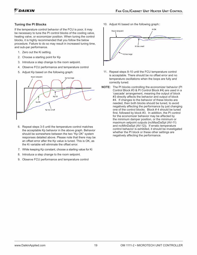
Tuning the PI BlocksIf the temperature control behavior of the FCU is poor, it may be necessary to tune the PI control blocks of the cooling valve, heating valve, or economizer position . When tuning the control blocks, it is highly recommended that you follow the below procedure . Failure to do so may result in increased tuning time, and sub-par performance .
1 . Zero out the Ki setting .
2 . Choose a starting point for Kp
3 . Introduce a step change to the room setpoint .
4 . Observe FCU performance and temperature control
5 . Adjust Kp based on the following graph:
6 . Repeat steps 3-5 until the temperature control matches the acceptable Kp behavior in the above graph . Behavior should be somewhere between the two “Kp OK” system responses detailed above . Please note that there may be an offset error after the Kp value is tuned . This is OK, as the Ki variable will eliminate the offset error .
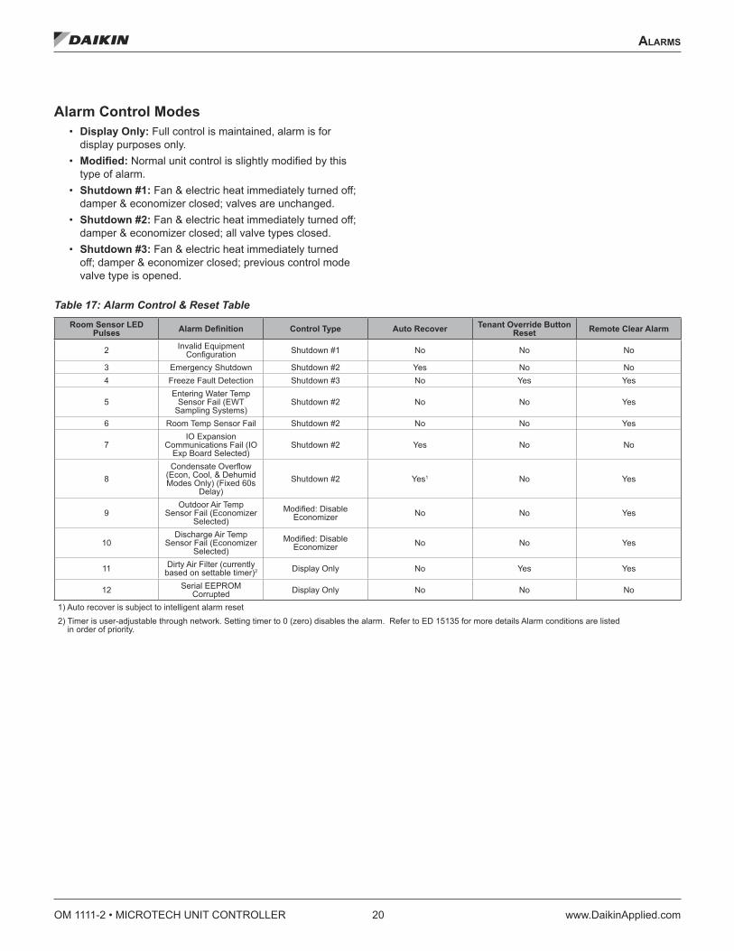
7 . While keeping Kp constant, choose a starting value for Ki
8 . Introduce a step change to the room setpoint .
9 . Observe FCU performance and temperature control
10 . Adjust Ki based on the following graph::
11 . Repeat steps 8-10 until the FCU temperature control is acceptable . There should be no offset error and no temperature oscillations when the loops are fully and correctly tuned .
NOTE: The PI blocks controlling the economizer behavior (PI Control Block #3 & PI Control Block #4) are used in a ‘cascade’ arrangement, meaning the output of block #3 directly affects the behavior and output of block #4 . If changes to the behavior of these blocks are needed, then both blocks should be tuned, to avoid negatively affecting the performance by just changing one of the control blocks . Block # 4 should be tuned first, followed by block #3. In addition, the PI control for the economizer behavior may be affected by the minimum damper position, or the minimum or maximum setpoint outputs (nciMaxDaSpt (AV-11) and nciMinDaSpt (AV-12)) . If erratic temperature control behavior is exhibited, it should be investigated whether the PI block or these other settings are negatively affecting the performance .
Fan coIl/caBInet unIt heater unIt control
www .DaikinApplied .com 19 OM 1111-2 • MICROTECH UNIT CONTROLLER
alarMs
Alarm Control Modes• Display Only: Full control is maintained, alarm is for
display purposes only .• Modified: Normal unit control is slightly modified by this
type of alarm .• Shutdown #1: Fan & electric heat immediately turned off;
damper & economizer closed; valves are unchanged .• Shutdown #2: Fan & electric heat immediately turned off;
damper & economizer closed; all valve types closed .• Shutdown #3: Fan & electric heat immediately turned
off; damper & economizer closed; previous control mode valve type is opened .
Table 17: Alarm Control & Reset TableRoom Sensor LED
Pulses Alarm Definition Control Type Auto Recover Tenant Override Button Reset Remote Clear Alarm
2 Invalid Equipment Configuration Shutdown #1 No No No
3 Emergency Shutdown Shutdown #2 Yes No No4 Freeze Fault Detection Shutdown #3 No Yes Yes
5 Entering Water Temp
Sensor Fail (EWT Sampling Systems)
Shutdown #2 No No Yes
6 Room Temp Sensor Fail Shutdown #2 No No Yes
7 IO Expansion
Communications Fail (IO Exp Board Selected)
Shutdown #2 Yes No No
8 Condensate Overflow
(Econ, Cool, & Dehumid Modes Only) (Fixed 60s
Delay)Shutdown #2 Yes1 No Yes
9 Outdoor Air Temp
Sensor Fail (Economizer Selected)
Modified: Disable Economizer No No Yes
10Discharge Air Temp
Sensor Fail (Economizer Selected)
Modified: Disable Economizer No No Yes
11 Dirty Air Filter (currently based on settable timer)2 Display Only No Yes Yes
12 Serial EEPROM Corrupted Display Only No No No
1) Auto recover is subject to intelligent alarm reset 2) Timer is user-adjustable through network . Setting timer to 0 (zero) disables the alarm . Refer to ED 15135 for more details Alarm conditions are listed
in order of priority .
OM 1111-2 • MICROTECH UNIT CONTROLLER 20 www .DaikinApplied .com
alarMs
MIscellaneous control deFInItIons
Heating Capacity RequiredHeating capacity is considered “required” when Effective Space Temperature (nvoSpaceTemp) goes below calculated effective heating on setpoint; then becomes “not required” when the temperature goes above calculated effective heating off setpoint .
Cooling Capacity RequiredCooling capacity is considered “required” when Effective Space Temperature (nvoSpaceTemp) goes above calculated effective cooling on setpoint; then becomes “not required” when the temperature goes below calculated effective cooling off setpoint . Economizer state, if available, has priority over cooling state .
Dehumidification Required Dehumidification is considered “required” when the humidistat binary input is active, and no heating or cooling capacities are required . Also in 2-Pipe cooling only systems, the effective space temperature (nvoSpaceTemp) must be greater than the effective heating on setpoint for dehumidification to be allowed
Fan AvailabilityFan is considered available if all of the following conditions exist:
• Equipment configuration software jumper (nciSoftJumpers) has selected a valid fan speed type .
• Remote application mode (nviApplicMode) is not set to “Off” .
• Local hardwired fan mode/speed switch (nvoFanModeSpdSw) is not set to “Off” .
• The “fan minimum off” timer has expired .
Dehumidification Availability Dehumidification is considered available if all of the following conditions exist:
• Equipment configuration software jumper (nciSoftJumpers) states that a 2-Pipe hydronic cooling only without electric heat; or 4-Pipe hydronic modulating heating and cooling system is selected in the fan coil unit .
• For 2-Pipe Cooling only systems the Effective Space Temperature (nvoSpaceTemp) must be above the Effective Heating On setpoint .
• Remote application mode (nviApplicMode) is set to “Auto”, “Dehumid”, or “Null” .
• Local Heat/Cool/Auto mode switch (nvoHeatCoolAuto) is set to “Auto” or “Cool” .
• I/O expansion board communications is not failed .• Effective occupancy (nvoEffectOccup) is occupied or
bypass mode .• The fixed “dehumidification minimum off” timer has
expired .• Condensate overflow alarm is not active.
Economizer AvailabilityEconomizer is considered available if all of the following conditions exist:
• Equipment configuration software jumper (nciSoftJumpers) states economizer is present in the fan coil unit .
• Remote application mode (nviApplicMode) is set to “Auto”, “Economy”, or “Null” .
• Local Heat/Cool/Auto mode switch (nvoHeatCoolAuto) is set to “Auto” or “Cool” .
• Effective occupancy (nvoEffectOccup) is occupied or bypass mode .
• Difference between indoor and outdoor air temperature is greater than economizer indoor to outdoor air control enable differential (nciEconIOAEnDiff) setting for ability to cool. Prevents using outdoor air that’s too hot.
• Outdoor air temperature is greater than economizer outdoor air temperature control enable (nciEconOAEn) setting. Prevents using outdoor air that’s too cold.
• I/O expansion board communications failure alarm is not active .
• Condensate overflow alarm is not active.• Outdoor air temperature sensor failure alarm is not active .• Discharge air temperature sensor failure alarm is not
active .
MIscellaneous control deFInItIons
www .DaikinApplied .com 21 OM 1111-2 • MICROTECH UNIT CONTROLLER
MIscellaneous control deFInItIons
Electric Heating AvailabilityElectric heating is considered available if all of the following conditions exist:
• Equipment configuration software jumper (nciSoftJumpers) states electric heating is selected in the fan coil unit .
• Remote application mode (nviApplicMode) is set to “Auto”, “Heat”, or “Null” .
• Local Heat/Cool/Auto mode switch (nvoHeatCoolAuto) is set to “Auto” or “Heat” .
Hydronic Heating AvailabilityHydronic heating is considered available if all of the following conditions exist:
• Equipment configuration software jumper (nciSoftJumpers) states hydronic heating is selected in the fan coil unit .
• Remote application mode (nviApplicMode) is set to “Auto”, “Heat”, or “Null” .
• Local Heat/Cool/Auto mode switch (nvoHeatCoolAuto) is set to “Auto” or “Heat” .
Hydronic Cooling AvailabilityHydronic cooling is considered available if all of the following conditions exist:
• Equipment configuration software jumper (nciSoftJumpers) states hydronic cooling is selected in the fan coil unit .
• Remote application mode (nviApplicMode) is set to “Auto”, “Cool”, or “Null” .
• Local Heat/Cool/Auto mode switch (nvoHeatCoolAuto) is set to “Auto” or “Cool” .
• Condensate overflow alarm is not active.
OM 1111-2 • MICROTECH UNIT CONTROLLER 22 www .DaikinApplied .com
MIscellaneous control deFInItIons
appendIx a
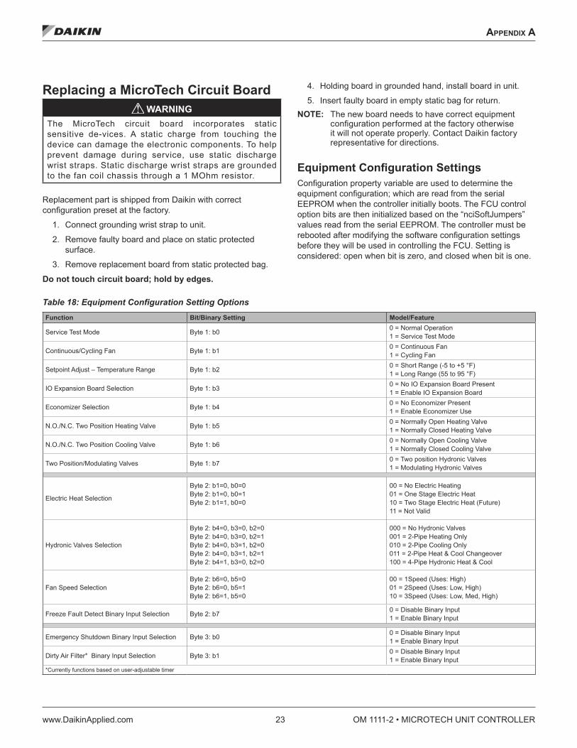
Replacing a MicroTech Circuit Board
Replacement part is shipped from Daikin with correct configuration preset at the factory.
1 . Connect grounding wrist strap to unit .
2 . Remove faulty board and place on static protected surface .
3 . Remove replacement board from static protected bag .
Do not touch circuit board; hold by edges .
4 . Holding board in grounded hand, install board in unit .
5 . Insert faulty board in empty static bag for return .NOTE: The new board needs to have correct equipment
configuration performed at the factory otherwise it will not operate properly . Contact Daikin factory representative for directions .
Equipment Configuration Settings Configuration property variable are used to determine the equipment configuration; which are read from the serial EEPROM when the controller initially boots . The FCU control option bits are then initialized based on the “nciSoftJumpers” values read from the serial EEPROM . The controller must be rebooted after modifying the software configuration settings before they will be used in controlling the FCU . Setting is considered: open when bit is zero, and closed when bit is one .
Table 18: Equipment Configuration Setting OptionsFunction Bit/Binary Setting Model/Feature
Service Test Mode Byte 1: b0 0 = Normal Operation 1 = Service Test Mode
Continuous/Cycling Fan Byte 1: b1 0 = Continuous Fan 1 = Cycling Fan
Setpoint Adjust – Temperature Range Byte 1: b2 0 = Short Range (-5 to +5 °F) 1 = Long Range (55 to 95 °F)
IO Expansion Board Selection Byte 1: b3 0 = No IO Expansion Board Present 1 = Enable IO Expansion Board
Economizer Selection Byte 1: b4 0 = No Economizer Present 1 = Enable Economizer Use
N .O ./N .C . Two Position Heating Valve Byte 1: b5 0 = Normally Open Heating Valve 1 = Normally Closed Heating Valve
N .O ./N .C . Two Position Cooling Valve Byte 1: b6 0 = Normally Open Cooling Valve 1 = Normally Closed Cooling Valve
Two Position/Modulating Valves Byte 1: b7 0 = Two position Hydronic Valves 1 = Modulating Hydronic Valves
Electric Heat Selection
Byte 2: b1=0, b0=0 Byte 2: b1=0, b0=1 Byte 2: b1=1, b0=0
00 = No Electric Heating 01 = One Stage Electric Heat 10 = Two Stage Electric Heat (Future) 11 = Not Valid
Hydronic Valves Selection
Byte 2: b4=0, b3=0, b2=0 Byte 2: b4=0, b3=0, b2=1 Byte 2: b4=0, b3=1, b2=0 Byte 2: b4=0, b3=1, b2=1 Byte 2: b4=1, b3=0, b2=0
000 = No Hydronic Valves 001 = 2-Pipe Heating Only 010 = 2-Pipe Cooling Only 011 = 2-Pipe Heat & Cool Changeover 100 = 4-Pipe Hydronic Heat & Cool
Fan Speed SelectionByte 2: b6=0, b5=0 Byte 2: b6=0, b5=1 Byte 2: b6=1, b5=0
00 = 1Speed (Uses: High) 01 = 2Speed (Uses: Low, High) 10 = 3Speed (Uses: Low, Med, High)
Freeze Fault Detect Binary Input Selection Byte 2: b7 0 = Disable Binary Input 1 = Enable Binary Input
Emergency Shutdown Binary Input Selection Byte 3: b0 0 = Disable Binary Input 1 = Enable Binary Input
Dirty Air Filter* Binary Input Selection Byte 3: b1 0 = Disable Binary Input 1 = Enable Binary Input
*Currently functions based on user-adjustable timer
WARNINGThe MicroTech circuit board incorporates static sensitive de-vices . A static charge from touching the device can damage the electronic components . To help prevent damage during service, use static discharge wrist straps . Static discharge wrist straps are grounded to the fan coil chassis through a 1 MOhm resistor .
appendIx a
www .DaikinApplied .com 23 OM 1111-2 • MICROTECH UNIT CONTROLLER
appendIx B
MicroTech Unit Controller with an optional lonWorks® Communication Module For installation and operation information on LonWorks Communication Module and other ancillary control components, see:
• IM 1012 — MicroTech III Fan Coil LonWorks Communication Module .
• IM 933 — LonMaker Integration Plug-in Tool: For use with the MicroTech III Unit Controller .
• IM 1171 — Digitally Adjustable Display Sensor Installation and Maintenance Manual
Each Daikin ThinLine fan coil can be equipped with a LonWorks communication module that is LonMark 3.4 certified to meet the LonMark Space Comfort Control (SCC) profile for fan coils . The controller is microprocessor-based and is designed to communicate over a LonWorks network with the optional factory or field-installed communication module.
The unit controller is programmed and tested with all the logic required to monitor and control the unit . An optional wall sensor may be used with the communication module to provide limited local control of the Fan Coil or Cabinet Unit Heater unit . The unit controller monitors water and air temperatures and passes information to the communication module . The module communicates with the BAS to provide network control of the Fan Coil or Cabinet Unit Heater unit .
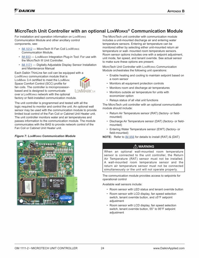
Figure 7: LonWorks Communication Module
The MicroTech unit controller with communication module includes a unit-mounted discharge air and entering water temperature sensors . Entering air temperature can be monitored either by selecting either unit-mounted return air temperature or wall- mounted room temperature sensors . Room sensor options includes one with a setpoint adjustment, unit mode, fan speed, and tenant override . See actual sensor to make sure these options are present .
MicroTech Unit Controller with LonWorks Communication Module orchestrates the following unit operations:
• Enable heating and cooling to maintain setpoint based on a room sensor
• Monitors all equipment protection controls• Monitors room and discharge air temperatures• Monitors outside air temperature for units with
economizer option• Relays status of all vital unit functions
The MicroTech unit controller with an optional communication module should include:
• Return Air Temperature sensor (RAT) (factory- or field-mounted)
• Discharge Air Temperature sensor (DAT) (factory- or field-mounted)
• Entering Water Temperature sensor (EWT) (factory- or field-mounted)
NOTE: Refer to IM 956 for details to install (RAT) & (DAT)
The communication module provides access to setpoints for operational control
Available wall sensors include:
• Room sensor with LED status and tenant override button• Room sensor with LCD display, fan speed selection
switch, tenant override button, and ±5°F setpoint adjustment
• Room sensor with LCD display, fan speed selection switch, tenant override button, 55° to 95°F setpoint adjustment
WARNINGWhen an optional wall-mounted room temperature sensor is connected to the unit controller, the Return Air Temperature (RAT) sensor must not be installed . A wall-mounted room temperature sensor and the return air temperature sensor must not be connected simultaneously or the unit will not operate properly .
OM 1111-2 • MICROTECH UNIT CONTROLLER 24 www .DaikinApplied .com
appendIx B
appendIx c
MicroTech Unit Controller with an optional BACnet® Communication Module For installation and operation information on MicroTech unit controller and other ancillary components, see:
• IM 1013 — MicroTech Fan Coil BACnet Communication Module
• IM 1171 — Digitally Adjustable Display Sensor Installation and Maintenance Manual
Daikin ThinLine fan coils and cabinet unit heaters are available with an optional BACnet MS/TP communication module that is designed to communicate over a BACnet MS/TP communications network to a building automation system (BAS). It can be factory or field-installed.
The module makes operational data and commands available on a communications network using BACnet objects and properties:
• The network cable is a shielded twisted-pair cable• Network communications run up to 76 .8 Kbps• DIP switches on the controller enable the MS/TP MAC
address to be set in the range 0-127• Four green status LEDs on the communication
module indicate communication activity on the MS/TP communication network and with the unit controller
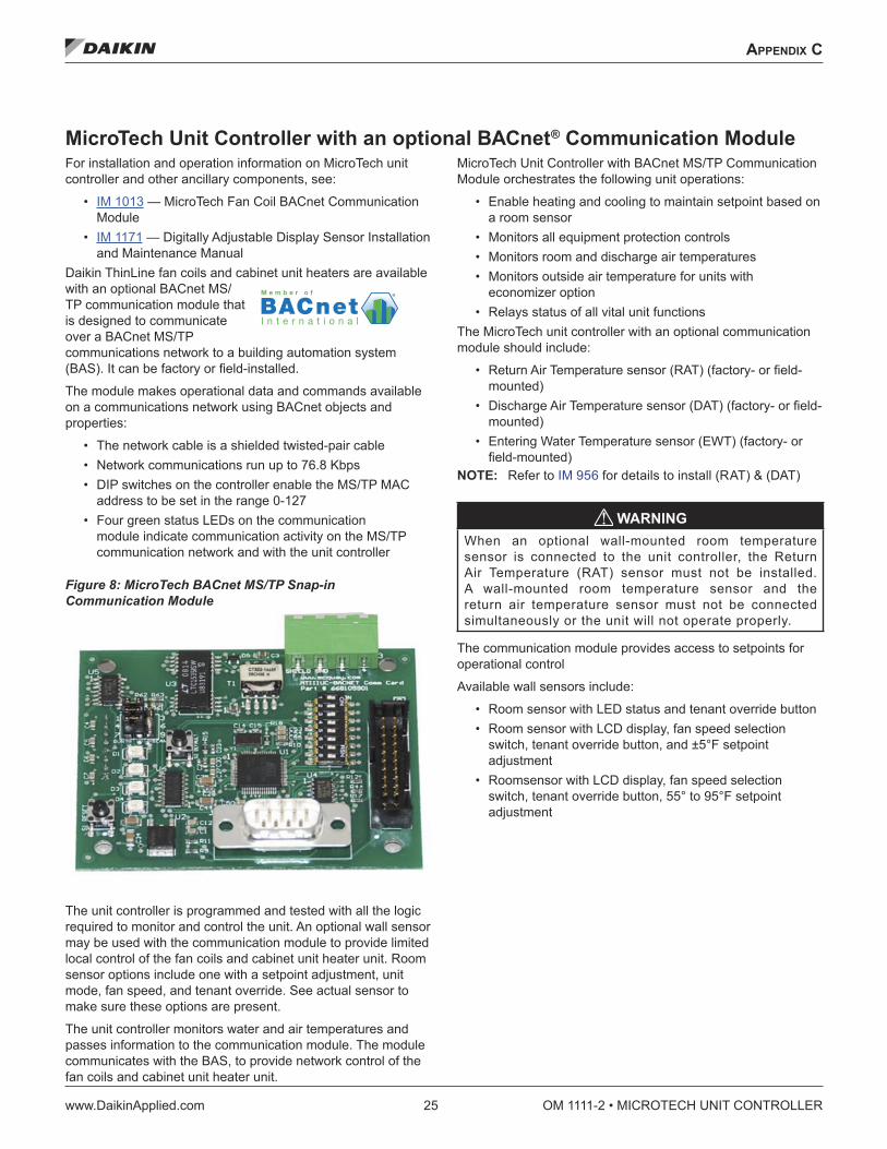
Figure 8: MicroTech BACnet MS/TP Snap-in Communication Module
The unit controller is programmed and tested with all the logic required to monitor and control the unit . An optional wall sensor may be used with the communication module to provide limited local control of the fan coils and cabinet unit heater unit . Room sensor options include one with a setpoint adjustment, unit mode, fan speed, and tenant override . See actual sensor to make sure these options are present .
The unit controller monitors water and air temperatures and passes information to the communication module . The module communicates with the BAS, to provide network control of the fan coils and cabinet unit heater unit .
MicroTech Unit Controller with BACnet MS/TP Communication Module orchestrates the following unit operations:
• Enable heating and cooling to maintain setpoint based on a room sensor
• Monitors all equipment protection controls• Monitors room and discharge air temperatures• Monitors outside air temperature for units with
economizer option• Relays status of all vital unit functions
The MicroTech unit controller with an optional communication module should include:
• Return Air Temperature sensor (RAT) (factory- or field-mounted)
• Discharge Air Temperature sensor (DAT) (factory- or field-mounted)
• Entering Water Temperature sensor (EWT) (factory- or field-mounted)
NOTE: Refer to IM 956 for details to install (RAT) & (DAT)
The communication module provides access to setpoints for operational control
Available wall sensors include:
• Room sensor with LED status and tenant override button• Room sensor with LCD display, fan speed selection
switch, tenant override button, and ±5°F setpoint adjustment
• Roomsensor with LCD display, fan speed selection switch, tenant override button, 55° to 95°F setpoint adjustment
WARNINGWhen an optional wall-mounted room temperature sensor is connected to the unit controller, the Return Air Temperature (RAT) sensor must not be installed . A wall-mounted room temperature sensor and the return air temperature sensor must not be connected simultaneously or the unit will not operate properly .
appendIx c
www .DaikinApplied .com 25 OM 1111-2 • MICROTECH UNIT CONTROLLER
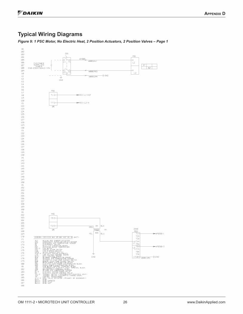
appendIx d
Typical Wiring DiagramsFigure 9: 1 PSC Motor, No Electric Heat, 2 Position Actuators, 2 Position Valves – Page 1
OM 1111-2 • MICROTECH UNIT CONTROLLER 26 www .DaikinApplied .com
appendIx d
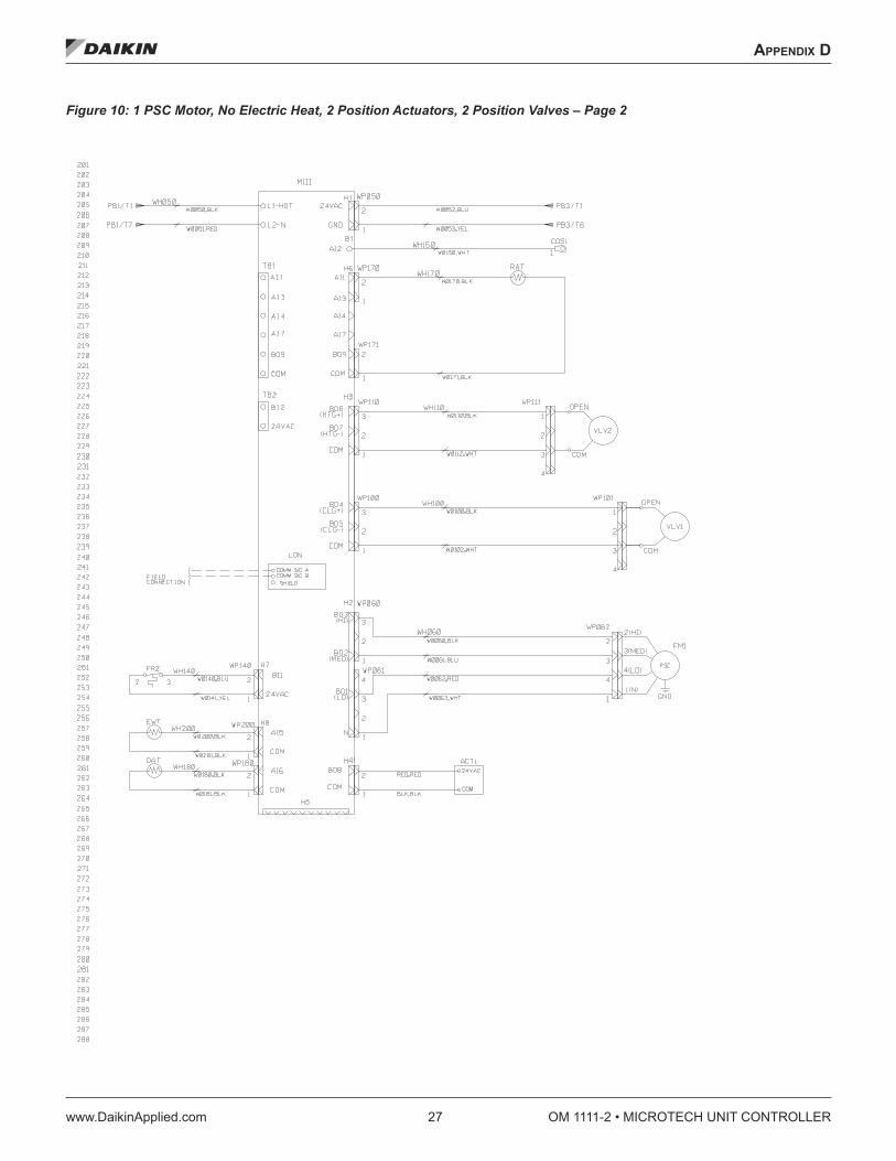
Figure 10: 1 PSC Motor, No Electric Heat, 2 Position Actuators, 2 Position Valves – Page 2
appendIx d
www .DaikinApplied .com 27 OM 1111-2 • MICROTECH UNIT CONTROLLER
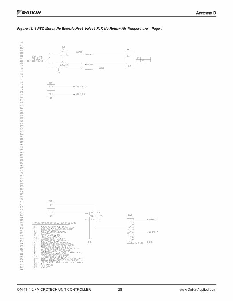
Figure 11: 1 PSC Motor, No Electric Heat, Valve1 FLT, No Return Air Temperature – Page 1
OM 1111-2 • MICROTECH UNIT CONTROLLER 28 www .DaikinApplied .com
appendIx d
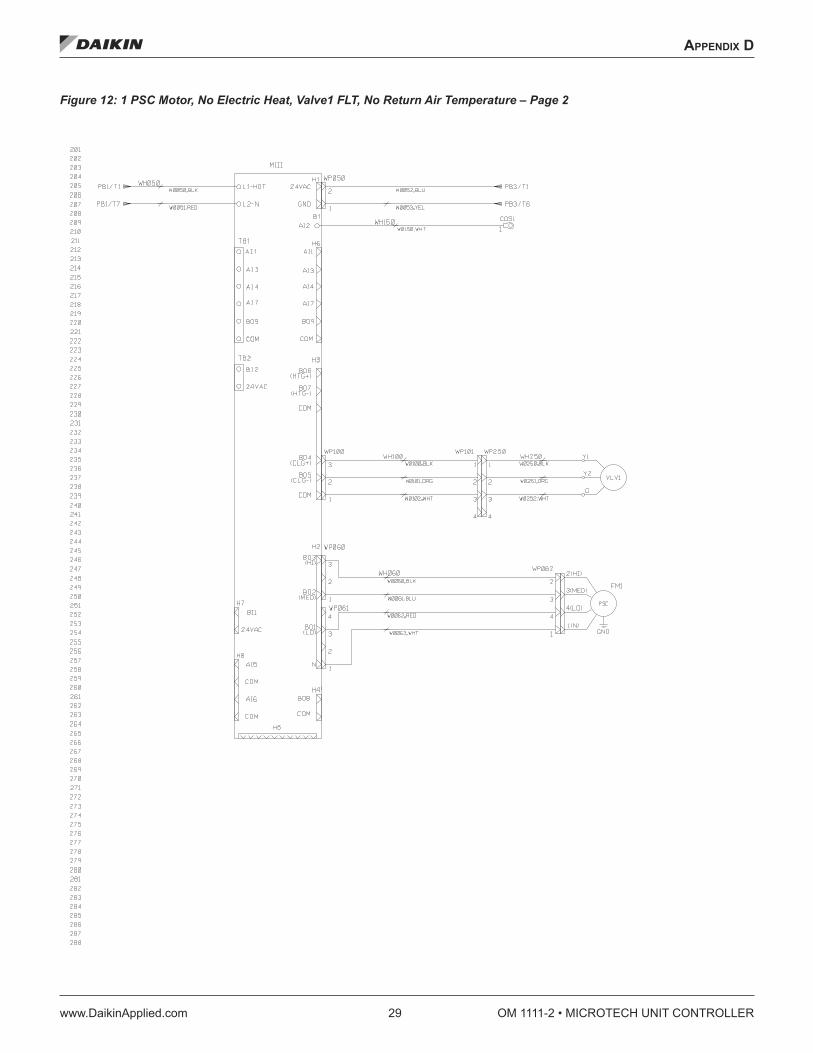
Figure 12: 1 PSC Motor, No Electric Heat, Valve1 FLT, No Return Air Temperature – Page 2
appendIx d
www .DaikinApplied .com 29 OM 1111-2 • MICROTECH UNIT CONTROLLER
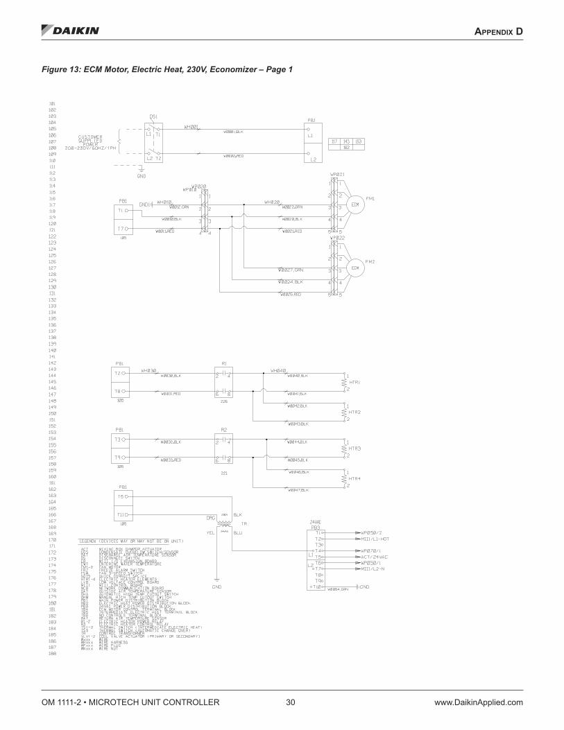
Figure 13: ECM Motor, Electric Heat, 230V, Economizer – Page 1
OM 1111-2 • MICROTECH UNIT CONTROLLER 30 www .DaikinApplied .com
appendIx d
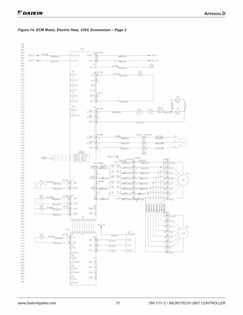
Figure 14: ECM Motor, Electric Heat, 230V, Economizer – Page 2
appendIx d
www .DaikinApplied .com 31 OM 1111-2 • MICROTECH UNIT CONTROLLER
OM 1111-2 (10/15) ©2015 Daikin Applied | (800) 432–1342 | www .DaikinApplied .com
Daikin Applied Training and Development
Now that you have made an investment in modern, efficient Daikin equipment, its care should be a high priority. For training information on all Daikin HVAC products, please visit us at www.DaikinApplied.com and click on Training, or call 540-248-9646 and ask for the Training Department.
Warranty
All Daikin equipment is sold pursuant to its standard terms and conditions of sale, including Limited Product Warranty. Consult your local Daikin Applied representative for warranty details. To find your local Daikin Applied representative, go to www.DaikinApplied.com.
Aftermarket Services
To find your local parts office, visit www.DaikinApplied.com or call 800-37PARTS (800-377-2787). To find your local service office, visit www.DaikinApplied.com or call 800-432-1342.
This document contains the most current product information as of this printing. For the most up-to-date product information, please go to www.DaikinApplied.com.
Products manufactured in an ISO Certified Facility.