Embed Size (px)
Citation preview
ericssonz
INSTRUCTION MANUAL
CONVENTIONAL SIMULCASTSYSTEM OVERVIEW
Ericsson Inc.Private Radio SystemsMountain View RoadLynchburg, Virginia 24502 AE/LZB 119 1913/1 R1A1-800-528-7711 (Outside USA, 804-528-7711) Printed in U.S.A.
TABLE OF CONTENTS
Page
CONVENTIONAL SIMULCAST SYSTEM OVERVIEW . . . . . . . . . . . . . . . . . . . . . . . . . . 1
CAPTURE/NON-CAPTURE ZONES . . . . . . . . . . . . . . . . . . . . . . . . . . . . . . . . . . 1
LONG TERM SYSTEM STABILITY . . . . . . . . . . . . . . . . . . . . . . . . . . . . . . . . . . 1
SYSTEM EQUALIZATION . . . . . . . . . . . . . . . . . . . . . . . . . . . . . . . . . . . . . . . 1
SYSTEM INTERFACE REQUIREMENTS . . . . . . . . . . . . . . . . . . . . . . . . . . . . . . . 2Simulcast Support Equipment . . . . . . . . . . . . . . . . . . . . . . . . . . . . . . . . . . 2
STANDARD SYSTEM CONFIGURATIONS . . . . . . . . . . . . . . . . . . . . . . . . . . . . . . 2
SYSTEM DESCRIPTION . . . . . . . . . . . . . . . . . . . . . . . . . . . . . . . . . . . . . . . . . . . 2
CONTROL POINT . . . . . . . . . . . . . . . . . . . . . . . . . . . . . . . . . . . . . . . . . . . . 2Analog Voting Equipment . . . . . . . . . . . . . . . . . . . . . . . . . . . . . . . . . . . . 2Remote Keying Panel . . . . . . . . . . . . . . . . . . . . . . . . . . . . . . . . . . . . . . 2Analog Processing Equipment . . . . . . . . . . . . . . . . . . . . . . . . . . . . . . . . . . 2Compressor . . . . . . . . . . . . . . . . . . . . . . . . . . . . . . . . . . . . . . . . . . . 2Audio Bridge . . . . . . . . . . . . . . . . . . . . . . . . . . . . . . . . . . . . . . . . . . . 2Audio Equalizer . . . . . . . . . . . . . . . . . . . . . . . . . . . . . . . . . . . . . . . . . 2Analog (Audio) Delay . . . . . . . . . . . . . . . . . . . . . . . . . . . . . . . . . . . . . . 2Channel Guard Modulator . . . . . . . . . . . . . . . . . . . . . . . . . . . . . . . . . . . . 3Test Equipment . . . . . . . . . . . . . . . . . . . . . . . . . . . . . . . . . . . . . . . . . . 3Tone Decoder Shelf . . . . . . . . . . . . . . . . . . . . . . . . . . . . . . . . . . . . . . . 3
TRANSMIT SITE . . . . . . . . . . . . . . . . . . . . . . . . . . . . . . . . . . . . . . . . . . . . . 3MASTR III Repeater Cabinet . . . . . . . . . . . . . . . . . . . . . . . . . . . . . . . . . . 3High Stability Oscillator . . . . . . . . . . . . . . . . . . . . . . . . . . . . . . . . . . . . 3RF Equipment . . . . . . . . . . . . . . . . . . . . . . . . . . . . . . . . . . . . . . . . . . 3
SIMULCAST MAINTENANCE MANUALS . . . . . . . . . . . . . . . . . . . . . . . . . . . . . . . . . 3
SIGNAL INTERCONNECT DIAGRAMS . . . . . . . . . . . . . . . . . . . . . . . . . . . . . . . . . . . 3
SIGNAL FLOW DIAGRAMS . . . . . . . . . . . . . . . . . . . . . . . . . . . . . . . . . . . . . . 3Control Point . . . . . . . . . . . . . . . . . . . . . . . . . . . . . . . . . . . . . . . . . . . 3Transmit Site . . . . . . . . . . . . . . . . . . . . . . . . . . . . . . . . . . . . . . . . . . . 3
INDEX OF SIMULCAST MAINTENANCE MANUALS . . . . . . . . . . . . . . . . . . . . . . . . . . 4
DIAGRAMS . . . . . . . . . . . . . . . . . . . . . . . . . . . . . . . . . . . . . . . . . . . . . . . . . . . 5
CONVENTIONAL SIMULCASTSYSTEM OVERVIEW
The Conventional Simulcast System enhances communi-cations in areas where the size of the coverage area is toolarge and/or the communications paths are blocked or hin-dered by irregular terrain or other obstacles to be reliablyserviced by a single site system. When these conditions existand the talk out coverage is inadequate, the need for a simul-cast system is indicated. It is also advantageous in areaswhere available frequencies are limited since it utilizes thesame set of frequencies at each site. All transmissions aresystem wide; i.e., messages are transmitted simultaneouslyfrom all sites on the same RF frequency.
A typical simulcast system includes a Control Point andtwo or more Transmit Sites. The Transmit Sites are locatedso that two way communications are possible anywhere in aspecified area. The Control Point exercises control over allTransmit Sites. All outbound call transmissions are initiatedfrom the Control Point and all inbound calls from mobiles orportables are received at one or more of the Transmit Sitesand routed to the Control Point for processing. These sig-nals from all the Transmit sites are compared and the signalwith the best audio quality is voted as the one to be equal-ized and delayed before being sent to all sites to be repeatedoutbound to the mobiles and portables.
CAPTURE/NON-CAPTURE ZONES
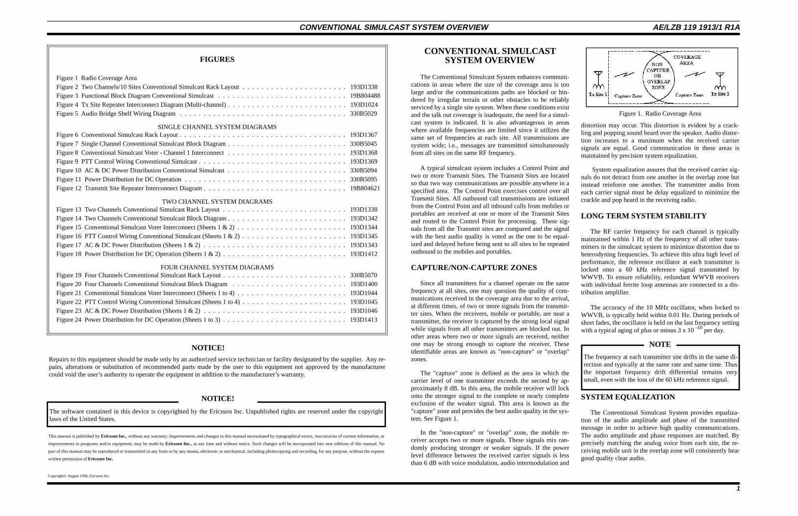
Since all transmitters for a channel operate on the samefrequency at all sites, one may question the quality of com-munications received in the coverage area due to the arrival,at different times, of two or more signals from the transmit-ter sites. When the receivers, mobile or portable, are near atransmitter, the receiver is captured by the strong local signalwhile signals from all other transmitters are blocked out. Inother areas where two or more signals are received, neitherone may be strong enough to capture the receiver. Theseidentifiable areas are known as "non-capture" or "overlap"zones.
The "capture" zone is defined as the area in which thecarrier level of one transmitter exceeds the second by ap-proximately 8 dB. In this area, the mobile receiver will lockonto the stronger signal to the complete or nearly completeexclusion of the weaker signal. This area is known as the"capture" zone and provides the best audio quality in the sys-tem. See Figure 1.
In the "non-capture" or "overlap" zone, the mobile re-ceiver accepts two or more signals. These signals mix ran-domly producing stronger or weaker signals. If the powerlevel difference between the received carrier signals is lessthan 6 dB with voice modulation, audio intermodulation and
distortion may occur. This distortion is evident by a crack-ling and popping sound heard over the speaker. Audio distor-tion increases to a maximum when the received carriersignals are equal. Good communication in these areas ismaintained by precision system equalization.
System equalization assures that the received carrier sig-nals do not detract from one another in the overlap zone butinstead reinforce one another. The transmitter audio fromeach carrier signal must be delay equalized to minimize thecrackle and pop heard in the receiving radio.
LONG TERM SYSTEM STABILITY
The RF carrier frequency for each channel is typicallymaintained within 1 Hz of the frequency of all other trans-mitters in the simulcast system to minimize distortion due toheterodyning frequencies. To achieve this ultra high level ofperformance, the reference oscillator at each transmitter islocked onto a 60 kHz reference signal transmitted byWWVB. To ensure reliability, redundant WWVB receiverswith individual ferrite loop antennas are connected to a dis-tribution amplifier.
The accuracy of the 10 MHz oscillator, when locked toWWVB, is typically held within 0.01 Hz. During periods ofshort fades, the oscillator is held on the last frequency settingwith a typical aging of plus or minus 3 x 10 -10 per day.
SYSTEM EQUALIZATION
The Conventional Simulcast System provides equaliza-tion of the audio amplitude and phase of the transmittedmessage in order to achieve high quality communications.The audio amplitude and phase responses are matched. Byprecisely matching the analog voice from each site, the re-ceiving mobile unit in the overlap zone will consistently heargood quality clear audio.
Copyright© August 1996, Ericsson Inc.
Repairs to this equipment should be made only by an authorized service technician or facility designated by the supplier. Any re-pairs, alterations or substitution of recommended parts made by the user to this equipment not approved by the manufacturercould void the user’s authority to operate the equipment in addition to the manufacturer’s warranty.
NOTICE!
This manual is published by Ericsson Inc., without any warranty. Improvements and changes to this manual necessitated by typographical errors, inaccuracies of current information, or
improvements to programs and/or equipment, may be made by Ericsson Inc., at any time and without notice. Such changes will be incorporated into new editions of this manual. No
part of this manual may be reproduced or transmitted in any form or by any means, electronic or mechanical, including photocopying and recording, for any purpose, without the express
written permission of Ericsson Inc.
The software contained in this device is copyrighted by the Ericsson Inc. Unpublished rights are reserved under the copyrightlaws of the United States.
NOTICE!
FIGURES
Figure 1 Radio Coverage AreaFigure 2 Two Channels/10 Sites Conventional Simulcast Rack Layout . . . . . . . . . . . . . . . . . . . . . . 193D1338Figure 3 Functional Block Diagram Conventional Simulcast . . . . . . . . . . . . . . . . . . . . . . . . . . . 19B804488Figure 4 Tx Site Repeater Interconnect Diagram (Multi-channel) . . . . . . . . . . . . . . . . . . . . . . . . . 193D1024Figure 5 Audio Bridge Shelf Wiring Diagram . . . . . . . . . . . . . . . . . . . . . . . . . . . . . . . . . . . 330B5029
SINGLE CHANNEL SYSTEM DIAGRAMSFigure 6 Conventional Simulcast Rack Layout . . . . . . . . . . . . . . . . . . . . . . . . . . . . . . . . . . . 193D1367Figure 7 Single Channel Conventional Simulcast Block Diagram . . . . . . . . . . . . . . . . . . . . . . . . . 330B5045Figure 8 Conventional Simulcast Voter - Channel 1 Interconnect . . . . . . . . . . . . . . . . . . . . . . . . . 193D1368Figure 9 PTT Control Wiring Conventional Simulcast . . . . . . . . . . . . . . . . . . . . . . . . . . . . . . . 193D1369Figure 10 AC & DC Power Distribution Conventional Simulcast . . . . . . . . . . . . . . . . . . . . . . . . . 330B5094Figure 11 Power Distribution for DC Operation . . . . . . . . . . . . . . . . . . . . . . . . . . . . . . . . . . 330B5095Figure 12 Transmit Site Repeater Interconnect Diagram . . . . . . . . . . . . . . . . . . . . . . . . . . . . . . 19B804621
TWO CHANNEL SYSTEM DIAGRAMSFigure 13 Two Channels Conventional Simulcast Rack Layout . . . . . . . . . . . . . . . . . . . . . . . . . . 193D1338Figure 14 Two Channels Conventional Simulcast Block Diagram . . . . . . . . . . . . . . . . . . . . . . . . . 193D1342Figure 15 Conventional Simulcast Voter Interconnect (Sheets 1 & 2) . . . . . . . . . . . . . . . . . . . . . . . 193D1344Figure 16 PTT Control Wiring Conventional Simulcast (Sheets 1 & 2) . . . . . . . . . . . . . . . . . . . . . . 193D1345Figure 17 AC & DC Power Distribution (Sheets 1 & 2) . . . . . . . . . . . . . . . . . . . . . . . . . . . . . . 193D1343Figure 18 Power Distribution for DC Operation (Sheets 1 & 2) . . . . . . . . . . . . . . . . . . . . . . . . . . 193D1412
FOUR CHANNEL SYSTEM DIAGRAMSFigure 19 Four Channels Conventional Simulcast Rack Layout . . . . . . . . . . . . . . . . . . . . . . . . . . 330B5070Figure 20 Four Channels Conventional Simulcast Block Diagram . . . . . . . . . . . . . . . . . . . . . . . . 193D1400Figure 21 Conventional Simulcast Voter Interconnect (Sheets 1 to 4) . . . . . . . . . . . . . . . . . . . . . . . 193D1044Figure 22 PTT Control Wiring Conventional Simulcast (Sheets 1 to 4) . . . . . . . . . . . . . . . . . . . . . . 193D1045Figure 23 AC & DC Power Distribution (Sheets 1 & 2) . . . . . . . . . . . . . . . . . . . . . . . . . . . . . . 193D1046Figure 24 Power Distribution for DC Operation (Sheets 1 to 3) . . . . . . . . . . . . . . . . . . . . . . . . . . 193D1413
Figure 1. Radio Coverage Area
NOTICE!
The frequency at each transmitter site drifts in the same di-rection and typically at the same rate and same time. Thusthe important frequency drift differential remains verysmall, even with the loss of the 60 kHz reference signal.
NOTE
CONVENTIONAL SIMULCAST SYSTEM OVERVIEW AE/LZB 119 1913/1 R1A
1
SYSTEM INTERFACE REQUIREMENTS
In addition to the simulcast and related peripheral equip-ment provided, audio lines must be installed to complete thevoice paths to/from the multiplex equipment, the voter/si-mulcast equipment, and the console. The number of 4-wireE & M voice channels required between the Transmit Siteand the Control Point is equal to the total number of chan-nels plus an additional one per site when Channel Guard isrequired. To assure a high quality simulcast system the audiolines must meet the Bell System Specification for 3002grade levels and be routed over a phase stable network.
A digital multiplex/microwave system is strongly recom-mended. If an analog multiplex system is employed, it mustincorporate a "phase stable"/simulcast phase locked system.
Telephone lines are generally not acceptable for routingsignals between the Transmitter Site and the Control Point.
Simulcast Support Equipment
• Multiplex/microwave - Digital or AnalogMultiplex System. Digital is preferred. Channelrequirements as indicated above.
• Antenna System for WWVB receivers, if used.RG-58 feed may be used.
STANDARD SYSTEM CONFIGURATIONS
The Conventional Simulcast System is available in threestandard configurations that can be tailored to meet specificcustomer requirements. All systems are built to one of thefollowing configurations with sites and/or channels omittedwhen design requirements fall between configuration inter-vals. The current Control Point standard configurations are:
1 Channel - up to 10 Sites - Requires 1 Cabinet/Rack plus Test Equipment
2 Channel - up to 10 Sites - Requires 2 Cabinet/Rack plus Test Equipment
4 Channel - up to 10 Sites - Requires 3 Cabinet/Rack plus Test Equipment
Figure 2 shows a typical rack-up of the Control Pointequipment for a 2 Channel System with up to 10 Sites.Equipment rack ups, block diagrams and interconnect dia-grams are shown at the end of this manual.
All of the voting equipment, analog processing equip-ment, analog delay equipment and console interface circuitsare located at the Control Point. The dispatch console maybe located at another site or it may be co-located at the Con-trol Point. Figure 2 does not show any Console equipmentother than the Interface board. When Channel Guard (CG)
is required, the master and standby oscillators are located atthe Control Point as shown in the Figure.
Transmit Site equipment configurations are based on thenumber of RF channels. The Transmit Site configuration isthe same as for multiracking of MASTR III conventionalstations except for the addition of the WWVB reference os-cillator (one per site), an EDACS Interface Panel and audiobridge shelf for distribution of CG (one of each for eachcabinet/rack), and a CG Demodulator circuit card for eachMASTR III. The demodulator card is a plug in card that isinstalled on the MASTR III control shelf. The Tx Combinerand Rx Multicoupler are housed in a separate cabinet orrack.
Transmit site equipment is housed in either 69” or 83”cabinets. The Control Point equipment is housed in either83” deep cabinets or 86-inch deep open relay racks (19-inch). Each rack is configured to meet customer system re-quirements with capability for cabinet to cabinet electricalinterconnection by overhead cabling.
SYSTEM DESCRIPTION
A typical simulcast system includes equipment that is di-vided into two main functional areas: Control Point andTransmit Site. The Control Point is linked to each of the re-mote Transmit Sites by microwave or fiber optic cablethrough multiplex equipment located at the Control Pointand the Transmit Sites. A typical functional diagram of a twosite simulcast system is shown in Figure 3 (Multiplex andthe transmission equipment not shown). Figure 3 showstypical routing of signals for a single conventional simulcastchannel with two remote sites and a Dispatch Console.
Receive signals from the remote sites are routed to theAnalog Voting equipment which selects a signal that isbased on the best audio quality. The selected signal or votedaudio is processed (amplitude equalized & delayed) beforebeing routed to all the remote Transmitters.
Voted audio and CG for each Transmit Site is individu-ally time delayed by audio delay circuits at the Control Pointto compensate for the differences in distance from the Con-trol Point to the specific Transmit Site. The delayed signalsare fed to the multiplexer for transmission to all simulcasttransmitters.
CONTROL POINT
The functions provided by equipment located at the Con-trol Point include system interface, audio processing, Chan-nel Guard processing, transmit keying for the remote sites,system alignment and system test . The Control Point equip-
ment interfaces with the dispatch console by accepting thestandard control sequence (2175 Hz + function tone) via a 4wire connection. When the 2175 Hz tone is received by the si-mulcast equipment from the console, the voted audio isblocked and console audio is transmitted on the selected chan-nel.
Analog Voting Equipment
Receive Audio signals from each of the MASTR III repeat-ers are compared in the voting selector where the signal withthe best audio quality is selected as the “voted” signal. Thevoting selector provides continuous voting to ensure that thebest available signal is being provided to the system for the re-peat operation. Voted audio is routed from the voter to theAudio Signal Processing equipment.
Remote Keying Panel
The Remote Keying Panel (RKP) which is part of the vot-ing equipment generates a Transmit PTT signal when the votedsignal is first detected and remains until the signal ceases. ThePTT signal is routed to the Transmit Site via the E & M Keyingof the multiplex channel card. Additionally, a Transmit PTTsignal is generated by the RKP when an input is received froma dispatch console. When a 2175 Hz transmit tone is detectedby the Console Interface Board, the RKP generates a TransmitPTT signal as long as the 2175 Hz hold tone is present.
When both voted audio and console audio are present at thesame time, only the console audio is passed on to the remotesites and voted audio is inhibited. When the console transmis-sion ends, the voted audio transmission resumes. This is theconsole override function that allows a dispatch console opera-tor to have priority over one of the field units.
Analog Processing Equipment
Voice channel inputs are received from the Transmit Sitesvia the analog voter or from the Dispatch Console and passedto the compressor located in the analog processing shelf.
The signal (either voted audio or console audio) is firstprocessed by the compressor and amplitude/phase equalizer.The Compressor, Audio Bridge and Equalizer boards are lo-cated in the Processing Shelf. The absolute delay is then pro-vided by a digitally controlled analog delay unit which isaccomplished by circuit cards in the Delay Shelf. The relativephase between audio signals transmitted from different trans-mitter sites (on the same channel) is maintained within 25 de-grees between 600 and 2600 Hz. The typical targetedadjustment values will be the same as the resolution of thephase measuring instruments; i.e., approximately 10 degrees inthe same audio range. The relative audio amplitude responsewill be within 0.25 dB from 400 to 3000 Hz.
Compressor (Audio Processing Shelf)
The compressor combines continuously adjustable lineargain with linear level limiting to provide a low distortion com-pressed voice frequency signal. The gain is adjustable withinthe range of 0 to 20 dB, with a maximum output level of +17dBm.
A front panel adjustment allows the output signal to be setto any level between -30 and +17 dBm, with up to 30 dB gain.Compression is linear, resulting in less than 2% total distortionat 30 dB compression.
Audio Bridge (Audio Processing Shelf)
The audio bridge serves as a signal splitter to provide aseparate buffered audio source for each site on a given channel.Its gain has been chosen so that the per site equalizer whichfollows operates well within the level adjustment range. A sin-gle audio bridge provides audio bridging of up to 10 singleended outputs. The output of the audio bridge is passed to theaudio equalizer.
Audio Equalizer (Audio Processing Shelf)
The audio equalizer, also located in the analog processingshelf, provides precisely controlled amplitude and phaseequalization for one voice circuit. The amplitude equalizationcircuitry is switch-optioned for flat response.
Phase equalization is provided by 13 individual delay sec-tions, providing up to 1500 microseconds of continuously ad-justable delay at equally spaced frequencies across the voiceband. Delay may be adjusted at 200 Hz intervals from 600 to3000 Hz. To eliminate frequency response fluctuations, up to 6dB of inband amplitude ripple equalization is available at eachof the 13 delay sections.
The equalizer also provides flat adjustable insertion gainfrom -15 to +15 dB to coordinate the module output level witha variety of input levels. The maximum output level of themodule is +5 dBm. The terminating impedance at the moduleinput and output ports is 600 ohms balanced. The equalizedvoice/analog output is then passed to the audio delay board.
Analog Delay (Delay Shelf)
The analog delay board delays all analog signals receivedfor transmission to the Transmit Site by an amount correspond-ing to its distance from the Control Point. Each analog delayboard delays the audio signals for one specific transmitter. Thisensures simultaneous arrival of the audio signals in the simul-cast "overlap" region.
AE/LZB 119 1913/1 R1A CONVENTIONAL SIMULCAST SYSTEM OVERVIEW
2
The amount of audio delay provided to the analog signals isdetermined by the setting of two pairs of dip switches on theaudio board; one pair (S1 & S2) sets the delay for the primaryaudio path and the other pair (S3 & S4) sets the delay for thesecondary path. The primary path is normally used while thesecondary path is used in loop microwave system configura-tions. The delay is provided in increments of 1 microsecondwith a maximum delay of 32 milliseconds. Delay is providedfor up to 13 audio inputs. Analog delay boards are used only atthe Control Point.
Channel Guard Modulator
When the system requires CTCSS, an optional ChannelGuard (CG) modulator is included as part of the control pointequipment. In order to adjust for different signal paths throughout the Conventional Simulcast System a single CG oscillatorgenerates the CG tone for the entire system which is then dis-tributed to each remote site. The CG tone is distributedthrough out the system as modulation on an 1800 Hz carrier.At each remote site the CG modulation is stripped from the1800 Hz carrier and applied to the MASTR III repeater. At thecontrol point the CG signal is routed through the same absolutedelay as the voted audio signals.
The Channel Guard Modulator consists of a Master ToneBoard, a Hot Standby Tone Board and a Control Board that de-tects any failure in the Master Board and switches to theStandby Board. The three boards are mounted in a 2 rack unitshelf.
The test equipment rack provides the means to test, trou-bleshoot and align a simulcast system. It contains the controlpanels, digital storage scope, signal analyzer, equalizer testpanel, alignment/test radio, balun panel, variable delay panels,transmission test set, and power supply.
Test Equipment
The test equipment rack provides the means to test, trou-bleshoot and align a simulcast system. It contains the controlpanels, digital storage scope, signal analyzer, equalizer testpanel, alignment/test radio, balun panel, variable delay panels,transmission test set, and power supply. System alignment andtest functions may be completed from the control point usingequipment in the Test Equipment rack and the PTT ControlPanel. A control panel, consisting of (75) 3-position switches,controls the PTT function for ten sites for each channel. Theseswitches allow individual transmitters to be operated in orderto adjust delay and gain for each path. Other test equipment isused to view the operation of each channel at each site and ad-just the amplitude and delay for best system operation. Jack-field access is also provided to the transmit and receive audiocircuits for alignment, test and routine troubleshooting.
Tone Decoder Shelf
A RPTR ON/OFF function allows the dispatch console op-erator to inhibit repeating of the voted audio so that the onlyopen communication path is to/from the dispatch console. TheRPTR ON/OFF function is provided by an optional 1 RU ToneDecoder shelf at the Control Point that receives a standardTone Control Sequence from the dispatch console and providesa latched output to the repeater ON/OFF control of the RKP. ATone Control Sequence, which includes a function tone ofeither 1950 Hz and 1850 Hz, may be used to latch the Repeatfunction ON or OFF.
TRANSMIT SITE
The Transmit Site completes the radio communicationspath between the Control Point and the radio operator. TheMASTR III Repeaters operate as remote repeaters in which thevoted audio signal is repeated at all sites. The MASTR III re-peater at each Transmit site accepts the voice and CG signalsfrom the Control Point and transmits them on to the mobilesand portables. Signals received by the repeater from mobilesand portables are routed back to the control point to providean input to the voting selector.
Equipment located at the Transmit Site includes theMASTR III repeater cabinet, Hi Stability reference oscillatorand the RF equipment. The communications link between theControl Point and the Transmit Site may be completed by mi-crowave or fiber optics.
MASTR III Repeater Cabinet
The MASTR III Repeater Cabinet includes the Conven-tional MASTR III repeater/s, an EDACS Interface Panel(which is routinely installed with EDACS MASTR III repeat-ers but not usually installed with conventional MASTR III re-peaters) and an Audio Bridge Panel used for distribution ofChannel Guard. Voted audio and Channel Guard signals fromthe control point are routed to the transmit site along with thePTT control where they are applied as inputs to the EDACS In-terface Panel. Transmit and Receive Audio are connected fromthe EDACS Interface Panel to the MASTR III Repeater stand-ard connection point TB101. Transmit PTT is connected sepa-rately from the EDACS Interface Panel to the Remote PTTinput of the MASTR III Repeater.
The Channel Guard (CG) input is connected from theEDACS Interface Panel either directly to the J5 connector onthe MASTR III Repeater backplane (single channel site) or to asecond EDACS Interface Module on the EDACS InterfacePanel (multichannel site). The second EDACS Interface Mod-ule provides a connection point to route a single CG input to anAudio Bridge and from the Audio Bridge output to each
MASTR III Repeater. Interconnection of the EDACS Inter-face Panel, MASTR III Repeaters and the Audio BridgePanel are shown in the Transmit Site Repeater Interconnec-tion Diagram of Figure 4. Figure 5 is the wiring diagram ofthe Audio Bridge which shows how the CG signal is routedthrough the bridge.
A plug in CG Demodulator board (part of CG option)for the MASTR III shelf provides the CG demodulation.The CG Demodulator Board provides the functions of re-ceiving the 1800 Hz signal at the remote site, removing theCG Modulation from the 1800 Hz carrier and providing analarm in the event that the 1800 Hz carrier is lost. Internalprogramming of the MASTR III Repeaters allows theMASTR III Repeater to accept the CG provided by the Con-trol Point as long as the 1800 Hz carrier is detected by theCG Demodulator Board. When the 1800 Hz carrier is lost(and CG from the Control Point), the MASTR III is pro-grammed to transmit with internally generated CG. Mobilesand portables in all the coverage area will still have CG En-code although the CG signals are not phase locked and op-eration will be degraded in overlap areas.
Hi Stability Reference Oscillator
One critical parameter in the operation of the simulcastsystem is the frequency stability of the transmitted RF car-rier frequency. The stable reference oscillator used with thesimulcast station determines the transmitter frequency stabil-ity. To achieve maximum frequency stability, the simulcasttransmitter uses a Phase Locked Loop oscillator locked toWWVB. The WWVB receiver receives and locks onto the60 kHz reference signal transmitted by the National Instituteof Science and Technology, NIST, in Fort Collins, Co.
To ensure reliable reception, each WWVB receiver isconnected to a tower mounted ferrite loop antenna, orientedtoward station WWVB. Locking the reference oscillator toWWVB is accomplished by a closed loop servo system. Thisassures that given a four hour stabilization period and the ab-sence of alarms, the EDACS simulcast transmitter averagecarrier frequency will be stable within 1 Hz at 800 MHz.
A second WWVB receiver/oscillator may be supplied asan option to provide complete redundancy in the event of re-ceiver or oscillator failure. A signal selector automaticallyswitches to the backup WWVB receiver/oscillator when theselected signal is removed, when an alarm input occurs orwhen the manual selection switch is pressed.
There is no periodic maintenance required to a closedloop system of this kind. The only maintenance required isfailure maintenance in response to an alarm or user reportedcondition.
RF Equipment (Tx Combiner & RxMulticoupler).
Standard EDACS antenna systems for transmit sites aredirectly applicable for Conventional Simulcast Systems.The number of RF channels and the frequency band are thedetermining parameters for the antenna system.
SIMULCAST MAINTENANCEMANUALS
An “Index of Conventional Simulcast MaintenanceManuals” is listed later in this LBI to provide the informa-tion relevant to understanding and troubleshooting the con-ventional simulcast system. These manuals contain circuitanalysis, assembly diagrams, outline diagrams, schematicdiagrams, parts lists, etc., where available.
SIGNAL FLOW DIAGRAMS
Simulcast system interconnection can be best understoodby following the signal flow through the system. The basicblocks are the cross connect panels and the shelves thathouse the modules. Signal flow diagrams are provide forboth the Control Point Site and the Transmit Site. These dia-grams show the origin of and interface to the multiplexequipment for the audio and control signals used in the Con-ventional Simulcast System. Transmit audio, Receive audio,PTT and CG signal are shown in the diagrams.
Control Point
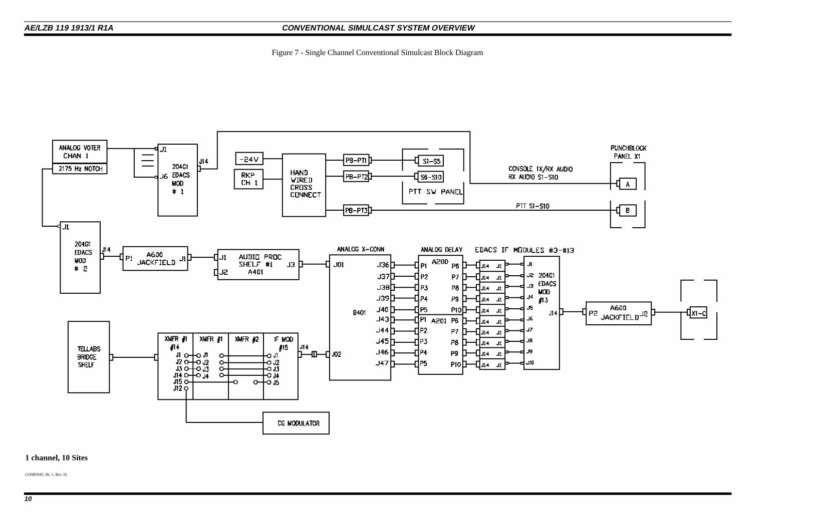
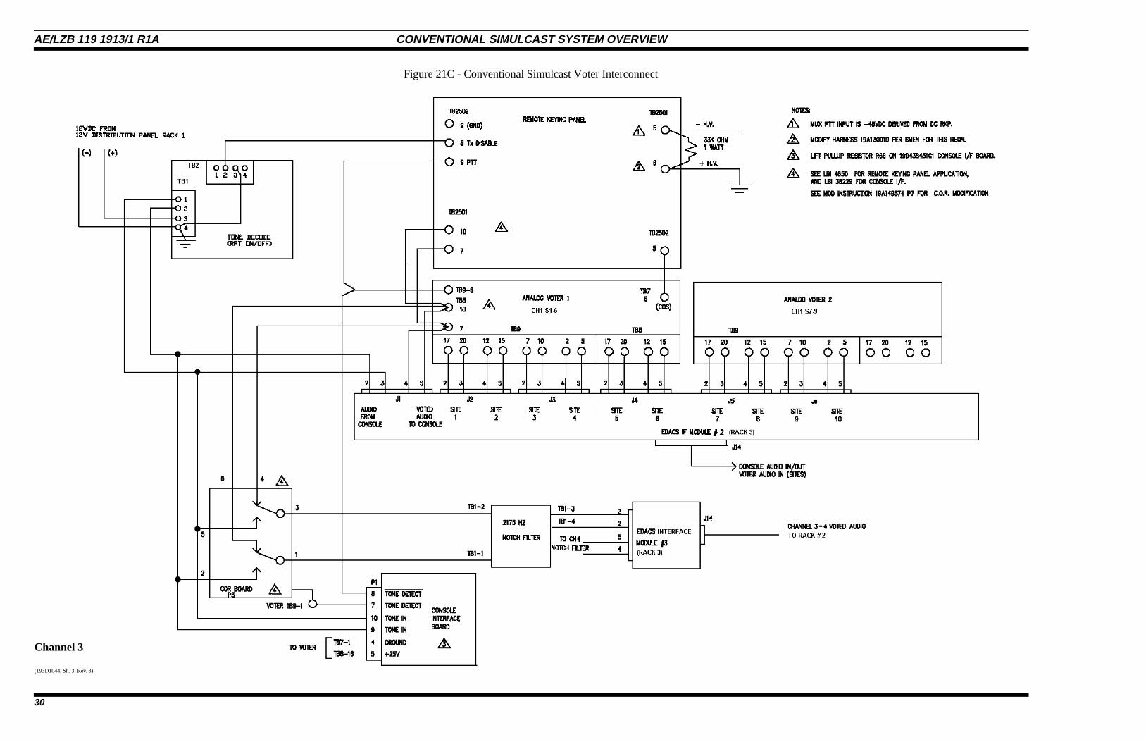
For each standard configuration (1,2 & 4 channel sys-tem) the rack layout, system block diagram, voter intercon-nect, PTT interconnect and power distribution diagrams areshown. The rack layout shows the location of each piece ofequipment in the cabinet/rack for both the front rails and therear rails. Interconnection of all of the pieces of equipmentis shown in the system block diagram providing a means tofollow the signal flow through the entire control point equip-ment. The voter interconnect, the PTT interconnect and thepower distribution diagrams show detail wiring connectionsfor those particular parts of the system.
Transmit Site
Transmit Site Repeater Interconnect Diagrams show in-terconnections among the MASTR III, the EDACS IF Panel,the Audio Bridge Shelf and the reference oscillator. Internalwiring of the MASTR III and the EDACS IF Panel is pro-vided in Instruction Books listed in the Index of Manuals.
CONVENTIONAL SIMULCAST SYSTEM OVERVIEW AE/LZB 119 1913/1 R1A
3
INDEX OF CONVENTIONAL SIMULCAST MAINTENANCE MANUALS
Alignment Procedure . . . . . . . . . . . . . . . . . . . . . . . . . . . . . . . . . . . . . . . . . . . . LBI-39069
Alignment Receiver Radio . . . . . . . . . . . . . . . . . . . . . . . . . . . . . . . . . . . . . . . . . LBI-38494
Analog Control Point . . . . . . . . . . . . . . . . . . . . . . . . . . . . . . . . . . . . . . . . . . . . LBI-38489
Analog Delay Shelf . . . . . . . . . . . . . . . . . . . . . . . . . . . . . . . . . . . . . . . . . . . . . LBI-38990
Analog Delay Module . . . . . . . . . . . . . . . . . . . . . . . . . . . . . . . . . . . . . . . . . . . . LBI-38473
Analog Processing Shelf . . . . . . . . . . . . . . . . . . . . . . . . . . . . . . . . . . . . . . . . . . LBI-38479
Audio Bridge Module . . . . . . . . . . . . . . . . . . . . . . . . . . . . . . . . . . . . . . . . . . . . LBI-38566
Compressor Module . . . . . . . . . . . . . . . . . . . . . . . . . . . . . . . . . . . . . . . . . . . . . Tellabs
PTT Control Panel . . . . . . . . . . . . . . . . . . . . . . . . . . . . . . . . . . . . . . . . . . . . . . LBI-38482
Station Power Supply . . . . . . . . . . . . . . . . . . . . . . . . . . . . . . . . . . . . . . . . . . . . LBI-38550
Simulcast Cross Connect . . . . . . . . . . . . . . . . . . . . . . . . . . . . . . . . . . . . . . . . . . LBI-38580
Voting Selector Panel . . . . . . . . . . . . . . . . . . . . . . . . . . . . . . . . . . . . . . . . . . . . LBI-38676
Console Interface Board . . . . . . . . . . . . . . . . . . . . . . . . . . . . . . . . . . . . . . . . . . . LBI-38229
Connectorized Jackfields . . . . . . . . . . . . . . . . . . . . . . . . . . . . . . . . . . . . . . . . . . ADCP-70-022
WWVB Ref Oscillator . . . . . . . . . . . . . . . . . . . . . . . . . . . . . . . . . . . . . . . . . . . Model 8165
WWVB Loop Ant . . . . . . . . . . . . . . . . . . . . . . . . . . . . . . . . . . . . . . . . . . . . . . Model 8206
EDACS IF Panel . . . . . . . . . . . . . . . . . . . . . . . . . . . . . . . . . . . . . . . . . . . . . . . LBI-38812
EDACS IF Module . . . . . . . . . . . . . . . . . . . . . . . . . . . . . . . . . . . . . . . . . . . . . LBI-38813
MSC II Power Supplies . . . . . . . . . . . . . . . . . . . . . . . . . . . . . . . . . . . . . . . . . . . LBI-38670
Remote Keying Panel . . . . . . . . . . . . . . . . . . . . . . . . . . . . . . . . . . . . . . . . . . . . LBI-4650
EDACS RIC Module . . . . . . . . . . . . . . . . . . . . . . . . . . . . . . . . . . . . . . . . . . . . LBI-38947
AE/LZB 119 1913/1 R1A CONVENTIONAL SIMULCAST SYSTEM OVERVIEW
4
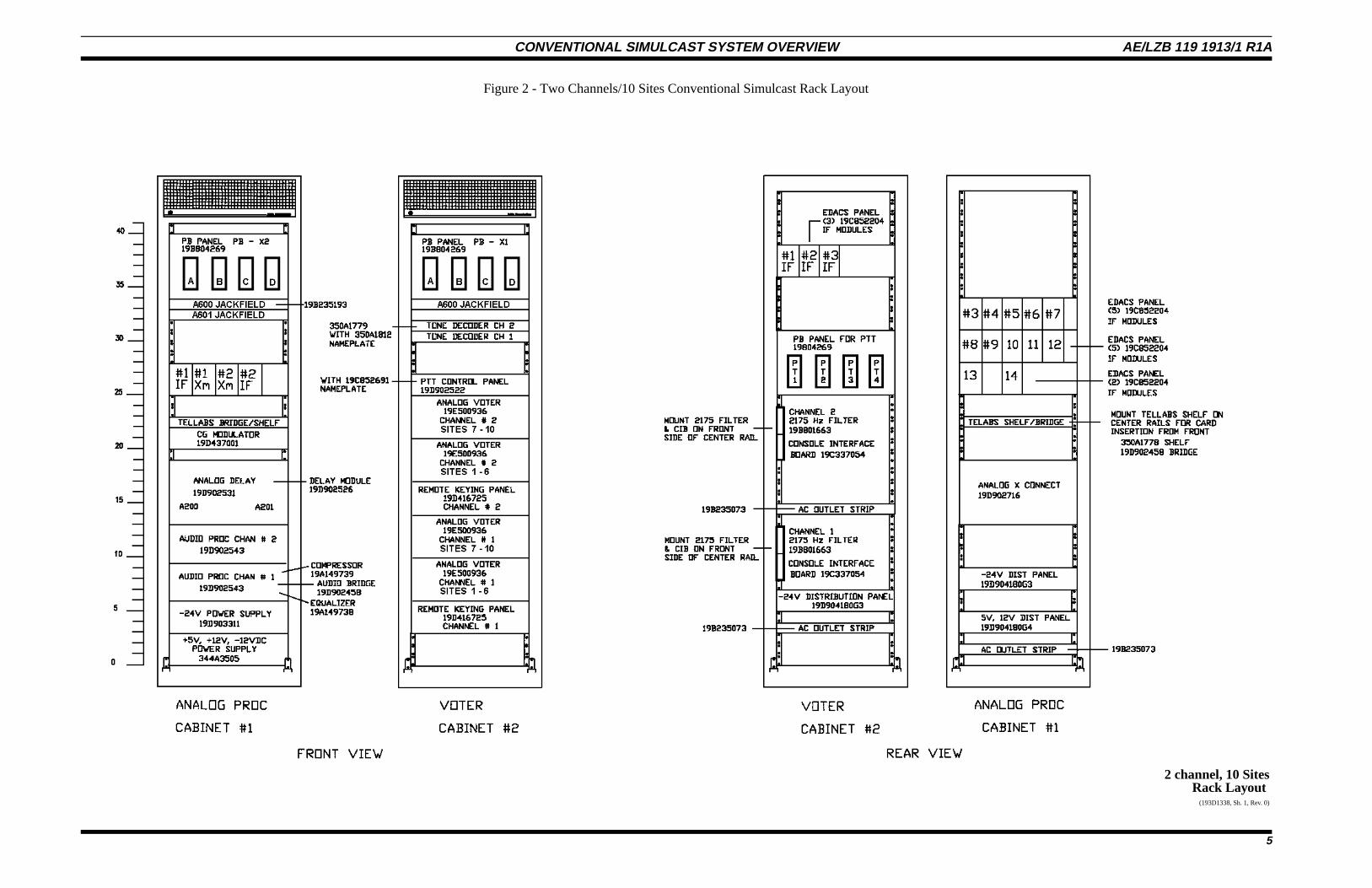
2 channel, 10 SitesRack Layout
(193D1338, Sh. 1, Rev. 0)
Figure 2 - Two Channels/10 Sites Conventional Simulcast Rack Layout
CONVENTIONAL SIMULCAST SYSTEM OVERVIEW AE/LZB 119 1913/1 R1A
5
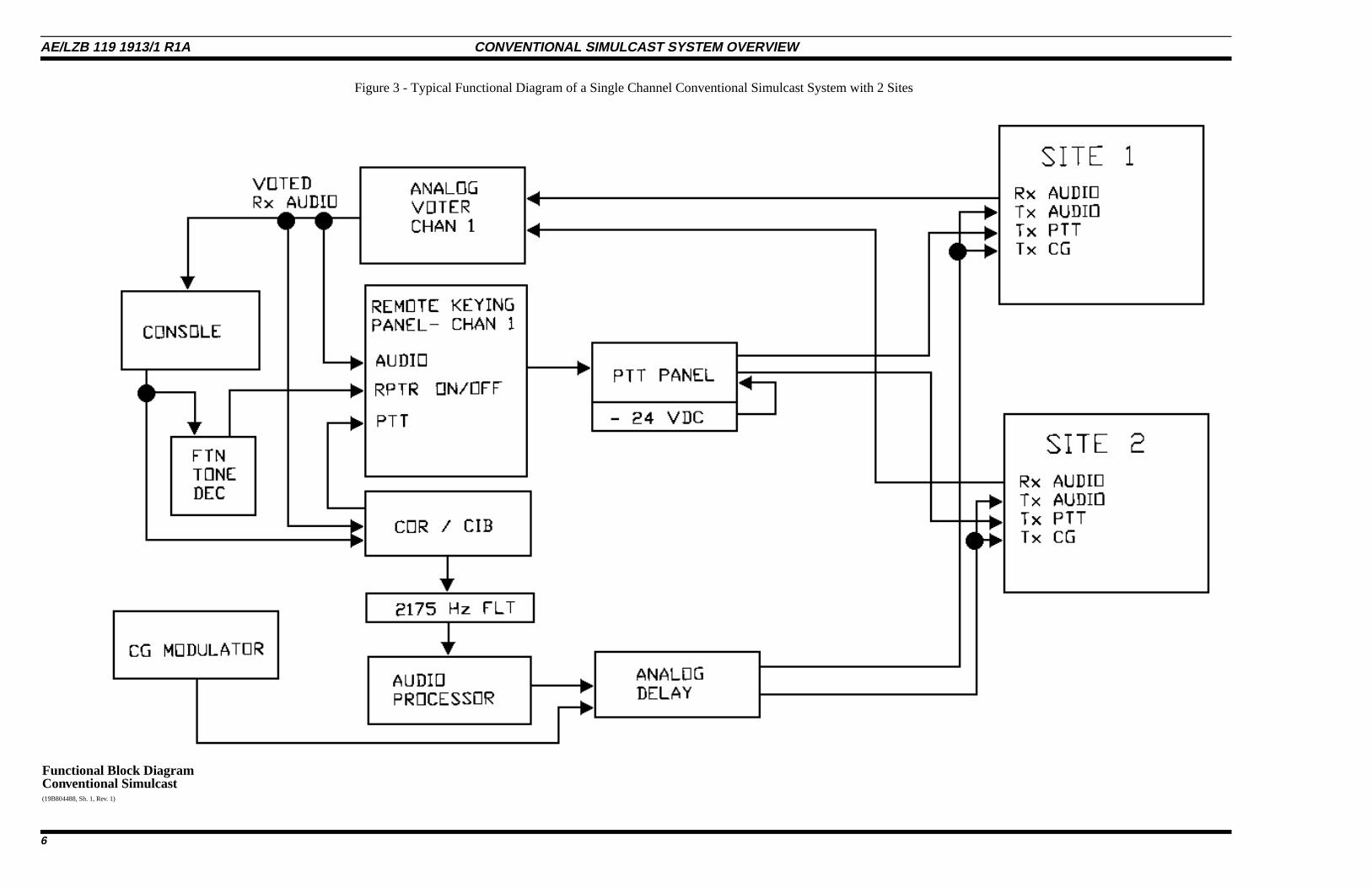
Functional Block DiagramConventional Simulcast(19B804488, Sh. 1, Rev. 1)
Figure 3 - Typical Functional Diagram of a Single Channel Conventional Simulcast System with 2 Sites
AE/LZB 119 1913/1 R1A CONVENTIONAL SIMULCAST SYSTEM OVERVIEW
6
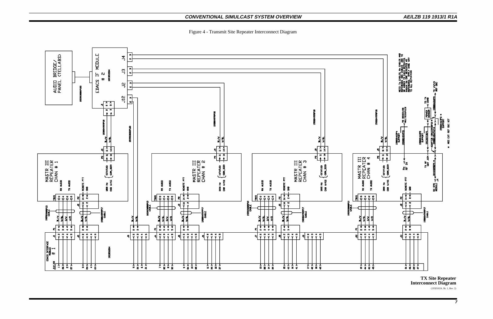
TX Site RepeaterInterconnect Diagram
(193D1024, Sh. 1, Rev. 2)
Figure 4 - Transmit Site Repeater Interconnect Diagram
CONVENTIONAL SIMULCAST SYSTEM OVERVIEW AE/LZB 119 1913/1 R1A
7
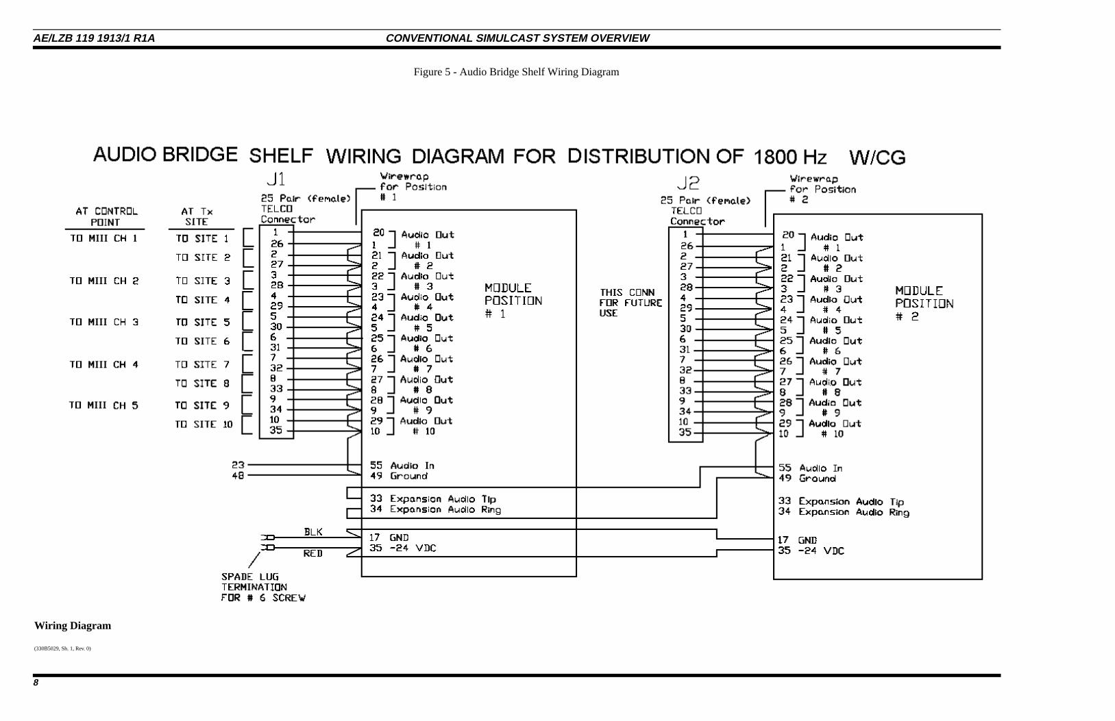
Wiring Diagram
(330B5029, Sh. 1, Rev. 0)
Figure 5 - Audio Bridge Shelf Wiring Diagram
AE/LZB 119 1913/1 R1A CONVENTIONAL SIMULCAST SYSTEM OVERVIEW
8

1 channel, 10 SitesRack Layout
(193D1367, Sh. 1, Rev. 0)
Figure 6 - Conventional Simulcast Rack Layout
CONVENTIONAL SIMULCAST SYSTEM OVERVIEW AE/LZB 119 1913/1 R1A
9
1 channel, 10 Sites
(330B5045, Sh. 1, Rev. 0)
Figure 7 - Single Channel Conventional Simulcast Block Diagram
AE/LZB 119 1913/1 R1A CONVENTIONAL SIMULCAST SYSTEM OVERVIEW
10
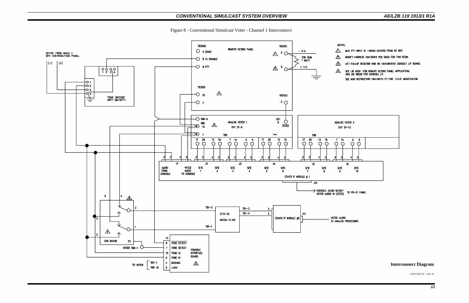
Interconnect Diagram
(193D1368, Sh. 1, Rev. 0)
Figure 8 - Conventional Simulcast Voter - Channel 1 Interconnect
CONVENTIONAL SIMULCAST SYSTEM OVERVIEW AE/LZB 119 1913/1 R1A
11
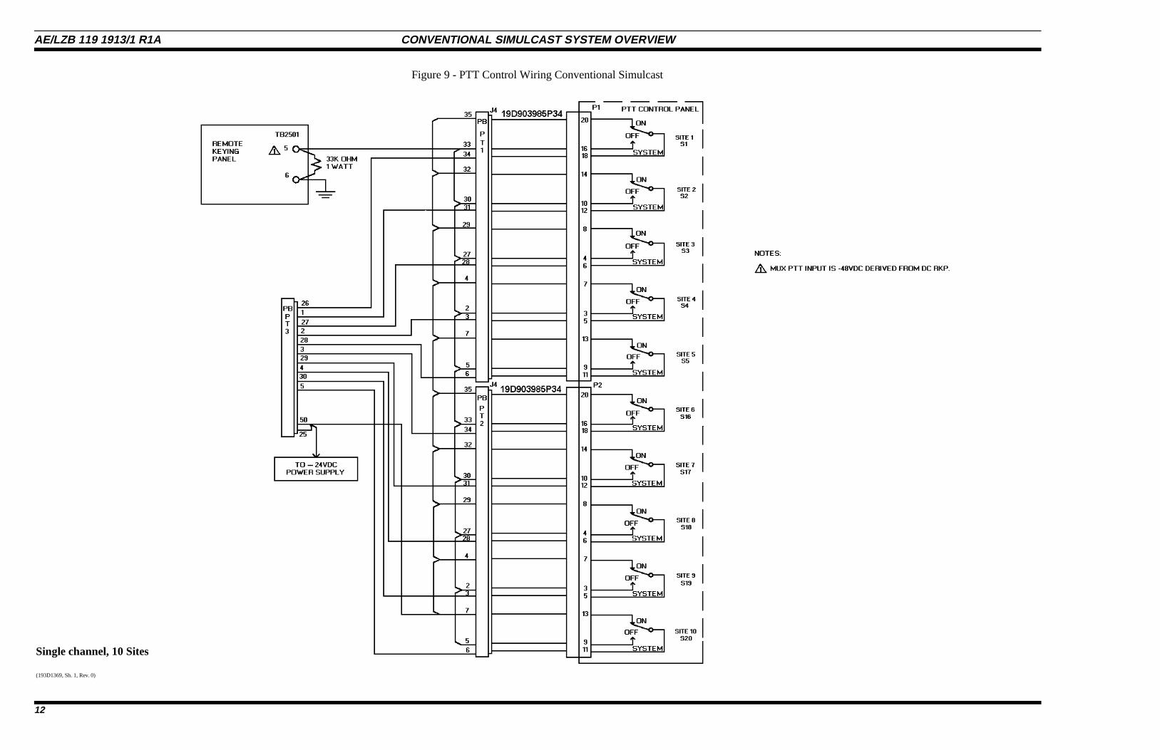
Single channel, 10 Sites
(193D1369, Sh. 1, Rev. 0)
Figure 9 - PTT Control Wiring Conventional Simulcast
AE/LZB 119 1913/1 R1A CONVENTIONAL SIMULCAST SYSTEM OVERVIEW
12
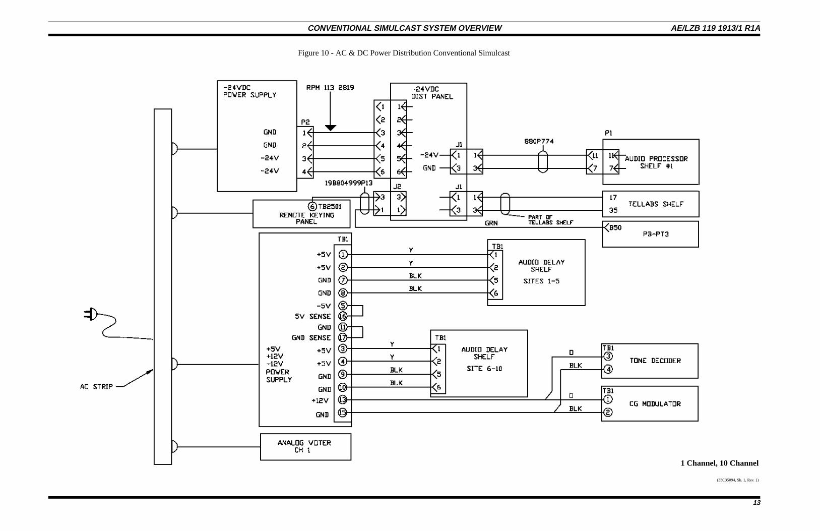
1 Channel, 10 Channel
(330B5094, Sh. 1, Rev. 1)
Figure 10 - AC & DC Power Distribution Conventional Simulcast
CONVENTIONAL SIMULCAST SYSTEM OVERVIEW AE/LZB 119 1913/1 R1A
13
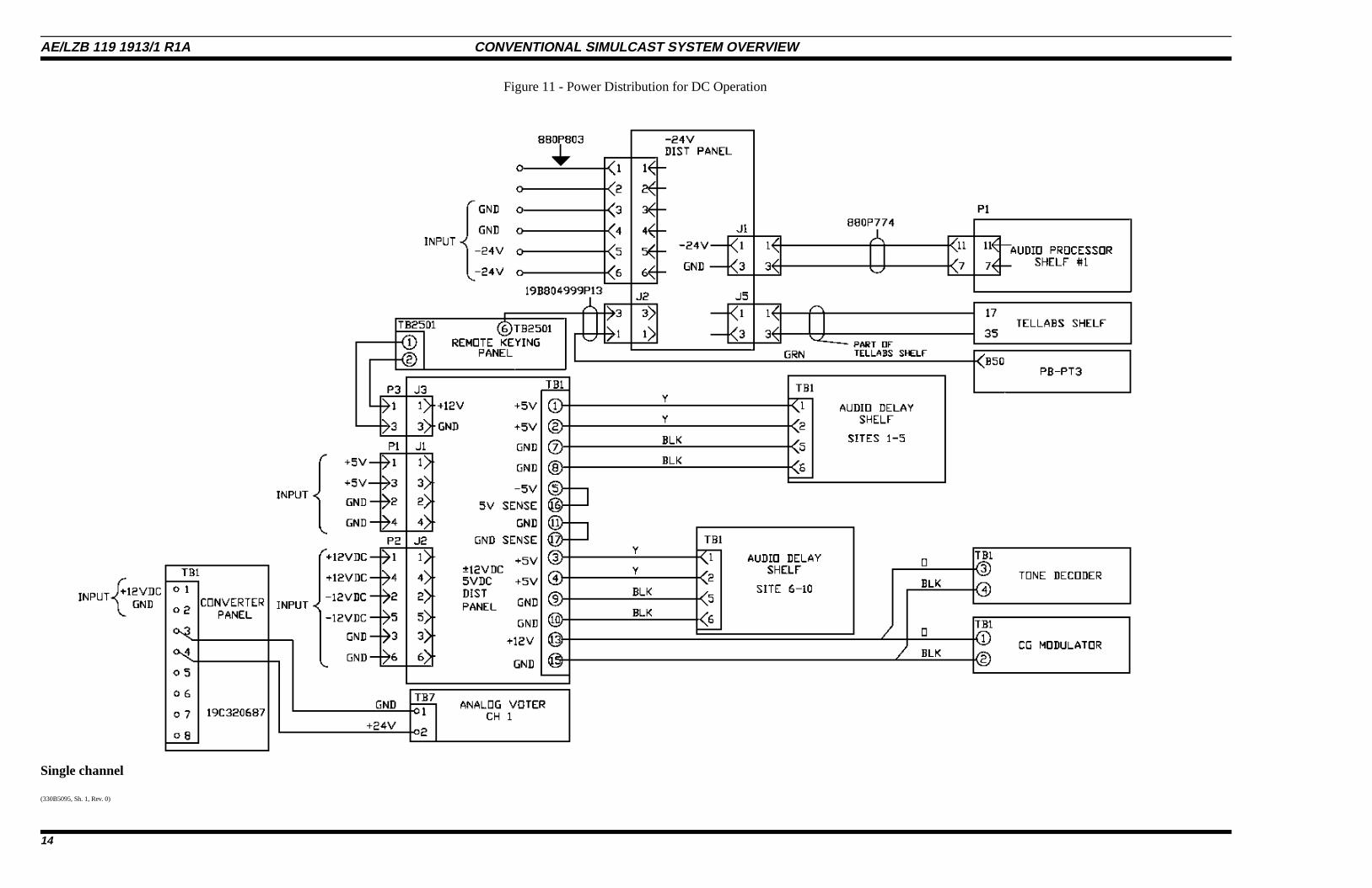
Single channel
(330B5095, Sh. 1, Rev. 0)
Figure 11 - Power Distribution for DC Operation
AE/LZB 119 1913/1 R1A CONVENTIONAL SIMULCAST SYSTEM OVERVIEW
14
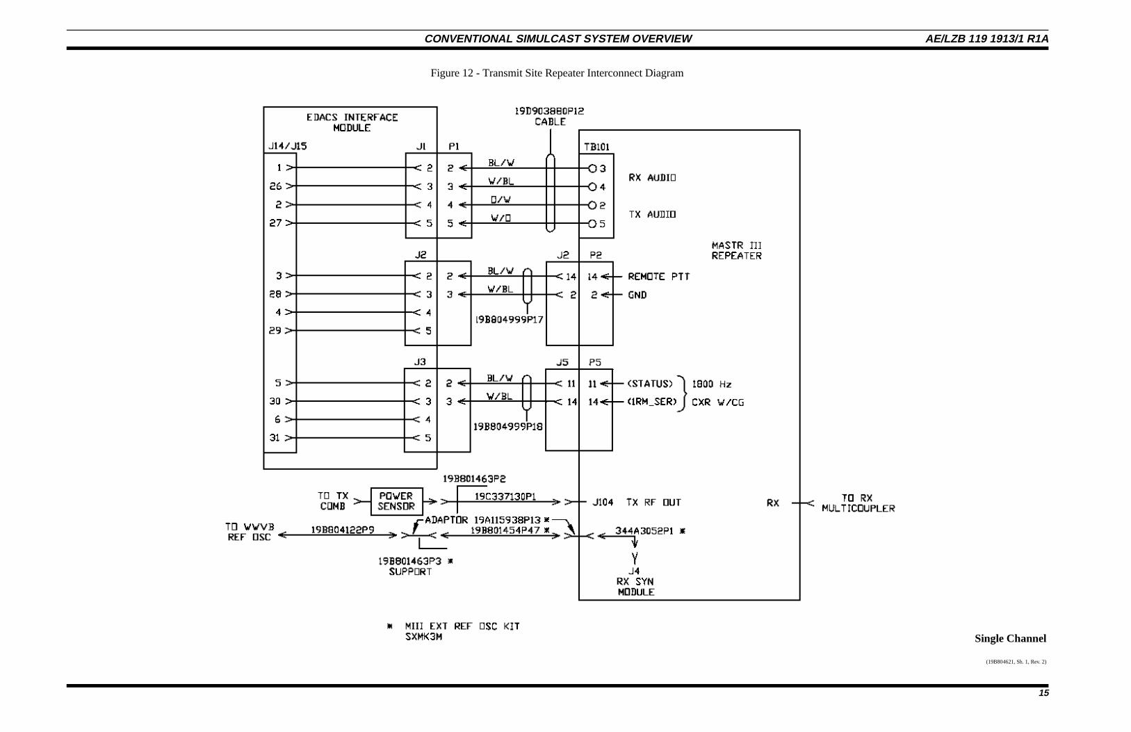
Single Channel
(19B804621, Sh. 1, Rev. 2)
Figure 12 - Transmit Site Repeater Interconnect Diagram
CONVENTIONAL SIMULCAST SYSTEM OVERVIEW AE/LZB 119 1913/1 R1A
15
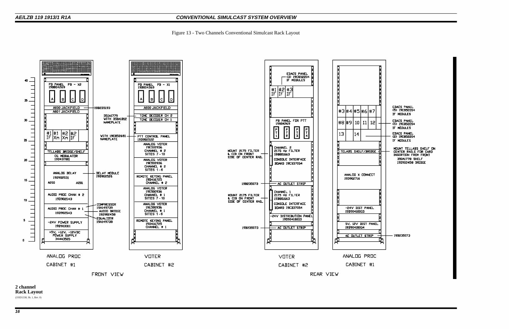
2 channelRack Layout (193D1338, Sh. 1, Rev. 0)
Figure 13 - Two Channels Conventional Simulcast Rack Layout
AE/LZB 119 1913/1 R1A CONVENTIONAL SIMULCAST SYSTEM OVERVIEW
16
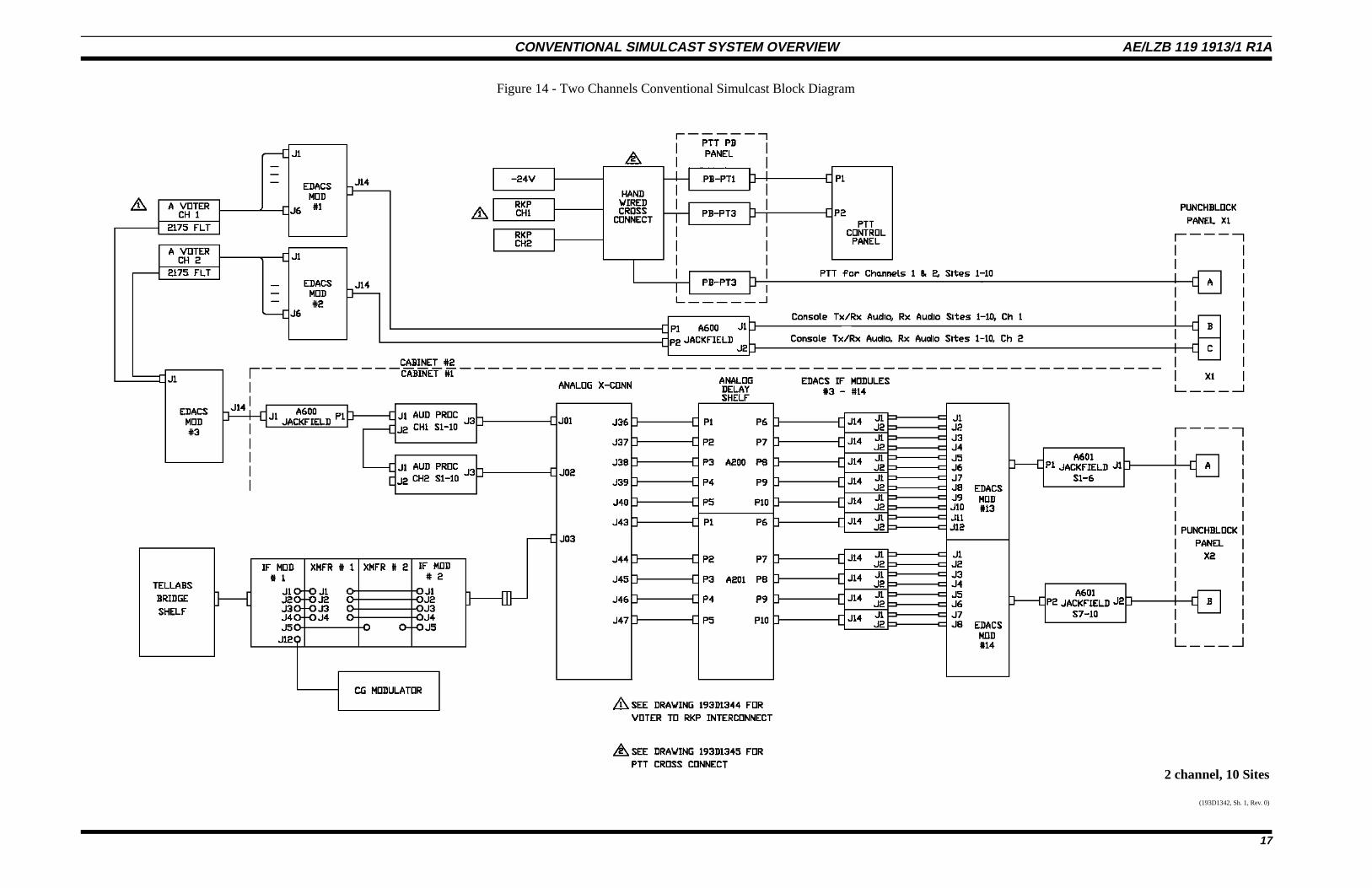
2 channel, 10 Sites
(193D1342, Sh. 1, Rev. 0)
Figure 14 - Two Channels Conventional Simulcast Block Diagram
CONVENTIONAL SIMULCAST SYSTEM OVERVIEW AE/LZB 119 1913/1 R1A
17
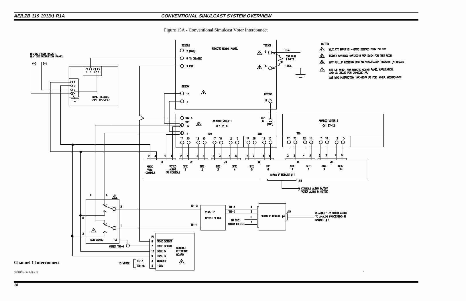
Channel 1 Interconnect
(193D1344, Sh. 1, Rev. 0)
Figure 15A - Conventional Simulcast Voter Interconnect
AE/LZB 119 1913/1 R1A CONVENTIONAL SIMULCAST SYSTEM OVERVIEW
18
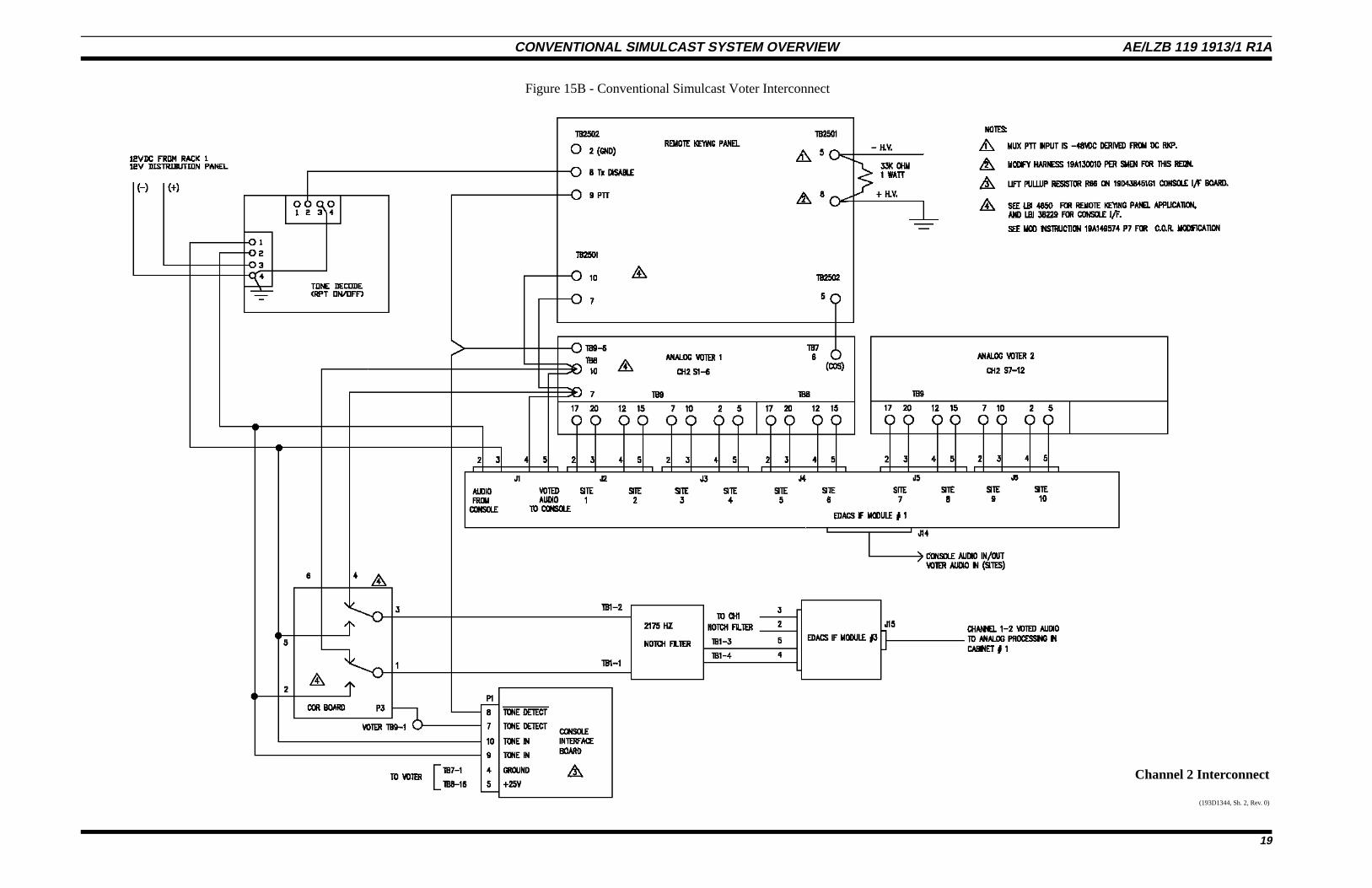
Channel 2 Interconnect
(193D1344, Sh. 2, Rev. 0)
Figure 15B - Conventional Simulcast Voter Interconnect
CONVENTIONAL SIMULCAST SYSTEM OVERVIEW AE/LZB 119 1913/1 R1A
19
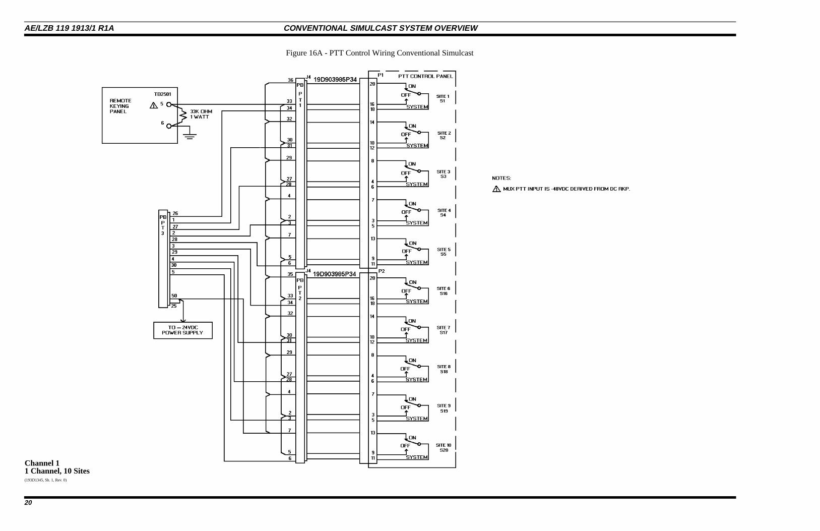
Channel 11 Channel, 10 Sites(193D1345, Sh. 1, Rev. 0)
Figure 16A - PTT Control Wiring Conventional Simulcast
AE/LZB 119 1913/1 R1A CONVENTIONAL SIMULCAST SYSTEM OVERVIEW
20
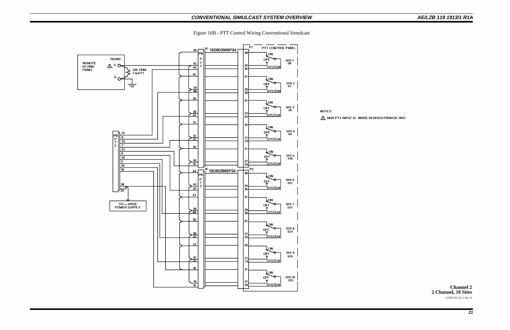
Channel 22 Channel, 10 Sites
(193D1345, Sh. 2, Rev. 0)
Figure 16B - PTT Control Wiring Conventional Simulcast
CONVENTIONAL SIMULCAST SYSTEM OVERVIEW AE/LZB 119 1913/1 R1A
21
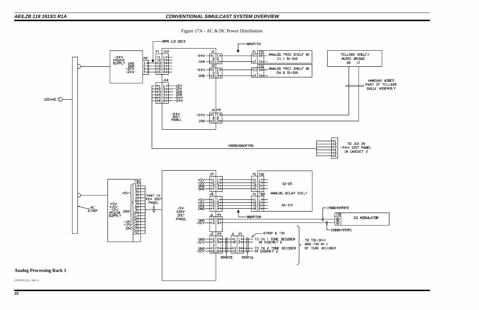
Analog Processing Rack 1
(193D1343, Sh. 1, Rev. 1)
Figure 17A - AC & DC Power Distribution
AE/LZB 119 1913/1 R1A CONVENTIONAL SIMULCAST SYSTEM OVERVIEW
22
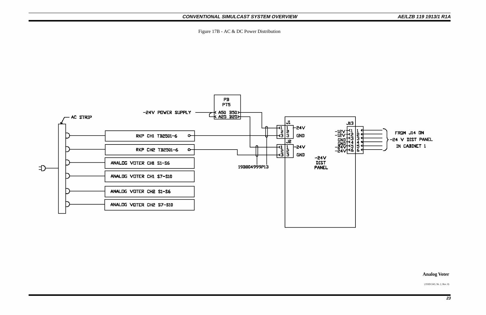
Analog Voter
(193D1343, Sh. 2, Rev. 0)
Figure 17B - AC & DC Power Distribution
CONVENTIONAL SIMULCAST SYSTEM OVERVIEW AE/LZB 119 1913/1 R1A
23
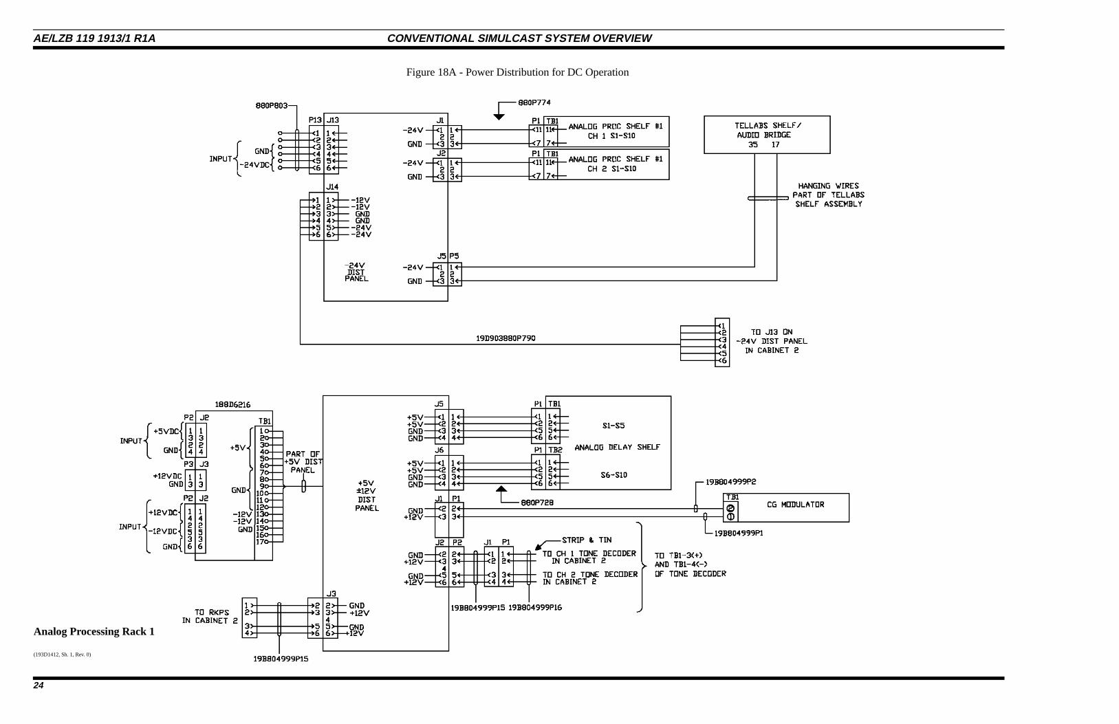
Analog Processing Rack 1
(193D1412, Sh. 1, Rev. 0)
Figure 18A - Power Distribution for DC Operation
AE/LZB 119 1913/1 R1A CONVENTIONAL SIMULCAST SYSTEM OVERVIEW
24
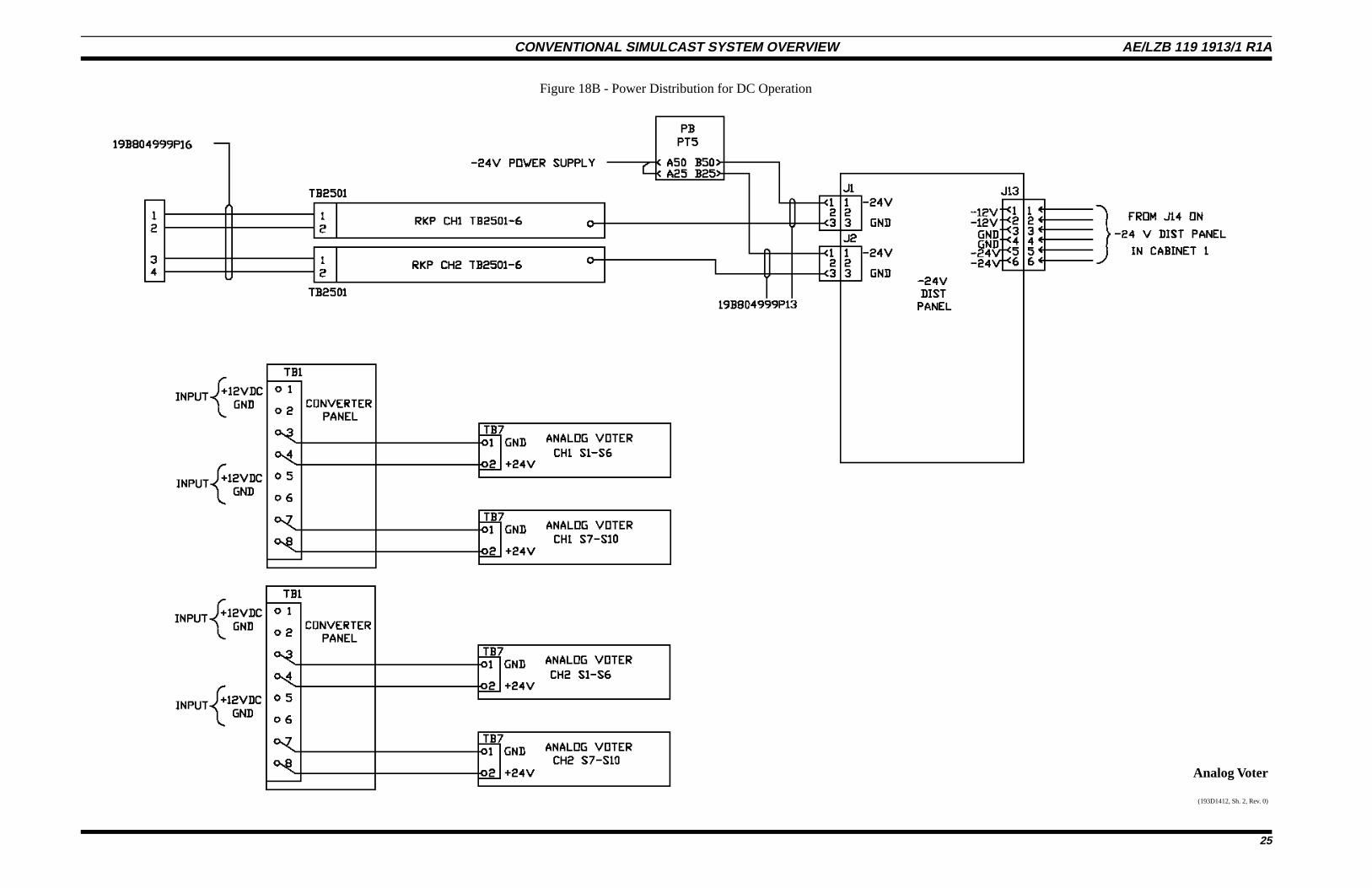
Analog Voter
(193D1412, Sh. 2, Rev. 0)
Figure 18B - Power Distribution for DC Operation
CONVENTIONAL SIMULCAST SYSTEM OVERVIEW AE/LZB 119 1913/1 R1A
25
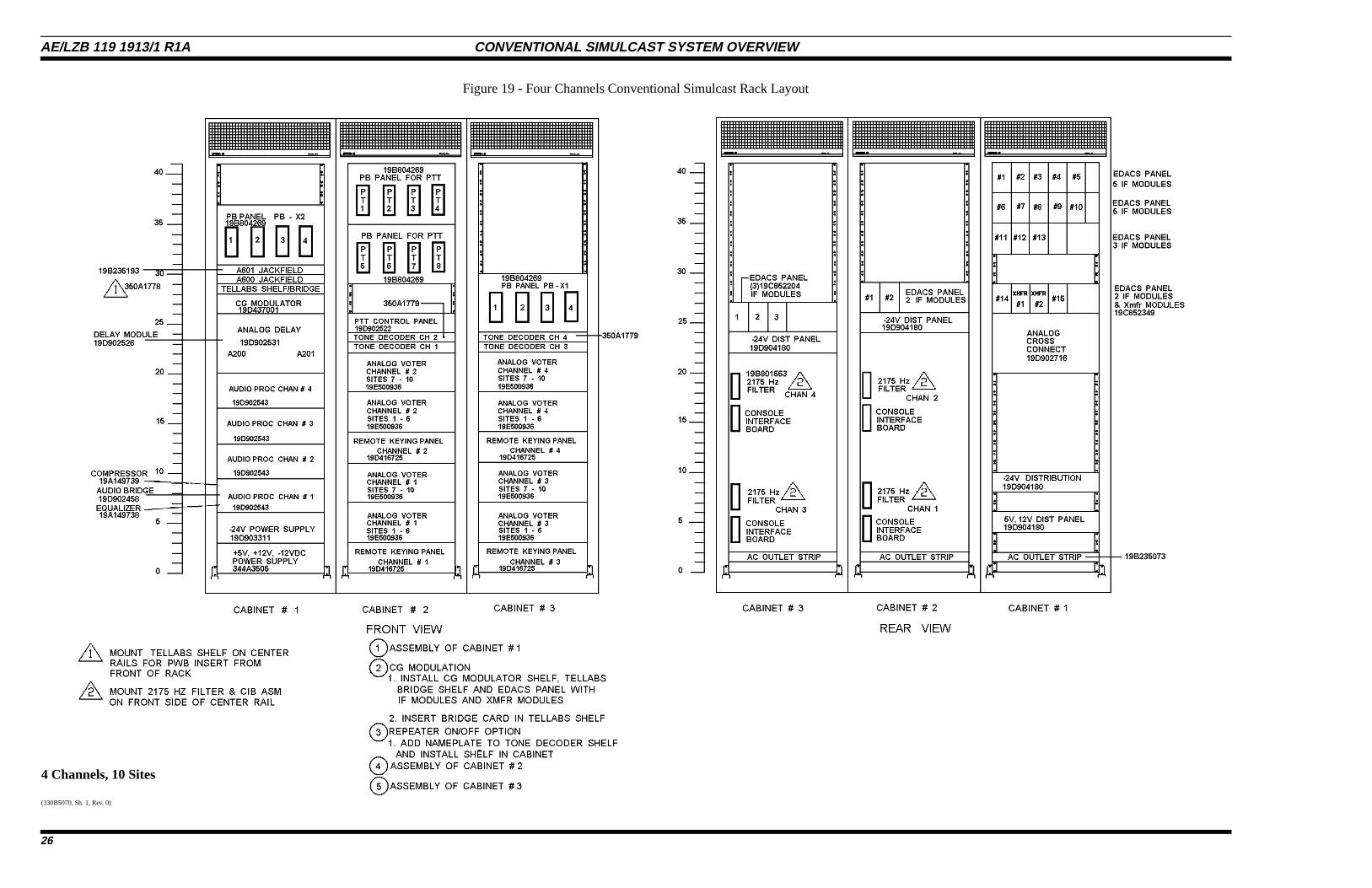
4 Channels, 10 Sites
(330B5070, Sh. 1, Rev. 0)
Figure 19 - Four Channels Conventional Simulcast Rack Layout
AE/LZB 119 1913/1 R1A CONVENTIONAL SIMULCAST SYSTEM OVERVIEW
26
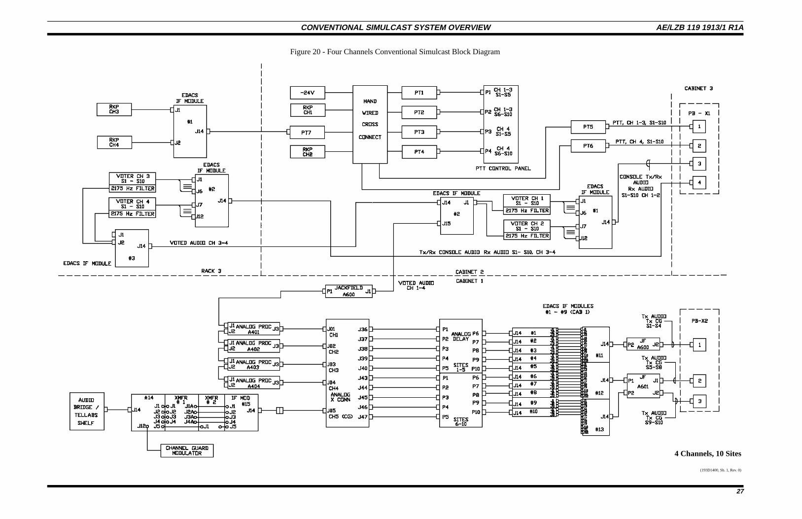
4 Channels, 10 Sites
(193D1400, Sh. 1, Rev. 0)
Figure 20 - Four Channels Conventional Simulcast Block Diagram
CONVENTIONAL SIMULCAST SYSTEM OVERVIEW AE/LZB 119 1913/1 R1A
27
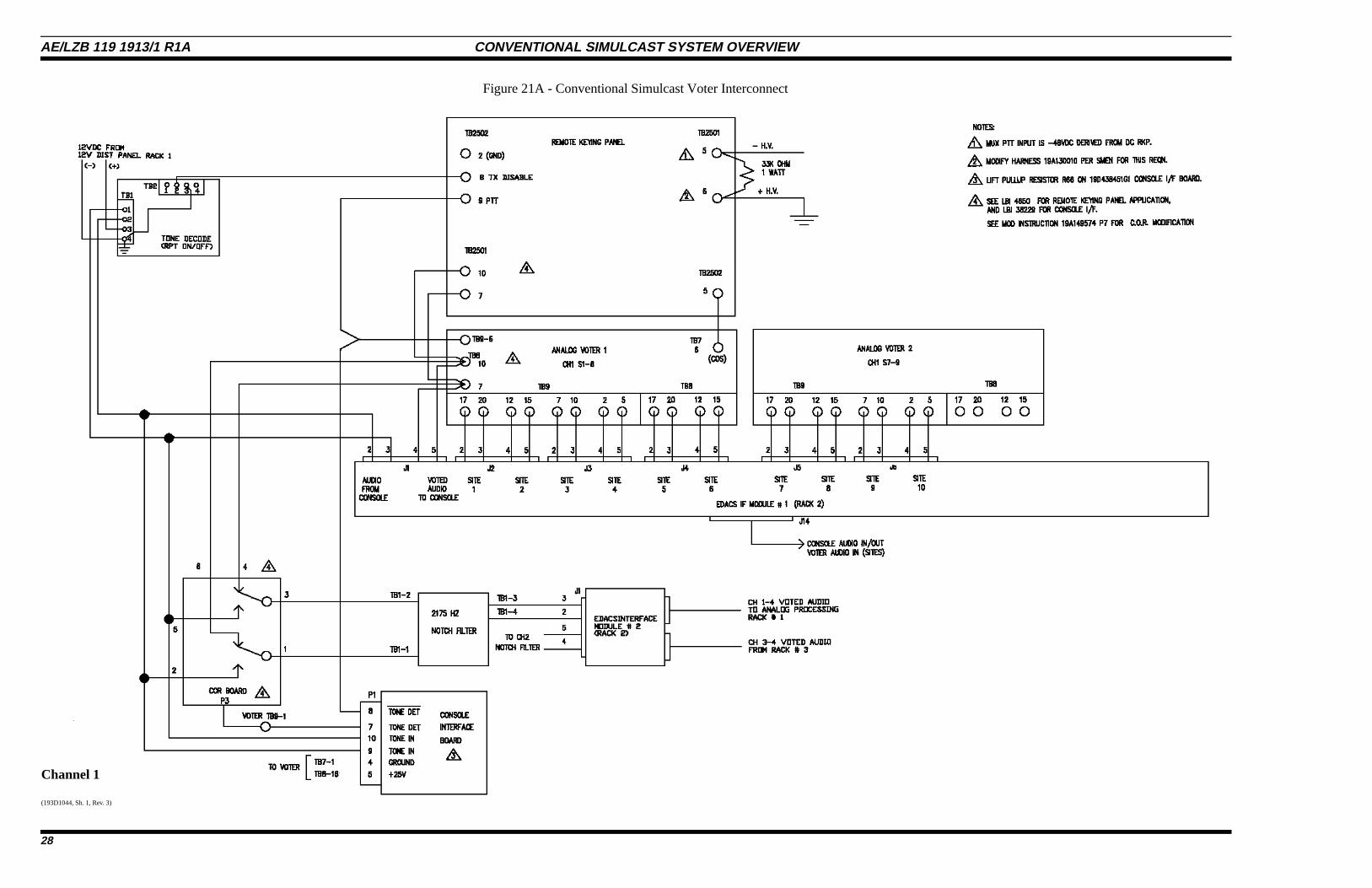
Channel 1
(193D1044, Sh. 1, Rev. 3)
Figure 21A - Conventional Simulcast Voter Interconnect
AE/LZB 119 1913/1 R1A CONVENTIONAL SIMULCAST SYSTEM OVERVIEW
28
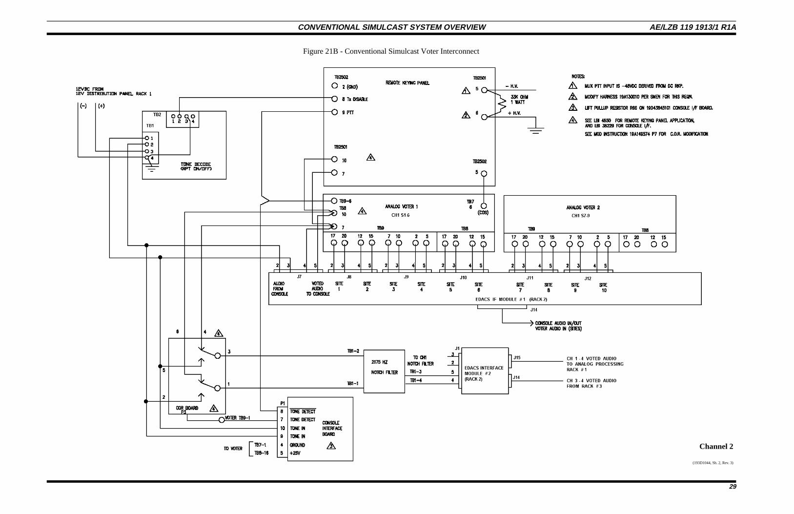
Channel 2
(193D1044, Sh. 2, Rev. 3)
Figure 21B - Conventional Simulcast Voter Interconnect
CONVENTIONAL SIMULCAST SYSTEM OVERVIEW AE/LZB 119 1913/1 R1A
29
Channel 3
(193D1044, Sh. 3, Rev. 3)
Figure 21C - Conventional Simulcast Voter Interconnect
AE/LZB 119 1913/1 R1A CONVENTIONAL SIMULCAST SYSTEM OVERVIEW
30
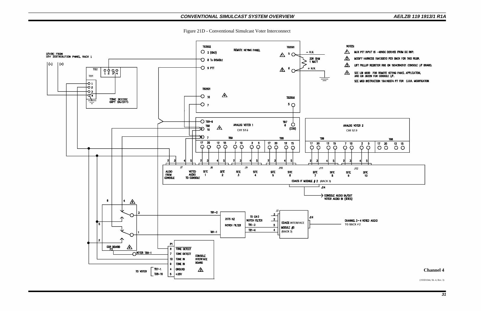
Channel 4
(193D1044, Sh. 4, Rev. 3)
Figure 21D - Conventional Simulcast Voter Interconnect
CONVENTIONAL SIMULCAST SYSTEM OVERVIEW AE/LZB 119 1913/1 R1A
31
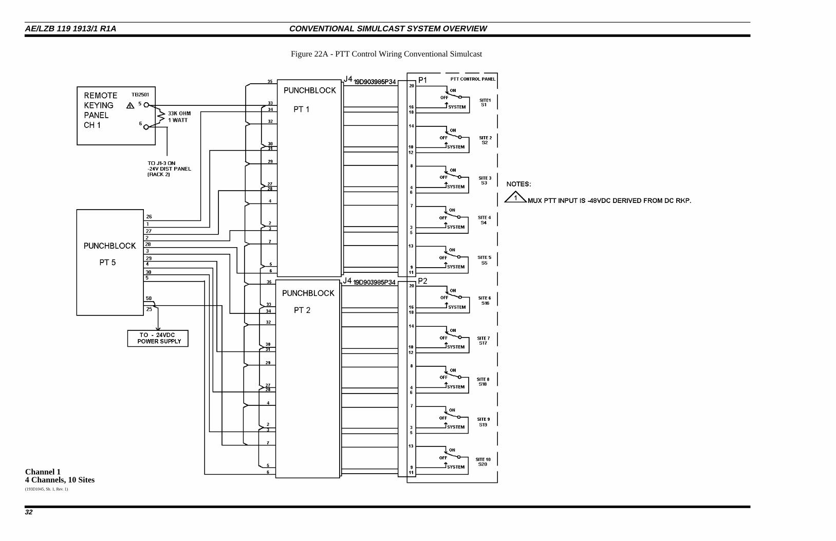
Channel 14 Channels, 10 Sites(193D1045, Sh. 1, Rev. 1)
Figure 22A - PTT Control Wiring Conventional Simulcast
AE/LZB 119 1913/1 R1A CONVENTIONAL SIMULCAST SYSTEM OVERVIEW
32

Channel 24 Channels, 10 Sites
(193D1045, Sh. 2, Rev. 1)
Figure 22B - PTT Control Wiring Conventional Simulcast
CONVENTIONAL SIMULCAST SYSTEM OVERVIEW AE/LZB 119 1913/1 R1A
33
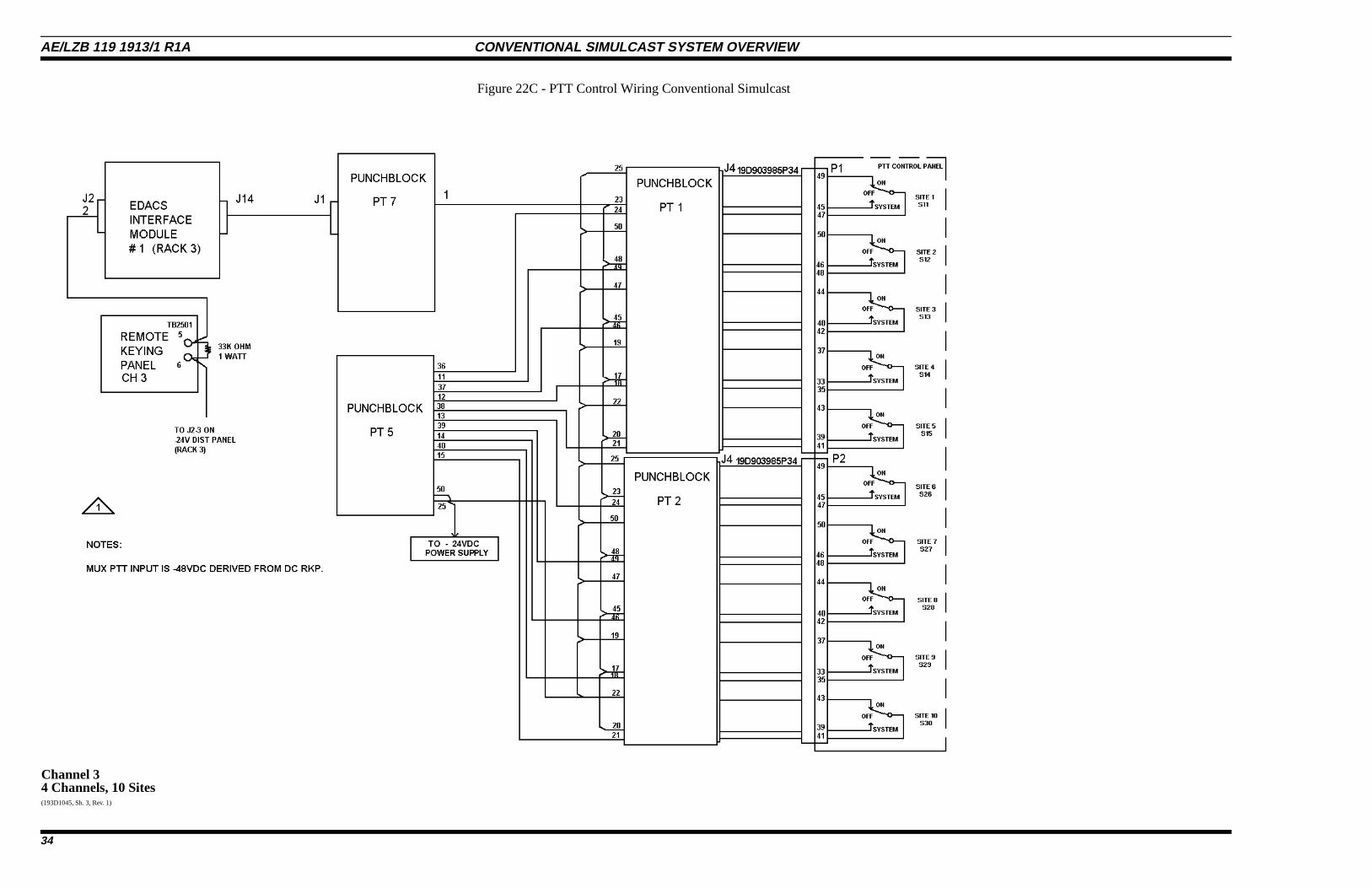
Channel 34 Channels, 10 Sites(193D1045, Sh. 3, Rev. 1)
Figure 22C - PTT Control Wiring Conventional Simulcast
AE/LZB 119 1913/1 R1A CONVENTIONAL SIMULCAST SYSTEM OVERVIEW
34
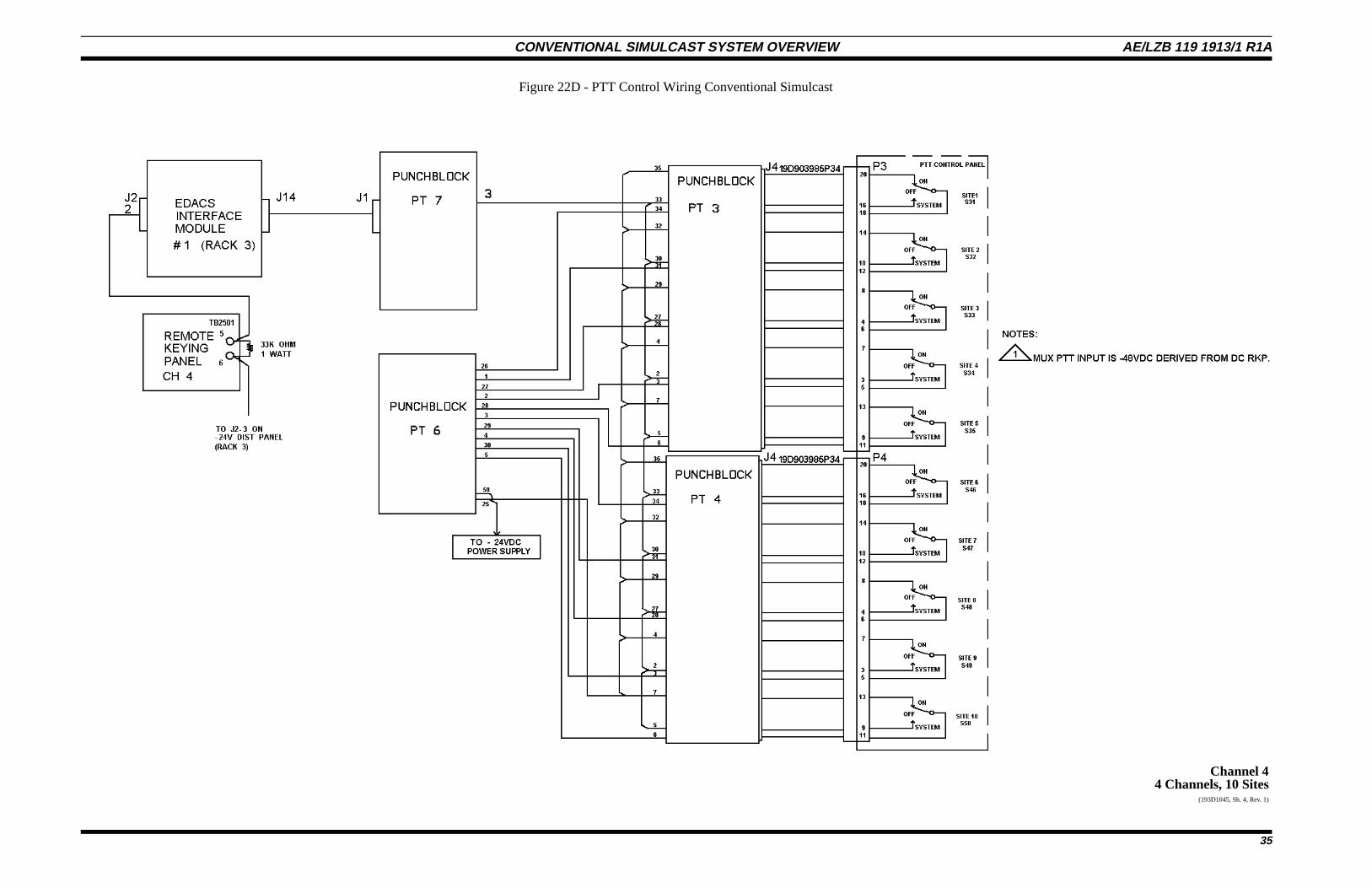
Channel 44 Channels, 10 Sites
(193D1045, Sh. 4, Rev. 1)
Figure 22D - PTT Control Wiring Conventional Simulcast
CONVENTIONAL SIMULCAST SYSTEM OVERVIEW AE/LZB 119 1913/1 R1A
35
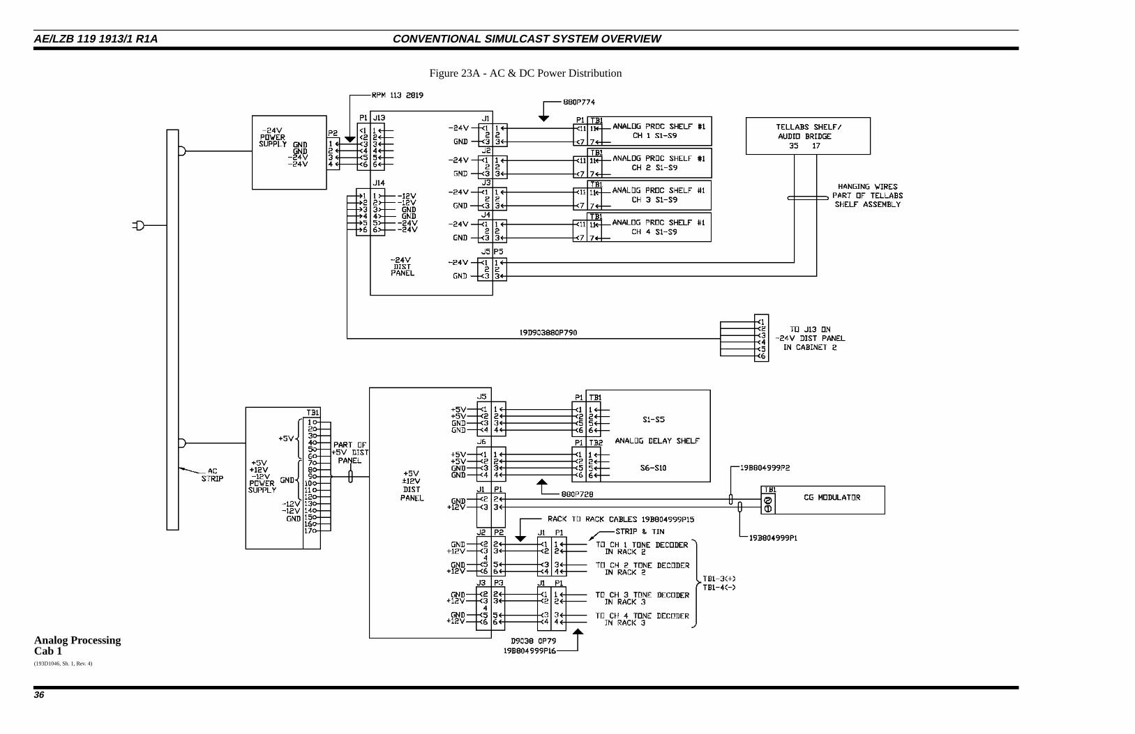
Analog ProcessingCab 1(193D1046, Sh. 1, Rev. 4)
Figure 23A - AC & DC Power Distribution
AE/LZB 119 1913/1 R1A CONVENTIONAL SIMULCAST SYSTEM OVERVIEW
36
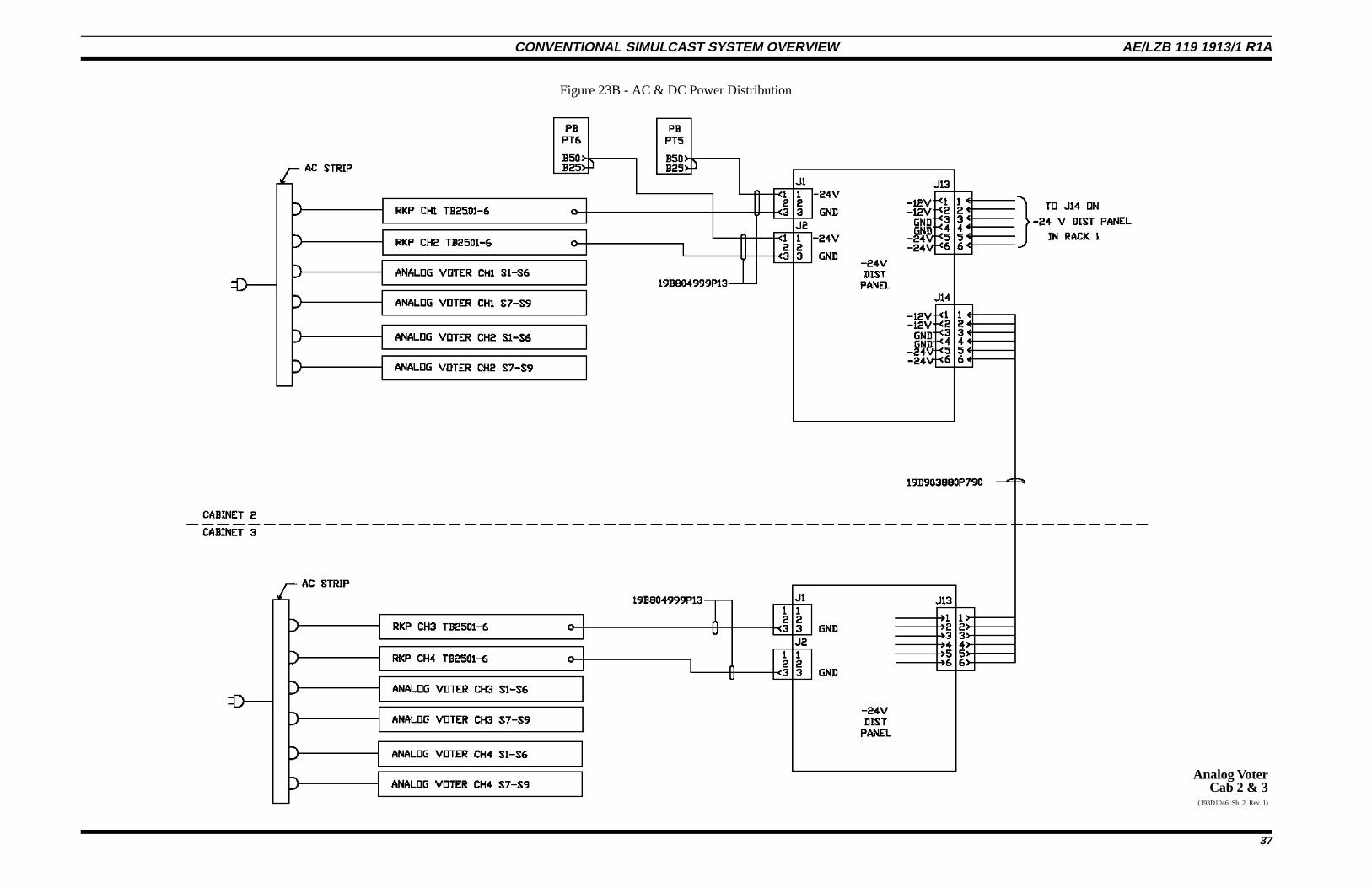
Analog VoterCab 2 & 3
(193D1046, Sh. 2, Rev. 1)
Figure 23B - AC & DC Power Distribution
CONVENTIONAL SIMULCAST SYSTEM OVERVIEW AE/LZB 119 1913/1 R1A
37
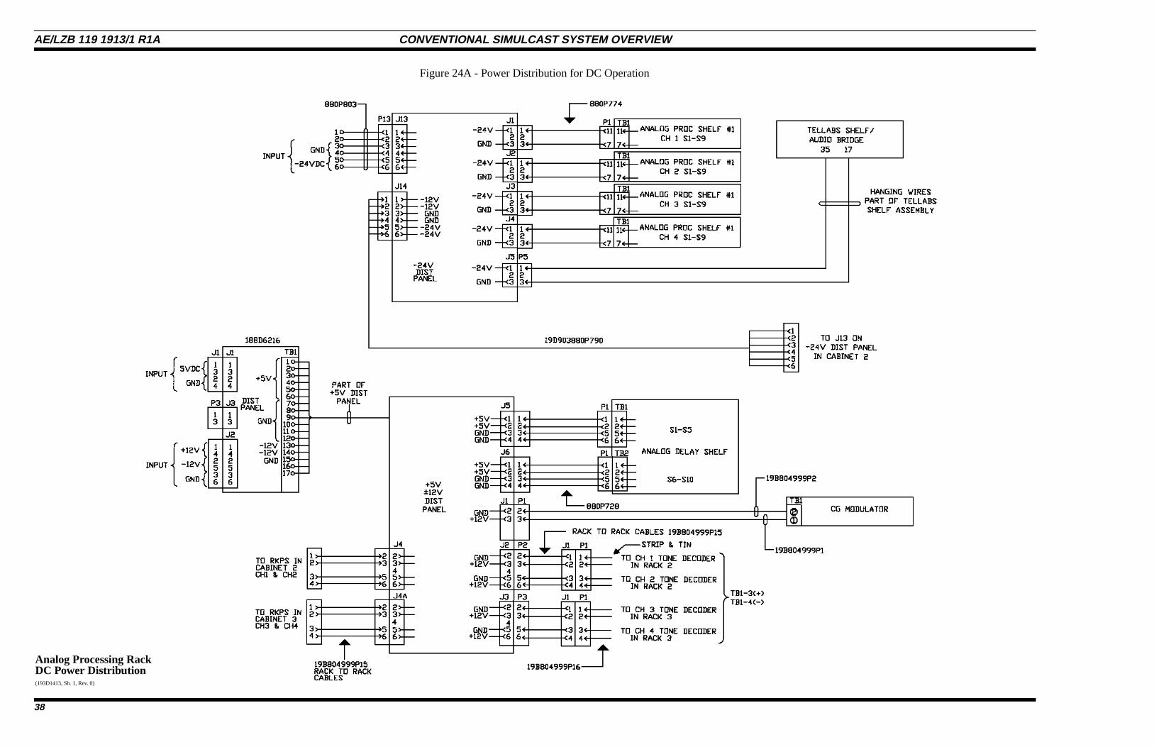
Analog Processing RackDC Power Distribution(193D1413, Sh. 1, Rev. 0)
Figure 24A - Power Distribution for DC Operation
AE/LZB 119 1913/1 R1A CONVENTIONAL SIMULCAST SYSTEM OVERVIEW
38
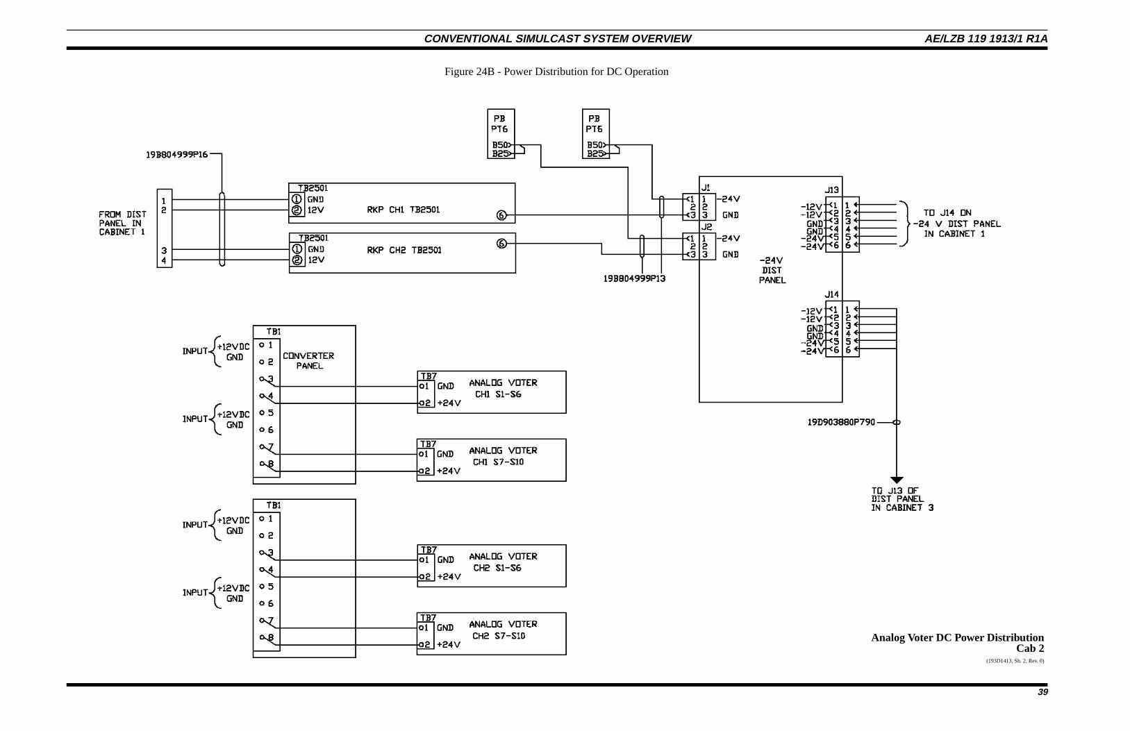
Analog Voter DC Power DistributionCab 2
(193D1413, Sh. 2, Rev. 0)
Figure 24B - Power Distribution for DC Operation
CONVENTIONAL SIMULCAST SYSTEM OVERVIEW AE/LZB 119 1913/1 R1A
39
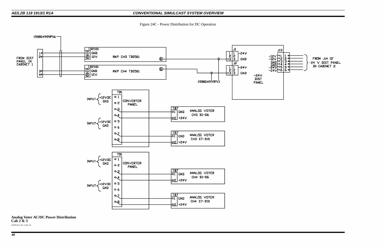
Analog Voter AC/DC Power DistributionCab 2 & 3(193D1413, Sh. 3, Rev. 0)
Figure 24C - Power Distribution for DC Operation
AE/LZB 119 1913/1 R1A CONVENTIONAL SIMULCAST SYSTEM OVERVIEW
40
This page intentionally left blank
CONVENTIONAL SIMULCAST SYSTEM OVERVIEW AE/LZB 119 1913/1 R1A
41


![TaitNet AS-IP Analog Simulcast Conventional Network · TaitNet P25 Conventional Network with TB7300/TB9400 Base Stations for Simulcast . System Overview [Enter Client Name] TD-0037-06[Enter](https://img.pdfslide.us/doc/110x75/5fc05006fd678f36e425c467/taitnet-as-ip-analog-simulcast-conventional-network-taitnet-p25-conventional-network.jpg)