Embed Size (px)
Citation preview

Lufkin Modbus Driver
© 2019 PTC Inc. All Rights Reserved.
Lufkin Modbus Driver
Table of Contents
Lufkin Modbus Driver 1
Table of Contents 2
Lufkin Modbus Driver 4
Overview 4
Channel Setup 4
Channel Properties — General 5
Channel Properties — Serial Communications 6
Channel Properties —Write Optimizations 8
Channel Properties — Advanced 9
Channel Properties — Communication Serialization 9
Device Setup 11
Device Properties — General 11
Operating Mode 12
Device Properties — Scan Mode 12
Device Properties — Tag Generation 13
Device Properties — Timing 15
Device Properties — Auto-Demotion 16
Device Properties — Block Sizes 16
Device Properties — Data Encoding 17
Device Properties — Framing 17
Device Properties — Error Handling 18
Device Properties — Card Settings 19
Device Properties — Redundancy 20
Data Types Description 21
Address Descriptions 21
Statistics Items 24
Error Descriptions 27
Address Validation 27
Address <address> is out of range for the specified device or register. 27
Array size is out of range for address <address>. 27
Array support is not available for the specified address: <address>. 27
Data Type <type> is not valid for device address <address>. 28
Device address <address> contains a syntax error. 28
Device address <address> is not supported by model <model name>. 28
Device address <address> is read only. 28
Missing address 29
Serial Communications 29
COMn does not exist. 29
COMn is in use by another application. 29
Error opening COMn [OS Error == <OS Error ID>]. 29
www.ptc.com
2
Lufkin ModbusDriver
Serial communications error on channel <channel name> [<error mask>]. 30
Unable to set comm parameters on COMn [OS Error == <OS Error ID>]. 30
Device Status Messages 30
Device <device name> is not responding. 30
Unable to write to <address> on device <device name>. 31
Unable to write to address <address> on device <device>: Device responded with exception code<code>. 31
Write failed for <tag name> on device <device name>. Maximum path length of <number>exceeded. 31
Lufkin Modbus Specific Messages 32
Bad address in block [<start address> to <end address>] on device <device name>. 32
Bad array spanning [<address> to <address>] on device <device>. 32
Modbus Exception Codes 33
Index 33
www.ptc.com
3
Lufkin ModbusDriver
Lufkin Modbus DriverHelp version 1.031
CONTENTS
OverviewWhat is the Lufkin Modbus Driver?
Channel SetupHow do I configure channels for use with this driver?
Device SetupHow do I configure a device for use with this driver?
Data Types DescriptionWhat data types does this driver support?
Address DescriptionsHow do I address a data location on a Lufkin Modbus device?
Error DescriptionsWhat error messages are produced by the Lufkin Modbus Driver?
OverviewThe Lufkin Modbus Driver provides a reliable way to connect Lufkin Modbus devices to OPC client applications;including HMI, SCADA, Historian, MES, ERP, and countless custom applications. It intended for use with serialdevices that support the Extended Lufkin Automation Modbus (ELAM) protocol and the Standard MODBUS pro-tocol.
Channel SetupThis driver supports multiple channel properties. For more information, refer to "What is a Channel?" in theserver help file.
MaximumNumber of ChannelsThe maximum number of channels supported by this driver is 1024.
Communication ProtocolExtended Lufkin Automation Modbus (ELAM)Standard Modbus
Supported Communication PropertiesBaud Rate: All major Baud rates.Parity: Odd, Even, and None.Data Bits: 5, 6, 7 and 8.Stop Bits: 1 and 2.
Note:Not all of the listed configurations may be supported in every device.
Flow ControlWhen using an RS232/RS485 converter, the type of flow control that is required depends on the converter'sneeds. Some do not require any flow control whereas others require RTS flow. Consult the converter's doc-umentation to determine its flow requirements. An RS485 converter that provides automatic flow control isrecommended.
www.ptc.com
4
Lufkin Modbus Driver
Note:When using the manufacturer's supplied communications cable, it is sometimes necessary to choose aflow control setting of RTS or RTS Always in Channel Properties.
Manual Flow ControlThe Lufkin Modbus Driver supports RTS Manual flow control, which is used to configure the driver for operationwith radio modems that require special RTS timing characteristics. For more information, refer to the server'shelp documentation.
Ethernet EncapsulationThis driver supports Ethernet Encapsulation, which allows the driver to communicate with serial devicesattached to an Ethernet network using a terminal server. It may be enabled for the channel through the SerialCommunications properties in Channel Properties. For more information, refer to the server help file.
Communication SerializationThe Lufkin Modbus Driver supports Communication Serialization, which specifies whether data transmissionsshould be limited to one channel at a time. For more information, refer to "Channel Properties — Advanced" inthe server help file.
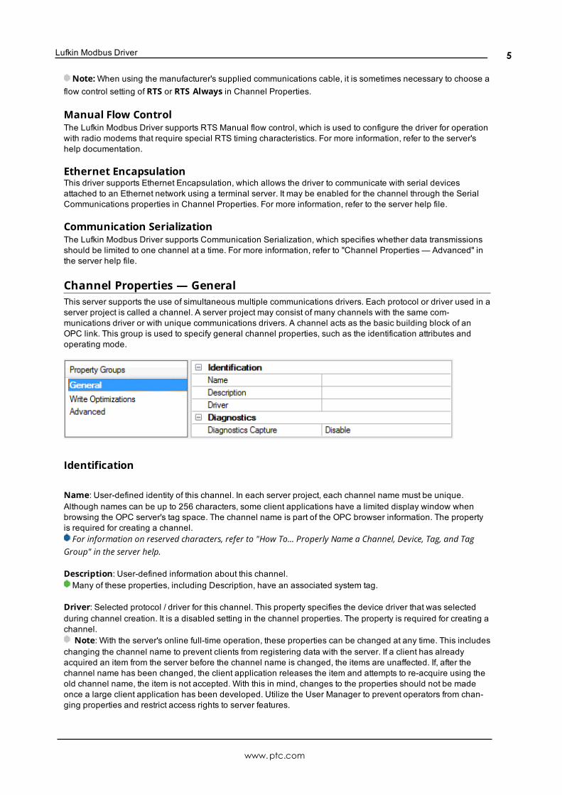
Channel Properties — GeneralThis server supports the use of simultaneous multiple communications drivers. Each protocol or driver used in aserver project is called a channel. A server project may consist of many channels with the same com-munications driver or with unique communications drivers. A channel acts as the basic building block of anOPC link. This group is used to specify general channel properties, such as the identification attributes andoperating mode.
Identification
Name: User-defined identity of this channel. In each server project, each channel name must be unique.Although names can be up to 256 characters, some client applications have a limited display window whenbrowsing the OPC server's tag space. The channel name is part of the OPC browser information. The propertyis required for creating a channel.For information on reserved characters, refer to "How To... Properly Name a Channel, Device, Tag, and Tag
Group" in the server help.
Description: User-defined information about this channel. Many of these properties, including Description, have an associated system tag.
Driver: Selected protocol / driver for this channel. This property specifies the device driver that was selectedduring channel creation. It is a disabled setting in the channel properties. The property is required for creating achannel.
Note: With the server's online full-time operation, these properties can be changed at any time. This includeschanging the channel name to prevent clients from registering data with the server. If a client has alreadyacquired an item from the server before the channel name is changed, the items are unaffected. If, after thechannel name has been changed, the client application releases the item and attempts to re-acquire using theold channel name, the item is not accepted. With this in mind, changes to the properties should not be madeonce a large client application has been developed. Utilize the User Manager to prevent operators from chan-ging properties and restrict access rights to server features.
www.ptc.com
5
Lufkin ModbusDriver
Diagnostics
Diagnostics Capture: When enabled, this option makes the channel's diagnostic information available to OPCapplications. Because the server's diagnostic features require a minimal amount of overhead processing, it isrecommended that they be utilized when needed and disabled when not. The default is disabled.Note: This property is not available if the driver does not support diagnostics.For more information, refer to "Communication Diagnostics" in the server help.
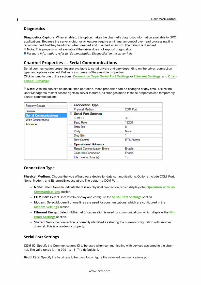
Channel Properties — Serial CommunicationsSerial communication properties are available to serial drivers and vary depending on the driver, connectiontype, and options selected. Below is a superset of the possible properties.Click to jump to one of the sections: Connection Type, Serial Port Settings or Ethernet Settings, and Oper-ational Behavior.
Note: With the server's online full-time operation, these properties can be changed at any time. Utilize theUser Manager to restrict access rights to server features, as changes made to these properties can temporarilydisrupt communications.
Connection Type
Physical Medium: Choose the type of hardware device for data communications. Options include COM Port,None, Modem, and Ethernet Encapsulation. The default is COM Port.
l None: Select None to indicate there is no physical connection, which displays the Operation with noCommunications section.
l COM Port: Select Com Port to display and configure the Serial Port Settings section.l Modem: Select Modem if phone lines are used for communications, which are configured in the
Modem Settings section.l Ethernet Encap.: Select if Ethernet Encapsulation is used for communications, which displays the Eth-
ernet Settings section.l Shared: Verify the connection is correctly identified as sharing the current configuration with anotherchannel. This is a read-only property.
Serial Port Settings
COM ID: Specify the Communications ID to be used when communicating with devices assigned to the chan-nel. The valid range is 1 to 9991 to 16. The default is 1.
Baud Rate: Specify the baud rate to be used to configure the selected communications port.
www.ptc.com
6
Lufkin Modbus Driver
Data Bits: Specify the number of data bits per data word. Options include 5, 6, 7, or 8.
Parity: Specify the type of parity for the data. Options include Odd, Even, or None.
Stop Bits: Specify the number of stop bits per data word. Options include 1 or 2.
Flow Control: Select how the RTS and DTR control lines are utilized. Flow control is required to communicatewith some serial devices. Options are:
l None: This option does not toggle or assert control lines.l DTR: This option asserts the DTR line when the communications port is opened and remains on.
l RTS: This option specifies that the RTS line is high if bytes are available for transmission. After all buf-fered bytes have been sent, the RTS line is low. This is normally used with RS232/RS485 converterhardware.
l RTS, DTR: This option is a combination of DTR and RTS.
l RTS Always: This option asserts the RTS line when the communication port is opened and remains on.
l RTS Manual: This option asserts the RTS line based on the timing properties entered for RTS Line Con-trol. It is only available when the driver supports manual RTS line control (or when the properties areshared and at least one of the channels belongs to a driver that provides this support). RTS Manualadds an RTS Line Control property with options as follows:
l Raise: This property specifies the amount of time that the RTS line is raised prior to data trans-mission. The valid range is 0 to 9999 milliseconds. The default is 10 milliseconds.
l Drop: This property specifies the amount of time that the RTS line remains high after data trans-mission. The valid range is 0 to 9999 milliseconds. The default is 10 milliseconds.
l Poll Delay: This property specifies the amount of time that polling for communications isdelayed. The valid range is 0 to 9999. The default is 10 milliseconds.
Tip: When using two-wire RS-485, "echoes" may occur on the communication lines. Since this com-munication does not support echo suppression, it is recommended that echoes be disabled or a RS-485 con-verter be used.
Operational Behavior
l Report Communication Errors: Enable or disable reporting of low-level communications errors.When enabled, low-level errors are posted to the Event Log as they occur. When disabled, these sameerrors are not posted even though normal request failures are. The default is Enable.
l Close Idle Connection: Choose to close the connection when there are no longer any tags being ref-erenced by a client on the channel. The default is Enable.
l Idle Time to Close: Specify the amount of time that the server waits once all tags have been removedbefore closing the COM port. The default is 15 seconds.
Ethernet SettingsNote: Not all serial drivers support Ethernet Encapsulation. If this group does not appear, the functionality is
not supported.
Ethernet Encapsulation provides communication with serial devices connected to terminal servers on the Eth-ernet network. A terminal server is essentially a virtual serial port that converts TCP/IP messages on the Eth-ernet network to serial data. Once the message has been converted, users can connect standard devices thatsupport serial communications to the terminal server. The terminal server's serial port must be properly con-figured to match the requirements of the serial device to which it is attached. For more information, refer to"How To... Use Ethernet Encapsulation" in the server help.
l Network Adapter: Indicate a network adapter to bind for Ethernet devices in this channel. Choose anetwork adapter to bind to or allow the OS to select the default.
www.ptc.com
7
Lufkin ModbusDriver
Specific drivers may display additional Ethernet Encapsulation properties. For more information, referto Channel Properties — Ethernet Encapsulation.
Modem Settings
l Modem: Specify the installed modem to be used for communications.
l Connect Timeout: Specify the amount of time to wait for connections to be established before failing aread or write. The default is 60 seconds.
l Modem Properties: Configure the modem hardware. When clicked, it opens vendor-specific modemproperties.
l Auto-Dial: Enables the automatic dialing of entries in the Phonebook. The default is Disable. For moreinformation, refer to "Modem Auto-Dial" in the server help.
l Report Communication Errors: Enable or disable reporting of low-level communications errors.When enabled, low-level errors are posted to the Event Log as they occur. When disabled, these sameerrors are not posted even though normal request failures are. The default is Enable.
l Close Idle Connection: Choose to close the modem connection when there are no longer any tagsbeing referenced by a client on the channel. The default is Enable.
l Idle Time to Close: Specify the amount of time that the server waits once all tags have been removedbefore closing the modem connection. The default is 15 seconds.
Operation with no Communications
l Read Processing: Select the action to be taken when an explicit device read is requested. Optionsinclude Ignore and Fail. Ignore does nothing; Fail provides the client with an update that indicates fail-ure. The default setting is Ignore.
Channel Properties — Write OptimizationsAs with any server, writing data to the device may be the application's most important aspect. The serverintends to ensure that the data written from the client application gets to the device on time. Given this goal, theserver provides optimization properties that can be used to meet specific needs or improve application respons-iveness.
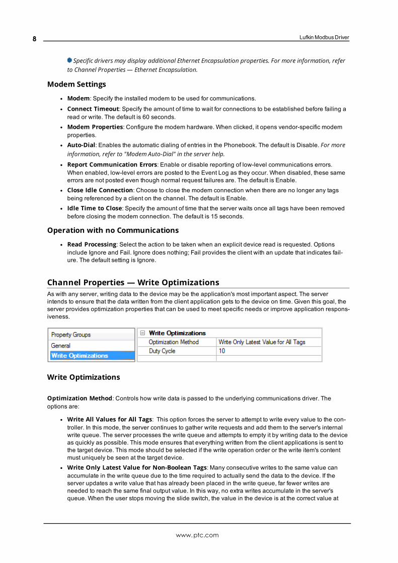
Write Optimizations
Optimization Method: Controls how write data is passed to the underlying communications driver. Theoptions are:
l Write All Values for All Tags: This option forces the server to attempt to write every value to the con-troller. In this mode, the server continues to gather write requests and add them to the server's internalwrite queue. The server processes the write queue and attempts to empty it by writing data to the deviceas quickly as possible. This mode ensures that everything written from the client applications is sent tothe target device. This mode should be selected if the write operation order or the write item's contentmust uniquely be seen at the target device.
l Write Only Latest Value for Non-Boolean Tags: Many consecutive writes to the same value canaccumulate in the write queue due to the time required to actually send the data to the device. If theserver updates a write value that has already been placed in the write queue, far fewer writes areneeded to reach the same final output value. In this way, no extra writes accumulate in the server'squeue. When the user stops moving the slide switch, the value in the device is at the correct value at
www.ptc.com
8
Lufkin Modbus Driver
virtually the same time. As the mode states, any value that is not a Boolean value is updated in theserver's internal write queue and sent to the device at the next possible opportunity. This can greatlyimprove the application performance.Note: This option does not attempt to optimize writes to Boolean values. It allows users to optimize
the operation of HMI data without causing problems with Boolean operations, such as a momentarypush button.
l Write Only Latest Value for All Tags: This option takes the theory behind the second optimizationmode and applies it to all tags. It is especially useful if the application only needs to send the latestvalue to the device. This mode optimizes all writes by updating the tags currently in the write queuebefore they are sent. This is the default mode.
Duty Cycle: is used to control the ratio of write to read operations. The ratio is always based on one read forevery one to ten writes. The duty cycle is set to ten by default, meaning that ten writes occur for each read oper-ation. Although the application is performing a large number of continuous writes, it must be ensured that readdata is still given time to process. A setting of one results in one read operation for every write operation. If thereare no write operations to perform, reads are processed continuously. This allows optimization for applicationswith continuous writes versus a more balanced back and forth data flow.Note: It is recommended that the application be characterized for compatibility with the write optimization
enhancements before being used in a production environment.
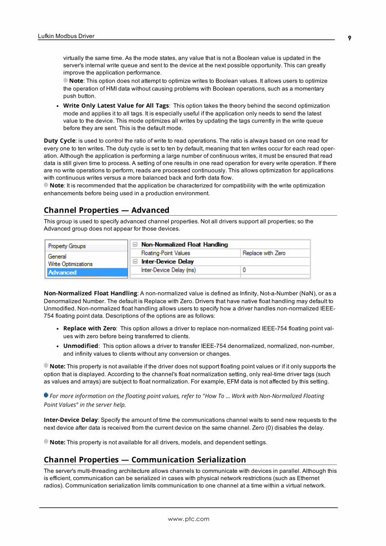
Channel Properties — AdvancedThis group is used to specify advanced channel properties. Not all drivers support all properties; so theAdvanced group does not appear for those devices.
Non-Normalized Float Handling: A non-normalized value is defined as Infinity, Not-a-Number (NaN), or as aDenormalized Number. The default is Replace with Zero. Drivers that have native float handling may default toUnmodified. Non-normalized float handling allows users to specify how a driver handles non-normalized IEEE-754 floating point data. Descriptions of the options are as follows:
l Replace with Zero: This option allows a driver to replace non-normalized IEEE-754 floating point val-ues with zero before being transferred to clients.
l Unmodified: This option allows a driver to transfer IEEE-754 denormalized, normalized, non-number,and infinity values to clients without any conversion or changes.
Note: This property is not available if the driver does not support floating point values or if it only supports theoption that is displayed. According to the channel's float normalization setting, only real-time driver tags (suchas values and arrays) are subject to float normalization. For example, EFM data is not affected by this setting.
For more information on the floating point values, refer to "How To ... Work with Non-Normalized FloatingPoint Values" in the server help.
Inter-Device Delay: Specify the amount of time the communications channel waits to send new requests to thenext device after data is received from the current device on the same channel. Zero (0) disables the delay.
Note: This property is not available for all drivers, models, and dependent settings.
Channel Properties — Communication SerializationThe server's multi-threading architecture allows channels to communicate with devices in parallel. Although thisis efficient, communication can be serialized in cases with physical network restrictions (such as Ethernetradios). Communication serialization limits communication to one channel at a time within a virtual network.
www.ptc.com
9
Lufkin ModbusDriver
The term "virtual network" describes a collection of channels and associated devices that use the same pipelinefor communications. For example, the pipeline of an Ethernet radio is the master radio. All channels using thesame master radio associate with the same virtual network. Channels are allowed to communicate each in turn,in a "round-robin" manner. By default, a channel can process one transaction before handing communicationsoff to another channel. A transaction can include one or more tags. If the controlling channel contains a devicethat is not responding to a request, the channel cannot release control until the transaction times out. This res-ults in data update delays for the other channels in the virtual network.
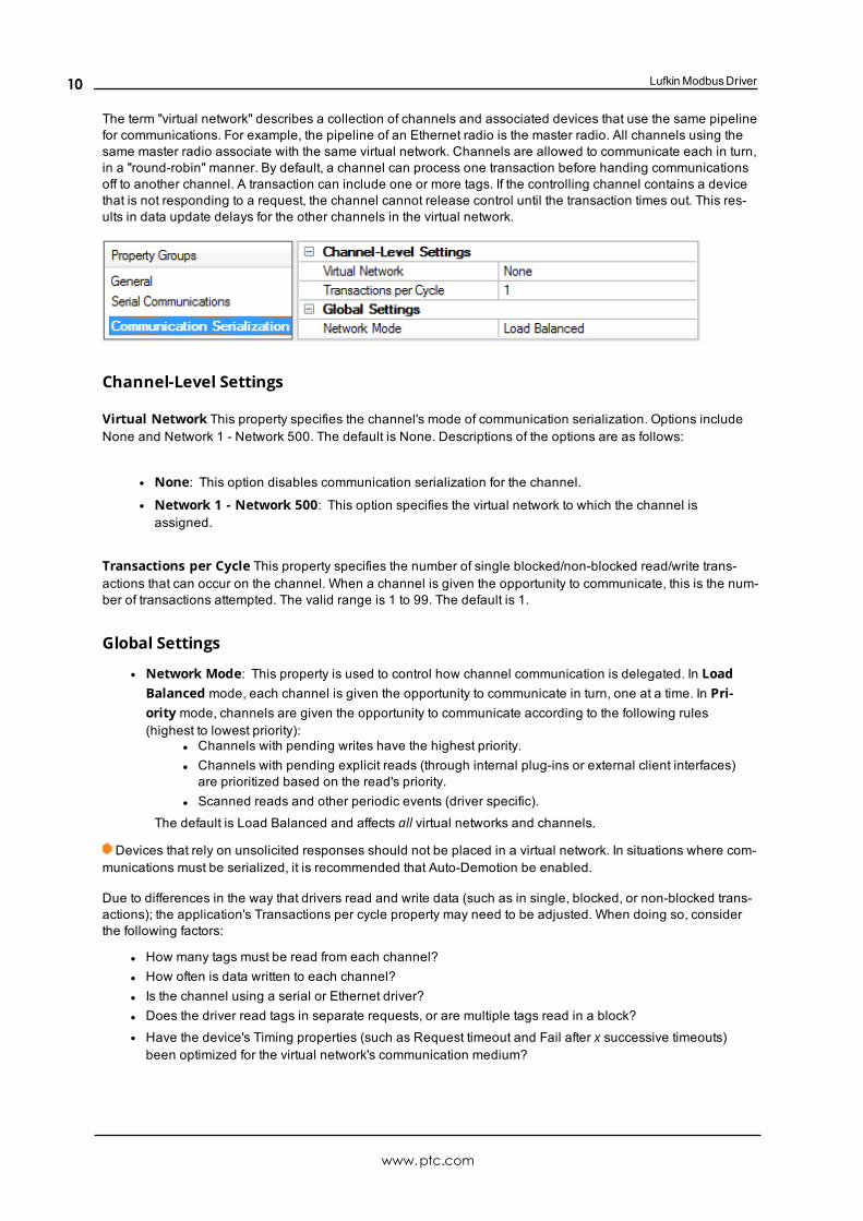
Channel-Level Settings
Virtual Network This property specifies the channel's mode of communication serialization. Options includeNone and Network 1 - Network 500. The default is None. Descriptions of the options are as follows:
l None: This option disables communication serialization for the channel.l Network 1 - Network 500: This option specifies the virtual network to which the channel isassigned.
Transactions per Cycle This property specifies the number of single blocked/non-blocked read/write trans-actions that can occur on the channel. When a channel is given the opportunity to communicate, this is the num-ber of transactions attempted. The valid range is 1 to 99. The default is 1.
Global Settings
l Network Mode: This property is used to control how channel communication is delegated. In LoadBalanced mode, each channel is given the opportunity to communicate in turn, one at a time. In Pri-ority mode, channels are given the opportunity to communicate according to the following rules(highest to lowest priority):
l Channels with pending writes have the highest priority.l Channels with pending explicit reads (through internal plug-ins or external client interfaces)are prioritized based on the read's priority.
l Scanned reads and other periodic events (driver specific).
The default is Load Balanced and affects all virtual networks and channels.
Devices that rely on unsolicited responses should not be placed in a virtual network. In situations where com-munications must be serialized, it is recommended that Auto-Demotion be enabled.
Due to differences in the way that drivers read and write data (such as in single, blocked, or non-blocked trans-actions); the application's Transactions per cycle property may need to be adjusted. When doing so, considerthe following factors:
l How many tags must be read from each channel?l How often is data written to each channel?l Is the channel using a serial or Ethernet driver?l Does the driver read tags in separate requests, or are multiple tags read in a block?l Have the device's Timing properties (such as Request timeout and Fail after x successive timeouts)been optimized for the virtual network's communication medium?
www.ptc.com
10
Lufkin Modbus Driver
Device SetupSupported DevicesInjection Well Controller (IWC)Progressive Cavity Pump (PCP)Rod Pump Controller (RPC)Variable Speed Drive (VSD)
MaximumNumber of DevicesThe maximum number of devices supported per channel is 2296.
IDs (PLC Network Address)Lufkin Modbus devices are assigned device IDs in the range 0 to 2295 (decimal). When using Modbus ID 0, thedriver will send only broadcast Write messages to remote stations. When configuring a device under the chan-nel, setting the ID to 0 will place that device in broadcast mode. Only Writes will occur from this device. Readsfrom the broadcast device will always return zero. All other IDs will read and write data to and from the remoteLufkin Modbus device.
ID FormatNumeric format used for the device ID. Available options are Octal, Decimal, and Hex. The default setting isDecimal.
Automatic Tag GenerationAutomatic Tag Generation is supported for the RPC and VSD device models. For more information on the CardTags that will be created, refer to Card Settings.
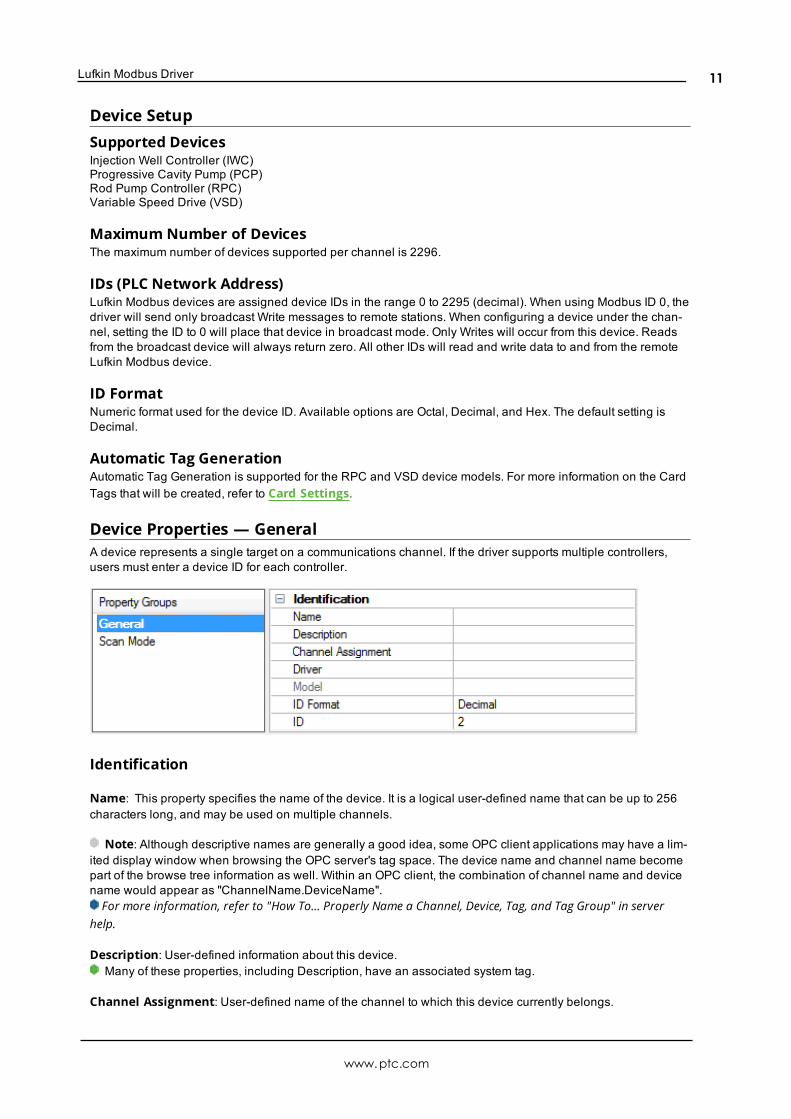
Device Properties — GeneralA device represents a single target on a communications channel. If the driver supports multiple controllers,users must enter a device ID for each controller.
Identification
Name: This property specifies the name of the device. It is a logical user-defined name that can be up to 256characters long, and may be used on multiple channels.
Note: Although descriptive names are generally a good idea, some OPC client applications may have a lim-ited display window when browsing the OPC server's tag space. The device name and channel name becomepart of the browse tree information as well. Within an OPC client, the combination of channel name and devicename would appear as "ChannelName.DeviceName".For more information, refer to "How To... Properly Name a Channel, Device, Tag, and Tag Group" in server
help.
Description: User-defined information about this device.Many of these properties, including Description, have an associated system tag.
Channel Assignment: User-defined name of the channel to which this device currently belongs.
www.ptc.com
11
Lufkin ModbusDriver
Driver: Selected protocol driver for this device.
Model: This property specifies the specific type of device that is associated with this ID. The contents of thedrop-down menu depends on the type of communications driver being used. Models that are not supported bya driver are disabled. If the communications driver supports multiple device models, the model selection canonly be changed when there are no client applications connected to the device.
Note: If the communication driver supports multiple models, users should try to match the model selection tothe physical device. If the device is not represented in the drop-down menu, select a model that conformsclosest to the target device. Some drivers support a model selection called "Open," which allows users to com-municate without knowing the specific details of the target device. For more information, refer to the driver helpdocumentation.
ID: This property specifies the device's driver-specific station or node. The type of ID entered depends on thecommunications driver being used. For many communication drivers, the ID is a numeric value. Drivers that sup-port a Numeric ID provide users with the option to enter a numeric value whose format can be changed to suitthe needs of the application or the characteristics of the selected communications driver. The format is set bythe driver by default. Options include Decimal, Octal, and Hexadecimal.
Note: If the driver is Ethernet-based or supports an unconventional station or node name, the device'sTCP/IP address may be used as the device ID. TCP/IP addresses consist of four values that are separated byperiods, with each value in the range of 0 to 255. Some device IDs are string based. There may be additionalproperties to configure within the ID field, depending on the driver. For more information, refer to the driver'shelp documentation.
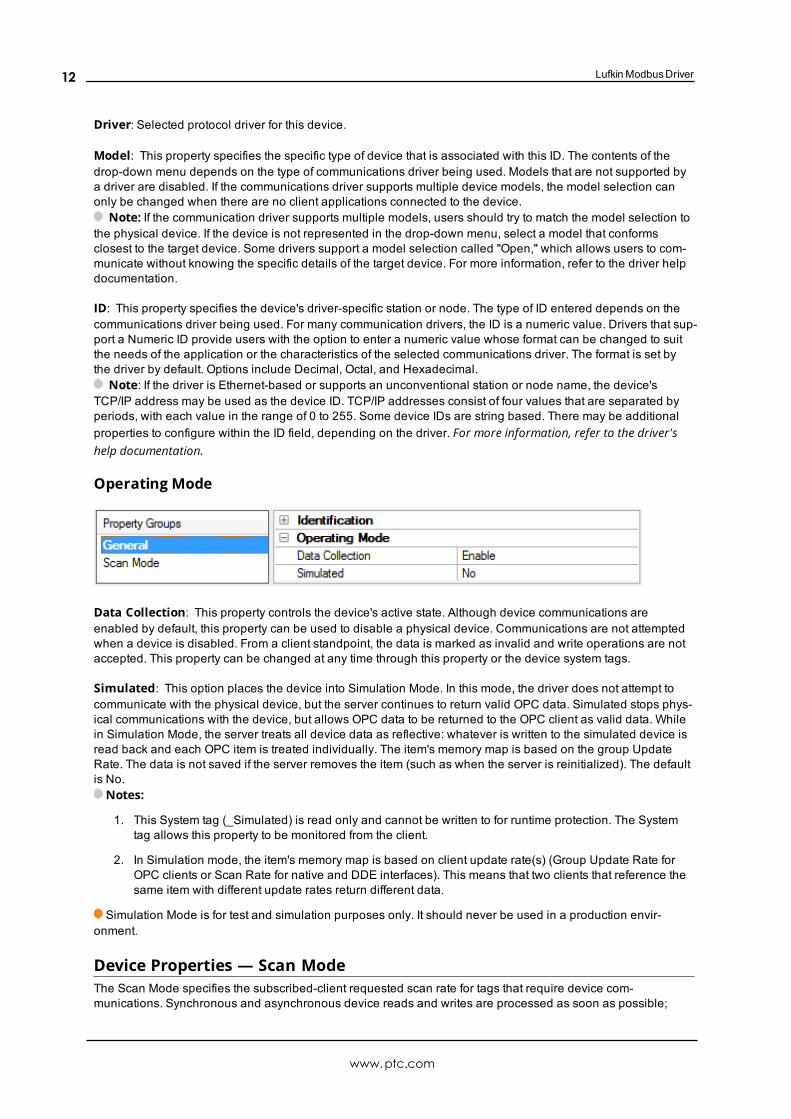
Operating Mode
Data Collection: This property controls the device's active state. Although device communications areenabled by default, this property can be used to disable a physical device. Communications are not attemptedwhen a device is disabled. From a client standpoint, the data is marked as invalid and write operations are notaccepted. This property can be changed at any time through this property or the device system tags.
Simulated: This option places the device into Simulation Mode. In this mode, the driver does not attempt tocommunicate with the physical device, but the server continues to return valid OPC data. Simulated stops phys-ical communications with the device, but allows OPC data to be returned to the OPC client as valid data. Whilein Simulation Mode, the server treats all device data as reflective: whatever is written to the simulated device isread back and each OPC item is treated individually. The item's memory map is based on the group UpdateRate. The data is not saved if the server removes the item (such as when the server is reinitialized). The defaultis No.Notes:
1. This System tag (_Simulated) is read only and cannot be written to for runtime protection. The Systemtag allows this property to be monitored from the client.
2. In Simulation mode, the item's memory map is based on client update rate(s) (Group Update Rate forOPC clients or Scan Rate for native and DDE interfaces). This means that two clients that reference thesame item with different update rates return different data.
Simulation Mode is for test and simulation purposes only. It should never be used in a production envir-onment.
Device Properties — Scan ModeThe Scan Mode specifies the subscribed-client requested scan rate for tags that require device com-munications. Synchronous and asynchronous device reads and writes are processed as soon as possible;
www.ptc.com
12
Lufkin Modbus Driver
unaffected by the Scan Mode properties.
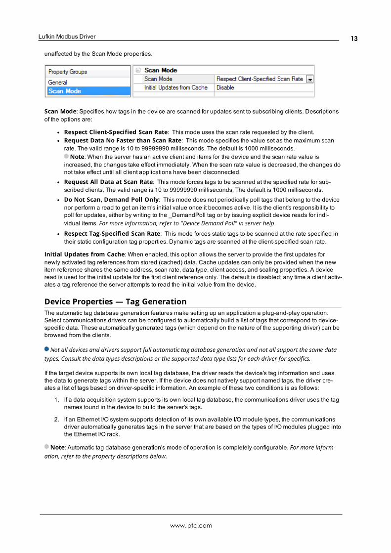
Scan Mode: Specifies how tags in the device are scanned for updates sent to subscribing clients. Descriptionsof the options are:
l Respect Client-Specified Scan Rate: This mode uses the scan rate requested by the client.l Request Data No Faster than Scan Rate: This mode specifies the value set as the maximum scanrate. The valid range is 10 to 99999990 milliseconds. The default is 1000 milliseconds.Note: When the server has an active client and items for the device and the scan rate value is
increased, the changes take effect immediately. When the scan rate value is decreased, the changes donot take effect until all client applications have been disconnected.
l Request All Data at Scan Rate: This mode forces tags to be scanned at the specified rate for sub-scribed clients. The valid range is 10 to 99999990 milliseconds. The default is 1000 milliseconds.
l Do Not Scan, Demand Poll Only: This mode does not periodically poll tags that belong to the devicenor perform a read to get an item's initial value once it becomes active. It is the client's responsibility topoll for updates, either by writing to the _DemandPoll tag or by issuing explicit device reads for indi-vidual items. For more information, refer to "Device Demand Poll" in server help.
l Respect Tag-Specified Scan Rate: This mode forces static tags to be scanned at the rate specified intheir static configuration tag properties. Dynamic tags are scanned at the client-specified scan rate.
Initial Updates from Cache: When enabled, this option allows the server to provide the first updates fornewly activated tag references from stored (cached) data. Cache updates can only be provided when the newitem reference shares the same address, scan rate, data type, client access, and scaling properties. A deviceread is used for the initial update for the first client reference only. The default is disabled; any time a client activ-ates a tag reference the server attempts to read the initial value from the device.
Device Properties — Tag GenerationThe automatic tag database generation features make setting up an application a plug-and-play operation.Select communications drivers can be configured to automatically build a list of tags that correspond to device-specific data. These automatically generated tags (which depend on the nature of the supporting driver) can bebrowsed from the clients.
Not all devices and drivers support full automatic tag database generation and not all support the same datatypes. Consult the data types descriptions or the supported data type lists for each driver for specifics.
If the target device supports its own local tag database, the driver reads the device's tag information and usesthe data to generate tags within the server. If the device does not natively support named tags, the driver cre-ates a list of tags based on driver-specific information. An example of these two conditions is as follows:
1. If a data acquisition system supports its own local tag database, the communications driver uses the tagnames found in the device to build the server's tags.
2. If an Ethernet I/O system supports detection of its own available I/O module types, the communicationsdriver automatically generates tags in the server that are based on the types of I/O modules plugged intothe Ethernet I/O rack.
Note: Automatic tag database generation's mode of operation is completely configurable. For more inform-ation, refer to the property descriptions below.
www.ptc.com
13
Lufkin ModbusDriver
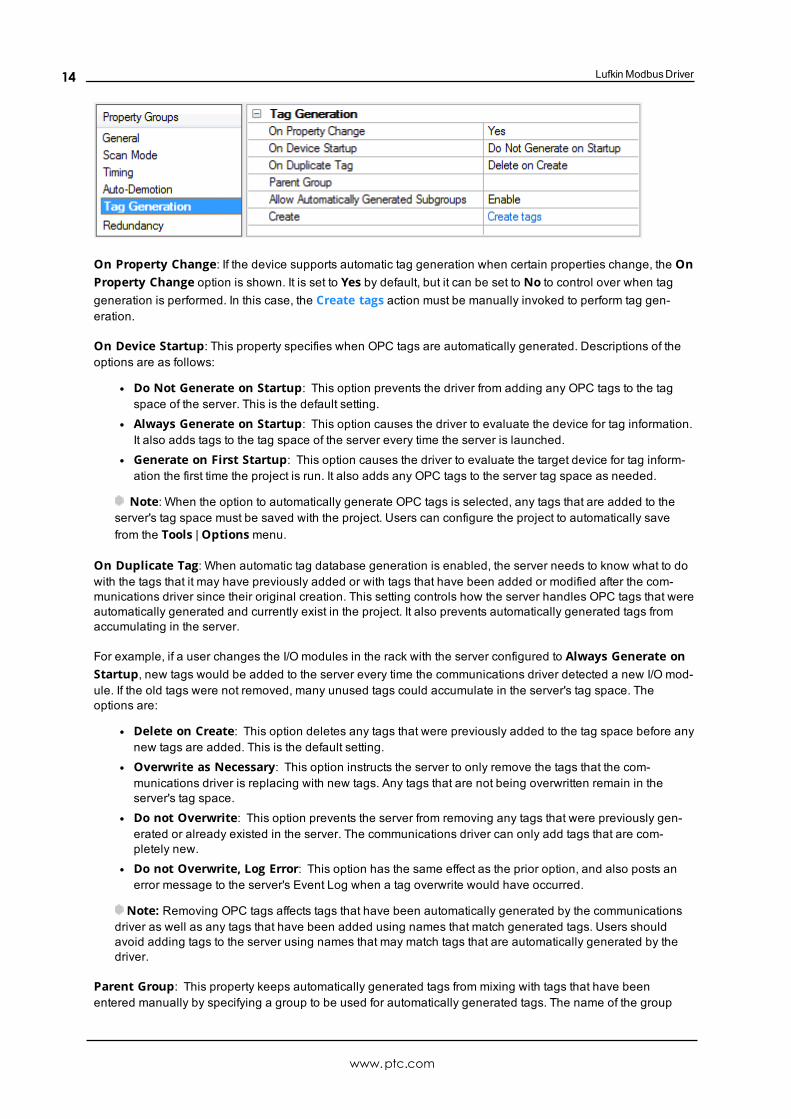
On Property Change: If the device supports automatic tag generation when certain properties change, the OnProperty Change option is shown. It is set to Yes by default, but it can be set to No to control over when taggeneration is performed. In this case, the Create tags action must be manually invoked to perform tag gen-eration.
On Device Startup: This property specifies when OPC tags are automatically generated. Descriptions of theoptions are as follows:
l Do Not Generate on Startup: This option prevents the driver from adding any OPC tags to the tagspace of the server. This is the default setting.
l Always Generate on Startup: This option causes the driver to evaluate the device for tag information.It also adds tags to the tag space of the server every time the server is launched.
l Generate on First Startup: This option causes the driver to evaluate the target device for tag inform-ation the first time the project is run. It also adds any OPC tags to the server tag space as needed.
Note: When the option to automatically generate OPC tags is selected, any tags that are added to theserver's tag space must be saved with the project. Users can configure the project to automatically savefrom the Tools | Options menu.
On Duplicate Tag: When automatic tag database generation is enabled, the server needs to know what to dowith the tags that it may have previously added or with tags that have been added or modified after the com-munications driver since their original creation. This setting controls how the server handles OPC tags that wereautomatically generated and currently exist in the project. It also prevents automatically generated tags fromaccumulating in the server.
For example, if a user changes the I/O modules in the rack with the server configured to Always Generate onStartup, new tags would be added to the server every time the communications driver detected a new I/O mod-ule. If the old tags were not removed, many unused tags could accumulate in the server's tag space. Theoptions are:
l Delete on Create: This option deletes any tags that were previously added to the tag space before anynew tags are added. This is the default setting.
l Overwrite as Necessary: This option instructs the server to only remove the tags that the com-munications driver is replacing with new tags. Any tags that are not being overwritten remain in theserver's tag space.
l Do not Overwrite: This option prevents the server from removing any tags that were previously gen-erated or already existed in the server. The communications driver can only add tags that are com-pletely new.
l Do not Overwrite, Log Error: This option has the same effect as the prior option, and also posts anerror message to the server's Event Log when a tag overwrite would have occurred.
Note: Removing OPC tags affects tags that have been automatically generated by the communicationsdriver as well as any tags that have been added using names that match generated tags. Users shouldavoid adding tags to the server using names that may match tags that are automatically generated by thedriver.
Parent Group: This property keeps automatically generated tags from mixing with tags that have beenentered manually by specifying a group to be used for automatically generated tags. The name of the group
www.ptc.com
14
Lufkin Modbus Driver
can be up to 256 characters. This parent group provides a root branch to which all automatically generated tagsare added.
Allow Automatically Generated Subgroups: This property controls whether the server automatically cre-ates subgroups for the automatically generated tags. This is the default setting. If disabled, the server generatesthe device's tags in a flat list without any grouping. In the server project, the resulting tags are named with theaddress value. For example, the tag names are not retained during the generation process.
Note: If, as the server is generating tags, a tag is assigned the same name as an existing tag, the systemautomatically increments to the next highest number so that the tag name is not duplicated. For example, if thegeneration process creates a tag named "AI22" that already exists, it creates the tag as "AI23" instead.
Create: Initiates the creation of automatically generated OPC tags. If the device's configuration has been mod-ified, Create tags forces the driver to reevaluate the device for possible tag changes. Its ability to be accessedfrom the System tags allows a client application to initiate tag database creation.
Note: Create tags is disabled if the Configuration edits a project offline.
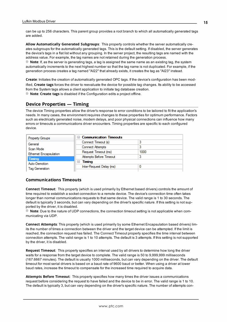
Device Properties — TimingThe device Timing properties allow the driver's response to error conditions to be tailored to fit the application'sneeds. In many cases, the environment requires changes to these properties for optimum performance. Factorssuch as electrically generated noise, modem delays, and poor physical connections can influence how manyerrors or timeouts a communications driver encounters. Timing properties are specific to each configureddevice.
Communications Timeouts
Connect Timeout: This property (which is used primarily by Ethernet based drivers) controls the amount oftime required to establish a socket connection to a remote device. The device's connection time often takeslonger than normal communications requests to that same device. The valid range is 1 to 30 seconds. Thedefault is typically 3 seconds, but can vary depending on the driver's specific nature. If this setting is not sup-ported by the driver, it is disabled.
Note: Due to the nature of UDP connections, the connection timeout setting is not applicable when com-municating via UDP.
Connect Attempts: This property (which is used primarily by some Ethernet Encapsulation based drivers) lim-its the number of times a connection between the driver and the target device can be attempted. If the limit isreached, the connection request has failed. The Connect Timeout property specifies the time interval betweenconnection attempts. The valid range is 1 to 10 attempts. The default is 3 attempts. If this setting is not supportedby the driver, it is disabled.
Request Timeout: This property specifies an interval used by all drivers to determine how long the driverwaits for a response from the target device to complete. The valid range is 50 to 9,999,999 milliseconds(167.6667 minutes). The default is usually 1000 milliseconds, but can vary depending on the driver. The defaulttimeout for most serial drivers is based on a baud rate of 9600 baud or better. When using a driver at lowerbaud rates, increase the timeout to compensate for the increased time required to acquire data.
Attempts Before Timeout: This property specifies how many times the driver issues a communicationsrequest before considering the request to have failed and the device to be in error. The valid range is 1 to 10.The default is typically 3, but can vary depending on the driver's specific nature. The number of attempts con-
www.ptc.com
15
Lufkin ModbusDriver
figured for an application depends largely on the communications environment. This property applies to bothconnection attempts and request attempts.
Timing
Inter-Request Delay: This property specifies how long the driver waits before sending the next request to thetarget device. It overrides the normal polling frequency of tags associated with the device, as well as one-timereads and writes. This delay can be useful when dealing with devices with slow turnaround times and in caseswhere network load is a concern. Configuring a delay for a device affects communications with all other deviceson the channel. It is recommended that users separate any device that requires an inter-request delay to a sep-arate channel if possible. Other communications properties (such as communication serialization) can extendthis delay. The valid range is 0 to 300,000 milliseconds; however, some drivers may limit the maximum valuedue to a function of their particular design. The default is 0, which indicates no delay between requests with thetarget device.
Note: Not all drivers support Inter-Request Delay. This setting does not appear if it is not available.
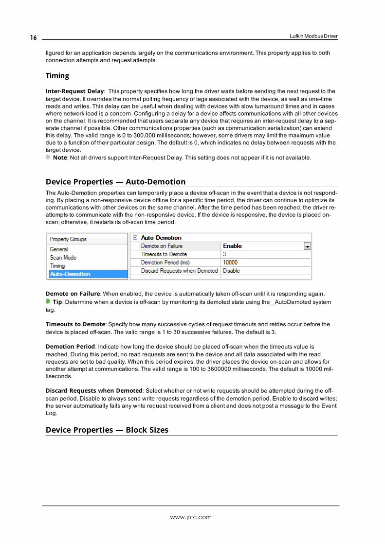
Device Properties — Auto-DemotionThe Auto-Demotion properties can temporarily place a device off-scan in the event that a device is not respond-ing. By placing a non-responsive device offline for a specific time period, the driver can continue to optimize itscommunications with other devices on the same channel. After the time period has been reached, the driver re-attempts to communicate with the non-responsive device. If the device is responsive, the device is placed on-scan; otherwise, it restarts its off-scan time period.
Demote on Failure: When enabled, the device is automatically taken off-scan until it is responding again.Tip: Determine when a device is off-scan by monitoring its demoted state using the _AutoDemoted system
tag.
Timeouts to Demote: Specify how many successive cycles of request timeouts and retries occur before thedevice is placed off-scan. The valid range is 1 to 30 successive failures. The default is 3.
Demotion Period: Indicate how long the device should be placed off-scan when the timeouts value isreached. During this period, no read requests are sent to the device and all data associated with the readrequests are set to bad quality. When this period expires, the driver places the device on-scan and allows foranother attempt at communications. The valid range is 100 to 3600000 milliseconds. The default is 10000 mil-liseconds.
Discard Requests when Demoted: Select whether or not write requests should be attempted during the off-scan period. Disable to always send write requests regardless of the demotion period. Enable to discard writes;the server automatically fails any write request received from a client and does not post a message to the EventLog.
Device Properties — Block Sizes
www.ptc.com
16
Lufkin Modbus Driver
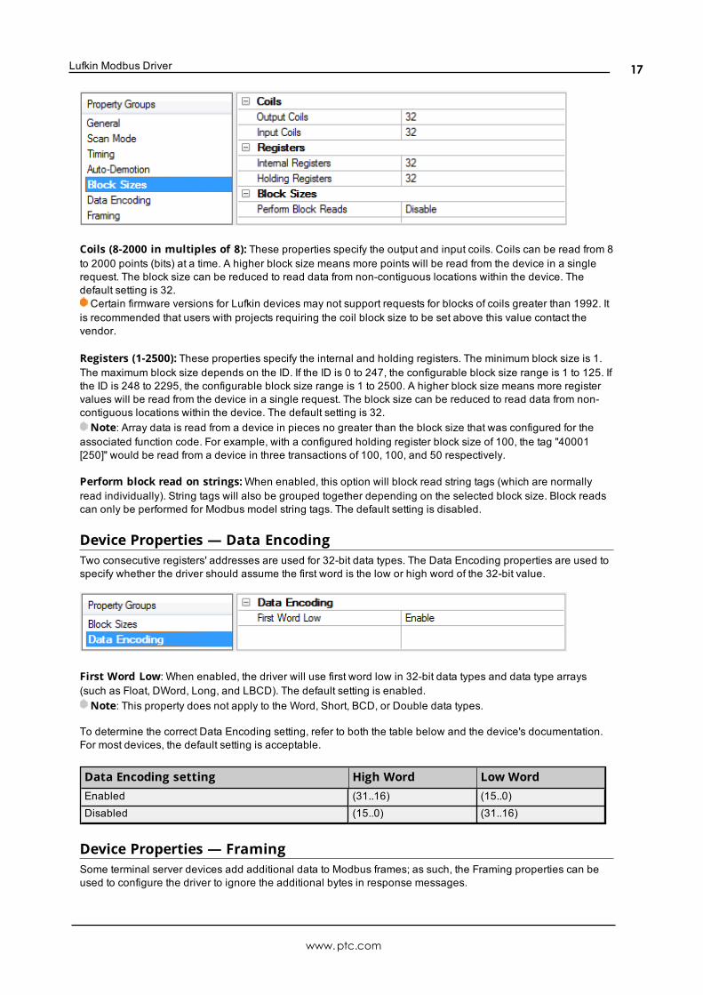
Coils (8-2000 in multiples of 8): These properties specify the output and input coils. Coils can be read from 8to 2000 points (bits) at a time. A higher block size means more points will be read from the device in a singlerequest. The block size can be reduced to read data from non-contiguous locations within the device. Thedefault setting is 32.Certain firmware versions for Lufkin devices may not support requests for blocks of coils greater than 1992. It
is recommended that users with projects requiring the coil block size to be set above this value contact thevendor.
Registers (1-2500): These properties specify the internal and holding registers. The minimum block size is 1.The maximum block size depends on the ID. If the ID is 0 to 247, the configurable block size range is 1 to 125. Ifthe ID is 248 to 2295, the configurable block size range is 1 to 2500. A higher block size means more registervalues will be read from the device in a single request. The block size can be reduced to read data from non-contiguous locations within the device. The default setting is 32.Note: Array data is read from a device in pieces no greater than the block size that was configured for the
associated function code. For example, with a configured holding register block size of 100, the tag "40001[250]" would be read from a device in three transactions of 100, 100, and 50 respectively.
Perform block read on strings:When enabled, this option will block read string tags (which are normallyread individually). String tags will also be grouped together depending on the selected block size. Block readscan only be performed for Modbus model string tags. The default setting is disabled.
Device Properties — Data EncodingTwo consecutive registers' addresses are used for 32-bit data types. The Data Encoding properties are used tospecify whether the driver should assume the first word is the low or high word of the 32-bit value.
First Word Low: When enabled, the driver will use first word low in 32-bit data types and data type arrays(such as Float, DWord, Long, and LBCD). The default setting is enabled. Note: This property does not apply to the Word, Short, BCD, or Double data types.
To determine the correct Data Encoding setting, refer to both the table below and the device's documentation.For most devices, the default setting is acceptable.
Data Encoding setting High Word Low WordEnabled (31..16) (15..0)Disabled (15..0) (31..16)
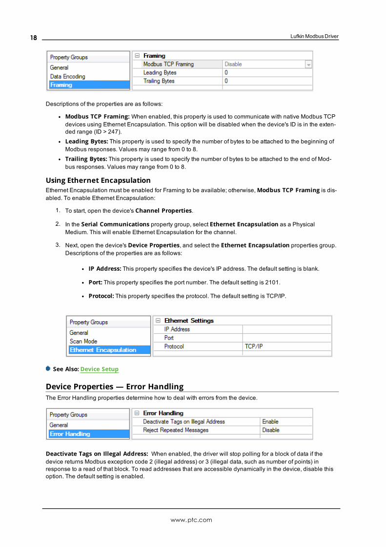
Device Properties — FramingSome terminal server devices add additional data to Modbus frames; as such, the Framing properties can beused to configure the driver to ignore the additional bytes in response messages.
www.ptc.com
17
Lufkin ModbusDriver
Descriptions of the properties are as follows:
l Modbus TCP Framing: When enabled, this property is used to communicate with native Modbus TCPdevices using Ethernet Encapsulation. This option will be disabled when the device's ID is in the exten-ded range (ID > 247).
l Leading Bytes: This property is used to specify the number of bytes to be attached to the beginning ofModbus responses. Values may range from 0 to 8.
l Trailing Bytes: This property is used to specify the number of bytes to be attached to the end of Mod-bus responses. Values may range from 0 to 8.
Using Ethernet EncapsulationEthernet Encapsulation must be enabled for Framing to be available; otherwise,Modbus TCP Framing is dis-abled. To enable Ethernet Encapsulation:
1. To start, open the device's Channel Properties.
2. In the Serial Communications property group, select Ethernet Encapsulation as a PhysicalMedium. This will enable Ethernet Encapsulation for the channel.
3. Next, open the device's Device Properties, and select the Ethernet Encapsulation properties group.Descriptions of the properties are as follows:
l IP Address: This property specifies the device's IP address. The default setting is blank.
l Port: This property specifies the port number. The default setting is 2101.
l Protocol: This property specifies the protocol. The default setting is TCP/IP.
See Also: Device Setup
Device Properties — Error HandlingThe Error Handling properties determine how to deal with errors from the device.
Deactivate Tags on Illegal Address: When enabled, the driver will stop polling for a block of data if thedevice returns Modbus exception code 2 (illegal address) or 3 (illegal data, such as number of points) inresponse to a read of that block. To read addresses that are accessible dynamically in the device, disable thisoption. The default setting is enabled.
www.ptc.com
18
Lufkin Modbus Driver
Reject Repeated Messages:When enabled, the driver will expect repeated messages. When disabled, thedriver will interpret a repeated message as an invalid response and will retry the request. The default setting isdisabled.
Note: Some message-relay equipment will echo Modbus requests back to the driver.
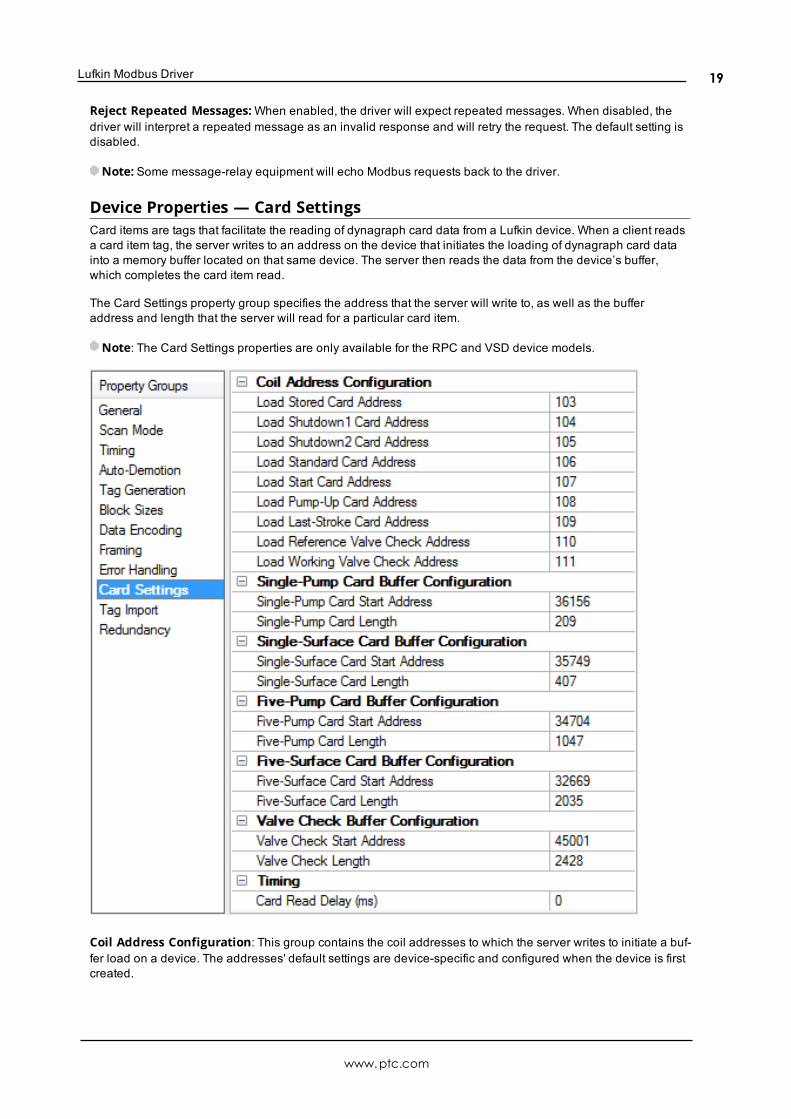
Device Properties — Card SettingsCard items are tags that facilitate the reading of dynagraph card data from a Lufkin device. When a client readsa card item tag, the server writes to an address on the device that initiates the loading of dynagraph card datainto a memory buffer located on that same device. The server then reads the data from the device’s buffer,which completes the card item read.
The Card Settings property group specifies the address that the server will write to, as well as the bufferaddress and length that the server will read for a particular card item.
Note: The Card Settings properties are only available for the RPC and VSD device models.
Coil Address Configuration: This group contains the coil addresses to which the server writes to initiate a buf-fer load on a device. The addresses' default settings are device-specific and configured when the device is firstcreated.
www.ptc.com
19
Lufkin ModbusDriver
Buffer Configuration: These five groups contain the memory buffers. Each memory buffer has a startingaddress and length property that the server uses when reading the dynagraph card data. The memory buffers'default starting addresses and lengths are device-specific and configured when the device is first created.
TimingCard Read Delay (ms): Specify the amount of time, in milliseconds, to pause for the device to load the correctdata into the buffer before reading it. For devices that are slow or have a lot of data to load, it is possible thatloading the data can take some time. Setting this to a non-zero value can allow a device to load the data beforeit is read.Note: During the delay, no other tags for that device are read. This can lead to failed reads (depending on cli-
ent and the device settings).
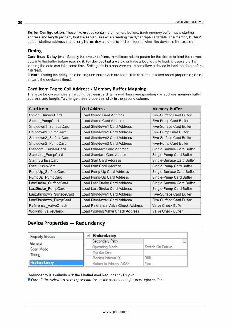
Card Item Tag to Coil Address / Memory Buffer MappingThe table below provides a mapping between card items and their corresponding coil address, memory bufferaddress, and length. To change these properties, click in the second column.
Card Item Coil Address Memory BufferStored_SurfaceCard Load Stored Card Address Five-Surface Card BufferStored_PumpCard Load Stored Card Address Five-Pump Card BufferShutdown1_SurfaceCard Load Shutdown1 Card Address Five-Surface Card BufferShutdown1_PumpCard Load Shutdown1 Card Address Five-Pump Card BufferShutdown2_SurfaceCard Load Shutdown2 Card Address Five-Surface Card BufferShutdown2_PumpCard Load Shutdown2 Card Address Five-Pump Card BufferStandard_SurfaceCard Load Standard Card Address Single-Surface Card BufferStandard_PumpCard Load Standard Card Address Single-Pump Card BufferStart_SurfaceCard Load Start Card Address Single-Surface Card BufferStart_PumpCard Load Start Card Address Single-Pump Card BufferPumpUp_SurfaceCard Load Pump-Up Card Address Single-Surface Card BufferPumpUp_PumpCard Load Pump-Up Card Address Single-Pump Card BufferLastStroke_SurfaceCard Load Last-Stroke Card Address Single-Surface Card BufferLastStroke_PumpCard Load Last-Stroke Card Address Single-Pump Card BufferLastShutdown_SurfaceCard Load Shutdown1 Card Address Five-Surface Card BufferLastShutdown_PumpCard Load Shutdown1 Card Address Five-Surface Card BufferReference_ValveCheck Load Reference Valve Check Address Valve Check BufferWorking_ValveCheck Load Working Valve Check Address Valve Check Buffer
Device Properties — Redundancy
Redundancy is available with the Media-Level Redundancy Plug-In.Consult the website, a sales representative, or the user manual for more information.
www.ptc.com
20
Lufkin Modbus Driver
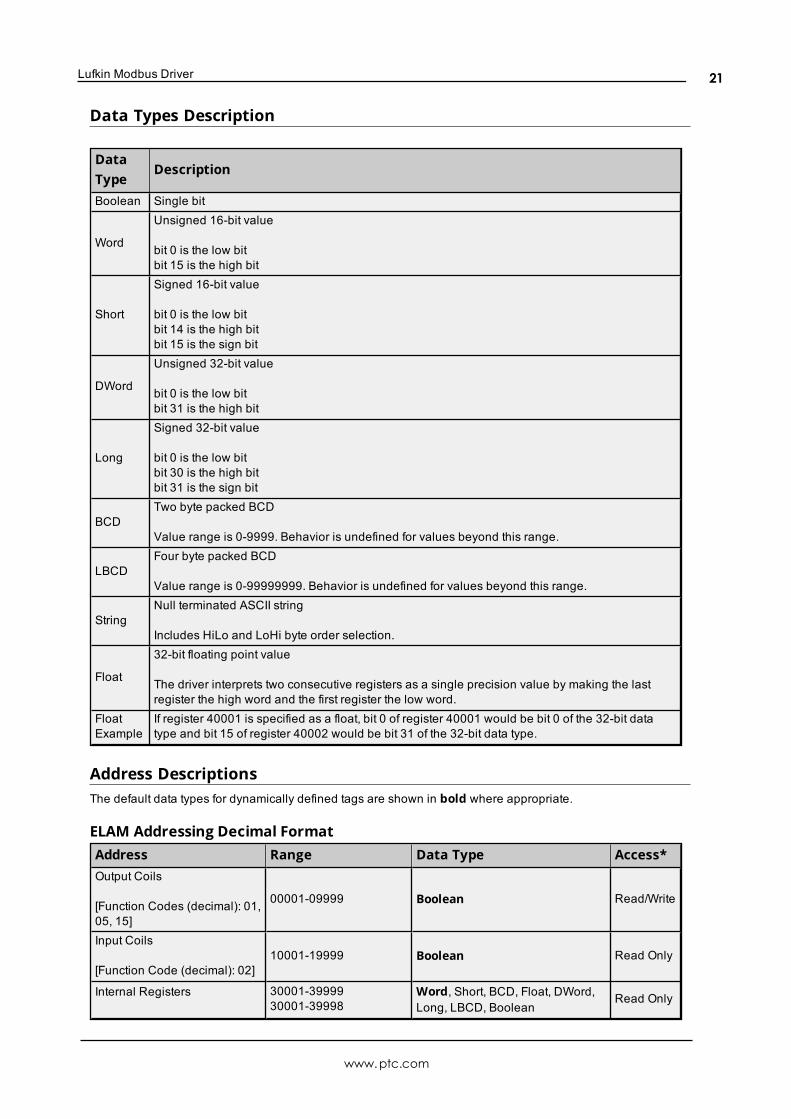
Data Types Description
DataType
Description
Boolean Single bit
Word
Unsigned 16-bit value
bit 0 is the low bitbit 15 is the high bit
Short
Signed 16-bit value
bit 0 is the low bitbit 14 is the high bitbit 15 is the sign bit
DWord
Unsigned 32-bit value
bit 0 is the low bitbit 31 is the high bit
Long
Signed 32-bit value
bit 0 is the low bitbit 30 is the high bitbit 31 is the sign bit
BCDTwo byte packed BCD
Value range is 0-9999. Behavior is undefined for values beyond this range.
LBCDFour byte packed BCD
Value range is 0-99999999. Behavior is undefined for values beyond this range.
StringNull terminated ASCII string
Includes HiLo and LoHi byte order selection.
Float
32-bit floating point value
The driver interprets two consecutive registers as a single precision value by making the lastregister the high word and the first register the low word.
FloatExample
If register 40001 is specified as a float, bit 0 of register 40001 would be bit 0 of the 32-bit datatype and bit 15 of register 40002 would be bit 31 of the 32-bit data type.
Address DescriptionsThe default data types for dynamically defined tags are shown in bold where appropriate.
ELAM Addressing Decimal FormatAddress Range Data Type Access*Output Coils
[Function Codes (decimal): 01,05, 15]
00001-09999 Boolean Read/Write
Input Coils
[Function Code (decimal): 02]10001-19999 Boolean Read Only
Internal Registers 30001-3999930001-39998
Word, Short, BCD, Float, DWord,Long, LBCD, Boolean
Read Only
www.ptc.com
21
Lufkin ModbusDriver
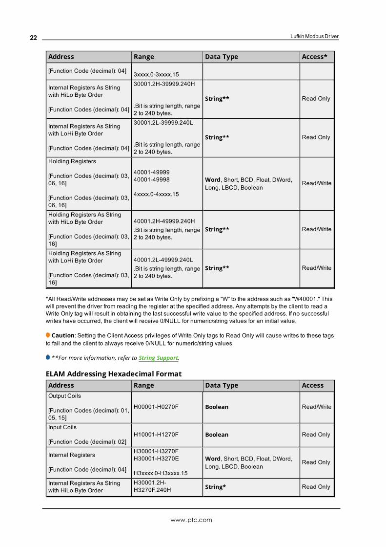
Address Range Data Type Access*
[Function Code (decimal): 04] 3xxxx.0-3xxxx.15
Internal Registers As Stringwith HiLo Byte Order
[Function Codes (decimal): 04]
30001.2H-39999.240H
.Bit is string length, range2 to 240 bytes.
String** Read Only
Internal Registers As Stringwith LoHi Byte Order
[Function Codes (decimal): 04]
30001.2L-39999.240L
.Bit is string length, range2 to 240 bytes.
String** Read Only
Holding Registers
[Function Codes (decimal): 03,06, 16]
[Function Codes (decimal): 03,06, 16]
40001-4999940001-49998
4xxxx.0-4xxxx.15
Word, Short, BCD, Float, DWord,Long, LBCD, Boolean
Read/Write
Holding Registers As Stringwith HiLo Byte Order
[Function Codes (decimal): 03,16]
40001.2H-49999.240H.Bit is string length, range2 to 240 bytes.
String** Read/Write
Holding Registers As Stringwith LoHi Byte Order
[Function Codes (decimal): 03,16]
40001.2L-49999.240L.Bit is string length, range2 to 240 bytes.
String** Read/Write
*All Read/Write addresses may be set as Write Only by prefixing a "W" to the address such as "W40001." Thiswill prevent the driver from reading the register at the specified address. Any attempts by the client to read aWrite Only tag will result in obtaining the last successful write value to the specified address. If no successfulwrites have occurred, the client will receive 0/NULL for numeric/string values for an initial value.
Caution: Setting the Client Access privileges of Write Only tags to Read Only will cause writes to these tagsto fail and the client to always receive 0/NULL for numeric/string values.
**For more information, refer to String Support.
ELAM Addressing Hexadecimal FormatAddress Range Data Type AccessOutput Coils
[Function Codes (decimal): 01,05, 15]
H00001-H0270F Boolean Read/Write
Input Coils
[Function Code (decimal): 02]H10001-H1270F Boolean Read Only
Internal Registers
[Function Code (decimal): 04]
H30001-H3270FH30001-H3270E
H3xxxx.0-H3xxxx.15
Word, Short, BCD, Float, DWord,Long, LBCD, Boolean
Read Only
Internal Registers As Stringwith HiLo Byte Order
H30001.2H-H3270F.240H String* Read Only
www.ptc.com
22
Lufkin Modbus Driver
Address Range Data Type Access
[Function Codes (decimal): 04] .Bit is string length, range2 to 240 bytes.
Internal Registers As Stringwith LoHi Byte Order
[Function Codes (decimal): 04]
H30001.2L-H3270F.240L
.Bit is string length, range2 to 240 bytes.
String* Read Only
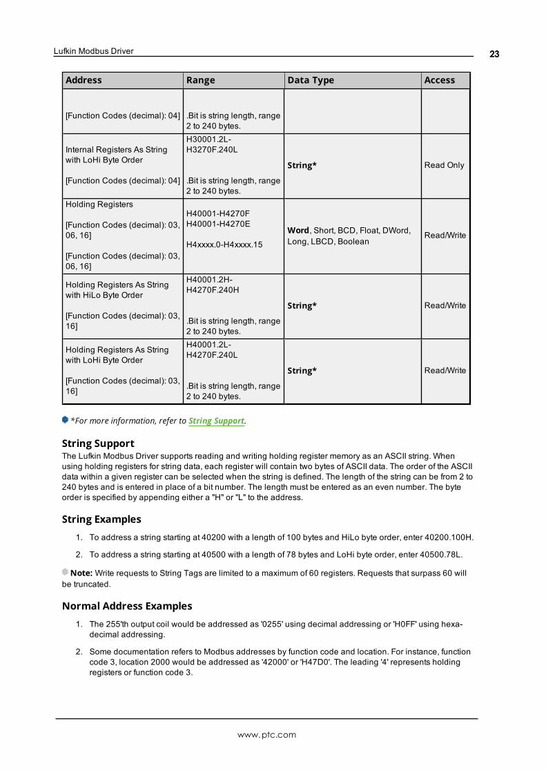
Holding Registers
[Function Codes (decimal): 03,06, 16]
[Function Codes (decimal): 03,06, 16]
H40001-H4270FH40001-H4270E
H4xxxx.0-H4xxxx.15
Word, Short, BCD, Float, DWord,Long, LBCD, Boolean
Read/Write
Holding Registers As Stringwith HiLo Byte Order
[Function Codes (decimal): 03,16]
H40001.2H-H4270F.240H
.Bit is string length, range2 to 240 bytes.
String* Read/Write
Holding Registers As Stringwith LoHi Byte Order
[Function Codes (decimal): 03,16]
H40001.2L-H4270F.240L
.Bit is string length, range2 to 240 bytes.
String* Read/Write
*For more information, refer to String Support.
String SupportThe Lufkin Modbus Driver supports reading and writing holding register memory as an ASCII string. Whenusing holding registers for string data, each register will contain two bytes of ASCII data. The order of the ASCIIdata within a given register can be selected when the string is defined. The length of the string can be from 2 to240 bytes and is entered in place of a bit number. The length must be entered as an even number. The byteorder is specified by appending either a "H" or "L" to the address.
String Examples
1. To address a string starting at 40200 with a length of 100 bytes and HiLo byte order, enter 40200.100H.
2. To address a string starting at 40500 with a length of 78 bytes and LoHi byte order, enter 40500.78L.
Note: Write requests to String Tags are limited to a maximum of 60 registers. Requests that surpass 60 willbe truncated.
Normal Address Examples
1. The 255'th output coil would be addressed as '0255' using decimal addressing or 'H0FF' using hexa-decimal addressing.
2. Some documentation refers to Modbus addresses by function code and location. For instance, functioncode 3, location 2000 would be addressed as '42000' or 'H47D0'. The leading '4' represents holdingregisters or function code 3.
www.ptc.com
23
Lufkin ModbusDriver
3. Some documentation refers to Modbus addresses by function code and location. For instance, settingfunction code 5, location 100 would be addressed as '0100' or 'H064'. The leading '0' represents outputcoils or function code 5. Writing 1 or 0 to this address would set or reset the coil.
Array SupportArrays are supported for internal and holding register locations for all data types except for Boolean and strings.Arrays are also supported for input and output coils (Boolean data types). There are two methods of addressingan array. Examples are given using holding register locations.
4xxxx [rows] [cols]4xxxx [cols] this method assumes rows is equal to one.
For arrays, rows multiplied by cols cannot exceed the maximum request size allowed by the protocol. Fordevices in standard Modbus mode, rows multiplied by cols multiplied by the data type length in registers cannotexceed 125. For devices in ELAM mode (ID > 247), rows multiplied by cols multiplied by the data type length inregisters cannot exceed 2500.
Note: Write requests to Array Tags are limited to a maximum of 60 registers. Requests that surpass 60 willresult in only the first 60 registers of the array being written to the device.
Packed Coil Address TypeThe Packed Coil address type allows access to multiple consecutive coils as an analog value. This feature isavailable for both input coils and output coils, polled mode only. The only valid data type is Word. The syntax isas follows:
Output coils: 0xxxx#nnWord Read/WriteInput coils: 1xxxx#nnWord Read Only
where xxxx is the address of the first coil (decimal and hex values allowed), and nn is the number of coils to bepacked into an analog value (1-16, decimal only).
The bit order will be such that the start address will be the least significant bit (LSB) of analog value.
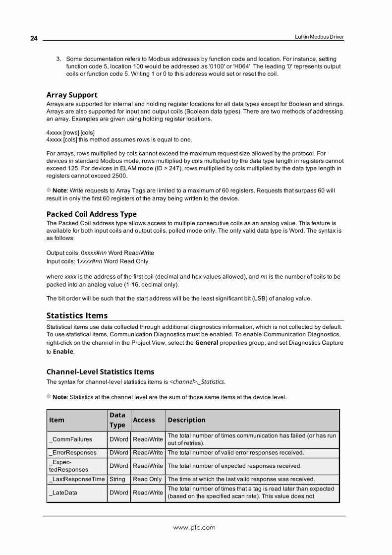
Statistics ItemsStatistical items use data collected through additional diagnostics information, which is not collected by default.To use statistical items, Communication Diagnostics must be enabled. To enable Communication Diagnostics,right-click on the channel in the Project View, select the General properties group, and set Diagnostics Captureto Enable.
Channel-Level Statistics ItemsThe syntax for channel-level statistics items is <channel>._Statistics.
Note: Statistics at the channel level are the sum of those same items at the device level.
ItemDataType
Access Description
_CommFailures DWord Read/Write The total number of times communication has failed (or has runout of retries).
_ErrorResponses DWord Read/Write The total number of valid error responses received._Expec-tedResponses DWord Read/Write The total number of expected responses received.
_LastResponseTime String Read Only The time at which the last valid response was received.
_LateData DWord Read/WriteThe total number of times that a tag is read later than expected(based on the specified scan rate). This value does not
www.ptc.com
24
Lufkin Modbus Driver
ItemDataType
Access Description
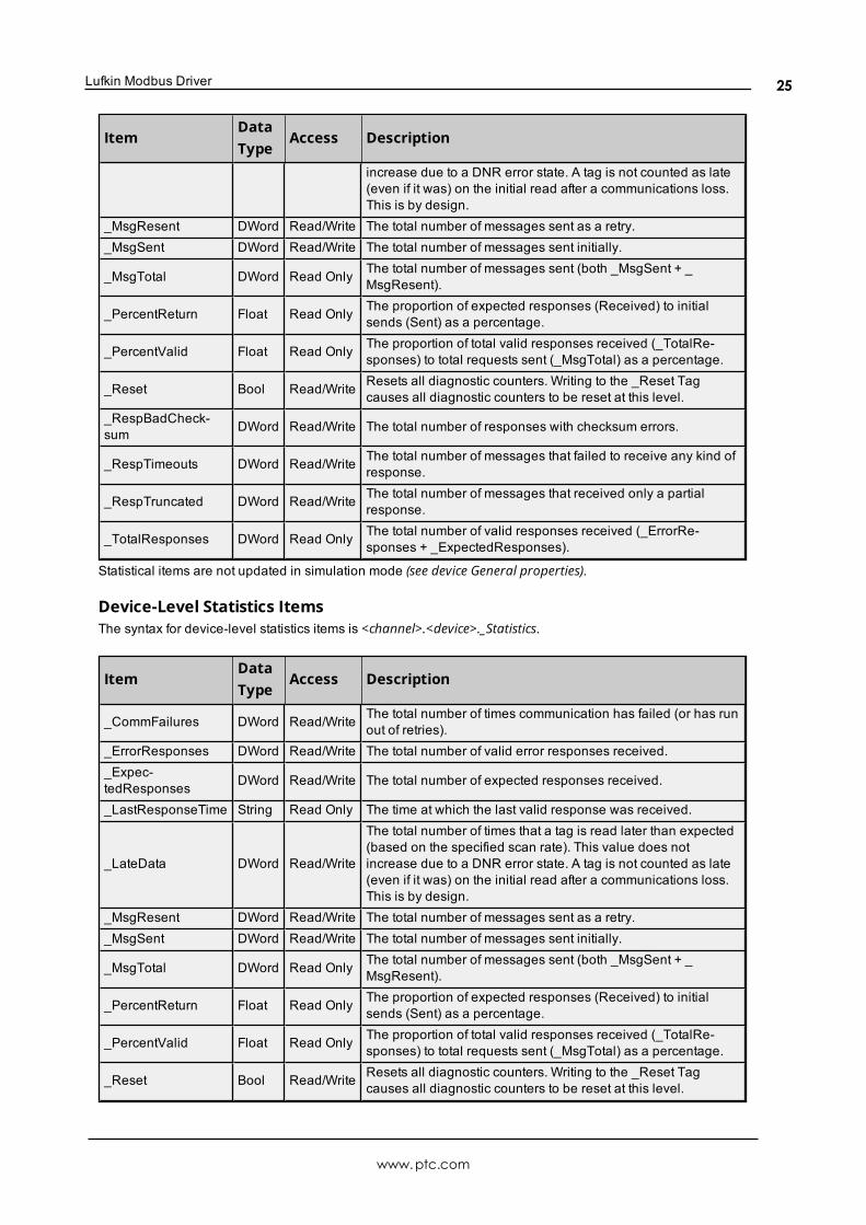
increase due to a DNR error state. A tag is not counted as late(even if it was) on the initial read after a communications loss.This is by design.
_MsgResent DWord Read/Write The total number of messages sent as a retry._MsgSent DWord Read/Write The total number of messages sent initially.
_MsgTotal DWord Read Only The total number of messages sent (both _MsgSent + _MsgResent).
_PercentReturn Float Read Only The proportion of expected responses (Received) to initialsends (Sent) as a percentage.
_PercentValid Float Read Only The proportion of total valid responses received (_TotalRe-sponses) to total requests sent (_MsgTotal) as a percentage.
_Reset Bool Read/Write Resets all diagnostic counters. Writing to the _Reset Tagcauses all diagnostic counters to be reset at this level.
_RespBadCheck-sum DWord Read/Write The total number of responses with checksum errors.
_RespTimeouts DWord Read/Write The total number of messages that failed to receive any kind ofresponse.
_RespTruncated DWord Read/Write The total number of messages that received only a partialresponse.
_TotalResponses DWord Read Only The total number of valid responses received (_ErrorRe-sponses + _ExpectedResponses).
Statistical items are not updated in simulation mode (see device General properties).
Device-Level Statistics ItemsThe syntax for device-level statistics items is <channel>.<device>._Statistics.
ItemDataType
Access Description
_CommFailures DWord Read/Write The total number of times communication has failed (or has runout of retries).
_ErrorResponses DWord Read/Write The total number of valid error responses received._Expec-tedResponses DWord Read/Write The total number of expected responses received.
_LastResponseTime String Read Only The time at which the last valid response was received.
_LateData DWord Read/Write
The total number of times that a tag is read later than expected(based on the specified scan rate). This value does notincrease due to a DNR error state. A tag is not counted as late(even if it was) on the initial read after a communications loss.This is by design.
_MsgResent DWord Read/Write The total number of messages sent as a retry._MsgSent DWord Read/Write The total number of messages sent initially.
_MsgTotal DWord Read Only The total number of messages sent (both _MsgSent + _MsgResent).
_PercentReturn Float Read Only The proportion of expected responses (Received) to initialsends (Sent) as a percentage.
_PercentValid Float Read Only The proportion of total valid responses received (_TotalRe-sponses) to total requests sent (_MsgTotal) as a percentage.
_Reset Bool Read/Write Resets all diagnostic counters. Writing to the _Reset Tagcauses all diagnostic counters to be reset at this level.
www.ptc.com
25
Lufkin ModbusDriver
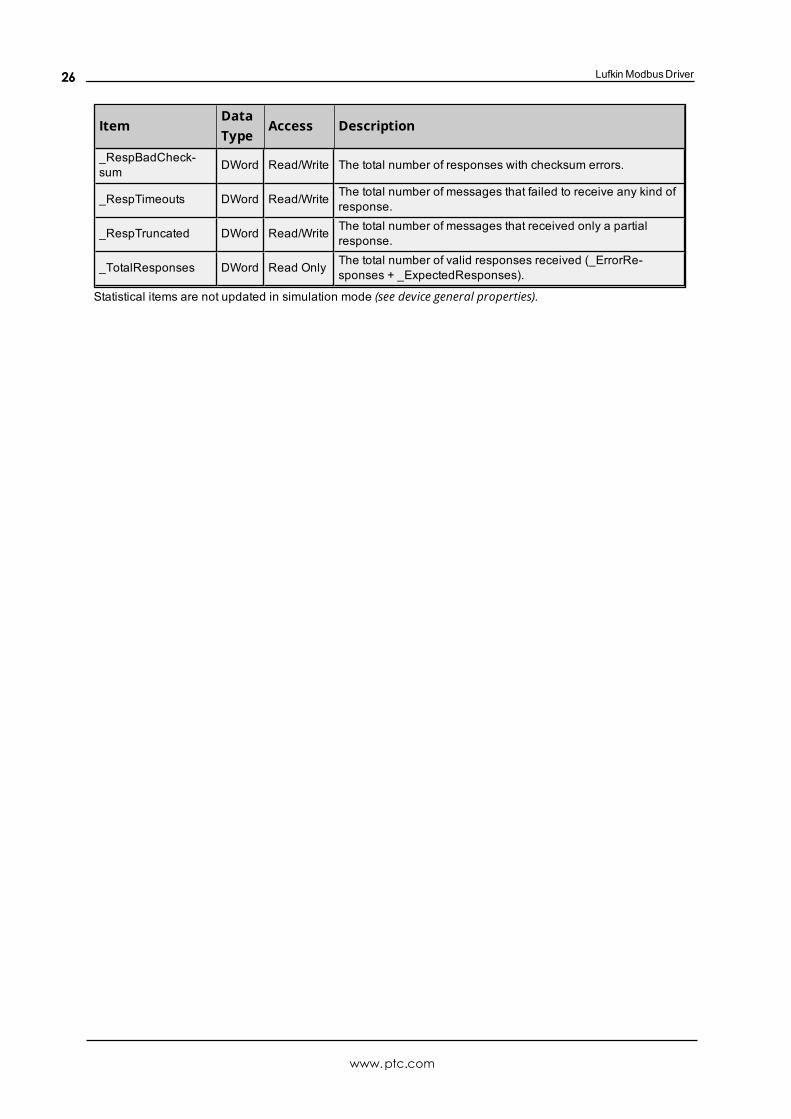
ItemDataType
Access Description
_RespBadCheck-sum DWord Read/Write The total number of responses with checksum errors.
_RespTimeouts DWord Read/Write The total number of messages that failed to receive any kind ofresponse.
_RespTruncated DWord Read/Write The total number of messages that received only a partialresponse.
_TotalResponses DWord Read Only The total number of valid responses received (_ErrorRe-sponses + _ExpectedResponses).
Statistical items are not updated in simulation mode (see device general properties).
www.ptc.com
26
Lufkin Modbus Driver
Error DescriptionsThe following categories of error/warning messages may be generated. Click on the link for list of messages.
Address ValidationDevice Status MessagesLufkin Modbus Specific MessagesSerial Communications
See Also:Modbus Exception Codes
Address ValidationThe following error/warning messages may be generated. Click on the link for a description of the message.
Address <address> is out of range for the specified device or register.Array size is out of range for address <address>.Array support is not available for the specified address: <address>.Data Type <type> is not valid for device address <address>.Device address <address> contains a syntax error.Device address <address> is not supported by model <model name>.Device address <address> is read only.Missing address.
Address <address> is out of range for the specified device or register.Error Type:Warning
Possible Cause:A tag address that has been specified statically references a location that is beyond the range of supported loc-ations for the device.
Solution:Verify that the address is correct; if it is not, re-enter it in the client application.
Array size is out of range for address <address>.Error Type:Warning
Possible Cause:A tag address that has been specified statically is requesting an array size that is too large for the driver'saddress type or block size.
Solution:Re-enter the address in the client application to specify a smaller value for the array or a different starting point.
Array support is not available for the specified address: <address>.Error Type:Warning
www.ptc.com
27
Lufkin ModbusDriver
Possible Cause:A tag address that has been specified statically contains an array reference for an address type that doesn't sup-port arrays.
Solution:Re-enter the address in the client application to remove the array reference or correct the address type.
Data Type <type> is not valid for device address <address>.Error Type:Warning
Possible Cause:A tag address that has been specified statically has been assigned an invalid data type.
Solution:Modify the requested data type in the client application.
Device address <address> contains a syntax error.Error Type:Warning
Possible Cause:A tag address that has been specified statically contains one or more invalid characters.
Solution:Re-enter the address in the client application.
Device address <address> is not supported by model <model name>.Error Type:Warning
Possible Cause:A tag address that has been specified statically references a location that is valid for the communications pro-tocol but not supported by the target device.
Solution:Verify that the address is correct; if it is not, re-enter it in the client application. Also verify that the selectedmodel name for the device is correct.
Device address <address> is read only.Error Type:Warning
Possible Cause:A tag address that has been specified statically has a requested access mode that is not compatible with whatthe device supports for that address.
Solution:Change the access mode in the client application.
www.ptc.com
28
Lufkin Modbus Driver
Missing addressError Type:Warning
Possible Cause:A tag address that has been specified statically has no length.
Solution:Re-enter the address in the client application.
Serial CommunicationsThe following error/warning messages may be generated. Click on the link for a description of the message.
COMn does not exist.COMn is in use by another application.Error opening COMn [OS Error == <OS Error ID>].Serial communications error on channel <channel name> [<error mask>].Unable to set comm parameters on COMn [OS Error == <OS Error ID>].
COMn does not exist.Error Type:Fatal
Possible Cause:The specified COM port is not present on the target computer.
Solution:Verify that the proper COM port has been selected.
COMn is in use by another application.Error Type:Fatal
Possible Cause:The serial port assigned to a device is being used by another application.
Solution:
1. Verify that the correct port has been assigned to the channel.
2. Verify that only one copy of the current project is running.
Error opening COMn [OS Error == <OS Error ID>].Error Type:Fatal
Possible Cause:The specified COM port could not be opened due to an internal hardware or software problem on the targetcomputer.
www.ptc.com
29
Lufkin ModbusDriver
Solution:Verify that the COM port is functional and may be accessed by other Windows applications.
Serial communications error on channel <channel name> [<error mask>].Error Type:Serious
Error Mask Definitions:B = Hardware break detected.F = Framing error.E = I/O error.O = Character buffer overrun.R = RX buffer overrun.P = Received byte parity error.T = TX buffer full.
Possible Cause:
1. The serial connection between the device and the Host PC is bad.
2. The communications properties for the serial connection are incorrect.
Solution:
1. Verify the cabling between the PC and the PLC device.
2. Verify that the specified communications properties match those of the device.
Unable to set comm parameters on COMn [OS Error == <OS Error ID>].Error Type:Fatal
Possible Cause:The serial properties for the specified COM port are not valid.
Solution:Verify the serial properties and make any necessary changes.
Device Status MessagesThe following error/warning messages may be generated. Click on the link for a description of the message.
Device <device name> is not responding.Unable to write to <address> on device <device name>.Unable to write to address <address> on device <device>: Device responded with excep-tion code <code>.Write failed for <tag name> on device <device name>. Maximum path length of <num-ber> characters exceeded.
Device <device name> is not responding.Error Type:Serious
www.ptc.com
30
Lufkin Modbus Driver
Possible Cause:
1. The serial connection between the device and the Host PC is broken.
2. The communications properties for the serial connection are incorrect.
3. The named device may have been assigned an incorrect Network ID.
4. The response from the device took longer to receive than the amount of time specified in the "RequestTimeout" device property.
Solution:
1. Verify the cabling between the PC and the PLC device.
2. Verify that the specified communications properties match those of the device.
3. Verify that the Network ID given to the named device matches that of the actual device.
4. Increase the Request Timeout property so that the entire response can be handled.
Unable to write to <address> on device <device name>.Error Type:Serious
Possible Cause:
1. The serial connection between the device and the host PC is broken.
2. The communications properties for the serial connection are incorrect.
3. The named device may have been assigned an incorrect network ID.
Solution:
1. Verify the cabling between the PC and the PLC device.
2. Verify that the specified communications properties match those of the device.
3. Verify that the Network ID given to the named device matches that of the actual device.
Unable to write to address <address> on device <device>: Device respon-ded with exception code <code>.Error Type:Warning
Possible Cause:SeeModbus Exception Codes for a description of the exception code.
Solution:SeeModbus Exception Codes.
Write failed for <tag name> on device <device name>. Maximum pathlength of <number> exceeded.Error Type:Warning
Possible Cause:
www.ptc.com
31
Lufkin ModbusDriver
Path length is limited to the indicated number of characters.
Solution:Devise a shorter path.
Lufkin Modbus Specific MessagesThe following error/warning messages may be generated. Click on the link for a description of the message.
Bad address in block [<start address> to <end address>] on device <device name>.Bad array spanning [<address> to <address>] on device <device>.
Bad address in block [<start address> to <end address>] on device <devicename>.Error Type:Serious
Possible Cause:
1. An attempt has been made to reference a nonexistent location in the specified device.
2. An attempt has been made to read more registers than allowed by the protocol.
Solution:
1. Verify the tags assigned to addresses in the specified range on the device and eliminate ones that ref-erence invalid locations.
2. Decrease the register block size value to 125.
See Also:Error HandlingBlock Sizes
Bad array spanning [<address> to <address>] on device <device>.Error Type:Serious
Possible Cause:
1. An attempt has been made to reference a nonexistent location in the specified device.
2. An attempt has been made to read more registers than allowed by the protocol.
Solution:
1. Verify that all the register addresses requested in the array exist in the device and reduce the array sizesuch that only valid addresses (that exist in the device) are requested by the array.
2. Reduce the array size value to 125.
See Also:Error HandlingBlock Sizes
www.ptc.com
32
Lufkin Modbus Driver
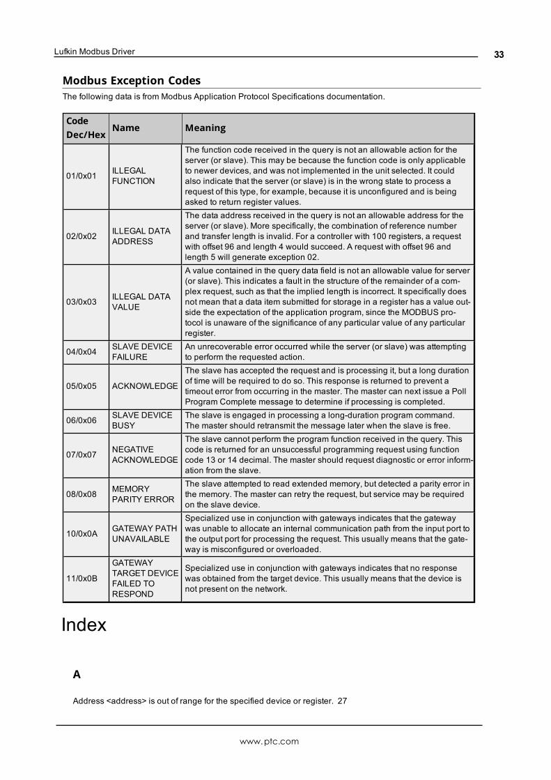
Modbus Exception CodesThe following data is from Modbus Application Protocol Specifications documentation.
CodeDec/Hex
Name Meaning
01/0x01 ILLEGALFUNCTION
The function code received in the query is not an allowable action for theserver (or slave). This may be because the function code is only applicableto newer devices, and was not implemented in the unit selected. It couldalso indicate that the server (or slave) is in the wrong state to process arequest of this type, for example, because it is unconfigured and is beingasked to return register values.
02/0x02 ILLEGAL DATAADDRESS
The data address received in the query is not an allowable address for theserver (or slave). More specifically, the combination of reference numberand transfer length is invalid. For a controller with 100 registers, a requestwith offset 96 and length 4 would succeed. A request with offset 96 andlength 5 will generate exception 02.
03/0x03 ILLEGAL DATAVALUE
A value contained in the query data field is not an allowable value for server(or slave). This indicates a fault in the structure of the remainder of a com-plex request, such as that the implied length is incorrect. It specifically doesnot mean that a data item submitted for storage in a register has a value out-side the expectation of the application program, since the MODBUS pro-tocol is unaware of the significance of any particular value of any particularregister.
04/0x04 SLAVE DEVICEFAILURE
An unrecoverable error occurred while the server (or slave) was attemptingto perform the requested action.
05/0x05 ACKNOWLEDGE
The slave has accepted the request and is processing it, but a long durationof time will be required to do so. This response is returned to prevent atimeout error from occurring in the master. The master can next issue a PollProgram Complete message to determine if processing is completed.
06/0x06 SLAVE DEVICEBUSY
The slave is engaged in processing a long-duration program command.The master should retransmit the message later when the slave is free.
07/0x07 NEGATIVEACKNOWLEDGE
The slave cannot perform the program function received in the query. Thiscode is returned for an unsuccessful programming request using functioncode 13 or 14 decimal. The master should request diagnostic or error inform-ation from the slave.
08/0x08 MEMORYPARITY ERROR
The slave attempted to read extended memory, but detected a parity error inthe memory. The master can retry the request, but service may be requiredon the slave device.
10/0x0A GATEWAY PATHUNAVAILABLE
Specialized use in conjunction with gateways indicates that the gatewaywas unable to allocate an internal communication path from the input port tothe output port for processing the request. This usually means that the gate-way is misconfigured or overloaded.
11/0x0B
GATEWAYTARGET DEVICEFAILED TORESPOND
Specialized use in conjunction with gateways indicates that no responsewas obtained from the target device. This usually means that the device isnot present on the network.
Index
A
Address <address> is out of range for the specified device or register. 27
www.ptc.com
33
Lufkin ModbusDriver
Address Descriptions 21
Address Validation 27
Allow Sub Groups 15
Array size is out of range for address <address>. 27
Array support is not available for the specified address: <address>. 27
Attempts Before Timeout 15
Auto-Demotion 16
B
Bad address in block [<start address> to <end address>] on device <device name>. 32
Bad array spanning [<address> to <address>] on device <device>. 32
BCD 21
Block Size 11
Block Sizes 16
Boolean 21
C
Card Settings 19
Channel Assignment 11
Channel Setup 4
Channels, maximum 11
Communications Timeouts 15-16
COMn does not exist. 29
COMn is in use by another application. 29
Connect Attempts 15
Connect Timeout 15
Create 15
D
Data Collection 12
Data Encoding 17
Data Type <type> is not valid for device address <address>. 28
Data Types Description 21
Delete 14
Demote on Failure 16
Demotion Period 16
Device <device name> is not responding. 30
Device address <address> contains a syntax error. 28
Device address <address> is not supported by model <model name>. 28
Device address <address> is read only. 28
www.ptc.com
34
Lufkin Modbus Driver
Device ID 11
Device Properties — Tag Generation 13
Device Status Messages 30
Devices, maximum 11
Discard Requests when Demoted 16
Do Not Scan, Demand Poll Only 13
Driver 12
DWord 21
E
Error Descriptions 27
Error Handling 18
Error opening COMn [OS Error == <OS Error ID>]. 29
F
Framing 17, 30
G
General 11
Generate 14
I
ID 12
Identification 11
Initial Updates from Cache 13
Inter-Request Delay 16
L
LBCD 21
Long 21
Lufkin Modbus Specific Messages 32
M
Missing address 29
Modbus Exception Codes 33
www.ptc.com
35
Lufkin ModbusDriver
Model 12
N
Name 11
Network 5
O
On Device Startup 14
On Duplicate Tag 14
On Property Change 14
Operating Mode 12
Overrun 30
Overview 4
Overwrite 14
P
Parent Group 15
Parity 30
R
Redundancy 20
Request Timeout 15
Respect Tag-Specified Scan Rate 13
S
Scan Mode 13
Serial Communications 29
Serial communications error on channel <channel name> [<error mask>]. 30
Short 21
Simulated 12
Statistics Items 24
T
Tag Generation 13
Timeouts to Demote 16
www.ptc.com
36
Lufkin Modbus Driver
U
Unable to set comm parameters on COMn [OS Error == <OS Error ID>]. 30
Unable to write to <address> on device <device name>. 31
Unable to write to address <address> on device <device>: Device responded with exception code<code>. 31
W
Word 21
Write failed for <tag name> on device <device name>. Maximum path length of <number> exceeded. 31
www.ptc.com
37