Embed Size (px)
Citation preview

Siemens S7-200 Driver
© 2018 PTC Inc. All Rights Reserved.
Siemens S7-200 Driver
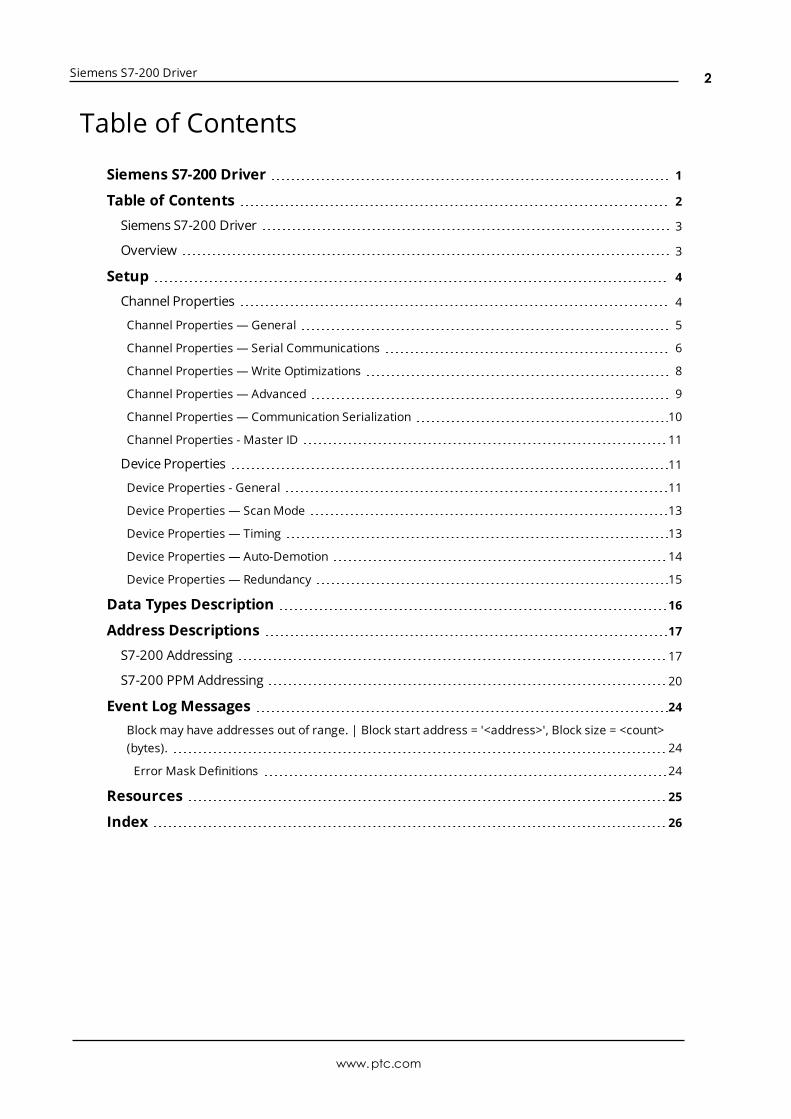
Table of Contents
Siemens S7-200 Driver 1
Table of Contents 2
Siemens S7-200 Driver 3
Overview 3
Setup 4
Channel Properties 4
Channel Properties — General 5
Channel Properties — Serial Communications 6
Channel Properties — Write Optimizations 8
Channel Properties — Advanced 9
Channel Properties — Communication Serialization 10
Channel Properties - Master ID 11
Device Properties 11
Device Properties - General 11
Device Properties — ScanMode 13
Device Properties — Timing 13
Device Properties — Auto-Demotion 14
Device Properties — Redundancy 15
Data Types Description 16
Address Descriptions 17
S7-200 Addressing 17
S7-200 PPM Addressing 20
Event Log Messages 24
Block may have addresses out of range. | Block start address = '<address>', Block size = <count>(bytes). 24
Error Mask Definitions 24
Resources 25
Index 26
www.ptc.com
2
Siemens S7-200 Driver
Siemens S7-200 DriverHelp version 1.038
CONTENTS
OverviewWhat is the Siemens S7-200 Driver?
Device SetupHow do I configure a device for use with this driver?
Data Types DescriptionWhat data types does this driver support?
Address DescriptionsHow do I address a data location on a Siemens S7-200 device?
Event Log MessagesWhat messages does the Siemens S7-200 Driver produce?
OverviewThe Siemens S7-200 Driver provides a reliable way to connect Siemens S7-200 devices to OPC Clientapplications, including HMI, SCADA, Historian, MES, ERP, and countless custom applications. It is intendedfor use with Siemens S7-200 devices, and supports a 10 or 11-bit setting for the PPI programming cable.When using the 10-bit mode (specifically, the EM 241 ModemModule), the S7-200 PPM mode should beselected. When using the 11-bit mode, the S7-200 model should be selected.
www.ptc.com
3
Siemens S7-200 Driver
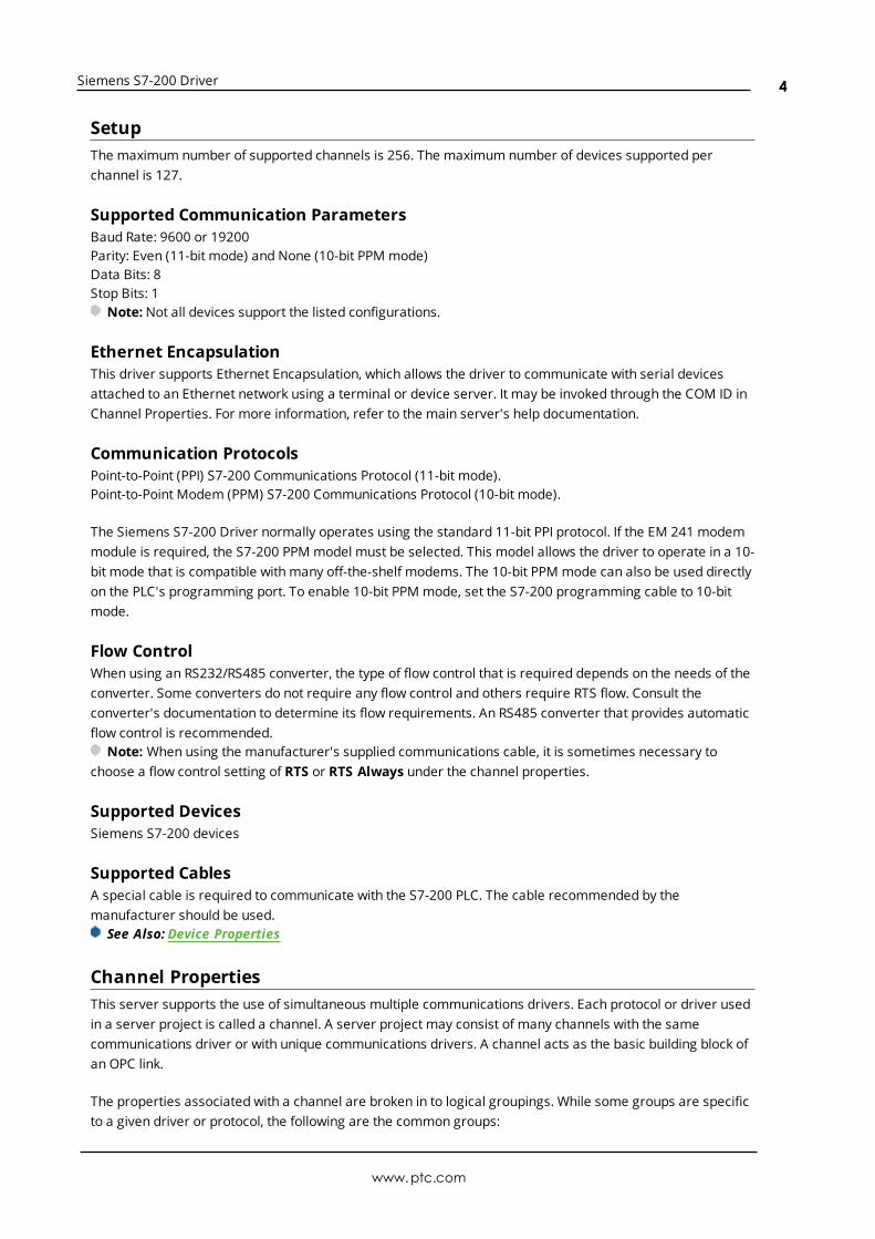
SetupThe maximum number of supported channels is 256. The maximum number of devices supported perchannel is 127.
Supported Communication ParametersBaud Rate: 9600 or 19200Parity: Even (11-bit mode) and None (10-bit PPM mode)Data Bits: 8Stop Bits: 1
Note: Not all devices support the listed configurations.
Ethernet EncapsulationThis driver supports Ethernet Encapsulation, which allows the driver to communicate with serial devicesattached to an Ethernet network using a terminal or device server. It may be invoked through the COM ID inChannel Properties. For more information, refer to the main server's help documentation.
Communication ProtocolsPoint-to-Point (PPI) S7-200 Communications Protocol (11-bit mode).Point-to-Point Modem (PPM) S7-200 Communications Protocol (10-bit mode).
The Siemens S7-200 Driver normally operates using the standard 11-bit PPI protocol. If the EM 241 modemmodule is required, the S7-200 PPM model must be selected. This model allows the driver to operate in a 10-bit mode that is compatible with many off-the-shelf modems. The 10-bit PPM mode can also be used directlyon the PLC's programming port. To enable 10-bit PPM mode, set the S7-200 programming cable to 10-bitmode.
Flow ControlWhen using an RS232/RS485 converter, the type of flow control that is required depends on the needs of theconverter. Some converters do not require any flow control and others require RTS flow. Consult theconverter's documentation to determine its flow requirements. An RS485 converter that provides automaticflow control is recommended.
Note: When using the manufacturer's supplied communications cable, it is sometimes necessary tochoose a flow control setting of RTS or RTS Always under the channel properties.
Supported DevicesSiemens S7-200 devices
Supported CablesA special cable is required to communicate with the S7-200 PLC. The cable recommended by themanufacturer should be used.
See Also: Device Properties
Channel PropertiesThis server supports the use of simultaneous multiple communications drivers. Each protocol or driver usedin a server project is called a channel. A server project may consist of many channels with the samecommunications driver or with unique communications drivers. A channel acts as the basic building block ofan OPC link.
The properties associated with a channel are broken in to logical groupings. While some groups are specificto a given driver or protocol, the following are the common groups:
www.ptc.com
4
Siemens S7-200 Driver
GeneralEthernet or Serial CommunicationsWrite OptimizationAdvanced
Channel Properties — GeneralThis server supports the use of simultaneous multiple communications drivers. Each protocol or driver usedin a server project is called a channel. A server project may consist of many channels with the samecommunications driver or with unique communications drivers. A channel acts as the basic building block ofan OPC link. This group is used to specify general channel properties, such as the identification attributesand operating mode.
Identification
Name: User-defined identity of this channel. In each server project, each channel name must be unique.Although names can be up to 256 characters, some client applications have a limited display window whenbrowsing the OPC server's tag space. The channel name is part of the OPC browser information.For information on reserved characters, refer to "How To... Properly Name a Channel, Device, Tag, and Tag
Group" in the server help.
Description: User-defined information about this channel. Many of these properties, including Description, have an associated system tag.
Driver: Selected protocol / driver for this channel. This property specifies the device driver that was selectedduring channel creation. It is a disabled setting in the channel properties.
Note: With the server's online full-time operation, these properties can be changed at any time. Thisincludes changing the channel name to prevent clients from registering data with the server. If a client hasalready acquired an item from the server before the channel name is changed, the items are unaffected. If,after the channel name has been changed, the client application releases the item and attempts to re-acquire using the old channel name, the item is not accepted. With this in mind, changes to the propertiesshould not be made once a large client application has been developed. Utilize the User Manager to preventoperators from changing properties and restrict access rights to server features.
Diagnostics
Diagnostics Capture: When enabled, this optionmakes the channel's diagnostic information available toOPC applications. Because the server's diagnostic features require a minimal amount of overheadprocessing, it is recommended that they be utilized when needed and disabled when not. The default isdisabled.Note: This property is disabled if the driver does not support diagnostics.For more information, refer to "Communication Diagnostics" in the server help.
www.ptc.com
5
Siemens S7-200 Driver
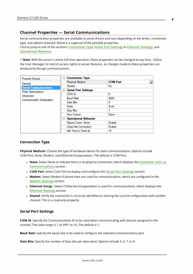
Channel Properties — Serial CommunicationsSerial communication properties are available to serial drivers and vary depending on the driver, connectiontype, and options selected. Below is a superset of the possible properties.Click to jump to one of the sections: Connection Type, Serial Port Settings or Ethernet Settings, andOperational Behavior.
Note: With the server's online full-time operation, these properties can be changed at any time. Utilizethe User Manager to restrict access rights to server features, as changes made to these properties cantemporarily disrupt communications.
Connection Type
Physical Medium: Choose the type of hardware device for data communications. Options includeCOM Port, None, Modem, and Ethernet Encapsulation. The default is COM Port.
l None: Select None to indicate there is no physical connection, which displays the Operation with noCommunications section.
l COM Port: Select Com Port to display and configure the Serial Port Settings section.
l Modem: Select Modem if phone lines are used for communications, which are configured in theModem Settings section.
l Ethernet Encap.: Select if Ethernet Encapsulation is used for communications, which displays theEthernet Settings section.
l Shared: Verify the connection is correctly identified as sharing the current configuration with anotherchannel. This is a read-only property.
Serial Port Settings
COM ID: Specify the Communications ID to be used when communicating with devices assigned to thechannel. The valid range is 1 to 9991 to 16. The default is 1.
Baud Rate: Specify the baud rate to be used to configure the selected communications port.
Data Bits: Specify the number of data bits per data word. Options include 5, 6, 7, or 8.
www.ptc.com
6
Siemens S7-200 Driver
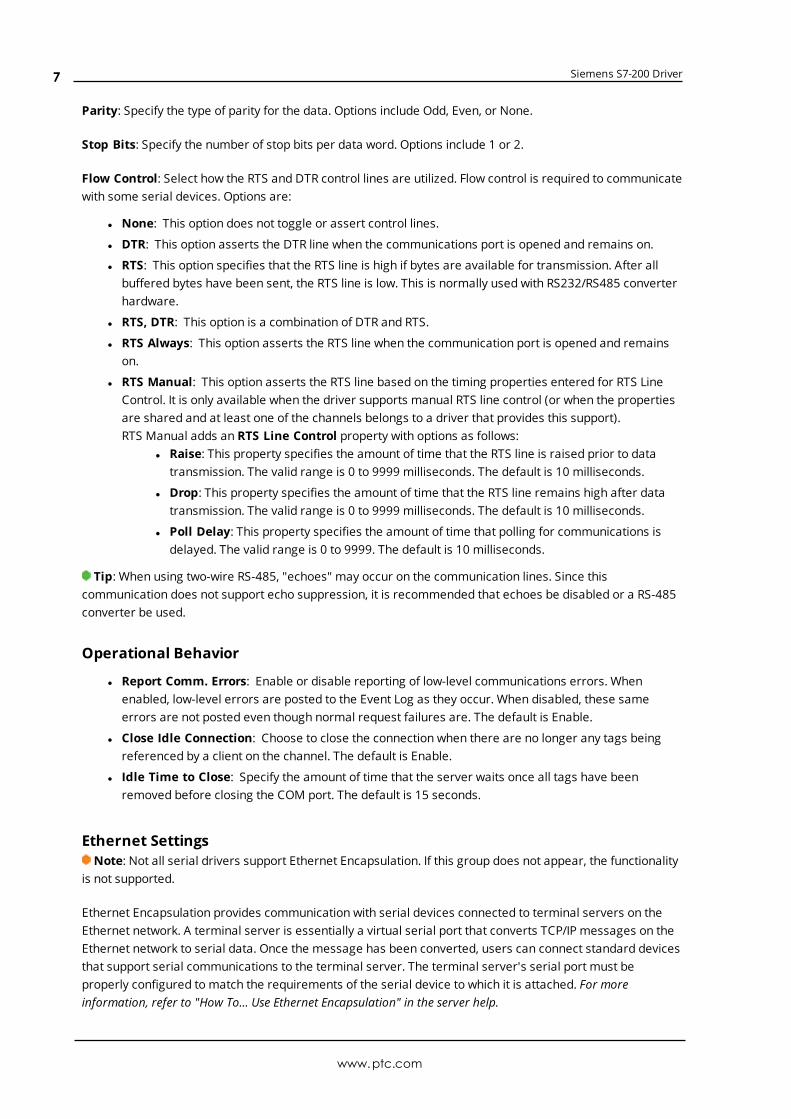
Parity: Specify the type of parity for the data. Options include Odd, Even, or None.
Stop Bits: Specify the number of stop bits per data word. Options include 1 or 2.
Flow Control: Select how the RTS and DTR control lines are utilized. Flow control is required to communicatewith some serial devices. Options are:
l None: This option does not toggle or assert control lines.
l DTR: This option asserts the DTR line when the communications port is opened and remains on.
l RTS: This option specifies that the RTS line is high if bytes are available for transmission. After allbuffered bytes have been sent, the RTS line is low. This is normally used with RS232/RS485 converterhardware.
l RTS, DTR: This option is a combination of DTR and RTS.
l RTS Always: This option asserts the RTS line when the communication port is opened and remainson.
l RTS Manual: This option asserts the RTS line based on the timing properties entered for RTS LineControl. It is only available when the driver supports manual RTS line control (or when the propertiesare shared and at least one of the channels belongs to a driver that provides this support).RTS Manual adds an RTS Line Control property with options as follows:
l Raise: This property specifies the amount of time that the RTS line is raised prior to datatransmission. The valid range is 0 to 9999 milliseconds. The default is 10 milliseconds.
l Drop: This property specifies the amount of time that the RTS line remains high after datatransmission. The valid range is 0 to 9999 milliseconds. The default is 10 milliseconds.
l Poll Delay: This property specifies the amount of time that polling for communications isdelayed. The valid range is 0 to 9999. The default is 10 milliseconds.
Tip: When using two-wire RS-485, "echoes" may occur on the communication lines. Since thiscommunication does not support echo suppression, it is recommended that echoes be disabled or a RS-485converter be used.
Operational Behavior
l Report Comm. Errors: Enable or disable reporting of low-level communications errors. Whenenabled, low-level errors are posted to the Event Log as they occur. When disabled, these sameerrors are not posted even though normal request failures are. The default is Enable.
l Close Idle Connection: Choose to close the connection when there are no longer any tags beingreferenced by a client on the channel. The default is Enable.
l Idle Time to Close: Specify the amount of time that the server waits once all tags have beenremoved before closing the COM port. The default is 15 seconds.
Ethernet SettingsNote: Not all serial drivers support Ethernet Encapsulation. If this group does not appear, the functionality
is not supported.
Ethernet Encapsulation provides communication with serial devices connected to terminal servers on theEthernet network. A terminal server is essentially a virtual serial port that converts TCP/IP messages on theEthernet network to serial data. Once the message has been converted, users can connect standard devicesthat support serial communications to the terminal server. The terminal server's serial port must beproperly configured to match the requirements of the serial device to which it is attached. For moreinformation, refer to "How To... Use Ethernet Encapsulation" in the server help.
www.ptc.com
7
Siemens S7-200 Driver
l Network Adapter: Indicate a network adapter to bind for Ethernet devices in this channel. Choose anetwork adapter to bind to or allow the OS to select the default.Specific drivers may display additional Ethernet Encapsulation properties. For more information, refer
to Channel Properties - Ethernet Encapsulation.
Modem Settings
l Modem: Specify the installed modem to be used for communications.
l Connect Timeout: Specify the amount of time to wait for connections to be established beforefailing a read or write. The default is 60 seconds.
l Modem Properties: Configure the modem hardware. When clicked, it opens vendor-specific modemproperties.
l Auto-Dial: Enables the automatic dialing of entries in the Phonebook. The default is Disable. Formore information, refer to "Modem Auto-Dial" in the server help.
l Report Comm. Errors: Enable or disable reporting of low-level communications errors. Whenenabled, low-level errors are posted to the Event Log as they occur. When disabled, these sameerrors are not posted even though normal request failures are. The default is Enable.
l Close Idle Connection: Choose to close the modem connection when there are no longer any tagsbeing referenced by a client on the channel. The default is Enable.
l Idle Time to Close: Specify the amount of time that the server waits once all tags have beenremoved before closing the modem connection. The default is 15 seconds.
Operation with no Communications
l Read Processing: Select the action to be taken when an explicit device read is requested. Optionsinclude Ignore and Fail. Ignore does nothing; Fail provides the client with an update that indicatesfailure. The default setting is Ignore.
Channel Properties — Write OptimizationsAs with any OPC server, writing data to the device may be the application's most important aspect. Theserver intends to ensure that the data written from the client application gets to the device on time. Giventhis goal, the server provides optimization properties that can be used to meet specific needs or improveapplication responsiveness.
Write Optimizations
Optimization Method: controls how write data is passed to the underlying communications driver. Theoptions are:
l Write All Values for All Tags: This option forces the server to attempt to write every value to thecontroller. In this mode, the server continues to gather write requests and add them to the server'sinternal write queue. The server processes the write queue and attempts to empty it by writing data
www.ptc.com
8
Siemens S7-200 Driver
to the device as quickly as possible. This mode ensures that everything written from the clientapplications is sent to the target device. This mode should be selected if the write operation order orthe write item's content must uniquely be seen at the target device.
l Write Only Latest Value for Non-Boolean Tags: Many consecutive writes to the same value canaccumulate in the write queue due to the time required to actually send the data to the device. If theserver updates a write value that has already been placed in the write queue, far fewer writes areneeded to reach the same final output value. In this way, no extra writes accumulate in the server'squeue. When the user stops moving the slide switch, the value in the device is at the correct value atvirtually the same time. As the mode states, any value that is not a Boolean value is updated in theserver's internal write queue and sent to the device at the next possible opportunity. This can greatlyimprove the application performance.
Note: This option does not attempt to optimize writes to Boolean values. It allows users tooptimize the operation of HMI data without causing problems with Boolean operations, such as amomentary push button.
l Write Only Latest Value for All Tags: This option takes the theory behind the second optimizationmode and applies it to all tags. It is especially useful if the application only needs to send the latestvalue to the device. This mode optimizes all writes by updating the tags currently in the write queuebefore they are sent. This is the default mode.
Duty Cycle: is used to control the ratio of write to read operations. The ratio is always based on one read forevery one to ten writes. The duty cycle is set to ten by default, meaning that ten writes occur for each readoperation. Although the application is performing a large number of continuous writes, it must be ensuredthat read data is still given time to process. A setting of one results in one read operation for every writeoperation. If there are no write operations to perform, reads are processed continuously. This allowsoptimization for applications with continuous writes versus a more balanced back and forth data flow.
Note: It is recommended that the application be characterized for compatibility with the writeoptimization enhancements before being used in a production environment.
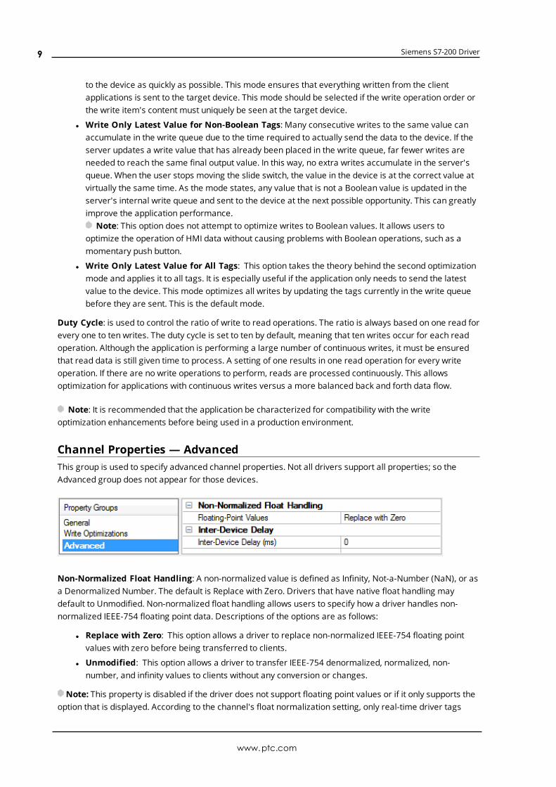
Channel Properties — AdvancedThis group is used to specify advanced channel properties. Not all drivers support all properties; so theAdvanced group does not appear for those devices.
Non-Normalized Float Handling: A non-normalized value is defined as Infinity, Not-a-Number (NaN), or asa Denormalized Number. The default is Replace with Zero. Drivers that have native float handling maydefault to Unmodified. Non-normalized float handling allows users to specify how a driver handles non-normalized IEEE-754 floating point data. Descriptions of the options are as follows:
l Replace with Zero: This option allows a driver to replace non-normalized IEEE-754 floating pointvalues with zero before being transferred to clients.
l Unmodified: This option allows a driver to transfer IEEE-754 denormalized, normalized, non-number, and infinity values to clients without any conversion or changes.
Note: This property is disabled if the driver does not support floating point values or if it only supports theoption that is displayed. According to the channel's float normalization setting, only real-time driver tags
www.ptc.com
9
Siemens S7-200 Driver
(such as values and arrays) are subject to float normalization. For example, EFM data is not affected by thissetting.
For more information on the floating point values, refer to "How To ... Work with Non-Normalized FloatingPoint Values" in the server help.
Inter-Device Delay: Specify the amount of time the communications channel waits to send new requests tothe next device after data is received from the current device on the same channel. Zero (0) disables thedelay.
Note: This property is not available for all drivers, models, and dependent settings.
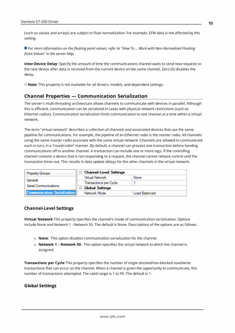
Channel Properties — Communication SerializationThe server's multi-threading architecture allows channels to communicate with devices in parallel. Althoughthis is efficient, communication can be serialized in cases with physical network restrictions (such asEthernet radios). Communication serialization limits communication to one channel at a time within a virtualnetwork.
The term "virtual network" describes a collection of channels and associated devices that use the samepipeline for communications. For example, the pipeline of an Ethernet radio is the master radio. All channelsusing the same master radio associate with the same virtual network. Channels are allowed to communicateeach in turn, in a “round-robin” manner. By default, a channel can process one transaction before handingcommunications off to another channel. A transaction can include one or more tags. If the controllingchannel contains a device that is not responding to a request, the channel cannot release control until thetransaction times out. This results in data update delays for the other channels in the virtual network.
Channel-Level Settings
Virtual Network This property specifies the channel's mode of communication serialization. Optionsinclude None and Network 1 - Network 50. The default is None. Descriptions of the options are as follows:
l None: This option disables communication serialization for the channel.
l Network 1 - Network 50: This option specifies the virtual network to which the channel isassigned.
Transactions per Cycle This property specifies the number of single blocked/non-blocked read/writetransactions that can occur on the channel. When a channel is given the opportunity to communicate, thisnumber of transactions attempted. The valid range is 1 to 99. The default is 1.
Global Settings
www.ptc.com
10
Siemens S7-200 Driver
l Network Mode: This property is used to control how channel communication is delegated. In LoadBalanced mode, each channel is given the opportunity to communicate in turn, one at a time. InPrioritymode, channels are given the opportunity to communicate according to the following rules(highest to lowest priority):
l Channels with pending writes have the highest priority.
l Channels with pending explicit reads (through internal plug-ins or external client interfaces)are prioritized based on the read’s priority.
l Scanned reads and other periodic events (driver specific).
The default is Load Balanced and affects all virtual networks and channels.
Devices that rely on unsolicited responses should not be placed in a virtual network. In situations wherecommunications must be serialized, it is recommended that Auto-Demotion be enabled.
Due to differences in the way that drivers read and write data (such as in single, blocked, or non-blockedtransactions); the application's Transactions per cycle property may need to be adjusted. When doing so,consider the following factors:
l Howmany tags must be read from each channel?
l How often is data written to each channel?
l Is the channel using a serial or Ethernet driver?
l Does the driver read tags in separate requests, or are multiple tags read in a block?
l Have the device's Timing properties (such as Request timeout and Fail after x successive timeouts)been optimized for the virtual network's communicationmedium?
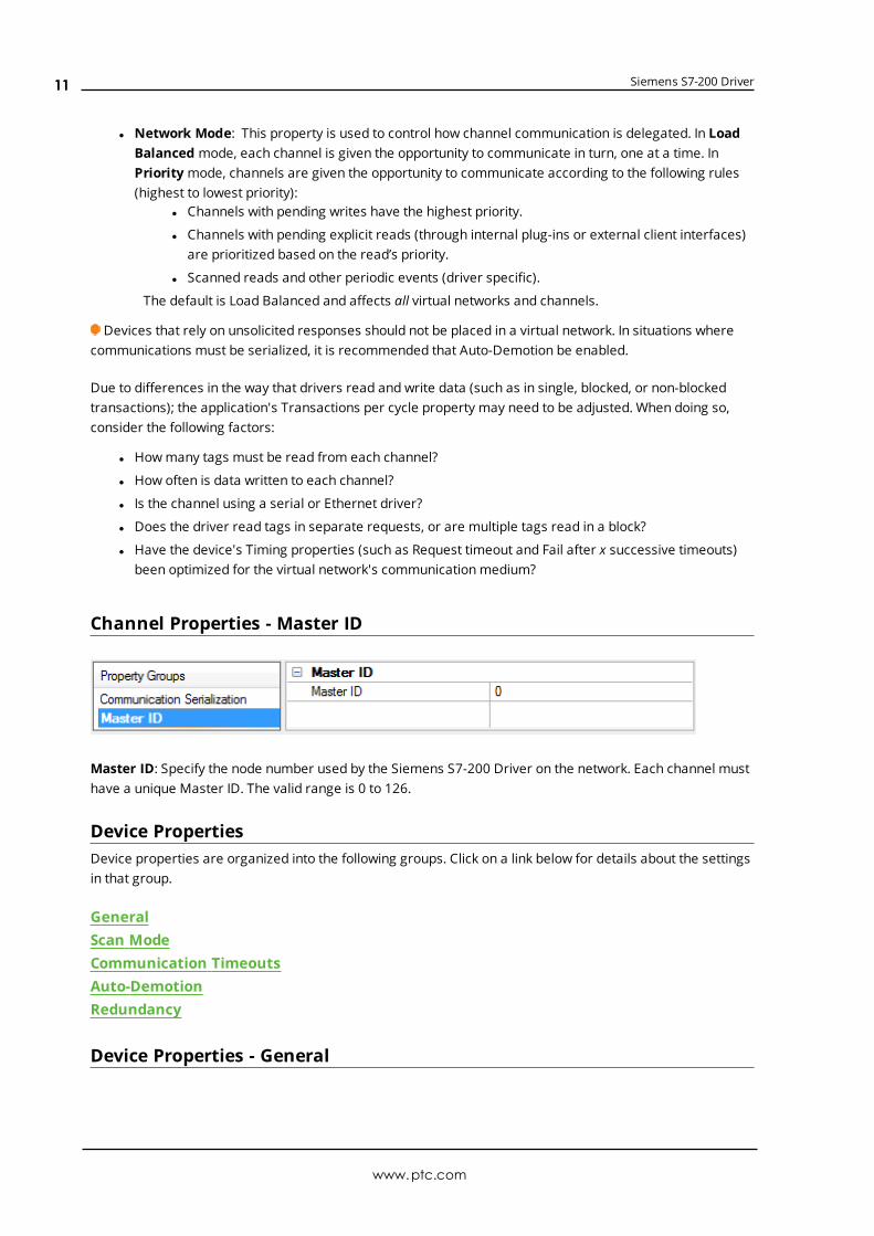
Channel Properties - Master ID
Master ID: Specify the node number used by the Siemens S7-200 Driver on the network. Each channel musthave a unique Master ID. The valid range is 0 to 126.
Device PropertiesDevice properties are organized into the following groups. Click on a link below for details about the settingsin that group.
GeneralScan ModeCommunication TimeoutsAuto-DemotionRedundancy
Device Properties - General
www.ptc.com
11
Siemens S7-200 Driver
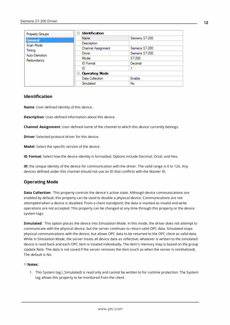
Identification
Name: User-defined identity of this device.
Description: User-defined information about this device.
Channel Assignment: User-defined name of the channel to which this device currently belongs.
Driver: Selected protocol driver for this device.
Model: Select the specific version of the device.
ID Format: Select how the device identity is formatted. Options include Decimal, Octal, and Hex.
ID: the unique identity of the device for communication with the driver. The valid range is 0 to 126. Anydevices defined under this channel should not use an ID that conflicts with the Master ID.
Operating Mode
Data Collection: This property controls the device's active state. Although device communications areenabled by default, this property can be used to disable a physical device. Communications are notattempted when a device is disabled. From a client standpoint, the data is marked as invalid and writeoperations are not accepted. This property can be changed at any time through this property or the devicesystem tags.
Simulated: This option places the device into Simulation Mode. In this mode, the driver does not attempt tocommunicate with the physical device, but the server continues to return valid OPC data. Simulated stopsphysical communications with the device, but allows OPC data to be returned to the OPC client as valid data.While in Simulation Mode, the server treats all device data as reflective: whatever is written to the simulateddevice is read back and each OPC item is treated individually. The item's memory map is based on the groupUpdate Rate. The data is not saved if the server removes the item (such as when the server is reinitialized).The default is No.
Notes:
1. This System tag (_Simulated) is read only and cannot be written to for runtime protection. The Systemtag allows this property to be monitored from the client.
www.ptc.com
12
Siemens S7-200 Driver
2. In Simulationmode, the item's memory map is based on client update rate(s) (Group Update Rate forOPC clients or Scan Rate for native and DDE interfaces). This means that two clients that referencethe same item with different update rates return different data.
Simulation Mode is for test and simulation purposes only. It should never be used in a productionenvironment.
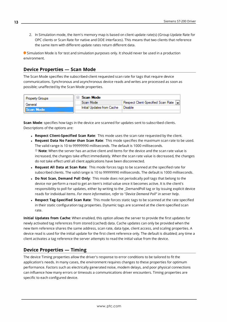
Device Properties — Scan ModeThe ScanMode specifies the subscribed-client requested scan rate for tags that require devicecommunications. Synchronous and asynchronous device reads and writes are processed as soon aspossible; unaffected by the ScanMode properties.
Scan Mode: specifies how tags in the device are scanned for updates sent to subscribed clients.Descriptions of the options are:
l Respect Client-Specified Scan Rate: This mode uses the scan rate requested by the client.l Request Data No Faster than Scan Rate: This mode specifies the maximum scan rate to be used.
The valid range is 10 to 99999990 milliseconds. The default is 1000 milliseconds.Note: When the server has an active client and items for the device and the scan rate value is
increased, the changes take effect immediately. When the scan rate value is decreased, the changesdo not take effect until all client applications have been disconnected.
l Request All Data at Scan Rate: This mode forces tags to be scanned at the specified rate forsubscribed clients. The valid range is 10 to 99999990 milliseconds. The default is 1000 milliseconds.
l Do Not Scan, Demand Poll Only: This mode does not periodically poll tags that belong to thedevice nor perform a read to get an item's initial value once it becomes active. It is the client'sresponsibility to poll for updates, either by writing to the _DemandPoll tag or by issuing explicit devicereads for individual items. For more information, refer to "Device Demand Poll" in server help.
l Respect Tag-Specified Scan Rate: This mode forces static tags to be scanned at the rate specifiedin their static configuration tag properties. Dynamic tags are scanned at the client-specified scanrate.
Initial Updates from Cache: When enabled, this option allows the server to provide the first updates fornewly activated tag references from stored (cached) data. Cache updates can only be provided when thenew item reference shares the same address, scan rate, data type, client access, and scaling properties. Adevice read is used for the initial update for the first client reference only. The default is disabled; any time aclient activates a tag reference the server attempts to read the initial value from the device.
Device Properties — TimingThe device Timing properties allow the driver's response to error conditions to be tailored to fit theapplication's needs. In many cases, the environment requires changes to these properties for optimumperformance. Factors such as electrically generated noise, modem delays, and poor physical connectionscan influence howmany errors or timeouts a communications driver encounters. Timing properties arespecific to each configured device.
www.ptc.com
13
Siemens S7-200 Driver
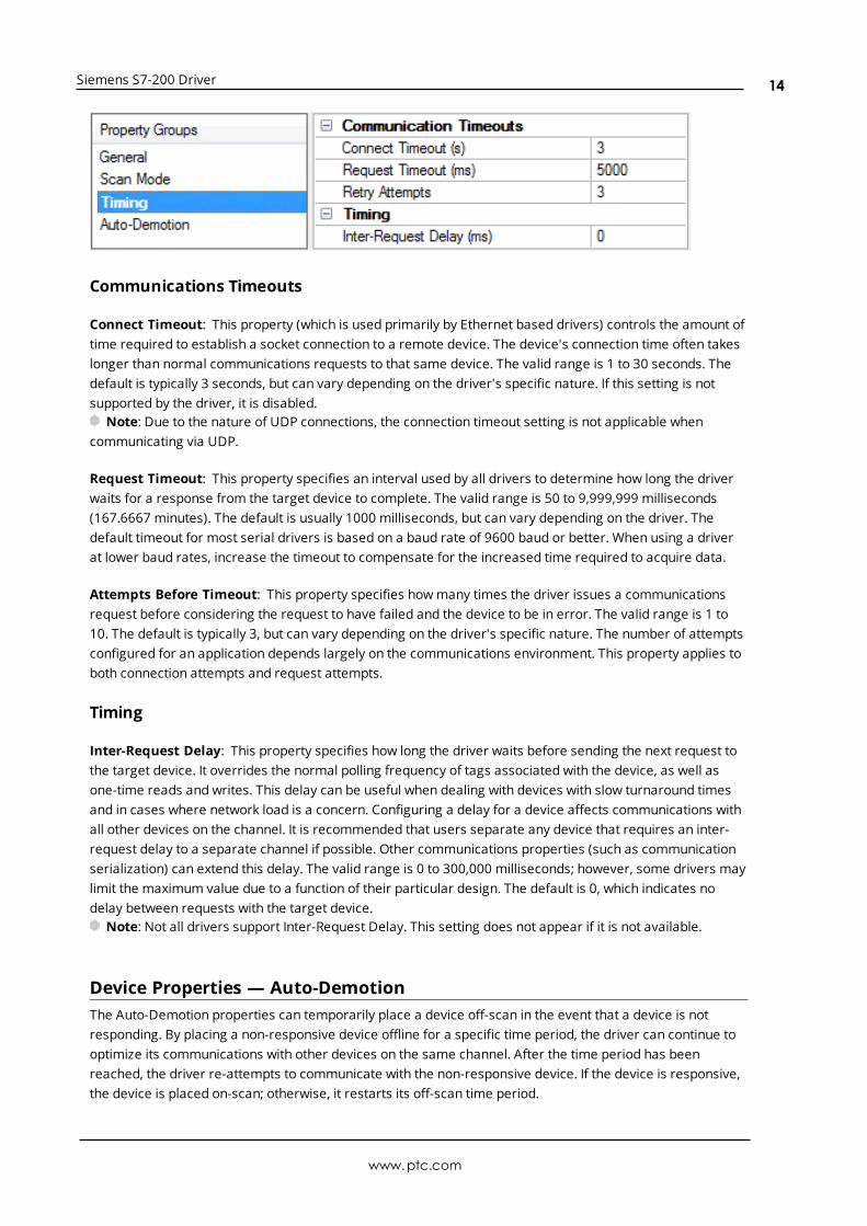
Communications Timeouts
Connect Timeout: This property (which is used primarily by Ethernet based drivers) controls the amount oftime required to establish a socket connection to a remote device. The device's connection time often takeslonger than normal communications requests to that same device. The valid range is 1 to 30 seconds. Thedefault is typically 3 seconds, but can vary depending on the driver's specific nature. If this setting is notsupported by the driver, it is disabled.
Note: Due to the nature of UDP connections, the connection timeout setting is not applicable whencommunicating via UDP.
Request Timeout: This property specifies an interval used by all drivers to determine how long the driverwaits for a response from the target device to complete. The valid range is 50 to 9,999,999 milliseconds(167.6667 minutes). The default is usually 1000 milliseconds, but can vary depending on the driver. Thedefault timeout for most serial drivers is based on a baud rate of 9600 baud or better. When using a driverat lower baud rates, increase the timeout to compensate for the increased time required to acquire data.
Attempts Before Timeout: This property specifies howmany times the driver issues a communicationsrequest before considering the request to have failed and the device to be in error. The valid range is 1 to10. The default is typically 3, but can vary depending on the driver's specific nature. The number of attemptsconfigured for an application depends largely on the communications environment. This property applies toboth connection attempts and request attempts.
Timing
Inter-Request Delay: This property specifies how long the driver waits before sending the next request tothe target device. It overrides the normal polling frequency of tags associated with the device, as well asone-time reads and writes. This delay can be useful when dealing with devices with slow turnaround timesand in cases where network load is a concern. Configuring a delay for a device affects communications withall other devices on the channel. It is recommended that users separate any device that requires an inter-request delay to a separate channel if possible. Other communications properties (such as communicationserialization) can extend this delay. The valid range is 0 to 300,000 milliseconds; however, some drivers maylimit the maximum value due to a function of their particular design. The default is 0, which indicates nodelay between requests with the target device.
Note: Not all drivers support Inter-Request Delay. This setting does not appear if it is not available.
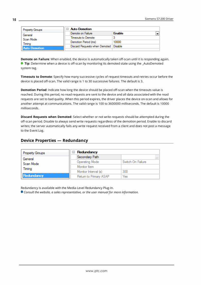
Device Properties — Auto-DemotionThe Auto-Demotion properties can temporarily place a device off-scan in the event that a device is notresponding. By placing a non-responsive device offline for a specific time period, the driver can continue tooptimize its communications with other devices on the same channel. After the time period has beenreached, the driver re-attempts to communicate with the non-responsive device. If the device is responsive,the device is placed on-scan; otherwise, it restarts its off-scan time period.
www.ptc.com
14
Siemens S7-200 Driver
Demote on Failure: When enabled, the device is automatically taken off-scan until it is responding again.Tip: Determine when a device is off-scan by monitoring its demoted state using the _AutoDemoted
system tag.
Timeouts to Demote: Specify howmany successive cycles of request timeouts and retries occur before thedevice is placed off-scan. The valid range is 1 to 30 successive failures. The default is 3.
Demotion Period: Indicate how long the device should be placed off-scan when the timeouts value isreached. During this period, no read requests are sent to the device and all data associated with the readrequests are set to bad quality. When this period expires, the driver places the device on-scan and allows foranother attempt at communications. The valid range is 100 to 3600000 milliseconds. The default is 10000milliseconds.
Discard Requests when Demoted: Select whether or not write requests should be attempted during theoff-scan period. Disable to always send write requests regardless of the demotion period. Enable to discardwrites; the server automatically fails any write request received from a client and does not post a messageto the Event Log.
Device Properties — Redundancy
Redundancy is available with the Media-Level Redundancy Plug-In.Consult the website, a sales representative, or the user manual for more information.
www.ptc.com
15
Siemens S7-200 Driver
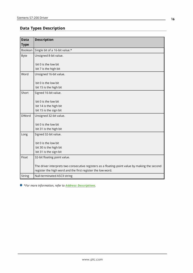
Data Types Description
DataType
Description
Boolean Single bit of a 16-bit value.*
Byte Unsigned 8-bit value.
bit 0 is the low bitbit 7 is the high bit
Word Unsigned 16-bit value.
bit 0 is the low bitbit 15 is the high bit
Short Signed 16-bit value.
bit 0 is the low bitbit 14 is the high bitbit 15 is the sign bit
DWord Unsigned 32-bit value.
bit 0 is the low bitbit 31 is the high bit
Long Signed 32-bit value.
bit 0 is the low bitbit 30 is the high bitbit 31 is the sign bit
Float 32-bit floating point value.
The driver interprets two consecutive registers as a floating-point value by making the secondregister the high word and the first register the low word.
String Null-terminated ASCII string
*For more information, refer to Address Descriptions.
www.ptc.com
16
Siemens S7-200 Driver
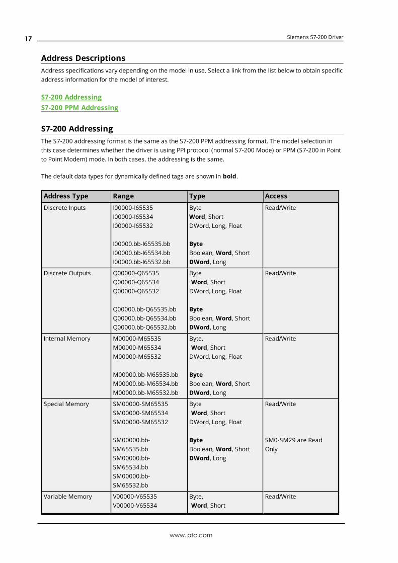
Address DescriptionsAddress specifications vary depending on the model in use. Select a link from the list below to obtain specificaddress information for the model of interest.
S7-200 AddressingS7-200 PPM Addressing
S7-200 AddressingThe S7-200 addressing format is the same as the S7-200 PPM addressing format. The model selection inthis case determines whether the driver is using PPI protocol (normal S7-200 Mode) or PPM (S7-200 in Pointto Point Modem) mode. In both cases, the addressing is the same.
The default data types for dynamically defined tags are shown in bold.
Address Type Range Type Access
Discrete Inputs I00000-I65535I00000-I65534I00000-I65532
I00000.bb-I65535.bbI00000.bb-I65534.bbI00000.bb-I65532.bb
ByteWord, ShortDWord, Long, Float
ByteBoolean, Word, ShortDWord, Long
Read/Write
Discrete Outputs Q00000-Q65535Q00000-Q65534Q00000-Q65532
Q00000.bb-Q65535.bbQ00000.bb-Q65534.bbQ00000.bb-Q65532.bb
ByteWord, ShortDWord, Long, Float
ByteBoolean, Word, ShortDWord, Long
Read/Write
Internal Memory M00000-M65535M00000-M65534M00000-M65532
M00000.bb-M65535.bbM00000.bb-M65534.bbM00000.bb-M65532.bb
Byte,Word, ShortDWord, Long, Float
ByteBoolean, Word, ShortDWord, Long
Read/Write
Special Memory SM00000-SM65535SM00000-SM65534SM00000-SM65532
SM00000.bb-SM65535.bbSM00000.bb-SM65534.bbSM00000.bb-SM65532.bb
ByteWord, ShortDWord, Long, Float
ByteBoolean, Word, ShortDWord, Long
Read/Write
SM0-SM29 are ReadOnly
Variable Memory V00000-V65535V00000-V65534
Byte,Word, Short
Read/Write
www.ptc.com
17
Siemens S7-200 Driver
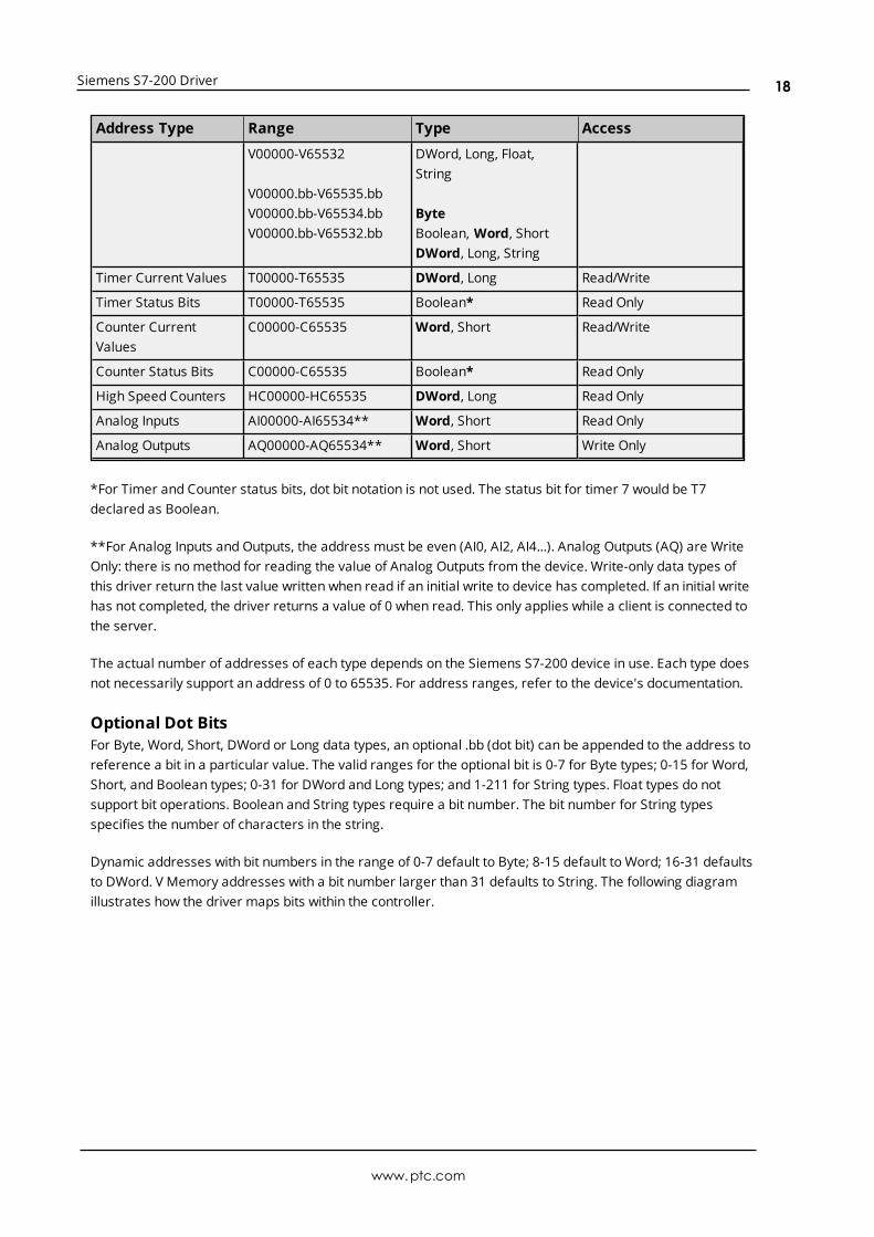
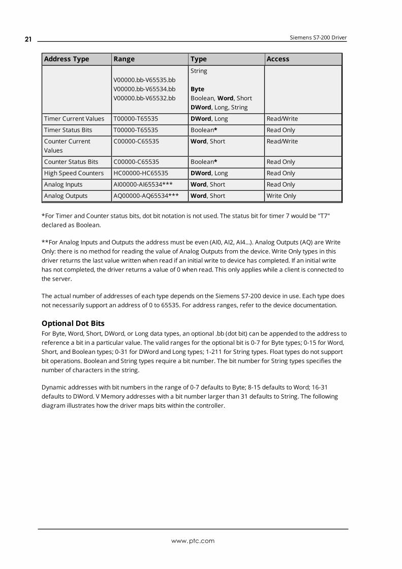
Address Type Range Type Access
V00000-V65532
V00000.bb-V65535.bbV00000.bb-V65534.bbV00000.bb-V65532.bb
DWord, Long, Float,String
ByteBoolean, Word, ShortDWord, Long, String
Timer Current Values T00000-T65535 DWord, Long Read/Write
Timer Status Bits T00000-T65535 Boolean* Read Only
Counter CurrentValues
C00000-C65535 Word, Short Read/Write
Counter Status Bits C00000-C65535 Boolean* Read Only
High Speed Counters HC00000-HC65535 DWord, Long Read Only
Analog Inputs AI00000-AI65534** Word, Short Read Only
Analog Outputs AQ00000-AQ65534** Word, Short Write Only
*For Timer and Counter status bits, dot bit notation is not used. The status bit for timer 7 would be T7declared as Boolean.
**For Analog Inputs and Outputs, the address must be even (AI0, AI2, AI4...). Analog Outputs (AQ) are WriteOnly: there is no method for reading the value of Analog Outputs from the device. Write-only data types ofthis driver return the last value written when read if an initial write to device has completed. If an initial writehas not completed, the driver returns a value of 0 when read. This only applies while a client is connected tothe server.
The actual number of addresses of each type depends on the Siemens S7-200 device in use. Each type doesnot necessarily support an address of 0 to 65535. For address ranges, refer to the device's documentation.
Optional Dot BitsFor Byte, Word, Short, DWord or Long data types, an optional .bb (dot bit) can be appended to the address toreference a bit in a particular value. The valid ranges for the optional bit is 0-7 for Byte types; 0-15 for Word,Short, and Boolean types; 0-31 for DWord and Long types; and 1-211 for String types. Float types do notsupport bit operations. Boolean and String types require a bit number. The bit number for String typesspecifies the number of characters in the string.
Dynamic addresses with bit numbers in the range of 0-7 default to Byte; 8-15 default to Word; 16-31 defaultsto DWord. V Memory addresses with a bit number larger than 31 defaults to String. The following diagramillustrates how the driver maps bits within the controller.
www.ptc.com
18
Siemens S7-200 Driver
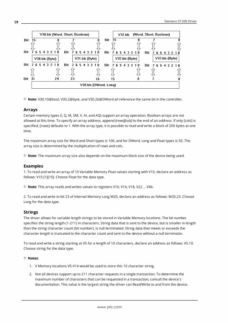
Note: V30.10@bool, V30.2@byte, and V30.26@DWord all reference the same bit in the controller.
ArraysCertain memory types (I, Q, M, SM, V, AI, and AQ) support an array operation. Boolean arrays are notallowed at this time. To specify an array address, append [rows][cols] to the end of an address. If only [cols] isspecified, [rows] defaults to 1. With the array type, it is possible to read and write a block of 200 bytes at onetime.
The maximum array size for Word and Short types is 100, and for DWord, Long and Float types is 50. Thearray size is determined by the multiplication of rows and cols.
Note: The maximum array size also depends on the maximum block size of the device being used.
Examples1. To read and write an array of 10 Variable Memory Float values starting with V10, declare an address asfollows: V10 [1][10]. Choose Float for the data type.
Note: This array reads and writes values to registers V10, V14, V18, V22 ... V46.
2. To read and write to bit 23 of Internal Memory Long M20, declare an address as follows: M20.23. ChooseLong for the data type.
StringsThe driver allows for variable length strings to be stored in Variable Memory locations. The bit numberspecifies the string length (1-211) in characters. String data that is sent to the device, but is smaller in lengththan the string character count (bit number), is null terminated. String data that meets or exceeds thecharacter length is truncated to the character count and sent to the device without a null terminator.
To read and write a string starting at V5 for a length of 10 characters, declare an address as follows: V5.10.Choose string for the data type.
Notes:
1. V Memory locations V5-V14 would be used to store this 10 character string.
2. Not all devices support up to 211 character requests in a single transaction. To determine themaximum number of characters that can be requested in a transaction, consult the device'sdocumentation. This value is the largest string the driver can Read/Write to and from the device.
www.ptc.com
19
Siemens S7-200 Driver
Caution: Whenmodifying Word, Short, DWord, Long and Float types remember that each address startsat a byte offset within the device. Therefore, Words V0 and V1 overlap at byte 1. Writing to V0 modifies thevalue held in V1. Similarly, DWord, Long, and Float types can also overlap. It is recommended that thesememory types be used so that overlapping does not occur. As an example, when using DWords, use V0, V4,V8, and so on to prevent overlapping bytes.
S7-200 PPM AddressingThe S7-200 PPM addressing format is the same as the S7-200 addressing format. The model selection inthis case determines whether the driver is using PPI protocol (normal S7-200 Mode) or PPM (S7-200 in Pointto Point Modem) mode. In both cases, the addressing is the same. PPM mode is used when the target PLC isconnected via the EM241 Modemmodule or via the programming port running in 10-bit mode.
The default data types for dynamically defined tags are shown in bold.
Address Type Range Type Access
Discrete Inputs I00000-I65535I00000-I65534I00000-I65532
I00000.bb-I65535.bbI00000.bb-I65534.bbI00000.bb-I65532.bb
ByteWord, ShortDWord, Long, Float
ByteBoolean, Word, ShortDWord, Long
Read/Write
Discrete Outputs Q00000-Q65535Q00000-Q65534Q00000-Q65532
Q00000.bb-Q65535.bbQ00000.bb-Q65534.bbQ00000.bb-Q65532.bb
ByteWord, ShortDWord, Long, Float
ByteBoolean, Word, ShortDWord, Long
Read/Write
Internal Memory M00000-M65535M00000-M65534M00000-M65532
M00000.bb-M65535.bbM00000.bb-M65534.bbM00000.bb-M65532.bb
ByteWord, ShortDWord, Long, Float
ByteBoolean, Word, ShortDWord, Long
Read/Write
Special Memory SM00000-SM65535SM00000-SM65534SM00000-SM65532
SM00000.bb-SM65535.bbSM00000.bb-SM65534.bbSM00000.bb-SM65532.bb
ByteWord, ShortDWord, Long, Float
ByteBoolean, Word, ShortDWord, Long
Read/Write
SM0-SM29 are ReadOnly
Variable Memory V00000-V65535V00000-V65534V00000-V65532
ByteWord, ShortDWord, Long, Float,
Read/Write
www.ptc.com
20
Siemens S7-200 Driver
Address Type Range Type Access
V00000.bb-V65535.bbV00000.bb-V65534.bbV00000.bb-V65532.bb
String
ByteBoolean, Word, ShortDWord, Long, String
Timer Current Values T00000-T65535 DWord, Long Read/Write
Timer Status Bits T00000-T65535 Boolean* Read Only
Counter CurrentValues
C00000-C65535 Word, Short Read/Write
Counter Status Bits C00000-C65535 Boolean* Read Only
High Speed Counters HC00000-HC65535 DWord, Long Read Only
Analog Inputs AI00000-AI65534*** Word, Short Read Only
Analog Outputs AQ00000-AQ65534*** Word, Short Write Only
*For Timer and Counter status bits, dot bit notation is not used. The status bit for timer 7 would be "T7"declared as Boolean.
**For Analog Inputs and Outputs the address must be even (AI0, AI2, AI4...). Analog Outputs (AQ) are WriteOnly: there is no method for reading the value of Analog Outputs from the device. Write Only types in thisdriver returns the last value written when read if an initial write to device has completed. If an initial writehas not completed, the driver returns a value of 0 when read. This only applies while a client is connected tothe server.
The actual number of addresses of each type depends on the Siemens S7-200 device in use. Each type doesnot necessarily support an address of 0 to 65535. For address ranges, refer to the device documentation.
Optional Dot BitsFor Byte, Word, Short, DWord, or Long data types, an optional .bb (dot bit) can be appended to the address toreference a bit in a particular value. The valid ranges for the optional bit is 0-7 for Byte types; 0-15 for Word,Short, and Boolean types; 0-31 for DWord and Long types; 1-211 for String types. Float types do not supportbit operations. Boolean and String types require a bit number. The bit number for String types specifies thenumber of characters in the string.
Dynamic addresses with bit numbers in the range of 0-7 defaults to Byte; 8-15 defaults to Word; 16-31defaults to DWord. V Memory addresses with a bit number larger than 31 defaults to String. The followingdiagram illustrates how the driver maps bits within the controller.
www.ptc.com
21
Siemens S7-200 Driver
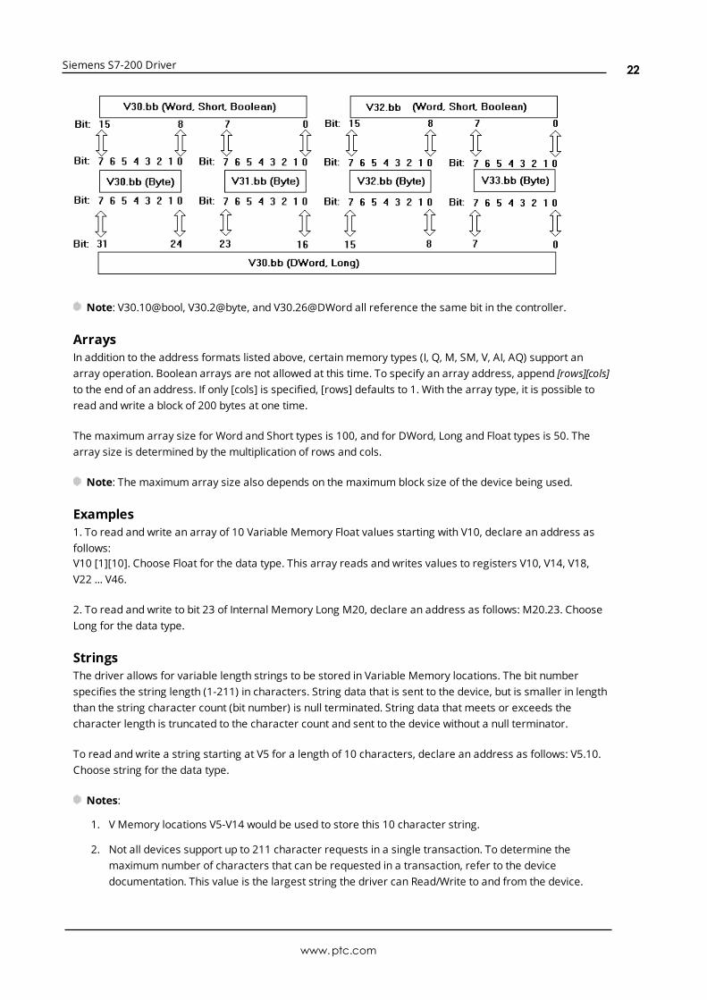
Note: V30.10@bool, V30.2@byte, and V30.26@DWord all reference the same bit in the controller.
ArraysIn addition to the address formats listed above, certain memory types (I, Q, M, SM, V, AI, AQ) support anarray operation. Boolean arrays are not allowed at this time. To specify an array address, append [rows][cols]to the end of an address. If only [cols] is specified, [rows] defaults to 1. With the array type, it is possible toread and write a block of 200 bytes at one time.
The maximum array size for Word and Short types is 100, and for DWord, Long and Float types is 50. Thearray size is determined by the multiplication of rows and cols.
Note: The maximum array size also depends on the maximum block size of the device being used.
Examples1. To read and write an array of 10 Variable Memory Float values starting with V10, declare an address asfollows:V10 [1][10]. Choose Float for the data type. This array reads and writes values to registers V10, V14, V18,V22 ... V46.
2. To read and write to bit 23 of Internal Memory Long M20, declare an address as follows: M20.23. ChooseLong for the data type.
StringsThe driver allows for variable length strings to be stored in Variable Memory locations. The bit numberspecifies the string length (1-211) in characters. String data that is sent to the device, but is smaller in lengththan the string character count (bit number) is null terminated. String data that meets or exceeds thecharacter length is truncated to the character count and sent to the device without a null terminator.
To read and write a string starting at V5 for a length of 10 characters, declare an address as follows: V5.10.Choose string for the data type.
Notes:
1. V Memory locations V5-V14 would be used to store this 10 character string.
2. Not all devices support up to 211 character requests in a single transaction. To determine themaximum number of characters that can be requested in a transaction, refer to the devicedocumentation. This value is the largest string the driver can Read/Write to and from the device.
www.ptc.com
22

Siemens S7-200 Driver
Whenmodifying Word, Short, DWord, Long and Float types remember that each address starts at a byteoffset within the device. Therefore, Words V0 and V1 overlap at byte 1. Writing to V0 modifies the value heldin V1. Similarly, DWord, Long, and Float types can also overlap. It is recommended that these memory typesbe used so that overlapping does not occur. For example, when using DWords, use V0, V4, V8 ... and so on, toprevent overlapping bytes.
www.ptc.com
23
Siemens S7-200 Driver
Event Log MessagesThe following information concerns messages posted to the Event Log pane in the main user interface.Consult the server help on filtering and sorting the Event Log detail view. Server help contains manycommonmessages, so should also be searched. Generally, the type of message (informational, warning)and troubleshooting information is provided whenever possible.
Block may have addresses out of range. | Block start address ='<address>', Block size = <count> (bytes).Error Type:Warning
Possible Cause:An attempt has beenmade to reference a block of memory that contains at least one non-existent locationin the specified device.
Possible Solution:Verify that the tags assigned to addresses are within the specified range on the device and eliminate anythat reference invalid locations.
Error Mask Definitions
B = Hardware break detectedF = Framing errorE= I/O errorO = Character buffer overrunR = RX buffer overrunP = Received byte parity errorT = TX buffer full
www.ptc.com
24
Siemens S7-200 Driver
ResourcesIn addition to this user manual, there are a variety of resources available to assist customers, answerquestions, provide more detail about specific implementations, or help with troubleshooting specific issues.
Knowledge BaseWhitepapersConnectivity GuidesTechnical NotesTraining ProgramsTraining VideosKepware Technical SupportPTC Technical Support
www.ptc.com
25
Siemens S7-200 Driver
Index
A
Address Descriptions 17
Advanced Channel Properties 9
Analog Inputs 18, 21
Analog Outputs 18, 21
Arrays 19, 22
Attempts Before Timeout 14
Auto Dial 8
B
Baud Rate 6
Block may have addresses out of range. | Block start address = '<address>', Block size = <count>(bytes). 24
Boolean 16
Byte 16
C
Channel Assignment 12
Channel Properties 4
Channel Properties - General 5
Channel Properties — Write Optimizations 8
Close Idle Connection 7-8
COM ID 6
Communication Protocols 4
Communication Serialization 10
Communications Timeouts 13-14
Connect Timeout 14
Connection Type 6
Counter Current Values 18, 21
Counter Status Bits 18, 21
www.ptc.com
26
Siemens S7-200 Driver
D
Data Bits 6
Data Collection 12
Data Types Description 16
Demote on Failure 15
Demotion Period 15
Device Properties 11
Device Properties — Auto-Demotion 14
Diagnostics 5
Discard Requests when Demoted 15
Discrete Inputs 17, 20
Discrete Outputs 17, 20
Do Not Scan, Demand Poll Only 13
Dot Bits 18, 21
Driver 5, 12
Duty Cycle 9
DWord 16
E
Error Mask Definitions 24
Event Log Messages 24
F
Float 16
Flow Control 4, 7
Framing 24
G
Global Settings 10
H
Hardware 24
www.ptc.com
27
Siemens S7-200 Driver
High Speed Counters 18, 21
I
I/O 24
ID 12
ID Format 12
Identification 11
Idle Time to Close 7-8
IEEE-754 floating point 9
Initial Updates from Cache 13
Inter-Request Delay 14
Internal Memory 17, 20
L
Load Balanced 11
Long 16
M
Master ID 11
Model 12
Modem 8
N
Network 4
Network Adapter 8
Network Mode 11
Non-Normalized Float Handling 9
O
OPC Client 3
Operational Behavior 7
Optimization Method 8
Overrun 24
www.ptc.com
28
Siemens S7-200 Driver
Overview 3
P
Parity 7, 24
Physical Medium 6
Point-to-Point (PPI) 4
Point-to-Point Modem (PPM) 4
PPI programming cable 3
Priority 11
R
Read Processing 8
Redundancy 15
Report Comm. Errors 7-8
Request All Data at Scan Rate 13
Request Data No Faster than Scan Rate 13
Request Timeout 14
Resources 25
Respect Client-Specified Scan Rate 13
Respect Tag-Specified Scan Rate 13
RS232 4
RS485 4
RX buffer overrun 24
S
S7-200 Addressing 17
S7-200 PPM Addressing 20
ScanMode 13
Serial Communications 6
Serial Port Settings 6
Setup 4
Short 16
Siemens S7-200 device 3
Signed 16
Simulated 12
www.ptc.com
29
Siemens S7-200 Driver
Special Memory 17, 20
Stop Bits 7
String 16
Strings 19, 22
Supported Cables 4
Supported Communication Parameters 4
Supported Devices 4
T
Timeouts to Demote 15
Timer Current Values 18, 21
Timer Status Bits 18, 21
Transactions 10
TX buffer 24
U
Unsigned 16
V
Variable Memory 17, 20
Virtual Network 10
W
Word 16
Write All Values for All Tags 8
Write Only Latest Value for All Tags 9
Write Only Latest Value for Non-Boolean Tags 9
Write Optimizations 8
www.ptc.com
30