Embed Size (px)
Citation preview

CODESYS Driver
© 2019 PTC Inc. All Rights Reserved.
CODESYS Driver
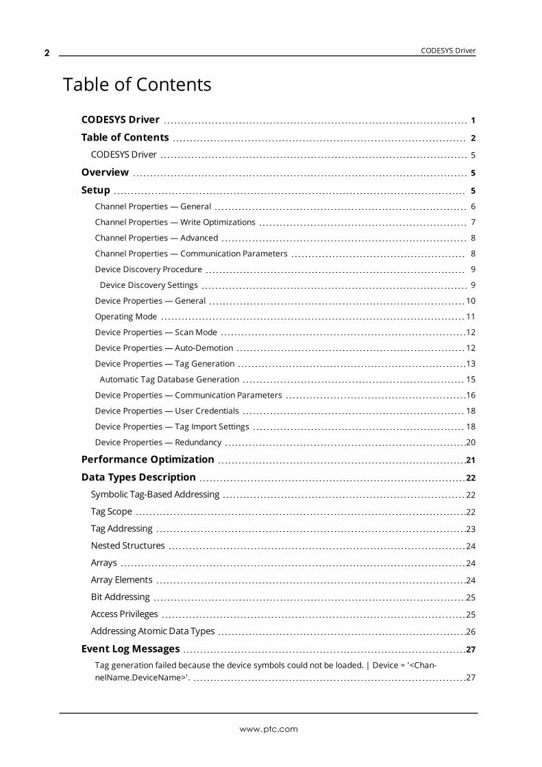
Table of Contents
CODESYS Driver 1
Table of Contents 2
CODESYS Driver 5
Overview 5
Setup 5
Channel Properties — General 6
Channel Properties — Write Optimizations 7
Channel Properties — Advanced 8
Channel Properties — Communication Parameters 8
Device Discovery Procedure 9
Device Discovery Settings 9
Device Properties — General 10
Operating Mode 11
Device Properties — ScanMode 12
Device Properties — Auto-Demotion 12
Device Properties — Tag Generation 13
Automatic Tag Database Generation 15
Device Properties — Communication Parameters 16
Device Properties — User Credentials 18
Device Properties — Tag Import Settings 18
Device Properties — Redundancy 20
Performance Optimization 21
Data Types Description 22
Symbolic Tag-Based Addressing 22
Tag Scope 22
Tag Addressing 23
Nested Structures 24
Arrays 24
Array Elements 24
Bit Addressing 25
Access Privileges 25
Addressing Atomic Data Types 26
Event Log Messages 27
Tag generation failed because the device symbols could not be loaded. | Device = '<Chan-nelName.DeviceName>'. 27
www.ptc.com
2

CODESYS Driver
Tag generation failed because communications could not be established with the device. | Device= '<ChannelName.DeviceName>'. 27
Tag generation failed because an unexpected failure occurred. | Device = '<Chan-nelName.DeviceName>'. 27
Internal Error. An unexpected error occurred. Resetting the PLC connection. | Transaction info ='<Transaction Type and Details>'. 28
Device discovery failed because an unexpected failure occurred. 28
Error occurred while attempting to write tag. Unable to connect to the device. | Tag address ='<.mystruct.innerstruct.tag>'. 28
Failed to browse tags. 29
Error occurred while attempting to connect to device. Failed to retrieve symbol list from device orfile. 29
Internal error occurred while attempting to read tag. | Tag address = '<.my-struct.innerstruct.tag>'. 29
Internal error occurred while attempting to write tag. | Tag address = '<.my-struct.innerstruct.tag>'. 29
Error occurred while attempting to read tag. Unsupported data type or invalid address specified.| Tag address = '<.mystruct.innerstruct.tag>', data type = '<type>'. 30
Error occurred while attempting to read tag. The specified tag address was not found on thedevice. | Tag address = '<.mystruct.innerstruct.tag>'. 30
Error occurred while attempting to write tag. The specified tag address was not found on thedevice. | Tag address = '<.mystruct.innerstruct.tag>'. 30
Error occurred while attempting to read tag. The specified server data type is not compatible withthe device data type. | Tag address = '<.mystruct.innerstruct.tag>', server data type = '<type>',device data type = '<type>'. 31
Error occurred while attempting to write tag. The specified server data type is not compatible withthe device data type. | Tag address = '<.mystruct.innerstruct.tag>', server data type = '<type>',device data type = '<type>'. 31
Internal error occurred while attempting to connect to device. The configuration provided is notvalid. 31
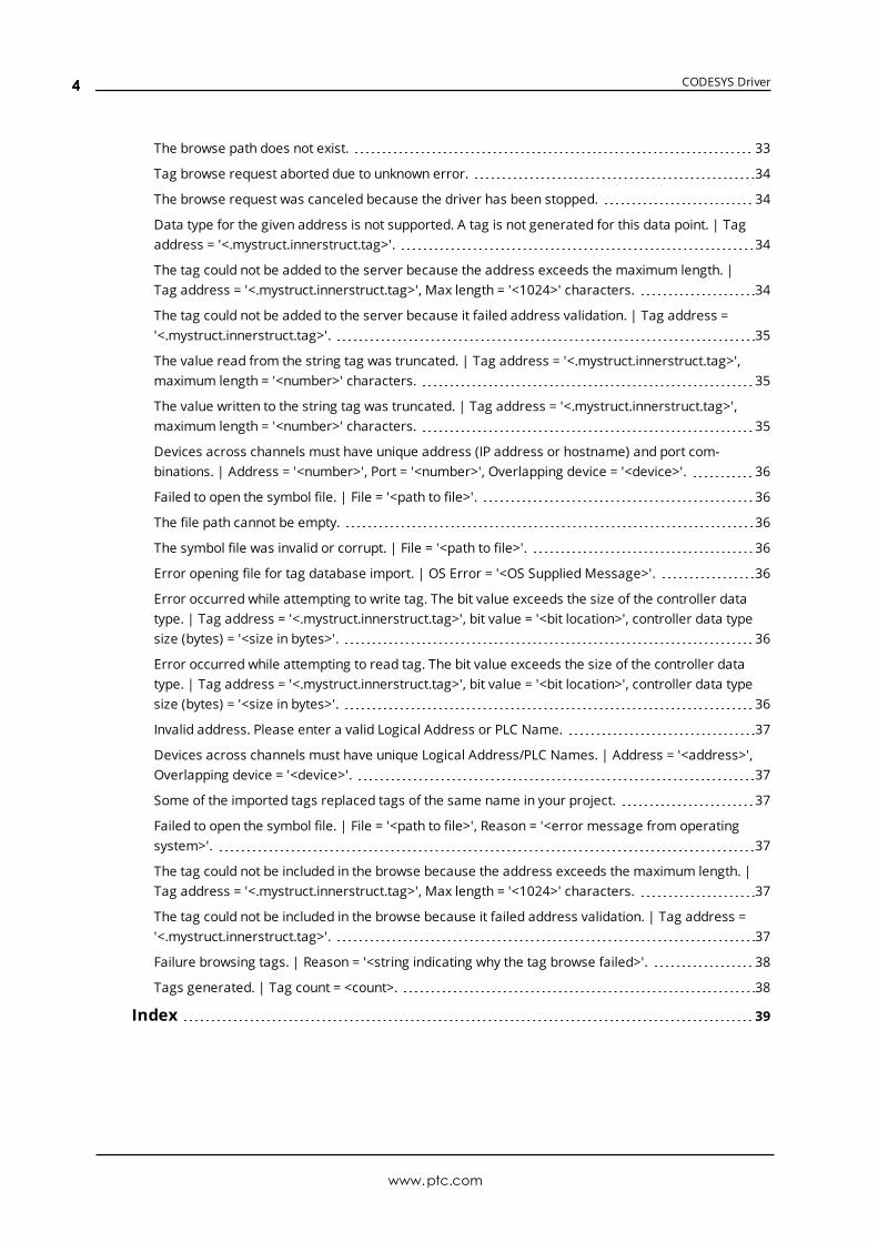
The browse path contains invalid characters. 32
Error occurred while attempting to read tag. The array size must match between the server anddevice. | Tag address = '<.mystruct.innerstruct.tag>', server array size = '<length>', device arraysize = '<length>'. 32
Error occurred while attempting to write tag. The array size must match between the server anddevice. | Tag address = '<.mystruct.innerstruct.tag>', server array size = '<length>', device arraysize = '<length>'. 32
Tag browsing failed because communications could not be established with the device. 32
Error occurred while attempting to read tag. The specified tag address has a string length that islarger than the maximum supported by the server. | Tag address = '<.mystruct.innerstruct.tag>',Max length = '<number>' characters. 33
Error occurred while attempting to write tag. The specified tag address has a string length that islarger than the maximum supported by the server. | Tag address = '<.mystruct.innerstruct.tag>',Max length = '<number>' characters. 33
www.ptc.com
3
CODESYS Driver
The browse path does not exist. 33
Tag browse request aborted due to unknown error. 34
The browse request was canceled because the driver has been stopped. 34
Data type for the given address is not supported. A tag is not generated for this data point. | Tagaddress = '<.mystruct.innerstruct.tag>'. 34
The tag could not be added to the server because the address exceeds the maximum length. |Tag address = '<.mystruct.innerstruct.tag>', Max length = '<1024>' characters. 34
The tag could not be added to the server because it failed address validation. | Tag address ='<.mystruct.innerstruct.tag>'. 35
The value read from the string tag was truncated. | Tag address = '<.mystruct.innerstruct.tag>',maximum length = '<number>' characters. 35
The value written to the string tag was truncated. | Tag address = '<.mystruct.innerstruct.tag>',maximum length = '<number>' characters. 35
Devices across channels must have unique address (IP address or hostname) and port com-binations. | Address = '<number>', Port = '<number>', Overlapping device = '<device>'. 36
Failed to open the symbol file. | File = '<path to file>'. 36
The file path cannot be empty. 36
The symbol file was invalid or corrupt. | File = '<path to file>'. 36
Error opening file for tag database import. | OS Error = '<OS Supplied Message>'. 36
Error occurred while attempting to write tag. The bit value exceeds the size of the controller datatype. | Tag address = '<.mystruct.innerstruct.tag>', bit value = '<bit location>', controller data typesize (bytes) = '<size in bytes>'. 36
Error occurred while attempting to read tag. The bit value exceeds the size of the controller datatype. | Tag address = '<.mystruct.innerstruct.tag>', bit value = '<bit location>', controller data typesize (bytes) = '<size in bytes>'. 36
Invalid address. Please enter a valid Logical Address or PLC Name. 37
Devices across channels must have unique Logical Address/PLC Names. | Address = '<address>',Overlapping device = '<device>'. 37
Some of the imported tags replaced tags of the same name in your project. 37
Failed to open the symbol file. | File = '<path to file>', Reason = '<error message from operatingsystem>'. 37
The tag could not be included in the browse because the address exceeds the maximum length. |Tag address = '<.mystruct.innerstruct.tag>', Max length = '<1024>' characters. 37
The tag could not be included in the browse because it failed address validation. | Tag address ='<.mystruct.innerstruct.tag>'. 37
Failure browsing tags. | Reason = '<string indicating why the tag browse failed>'. 38
Tags generated. | Tag count = <count>. 38
Index 39
www.ptc.com
4
CODESYS Driver
CODESYS DriverHelp version 1.041
CONTENTS
OverviewWhat is the CODESYS Driver?
Channel SetupHow do I configure channels for use with this driver?
Device SetupHow do I configure a specific device to work with this driver?
Optimizing CommunicationsHow do I get the best performance from the CODESYS Driver?
Data Types DescriptionWhat data types does this driver support?
Address DescriptionsHow do I address a data location on a CODESYS device?
OverviewThe CODESYS Driver provides a reliable way to connect CODESYS-compliant controllers to client applic-ations, including HMI, SCADA, Historian, MES, ERP, and countless custom applications.
Setup
Communication ProtocolCODESYS V2.3 Ethernet over ARTICODESYS V3 Ethernet over ARTICODESYS Gateway for V2.3CODESYS Gateway for V3
Maximum Channels and DevicesThe maximum number of channels supported by this driver is 1024. The maximum number of devices perchannel is 256.
Tag Database CreationThe Automatic Tag Database Generation feature of this driver has been designed to make setting up theOPC application less time consuming. This driver can be configured to automatically build a list of servertags within the server that correspond to device-specific data. The automatically generated OPC tags canthen be browsed from the OPC client.
Device Timeouts
www.ptc.com
5
CODESYS Driver
The driver does not support configurable timing parameters. These parameters are always set to the fol-lowing values:
l Connect Timeout: 20 seconds
l Request Timeout: 10000 milliseconds
l Retry Attempts: 3 attempts
Note: This driver doesn’t allow configuration of the request timeout. This can result in a device taking along time to update the tag quality once connectivity is lost.
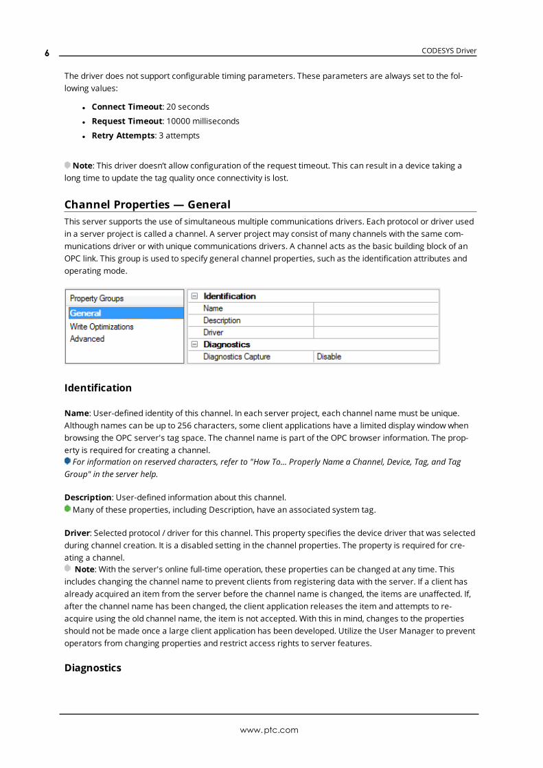
Channel Properties — GeneralThis server supports the use of simultaneous multiple communications drivers. Each protocol or driver usedin a server project is called a channel. A server project may consist of many channels with the same com-munications driver or with unique communications drivers. A channel acts as the basic building block of anOPC link. This group is used to specify general channel properties, such as the identification attributes andoperating mode.
Identification
Name: User-defined identity of this channel. In each server project, each channel name must be unique.Although names can be up to 256 characters, some client applications have a limited display window whenbrowsing the OPC server's tag space. The channel name is part of the OPC browser information. The prop-erty is required for creating a channel.For information on reserved characters, refer to "How To... Properly Name a Channel, Device, Tag, and Tag
Group" in the server help.
Description: User-defined information about this channel. Many of these properties, including Description, have an associated system tag.
Driver: Selected protocol / driver for this channel. This property specifies the device driver that was selectedduring channel creation. It is a disabled setting in the channel properties. The property is required for cre-ating a channel.
Note: With the server's online full-time operation, these properties can be changed at any time. Thisincludes changing the channel name to prevent clients from registering data with the server. If a client hasalready acquired an item from the server before the channel name is changed, the items are unaffected. If,after the channel name has been changed, the client application releases the item and attempts to re-acquire using the old channel name, the item is not accepted. With this in mind, changes to the propertiesshould not be made once a large client application has been developed. Utilize the User Manager to preventoperators from changing properties and restrict access rights to server features.
Diagnostics
www.ptc.com
6
CODESYS Driver
Diagnostics Capture: When enabled, this optionmakes the channel's diagnostic information available toOPC applications. Because the server's diagnostic features require a minimal amount of overhead pro-cessing, it is recommended that they be utilized when needed and disabled when not. The default is dis-abled.Note: This property is not available if the driver does not support diagnostics.For more information, refer to "Communication Diagnostics" and "Statistics Tags" in the server help.
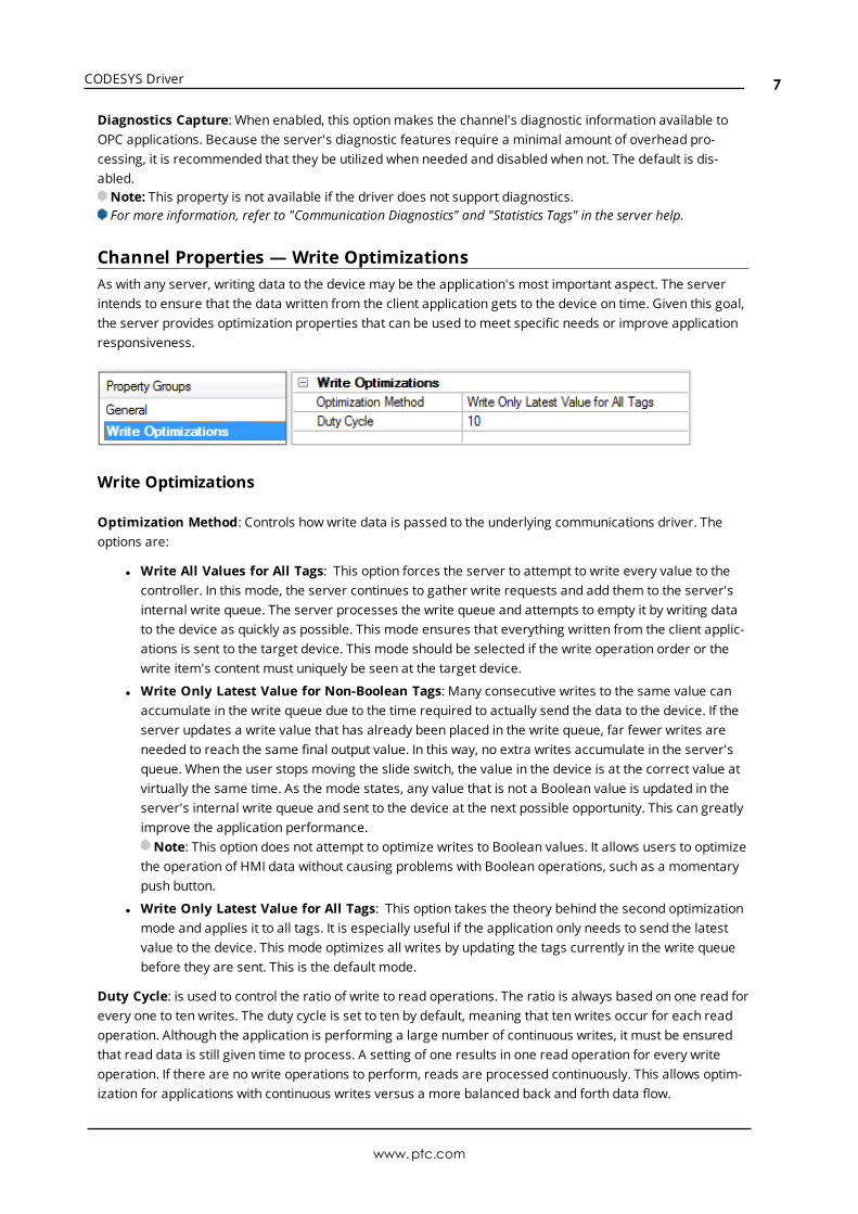
Channel Properties — Write OptimizationsAs with any server, writing data to the device may be the application's most important aspect. The serverintends to ensure that the data written from the client application gets to the device on time. Given this goal,the server provides optimization properties that can be used to meet specific needs or improve applicationresponsiveness.
Write Optimizations
Optimization Method: Controls how write data is passed to the underlying communications driver. Theoptions are:
l Write All Values for All Tags: This option forces the server to attempt to write every value to thecontroller. In this mode, the server continues to gather write requests and add them to the server'sinternal write queue. The server processes the write queue and attempts to empty it by writing datato the device as quickly as possible. This mode ensures that everything written from the client applic-ations is sent to the target device. This mode should be selected if the write operation order or thewrite item's content must uniquely be seen at the target device.
l Write Only Latest Value for Non-Boolean Tags: Many consecutive writes to the same value canaccumulate in the write queue due to the time required to actually send the data to the device. If theserver updates a write value that has already been placed in the write queue, far fewer writes areneeded to reach the same final output value. In this way, no extra writes accumulate in the server'squeue. When the user stops moving the slide switch, the value in the device is at the correct value atvirtually the same time. As the mode states, any value that is not a Boolean value is updated in theserver's internal write queue and sent to the device at the next possible opportunity. This can greatlyimprove the application performance.Note: This option does not attempt to optimize writes to Boolean values. It allows users to optimize
the operation of HMI data without causing problems with Boolean operations, such as a momentarypush button.
l Write Only Latest Value for All Tags: This option takes the theory behind the second optimizationmode and applies it to all tags. It is especially useful if the application only needs to send the latestvalue to the device. This mode optimizes all writes by updating the tags currently in the write queuebefore they are sent. This is the default mode.
Duty Cycle: is used to control the ratio of write to read operations. The ratio is always based on one read forevery one to ten writes. The duty cycle is set to ten by default, meaning that ten writes occur for each readoperation. Although the application is performing a large number of continuous writes, it must be ensuredthat read data is still given time to process. A setting of one results in one read operation for every writeoperation. If there are no write operations to perform, reads are processed continuously. This allows optim-ization for applications with continuous writes versus a more balanced back and forth data flow.
www.ptc.com
7
CODESYS Driver
Note: It is recommended that the application be characterized for compatibility with the write optimizationenhancements before being used in a production environment.
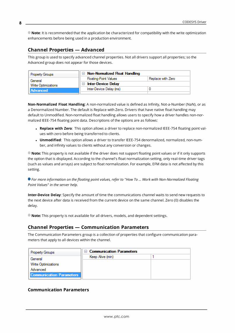
Channel Properties — AdvancedThis group is used to specify advanced channel properties. Not all drivers support all properties; so theAdvanced group does not appear for those devices.
Non-Normalized Float Handling: A non-normalized value is defined as Infinity, Not-a-Number (NaN), or asa Denormalized Number. The default is Replace with Zero. Drivers that have native float handling maydefault to Unmodified. Non-normalized float handling allows users to specify how a driver handles non-nor-malized IEEE-754 floating point data. Descriptions of the options are as follows:
l Replace with Zero: This option allows a driver to replace non-normalized IEEE-754 floating point val-ues with zero before being transferred to clients.
l Unmodified: This option allows a driver to transfer IEEE-754 denormalized, normalized, non-num-ber, and infinity values to clients without any conversion or changes.
Note: This property is not available if the driver does not support floating point values or if it only supportsthe option that is displayed. According to the channel's float normalization setting, only real-time driver tags(such as values and arrays) are subject to float normalization. For example, EFM data is not affected by thissetting.
For more information on the floating point values, refer to "How To ... Work with Non-Normalized FloatingPoint Values" in the server help.
Inter-Device Delay: Specify the amount of time the communications channel waits to send new requests tothe next device after data is received from the current device on the same channel. Zero (0) disables thedelay.
Note: This property is not available for all drivers, models, and dependent settings.
Channel Properties — Communication ParametersThe Communication Parameters group is a collection of properties that configure communication para-meters that apply to all devices within the channel.
Communication Parameters
www.ptc.com
8
CODESYS Driver
Keep Alive: Configure howmany minutes the driver maintain an open connection with the device after all cli-ent references are removed. If no client references are added before the timeout expires, the connection isclosed. If a client reference is added while the timer is active, the timeout is canceled, preventing the con-nection from being closed.
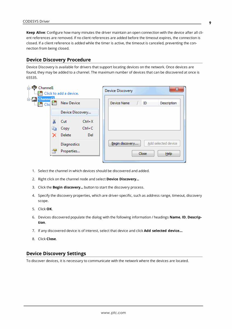
Device Discovery ProcedureDevice Discovery is available for drivers that support locating devices on the network. Once devices arefound, they may be added to a channel. The maximum number of devices that can be discovered at once is65535.
1. Select the channel in which devices should be discovered and added.
2. Right click on the channel node and select Device Discovery...
3. Click the Begin discovery... button to start the discovery process.
4. Specify the discovery properties, which are driver-specific, such as address range, timeout, discoveryscope.
5. ClickOK.
6. Devices discovered populate the dialog with the following information / headings Name, ID, Descrip-tion.
7. If any discovered device is of interest, select that device and click Add selected device....
8. Click Close.
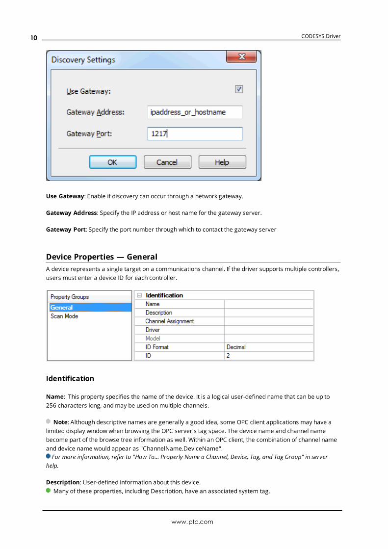
Device Discovery SettingsTo discover devices, it is necessary to communicate with the network where the devices are located.
www.ptc.com
9
CODESYS Driver
Use Gateway: Enable if discovery can occur through a network gateway.
Gateway Address: Specify the IP address or host name for the gateway server.
Gateway Port: Specify the port number through which to contact the gateway server
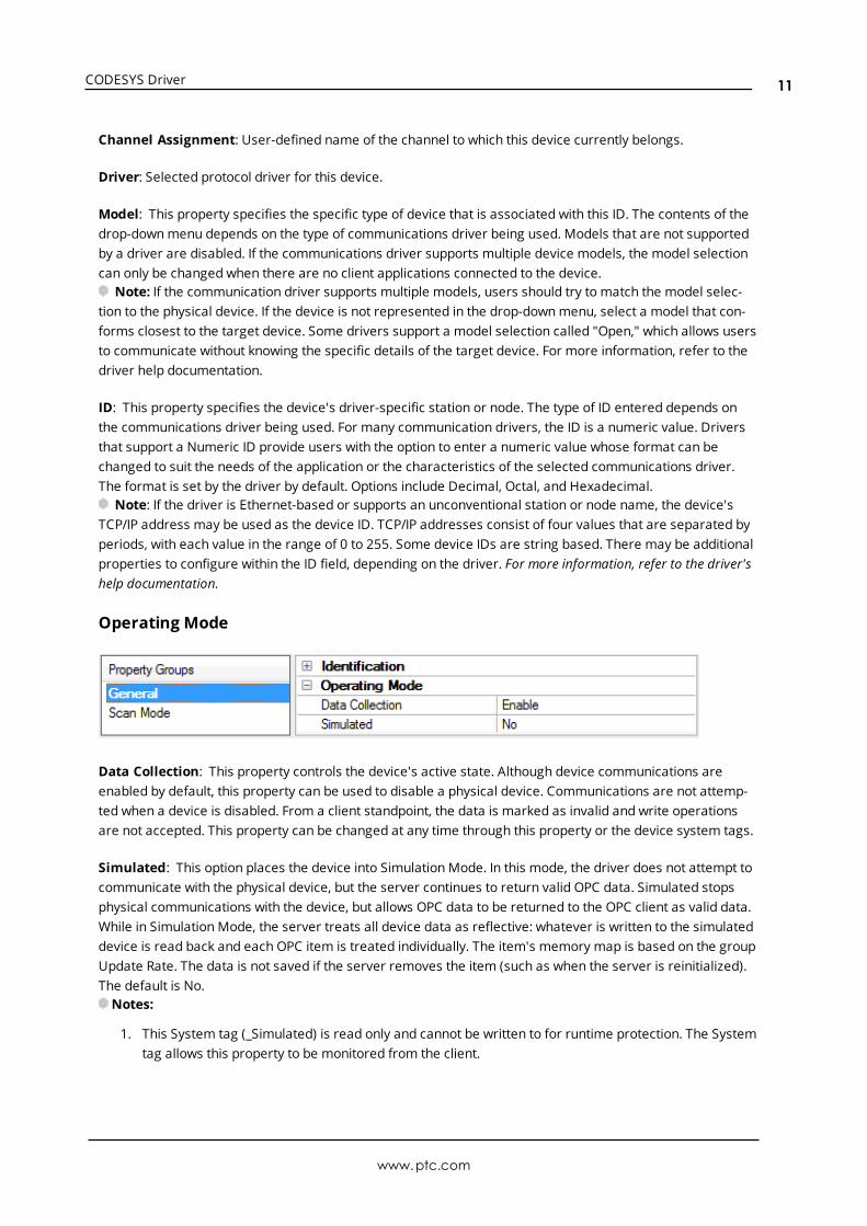
Device Properties — GeneralA device represents a single target on a communications channel. If the driver supports multiple controllers,users must enter a device ID for each controller.
Identification
Name: This property specifies the name of the device. It is a logical user-defined name that can be up to256 characters long, andmay be used onmultiple channels.
Note: Although descriptive names are generally a good idea, some OPC client applications may have alimited display window when browsing the OPC server's tag space. The device name and channel namebecome part of the browse tree information as well. Within an OPC client, the combination of channel nameand device name would appear as "ChannelName.DeviceName".For more information, refer to "How To... Properly Name a Channel, Device, Tag, and Tag Group" in server
help.
Description: User-defined information about this device.Many of these properties, including Description, have an associated system tag.
www.ptc.com
10
CODESYS Driver
Channel Assignment: User-defined name of the channel to which this device currently belongs.
Driver: Selected protocol driver for this device.
Model: This property specifies the specific type of device that is associated with this ID. The contents of thedrop-downmenu depends on the type of communications driver being used. Models that are not supportedby a driver are disabled. If the communications driver supports multiple device models, the model selectioncan only be changed when there are no client applications connected to the device.
Note: If the communication driver supports multiple models, users should try to match the model selec-tion to the physical device. If the device is not represented in the drop-downmenu, select a model that con-forms closest to the target device. Some drivers support a model selection called "Open," which allows usersto communicate without knowing the specific details of the target device. For more information, refer to thedriver help documentation.
ID: This property specifies the device's driver-specific station or node. The type of ID entered depends onthe communications driver being used. For many communication drivers, the ID is a numeric value. Driversthat support a Numeric ID provide users with the option to enter a numeric value whose format can bechanged to suit the needs of the application or the characteristics of the selected communications driver.The format is set by the driver by default. Options include Decimal, Octal, and Hexadecimal.
Note: If the driver is Ethernet-based or supports an unconventional station or node name, the device'sTCP/IP address may be used as the device ID. TCP/IP addresses consist of four values that are separated byperiods, with each value in the range of 0 to 255. Some device IDs are string based. There may be additionalproperties to configure within the ID field, depending on the driver. For more information, refer to the driver'shelp documentation.
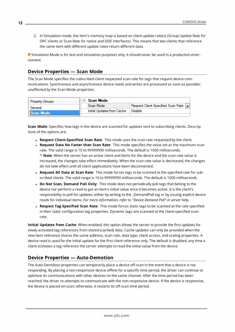
Operating Mode
Data Collection: This property controls the device's active state. Although device communications areenabled by default, this property can be used to disable a physical device. Communications are not attemp-ted when a device is disabled. From a client standpoint, the data is marked as invalid and write operationsare not accepted. This property can be changed at any time through this property or the device system tags.
Simulated: This option places the device into Simulation Mode. In this mode, the driver does not attempt tocommunicate with the physical device, but the server continues to return valid OPC data. Simulated stopsphysical communications with the device, but allows OPC data to be returned to the OPC client as valid data.While in Simulation Mode, the server treats all device data as reflective: whatever is written to the simulateddevice is read back and each OPC item is treated individually. The item's memory map is based on the groupUpdate Rate. The data is not saved if the server removes the item (such as when the server is reinitialized).The default is No.Notes:
1. This System tag (_Simulated) is read only and cannot be written to for runtime protection. The Systemtag allows this property to be monitored from the client.
www.ptc.com
11
CODESYS Driver
2. In Simulationmode, the item's memory map is based on client update rate(s) (Group Update Rate forOPC clients or Scan Rate for native and DDE interfaces). This means that two clients that referencethe same item with different update rates return different data.
Simulation Mode is for test and simulation purposes only. It should never be used in a production envir-onment.
Device Properties — Scan ModeThe ScanMode specifies the subscribed-client requested scan rate for tags that require device com-munications. Synchronous and asynchronous device reads and writes are processed as soon as possible;unaffected by the ScanMode properties.
Scan Mode: Specifies how tags in the device are scanned for updates sent to subscribing clients. Descrip-tions of the options are:
l Respect Client-Specified Scan Rate: This mode uses the scan rate requested by the client.l Request Data No Faster than Scan Rate: This mode specifies the value set as the maximum scan
rate. The valid range is 10 to 99999990 milliseconds. The default is 1000 milliseconds.Note: When the server has an active client and items for the device and the scan rate value is
increased, the changes take effect immediately. When the scan rate value is decreased, the changesdo not take effect until all client applications have been disconnected.
l Request All Data at Scan Rate: This mode forces tags to be scanned at the specified rate for sub-scribed clients. The valid range is 10 to 99999990 milliseconds. The default is 1000 milliseconds.
l Do Not Scan, Demand Poll Only: This mode does not periodically poll tags that belong to thedevice nor perform a read to get an item's initial value once it becomes active. It is the client'sresponsibility to poll for updates, either by writing to the _DemandPoll tag or by issuing explicit devicereads for individual items. For more information, refer to "Device Demand Poll" in server help.
l Respect Tag-Specified Scan Rate: This mode forces static tags to be scanned at the rate specifiedin their static configuration tag properties. Dynamic tags are scanned at the client-specified scanrate.
Initial Updates from Cache: When enabled, this option allows the server to provide the first updates fornewly activated tag references from stored (cached) data. Cache updates can only be provided when thenew item reference shares the same address, scan rate, data type, client access, and scaling properties. Adevice read is used for the initial update for the first client reference only. The default is disabled; any time aclient activates a tag reference the server attempts to read the initial value from the device.
Device Properties — Auto-DemotionThe Auto-Demotion properties can temporarily place a device off-scan in the event that a device is notresponding. By placing a non-responsive device offline for a specific time period, the driver can continue tooptimize its communications with other devices on the same channel. After the time period has beenreached, the driver re-attempts to communicate with the non-responsive device. If the device is responsive,the device is placed on-scan; otherwise, it restarts its off-scan time period.
www.ptc.com
12
CODESYS Driver
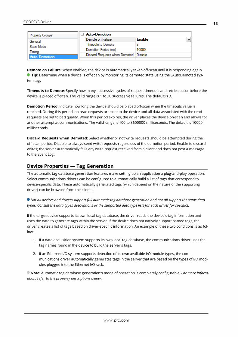
Demote on Failure: When enabled, the device is automatically taken off-scan until it is responding again.Tip: Determine when a device is off-scan by monitoring its demoted state using the _AutoDemoted sys-
tem tag.
Timeouts to Demote: Specify howmany successive cycles of request timeouts and retries occur before thedevice is placed off-scan. The valid range is 1 to 30 successive failures. The default is 3.
Demotion Period: Indicate how long the device should be placed off-scan when the timeouts value isreached. During this period, no read requests are sent to the device and all data associated with the readrequests are set to bad quality. When this period expires, the driver places the device on-scan and allows foranother attempt at communications. The valid range is 100 to 3600000 milliseconds. The default is 10000milliseconds.
Discard Requests when Demoted: Select whether or not write requests should be attempted during theoff-scan period. Disable to always send write requests regardless of the demotion period. Enable to discardwrites; the server automatically fails any write request received from a client and does not post a messageto the Event Log.
Device Properties — Tag GenerationThe automatic tag database generation features make setting up an application a plug-and-play operation.Select communications drivers can be configured to automatically build a list of tags that correspond todevice-specific data. These automatically generated tags (which depend on the nature of the supportingdriver) can be browsed from the clients.
Not all devices and drivers support full automatic tag database generation and not all support the same datatypes. Consult the data types descriptions or the supported data type lists for each driver for specifics.
If the target device supports its own local tag database, the driver reads the device's tag information anduses the data to generate tags within the server. If the device does not natively support named tags, thedriver creates a list of tags based on driver-specific information. An example of these two conditions is as fol-lows:
1. If a data acquisition system supports its own local tag database, the communications driver uses thetag names found in the device to build the server's tags.
2. If an Ethernet I/O system supports detection of its own available I/Omodule types, the com-munications driver automatically generates tags in the server that are based on the types of I/Omod-ules plugged into the Ethernet I/O rack.
Note: Automatic tag database generation's mode of operation is completely configurable. For more inform-ation, refer to the property descriptions below.
www.ptc.com
13
CODESYS Driver
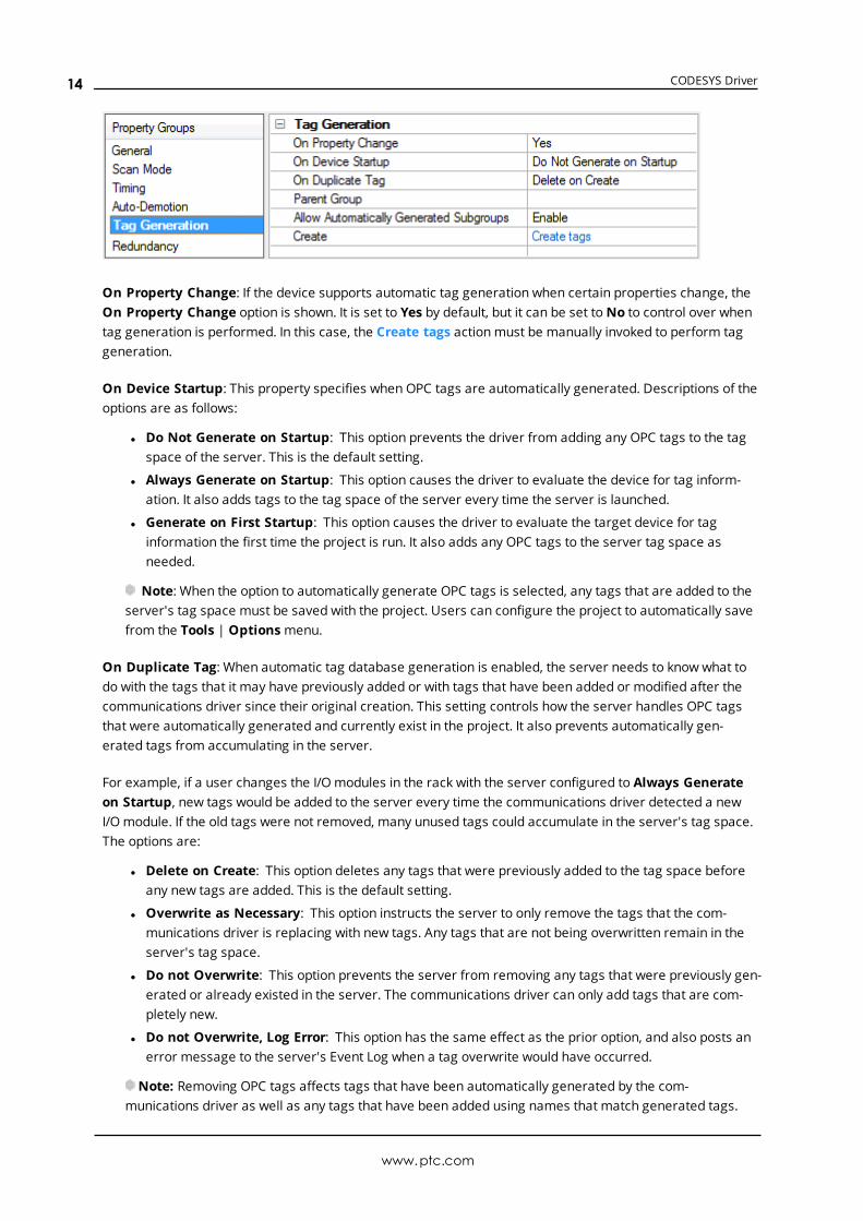
On Property Change: If the device supports automatic tag generation when certain properties change, theOn Property Change option is shown. It is set to Yes by default, but it can be set toNo to control over whentag generation is performed. In this case, the Create tags actionmust be manually invoked to perform taggeneration.
On Device Startup: This property specifies when OPC tags are automatically generated. Descriptions of theoptions are as follows:
l Do Not Generate on Startup: This option prevents the driver from adding any OPC tags to the tagspace of the server. This is the default setting.
l Always Generate on Startup: This option causes the driver to evaluate the device for tag inform-ation. It also adds tags to the tag space of the server every time the server is launched.
l Generate on First Startup: This option causes the driver to evaluate the target device for taginformation the first time the project is run. It also adds any OPC tags to the server tag space asneeded.
Note: When the option to automatically generate OPC tags is selected, any tags that are added to theserver's tag space must be saved with the project. Users can configure the project to automatically savefrom the Tools | Optionsmenu.
On Duplicate Tag: When automatic tag database generation is enabled, the server needs to know what todo with the tags that it may have previously added or with tags that have been added or modified after thecommunications driver since their original creation. This setting controls how the server handles OPC tagsthat were automatically generated and currently exist in the project. It also prevents automatically gen-erated tags from accumulating in the server.
For example, if a user changes the I/Omodules in the rack with the server configured to Always Generateon Startup, new tags would be added to the server every time the communications driver detected a newI/Omodule. If the old tags were not removed, many unused tags could accumulate in the server's tag space.The options are:
l Delete on Create: This option deletes any tags that were previously added to the tag space beforeany new tags are added. This is the default setting.
l Overwrite as Necessary: This option instructs the server to only remove the tags that the com-munications driver is replacing with new tags. Any tags that are not being overwritten remain in theserver's tag space.
l Do not Overwrite: This option prevents the server from removing any tags that were previously gen-erated or already existed in the server. The communications driver can only add tags that are com-pletely new.
l Do not Overwrite, Log Error: This option has the same effect as the prior option, and also posts anerror message to the server's Event Log when a tag overwrite would have occurred.
Note: Removing OPC tags affects tags that have been automatically generated by the com-munications driver as well as any tags that have been added using names that match generated tags.
www.ptc.com
14
CODESYS Driver
Users should avoid adding tags to the server using names that may match tags that are automaticallygenerated by the driver.
Parent Group: This property keeps automatically generated tags frommixing with tags that have beenenteredmanually by specifying a group to be used for automatically generated tags. The name of the groupcan be up to 256 characters. This parent group provides a root branch to which all automatically generatedtags are added.
Allow Automatically Generated Subgroups: This property controls whether the server automatically cre-ates subgroups for the automatically generated tags. This is the default setting. If disabled, the server gen-erates the device's tags in a flat list without any grouping. In the server project, the resulting tags are namedwith the address value. For example, the tag names are not retained during the generation process.
Note: If, as the server is generating tags, a tag is assigned the same name as an existing tag, the systemautomatically increments to the next highest number so that the tag name is not duplicated. For example, ifthe generation process creates a tag named "AI22" that already exists, it creates the tag as "AI23" instead.
Create: Initiates the creation of automatically generated OPC tags. If the device's configuration has beenmodified, Create tags forces the driver to reevaluate the device for possible tag changes. Its ability to beaccessed from the System tags allows a client application to initiate tag database creation.
Note: Create tags is disabled if the Configuration edits a project offline.
Automatic Tag Database Generation
l When tags are automatically generated, they are created with Client Access privileges matching theaccess privileges provided by the PLC wherever possible.
l Tags with Write Only privileges are generated with Read/Write Client Access privileges because thereis no Write Only Client Access setting in the server.
l Tags that do not have Read or Write permissions are not generated as there is no correspondingaccess privilege in the server.
l According to the CODESYS V2.3 Protocol, addresses must be defined in a PLC Program variable list ora Global variable list. The first group is always the location of the variable (Global or the name of PLCProgram where the tag is defined).
l Arrays are always expanded during tag generation, meaning that a tag is created for each element inthe array. No tag is generated for the array itself.
l When Allow Automatically Generated Subgroups is enabled, subgroups are created for each seg-ment of a tag address, with a maximum depth of eight groups. The tag name is the part of theaddress left over after subgroups have been created.
l When array elements are generated, provided the nested group limit has not been reached, the tagsare placed in a group named after the array to which they belong.
CODESYS V2.3 Examples
Tag Address Groups Tag Name
.myTag Global myTag
PLC_PRG.myTag PLC_PRG myTag
.myStruct.myArray[0] Global.myStruct.myArray[x] myArray[0]
PLC_PRG.myStruct.myArray[0] PLC_PRG.myStruct.myArray[x] myArray[0]
.group1…group7.myTag Global.group1…group7 Group7_myTag
CODESYS V3 Examples
www.ptc.com
15
CODESYS Driver
Tag Address Groups Tag Name
Application.GVL.myTag Application.GVL myTag
Application.PLC_PRG.myTag Application.PLC_PRG myTag
Application.GVL.myStruct.myArray[0]Application.GVL.myStruct.myArray[x]
myArray[0]
Application.PLC_PRG.myStruct.myArray[0]
Application.PLC_PRG.myStruct.myArray[x]
myArray[0]
Application.GVL.group1…group6.myTag Application.GVL.group1…group6 Group6_myTag
Tip: To make it easier to read, Groups have been concatenated together using periods (similar to how auser would access the tag via an OPC DA/UA client).
See Also: Tag Import Settings
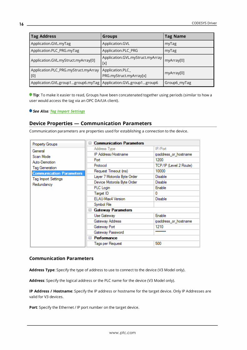
Device Properties — Communication ParametersCommunication parameters are properties used for establishing a connection to the device.
Communication Parameters
Address Type: Specify the type of address to use to connect to the device (V3 Model only).
Address: Specify the logical address or the PLC name for the device (V3 Model only).
IP Address / Hostname: Specify the IP address or hostname for the target device. Only IP Addresses arevalid for V3 devices.
Port: Specify the Ethernet / IP port number on the target device.
www.ptc.com
16
CODESYS Driver
Protocol: Specify the protocol in use in this device.
Request Timeout: Specify how long the driver waits for a response from the target device to complete. Thevalid range is 4,000 to 9,999,999 milliseconds (167.6667 minutes). The default is 10,000 milliseconds. Validfor V2.3 Model only.
Layer 7 Motorola Byte Order: Specify if Layer 7 uses the Motorola byte order (Big Endian).
Device Motorola Byte Order: Specify if the target device uses the Motorola byte order (Big Endian). In mostcases, this is set to the same value as Layer 7 Motorola Byte Order.
PLC Login: Specify if the driver should stay logged into the PLC after connecting. This setting should be dis-abled if the PLC only supports a single client connection, otherwise it should be enabled.
Target ID: Specify the identity if this is a sub-PLC device. PLCs that require communications to be routedthrough another PLC are called sub-PLCs. The target ID provides additional address information required tocommunicate with sub-PLCs. When not communicating with a sub-PLC, this setting should be 0.
ELAU-Max4 Version: Specify the hardware revision of the target PLC. This value should be disabled exceptwhen the device is an ELAU Max 4 1100 or 1200.
Symbol File: Specify the full file name, including path, to use if the symbol file cannot be stored on thedevice. This symbol file must match the symbols stored on the device. If the symbols do not match, com-munications with the device fails. This may be left blank if the symbol file is stored on the device. V3 devicesstore the symbol file on the device, so this property is not required.
The IP address and port combinationmust be unique across all devices, even under different channels.Most CODESYS PLCs do not support parallel communication channels, so there is no performance gain bypointing multiple channels at the same CODESYS PLC. Currently, copying and pasting a channel in the servercreates a device with the same IP address and port combination. All devices under the channel that havebeen copied should be changed to remove any IP address and port combination overlaps. Undefined beha-vior may occur if these collisions are not resolved.
Gateway Parameters
Use Gateway: Specify if a gateway should be used when connecting to the device.
Gateway Address: Specify the IP address or hostname for the gateway.
Gateway Port: Specify the port for the gateway.
Gateway Password: Specify the password for the gateway (V2.3 Model only).
Device connection via a gateway requires that the CODESYS Gateway be installed on the same host as theserver. If the CODESYS Gateway is not installed on the same server as the host, reading a tag results in a“Device is not responding” message in the event log. This only applies to configurations including the V2.3Ethernet model.
Device connection via a gateway requires that initial communications be serialized. If devices are con-figured under different channels, they connect to the gateway one at a time. After the initial connection, com-munications stop being serialized. This only applies to configurations including the V2.3 Ethernet model.
www.ptc.com
17
CODESYS Driver
Performance
Tags per Request: Maximum number of tags to include in a single request. For each single request, there issome service overhead. In general, it is better to handle several items in one request instead of requesteach item separately. However, requesting many items in one request causes the round-trip time (answertime) to rise. Depending on the application, it may be better to split up huge lists in several small requests.
Note: The number of writes per request is limited based on the Duty Cycle specified in the channel set-tings.
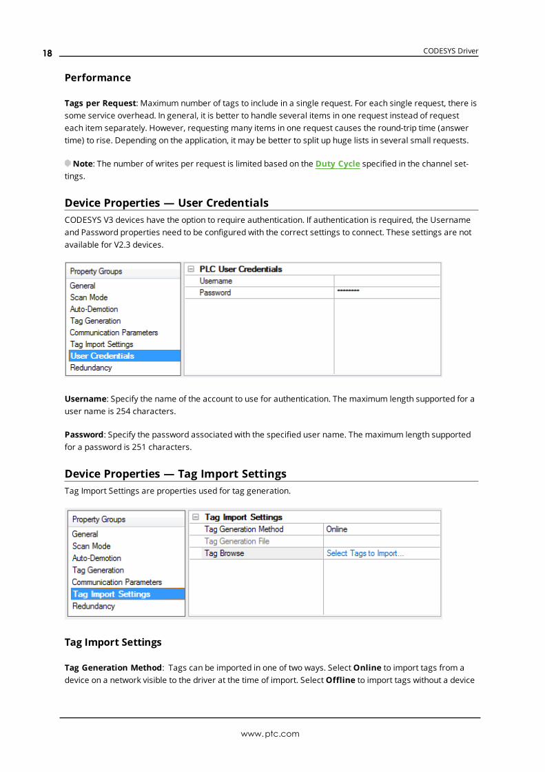
Device Properties — User CredentialsCODESYS V3 devices have the option to require authentication. If authentication is required, the Usernameand Password properties need to be configured with the correct settings to connect. These settings are notavailable for V2.3 devices.
Username: Specify the name of the account to use for authentication. The maximum length supported for auser name is 254 characters.
Password: Specify the password associated with the specified user name. The maximum length supportedfor a password is 251 characters.
Device Properties — Tag Import SettingsTag Import Settings are properties used for tag generation.
Tag Import Settings
Tag Generation Method: Tags can be imported in one of two ways. SelectOnline to import tags from adevice on a network visible to the driver at the time of import. SelectOffline to import tags without a device
www.ptc.com
18
CODESYS Driver
connection by providing the server with the corresponding plain-text symbol (.SYM) file created when theCODESYS project is compiled.
Tag Generation File: Specify the path and file name of a symbol file to import. To locate and select the .SYMfile, click on the Browse (...) button. This property is disabled if Online is chosen as the import method.Tip: Once the file is selected, start tag generation using the Create Tags command in the Tag Generation
group.
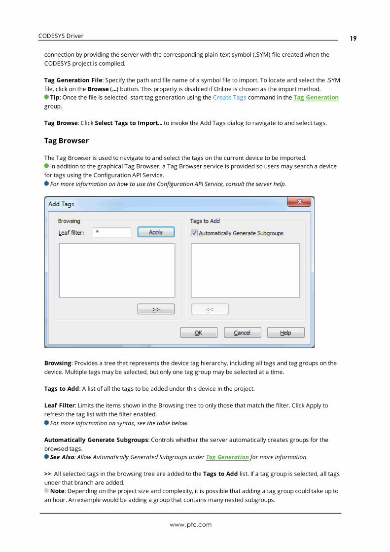
Tag Browse: Click Select Tags to Import... to invoke the Add Tags dialog to navigate to and select tags.
Tag Browser
The Tag Browser is used to navigate to and select the tags on the current device to be imported.In addition to the graphical Tag Browser, a Tag Browser service is provided so users may search a device
for tags using the Configuration API Service.For more information on how to use the Configuration API Service, consult the server help.
Browsing: Provides a tree that represents the device tag hierarchy, including all tags and tag groups on thedevice. Multiple tags may be selected, but only one tag groupmay be selected at a time.
Tags to Add: A list of all the tags to be added under this device in the project.
Leaf Filter: Limits the items shown in the Browsing tree to only those that match the filter. Click Apply torefresh the tag list with the filter enabled.For more information on syntax, see the table below.
Automatically Generate Subgroups: Controls whether the server automatically creates groups for thebrowsed tags.See Also: Allow Automatically Generated Subgroups under Tag Generation for more information.
>>: All selected tags in the browsing tree are added to the Tags to Add list. If a tag group is selected, all tagsunder that branch are added.Note: Depending on the project size and complexity, it is possible that adding a tag group could take up to
an hour. An example would be adding a group that contains many nested subgroups.
www.ptc.com
19
CODESYS Driver
<<: Removes all selected tags from the Tags to Add list.
Note: The user must have permission to add tags, delete tags, and to add tag groups to use the TagBrowser.
Filter Syntax
The filter allows the browser to reduce the items displayed to those which match a pattern. The filter onlysupports ASCII characters. The syntax supported is documented in the table below.
Characters inPattern
Matches in String
?
Any single character
Example: ? matches “a”, “!”, “3”, etc. It does not match “aa” or “ok” as those stringshave two characters versus one.
*
Zero or more characters
Example: *server matches “server”, “cloud server”, and “OPC server” ...not “OPCServer” or “erver”.
#Any single digit (0-9)
Example: # matches “0”, “1”, “2”; not “a” or “z”.
[charlist]
Any single character in the list.
Example: [a-c] matches “a”, “b”, or “c”; not any other characters including “A” “B” and“C”.
[!charlist]Any single character not in the list.
Example: [!a-c] matches “d”, “e”, “A”, and “B”; not “a”, “b”, or “c”.
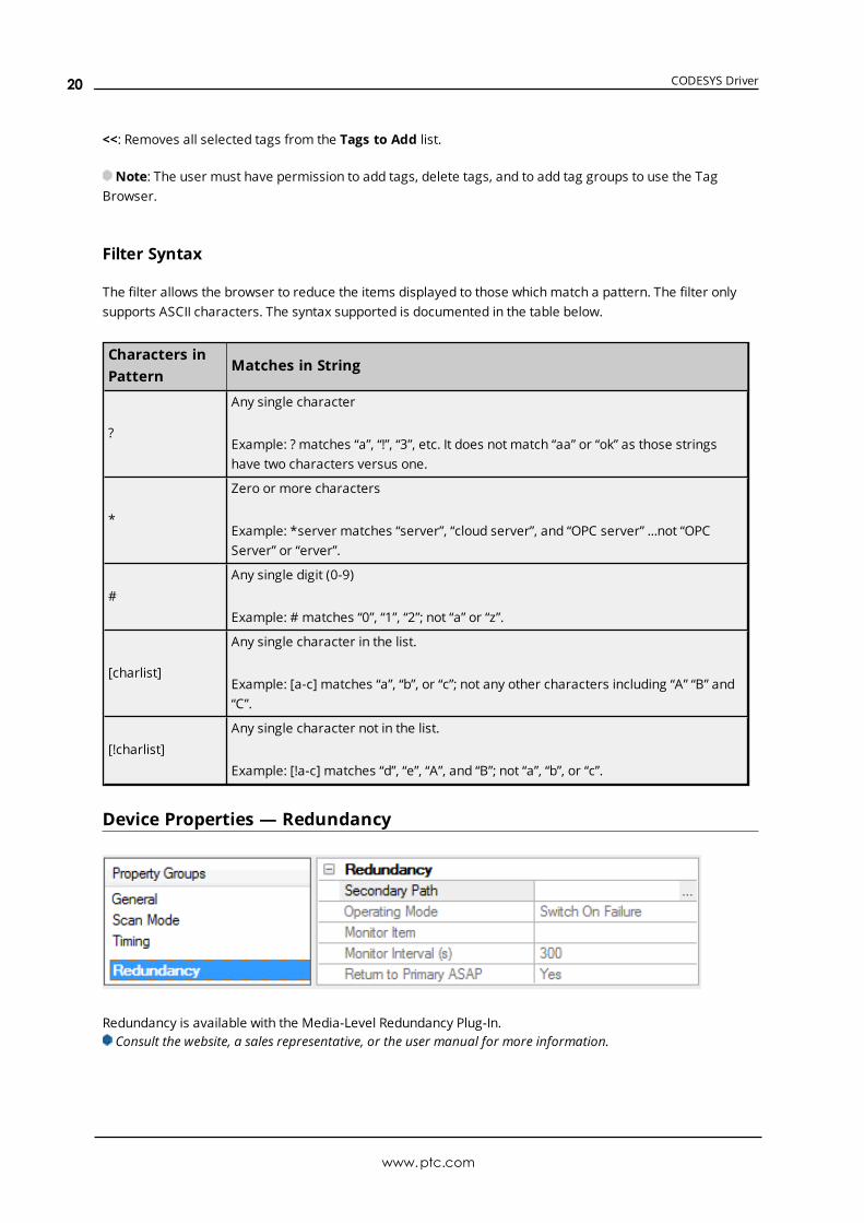
Device Properties — Redundancy
Redundancy is available with the Media-Level Redundancy Plug-In.Consult the website, a sales representative, or the user manual for more information.
www.ptc.com
20
CODESYS Driver
Performance Optimization
Optimizing CommunicationsWith any programmable controller, there are unique ways for optimizing system throughput, and theCODESYS Driver is no different. The CODESYS Driver is designed to optimize reads and writes. For tags of alldata types, requests are grouped into a single transaction. This provides drastic improvement in per-formance over single-tag transactions. The only limitation is on the number of tags that can fit in a singletransaction.
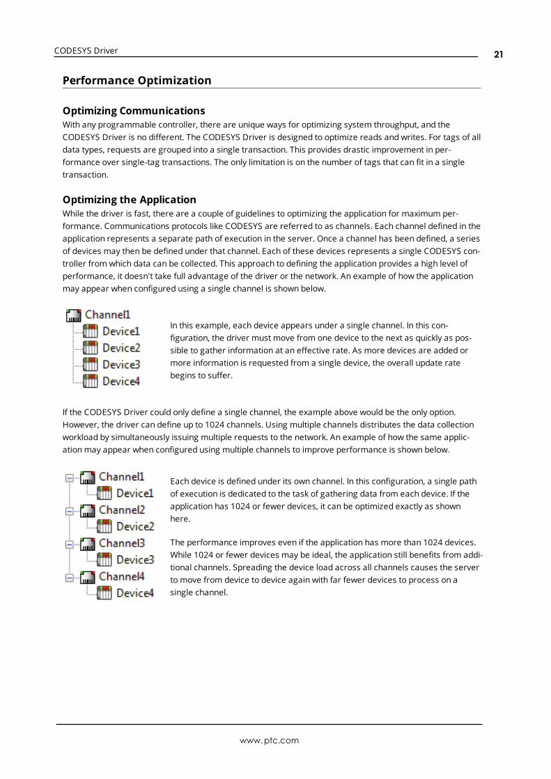
Optimizing the ApplicationWhile the driver is fast, there are a couple of guidelines to optimizing the application for maximum per-formance. Communications protocols like CODESYS are referred to as channels. Each channel defined in theapplication represents a separate path of execution in the server. Once a channel has been defined, a seriesof devices may then be defined under that channel. Each of these devices represents a single CODESYS con-troller from which data can be collected. This approach to defining the application provides a high level ofperformance, it doesn't take full advantage of the driver or the network. An example of how the applicationmay appear when configured using a single channel is shown below.
In this example, each device appears under a single channel. In this con-figuration, the driver must move from one device to the next as quickly as pos-sible to gather information at an effective rate. As more devices are added ormore information is requested from a single device, the overall update ratebegins to suffer.
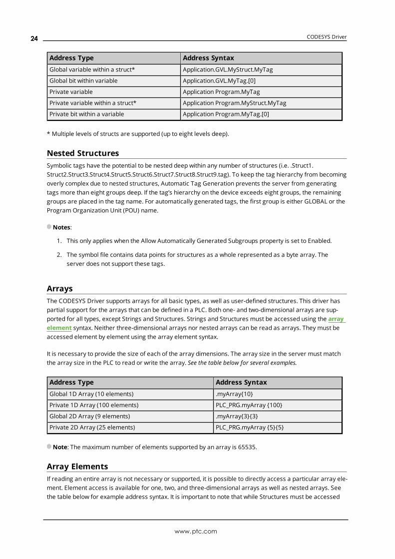
If the CODESYS Driver could only define a single channel, the example above would be the only option.However, the driver can define up to 1024 channels. Using multiple channels distributes the data collectionworkload by simultaneously issuing multiple requests to the network. An example of how the same applic-ationmay appear when configured using multiple channels to improve performance is shown below.
Each device is defined under its own channel. In this configuration, a single pathof execution is dedicated to the task of gathering data from each device. If theapplication has 1024 or fewer devices, it can be optimized exactly as shownhere.
The performance improves even if the application has more than 1024 devices.While 1024 or fewer devices may be ideal, the application still benefits from addi-tional channels. Spreading the device load across all channels causes the serverto move from device to device again with far fewer devices to process on asingle channel.
www.ptc.com
21
CODESYS Driver
Data Types Description
Data Type Description
Boolean Single bit
Byte Unsigned 8-bit value
Char Signed 8-bit value
Word Unsigned 16-bit value
Short Signed 16-bit value
DWord Unsigned 32-bit value
Long Signed 32-bit value
QWord Unsigned 64-bit value
Long Long Signed 64-bit value
Float 32-bit IEEE floating point value
Double 64-bit IEEE floating point value
Date 64-bit IEEE date and time value
String Null-terminated character array
For a description of CODESYS-platform specific data types, refer to CODESYS data types.
Unsupported Data TypesUnsupported data types include LBCD and BCD.
See Also: Address Descriptions, Atomic Data Types
Symbolic Tag-Based AddressingThe CODESYS Driver uses a symbolic addressing structure for tags. These tags (commonly referred to asNative Tags) differ from conventional PLC data items in that the tag name itself is the address, not a physicalor logical address.
Client / Server Tag Address RulesCODESYS variable names correspond to client / server tag addresses. CODESYS variable names (enteredvia CODESYS PLC) follow the IEC 61131-3 identifier rules. Client / server tag addresses follow these samerules and are listed below:
l Must begin with an alphabetic (A-Z, a-z) character or an underscore (_).
l Can only contain alphanumeric characters and underscores.
l Are not case sensitive.
Client / Server Tag Name RulesThe rules for tag name assignment in the server differs from address assignment because tag names can-not begin with an underscore.
Tag ScopeGlobal Tags
www.ptc.com
22
CODESYS Driver
Global tags are CODESYS variables that have global scope in the controller. Any program or task can accessthe global tags, which use the following notation:
.<tag name>
.<struct name>.<tag name>
Note: Structures can be nested within other structures, so a tag name may be prefixed by multiple struc-ture entries (<outer struct>.<inner struct>.<my tag>).
Program TagsProgram tags are identical to global tags, except that a program tag's scope is local to the program in whichit is defined. Program tags have the same addressing rules and limitations as global tags. The only dif-ference is that program tags are prefixed with the program name:<program name>.<tag name>OR<program name>.<outer struct>.<inner struct>.<tag name>
Example:“prog_1.tag_1”: Program “prog_1” containing a tag called “tag_1”
Tag Addressing
CODESYS V2.3
There are two categories of variables supported by CODESYS: global and private. Each of these categorieshas a slightly different format. The following tables provides examples of the different CODESYS variablesand their corresponding server addressing syntax.
Address Type Address Syntax
Global variable .MyTag
Global variable within a struct* .MyStruct.MyTag
Global bit within variable .MyTag.[0]
Private variable Program.MyTag
Private variable within a struct* Program.MyStruct.MyTag
Private bit within a variable Program.MyTag.[0]
* Multiple levels of structs are supported (up to eight levels deep).
CODESYS V3
There are two categories of variables supported by CODESYS: global and private. Each of these categorieshas a slightly different format. The following tables provides examples of the different CODESYS variablesand their corresponding server addressing syntax.
Address Type Address Syntax
Global variable Application.GVL.MyTag
www.ptc.com
23
CODESYS Driver
Address Type Address Syntax
Global variable within a struct* Application.GVL.MyStruct.MyTag
Global bit within variable Application.GVL.MyTag.[0]
Private variable Application Program.MyTag
Private variable within a struct* Application Program.MyStruct.MyTag
Private bit within a variable Application Program.MyTag.[0]
* Multiple levels of structs are supported (up to eight levels deep).
Nested StructuresSymbolic tags have the potential to be nested deep within any number of structures (i.e. .Struct1.Struct2.Struct3.Struct4.Struct5.Struct6.Struct7.Struct8.Struct9.tag). To keep the tag hierarchy from becomingoverly complex due to nested structures, Automatic Tag Generation prevents the server from generatingtags more than eight groups deep. If the tag’s hierarchy on the device exceeds eight groups, the remaininggroups are placed in the tag name. For automatically generated tags, the first group is either GLOBAL or theProgram Organization Unit (POU) name.
Notes:
1. This only applies when the Allow Automatically Generated Subgroups property is set to Enabled.
2. The symbol file contains data points for structures as a whole represented as a byte array. Theserver does not support these tags.
ArraysThe CODESYS Driver supports arrays for all basic types, as well as user-defined structures. This driver haspartial support for the arrays that can be defined in a PLC. Both one- and two-dimensional arrays are sup-ported for all types, except Strings and Structures. Strings and Structures must be accessed using the arrayelement syntax. Neither three-dimensional arrays nor nested arrays can be read as arrays. They must beaccessed element by element using the array element syntax.
It is necessary to provide the size of each of the array dimensions. The array size in the server must matchthe array size in the PLC to read or write the array. See the table below for several examples.
Address Type Address Syntax
Global 1D Array (10 elements) .myArray{10}
Private 1D Array (100 elements) PLC_PRG.myArray {100}
Global 2D Array (9 elements) .myArray{3}{3}
Private 2D Array (25 elements) PLC_PRG.myArray {5}{5}
Note: The maximum number of elements supported by an array is 65535.
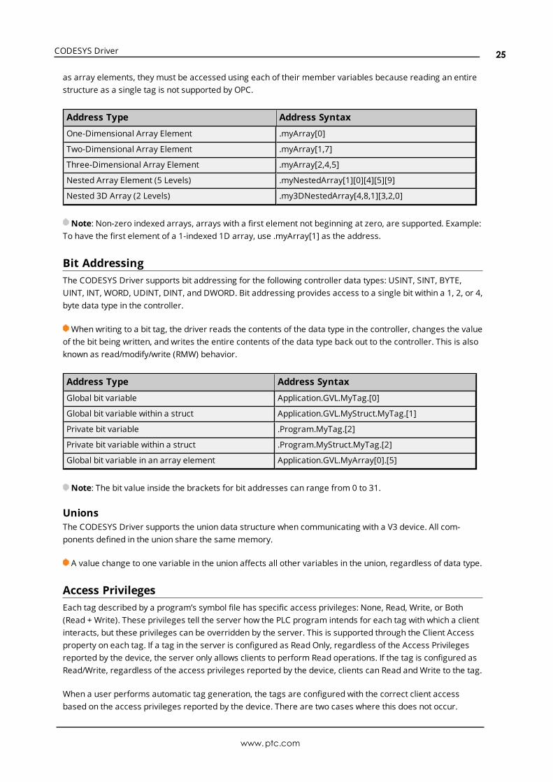
Array ElementsIf reading an entire array is not necessary or supported, it is possible to directly access a particular array ele-ment. Element access is available for one, two, and three-dimensional arrays as well as nested arrays. Seethe table below for example address syntax. It is important to note that while Structures must be accessed
www.ptc.com
24
CODESYS Driver
as array elements, they must be accessed using each of their member variables because reading an entirestructure as a single tag is not supported by OPC.
Address Type Address Syntax
One-Dimensional Array Element .myArray[0]
Two-Dimensional Array Element .myArray[1,7]
Three-Dimensional Array Element .myArray[2,4,5]
Nested Array Element (5 Levels) .myNestedArray[1][0][4][5][9]
Nested 3D Array (2 Levels) .my3DNestedArray[4,8,1][3,2,0]
Note: Non-zero indexed arrays, arrays with a first element not beginning at zero, are supported. Example:To have the first element of a 1-indexed 1D array, use .myArray[1] as the address.
Bit AddressingThe CODESYS Driver supports bit addressing for the following controller data types: USINT, SINT, BYTE,UINT, INT, WORD, UDINT, DINT, and DWORD. Bit addressing provides access to a single bit within a 1, 2, or 4,byte data type in the controller.
When writing to a bit tag, the driver reads the contents of the data type in the controller, changes the valueof the bit being written, and writes the entire contents of the data type back out to the controller. This is alsoknown as read/modify/write (RMW) behavior.
Address Type Address Syntax
Global bit variable Application.GVL.MyTag.[0]
Global bit variable within a struct Application.GVL.MyStruct.MyTag.[1]
Private bit variable .Program.MyTag.[2]
Private bit variable within a struct .Program.MyStruct.MyTag.[2]
Global bit variable in an array element Application.GVL.MyArray[0].[5]
Note: The bit value inside the brackets for bit addresses can range from 0 to 31.
UnionsThe CODESYS Driver supports the union data structure when communicating with a V3 device. All com-ponents defined in the union share the same memory.
A value change to one variable in the union affects all other variables in the union, regardless of data type.
Access PrivilegesEach tag described by a program’s symbol file has specific access privileges: None, Read, Write, or Both(Read + Write). These privileges tell the server how the PLC program intends for each tag with which a clientinteracts, but these privileges can be overridden by the server. This is supported through the Client Accessproperty on each tag. If a tag in the server is configured as Read Only, regardless of the Access Privilegesreported by the device, the server only allows clients to perform Read operations. If the tag is configured asRead/Write, regardless of the access privileges reported by the device, clients can Read andWrite to the tag.
When a user performs automatic tag generation, the tags are configured with the correct client accessbased on the access privileges reported by the device. There are two cases where this does not occur.
www.ptc.com
25
CODESYS Driver
Write Only: Tags that report as being Write Only are generated as Read/Write tags with both Read andWrite permissions as there is no Write Only setting for client access.
None: Tags that report as having permissions None are not supported either through automatic tag gen-eration or throughmanual tag creation because there is no client access setting that can correctly representthis access privilege.
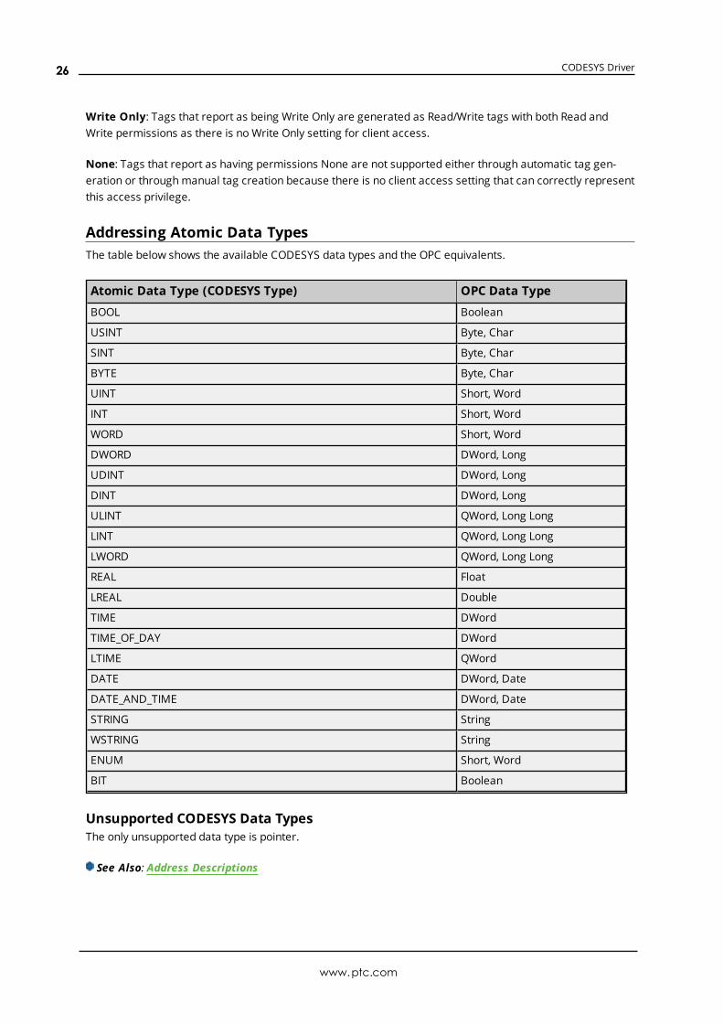
Addressing Atomic Data TypesThe table below shows the available CODESYS data types and the OPC equivalents.
Atomic Data Type (CODESYS Type) OPC Data Type
BOOL Boolean
USINT Byte, Char
SINT Byte, Char
BYTE Byte, Char
UINT Short, Word
INT Short, Word
WORD Short, Word
DWORD DWord, Long
UDINT DWord, Long
DINT DWord, Long
ULINT QWord, Long Long
LINT QWord, Long Long
LWORD QWord, Long Long
REAL Float
LREAL Double
TIME DWord
TIME_OF_DAY DWord
LTIME QWord
DATE DWord, Date
DATE_AND_TIME DWord, Date
STRING String
WSTRING String
ENUM Short, Word
BIT Boolean
Unsupported CODESYS Data TypesThe only unsupported data type is pointer.
See Also: Address Descriptions
www.ptc.com
26
CODESYS Driver
Event Log MessagesThe following information concerns messages posted to the Event Log pane in the main user interface. Con-sult the server help on filtering and sorting the Event Log detail view. Server help contains many commonmessages, so should also be searched. Generally, the type of message (informational, warning) andtroubleshooting information is provided whenever possible.
Tag generation failed because the device symbols could not be loaded. |Device = '<ChannelName.DeviceName>'.Error Type:Error
Possible Cause:The automatic tag generation operation failed because the server could not access the symbol informationon the device.
Possible Solution:
1. Verify that the device is capable of storing its own symbol information. Some devices do not have thiscapability, requiring symbol information to be manually exported and accessed by the server.
2. Ensure that the device communication parameters are correctly configured in the server.
Tag generation failed because communications could not be establishedwith the device. | Device = '<ChannelName.DeviceName>'.Error Type:Error
Possible Cause:The automatic tag generation operation failed because the server was unable to connect to the device.
Possible Solution:
1. Ensure that the device communication parameters are correctly configured in the server.
2. Check the physical connection between the server and the device.
3. If connecting to the device via a gateway, verify that the CODESYS Gateway is installed on the samehost as the server.
Tag generation failed because an unexpected failure occurred. | Device ='<ChannelName.DeviceName>'.Error Type:Error
Possible Cause:
www.ptc.com
27
CODESYS Driver
The automatic tag generation operation failed due to an unknown reason.
Possible Solution:
1. Ensure that the device communication parameters are correctly configured in the server.
2. Check the physical connection between the server and the device.
3. Ensure the device is functioning properly.
4. Contact technical support.
Internal Error. An unexpected error occurred. Resetting the PLC con-nection. | Transaction info = '<Transaction Type and Details>'.Error Type:Error
Possible Cause:An unknown error occurred.
Possible Solution:Attempt the operation again or contact technical support.
Device discovery failed because an unexpected failure occurred.Error Type:Error
Possible Cause:The device discovery operation failed due to an unknown reason.
Possible Solution:
1. Check the physical connection between the server, gateway if one is being used, and the devices.
2. Ensure the devices, and gateway if one is being used, are functioning properly.
3. Contact technical support.
Error occurred while attempting to write tag. Unable to connect to thedevice. | Tag address = '<.mystruct.innerstruct.tag>'.Error Type:Error
Possible Cause:The server failed to connect to the device.
Possible Solution:
www.ptc.com
28
CODESYS Driver
1. Ensure that the device communication parameters are correctly configured in the server.
2. Check the physical connection between the server and the device.
3. If connecting to the device via a gateway, verify that the CODESYS Gateway is installed on the samehost as the server.
Failed to browse tags.Error Type:Error
Error occurred while attempting to connect to device. Failed to retrievesymbol list from device or file.Error Type:Error
Possible Cause:
1. The server could not access the symbol information on the device.
2. The symbols do not match between the device and the specified symbol file in the device com-munication parameters.
Possible Solution:
1. Verify that the device is capable of storing its own symbol information. Some devices do not have thiscapability, and a symbol file must be specified in the device communication parameters.
2. Ensure that the device communication parameters are correctly configured in the server.
Internal error occurred while attempting to read tag. | Tag address ='<.mystruct.innerstruct.tag>'.Error Type:Error
Possible Cause:The read failed due to an unknown reason.
Possible Solution:Contact technical support.
Internal error occurred while attempting to write tag. | Tag address ='<.mystruct.innerstruct.tag>'.Error Type:Error
Possible Cause:
www.ptc.com
29
CODESYS Driver
1. Non-ASCII characters were written to the string tag.
2. The write failed due to an unknown reason.
Possible Solution:
1. Only write ASCII characters to the string tag.
2. Contact technical support.
Error occurred while attempting to read tag. Unsupported data type orinvalid address specified. | Tag address = '<.mystruct.innerstruct.tag>',data type = '<type>'.Error Type:Error
Possible Cause:
1. The specified data type is not supported.
2. The specified address is not valid.
Possible Solution:Ensure that the correct data type and address are specified.
Error occurred while attempting to read tag. The specified tag addresswas not found on the device. | Tag address = '<.my-struct.innerstruct.tag>'.Error Type:Error
Possible Cause:The tag address was not found on the device.
Possible Solution:
1. Verify that the correct address is specified.
2. Verify that the address exists on the device.
Error occurred while attempting to write tag. The specified tag addresswas not found on the device. | Tag address = '<.my-struct.innerstruct.tag>'.Error Type:Error
Possible Cause:
www.ptc.com
30
CODESYS Driver
The tag address was not found on the device.
Possible Solution:
1. Verify that the correct address is specified.
2. Verify that the address exists on the device.
Error occurred while attempting to read tag. The specified server datatype is not compatible with the device data type. | Tag address = '<.my-struct.innerstruct.tag>', server data type = '<type>', device data type ='<type>'.Error Type:Error
Possible Cause:The specified server data type is not compatible with the device data type.
Possible Solution:Change the server data type to one that is compatible with the device data type for this address.
Error occurred while attempting to write tag. The specified server datatype is not compatible with the device data type. | Tag address = '<.my-struct.innerstruct.tag>', server data type = '<type>', device data type ='<type>'.Error Type:Error
Possible Cause:The specified server data type is not compatible with the device data type.
Possible Solution:Change the server data type to one that is compatible with the device data type for this address.
Internal error occurred while attempting to connect to device. The con-figuration provided is not valid.Error Type:Error
Possible Cause:The configuration provided is not valid.
Possible Solution:Contact technical support.
www.ptc.com
31
CODESYS Driver
The browse path contains invalid characters.Error Type:Error
Possible Cause:The path specified by the user contained non-ascii characters.
Possible Solution:Remove all invalid characters.
Error occurred while attempting to read tag. The array size must matchbetween the server and device. | Tag address = '<.my-struct.innerstruct.tag>', server array size = '<length>', device array size ='<length>'.Error Type:Error
Possible Cause:The array size does not match between the server and device.
Possible Solution:Specify the same array size for both the server and device.
Error occurred while attempting to write tag. The array size must matchbetween the server and device. | Tag address = '<.my-struct.innerstruct.tag>', server array size = '<length>', device array size ='<length>'.Error Type:Error
Possible Cause:The array size does not match between the server and device.
Possible Solution:Specify the same array size for both the server and device.
Tag browsing failed because communications could not be establishedwith the device.Error Type:Error
Possible Cause:The tag browse operation failed because the server was unable to connect to the device.
Possible Solution:
www.ptc.com
32
CODESYS Driver
1. Ensure that the device communication parameters are correctly configured in the server.
2. Check the physical connection between the server and the device.
3. If connecting to the device via a gateway, verify that the CODESYS Gateway is installed on the samehost as the server.
Error occurred while attempting to read tag. The specified tag address hasa string length that is larger than the maximum supported by the server.| Tag address = '<.mystruct.innerstruct.tag>', Max length = '<number>'characters.Error Type:Error
Possible Cause:The corresponding tag on the device has a string length larger than the maximum supported by the server.
Possible Solution:Shorten the string length of the tag on the device to a value that is supported by the server.
Error occurred while attempting to write tag. The specified tag addresshas a string length that is larger than the maximum supported by theserver. | Tag address = '<.mystruct.innerstruct.tag>', Max length = '<num-ber>' characters.Error Type:Error
Possible Cause:The corresponding tag on the device has a string length larger than the maximum supported by the server.
Possible Solution:Shorten the string length of the tag on the device to a value that is supported by the server.
The browse path does not exist.Error Type:Error
Possible Cause:The user supplied an invalid path.
Possible Solution:
1. Verify the path is valid for the target device.
2. Verify the device is properly programmed.
www.ptc.com
33
CODESYS Driver
Tag browse request aborted due to unknown error.Error Type:Error
Possible Cause:
1. The runtime is shutting down.
2. An unknown error was encountered.
Possible Solution:
1. Retry the tag browse operation.
2. Contact Tech Support if the issue persists.
The browse request was canceled because the driver has been stopped.Error Type:Error
Possible Cause:The license or evaluation period for this driver has expired.
Possible Solution:Verify the driver is properly licensed.
Data type for the given address is not supported. A tag is not generatedfor this data point. | Tag address = '<.mystruct.innerstruct.tag>'.Error Type:Warning
Possible Cause:This is caused by having an unsupported data type in the PLC program.
Possible Solution:Verify that the tag is the correct data type in the programming software. Correct or use a different data type(supported by the server) or data the unsupported type contains is not accessible.
The tag could not be added to the server because the address exceeds themaximum length. | Tag address = '<.mystruct.innerstruct.tag>', Maxlength = '<1024>' characters.Error Type:Warning
Possible Cause:This is caused by having a tag address in the PLC program that exceeds the maximum length supported bythe server.
www.ptc.com
34

CODESYS Driver
Possible Solution:Restructure the PLC program so that the tag address is shorter than the maximum length.
The tag could not be added to the server because it failed address val-idation. | Tag address = '<.mystruct.innerstruct.tag>'.Error Type:Warning
Possible Cause:The tag address is malformed or is not supported by the server.
Possible Solution:
1. Verify the integrity of the symbol file or make a correction before trying again.
2. Verify or correct the tag address before trying again.
The value read from the string tag was truncated. | Tag address = '<.my-struct.innerstruct.tag>', maximum length = '<number>' characters.Error Type:Warning
Possible Cause:The value read from the string tag was longer than the buffer size reported by the device.
Possible Solution:Restart the server runtime.
The value written to the string tag was truncated. | Tag address = '<.my-struct.innerstruct.tag>', maximum length = '<number>' characters.Error Type:Warning
Possible Cause:The value written to the string tag was longer than the buffer on the device.
Possible Solution:
1. Write a value that has a length less than or equal to the buffer on the device.
2. Make the buffer on the device large enough to fit the value being written.
www.ptc.com
35
CODESYS Driver
Devices across channels must have unique address (IP address or host-name) and port combinations. | Address = '<number>', Port = '<number>',Overlapping device = '<device>'.Error Type:Warning
Possible Cause:The address and port combination has already been used for another device.
Possible Solution:Change the address and/or port for this device.
Failed to open the symbol file. | File = '<path to file>'.Error Type:Warning
The file path cannot be empty.Error Type:Warning
The symbol file was invalid or corrupt. | File = '<path to file>'.Error Type:Warning
Error opening file for tag database import. | OS Error = '<OS Supplied Mes-sage>'.Error Type:Warning
Error occurred while attempting to write tag. The bit value exceeds thesize of the controller data type. | Tag address = '<.my-struct.innerstruct.tag>', bit value = '<bit location>', controller data typesize (bytes) = '<size in bytes>'.Error Type:Warning
Error occurred while attempting to read tag. The bit value exceeds thesize of the controller data type. | Tag address = '<.my-struct.innerstruct.tag>', bit value = '<bit location>', controller data typesize (bytes) = '<size in bytes>'.Error Type:Warning
www.ptc.com
36
CODESYS Driver
Invalid address. Please enter a valid Logical Address or PLC Name.Error Type:Warning
Devices across channels must have unique Logical Address/PLC Names. |Address = '<address>', Overlapping device = '<device>'.Error Type:Warning
Some of the imported tags replaced tags of the same name in your pro-ject.Error Type:Warning
Failed to open the symbol file. | File = '<path to file>', Reason = '<errormessage from operating system>'.Error Type:Warning
The tag could not be included in the browse because the address exceedsthe maximum length. | Tag address = '<.mystruct.innerstruct.tag>', Maxlength = '<1024>' characters.Error Type:Warning
Possible Cause:This is caused by having a tag address in the PLC program that exceeds the maximum length supported bythe server.
Possible Solution:Restructure the PLC program so that the tag address is shorter than the maximum length.
The tag could not be included in the browse because it failed address val-idation. | Tag address = '<.mystruct.innerstruct.tag>'.Error Type:Warning
Possible Cause:The tag address is malformed or is not supported by the server.
Possible Solution:
1. Verify the integrity of the symbol file or make a correction before trying again.
2. Verify or correct the tag address before trying again.
www.ptc.com
37
CODESYS Driver
Failure browsing tags. | Reason = '<string indicating why the tag browsefailed>'.Error Type:Warning
Possible Cause:
1. The tag browse operation failed because the server was unable to connect to the device.
2. The supplied path is invalid.
3. The server could not access the symbol information on the device.
4. The symbols do not match between the device and the specified symbol file in the device com-munication parameters.
Possible Solution:
1. Ensure that the device communication parameters are correctly configured in the server.
2. Check the physical connection between the server and the device.
3. If connecting to the device via a gateway, verify that the CODESYS Gateway is installed on the samehost as the server.
4. Verify the path is valid for the target device.
5. Verify the device is properly programmed.
6. Verify that the device is capable of storing its own symbol information. Some devices do not have thiscapability, and a symbol file must be specified in the device communication parameters.
Tags generated. | Tag count = <count>.Error Type:Informational
www.ptc.com
38
CODESYS Driver
Index
A
Access Privileges 25
Address 16
Address Rules 22
Addressing Atomic Data Types 26
Allow Sub Groups 15
Array Elements 24
Arrays 24
Auto-Demotion 12
B
BIT 26
Bit Addressing 25
BOOL 26
Boolean 22
Byte 16, 22
BYTE 26
Byteorder 16
C
Channel Assignment 11
Char 22
Client / Server 22
Client Access 25
Communication Parameters 8, 16
Create 15
D
Data Collection 11
Data type for the given address is not supported. A tag is not generated for this data point. | Tag address= '<.mystruct.innerstruct.tag>'. 34
Data Types Description 22
www.ptc.com
39
CODESYS Driver
Date 22
DATE 26
DATE_AND_TIME 26
Delete 14
Demote on Failure 13
Demotion Period 13
Device discovery failed because an unexpected failure occurred. 28
Device Discovery Settings 9
Device Properties — Tag Generation 13
Devices across channels must have unique address (IP address or hostname) and port combinations. |Address = '<number>', Port = '<number>', Overlapping device = '<device>'. 36
Devices across channels must have unique Logical Address/PLC Names. | Address = '<address>', Over-lapping device = '<device>'. 37
DINT 26
Discard Requests when Demoted 13
Do Not Scan, Demand Poll Only 12
Double 22
Driver 11
DWord 22
DWORD 26
E
ELAU-Max4 Version 17
Endian 16
ENUM 26
Error occurred while attempting to connect to device. Failed to retrieve symbol list from device or file. 29
Error occurred while attempting to read tag. The array size must match between the server and device. |Tag address = '<.mystruct.innerstruct.tag>', server array size = '<length>', device array size ='<length>'. 32
Error occurred while attempting to read tag. The bit value exceeds the size of the controller data type. |Tag address = '<.mystruct.innerstruct.tag>', bit value = '<bit location>', controller data type size(bytes) = '<size in bytes>'. 36
Error occurred while attempting to read tag. The specified server data type is not compatible with thedevice data type. | Tag address = '<.mystruct.innerstruct.tag>', server data type = '<type>', devicedata type = '<type>'. 31
Error occurred while attempting to read tag. The specified tag address has a string length that is largerthan the maximum supported by the server. | Tag address = '<.mystruct.innerstruct.tag>', Maxlength = '<number>' characters. 33
Error occurred while attempting to read tag. The specified tag address was not found on the device. |Tag address = '<.mystruct.innerstruct.tag>'. 30
www.ptc.com
40
CODESYS Driver
Error occurred while attempting to read tag. Unsupported data type or invalid address specified. | Tagaddress = '<.mystruct.innerstruct.tag>', data type = '<type>'. 30
Error occurred while attempting to write tag. The array size must match between the server and device.| Tag address = '<.mystruct.innerstruct.tag>', server array size = '<length>', device array size ='<length>'. 32
Error occurred while attempting to write tag. The bit value exceeds the size of the controller data type. |Tag address = '<.mystruct.innerstruct.tag>', bit value = '<bit location>', controller data type size(bytes) = '<size in bytes>'. 36
Error occurred while attempting to write tag. The specified server data type is not compatible with thedevice data type. | Tag address = '<.mystruct.innerstruct.tag>', server data type = '<type>', devicedata type = '<type>'. 31
Error occurred while attempting to write tag. The specified tag address has a string length that is largerthan the maximum supported by the server. | Tag address = '<.mystruct.innerstruct.tag>', Maxlength = '<number>' characters. 33
Error occurred while attempting to write tag. The specified tag address was not found on the device. |Tag address = '<.mystruct.innerstruct.tag>'. 30
Error occurred while attempting to write tag. Unable to connect to the device. | Tag address = '<.my-struct.innerstruct.tag>'. 28
Error opening file for tag database import. | OS Error = '<OS Supplied Message>'. 36
Event Log Messages 27
F
Failed to browse tags. 29
Failed to open the symbol file. | File = '<path to file>', Reason = '<error message from operating sys-tem>'. 37
Failed to open the symbol file. | File = '<path to file>'. 36
Failure browsing tags. | Reason = '<string indicating why the tag browse failed>'. 38
Float 22
G
Gateway 17
General 10
Generate 14
Global 23
Global bit 25
Global Tags 22
www.ptc.com
41
CODESYS Driver
H
Help Contents 5
Hostname 16
I
ID 11
Identification 10
Initial Updates from Cache 12
INT 26
Internal error occurred while attempting to connect to device. The configuration provided is not valid. 31
Internal error occurred while attempting to read tag. | Tag address = '<.mystruct.innerstruct.tag>'. 29
Internal error occurred while attempting to write tag. | Tag address = '<.mystruct.innerstruct.tag>'. 29
Internal Error. An unexpected error occurred. Resetting the PLC connection. | Transaction info = '<Trans-action Type and Details>'. 28
Invalid address. Please enter a valid Logical Address or PLC Name. 37
K
Keep Alive 9
L
Layer 7 16-17
LINT 26
Long 22
Long Long 22
LREAL 26
LTIME 26
LWORD 26
M
Method 18
Model 11
Motorola 16-17
www.ptc.com
42
CODESYS Driver
N
Name 10
Nested Structures 24
None 25
O
On Device Startup 14
On Duplicate Tag 14
On Property Change 14
Operating Mode 11
Order 16
Overview 5
Overwrite 14
OWord 22
P
Parent Group 15
Password 18
Performance Optimization 21
PLC 17
Port 16
Private 23-24
Private bit 25
Program Tags 23
Protocol 5, 17
R
Read, Write 25
Read/Write 25
REAL 26
Redundancy 20
Request Timeout 17
Respect Tag-Specified Scan Rate 12
www.ptc.com
43
CODESYS Driver
S
ScanMode 12
Setup 5
Short 22
Signed 22
Simulated 11
SINT 26
Some of the imported tags replaced tags of the same name in your project. 37
String 22
STRING 26
Symbol 17
Symbolic 22
T
Tag Addressing 23
Tag browse request aborted due to unknown error. 34
Tag browsing failed because communications could not be established with the device. 32
Tag Generation 13
Tag generation failed because an unexpected failure occurred. | Device = '<Chan-nelName.DeviceName>'. 27
Tag generation failed because communications could not be established with the device. | Device ='<ChannelName.DeviceName>'. 27
Tag generation failed because the device symbols could not be loaded. | Device = '<Chan-nelName.DeviceName>'. 27
Tag Import Settings 18
Tag Scope 22
Tags generated. | Tag count = <count>. 38
Tags per Request 18
Target 17
The browse path contains invalid characters. 32
The browse path does not exist. 33
The browse request was canceled because the driver has been stopped. 34
The file path cannot be empty. 36
The symbol file was invalid or corrupt. | File = '<path to file>'. 36
The tag could not be added to the server because it failed address validation. | Tag address = '<.my-struct.innerstruct.tag>'. 35
The tag could not be added to the server because the address exceeds the maximum length. | Tagaddress = '<.mystruct.innerstruct.tag>', Max length = '<1024>' characters. 34
www.ptc.com
44
CODESYS Driver
The tag could not be included in the browse because it failed address validation. | Tag address = '<.my-struct.innerstruct.tag>'. 37
The tag could not be included in the browse because the address exceeds the maximum length. | Tagaddress = '<.mystruct.innerstruct.tag>', Max length = '<1024>' characters. 37
The value read from the string tag was truncated. | Tag address = '<.mystruct.innerstruct.tag>', max-imum length = '<number>' characters. 35
The value written to the string tag was truncated. | Tag address = '<.mystruct.innerstruct.tag>', max-imum length = '<number>' characters. 35
TIME 26
TIME_OF_DAY 26
Timeouts to Demote 13
U
UDINT 26
UINT 26
ULINT 26
Unsigned 22
Unsupported 22, 26
User Credentials 18
Username 18
USINT 26
V
V2.3 18
V3 18
W
Word 22
WORD 26
WSTRING 26
www.ptc.com
45