Embed Size (px)
Citation preview
The coming year promises to be an ex-citing one for the Foundation. In 2005, the Foundation plans to roll out the Tenth Edition of the Manual of Cross-Connection Control to coincide with the Foundation’s 60th An-niversary. In order to prepare for the com-ing year the Founda-tion will undergo some changes from a marketing standpoint.
First of all, as you can tell, Cross Talk has un-Cross Talk has un-Cross Talkdergone a transforma-tion. The newsletter will continue to focus on issues concern-ing cross-connection control and backfl ow. The new look for Cross Talk is designed to help the reader Cross Talk is designed to help the reader Cross Talklocate stories of interest quickly and effi ciently. Cross Talk’s new appearance will correspond with other marketing tools that will undergo a face-lift.
Furthermore, new to this issue is the USC Viterbi School of Engineering sig-
Contents Flipping the Disc p. 3
Thermal Expansion p. 4
10th Edition Manual p. 7
A New Look nature that can be found on the bottom right of the front page. The school of engineer-ing has gone through a face-lift of its own. As one of the nation’s fi nest engineering schools, a strong and coherent visual identity is essential. The Foundation is proud to be a part of the Viterbi School of Engineering.
Foundation members will notice the Viterbi signature and its ‘V’ mark on all of its training tools and marketing tools by the end of the year.
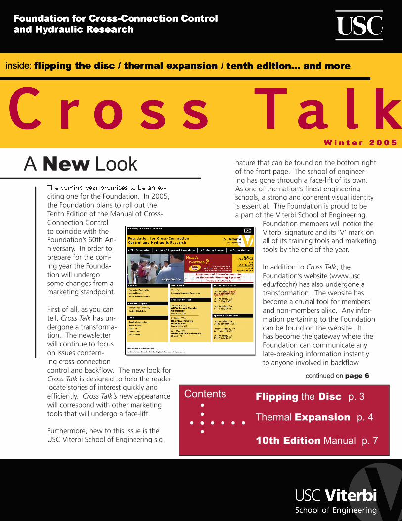
In addition to Cross Talk, the Foundation’s website (www.usc.edu/fccchr) has also undergone a transformation. The website has become a crucial tool for members and non-members alike. Any infor-mation pertaining to the Foundation can be found on the website. It has become the gateway where the Foundation can communicate any late-breaking information instantly to anyone involved in backfl ow
continued on page 6
FoundationFoundationMembershipMembership
The Foundation’s Membership Program provides many benefi ts to the Members of the Foundation. These include: a twenty-fi ve percent discount on manuals, twenty percent dis-count on Foundation Training Courses for any employee of the Member company/organi-zation, the List of Approved Backfl ow Prevention Assemblies, printed quarterly, and access to the up-to-the-minute version of the List for those Members with Internet access.
Members are encouraged to call the Foundation with technical questions. The Founda-tion’s Engineering Staff is available to assist Members with the various aspects of fi eld testing backfl ow preventers, installing backfl ow preventers and administering their cross-connection control program.
Many consider their Membership with the Foundation one of their best forms of insurance to protect the agency from liability involved when a distribution system becomes contami-nated or polluted through cross-connections. Membership in the Foundation helps to provide the tools needed to effectively initiate and run a cross-connection control program.
Below is a list of those who have become members of the Foundation this past quarter:
Advance Custom Sensor, Inc.
Brown’s Heating & Air Cond.
Compton, City of
Contra Coasts Water District
Defense Depot San Joaquin
Dekalb County
Doug Ayers
Fluid Resources Management
Frank M. Sterzinar, Jr.
Hunt’s Water Services
Interlakes Mechanical
Liege Corporation
Cross TalkCross Talk WINTER 2005 Page 2 Page 2
Lockheed Martin Aeronautics
Mark Rippon
Orange County Sanitation District
Pittsburg, City of
Public Works Center Detachment
R.J. Briner Plumbing
Surrey, City of- Engineering Department
Turlock, City of
Valley Center Municipal Water District
Virginia Beach, City of
Water Specialist Consultants
WTS Association
Cross Talk is published by the Foundation for Cross-Connection Control and Hydraulic Research at the University of Southern California for Foundation Members. Limited additional copies
are available to Members upon request.2005 © University of Southern California.
All rights reserved.
Cross Talk WINTER 2005 Page 3 Page 3
A common question received by the Founda-tion Engineering Staff is: “When repairing a backfl ow preventer is it OK to fl ip the disc?”
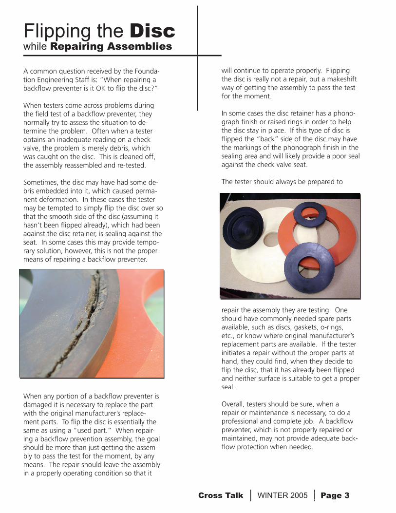
When testers come across problems during the fi eld test of a backfl ow preventer, they normally try to assess the situation to de-termine the problem. Often when a tester obtains an inadequate reading on a check valve, the problem is merely debris, which was caught on the disc. This is cleaned off, the assembly reassembled and re-tested.
Sometimes, the disc may have had some de-bris embedded into it, which caused perma-nent deformation. In these cases the tester may be tempted to simply fl ip the disc over so that the smooth side of the disc (assuming it hasn’t been fl ipped already), which had been against the disc retainer, is sealing against the seat. In some cases this may provide tempo-rary solution, however, this is not the proper means of repairing a backfl ow preventer.
When any portion of a backfl ow preventer is damaged it is necessary to replace the part with the original manufacturer’s replace-ment parts. To fl ip the disc is essentially the same as using a “used part.” When repair-ing a backfl ow prevention assembly, the goal should be more than just getting the assem-bly to pass the test for the moment, by any means. The repair should leave the assembly in a properly operating condition so that it
Flipping the Discwhile Repairing Assemblies
will continue to operate properly. Flipping the disc is really not a repair, but a makeshift way of getting the assembly to pass the test for the moment.
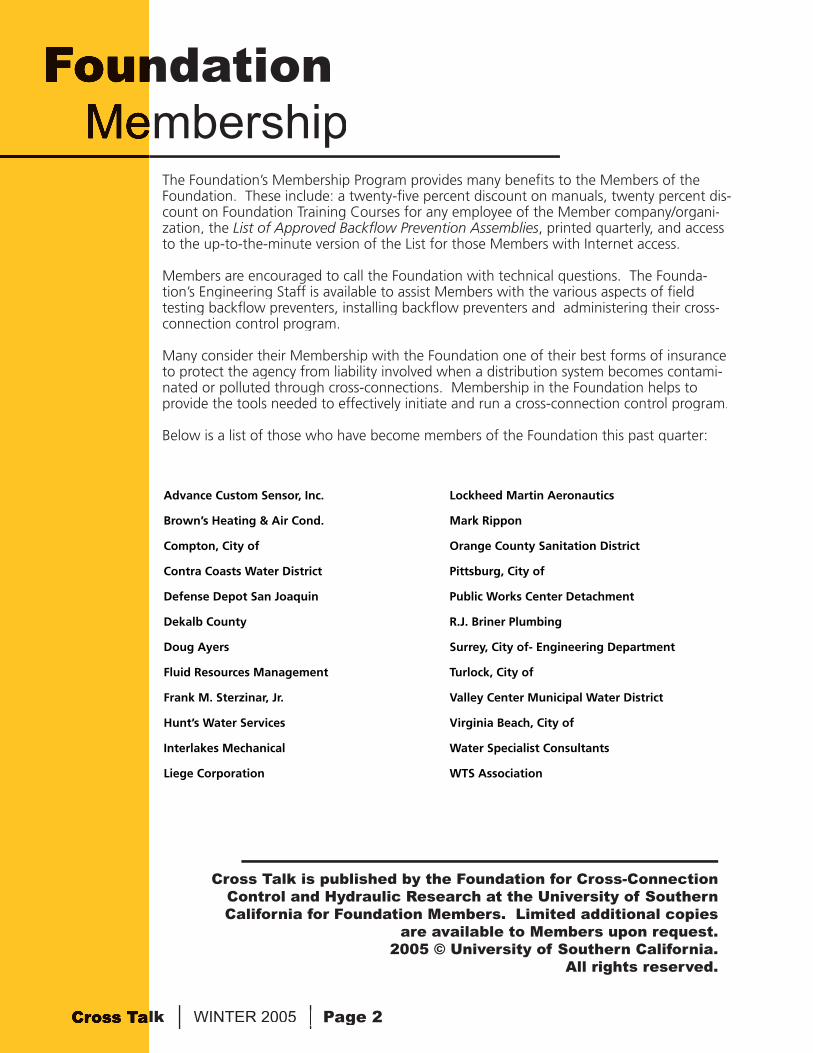
In some cases the disc retainer has a phono-graph fi nish or raised rings in order to help the disc stay in place. If this type of disc is fl ipped the “back” side of the disc may have the markings of the phonograph fi nish in the sealing area and will likely provide a poor seal against the check valve seat.
The tester should always be prepared to
repair the assembly they are testing. One should have commonly needed spare parts available, such as discs, gaskets, o-rings, etc., or know where original manufacturer’s replacement parts are available. If the tester initiates a repair without the proper parts at hand, they could fi nd, when they decide to fl ip the disc, that it has already been fl ipped and neither surface is suitable to get a proper seal.
Overall, testers should be sure, when a repair or maintenance is necessary, to do a professional and complete job. A backfl ow preventer, which is not properly repaired or maintained, may not provide adequate back-fl ow protection when needed.
Cross Talk WINTER 2005 Page 4 Page 4
One of the consequences of installing a backfl ow prevention assembly on any wa-ter system is the system becoming a closed system. A closed system is a system, which is not open to the atmosphere. A pressurized tank would be a closed system, since there is no means for the pressure to escape.
A water user’s system may be considered an open system if there is no backfl ow protec-tion. Water fl ows from the water supplier into the water user’s premises through the water meter. Should something cause the pressure on the water user’s property to increase, water can freely fl ow back out into the water distribution system.
What can cause the water user’s system to increase in pressure?
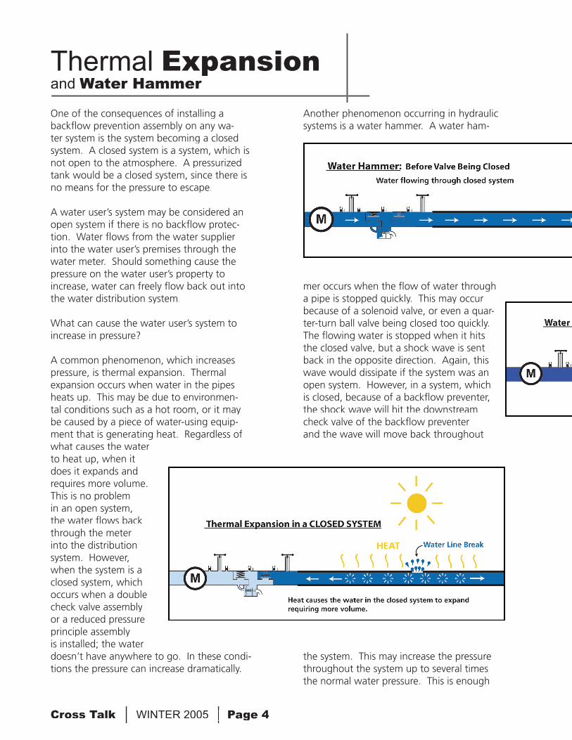
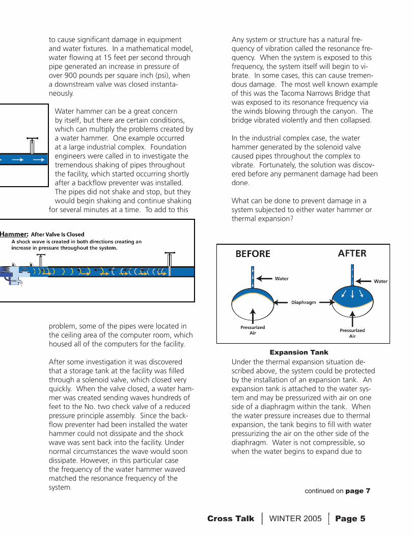
A common phenomenon, which increases pressure, is thermal expansion. Thermal expansion occurs when water in the pipes heats up. This may be due to environmen-tal conditions such as a hot room, or it may be caused by a piece of water-using equip-ment that is generating heat. Regardless of what causes the water to heat up, when it does it expands and requires more volume. This is no problem in an open system, the water fl ows back through the meter into the distribution system. However, when the system is a closed system, which occurs when a double check valve assembly or a reduced pressure principle assembly is installed; the water doesn’t have anywhere to go. In these condi-tions the pressure can increase dramatically.
Thermal Expansionand Water Hammer
Another phenomenon occurring in hydraulic systems is a water hammer. A water ham-
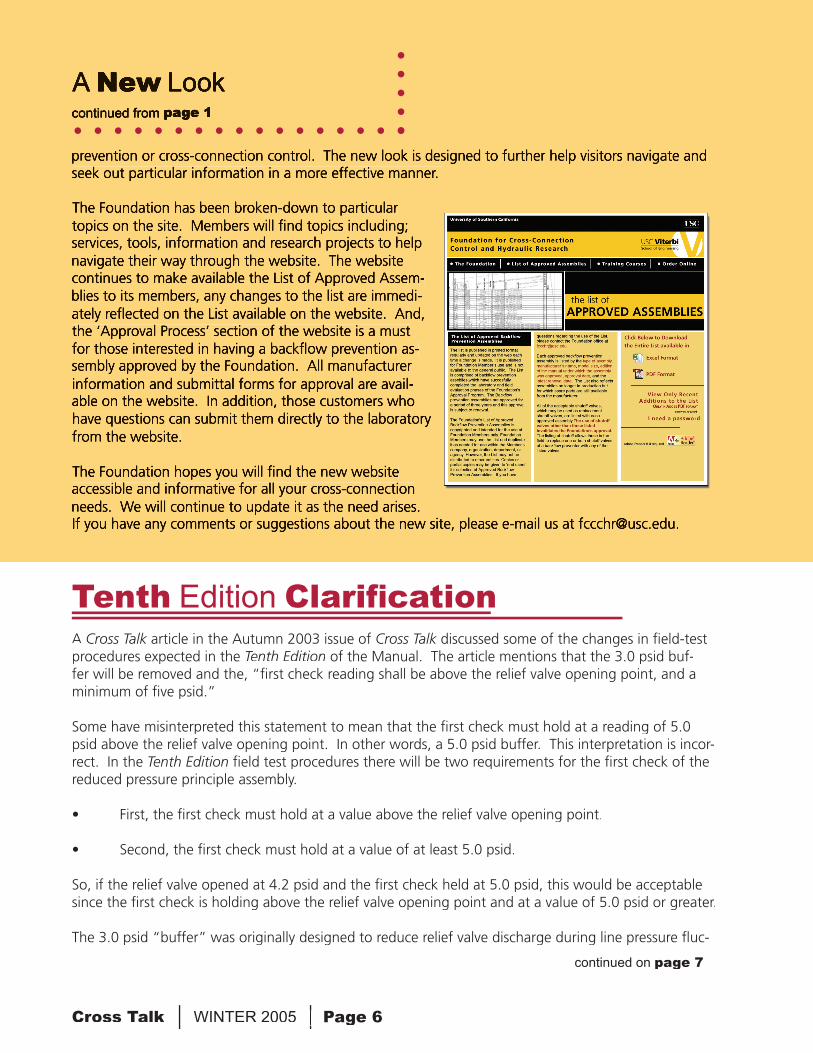
mer occurs when the fl ow of water through a pipe is stopped quickly. This may occur because of a solenoid valve, or even a quar-ter-turn ball valve being closed too quickly. The fl owing water is stopped when it hits the closed valve, but a shock wave is sent back in the opposite direction. Again, this wave would dissipate if the system was an open system. However, in a system, which is closed, because of a backfl ow preventer, the shock wave will hit the downstream check valve of the backfl ow preventer and the wave will move back throughout
the system. This may increase the pressure throughout the system up to several times the normal water pressure. This is enough
Cross Talk WINTER 2005 Page 5 Page 5
to cause signifi cant damage in equipment and water fi xtures. In a mathematical model, water fl owing at 15 feet per second through pipe generated an increase in pressure of over 900 pounds per square inch (psi), when a downstream valve was closed instanta-neously.
Water hammer can be a great concern by itself, but there are certain conditions, which can multiply the problems created by a water hammer. One example occurred at a large industrial complex. Foundation engineers were called in to investigate the tremendous shaking of pipes throughout the facility, which started occurring shortly after a backfl ow preventer was installed. The pipes did not shake and stop, but they would begin shaking and continue shaking
for several minutes at a time. To add to this
problem, some of the pipes were located in the ceiling area of the computer room, which housed all of the computers for the facility.
After some investigation it was discovered that a storage tank at the facility was fi lled through a solenoid valve, which closed very quickly. When the valve closed, a water ham-mer was created sending waves hundreds of feet to the No. two check valve of a reduced pressure principle assembly. Since the back-fl ow preventer had been installed the water hammer could not dissipate and the shock wave was sent back into the facility. Under normal circumstances the wave would soon dissipate. However, in this particular case the frequency of the water hammer waved matched the resonance frequency of the system.
Any system or structure has a natural fre-quency of vibration called the resonance fre-quency. When the system is exposed to this frequency, the system itself will begin to vi-brate. In some cases, this can cause tremen-dous damage. The most well known example of this was the Tacoma Narrows Bridge that was exposed to its resonance frequency via the winds blowing through the canyon. The bridge vibrated violently and then collapsed.
In the industrial complex case, the water hammer generated by the solenoid valve caused pipes throughout the complex to vibrate. Fortunately, the solution was discov-ered before any permanent damage had been done.
What can be done to prevent damage in a system subjected to either water hammer or thermal expansion?
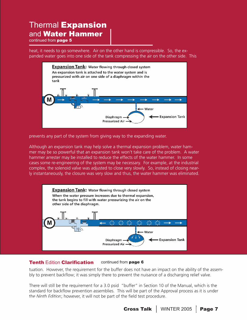
Under the thermal expansion situation de-scribed above, the system could be protected by the installation of an expansion tank. An expansion tank is attached to the water sys-tem and may be pressurized with air on one side of a diaphragm within the tank. When the water pressure increases due to thermal expansion, the tank begins to fi ll with water pressurizing the air on the other side of the diaphragm. Water is not compressible, so when the water begins to expand due to
Expansion Tank
continued on page 7
Cross Talk WINTER 2005 Page 6 Page 6
prevention or cross-connection control. The new look is designed to further help visitors navigate and seek out particular information in a more effective manner.
The Foundation has been broken-down to particular topics on the site. Members will fi nd topics including; services, tools, information and research projects to help navigate their way through the website. The website continues to make available the List of Approved Assem-blies to its members, any changes to the list are immedi-ately refl ected on the List available on the website. And, the ‘Approval Process’ section of the website is a must for those interested in having a backfl ow prevention as-sembly approved by the Foundation. All manufacturer information and submittal forms for approval are avail-able on the website. In addition, those customers who have questions can submit them directly to the laboratory from the website.
The Foundation hopes you will fi nd the new website accessible and informative for all your cross-connection needs. We will continue to update it as the need arises. If you have any comments or suggestions about the new site, please e-mail us at [email protected].
A New Lookcontinued from page 1
A Cross Talk article in the Autumn 2003 issue of Cross Talk article in the Autumn 2003 issue of Cross Talk Cross Talk discussed some of the changes in fi eld-test procedures expected in the Tenth Edition of the Manual. The article mentions that the 3.0 psid buf-fer will be removed and the, “fi rst check reading shall be above the relief valve opening point, and a minimum of fi ve psid.”
Some have misinterpreted this statement to mean that the fi rst check must hold at a reading of 5.0 psid above the relief valve opening point. In other words, a 5.0 psid buffer. This interpretation is incor-rect. In the Tenth Edition fi eld test procedures there will be two requirements for the fi rst check of the reduced pressure principle assembly.
• First, the fi rst check must hold at a value above the relief valve opening point.
• Second, the fi rst check must hold at a value of at least 5.0 psid.
So, if the relief valve opened at 4.2 psid and the fi rst check held at 5.0 psid, this would be acceptable since the fi rst check is holding above the relief valve opening point and at a value of 5.0 psid or greater.
The 3.0 psid “buffer” was originally designed to reduce relief valve discharge during line pressure fl uc-
Tenth Edition Clarifi cation
continued on page 7
Cross Talk WINTER 2005 Page 7 Page 7
Thermal Expansionand Water Hammercontinued from page 5
heat, it needs to go somewhere. Air on the other hand is compressible. So, the ex-panded water goes into one side of the tank compressing the air on the other side. This
prevents any part of the system from giving way to the expanding water.
Although an expansion tank may help solve a thermal expansion problem, water ham-mer may be so powerful that an expansion tank won’t take care of the problem. A water hammer arrester may be installed to reduce the effects of the water hammer. In some cases some re-engineering of the system may be necessary. For example, at the industrial complex, the solenoid valve was adjusted to close very slowly. So, instead of closing near-ly instantaneously, the closure was very slow and thus, the water hammer was eliminated.
tuation. However, the requirement for the buffer does not have an impact on the ability of the assem-bly to prevent backfl ow; it was simply there to prevent the nuisance of a discharging relief valve.
There will still be the requirement for a 3.0 psid “buffer” in Section 10 of the Manual, which is the standard for backfl ow prevention assemblies. This will be part of the Approval process as it is under the Ninth Edition; however, it will not be part of the fi eld test procedure.
continued from page 6Tenth Edition Clarifi cation
Foundation for Cross-ConnectionControl and Hydraulic Research
University of Southern CaliforniaKaprielian Hall 200Los Angeles, California 90089-2531
First ClassUS Postage PAID
University of Southern California
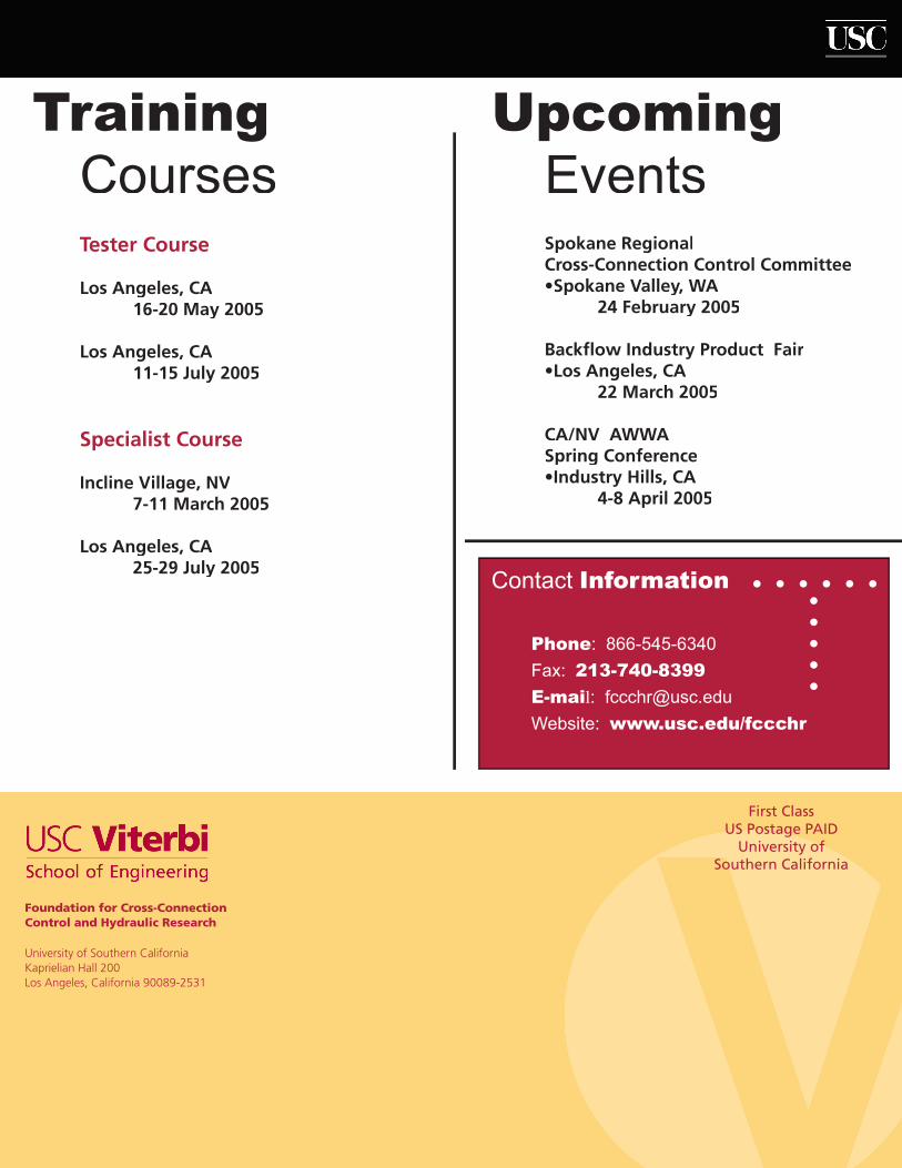
TrainingCourses
UpcomingEvents
Tester Course
Los Angeles, CA 16-20 May 2005
Los Angeles, CA 11-15 July 2005
Specialist Course
Incline Village, NV 7-11 March 2005
Los Angeles, CA 25-29 July 2005
Spokane RegionalCross-Connection Control Committee•Spokane Valley, WA 24 February 2005
Backfl ow Industry Product Fair•Los Angeles, CA 22 March 2005
CA/NV AWWASpring Conference•Industry Hills, CA 4-8 April 2005
Contact Information
Phone: 866-545-6340
Fax: 213-740-8399
E-mail: [email protected]
Website: www.usc.edu/fccchr